

Page 1
CVM-WM100 PLUS
UHF 1-Trigger-2 Wireless Microphone
User Manual
Page 2

Page 3
Foreword
Thanks for purchasing COMICA WM100 Plus wireless microphone;
WM100 Plus is a wireless microphone with dual-transmitter triggered by one
receiver, with two AA batteries. It utilizes UHF wireless FM technology and LCD
high-resolution lattice screen, 16-level adjustable volume, and is integrated into
LCF(Low cut filter) , Auto IR Channel-match, Stereo / Mono switchable audio
mode, RF signal strength adjustment, MIC/LINE IN input dual selection, Power
monitoring at receiver end, Sound pickup dynamic display, Backlight adjustment
and other functions, at the same time with strong shielding anti-noise
performance, it’s a high-quality microphone to broadcasting level;
To ensure the smooth use and safety of the product, please carefully read this
instruction before using and properly assemble and operate.
Main Features
. 1-trigger-2,Perfectly Support Two Transmitters and One Receiver Work Simultaneously
. Working Distance Up to 100m (Open Area 100m, 60m in area with obstacle)
. M/S Switch, LCF, 16-levels Adjusted Gain Control, Muting Functions
. AA Batteries and Support External Charging
. Support Real-time Monitor
. Volume Dynamic Monitor
. Adjusted RF Power
. Lattice LCD Display, High Resolution
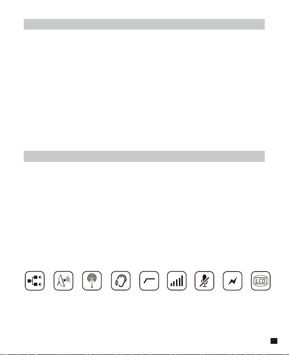
1-Trigger-2 48 Channels
100m Working
Distance
Real-time
Monitor
Low Cut Filter
16-Levels
Adjusted Gain Control
Muting Mode
Support
External Charging
Lattice LCD
1
Page 4
Notice
Transmitter should be used more than 10cm from Receiver, when the distance is
less than 10cm, Receiver’s wireless signal receiving part will take protect action to
shut down wireless signal receiving, then audio may be intermittent, which is
normal;
When using auto IR sync, please stay within 30cm, otherwise the signal may be so
weak that the sync will not be successful;
In the case of stereo/mono mode switch, please preset the mode before using to
avoid the transient interference caused by switching during usage;
The antenna will affect the working distance. Please protect the antenna and avoid
any man-made damage;
The working distance will be affected by the surrounding environment. Please try
to keep the environment open without interference during usage, and close the
WIFI of the device itself;
When using this product in a short distance, it is recommended to set RF strength
at ‘LOW’ to reduce the power consumption;
For smartphone shooting, customers must separately purchase a TRS-TRRS
audio converting cable,and pay attention to set the mobile phone mode to 'Flight
Mode' to avoid incoming call interference(It does not support the partial original
recording of android systems, the third-party APP is recommended to be used in
this case);
Please keep this product in dry environment;
Do not expose the device in rain or humid environment, otherwise there will be a
danger of short circuit;
2
Page 5
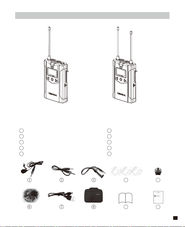
Package Contents
Main Parts:
Lavalier Transmitter (TX) Receiver (RX)
Accessories:
3.5mm Mic Audio Input Cable x 2 pcs
1
3.5mm-3.5mm Audio Output Cable x 1 pcs
2
3
3.5mm-XLR Audio Output Cable x 1 pcs
4
Belt Clip x 3pcs
5
Camera mount x 1 pcs
Wind Muff x 2pcs
6
USB power input cable x 1 pcs
7
8
Portable Bag x 1 pcs
9
User Manual x 1 pcs
10
Warranty Card x 1 pcs
1
6
2
7
3
8
4
9
5
10
3
Page 6
Components and Instruction
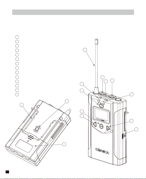
Components
Lavalier Transmitter (TX)
1
Antenna
2
Working Status Indicator
3
On-off / Muting Button
4
SET Function Menu
5
Function Selection Button -
6
LINE IN External Input
7
IR Sensor
8
Mic External Input
9
IR Status Indicator
10
Function Selection Button +
11
Micro USB Port for External Charging
12
Belt Clip
13
1/4 Thread
14
Battery Tray
12
1
6
8
2
3
13
4
5
14
7
9
10
11
4
Page 7
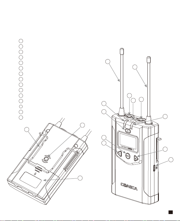
Receiver (RX)
1
Group A Antenna
2
Group B Antenna
3
Group A Working Status Indicator
4
On-Off Button
5
SET Function Button
6
Function Selection Button -
7
3.5mm Audio Input Jack
8
IR Sensor
9
3.5mm monitoring Jack
10
Group B Working Status Indicator
11
Function Selection Button +
12
Micro USB Port for External Charging
13
Belt Clip
14
1/4 Thread
15
Battery Tray
13
1
3
4
14
5
6
15
2
7
9
8
10
11
12
5
Page 8

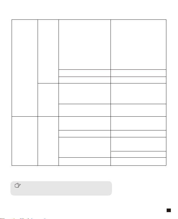
Function Button Instruction
Lavalier
Transmitter
/ Receiver
6
Long Press
Power / Muting Button
Short Press
Power On / Off
Muting Mode
the mute function can be
(
activated only when the
screen is lighted up
)
Long Press Enter the function
adjustment menu
SET Function Menu
Short Press
1.Confirm the selected
function
2.Exit the function
adjustment menu
+ Button
- Button
Short Press
Short Press
Function Adjustment (+)
Function Adjustment (-)
Low cut function:
Appropriately cut the low frequency part of the sound, reduce the noise
of the low frequency part, to make target sound more clean and clear.
Signal strength high/low switching effect:
With high signal strength, the working distance is up to 60-100m,
but high power consumption and short battery life.
With low signal strength, the working distance is up to 30-60m,
but low power consumption and long battery life.
Page 9
Indicator Light Instruction
Green Light Keeps On
Transmitter
Receiver
RF
IR
A IR/RF
B IR/RF
Red Light Keeps On
Red Light Flicker
Green Light Keeps On
Red Light Flicker
Green Light Keeps On
Green Light Flicker
Red Light Flicker
Red light keeps on
Normal Recording Status
This state is only for the
(
transmitter, when the
channel matches
successfully, the receiver
can pick up the sound
)
Muting Mode
Low-power reminder
Channel matches
No matter the channel
(
matches or not
)
Channel in the match...
only for IR Sync
(
)
Normal working status after
the channel matches
Channel doesn’t match
Channel in the match...
only for IR Sync
(
)
Low-power reminder
Group closed
A IR/RF: Group A Working Status Indicator
B IR/RF: Group B Working Status Indicator
7
Page 10
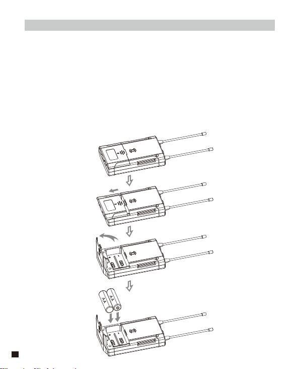
Installation and Usage
Preparation Before Usage
(Transmitter Operating Steps same with Receiver)
1. Prepare Power Supply
There're two ways of Power Supply, you can optionally choose AA
batteries or External charging:
1.1 Install two AA batteries into the battery tray according to their
positive and negative electrode.
8
Page 11
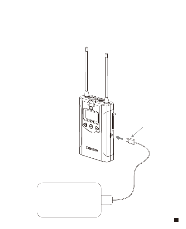
1.2 Charging with External Power
Insert micro USB cable to the USB charging port to realize
external power charging
Micro USB
POWER
9
Page 12
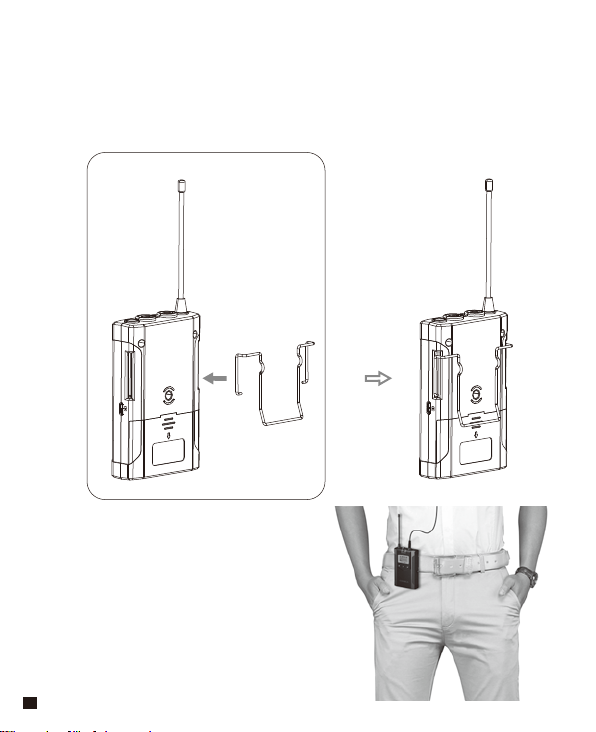
2.Belt Clip Installation
Please install the belt clip according to the illustration if you require
the way of connection.
10
Page 13
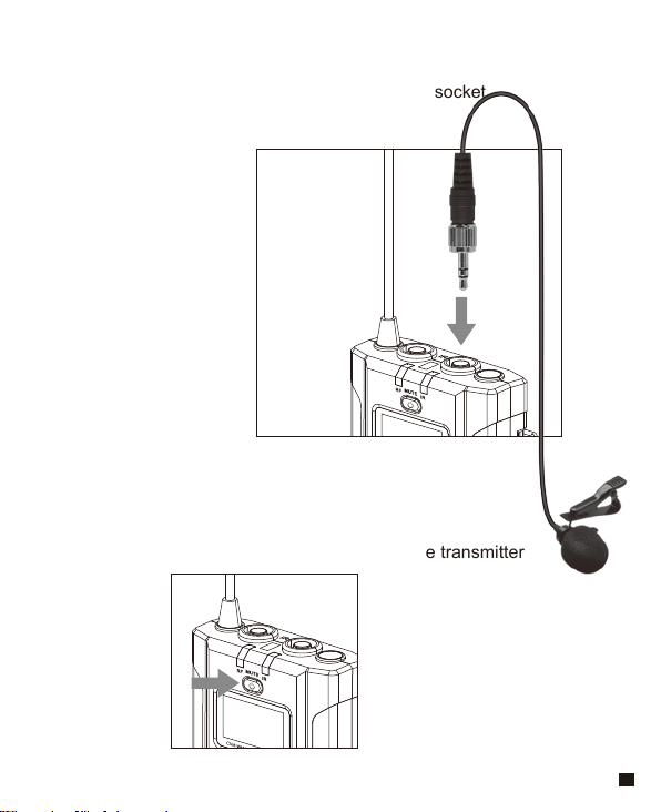
3. Lavalier Transmitter Installation
3.1 Insert the 3.5mm audio input line into MIC socket
3.2 Long press the power button to turn on the transmitter
11
Page 14
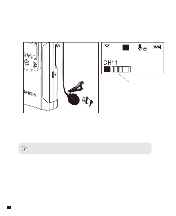
3.3 Target the MIC to the audio source and check the working status
according to the volume indicator on the screen
A
H
Group A
570.875MHz
A
Audio Dynamic Display Bar
3.4 After the channel matching with the receiver, it can be used
Please refer to screen operation instruction for channel matching.
12
Page 15
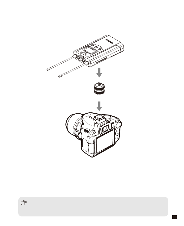
4. Receiver Installation
4.1 Connect receiver to your video equipment through the camera
mount
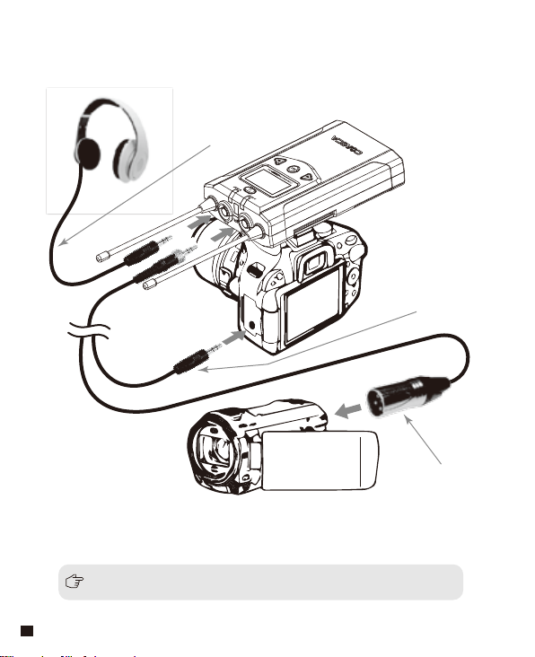
4.2 Connect one end of the 3.5mm-3.5mm audio OUTPUT cable to the
OUTPUT port of WM200RX and another end to the AUDIO INPUT
port of the camera or camcorder.Insert the headphone into the
3.5mm monitoring port for real-time monitoring and then long press
power button to turn on the receiver.
Most DSLR cameras has 3. 5MM port, if you use the XLR camcorder,
you need to use the 3. 5mm-XLR audio output cable.
13
Page 16
3.5mm Audio Output
Monitoring Cable
4.3 After the channel matching with the receiver, it can be used
Please refer to screen operation instruction for channel matching.
14
3.5mm-3.5mm
Audio Output Cable
3.5MM-XLR Audio
Output Cable
Page 17
Screen Display and Operation Instruction
Lavalier Transmitter
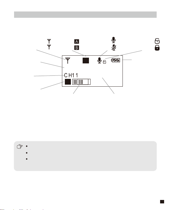
Screen Display Instruction
Signal Strength High
Signal Strength Low
H
L
Group A
Group B
Normal recording
Muting
Muting(Unlocking
Muting(Locking
)
)
Group A/B
H
A
Group A
Channel
570.875MHz
A
Group A/B
Audio dynamic display bar Channel Frequency
Mic mode is for Microphone input;
Line in mode is for external audio input, such as smartphone player;
Selecting the corresponding input mode will bring you a better audio
experience.
Power Indication
15
Page 18
Operation Instruction
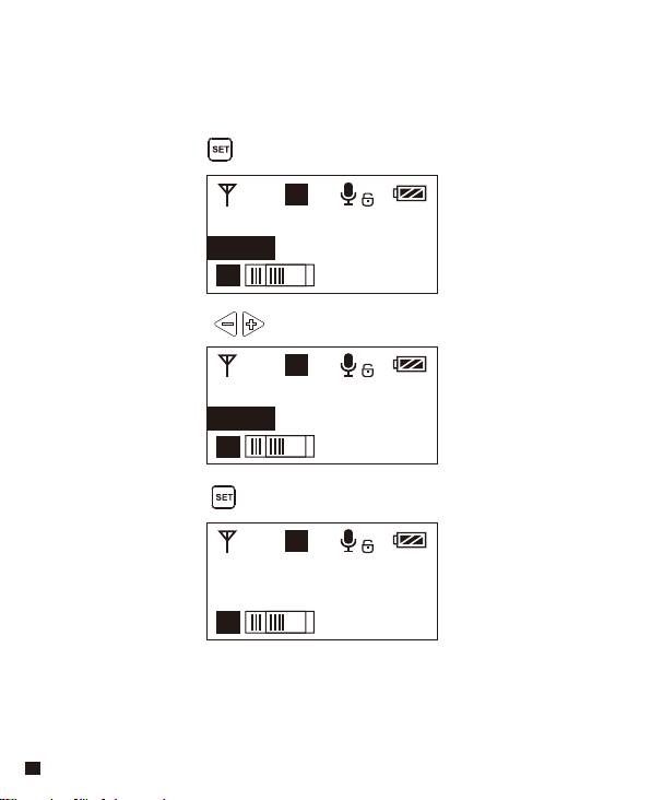
1.Manually Adjust the Channel of Transmitter
1.1 Long press button to CH setting display page
A
H
Group A
CH11 570.875MHz
A
1.2 Short press button to select the channel
A
H
Group A
CH8 570.125MHz
A
1.3 Short press button to confirm
A
H
Group A
CH8 570.125MHz
A
16
Page 19
2.Group A/B Selection
2.1 Press button to ‘ Group Setting ’ display page
A
H
Group Setting
Group A
A
2.2 Long press button to ‘ Group Setting ’ setting page
A
H
Group Setting
Group A
A
2.3 Press button to select the group
A
H
Group Setting
Group B
A
2.4 Short press button to confirm
B
H
Group Setting
Group B
B
17
Page 20
Low Cut Filter
3.
3.1 Press button to ‘ Low Cut Filter ’ display page
‘ Low/High/OFF ’ Adjustment
A
H
Low Cut Filter
OFF
A
3.2 Long press button to enter ‘ Low Cut Filter ’ setting page
A
H
Low Cut Filter
OFF
A
3.3 Press button to select LCF ‘
Low Cut Filter
Low
A
3.4 Short press button to confirm
Low-cut function will filter out the low-frequency part of the audio source,
such as the chirping and crowd noise, and the main audio source will
be more crisp. Low cut divided into low cut in low range and low cut in
high range, low range is to filter out part of the noise, while high range
of low cut filter out all noise. Turn off the low cut to restore the true, the
main source will be more vigorous, but it can be adjusted according
18
to actual needs.
H
Low/High/OFF ’
A
Page 21
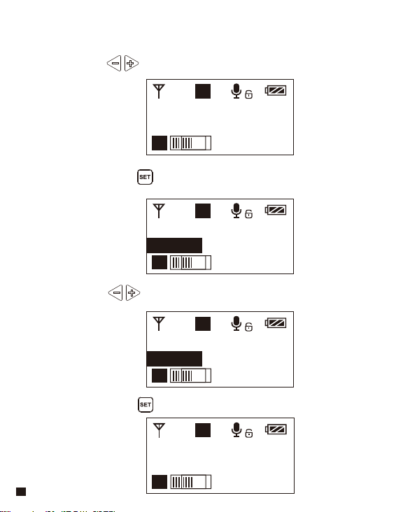
4.Transmitting Signal Strength ‘ High/Low ’ Adjustment
4.1 Press button to ‘ RF Power ’ display page
A
H
RF Power
High
A
4.2 Long press button to ‘ RF Power ’ setting page
A
H
RF Power
High
A
4.3 Press button to adjust the transmitting signal strength
A
H
RF Power
Low
A
4.4 Short press button to confirm
A
L
RF Power
Low
A
19
Page 22
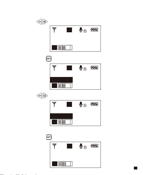
5.Muting Mode Enable/ Disable
5.1 Press button to ‘ Muting ’ display page
A
H
Muting
Enable
A
5.2 Long press button to ‘ Muting ’ setting page
A
H
Muting
Enable
A
5.3 Press button to select Muting mode Enable/ Disable
A
H
Muting
Disable
A
5.4 Short press button to confirm
A
H
Muting
Disable
20
A
Page 23

When set to ‘ Disable ’, the muting function cannot be used, the icon is:
When set to ‘ Enable ’, the muting function works, the icon is:
The muting mode can be controlled only when the screen is on, press any
button to light the screen and then press the button to switch the
muting mode.
21
Page 24

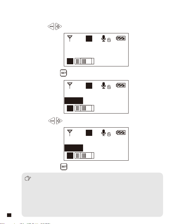
6.Backlight ‘ Lighting Time/Turn Off ’ Adjustment
6.1 Short Press button to ‘ Backlight ’ display page
A
H
Backlight
15s
A
6.2 Long press button to ‘ Backlight ’ setting page
A
H
Backlight
15s
A
6.3 Short press button to adjust the backlight lighting time
or you can turn it off for power saving
A
H
Backlight
60s
A
6.4 Short press button to confirm
A
H
Backlight
00s
22
A
Page 25

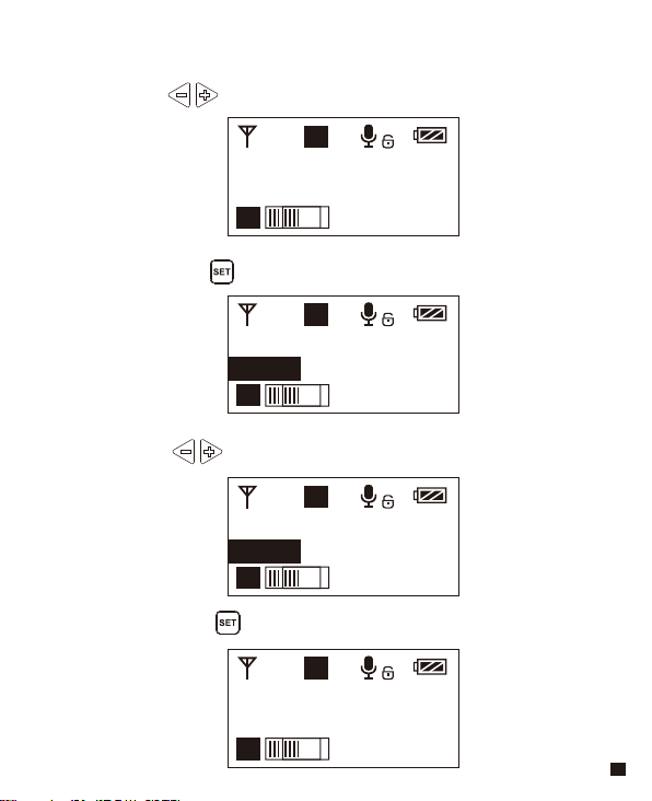
7. Reset to Defaults
7.1 Press button to ‘ Reset ’ display page
A
H
Reset
No
A
7.2 Long press button to enter ‘ Reset ’ setting page
A
H
Reset
No
A
7.3 Short press button to select whether to restore factory
Settings
A
H
Reset
Yes
A
7.4 Short press button to confirm and restore factory setting
A
H
Reset
Resetting......
A
23
Page 26

8. Version
8.1 Press button to ‘ Version ’ display page to check the
version
A
H
Version
1.0.2
A
24
Page 27

Receiver
Screen Display Instruction
Group A Signal Strength Display Bar Group B Signal Strength Display Bar
Power Indication
Group A Group B
A
Group A
B
Group B
CH 41 CH 11
Channel of Group A Channel of Group B
Group A transmitting power Group B Transmitting power
Group A Receiving Audio Status Indication Group B Receiving Audio Status Indication
When Group A/B is on, the background color of the channel display icon is black;
When Group A/B is off, the channel display icon is transparent and no
background color.
A B
25
Page 28

Operation Instruction
1.Manually Adjust the Channel of Group A/ Group B
1.1 Long press button to 'CH' display page of Group A, and
short press again to switch to 'CH' display page of Group B.
A
B
Group A
CH 41 CH 11
A B
1.2 Short press button to select the channel
A
B
Group A
CH 45 CH 11
A B
1.3 Short press button to confirm
A
B
Group A
CH 45 CH 11
A B
26
Group B
Group B
Group B
Page 29

2.Audio Output Mode ‘Stereo/Mono’ Adjustment
2.1 Press button to ‘ Output Mode ’ display page
A
B
Output Mode
Stereo
A B
2.2 Long press button to ‘ Output Mode ’ setting page
A
B
Output Mode
Stereo
A B
2.3 Press button to select Mono/ Stereo Output Mode, Short
press button to confirm
A
B
Output Mode
Mono
A B
When one use only one Transmitter (Group A or Group B), the output of
Receiver only work in Mono mode.
27
Page 30

3.Group A/B Function Setting
3.1 Press button to ‘ Setting ’ display page
A
B
Setting
Group A
A B
3.2 Long press button to ‘Group A / B Selection' Setting Page
A
B
Setting
Group A
A B
3.3 Press button to select Group A/B to edit
A
B
Setting
Group B
A B
3.4 Short press button to confirm
A
B
Setting
Group B
A B
28
Page 31

4.Group A/B ‘ On/ Off ’ Adjustment
4.1 Short Press button to ‘ ’ display page
A
Group A Setting
Power ON
B
Group A Setting
Power ON
A B
4.2 Long press button to ‘ Setting ’ setting page
A
B
Group A Setting
Power ON
A B
4.3 Short Press button to select ‘ Power Off ’ or not
A
B
Group A Setting
Power OFF
A B
4.4 Short press button to confirm
A
B
Group A Setting
Power OFF
A B
29
Page 32

5.Group A/B Volume Adjustment
5.1 Short Press button to ‘ ’ display page
A
Group A Setting
Volume
B
Group A Setting
Volume 12
A B
5.2 Long press button to ‘ Volume ’ setting page
A
Group A Setting
Volume 12
A B
5.3 Short Press button to adjust the volume
A
Group A Setting
Volume 8
A B
5.4 Short press button to confirm
A
Group A Setting
Volume 8
A B
30
B
B
B
Page 33

6.Group A/B IR Sync
6.1 Short Press button to ‘ ’ display page
A
Group A Setting
Sync
B
Group A Setting
Sync
A B
6.2 Long press button for IR Matching with transmitter
A
B
Group A Setting
Sync? YES
A B
6.3 Use the button to select whether to match,
and short press to confirm, Matching OK
A
Group A Setting
Matching......
A B
While in IR matching, please make sure the IR sensor of transmitter and receiver
point to point within 30cm, otherwise it may not succeed.
B
A
B
Group A Setting
Matched!
A B
31
Page 34

7. Backlight ‘ Lighting Time/Turn Off ’ Adjustment
7.1 Short Press button to ‘ Backlight ’ display page
A
B
Backlight
60s
A B
7.2 Long press button to ‘ Backlight ’ setting page
A
B
Backlight
60s
A B
7.3 Short press button to adjust the backlight lighting time
or you can turn it off for power saving
A
B
Backlight
30s
A B
7.4 Short press button to confirm
A
B
Backlight
00s
32
A B
Page 35

8. Reset to Defaults
8.1 Press button to ‘ Reset ’ display page
A
B
Reset
No
A B
8.2 Long press button to enter ‘ Reset ’ setting page
A
B
Reset
No
A B
8.3 Short press button to select whether to restore factory
Settings
A
B
Reset
Yes
A B
8.4 Short press button to confirm and restore factory setting
A
B
Reset
Resetting......
A B
33
Page 36

9. Version
9.1 Press button to ‘ Version ’ display page to check the
version
A
B
Version
1.0.2
A B
34
Page 37

Lavalier Transmitter TX
Specification
Channel
Duration
Antenna
Stray Radiation
Sound Delay
Audio Distortion
Signal/Noise
Audio Input Socket
Battery
External Power
Group
Size
Operating Temperature
Storage Temperature
48
6 Hours
1/4 Wavelength Wire Antenna
-60dBc
<
20ms
<
0.5%
<
65dB
>
3.5mm Socket
AA batteries×2pcs
Micro USB 5V/1A
A / B
107 x 66 x 26.1mm
0℃ ~ +50
-20℃ ~ +60
℃
℃
35
Page 38

Receiver RX
Channel
Duration
Signal/Noise
Antenna
Sensitivity
Sound Delay
Audio Distortion
Wireless Frequency
Audio Output Socket
Battery
External Power
Size
Operating Temperature
Storage Temperature
36
48
6 Hours
65dB
>
1/4 Wavelength Wire Antenna
-90dBm
20ms
<
0.5%
<
20Hz~18KHz
3.5mm Socket
AA batteries×2pcs
Micro USB 5V/1A
107 x 66 x 26.1mm
0℃ ~ +50
-20℃ ~ +60
℃
℃
Page 39

CVM-WM100 PLUS
UHF 一拖二无线麦克风
用户使用手册
Page 40

前 言
感谢您购买COMICA/科唛 WM100 PLUS 无线麦克风;
WM100 PLUS是一款一拖二无线麦克风,此款麦克风使用两节AA电池,采用UHF
无线调频技术及LCD高清点阵屏,16级可调音量,并融入了低切功能、红外对
码、立体声/单声道音频模式切换、RF信号强度可调、MIC/LINEIN输入、接
收端无线电量检测、拾音动态显示、背景灯光可调等多种功能,同时具备强
大的屏蔽抗噪性能,是一款广电级高品质麦克风;
为保证产品的顺畅使用及安全,请在使用前严格阅读本说明书,并正确组装
及操作。
产品主要功能
. 一拖二,完美实现两路发射一路接收同时收音
. 拾音距离高达100M(空旷无干扰环境100M,有障碍或干扰环境60M)
. 48频,可进行多场合多机位混用
. M/S切换、低切、16级音量可调、静音等多种功能
. 可实时监听
. AA电池供电,可接外部电源供电
. 音量动态监测
. RF发射信号强度可调
. LCD点阵屏、高清易视
一拖二 48频道
实时监听
低切
16级音量可调100m工作距离
静音模式
支持外部供电
LCD点阵屏
1
Page 41

注意事项
正常使用时发射器应距离接收器10cm以上,当小于10cm时,接收器的无线信
号接收部分将会进行保护动作,从而关闭无线信号接收,音频可能出现间
断,此为正常现象;
进行红外对码时,请保持在30cm 距离之内,否则可能会导致通讯过弱、对码
不成功;
进行立体声/单声道切换时,请在使用前提前设置好,避免在使用过程中切换
带来的短暂电流干扰;
天线会影响工作距离,请保护好天线并勿进行人为损坏;
工作距离会受到周围环境的影响,使用过程中请尽量保持环境空旷无干扰,
并关闭机身自身的WIFI;
近距离使用该产品时,建议将此产品RF强度设置为“LOW”, 可降低功耗增
强续航;
用于手机拍摄时,客户须单独购买TRS-TRRS 音频转换线, 并注意将手机模式
设置为‘飞行模式’以避免来电干扰;
(不支持部分安卓系统的原生态录音系统,建议此时于第三方APP模式下使
用);
请在干燥环境中对该产品进行储存;
不要在雨中或潮湿环境中使用该设备,否则会有短路的危险;
2
Page 42

包装清单
主体:
领夹发射器(TX) 接收器 (RX)
配件:
3.5mm MIC音频输入线 X 2pcs
1
3.5mm-3.5mm 音频输出线 X 1pcs
2
3.5mm-XLR 卡侬头音频输出线 X 1pcs
3
腰带夹 X 3pcs
4
相机固定座 X 1pcs
5
防风毛 X 2pcs
6
USB供电线 X 1pcs
7
便携包 X 1pcs
8
说明书 X 1pcs
9
保修卡 X 1pcs
10
1
6
2
7
3
8
4
9
5
10
3
Page 43

部件说明
领夹发射器
1
天线
2
发射及工作状态指示灯
3
开关/静音按键
4
SET功能菜单选项
5
功能调节按键 -
6
LINE IN 输入接口
7
红外对码窗
8
MIC输入接口
9
对码状态指示灯
10
功能调节按键 +
11
外部供电Micro USB接口
12
腰带夹
13
1/4螺孔
14
电池仓
12
部件介绍及说明
2
3
13
4
5
14
1
6
8
7
9
10
11
4
Page 44

接收器
1
A通道天线
2
B通道天线
3
A通道工作状态指示灯
4
开/关按键
5
SET功能菜单选项
6
功能调节按键 -
7
3.5mm 音频输出接口
8
红外对码窗
9
3.5mm 监听接口
10
B通道工作状态指示灯
11
功能调节按键 +
12
外部供电Micro USB接口
13
腰带夹
14
1/4螺孔
15
电池仓
13
1
3
4
14
5
6
15
2
7
9
8
10
11
12
5
Page 45

按键说明
领夹发射器
/接收器
开关/静音 按键
长按短按开机 / 关机
静音
(静音功能须在屏幕点亮
后才能开启生效)
SET 功能菜单选项
功能调节按键+
功能调节按键-
长按 进入功能调节菜单
1.确定所选功能
短按
2.退出功能调节菜单
短按
功能调节 (+)
短按
功能调节 (-)
低切功能作用:
针对声音低频部分进行适当切除,降低低频部分环境噪音,使声音
更加干净清晰;
信号强度 高/低 切换作用:
信号强度高时,无线工作距离可达60-100M,功耗较高,
电池使用时间短;
信号强度低时,无线工作距离可达30-60M, 功耗较低,
电池使用时间长;
6
Page 46

指示灯定义
绿灯长亮
RF
红灯长亮
领夹
发射器
A IR/RF
接收器
B IR/RF
A IR/RF: A通道工作状态指示灯
B IR/RF: B通道工作状态指示灯
红灯闪烁
绿灯长亮
IR
红灯闪烁
绿灯长亮 频道匹配成功后的正常工作状态
绿灯闪烁 频道匹配不成功
红灯闪烁
红灯长亮 通道关闭
正常录音状态
(此状态仅针对发射器,频道匹配成功
后,接收器方可拾音)
静音状态
低电量提醒
频道配对后
(无论是否匹配成功)
频道配对中... (仅限红外对码时)
频道配对中... (仅限红外对码时)
低电量提醒
7
Page 47

安装与使用
使用前准备(发射器与接收器方式相同)
1. 两种供电方式的选择:
1.1 将AA电池按照正负极指示装入电池仓
8
Page 48

1.2 使用外部电源供电
把外部电源通过USB线插入机器“外部供电Micro USB接口”进行
连接即可
Micro USB
POWER
9
Page 49

2. 腰带夹安装
如需要腰带夹安装使用方式,请正确安装腰带夹即可
10
Page 50

3. 发射器安装
3.1 把3.5mm 音频输入线插入MIC插口
3.2 长按电源开关打开发射器
11
Page 51

3.3 将MIC 对准音源,根据屏幕上的音量指示条检测发射器是否正
常工作
A
H
Group A
570.875MHz
A
音频动态显示条
3.4 与接收器进行频道匹配成功后,即可使用
频道匹配请见屏幕操作部分
12
Page 52

4. 接收器安装
4.1 通过相机固定座把接收器与录影设备连接
13
Page 53

4.2 通过3.5mm-3.5mm 音频输出线插入OUTPUT接口把接收器与录影设
备连接,把耳机插入3.5mm 监听接口进行实时监听,长按电源开
关打开接收器
大多数DSLR相机使用的是3.5MM接口,如果使用XLR类型接口的摄像机,
需要使用3.5MM-XLR音频输出线.
3.5MM音频监听线
3.5mm-3.5mm 音频输出线
3.5MM-XLR频输出线
4.3 与发射器进行频道匹配成功后,即可使用
频道匹配请见屏幕操作部分
14
Page 54

领夹发射器
屏显说明
信号强度强
信号强度弱
屏显说明与操作说明
通道A
H
通道B
L
正常录音
静音
静音功能解锁
静音功能锁定
A
A/B通道
H
Group A
频道
570.875MHz
A
A/B通道
音频动态显示条 频段
Mic模式是针对麦克风音源输入;
Line in模式是针对外部音源输入,比如手机音乐播放等;
选择对应的输入模式会有更好的音频效果。
发射端电量
15
Page 55

操作说明
1.手动调节发射器 CH 频道
1.1 长按按键 进入CH 设置界面
H
Group A
CH11 570.875MHz
A
1.2 使用 按键选择本机频道
H
Group A
CH8 570.125MHz
A
1.3 短按 按键确定
H
Group A
CH8 570.125MHz
A
A
A
A
16
Page 56

2.A/B 通道选择
2.1 使用 按键调到“通道设置”界面
A
H
Group Setting
Group A
A
2.2 长按按键 进入“通道设置”界面
A
H
Group Setting
Group A
A
2.3 使用 按键选择本机通道
A
H
Group Setting
Group B
A
2.4 短按 按键确定
B
H
Group Setting
Group B
B
17
Page 57

3.低切“低/高/关闭”调节
3.1 使用 按键调到“低切”界面
A
H
Low Cut Filter
OFF
A
3.2 长按按键 进入“低切”设置界面
A
H
Low Cut Filter
OFF
A
3.3 使用 按键选择“低”、“高”或“关闭”音源低切功能
A
H
Low Cut Filter
Low
A
3.4 短按 按键确定
低切功能开启会把音源低频部分过滤掉,比如野外昆虫的鸣叫声和
人群的噪音,主音源也会更清脆;
关闭则真实还原环境的声音,主音源会更浑厚,可根据实际需要调整。
18
Page 58

4.发射功率调节
4.1 使用 按键调到“发射功率”界面
A
H
RF Power
High
A
4.2 长按按键 进入“发射功率”设置界面
A
H
RF Power
High
A
4.3 使用 按键调节发射信号强度
A
H
RF Power
Low
A
4.4 短按 按键确定
A
H
RF Power
Low
A
19
Page 59

5.静音模式开启/关闭
5.1 使用 按键调到“静音锁定”界面
H
Muting
Enable
A
5.2 长按按键 进入“静音设置”界面
H
Muting
Enable
A
5.3 使用 按键选择开启/关闭静音功能
H
Muting
Disable
A
5.4 短按 按键确定
H
Muting
Disable
A
20
A
A
A
A
Page 60

设置为“锁定”后静音功能不能使用,图标显示:
设置为“解锁”后静音功能开启,图标显示:
静音必须在屏幕点亮的时候才能操控,按下任何按键使屏幕点亮,
再短按 按键切换静音模式。
21
Page 61

6.背景灯光“点亮时间/关闭” 调节
6.1 使用 按键调到“背景灯”界面
A
H
Backlight
60S
A
6.2 长按按键 进入“背景灯”设置界面
A
H
Backlight
60S
A
6.3 使用 按键调节背景点亮的延迟时间,也可以关闭以省电
A
H
Backlight
00S
A
6.4 短按 按键确定
A
H
Backlight
00S
A
22
Page 62

7. 恢复出厂设置
7.1 使用 按键调到“恢复出厂设置”界面
A
H
Reset
No
A
7.2 长按按键 进入“恢复出厂设置”界面
A
H
Reset
No
A
7.3 使用 按键选择是否恢复出厂设置
A
H
Reset
Yes
A
7.4 短按 按键确定,即可恢复出厂设置
A
H
Reset
Resetting......
A
23
Page 63

8. 固件版本号
8.1 使用 按键调到“版本号”界面查看本机固件的版本
A
H
Version
1.0.2
A
24
Page 64

接收器
屏显说明
A通道信号强度
A通道 B通道
B通道信号强度 接收器电量
Group A Group B
A通道频道 B通道频道
A通道发射端电量 B通道发射端电量A通道接收端音频动态 B通道接收端音频动态
当A/B通道打开时,图标背景颜色为黑色;当A/B通道关闭时,图标背景颜色是
透明的或无背景色。
CH 41 CH 11
25
Page 65

操作说明
1.手动调节接收器A/B 通道的频道
1.1 长按按键 首先进入A通道‘CH’的设置界面,再次短按可
切换至B通道‘CH’的设置界面
Group A Group B
CH 41 CH 11
1.2 使用 按键选择本机频道
Group A Group B
CH 45 CH 11
1.3 短按 按键确定
Group A Group B
CH 45 CH 11
26
Page 66

2.输出音频模式 “立体声/单声道”调节
2.1 使用 按键调到“输出模式”界面
Output Mode
Mono
2.2 长按 按键进入“输出模式”设置界面
Output Mode
Mono
2.3 使用 按键选择“立体声/单声道”输出,
短按 按键确定
Output Mode
Stereo
当设置到单独的A或B通道时,输出只有MONO 模式。
27
Page 67

3.A/B通道功能设置
3.1 使用 按键调到“ A/B通道设置”界面
Setting
Group A
3.2 长按 按键进入“ A/B通道设置”界面
Setting
Group A
3.3 使用 按键选择要编辑的通道
Setting
Group B
3.4 短按 按键确定
Setting
Group B
28
Page 68

4.A/B通道 “开/关”调节
4.1 使用 按键调到“通道设置-电源”界面
A
B
Group A Setting
Power ON
A B
4.2 长按 按键进入“通道设置-电源”设置界面
A
B
Group A Setting
Power ON
A B
4.3 使用 按键选择是否关闭通道
A
B
Group A Setting
Power OFF
A B
4.4 短按 按键确定
A
B
Group A Setting
Power OFF
A B
29
Page 69

5.A/B通道音量调节
5.1 使用 按键调到“通道音量设置”界面
Group A Setting
Volume12
5.2 长按 按键进入“通道音量设置”界面
Group A Setting
Volume12
5.3 使用 按键调整音量大小
Group A Setting
Volume15
5.4 短按 按键确定
Group A Setting
Volume15
30
Page 70

6.A/B通道红外对码
6.1 使用 按键调到“通道同步设置”界面
Group A Setting
Sync
6.2 长按 按键进入“通道同步设置”界面
Group A Setting
Sync ? No
6.3 使用 按键选择是否同步,短按 按键进行同步
Group A Setting Group A Setting
Sync ? Yes Matching......
当进行对码时,请确保发射与接收的红外窗口于30CM距离之内进行点对点设置,
否则可能会导致对码不成功。
31
Page 71

7.背景灯光“点亮时间/关闭” 调节
7.1 使用 按键调到“背景灯”界面
Backlight
60S
7.2 长按按键 进入“背景灯”设置界面
Backlight
60S
7.3 使用 按键调节背景点亮的延迟时间,也可以关闭以省电
Backlight
00S
7.4 短按 按键确定
Backlight
00S
32
Page 72

8.恢复出厂设置
8.1 使用 按键调到“恢复出厂设置”界面
Reset
No
8.2 长按按键 进入“恢复出厂设置”界面
Reset
No
8.3 短按 选择是否恢复出厂设置
Reset
Yes
8.4 短按 按键确定,即可恢复出厂设置
Reset
Resetting......
33
Page 73

9. 固件版本号
9.1 使用 按键调到“版本号”界面查看本机固件的版本
Version
1.0.2
34
Page 74

领夹发射器 TX
技术规格
频道数
续航时间
天线
杂散辐射
声音延迟
音频失真
信噪比
音频输入接口
电池
外部供电
通道组
尺寸
工作温度
存储温度
48
6小时
1/4波长导线天线
<-60dBc
<20ms
<0.5%
>65dB
3.5mm接口
2节AA电池
Micro USB 5V/1A
A / B
107 x 66 x 26.1mm
0℃ ~ +50℃
-20℃ ~ +60℃
35
Page 75

接收器 RX
频道数
续航时间
信噪比
天线
接收灵敏度
声音延迟
音频失真
频率响应
音频输出接口
电池
外部供电
尺寸
工作温度
存储温度
36
48
6小时
>65dB
1/4波长导线天线
-90dBm
<20ms
<0.5%
20Hz~18KHz
3.5mm接口
电池:2节AA电池
Micro USB 5V/1A
107 x 66 x 26.1mm
0℃ ~ +50℃
-20℃ ~ +60℃
Page 76

Email: support@comica-audio.com
 Loading...