

Page 1
2.4G Digital 1-Trigger-2 Wireless Microphone
User Manual
Page 2

Page 3

Foreword
Thanks for purchasing COMICA BoomX-D 2.4G Digital 1-Trigger-2 Wireless Microphone.
To ensure bring you a good using experience, please read this manual book carefully before using and correctly
install and operate.
Main Features
. 2.4G Digital Wireless, Global Free Frequency
. Dual Transmitters Triggered by One Receiver
. Visual Power, Audio Dynamic Monitor and
Other Display Functions
. Internal and External MIC Two Input Modes
. Mono/Stereo Switchable Output Modes
. Real-time Audio Monitor
. Broadcasting Quality Audio
. RF Technology, Auto Freq. Adjustment, Stable Transmission
. Low Latency < 20ms
. Working Range Up to 50m
. Designed with Multi-functional Belt Clip and Compact
1
Page 4

Notice
Due to 2.4G wireless characteristics, please keep face to face when use it, and don’t turn your back to the
receiver, otherwise it is easy to generate breakpoints, which is a normal phenomenon
Don't block the antenna position to avoid any poor signal generated
Please attention that it can not realize STEREO function when in one-trigger-one mode
3.5mm TRS-TRS Audio Cable is suitable for Canon, Nikon and other cameras with low sensitivity
3.5mm TRS-TRS Audio Output Cable with Impedance is suitable for Sony, Panasonic, Fujifilm and other cameras
with high sensitivity(3.5mm TRS-TRS Audio Output Cable with Impedance is recommended to be used if there is
sound explosive in recording )
When using on mobile phone, please turn o WIFI and Bluetooth to avoid 2.4G wireless interference
This product belongs to high-precision instruments, please avoid falling, collision or pounding
Do not use this equipment in the vicinity of heat source or interference source, such as radiator, oven, refrigerator
or air conditioner, smartphone or next to the WIFI AP
If the pick-up distance is close or when used outdoors, please put on the wind mu to prevent sound burst or
reduce wind noise
Do not use the equipment in rain or in a damp environment to avoid short-circuit danger
Please keep the product in a dry environment
2
Page 5
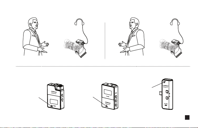
Please keep face to face when use it, and don’t turn your back to the receiver, otherwise it is easy to generate
breakpoints.
Face to receiver (correct)
Don't block the antenna position to avoid any poor signal generated.
Antenna position
Antenna position
Back to receiver (incorrect)
Antenna position
UC Receiver (UC RX)Receiver (RX)Transmitter(TX)
3
Page 6
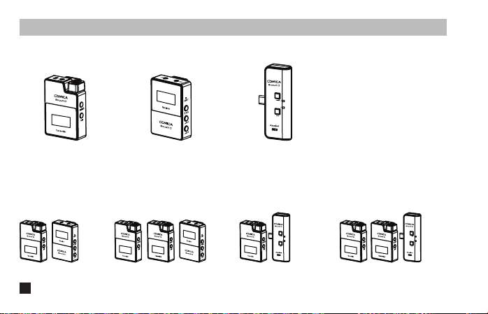
Packing List
Main Parts:
UC Receiver (UC RX)Receiver (RX) Transmitter(TX)
Multiple Selections:
D1 = TX + RX D2 = TX + TX + RX UC1 = TX + UC RX UC2 = TX + TX + UC RX
4
Page 7
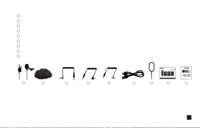
Accessories:
1
3.5mm Mic Audio Input Cable
2
Wind Mu
3
3.5mm TRS-TRRS Audio Cable (For Smartphone)
4
3.5mm TRS-TRS Audio Output Cable (For Canon, Nikon, etc.)
5
3.5mm TRS-TRS Audio Output Cable with Impedance(For Sony, Panasonic, Fujifilm, etc.)
6
USB A-USB C Charging Cable
7
Reset Pin
8
User Manual
9
Warranty Card
21
The accessories of each combination include:
① + ② + ③ + ④ + ⑤ + ⑥ + ⑦ + ⑧ + ⑨
D1=
①x2 + ②x2 + ③ + ④ + ⑤ + ⑥ + ⑦ + ⑧ + ⑨
D2=
① + ② + ⑥ + ⑦ + ⑧ + ⑨
UC1=
①x2 + ②x2 + ⑥ + ⑦ + ⑧ + ⑨
UC2=
2.4G Digital 1-Trigger-2 Wireless Microphone
User Manual
7 8 96543
5
Page 8
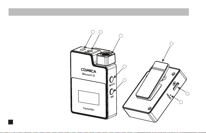
Transmitter (TX)
1. External Mic Locking Buckle
2. 3.5mm TRS Port of External Mic
3. Internal Mic
4. Power/Muting Button
5. Pair Button
6. Belt Clip
7. USB-C Charging Port
8. Reset Hole
6
Components and Instruction
2
1
3
4
5
6
7
8
Page 9
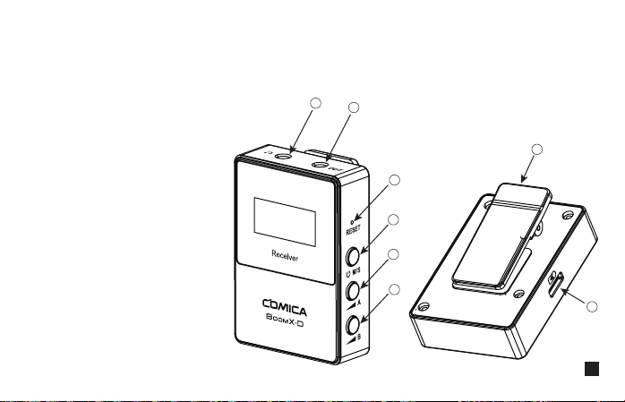
Receiver (RX)
1. 3.5mm TRS/TRRS Monitoring Port
2. 3.5mm TRS Audio Output Port
3. Reset Hole
4. Power and M/S Button
5. A Channel Output Gain Control Button
6. B Channel Output Gain Control Button
7. Belt Clip
8. USB-C Charging Port
1
2
7
3
4
5
6
8
7
Page 10
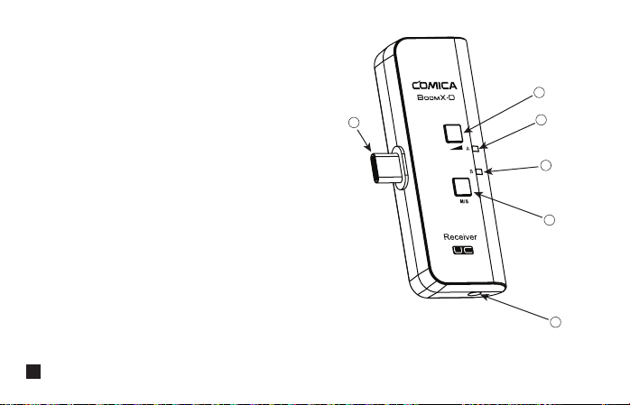
UC Receiver (UC RX)
1. USB-C Connector
2. Output Volume Adjustment Button
3. Group A Working Status Indicator
4. Group B Working Status Indicator
5. M/S Adjustment Button
6. 3.5mm TRS/TRRS Monitoring Port
8
2
1
3
4
5
6
Page 11
Installation
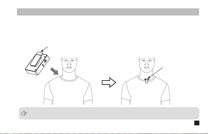
Transmitter (TX)
1.Use internal microphone :
Install the transmitter on the collar through the belt clip so that the internal microphone points in the direction
of the sound source.
Belt Clip
Internal Mic
For better concealment during use, it is recommended that the belt clip be fixed and used outwards.
9
Page 12
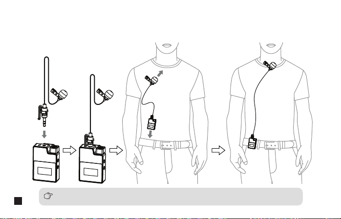
2.Use external microphone:
Insert the 3.5mm TRS microphone input cable into the transmitter's 3.5mm TRS external microphone port and
tighten it, then clip the transmitter to the belt through the belt clip and clip the lavalier microphone to your
collar.
10
When using an external microphone, the internal microphone is automatically turned o.
Page 13
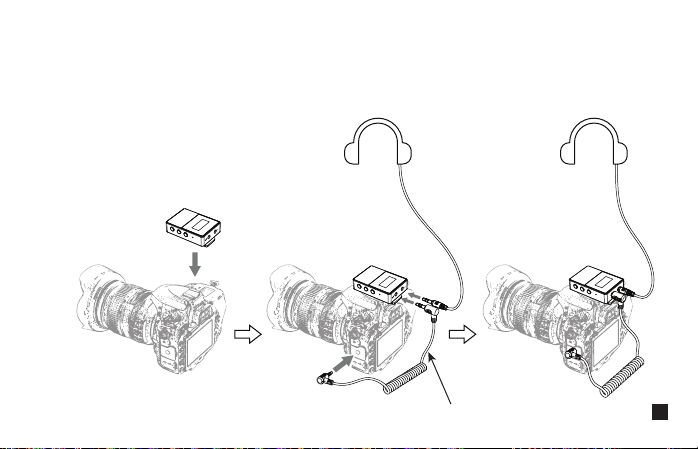
Receiver (RX)
1.Work with Camera:
Fix the receiver through the belt clip to the camera's hot shoe mount, then connect the receiver with camera
through the 3.5mm TRS-TRS audio cable; Insert the headphone into the monitoring port for monitoring.
3.5mm TRS-TRS Audio Cable
11
Page 14
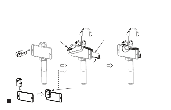
2.Work with Smartphone:
Clip the receiver to the cold shoe mount through the belt clip; Connect the receiver with the mobile phone
through the 3.5mm TRS-TRRS audio cable and pay attention to the access to the audio output jack of the
receiver is the 3.5mm TRS plug, and the access to the mobile phone is the 3.5mm TRRS plug; Insert the
headphone to the 3.5 mm TRS/TRRS monitoring port for monitoring.
TRS Plug
12
3.5mm TRS-TRRS Audio Cable
TRRS Plug
In the absence of a mobile phone holder, the receiver can be
clamped to the mobile phone through the belt clip, and the
installation methods of other accessories are the same as
above.
Page 15
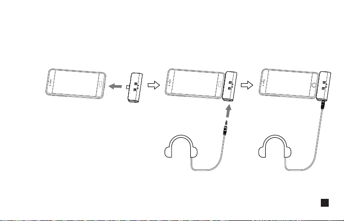
UC Receiver (UC RX)
Insert the UC receiver (UC RX) into the USB-C port of the phone; Insert the headphone into the 3.5mm
TRS/TRRS monitoring port for monitoring.
13
Page 16
Transmitter (TX)
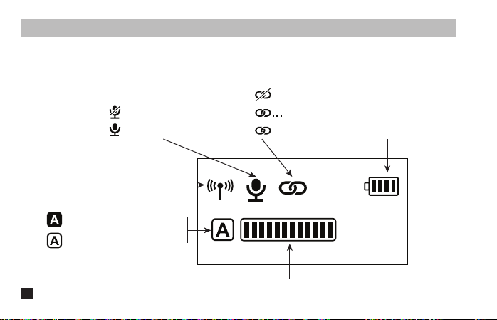
1.Screen Display Instruction:
Muting
Microphone Normal Working
Signal Strength
A/B Channel is Connected
A/B Channel is not Connected
Function and Usage
Unpaired
in the Pairing
Paired
Transmitter Battery Status
14
A/B Channel Microphone Audio Dynamic Bar
Page 17

2.Function Introduction:
2.1. Power/Muting Button
Long press for On/O; Short press for muting switch( Muting switch is available only when the screen is on,
if the screen is dimmed, press any button to light up the screen then switch the mute).
2.2. Pair Button
Long press for pairing with receiver (Pairing switch is available only when the screen is on, if the screen is
dimmed, press any button to light up the screen then pairing).
2.3. USB-C Charging Port
Connect the transmitter with the power through the USB A-USB C charging cable to charge.
15
Page 18

2.4. Reset Hole
If there is an abnormal phenomenon such as the device is crash or unable to turn on it, then insert the reset
pin into the reset hole to reset it.
2.5. 3.5mm TRS Microphone Port
Insert the 3.5mm TRS microphone input cable, and you can use the external lavalier microphone for
recording. At this time, the internal microphone of this device is turned o.
16
Page 19
Receiver (RX)
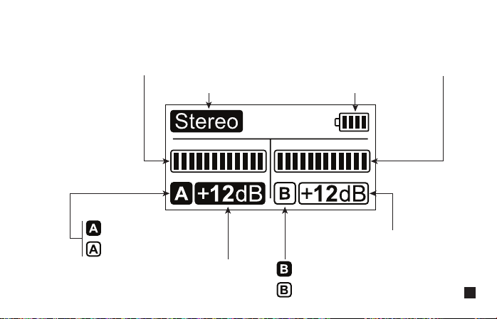
1.Screen Display Instruction:
A Channel Microphone Audio Dynamic Bar B Channel Microphone Audio Dynamic Bar
Mono/Stereo Receiver Battery Status
A channel is connected
A channel is not connected
Group A Output Volume
Group B Output Volume
B channel is connected
B channel is not connected
17
Page 20

2.Function Introduction:
2.1. Reset Hole
If there is an abnormal phenomenon such as the device is crash or unable to turn on it, then insert the reset
pin into the reset hole to reset it.
2.2. Power and M/S Button
Long press for On/O; Short press for mono and stereo mode switch. Please attention that it can not realize
STEREO function when in one-trigger-one mode.
(Mono/Stereo switch is available only when the screen is on, if the screen is dimmed, press any button to
light up the screen then switch the M/S)
2.3. A/B Channel Output Volume Adjustment Button
Short press to cyclically adjust the A/ B channel output Volume. It can independently adjust even in the
mono mode and is generally adjusted to the consistent output Volume when in use. (The output Volume
adjustment is available only when the screen is on, and if the screen is dimmed, press any button to light
up the screen and then adjust again).
18
Page 21

2.4. USB-C Charging Port
Connect the receiver with the power through the USB A-USB C charging cable to charge.
2.5. 3.5mm TRS Audio Output Port
Connect with mobile phone through the 3.5mm TRS-TRRS audio cable; Connect with camera through the
3.5mm TRS-TRS audio cable (3.5mm TRS-TRS Audio Output Cable with Impedance is recommended to
be used if there is sound explosive in recording ).
2.6. 3.5mm TRS/TRRS Monitoring Port
Insert headphone to monitor.
19
Page 22

UC Receiver (UC RX)
Function Introduction:
1. USB-C Plug
Insert into the USB-C port of phone to use.
2. Output Volume Adjustment Button
Short press to cyclically adjust the Volume, and A/B channel is synchronized.
3. M/S Button
Short press for Mono/Stereo switch. Please attention that it can not realize STEREO function when in
one-trigger-one mode.
20
Page 23

4. A/B Working Status Indicator
The indicator is red when unpaired. After paired, the indicator is blue when it's Mono and is purple when it's
Stereo.
5. 3.5mm TRS/TRRS Monitoring Port
Insert headphone to monitor.
21
Page 24

Pairing Method
(All have been paired at the factory. If you need to re-pair, please follow the description)
One-trigger-one:
Turn on the transmitter and receiver within one meter, and then press the pair button for pairing when the
transmitter screen is highlighted.
The transmitter (TX) is pairing with the receiver (RX)
Transmitter (TX)
The screen icon changes from to after pairing
The microphone audio dynamic bar is available after pairing
22
Transmitter (TX)
Receiver (RX)
Receiver (RX)
Page 25

The transmitter (TX) is pairing with UC Receiver (UC RX)
Transmitter (TX)
The screen icon changes from to after pairing
Transmitter (TX)
UC Receiver (UC RX)
The channel indicator on the UC receiver
(UC RX) changes from red to blue or
purple after pairing
UC Receiver (UC RX)
23
Page 26

One-trigger-two:
Turn on the transmitter and receiver within one meter, and then long press the pair button of one transmitter to
pair the receiver when the transmitter screen is highlighted. After the pairing is successful, the receiver will
designate the first paired transmitter as channel A.Then long press the pair button of the second transmitter for
pairing, and the receiver will designate the second paired transmitter as channel B after the pairing is
successful.Channel A is the left channel, channel B is the right channel.
The first paired transmitter
Two transmitters (TX) are pairing with Receiver (RX)
(A channel )(Left channel) (A channel )(Left channel)
(B channel )(Right channel)
24
The second paired transmitter
Page 27

The first paired transmitter
Two transmitters (TX) are pairing with UC Receiver (UC RX)
(A channel)(Left channel )
The second paired transmitter
(A channel)(Left channel )
(B channel)(Right channel)
25
Page 28

Transmitter (TX)
Specification
Wireless Band
Transmitting Power
Receiving Sensitivity
Antenna
Polar Pattern
Frequency Response
Sound Delay
External Mic Input Interface
Battery
Battery Life
Net Weight
Dimension
26
Operating Temperature
2400 ~ 2483.5MHz
+10dBm
-86dBm
PCB Antenna
Omnidirectional
80Hz ~ 20kHz
<20ms
3.5mm TRS
Built-in Li-ion Battery 300mAh 3.7V
5 Hours
29g
39 x 22 x 55mm
0℃ ~ 50
℃
Page 29

Receiver (RX)
Wireless Band
Transmitting Power
Receiving Sensitivity
Antenna
Audio Output Amplitude
Sound Delay
Audio Output Interface
Monitor Interface
Battery
Battery Life
Net Weight
Dimension
Operating Temperature
2400 ~ 2483.5MHz
+10dBm
-86dBm
PCB Antenna
+0dB ~ +12dB
<20ms
3.5mm TRS
3.5mm TRS/TRRS
Built-in Li-ion Battery 300mAh 3.7V
5 Hours
29g
39 x 22 x 55mm
0℃ ~ 50
℃
27
Page 30

UC Receiver (UC RX)
Wireless Band
Transmitting Power
Receiving Sensitivity
Antenna
Audio Output Amplitude
Sound Delay
Data Interface
Monitoring Interface
Net Weight
Dimension
Operating Temperature
28
2400 ~ 2483.5MHz
+10dBm
-86dBm
PCB Antenna
+0dB ~ +12dB
<20ms
USB-C
3.5mm TRS/TRRS
19g
33 x 13 x 70mm
0℃ ~ 50
℃
Page 31

用户使用手册
2.4G数字无线一拖二麦克风
Page 32

Page 33

前 言
感谢您购买COMICA/科唛BoomX-D 2.4G无线麦克风。
为保证产品的顺畅使用,请在使用前严格阅读本说明书,并正确组装及操作。
产品主要功能
. 2.4G数字无线,全球通用频段
. 一拖二,两路发射一路接收
. 可视化电量,音频动态监控等屏显功能
. 内置和外置MIC两种输入方式
. 单声道/立体声,多输出选择
. 支持实时监听
. 高保真音质
. 自动跳频,传输稳定
. 低音频延迟<20ms
. 传输距离稳定高达50m
. 多功能背夹设计,小巧精悍
1
Page 34

注意事项
由于2.4G无线特性,使用时尽量保持面对面,避免背对的情况,否则容易产生断点,属正常现象
使用时避免任何物体遮挡天线位置,以免信号不良
一拖一模式下,立体声(STEREO)功能不可实现
3.5mm TRS-TRS音频连接线适用于佳能、尼康等收音灵敏度较弱的相机
3.5mm TRS-TRS阻尼音频连接线适用于索尼、松下、富士等收音灵敏度较强的相机
(如连接设备后出现声音过爆现象,此时建议使用3.5mm TRS-TRS阻尼音频连接线)
使用于手机上时,请将WIFI和蓝牙关闭,避免2.4G无线干扰
本产品属于高精密仪器类产品,请避免使用时掉落、碰撞或重击
请勿将本设备放置在热源或干扰源附近使用,如散热器、烤箱、WIFI热点或其它无线设备旁边
如拾音距离较近或于户外使用时,请套上麦克风防风毛,防止声音爆裂或降低风噪
不要在雨中或潮湿的环境中使用该设备,否则会有短路的危险
请在干燥环境中对该产品进行保存
2
Page 35

尽量保持面对面,避免背对的情况,否则容易产生断点。
面对面(正确)
使用时避免任何物体遮挡天线位置,以免信号不良。
天线位置
天线位置
背对(错误)
天线位置
UC接收器(UC RX)接收器(RX)发射器(TX)
3
Page 36

包装清单
主体:
UC接收器(UC RX)接收器(RX)发射器(TX)
搭配选择:
D1 = TX + RX D2 = TX + TX + RX UC1 = TX + UC RX UC2 = TX + TX + UC RX
4
Page 37

配件:
1
3.5mm 麦克风输入线
2
防风毛
3
3.5mm TRS-TRRS音频连接线(手机适配线)
4
3.5mm TRS-TRS音频连接线(适配佳能、尼康等相机)
5
3.5mm TRS-TRS阻尼音频连接线(适配索尼、松下、富士等相机)
6
USB A-USB C充电线
7
复位针
8
说明书
9
保修卡
21
每一个型号的配件包括:
① + ② + ③ + ④ + ⑤ + ⑥ + ⑦ + ⑧ + ⑨
D1=
①x2 + ②x2 + ③ + ④ + ⑤ + ⑥ + ⑦ + ⑧ + ⑨
D2=
7 8 96543
① + ② + ⑥ + ⑦ + ⑧ + ⑨
UC1=
①x2 + ②x2 + ⑥ + ⑦ + ⑧ + ⑨
UC2=
2.4G Digital 1-Trigger-2 Wireless Microphone
User Manual
5
Page 38

发射器(TX)
1. 外置麦克风插头卡扣
2. 3.5mm TRS外置麦克风插孔
3. 内置麦克风
4. 电源/静音按钮
5. 配对按钮
6. 背夹
7. USB-C充电插口
8. 复位孔
6
部件介绍及说明
2
1
3
6
4
5
7
8
Page 39

接收器(RX)
1. 3.5mm TRS/TRRS耳机监听插孔
2. 3.5mm TRS音频输出插孔
3. 复位孔
4. 电源/单声道和立体声切换按钮
5. A通道输出音量调节按钮
6. B通道输出音量调节按钮
7. 背夹
8. USB-C充电插口
1
2
3
4
5
6
7
8
7
Page 40

UC接收器(UC RX)
1. USB-C插头
2. 输出音量调节按钮
3. A通道工作状态指示灯
4. B通道工作状态指示灯
5. 单声道/立体声切换按钮
6. 3.5mm TRS/TRRS耳机监听插孔
8
2
1
3
4
5
6
Page 41

安装方法
发射器(TX)
1.使用内置麦克风:
把发射器通过背夹安装到衣领上,使内置麦克风指向音源方向。
背夹
内置麦克风
在使用过程中为了更好的隐蔽性,建议将背夹朝外固定使用。
9
Page 42

2.使用外置麦克风:
把3.5mm TRS麦克风输入线插入发射器的3.5mm TRS外置麦克风插孔并扣紧;把发射器通过背夹夹
到腰带上,再把另一头的领夹麦克风夹到衣领上。
10
当使用外置麦克风时,内置麦克风会自动关闭。
Page 43

接收器(RX)
1.搭配相机使用安装方法:
把接收器通过背夹夹到相机的热靴座固定;通过3.5mm TRS-TRS音频连接线连接接收器和相机;
把耳机插入耳机监听插孔进行监听。
3.5mm TRS-TRS音频连接线
11
Page 44

2.搭配手机使用安装方法:
把接收器通过背夹夹到冷靴座;通过3.5mm TRS-TRRS音频连接线连接接收器和手机,并注意接入接收器音
频输出插孔的是3.5mm TRS插头,接入手机端的是3.5mm TRRS插头;把耳机插入3.5mm TRS/TRRS耳机监听
插孔进行监听。
三节TRS插头
3.5mm TRS-TRRS音频连接线
四节TRRS插头
在没有手机支架的情况下可以把接收器通过背夹夹到手
机上使用,其他配件的安装方法与上相同。
12
Page 45

UC接收器(UC RX)
把UC接收器(UC RX)插入手机的USB-C插口;把耳机插入3.5mm TRS/TRRS耳机监听插孔进行监听。
13
Page 46

发射器(TX)
1.屏幕显示:
信号强度
A/B通道已连接
A/B通道未连接
功能与使用方法
静音
麦克风正常工作
未配对
配对中
已配对
发射器电池电量
14
A/B通道麦克风音频动态条
Page 47

2.功能介绍:
2.1. 电源/静音按钮
长按开机/关机,短按进行静音切换(静音切换必须在屏幕亮显时才可用,如果屏幕暗显,
请先按任何按键使屏幕亮显再进行静音切换)。
2.2. 配对按钮
长按与接收器进行配对(配对切换必须在屏幕亮显时才可用,如果屏幕暗显,请先按任何
按键使屏幕亮显再进行配对)。
2.3. USB-C充电插口
通过USB A-USB C充电线连接发射器与电源进行充电。
15
Page 48

2.4. 复位孔
如出现死机或开不了机等异常现象,使用复位针插入复位孔即可复位。
2.5. 3.5mm TRS麦克风插孔
插入3.5mm TRS麦克风输入线,即可使用外置领夹麦克风进行录音,此时本机的内置麦克风被
关闭。
16
Page 49

接收器(RX)
1.屏幕显示:
单声道
Mono:
立体声
Stereo: 接收器电池电量
A通道麦克风
音频动态条
A通道已连接
A通道未连接
A通道输出音量
B通道已连接
B通道未连接
B通道麦克风
音频动态条
B通道输出音量
17
Page 50

2.功能介绍:
2.1. 复位孔
如出现死机或开不了机等异常现象,使用复位针插入复位孔即可复位。
2.2. 电源/单声道和立体声切换按钮
长按开机/关机,短按进行单声道和立体声切换。一拖一模式下,立体声(STEREO)功能不可
实现(单声道和立体声切换必须在屏幕亮显时才可用,如果屏幕暗显,请先按任何按键使屏幕
亮显再进行单声道和立体声切换)。
2.3. A/B通道输出音量调节按钮
短按可循环调节A/B通道输出音量,即使在单声道模式下,A/B通道输出音量也是独立调节,使
用时一般调节为一致的输出音量(输出音量调节必须在屏幕亮显时才可用,如果屏幕暗显,请
先按任何按键使屏幕亮显再进行输出音量调节)。
18
Page 51

2.4. USB-C充电插口
通过USB A-USB C充电线连接接收器与电源进行充电。
2.5. 3.5mm TRS音频输出插孔
通过3.5mm TRS-TRRS音频连接线与手机进行连接;通过3.5mm TRS-TRS音频连接线与相机进行
连接(如连接设备后出现声音过爆现象,此时建议使用3.5mm TRS-TRS阻尼音频连接线)。
2.6. 3.5mm TRS/TRRS耳机监听插孔
插入3.5mm TRS/TRRS耳机即可监听。
19
Page 52

UC接收器(UC RX)
功能介绍:
1. USB-C插头
插入手机USB-C插口即可使用。
2. 输出音量调节按钮
短按可循环调节输出音量,A/B通道同步调节。
3. 单声道和立体声切换按钮
短按可单声道和立体声切换。一拖一模式下,立体声(STEREO)功能不可实现。
20
Page 53

4. A/B通道状态指示灯
未配对时亮红灯,配对成功后单声道亮蓝灯,立体声亮紫灯。
5. 3.5mm TRS/TRRS耳机监听插孔
插入3.5mm TRS/TRRS耳机即可监听。
21
Page 54

配对方法(出厂时均已配对,如需重新配对时可按如下描述操作)
一拖一的配对方法:
在一米范围内先把发射器与接收器打开,然后在发射器屏幕亮显的情况下长按配对按钮进行配对即
可。
发射器(TX)与接收器(RX)配对
配对成功后屏幕图标由 变成
22
发射器(TX)
发射器(TX)
接收器(RX)
配对成功后麦克风
音频动态条可用
接收器(RX)
Page 55

发射器(TX)与UC接收器(UC RX)配对
配对成功后屏幕图标由 变成
发射器(TX)
发射器(TX)
UC接收器(UC RX)
配对成功后UC接收器(UC RX)的
通道指示灯由红色变成蓝色或紫色
UC接收器(UC RX)
23
Page 56

一拖二的配对方法:
在一米范围内先把发射器与接收器打开,然后在发射器屏幕亮显的情况下长按其中的一个发射器的
配对按钮进行配对,配对成功后接收器把最先配对的发射器定为A通道;再长按第二个发射器的配对
按钮进行配对,配对成功后接收器把第二个发射器定为B通道;A通道为左声道,B通道为右声道。
先配对的发射器
两个发射器(TX)与接收器(RX)配对
(A通道)(左声道)
24
后配对的发射器
(A通道)(左声道)
(B通道)(右声道)
Page 57

先配对的发射器
两个发射器(TX)与UC接收器(UC RX)配对
(A通道)(左声道)
(A通道)(左声道)
(B通道)(右声道)
后配对的发射器
25
Page 58

发射器(TX)
26
无线频段
发射功率
接收灵敏度
天线
麦克风指向性
麦克风频响
声音延迟
外置输入接口
电池
续航时间
净重
尺寸
工作温度
技术规格
2400 ~ 2483.5MHz
+10dBm
-86dBm
PCB天线
全指向
80Hz ~ 20kHz
<20ms
3.5mm TRS
锂聚合物 300mAh 3.7V
5小时
29g
39 x 22 x 55mm
0℃ ~ 50℃
Page 59

接收器(RX)
无线频段
发射功率
接收灵敏度
天线
音频输出幅度
声音延迟
音频输出接口
监听接口
电池
续航时间
净重
尺寸
工作温度
2400 ~ 2483.5MHz
+10dBm
-86dBm
PCB天线
+0dB ~ +12dB
<20ms
3.5mm TRS
3.5mm TRS/TRRS
锂聚合物 300mAh 3.7V
5小时
29g
39 x 22 x 55mm
0℃ ~ 50℃
27
Page 60

UC接收器(UC RX)
无线频段
发射功率
接收灵敏度
天线
音频输出幅度
声音延迟
数据接口
监听接口
净重
尺寸
工作温度
28
2400 ~ 2483.5MHz
+10dBm
-86dBm
PCB天线
+0dB ~ +12dB
<20ms
USB-C
3.5mm TRS/TRRS
19g
33 x 13 x 70mm
0℃ ~ 50℃
Page 61

Page 62

 Loading...