

Comfort Stat TOUCH ME 1 Owner's Manual
R
Reversing
Valve
Energized in
Cool Mode
Reversing
Valve
Energized in
Heat,
Emergency
Mode
Compressor
Contactor
Stage 1
Fan
Relay
Heat
Relay
Stage 2
Compressor
Contactor
Stage 2
Heat
Relay
Stage 1
*
Hot
120 VAC
Neutral
TRANSFORMER
(Class Current Limited)
24 VAC
Remote
Sensor
T2
T1
Thermostat Owners Manual
Model:TOUCH ME 1
Congratulations!
Your new thermostat will provide years of reliable service. By saving energy, your
thermostat will pay for itself during its first season of use. Thanks you for buying our
product!
Please read this manual for complete instructions on installing and operating your
thermostat. If you require further assistance, please feel free to contact us
IMPORTANT INFORMATION
1. This thermostat will NOT control 110/220V baseboard electric heating systems.
2. Temperature Range
This thermostat can be programmed between 41˚F and 95˚F (5˚C and 35˚C) in HEAT
mode, 45˚F and 99˚F (7˚C and 37˚C) in COOL mode. However, it will display room
temperatures from 32˚F to 99˚F (0˚C and 37˚C). “HI” will be displayed if the temperature
is higher than 99˚F (37˚C), and “LO” will be displayed if the temperature is lower than
32˚F (0˚C).
This thermostat will automatically cutoff in Heat mode if the temperature rises above
95˚F (35˚C), and automatically cutoff in Cool mode if the temperature drops below 45˚F
(7˚C).
3. Compressor Protection
This thermostat provides a 4 minutes delay after shutting off the cooling system before it
can be restarted. This feature will prevent damage to your compressor caused by rapid
cycling. It does not prevent a rapid compressor restart due to short power outages.
4. Battery Warning
Two fresh AAA alkaline batteries should provide well over one year of service. However,
when the batteries become drained, the Low Battery Indicator will flash on the display.
When this message occurs, install new alkaline batteries. Once the batteries have
become too low to ensure proper operation, your system will be turned off, and the
display will be cleared except for flashing Low Battery Indicator on the LCD display.
CAUTION: When only the Low Battery icon flashes on the display, the
thermostat is shut down, and your system will no longer operate.
In this condition, there is no temperature control of your
dwelling.
NOTE: The backlight will not function when the thermostat is in low battery condition.
NOTE: If you plan to be away from the premises over 30 days, we recommend that you
replace the old battery with new alkaline battery prior to leaving.
5.Power supply
The thermostat shall be powered by 24 VAC and with battery as backup.
FEATURES
Structure of thermostat and explanation for the LCD and keypad.
We are pleased you have selected one of our broad lines of wall thermostat. Our
products are manufactured to high quality standards and are designed for years of
service.
Read This Before Installing Thermostat
OPERATION
YOUR THERMOSTAT REPLACES
Description
Heat Pump (No Aux. or Emergency Heat) Yes
Heat Pump (with Aux. or Emergency Heat) Yes
Standard Heat & Cool Systems Yes
Two Stage Heat & Two Stage Cool Yes
Standard Heat Only Systems Yes
Millivolt Heat Only Systems– Floor or Wall
Furnaces
Yes
Standard Central Air Conditioning Yes
Gas or Oil Heat Yes
Electric Furnace Yes
Hydronic (Hot Water) Zone Heat-2 Wires Yes
Hydronic (Hot Water) Zone Heat–3 Wires No
NOTE: This Thermostat will NOT control 110/220Volt systems.
IMPORTANT
Read the entire installation section of this Owner’s Manual thoroughly before you begin
to install or operate your Thermostat.
This thermostat can be used for conventional or heat pump systems,
please configure the thermostat according to Configuration Menu
before operation.
INSTALLATION
What You Need
This thermostat includes two #8 slotted screws and four wall anchors for mountin g. To
install your controller, you should have the following tools and materials.
■ Slotted Screwdriver(s) ■ Small Philips screwdriver ■ Hammer
■ Electric drill and 3/16” bit ■ Two 1.5V (AAA) size alk aline battery (included)
CAUTION:
To prevent electrical shock and/or equipment damage, disconnect electric power
to system at main fuse or circuit breaker box until installation is complete.
Before removing wires from old thermostat's switching subbase, label each wire with the
terminal designation it was removed from.
1. Shut off electricity at the main fuse box until installation is complete. Ensure that
electrical power is disconnected.
2. Remove Old Thermostat: A standard heat/cool thermostat consists of three basic
parts:
a. The cover, which may be either a snap-on or hinge type.
b. The base, which is removed by loosening all captive screws.
c. The switching subbase, which is removed by unscrewing the mounting screws that
hold it on the wall or adaptor plate.
3. Remove the front cover of the old thermostat. With wires still attached, remove wall
plate from the wall. If the old thermostat has a wall mounting plate, remove the
thermostat and the wall mounting plate as an assembly.
4. Identify each wire attached to the old thermostat.
5. Disconnect the wires from the old thermostat one at a time. DO NOT LET WIRES
FALL BACK INTO THE WALL.
6. Install new thermostat using the following procedures.
WARNING
Does not use on circuits exceeding specified voltage. Higher voltage will damage
control and could cause shock or fire hazard. Do not short out terminals on gas
valve or primary control to test. Short or incorrect wiring will damage thermostat
and could cause personal injury and/or property damage.
Attach Thermostat Base to Wall
1. Remove the packing material from the thermostat. Gently pull the cover straight off the
base. Forcing or prying on the thermostat will cause damage to the unit.
2. Connect wires beneath terminal screws on base using appropriate wiring schematic
(see fig 4 through 6 and fig 1 ).
3. Place base over hole in wall and mark mounting hole locations on wall usin g base as
a template.
4. Move base out of the way. Drill mounting holes.
5. Fasten base loosely to wall, as shown in figs2 and figs3 . using four mounting screws.
6. Push excess wire into wall and plug hole with a fireresistant material (such as
fiberglass insulation) to prevent drafts from affecting thermostat operation.
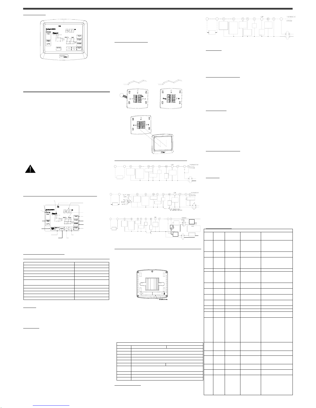
Figure 1. Wiring Diagrams Figure 2.Mounting Wallplate
Figure 3. Mount thermostat to wallplate
Wiring Diagrams
Figure 4.Typical wiring diagram for single transformer heat pump systems
Figure 5. Typical wiring diagram for two transformer heat pump systems with NO safety circuits
Figure 6. Typical wiring diagram for two transformer heat pump systems with safety circuits in
BOTH systems
Install AAA batteries
• The thermostat requires 2 AAA batteries to operate .
• Install 2 AAA alkaline batteries according to the polarity noted in the compartment. LCD
segments will go on.
NOTE: Replace the batteries when this LOW battery indicator appears on the display or
once a year.
Heat Pump Terminal Outputs
Refer to equipment manufacturers' instructions for specific system wiring information.
You can configure the thermostat for use with the following heat pump system types:
Single stage compressor system;
multiple stage compressor system; gas or electric
backup. This thermostat is designed to operate a single-transformer system. If you have
a two-transformer system, cut and tape off one transformer. If transformer safety circuits
are in only one of the systems, remove the transformer of the system with NO safety
circuits. If required, replace remaining transformer with a 75VA Class II transformer. After
disconnecting one transformer, the two commons must be connected together.
Use the terminal output information below to help you wire the thermostat properly for
your heat pump system. After wiring, see CONFIGURATION section for proper
thermostat configuration.
THERMOSTAT T ERMINALS (HEAT PUMP)
SYSTEM Heat Pump 1 Heat Pump 2
C* 24 Volt(Common)
R 24 Volt Emergency (hot)
E/W1 Emergency Mode 1st stage
W2 HP 1 and Emergency 2nd stage
Y1 Heat and Cool mode 1st stage (compressor)
Y2 No output 2nd stage compressor
G
Blower/Fan Energized on call for Heat and Cool
Set HE/HG in the FILT of the system menu
O Energized in Cool Mode
B Energized in Heat Emergency mode
L Malfunction
System mode operation
The System mode of the thermostat determines the Operating mode of the thermostat.
You may select COOL, OFF, HEAT, AUTO,EMER. In order to take full advantage of this
thermostat’s feature, we recommend using the AUTO mode. Refer to the Auto Season
Changeover information on Auto Season Changeover.
NOTE: Anytime you install or remove the thermostat form the wallplate,
change the System Mode to the OFF to prevent the possibility of a rapid
system On-Off.
Figure 7. Typical wiring diagram for single transformer multi-stage syst ems
Fan operation
The Fan mode should normally be chosen in the AUTO position. The Fan will be
turned on along with normal operation of your system. In a normal g as or oil furnace,
the Fan will not be open with the equipment. For electric heat, air conditioning, and
heat pump operation, the Fan will turn on with the system. To run the Fan on
continuously, change the Fan ON . Change the Fan Circ ,Fan runs randomly for
approximately 35% of schedule period when there is no call for cooling or heating
(programmable for all schedule periods).
Heating System(SPAN=2,SP2=2)
1. Press SYSTEM key to select the HEAT mode until HEAT shows on the LCD display.
2. Press to adjust thermostat setting to 2℉(1°C)above room temperature. The heating
system should begin to operate. The display should show “Heat On”. However, if the
“wait heat” is displaying and flashing, the compressor lockout feature is operating .
3. Adjust temperature setting to 4℉(2°C)above room temperature. If your system
configuration is set to “HP1” or “HP2”, the auxiliary heat system should begin to operate
and the display should show “AUX Heat On”.
4. When the room temperature above the thermostat setting, The heating system should
stop operating.
Emergency System
EMER bypasses the Heat Pump to use the heat source wired to terminal E/W 1 on the
thermostat. EMER is typically used when compressor operation is not desired, or you
prefer back-up heat only.
1. Press SYSTEM key to select the EMER mode. ,the “EMER” will show on the display.
2. Press to adjust thermostat setting to 2˚F(or 1℃) (SPAN) above room temperature.
The Aux. heating system will begin to operate. The display will show “Heat on”.
3. Adjust temperature setting to 4˚F(or 2℃) (SPAN+SP2) above room temperature. The
auxiliary heat system should begin to operate and the display should show “Aux Heat
on”.
4. Press to adjust the thermostat below room temperature. The heating system should
stop operating.
Cooling System(SPAN=2,SP2=2)
1. Press SYSTEM key to select the Cool mode.
2. Press to adjust thermostat setting below room temperature. The blower should come
on immediately, followed by cold air circulation. The display should show “Cool On”.
3. Adjust temperature setting to 4℉(2°C)below room temperature. The second stage
cooling should begin to operate.
4. When the room temperature below the thermostat setting. The cooling system should
stop operating.
Auto System
When the System Selector is in AUTO position , the thermostat will automatically
change between Heating and Cooling systems, depending on your setpoint. We
recommend keeping your programmed heating and cooling temperature at least 2 ˚F
(1˚C) apart to allow the Auto Season Changeover to occur when the appropriate
temperature span has been reached. However, if your heating and cooling programs set
temperatures are close, there is a built-in program to prevent the thermostat is in
Temporary, a Design ated Day Override or Permanent Override, as these overrides are
energy saving settings.
For example, you may have the following temperatures programmed at a given time:
Heat Set Temp=68˚F, Cool Set Temp=78˚F
If the room temperature rises above 78˚F, then the thermostat will automatically change
to cool mode and turn on the air conditioner.
Likewise, the thermostat will automatically change to heart mode and turn on heat when
the room temperature falls below 68˚F.
CONFIGURATION MENU
INSTALLER/CONFIGURATION MENU
Step Press
Button
Displayed
(Factory
Default)
Press up or
down key to
select
Comments
1 BLANK Std2 SS1, HP1,HP2
Selects Single stage,
Multi-stage, or Heat Pump
(Single stage or 2-stage)
System Configuration
2 BLANK RECO(OF) ON
Recovery function ON or
OFF
3 BLANK SPAN(2) 1,3
Span(one stage)
1-1F(0.5°C)
2-2F(1°C)
3-3F(1.5°C)
4 BLANK BLIT(ON) OF Backlight
5 BLANK SP2(2) 1,3
Span(2-stage)
1-1F(0.5°C)
2-2F(1°C)
3-3F(1.5°C)
6 BLANK CF(F) C
Selects temperature display
° F or °C
7 BLANK HOUR(12) 24
Selects time format display
12hours or 24hours
8 BLANK COHP(ON) OF
Selects Compressor
Lockout OFF or ON
9 BLANK CANL(0) -5~5
Adjust parameter of
temperature
10 BLANK FAN(HE) HE、HG Select HE or HG
11 BLANK COOL(2) 1 Affect Y1 Y2 output
12 BLANK FACT(0) 1
Select 1,all the setting will
go back to factory default
13 BLANK FILT(0)
1、2、3、4、5、
6
filter change reminder
0- filter change reminder off
1-10 run time days
2-30 run time days
3-60 run time days
4-90 run time days
5-120 run time days
6-365 run time days
14 BLANK UL(0) 1
0-UV lamp replacement
reminder off.
1-365 calendar days.
15 BLANK PROG(4) 0
0-nonprogrammable
4- 7 days programmable
16 BLANK LOCK(0) 1、2
0-unlocked keypad
1-partially locked keypad
2-fully locked keypad
17 BLANK HLIT(95F) 41-95F
41-95-temperature range (1°F
increments) of heating set-point.
18 BLANK CLIT(45F) 45-99F
45-99-temperature range (1°F
increments) of cooling set-point.
19 BLANK TEST(0) 1、2、3
test for relay
0:only B or O output
1:W1、W2、G、B or O output
2:Y1、Y2、O、G output
3:Y1、Y2、B、G output
Reversing
Valve
Energized in
Cool Mode
Reversing
Valve
Energized in
Heat,
Emergency
Mode
2nd Stage
Compressor
Fan
Relay
Emergency
Heat
Relay
Compressor
Contactor
Aux
Heat
Relay
Hot
120 VAC
Neutral
TRANSFORMER
(Class II Current Limited)
24 VAC
T1
T2
Remote
Sensor
SYSTEM
MONITOR
SWITCH
Reversing
Valve
Energized in
Cool Mode
Reversi ng
Valve
Energized in
Heat,
Emergency
Mode
2nd Stage
Compressor
Fan
Relay
Emergency
Heat
Relay
Compressor
Contactor
Aux
Heat
Relay
T1
T2
Remote
Sensor
Limit or
Safety
Switche s
Limit or
Safety
Switche s
HOT
120 VAC
24 VAC
Limit or Safety
Switc hes
COMMON
HOT
120VAC
24VAC
Limit or
Safety
Switche s
NEUTRAL
NEUTRAL
TWO COMMONS MUST
BE JUMPERED TOGETHER!
SYSTEM
MONITOR
SWITCH
The accessory relay scheme
is required when safety
circuits ezist in both systems
Auxiliary Heating
Transformer
(Class II Current
Limited)
24VAC
Accessory
Relay N.O.
Contacy
COMMON
Reversing
Valve
Energized in
Cool Mode
Reversing
Valve
Energized in
Heat,
Emergency
Mode
2nd Stage
Compressor
Fan
Relay
Emergency
Heat
Relay
Compressor
Contactor
Aux
Heat
Relay
Hot
120 VAC
Neutral
TRANSFORMER
(Class Current Limited)
24 VAC
Limit or Safety
Switches
T1
T2
Remote
Sensor
SYSTEM
MONITOR
SWITCH
days of the week
indicates the current
system temperature
locks out the screen
to allow for cleaning
the AUTO , ON will display
when the AUTO, ON is on
enter into the scheduling mode
save the current setting and quit the display mode
lowers temperature setting
sets a permanent hold and
activates vacation hold
sets the time
forward or back
display current time of day, hold
time remaining or number of
vacation days remaining
show the current
setting temperature
programming times
enter into the system
menu and modify the
program days
The COOL, HEAT OFF
AUTO OR EMER will
display when the COOL,
HEAT OFF AUTO OR
EMER is on
review total filter usage
raises temperature setting
The configuration menu allows you to set certain thermostat operating characteristics to
your system or personal requirements. Set SYSTEM switch to OFF, then press the
BLANK key in the left for 3 seconds to enter
configuration menu. The display will show the first
item in the configuration menu. The configuration
menu table summarizes the configuration options.
An explanation of each option follows .Press the
blank key to change to the next menu item. To exit
the menu and return to the program operation,
press DONE Key.
1) The display indicates “STD2” (default for multi-stage mode) in the displa y. Select the
system “SS1”,”HP1” or “HP2” by pressing the up or down key. In “SS1” and “STD2”
configuration, EMER mode is useless.
2) Select Energy Management Recovery OFF or ON
Your thermostat is set “OF” from the factory. You can select “ON” to g radually recover the
room temperature from an energy saving program to your comfort program. Therefore,
the thermostat may turn your system on several minutes prior to your programmed start
time.
Auto Recovery calculates how early to turn you system back on, so that the room
temperature is already comfortable by the start of the comfort temperature program
period. Auto Recovery work’s in both Heat and Cool modes.
3) Fast or Slow Cycle Selection (one stage).
4) Select Backlight function OFF or ON.
5) Fast or Slow Cycle Selection (2-stage).
6) Select °F or °C Readout. When you change this parameter, the programming come
back to default. You have to set the programming again.
Changes the display readout to Centigrade or Fahrenheit as required.
7) Selects time format display 12hours or 24hours.
8) Select Compressor Lockout COMP OFF or ON.
Selecting COMP ON will cause the thermostat to wait 4 minutes before turning on the
compressor if the heating and cooling system loses power. It will also wait 4 minutes
minimum between cooling and heating cycles. This is intended to help protect the
compressor from short cycling. Some newer compressors already have a time delay
built in and do not require this feature. Your compressor manufacturer can tell you if the
lockout feature is already present in their system. When the thermostat compressor time
delay occurs it will flash the set point for about four minutes.
9) You can adjust the parameter to calibrate the temperature.
10) This thermostat is configured from the factory to operate an electric heat or
heat-pump system that requires the thermostat to turn on the fan on a call for heat. If you
system is a heat/cool, fossil fuel (gas, oil, etc.), forced air system, select the HG. The
HE/HG must be set to match the type of Auxiliary heat your s ystem uses for proper
operation in the EMERGENCY mode. When FAN is set to HE, the type of Auxiliary heat
is an electric furnace, When FAN is set to HG, the type of Auxiliary heat is a gas furnace
or an oil burner.
11) This model must select 2
12) This model select 1 to back factory default.
13) Filter Change Reminder.
14) UV Lamp Change Reminder
15)
Select nonprogrammable or programmable
16) Unlocked all functions are available. Partially locked only Temperature up and down
keys and ability to enter and modify Installer Setup mode are available. Fully locked onl y
ability to enter and modify-Installer Setup mode are available.
17)
Max temperature range of heating set-point
18) Min temperature range of cooling set-point
19) Test for relay
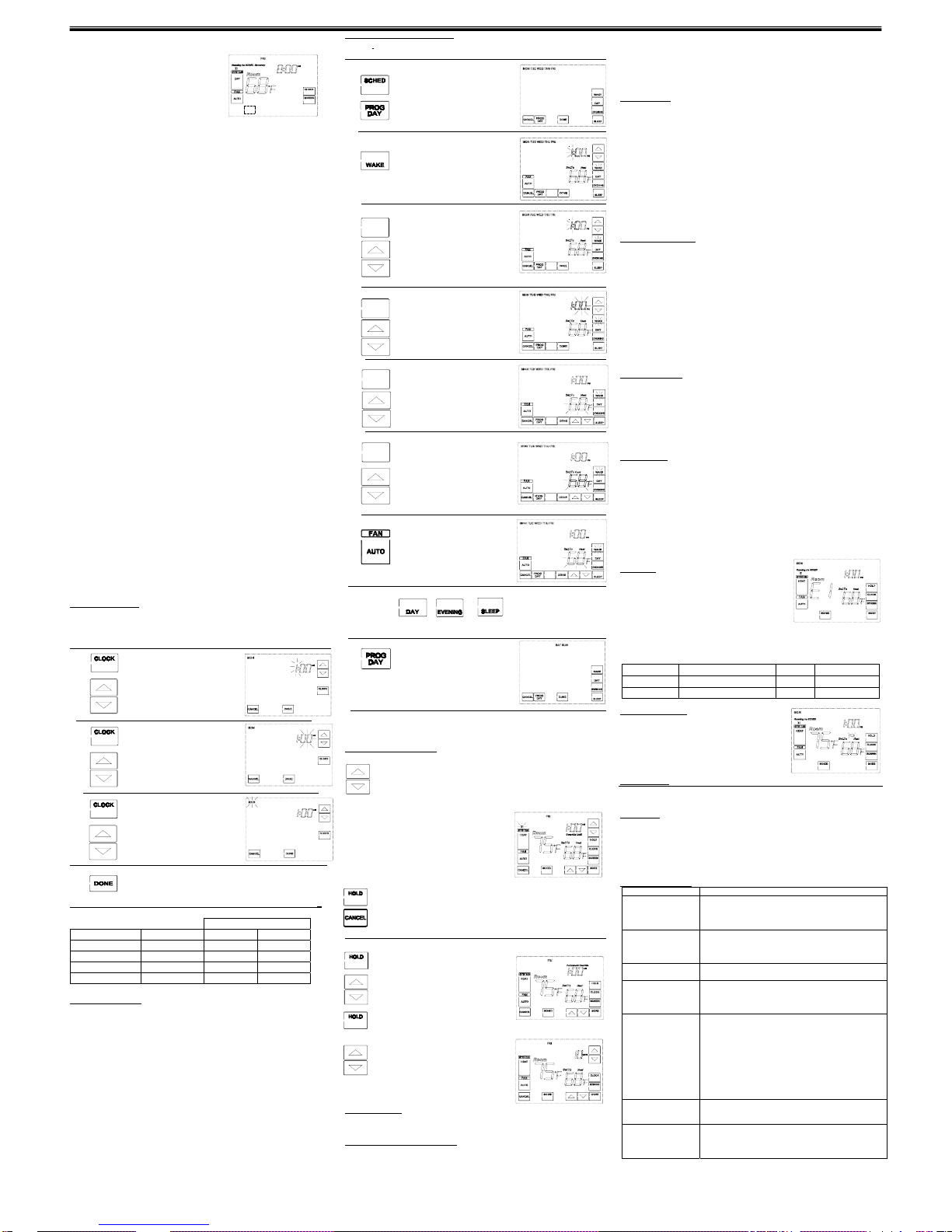
Setting Time And Day
Remove the mylar label covering the LCD display window before operating thermostat.
■ Initial display after power-up. The temperature will update after a few seconds.
■ During time and day setting mode , the temperature will disappear.
Press Display Reads
Step 1 ■Press CLOCK key. The current hour
and AM or PM indicator are flashing.
■Press up and down keys until right
hour appears on display.
Note AM/PM
Step 2 ■Press CLOCK key again.
The current minute are flashing.
■Press up and down keys until
right minute appears on display.
Step 3 ■Press CLOCK key.
The current week are flashing.
■Press up and down keys until
right week appears on display.
Step 4
■Press DONE key. The display will back to normal.
Programming
The following time and temperature settings are pre-programmed into the thermostat:
Temperature in ˚F (˚C)
Program Number Time Heat Cool
1 6:00 am 68˚F(20˚C) 78˚F(26˚C)
2 8:00 am 60˚F(16˚C) 85˚F(29˚C)
3 4:00 pm 68˚F(20˚C) 78˚F(26˚C)
4 10:00 pm 60˚F(16˚C) 82˚F(28˚C)
yAll 7 days of the week have the same default programs.
Manual Programming
■ Your thermostat can be programmed for weekdays and weekends, or have unique
programs for all 7 days. Use Weekday /Weekend Programs or 7-day Programming to
enter or revise programs to match your Personal Program Schedule. The same steps
are used when entering programs for the first time.
■ Familiarize yourself with Manual Programming, so that you can easily modify your
programs as your comfort needs change. The example below demonstrates the Manual
Programming method.
NOTE:
1,The program time can be set in 10-minute increments, and remains the same for both
Heat and Cool programs.
2,The program temperature can be set in increments of 1˚F (1˚C).
3,The Heat setpoint can not be set higher than the Cool set poi nt, and the Cool set point
can not be set lower than the Heat set point.
4,When setting the program time, note the AM/PM indicator.
5,With the Auto Recovery feature enabled, you do not need to set your comfort pro gram
times early. Auto Recovery will determine how early Recovery will determine how early
to turn your system on, so that the room is comfortable at the program time.
Weekday/Weekend Programming
Weekday
Programs
Press Display Reads
Step 1 ■Press SCHED key Enter into the
Programming mode
■ Press PROGDAY key Selects days
Mon to Fir for same set of 4 programs
each day.
■Mon to Fir is displayed.
Step 2 ■Press WAKE key Normal display of
time, temperature,and day of the
week
Step 3 ■ Program indicator(1) is displayed.
■The Program hour are flashing.
■Press UP or DOWN key to change the
hour.
Note AM/PM
Step 4 ■Press BLANK key again to change
to the minute position. The period
minute will be flashing.
■ Press UP or DOWN key to change
the minute
Step 5
■Press BLANK key again to change
to the program HEAT set temperature.,
the period program will be flashing.
■Press UP or DOWN key to change
the temperature.
■ Note HEAT/COOL
Step 6
■Press BLANK key again to change
to the program COOL set temperature.
The period program will be flashing.
■Press UP or DOWN key to change
the temperature.
■ Note HEAT/COOL
Step 7
■ Press FAN key to change the
FAN mode
Weekday program 1 is complete.
Step 7 ■ Press or or to move to program 2 or 3 or 4
and follow the same steps.
■Selects weekend days Sat, Sun for
same set of 4 programs each weekend
day.
■ Follow steps 2-7 to enter programs.
NOTE: Another approach to programming is to first program all weekdays Mon
through Fir and Sat and Sun as same programs. Then, display and change the
programs of only those days which will have different programs.
Temporary Manual Override
To temporarily change the current set temperature without affecting your program:
■Press Up or Down key for less than 1 second to check Setpoint..
■Press Up or Down to change to your desired
New temperature.
■Press Up or Down to change to your desired
reaching time
■The current program number will flash to
signify the Temporary Override. At the next
program change, the Temporary Override is
canceled, and the next program temperature
becomes the set point temperature To end
the Temporary Manual Override:
How to exit the temporarily mod e ?
■Press HOLD key and wait for Permanent Override to display on the lcd.
■Press CANCELkey,T his will return the set temperature to the current program
set temperature.
Permanent Override or a Designated Day Override
To hold your Manual Override for vacation or Until a Designated Day.
■ Press HOLD key to make the current program
temperature the HOLD temperature.
Permanent Override will be displayed on the
LCD, and the Program number will disappear.
■ Follow the Temporary Manual Override
Instructions above to change the Permanent
Manual Override temperature.
■Press HOLD key again. Hold day will be
displayed on the LCD and the clock will
disappear
■Press up key to increase override days.
■Follow the Permanent Override instructions
above to change the a Designated Day
Manual Override temperature.
To end Override:
Under Permanent Override Press CANCEL key . Under a Designated Day Override
press CANCEL key. The thermostat will return to the current program..
Clean Thermostat Screen
The thermostat has a touch screen interaction. Follow these steps to clean the screen
without making thermostat parameter changes:
1. Press the SCREEN key. Thermostat locks out all touch keys
for 30 seconds to allow
for cleaning.
2. Use damp cloth slightly moistened with water or house- hold glass cleaner to clean
the screen.
3. Repeat the above steps, as necessary.
IMPORTANT
Do not spray any type of liquid directly on the thermostat itself. If using household glass
cleaner, spray cleaner on cloth. Then use a cloth to clean the thermostat screen.
4. Press the DONE key to return to the Home Screen and normal operation.
Screen Lockes
1.Partially Locked Screen
When partially locked, the screen indicates Screen Locked for 2 to 4 seconds whenever
the user attempts to press a key that is locked. Pressing a locked key, while Screen
Locked is shown, flashes “Screen Locked” on the screen.
In this mode, all keys are locked except the Temperature Up and Down arrow keys:
User can change temperature Up or Down but cannot change schedule settings.
Temporary temperature change lasts until next scheduled period and that time
shows on screen.
To cancel temperature override and begin following schedule, press CANCEL key.
To unlock screen, see CONFIGURATION MENU
2.Fully Locked Screen
In this mode, all keys are locked and not functional. To unlock screen, see
CONFIGURATION MENU.
Filter Change Reminder
The filter change reminder must be turned on from the Installer Setup. Once expired,
the screen flashes CHANGE FILTER. Press the MORE key three seconds to reset
the change reminder.
NOTE: The days are counted as fan run time, so anytime the fan is running, the
reminder is counting that time against the number of days selected.
The remaining run time days can be viewed by pressing the MORE key; the
remaining days can be edited by using the MORE key. To view or reset the reminder
by following steps before it expires:
1. Press the MORE key until the filter reminder appears on the screen. This is the
number of fan run-time days remaining on the filter reminder.
2. Use the Up or Down keys to change the number of run-time days.
3. Press the DONE key to go back to the viewing screen.
UV Lamp Reminder
The UV Lamp change reminder must be turned on from the Installer Setup. Once
expired, the screen flashes, CHANGE UV Lamp appear. Press the MORE key three
seconds to reset the change reminder.
1. Press the MORE key until the UV Lamp change reminder appears on the screen.
This is the number of calendar days remaining on the UV Lamp reminder.
2 Use the Up or Down keys to change the number of calendar days.
3. Press the DONE key to return to the Home Screen.
Auto Recovery
Auto Recovery calculates how early to turn your system back on, so that the room
temperature is already comfortable by the start of the comfort temperature program
period. Auto Recovery work’s in both Heat and Cool modes.
■The “Recovery” will be displayed when the thermostat is in Auto Recovery mode, and
the program indicator will flash.
■ Auto Recovery can be disabled by menu setting.
■ Auto Recovery will not operate if Permanent hold or Temporary hold is in operation.
■ Auto Recovery can be canceled manually if HOLD key is pressed during the recover y
process.
Error Mode
If the thermostat is unable to control your system
due to an unexpected battery problem, thethermostat will
enter Error Mode. In this condition, the thermostat flashes
“E1”, “E2” or”E5”on the LCD display, and shuts off your
system. To correct this problem, replace the
battery with two new AAA alkaline battery, even if you have recently replaced them.
Move the battery out, and then hold any key to release the rest energy. Then place the
battery again. You will need to reprogram your thermostat and confirm normal operation.
If Error Mode returns, please call us for further information.
LCD displa
y
information LCD information
E1 Sensor Erro
r
E2 E2 memory Error
E5 System monitor switch Erro
r
Low Battery Warning
Your thermostat has a lower battery warning system.
When the batteries are first detected to be weak, the
low battery warning is indicated by battery symbol
flashing on the LCD display. At your earliest convenience,
you need to replace the batteries with 2 new AAA alkaline
batteries.
Remote Sensor
The internal sensor will be disable when terminal connect with remote sensor. The
internal sensor is default if there's no remote sensor connect with terminals.
Auto Cut Off
Your thermostat will automatically cut off in Heat mode if the room temperature rises
above 95˚F (35˚C). It will cutoff in Cool mode if the room temperature drops below
45˚F (7˚C).
Note that if your system has malfunctioned and no longer responds to thermostat
controls, the Auto Cut-Off function will have no effect.
TROUBLESHOOTING
Problem Solution
SCRAMBLED OR
DOUBLE DISPLAY
(numbers over
numbers)
1. Remove clear mylar sticker.
NO DISPLAY
1. Check batteries connections and battery.
2. Move the battery out, and then hold any key to release
the rest energy. Then place the battery again.
3. Replace Batteries.
ENTIRE DISPLAY
DIMS
1.Replace Batteries
PROGRAM DOES
NOT CHANGE AT
YOUR DESIRE
SETTING
1. Check that the time is set properly to “AM” or “PM”.
2. Check that the thermostat is not in “HOLD” mode.
3. Check for the correct day settings.
AUTO/FAN DOES
NOT TURN ON
1. select HG/HE in the SYSTEM MENU .
2. The thermostat may be in the AUTO Mode. Look for”
AUTO” on the LCD display. If the Heat and Cool program
temperature are close, then the thermostat requires a
larger room temperature change before changing from
Heat or Cool.
3. There may be as much as 4 minute delay before the
Heat or Cool system turns On-wait and check.
(Compressor protection delay).
4. Replace batteries.
ERRATIC DISPLAY
1. Move the battery out, and then hold any key to release
the rest energy. Then place the battery again.
2. Replace Batteries
THERMOSTAT
PERMANENTLY
READS
“E1”,”E2”
1. Replace unit.
If you experience any other problems, call us for technical assistance.
 Loading...