


CDT901
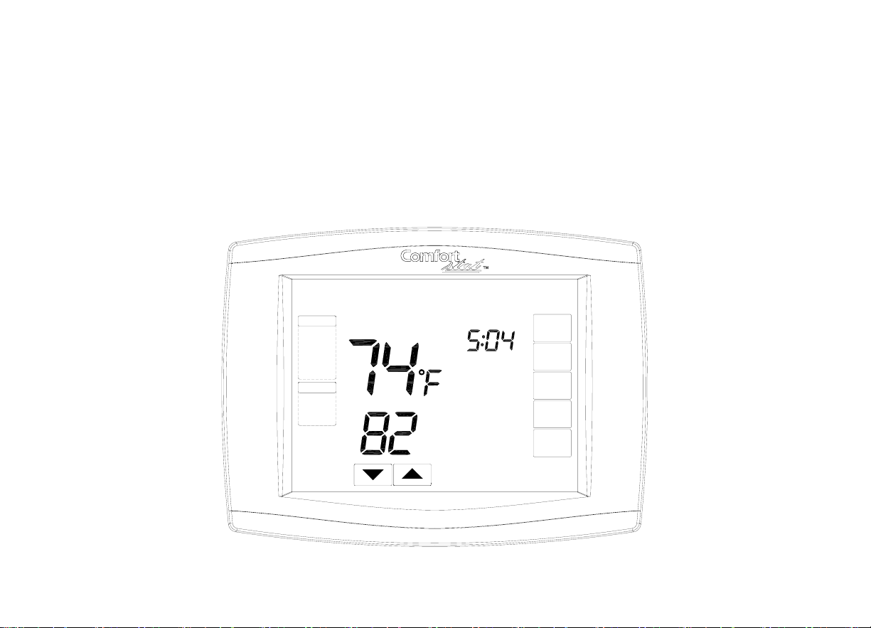
CDT900 Series Touchscreen
Programmable Thermostat
PM
Room
SCHED
HOLD
CLOCK
SCREEN
SYSTEM
FAN
MORE
AUTO
Running As SCHED
WED
COOL
Set To

CDT900 Series Touchscreen Pro
g
rammable Thermo
s
tat
a
Contents
Application/Features............................. ....... ........... ................. ................. ........................... 2
Specifications/Ordering Information ..................... ................. ................. ............................. 4
Installation ........................................................ .. ................. ...............................................13
Wiring ................................................................... ................. ................. ............................ 17
Power the Thermostat .................................. ................ ................. ..................................... 34
Installer Setup ............................. ................. ................ ...................................................... 47
Installer System Test ................. ................. ................ ........................................................ 59
Operation ............................. ................. ............... ............................................................... 62
Programming .................. ................. ................. .................................................................. 68
Troubleshooting ................ ................. ................. ................................................................ 97
1
`

PRODUCT DATA
APPLICATION
The CDT900 Series Touchscreen Programmable Thermostat is an effortless, 7-Day
programmable thermostat that provides universal system compatibility, precise comfort
control and is easy-to-program.
The CDT900 Series Thermostats provide temperature control for gas, oil, electric and heat
pumps for up to 3 heat, 2 cool systems including dual fuel operation plus dehumidification
control.
CDT900 Series Touchscreen Pro
g
rammable Thermo
s
tat
a
2

FEATURES
·Large, clear display with backlight shows the current and set temperature and
thermostat in the dark.
·Menu-driven programming make setup effortless.
·Beautiful ergonomic design is smart and sophisticated to match your custome
r
lifestyle.
·Touchscreen interaction
·Real-time clock keeps time during power failures and automatically updates to
daylight savings.
·"Saving Chan ges" notificat ion lets you know when the schedule ch anges have been
saved.
·Change/check reminders let you know when to service or replace filters or batteries
·Various Hold options allow you to override the program schedule, as desired.
·Armchair programming allows you to remove the thermostat from the wall fo
r
programming.
CDT900 Series T ouchscreen Pro
g
rammable Thermostat
a
3
CDT900 Series Touchscreen Pro
g
rammable Thermo
s
tat
a
SPECIFICATIONS
Thermostat Description:
Featre Description
Powering methods Common wire with battery bac ku p
System types (up to3 heat/2 cool)
·Gas, oil or electric heat with air conditioning
·Warm air, hot water, high-effic iency fur naces, heat
pumps, steam and gravity
·Heat on
ly inclu
des power to open and power to
close zone val v es ( series 20) and normally-open
zone valves
·Heat only with fan
·Cool only
·750 mV heating systems
Changeover Manual or Auto changeover selectable
System setting Heat-Off-Cool-Auto (Emer for heat pumps)
Fan setting Auto-On-Circ
4
CDT900 Series Touchscreen Pro
g
rammable Thermo
s
tat
a
Electrical Ratings:
Terminal
Voltage (50/60 Hz ) Running Cu rrent
W Heating 20 - 30 Vac 02 - 1.0A
W Heating (Powerpile) 750 mV dc 100 mA dc
Y Cooling 20 - 30 Vac .02 - 1.0A
G Fan 20 - 30 Vac 02 - .60A
Temperature Setting Range:
Heating: 40°F to 90°F(4°C to 32°C).
Cooling: 50°F to 99°F (10°C to 37°C).
Operating Am bient Temperature:
32°F to 120°F(0°C to 49°C).
Shipping Temperature:
CDT900 Thermostats: -30 °F to 150 °F
(-34.4°C to 65.6°C).
5

CDT900 Series Touchscreen Pro
g
rammable Thermo
s
tat
a
Operating Relative Humidity (Non-condensing):
CDT900 Series Thermostats: 5% to 90%.
IRS-1: 5% to 95%.
ORS-1: 5% to 95%.
Humidity Setting Range (CDT901 models only):
Cooling: 40% to 80% RH.
Humidity Display Range (CDT901 models only):
0% to 99%.
Cycle Rates (at 50% Load):
Heating: Selectable 1 - 12 cycles per hour.
Cooling: Selectable 1 - 6 cycles per hour.
Clock Accuracy: +/- 1 minute per month.
Batteries:
Two replaceable AA alkaline batteries: Power thermostats when 24 Vac common is not used.
Non-replaceable lithium battery with ten-year life under normal use to hold calendar and time
settings. Alkaline batteries keep calendar and time after lithium battery is no longe
r
functional.
6

CDT900 Series Touchscreen Pro
g
rammable T hermo
s
tat
a
Cool Indication:
CDT900 series Touchscreen Thermostats show "Cool On" on the screen when Cool is
activated.
Heat Indication:
CDT900 series Touchscreen Thermostats show "
Heat On
" on the screen when Heat is
activated.
7

CDT900 Series Touchscreen Pro
g
rammable T hermo
s
tat
a
ORDERING
INFORMATION
If you have additional questions, need further informatio n, or would like to comment on ou
r
products or services, please write or phone:
1. Smart Electric
Attn: Warranty Department
12201 NW 107th Ave
Miami, Fl 33178
2. Call Customer Service at 1-866-591-9898
Auxiliary Heat Indication:
CDT900 Touchscreen Thermostats show "
Au
x Heat On" on the screen when Auxiliary H eat
is activated.
Emergency Heat Indication:
CDT900 Touchscreen Thermostats show "
He
at On" on the screen when Emergency Heat is
activated and the System mode is in the Emer position.
Calibration:
CDT900 Touchscreen Thermostats are factory-calibrated and require no field calibration.
Nomenclature:
8

CDT900 Series Touchscreen Pro
g
rammable T hermo
s
tat
a
Series System Stages
Application
CDT900
CDT901
3H/2C CDT900 - Standard
CDT901-Humidity Sensor
Mounting Means:
CDT900 Series Touchscreen Thermostat: Mounts directly on the wall in the living space
using mounting screws and anchors provided.
Outdoor Sensor: Mounts outside of living space with mounting clip and screws provided.
Remote Indoor Sensor: Mounts directly on the wall using mounting screws and anchors
provided.
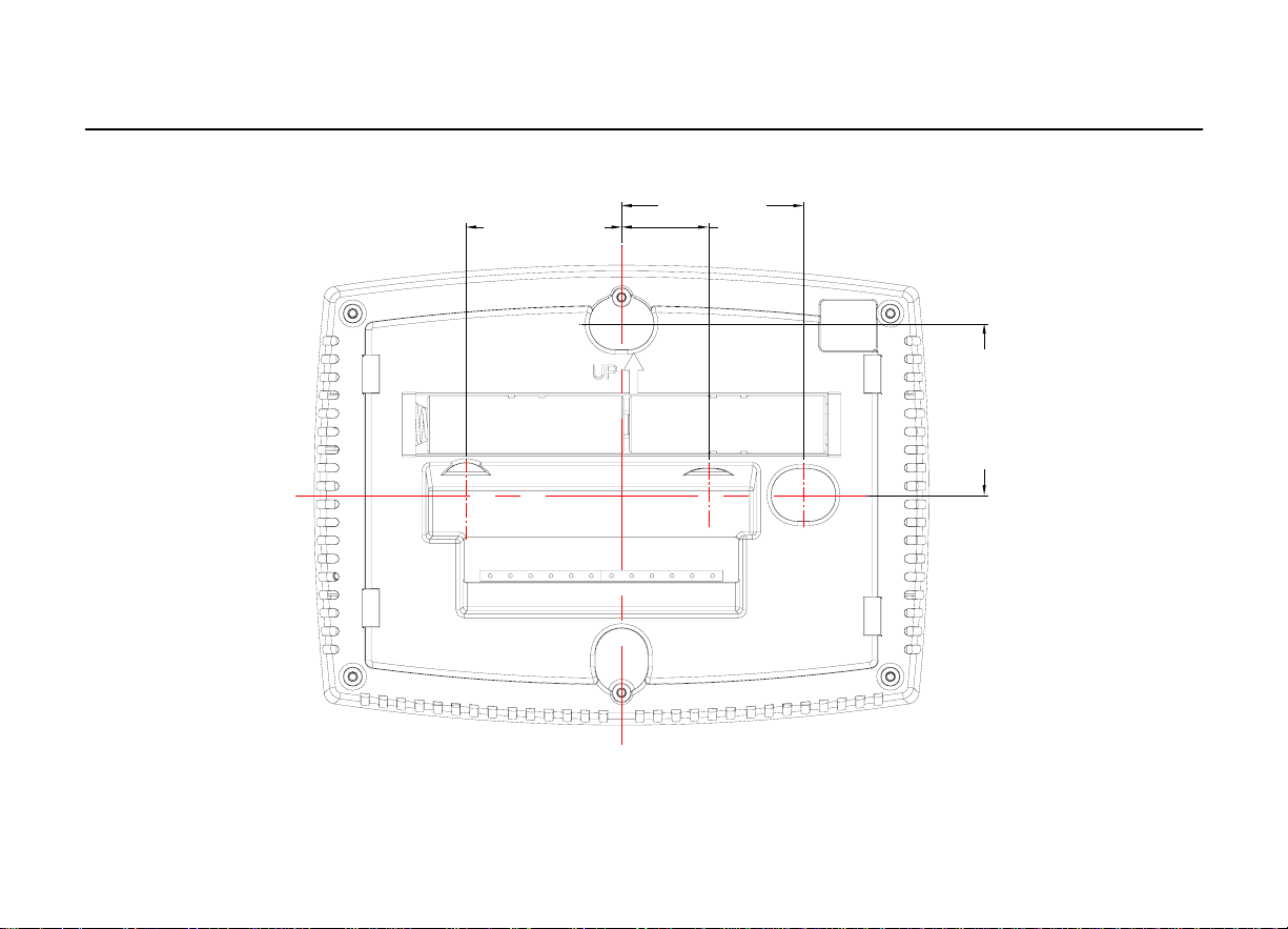
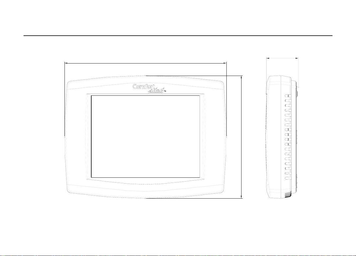
Dimensions:
CDT900 Series Touchscreen T h er m o s t at: see Fig 1.
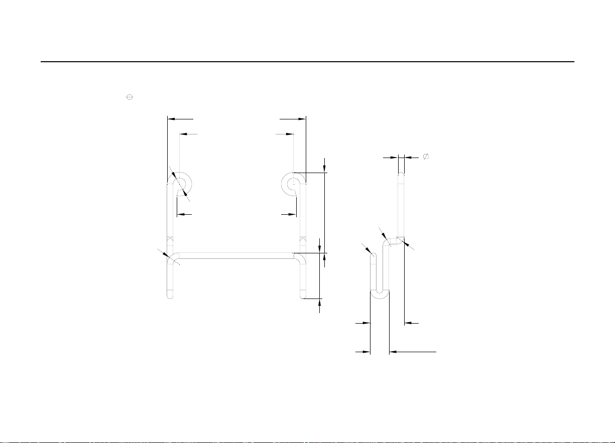
1. CDT900 Outdoor Sensor Mounti ng Clip: see Fig 2.
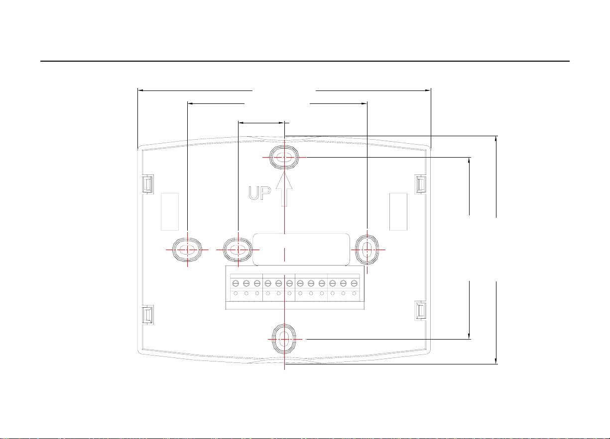
2. Cover Plate: see Fig 3.
3. CDT900 Series Remote Indoor Sensor: see Fig. 4
9
CDT900 Series Touchscreen Pro
g
rammable T hermo
s
tat
a
10
1.51 in.(38.5mm) 0.84 in .(21.5mm)
1.77 in.(45mm)
1.67 in.(42.5mm)
CDT900 Series Touchscreen Pro
g
rammable T hermo
s
tat
a
Fig. 1. Touchscreen Thermos
t
at dimensions in in. (mm).
11
1.17 in.(29.84mm)
5.98 in.(152mm)
4.48in. (114mm)
CDT900 Series Touchscreen Pro
g
rammable T hermo
s
tat
a
Fig. 2. Ou
t
door Sensor Mounting Clip dimensions in in. (mm).
1
2
1.49 in.(38mm)
0
.
1
7
i
n
.
(
4
.
2
m
m
)
R1
.
6
i
n
.
(
4
m
m
)
1.82 in.(46.3mm)
R
0
.
0
4
i
n
.
(
1
m
m
)
R
0
.
0
9
8
i
n
.
(
2
.
5
m
m
)
1.10 in.(28.1mm)
0.62 in.(16mm)
1.56 in .(39.7mm)
0.24 in.(6.2mm)
0.44 in .(11.2mm)
R
0
.
0
9
8
i
n
.
(
2
.
5
m
m
)
0.08 in.(2mm)
CDT900 Series Touchscreen Pro
g
rammable T hermo
s
tat
a
Fig. 3. Cover Plate dimensions in in. (mm).
13
3.29 in.(83.5mm)
0.85 in .(21.5mm)
3.29 in.(83.5mm)
5.35 in.(136mm)
4.13 in.(105mm)

CDT900 Series Touchscreen Pro
g
rammable T hermo
s
tat
a
INSTALLATION
When
Installing
this
Product...
1.Read these instructions carefully. Failure to follow the instructions can damage the product
or cause a hazardous con dition.
2.Check the ratings given in the instructions to make sure the product is suitable for you
r
application.
3.Installer must be a trained, experienced ser vic e technician.
4.After completing installation, use these instructions to check out the product operation.
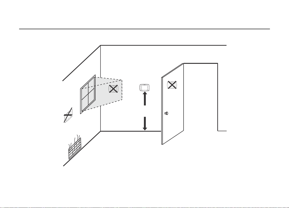
Selecting
Location
Install the thermostat about 5 ft. (1.5m) above the floor in an area with good air circulation at
average temperature. See Fig. 5.
Do not install the thermostat where it ca n be affected by:
----Drafts or dead spots behind doors and in corners.
----Hot or cold air from ducts.
----Radiant heat from sun or appliances. Concealed pipes and chimneys.
----Unheated (uncooled) areas such as an outsid e wall behind the thermostat.
14
CDT900 Series Touchscreen Pro
g
rammable T hermo
s
tat
a
Fig. 5. Selecting thermos
t
at location.
15
5FEET
1.5METERS

CDT900 Series Touchscreen Pro
g
rammable T hermo
s
tat
a
Installing
Wallplate
CAUTION
Electrical Hazard.
Can cause electrical shock or equipment damage.
Disconnect power before wiring.
The thermostat can be mou
n
ted horizont
a
lly on the w
a
ll
1.Position and leve l the wallplate (fo r appe arance only).
2.Use a pencil to mark the mounting holes.
3.Remove the wallplate from the wall and, if drywall, drill two holes in the wa ll, as marked. Fo
r
firmer material such as plaster, drill two holes. Gently tap anchors (provided) into the drilled
holes until flush with the wall.
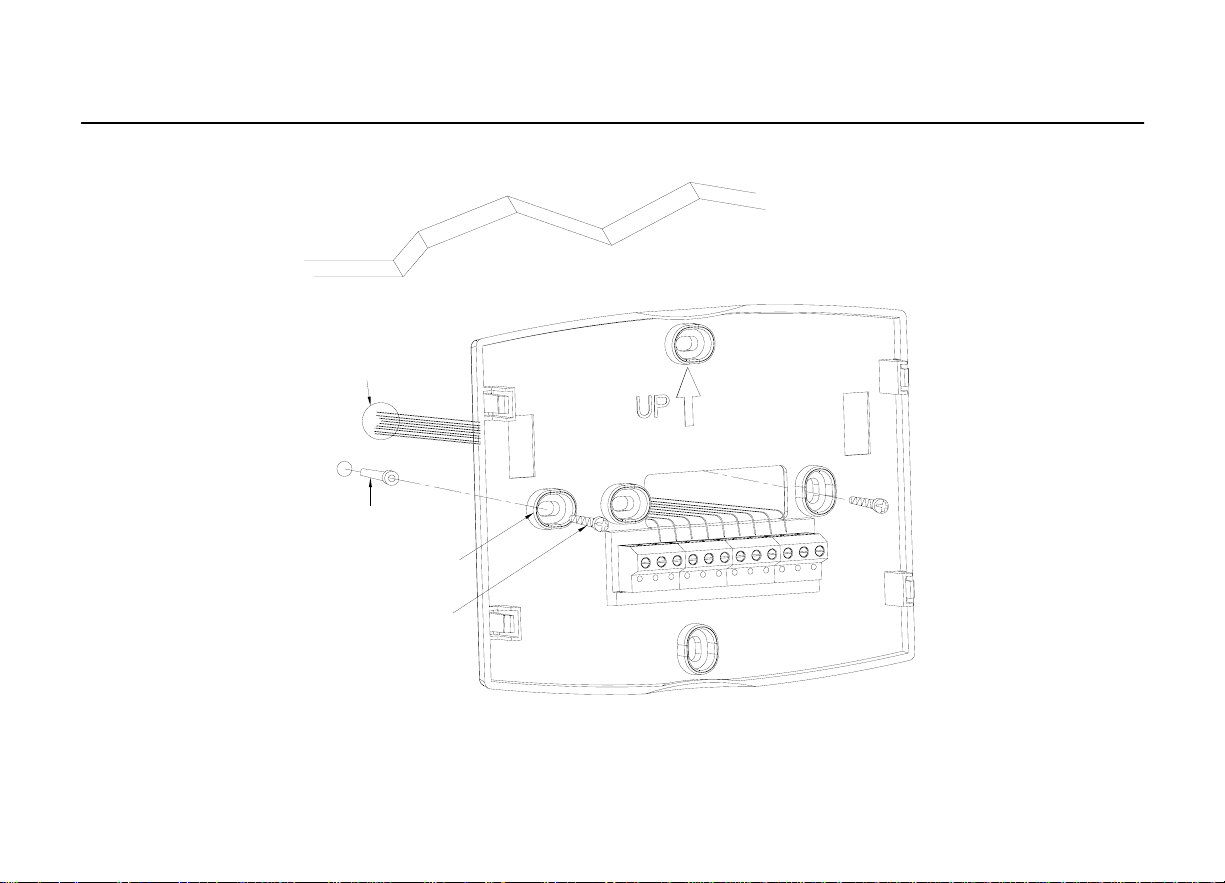
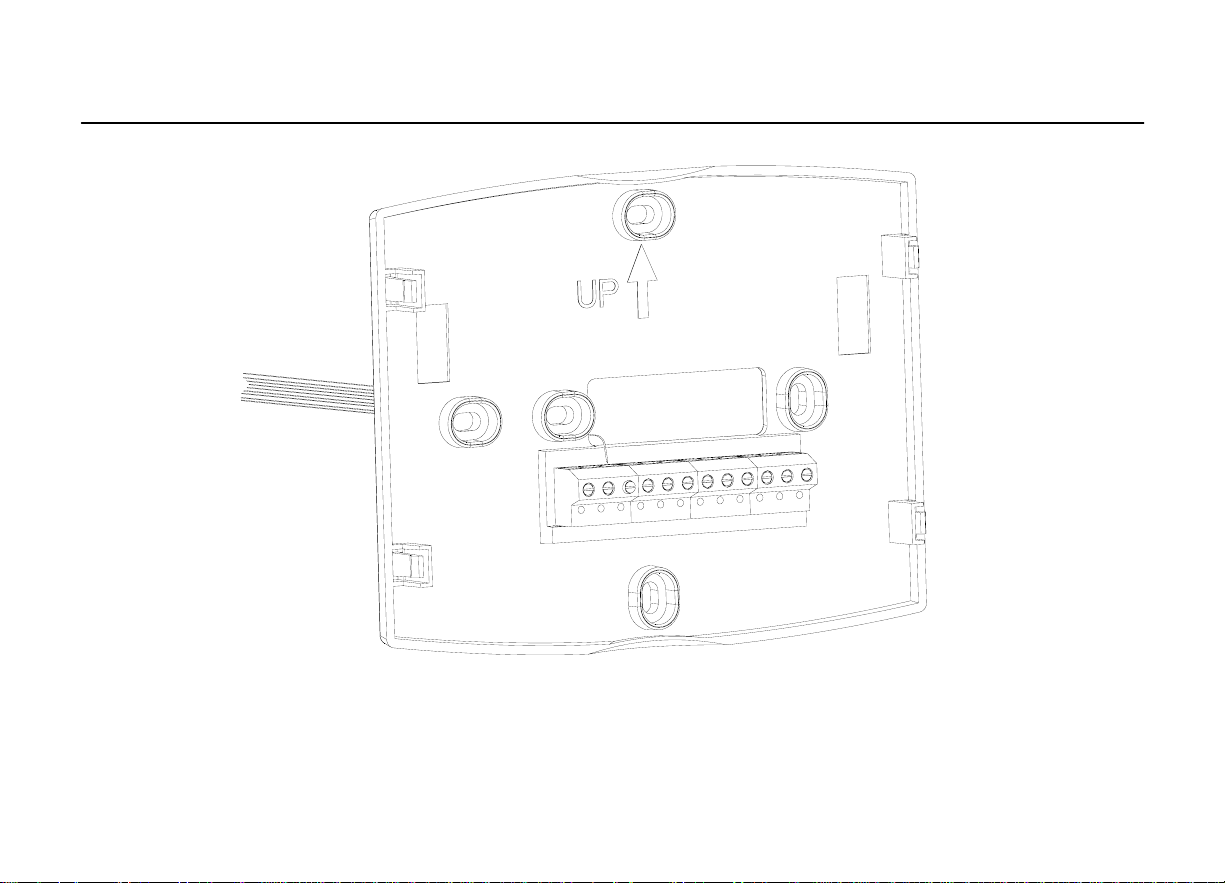
4.Position the wallplate over the holes, pulling wires through the wiring opening. See Fig. 6
5.Insert the mounting screws into the holes and tighten.
16
CDT900 Series Touchscreen Pro
g
rammable T hermo
s
tat
a
Fig. 6. Mounting wallplate.
17
WALL
WIRES THROUGH
WALL AND WIRE
SLOT
WALL ANCHORS
M0UNTING
HOLES(2)
M0UNTING
SCREWS(2)
CDT900 Series Touchscreen Pro
g
rammable T hermo
s
tat
a
WIRING
(FIG.
9
-
21)
A
ll wiring must comply wi th local electrical co des and ordinances.
1.Select set of terminal identifications (Table 1) that corresponds with system type
(conventional or heat pump in Fig. 7).
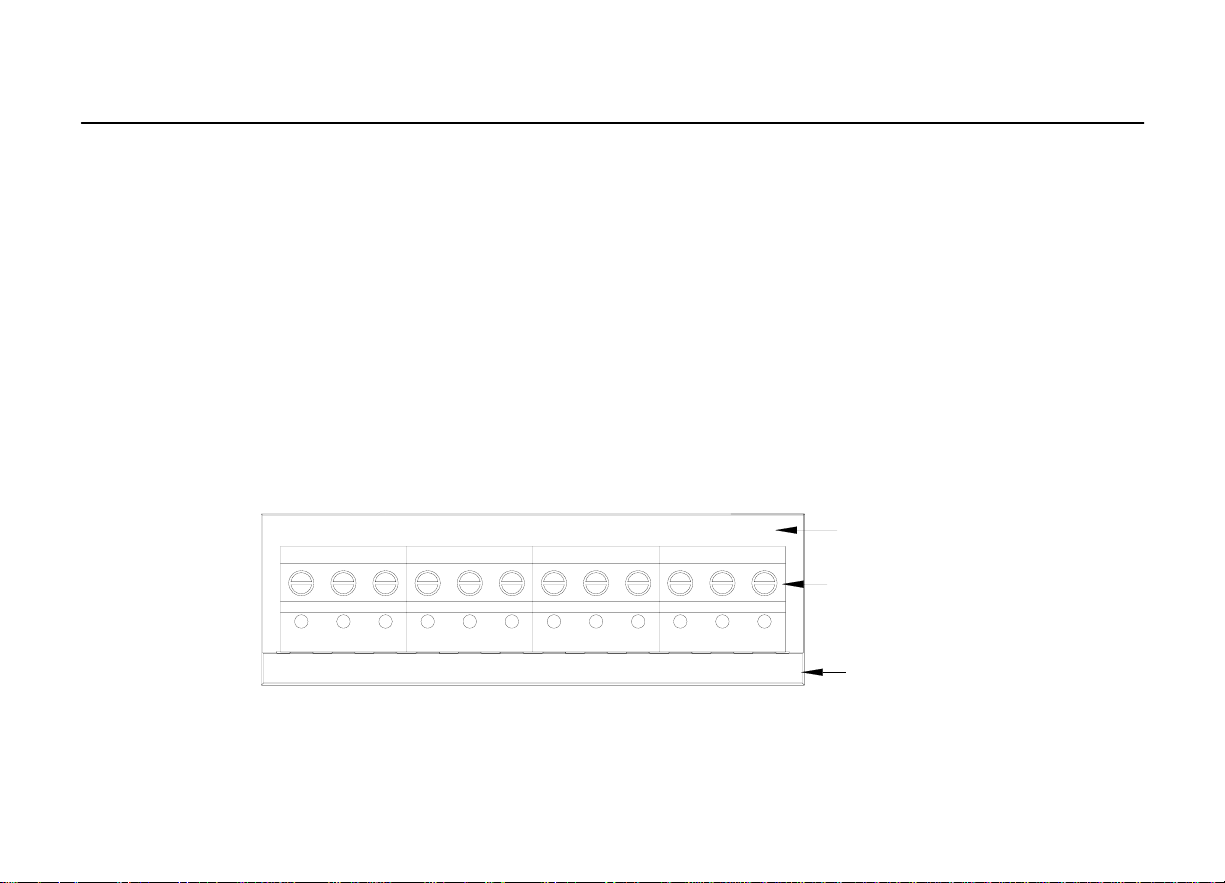
2.Loosen the screws for the appropriate system type selected; see Table 1. See T able 2 fo
r
terminal designation descriptions. Insert wires in the terminal block under the loosened
screw. See Fig. 8.
3.Securely tighten each screw.
4.Push excess wire back into the hole.
5.Plug the hole with nonflammable insulation to prevent drafts from affecting the thermostat.
6.See Fig. 9 through 21 for typical wiring hookups.
Fig. 7. Selecting terminal identifications for
system type.
18
CONVENTIONAL
HEAT PUMP
SCREW
TERMINALS
S1 S2 C R RC E L Y2 Y G
S1 S2 C R RC W W2 Y2 Y G
O/B AUX

CDT900 Series Touchscreen Pro
g
rammable T hermo
s
tat
a
Table 1. Select ing Terminal Identifications for System Type.
System Type
Wallplate Terminal
Identifications
Wirin g Diagram
Reference
Standard Heat/Cool Conventional
9, 10
Heat Only Conventional
11
Heat Only with Fan Conventional
12
Heat Only (Series 20) Power to open and
power to close zone valves
Conventional
13
Normally Open Zone Valves Heat Only
Conventional
14
Cool Only Conventional
15
Standard Multistage up to 2 Heat/2 Cool Conventional
16, 17
Heat Pump with No Auxiliary Heat Heat Pump
18, 19
Heat Pump with Auxiliary Heat Heat Pump
20, 21
19
CDT900 Series Touchscreen Pro
g
rammable T hermo
s
tat
a
IMPO
R
T
AN
T
:Use 18 gauge thermostat wire.
Fig. 8. Inserting wires in terminal block.
20

CDT900 Series Touchscreen Pro
g
rammable Thermo
s
tat
a
Table 2. Terminal Designation Descriptions.
Terminal Designation Description
Rc (see Note 1)
Power for cooling--connect to secondary side of cooling
system transformer
R (see Note 1)
Power for heating--connect to secondary side of heating
system transformer
C (see Note 2)
Common wire from secondary side of cooling system
transformer
W Heat relay
Y Compressor contactor
G Fan relay
Y2 Second stage cooling
W2 Second stage heat relay
O/B (see Note 3) Changeover valve for heat pump systems
AUX Auxiliary heat relay for heat pump systems
E Emergency heat relay for heat pump systems
L (see note 4) Equipment monitor for heat pump systems
S1, S2 Optional outdoor or indoor remote sensor
NOTES:.
1.When sed in a single-transformer system, leave metal jumper wire in place between Rc
and R. If used on a two-transformer system, remove metal jumper wire between Rc and R.
2.Common wire is optional when thermostat is used with batteries.
3. If thermostat is configured for a heat pump system in the Installer Setup, configure
changeover valve for cool (O -factory setting) or heat (B).
4.L terminal is an input (system monitor) when the System mo de is in the Heat, Off, Cool o
r
A
uto position. L terminal is a 24 Vac output when System mode is Emergency Heat. Must
connect the 24 Vac Common when using the L terminal. See LCD Indication section for more
details.
21
CDT900 Series Touchscreen Pro
g
rammable T hermo
s
tat
a
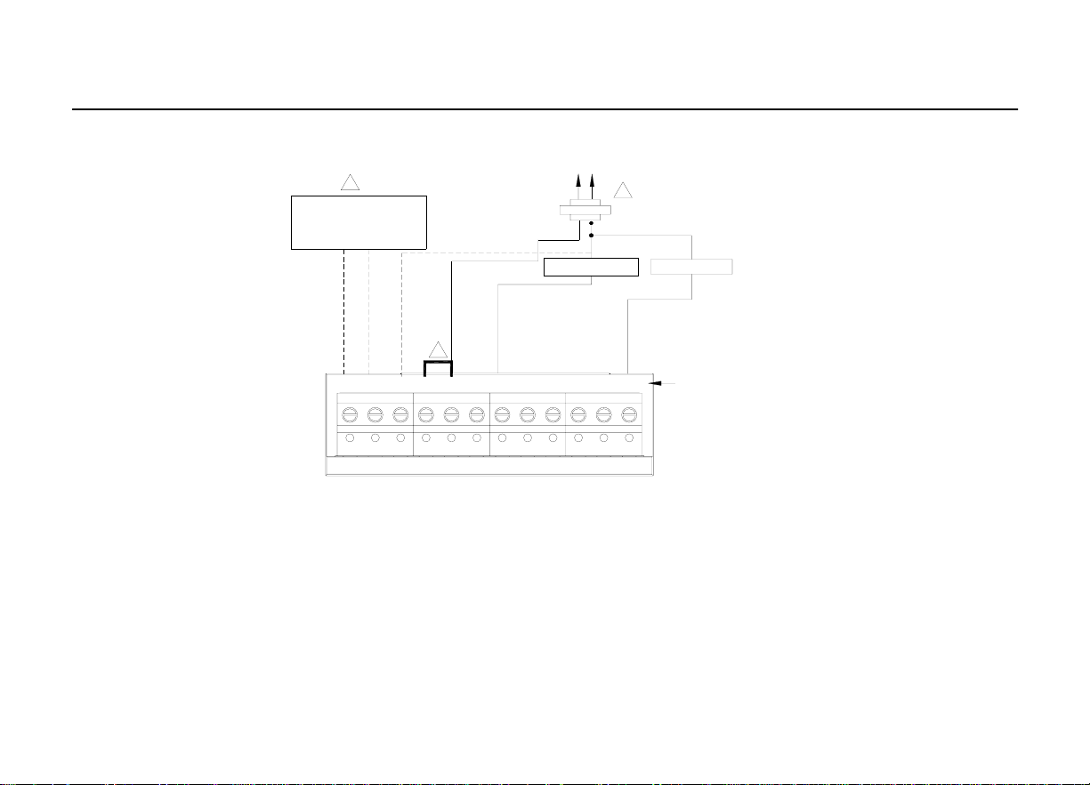
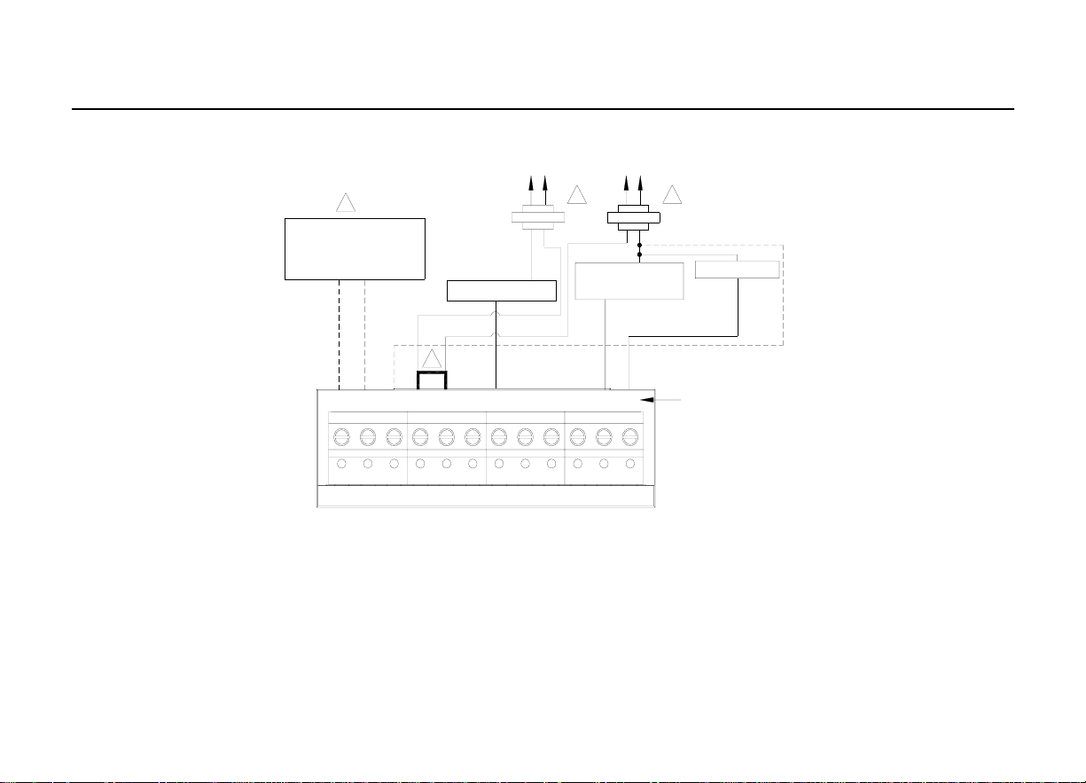
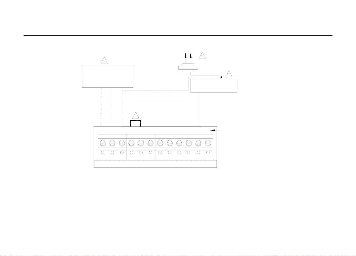
1.POWER SUPPLY. PROVIDE DISCONNECT MEANS AND OVERLOAD PROTECTION AS REQUIRED.
2. FACTORY INSTALLED JUMPER.
3.OPTIONAL OUTDOOR OR INDOOR REMOTE SENSOR. AVAILABLE ON SELECT MODELS. WIRES MUST HAVE A CABLE
SEPARATE FROM THE THERMOSTAT CABLE
Fig. 9. Typical hookup of conventional single-s
t
age heat and cool system with single
transformer(1H/1C conventional).
22
CONVENTIONAL
S1 S2 C R RC W W2 Y2 Y G
OUTDOOR/INDOOR
TEMPERATURE
SENSOR
3
HEAT RELAY
OPTIONAL
24VAC
COMMON
CONNECTION
R
C
1
2
FAN RELAY
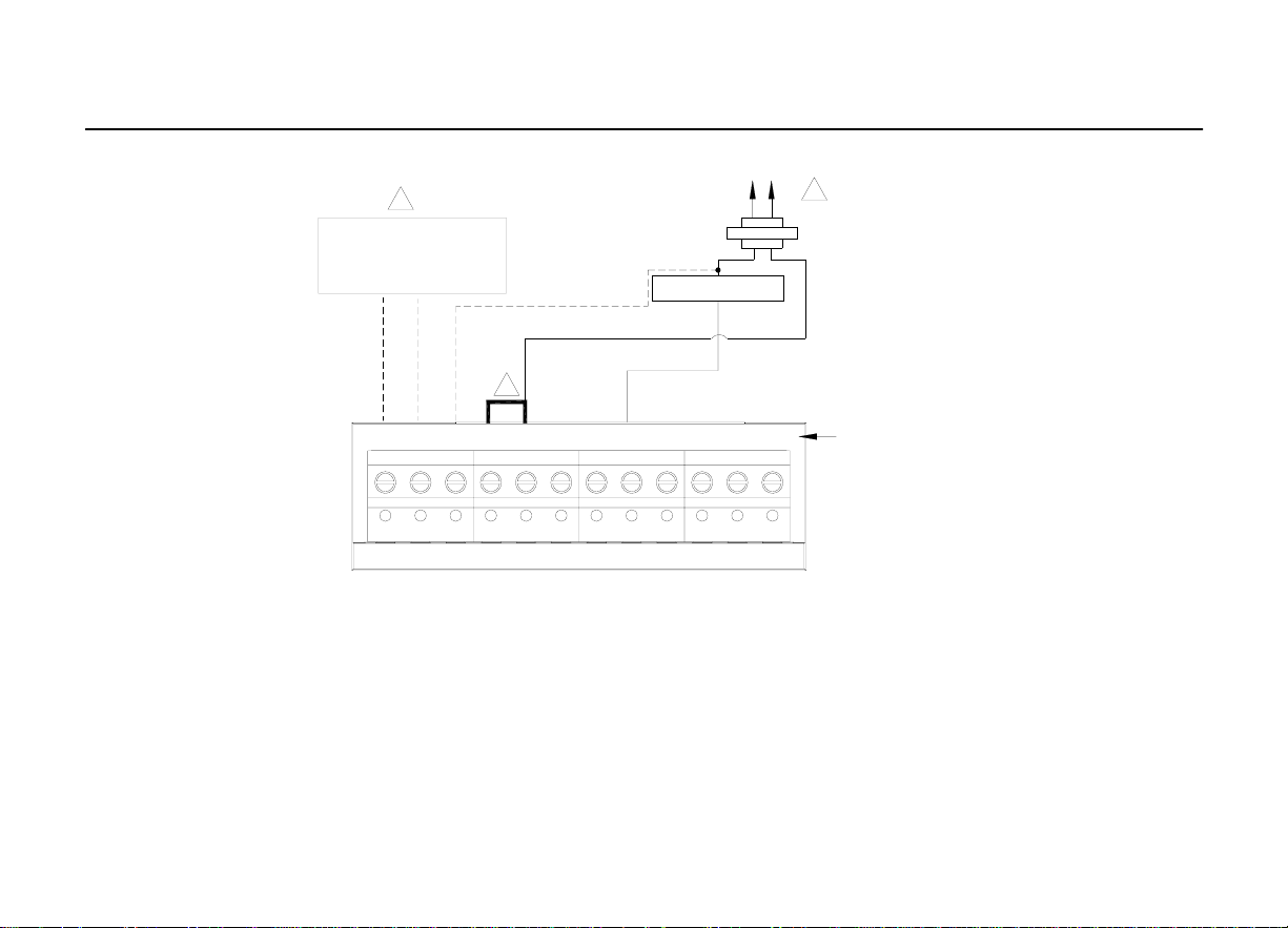
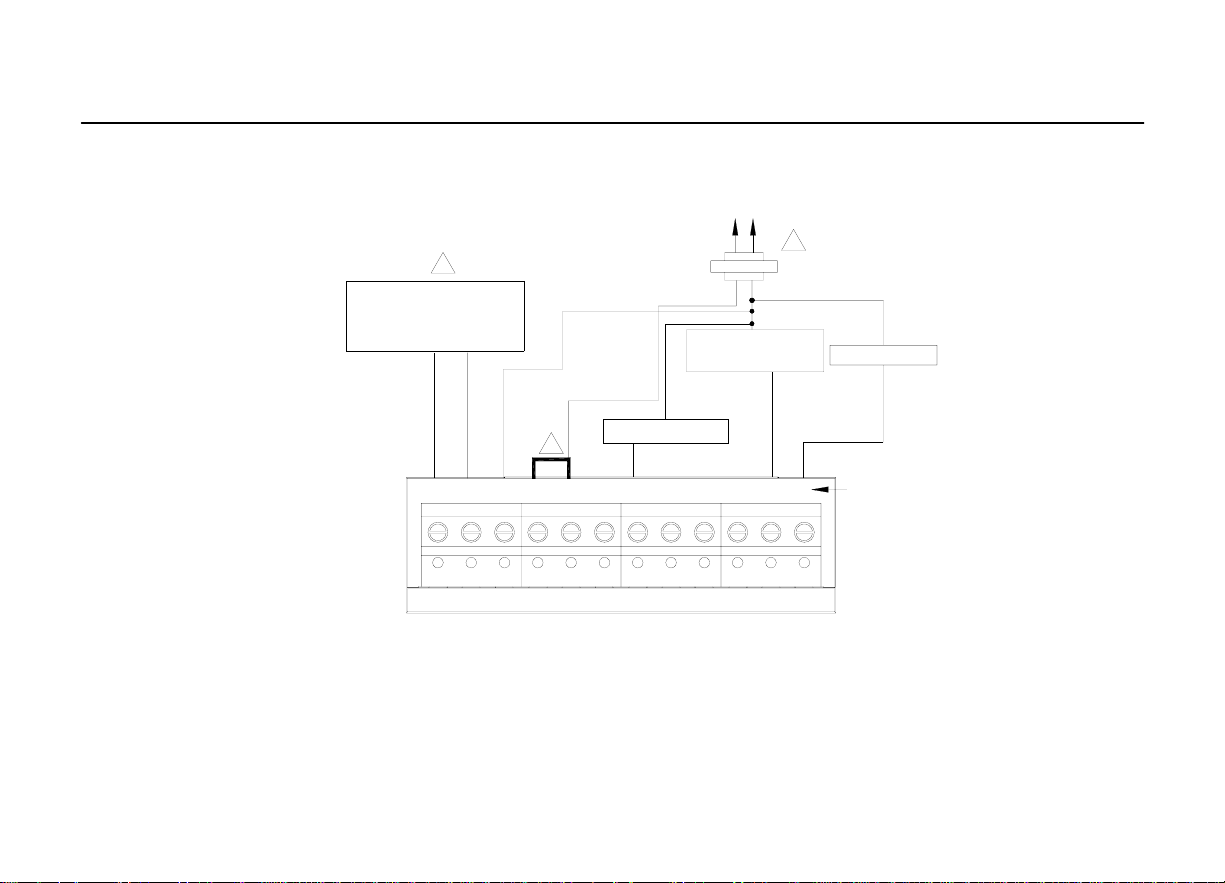
1.POWER SUPPLY. PROVIDE DISCONNECT MEANS AND OVERLOAD PROTECTION AS REQUIRED.
2.REMOVE FACTORY INSTALLED JUMPER
3.OPTIONAL OUTDOOR OR INDOOR REMOTE SENSOR. AVAILABLE ON SELECT MODELS. WIRES MUST HAVE A CABLE
SEPARATE FROM THE THERMOSTAT CABLE.
Fig. 10. T
y
pical hookup of conventional single-s
t
age heat and cool system with two
transformers (1H/1C conventional).
23
CONVENTIONAL
S1 S 2 C R RC W W2 Y2 Y G
OUTDOOR/INDOOR
TEMPERATURE
SENSOR
3
R
C
1
2
FAN RELAY
HEAT RELAY
R
C
1
COMPRESSOR
CONTACTOR
OPTIONAL
24VAC
COMMON
CONNECTION
CDT900 Series Touchscreen Pro
g
rammable T hermo
s
tat
a
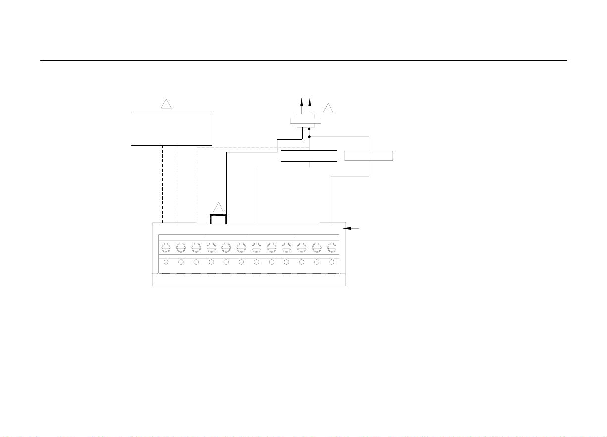
1. POWER SUPPLY. PROVIDE DISCONNECT MEANS AND OVERLOAD PROTECTION AS REQUIRED
2. FACTORY INSTALLED JUMPER.
3. OPTIONAL OUTDOOR OR INDOOR REMOTE SENSOR. AVAILABLE ON SELECT MODELS. WIRES MUST HAVE A CABLE
SEPARATE FROM THE THERMOSTAT CABLE
Fig. 11. Typical hookup of heat-only system (1 H conventional).
24
CONVENTIONAL
S1 S2 C R RC W W2 Y2 Y G
OUTDOOR/INDOOR
TEMPERATURE
SENSOR
3
HEAT RELAY
OPTIONAL
24VAC
COMMON
CONNECTION
R
C
1
2
CDT900 Series Touchscreen Pro
g
rammable T hermo
s
tat
a
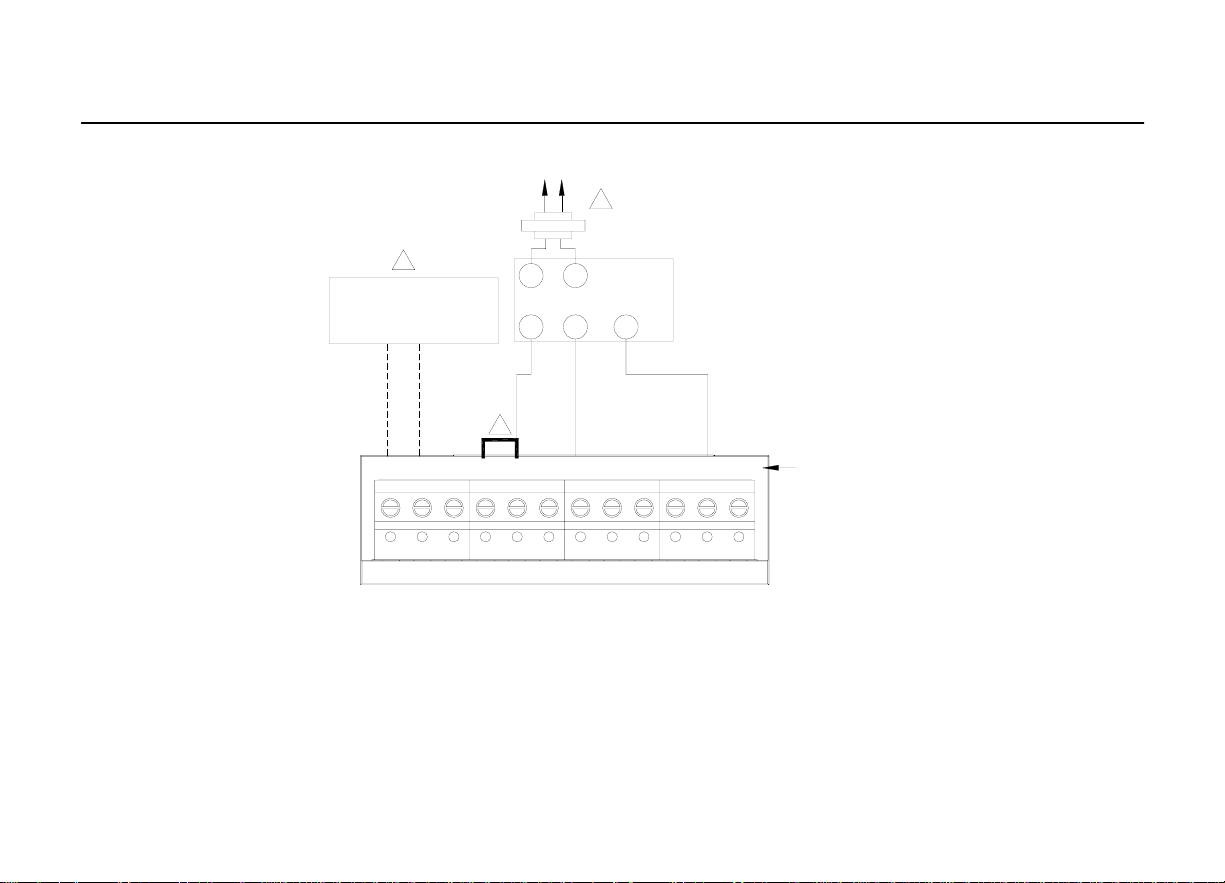
1. POWER SUPPLY. PROVIDE DISCONNECT MEANS AND OVERLOAD PROTECTION AS REQUIRED
2. FACTORY INSTALLED JUMPER.
3. OPTIONAL OUTDOOR OR INDOOR REMOTE SENSOR. AVAILABLE ON SELECT MODELS. WIRES MUST HAVE A CABLE
SEPARATE FROM THE THERMOSTAT CABLE
Fig. 12. Typical hookup of heat only system with fan (1H con ventional).
25
CONVENTIONAL
S1 S2 C R R C W W2 Y2 Y G
OUTDOOR/INDOOR
TEMPERATURE
SENSOR
3
HEAT RELAY
OPTIONAL
24VAC
COMMON
CONNECTION
R
C
1
2
FAN RELAY
CDT900 Series Touchscreen Pro
g
rammable T hermo
s
tat
a
1. POWER SUPPLY. PROVIDE DISCONNECT MEANS AND OVERLOAD PROTECTION AS REQUIRED
2. FACTORY INSTALLED JUMPER.
3. OPTIONAL OUTDOOR OR INDOOR REMOTE SENSOR. AVAILABLE ON SELECT MODELS. WIRES MUST HAVE A CABLE
SEPARATE FROM THE THERMOSTAT CABLE
Fig. 13. Typical hookup of heat only power to open and power to close zone valve
(Series 20) system.
26
OUTDOOR/INDOOR
TEMPERATURE
SENSOR
3
R
C
1
2
W
B
R
TR
TR
SERIES 20
MOTOR OR
VALVE
CONVENTIONAL
S1 S2 C R RC W W2 Y2 Y G
CDT900 Series Touchscreen Pro
g
rammable T hermo
s
tat
a
1. POWER SUPPLY. PROVIDE DISCONNECT MEANS AND OVERLOAD PROTECTION AS REQUIRED
2. FACTORY INSTALLED JUMPER.
3. OPTIONAL OUTDOOR OR INDOOR REMOTE SENSOR. AVAILABLE ON SELECT MODELS. WIRES MUST HAVE A CABLE
SEPARATE FROM THE THERMOSTAT CABLE
Fig. 14. Typical hookup of he at only system with normall y open zone valves.
27
CONVENTIONAL
S1 S 2 C R R C W W2 Y2 Y G
OUTDOOR/INDOOR
TEMPERATURE
SENSOR
3
NORMALLY OPEN
ZONE VALVE
OPTIONAL
24VAC
COMMON
CONNECTION
R
C
1
2
4
CDT900 Series Touchscreen Pro
g
rammable T hermo
s
tat
a
1. POWER SUPPLY. PROVIDE DISCONNECT MEANS AND OVERLOAD PROTECTION AS REQUIRED
2. FACTORY INSTALLED JUMPER.
3. OPTIONAL OUTDOOR OR INDOOR REMOTE SENSOR. AVAILABLE ON SELECT MODELS. WIRES MUST HAVE A CABLE
SEPARATE FROM THE THERMOSTAT CABLE
Fig. 15. Typical hookup of cool only system ( 1 C co nventional ) .
28
CONVENTIONAL
S1 S2 C R RC W W2 Y2 Y G
OUTDOOR/INDOOR
TEMPERATURE
SENSOR
3
COMPRESSOR
CONTACTOR
OPTIONAL
24VAC
COMMON
CONNECTION
R
C
1
2
FAN RELAY
HEAT RELAY

CDT900 Series Touchscreen Pro
g
rammable T hermo
s
tat
a
1. POWER SUPPLY. PROVIDE DISCONNECT MEANS AND OVERLOAD PROTECTION AS REQUIRED
2. FACTORY INSTALLED JUMPER.
3. OPTIONAL OUTDOOR OR INDOOR REMOTE SENSOR. AVAILABLE ON SELECT MODELS. WIRES MUST HAVE A CABLE
SEPARATE FROM THE THERMOSTAT CABLE
Fig. 16. Typical hookup of conventional multis
t
age two-s
t
age heating and two-s
t
ag
cooling in a single-transformer system (2H/2C, 2H/1C or 1H/2C conventional).
29
S1 S2 C R RC W W2 Y2 Y G
OUTDOOR/INDOOR
TEMPERATURE
SENSOR
3
OPTIONAL
24VAC
COMMON
CONNECTION
MUST COME
FROM THE
COOLING
TRANSFORMER
2
FAN RELAY
HEAT RELAY 2
HEAT RELAY 1
COOL RELAY 2
COOL RELAY 1
R
C
1
CONVENTIONAL
 Loading...