

Page 1
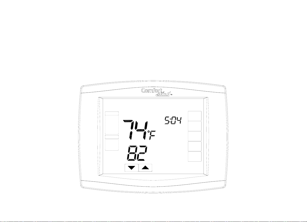
CDT900 Series Touchscreen
Programmable Thermostat
SYSTEM
COOL
FAN
AUTO
WED
Running As SCHED
Room
Set To
PM
SCHED
HOLD
CLOCK
SCREEN
MORE
Page 2

a
CDT900 Series Touchscreen Programmable Thermostat
Contents
Application/Features............................. ....... ........... ................. ................. ........................... 2
Specifications/Ordering Information ..................... ................. ................. ............................. 4
Installation ........................................................ .. ................. ...............................................13
Wiring ................................................................... ................. ................. ............................ 17
Power the Thermostat .................................. ................ ................. ..................................... 34
Installer Setup ............................. ................. ................ ...................................................... 47
Installer System Test ................. ................. ................ ........................................................ 59
`
Operation ............................. ................. ............... ............................................................... 62
Programming .................. ................. ................. .................................................................. 68
Troubleshooting ................ ................. ................. ................................................................ 97
1
Page 3

g
a
CDT900 Series Touchscreen Pro
rammable Thermostat
APPLICATION
The CDT900 Series Touchscreen Programmable Thermostat is an effortless, 7-Day
PRODUCT DATA
programmable thermostat that provides universal system compatibility, precise comfort
control and is easy-to-program.
The CDT900 Series Thermostats provide temperature control for gas, oil, electric and heat
pumps for up to 3 heat, 2 cool systems including dual fuel operation plus dehumidification
control.
2
Page 4

r
r
a
FEATURES
·Large, clear display with backlight shows the current and set temperature and
thermostat in the dark.
CDT900 Series T ouchscreen Programmable Thermostat
·Menu-driven programming make setup effortless.
·Beautiful ergonomic design is smart and sophisticated to match your custome
lifestyle.
·Touchscreen interaction
·Real-time clock keeps time during power failures and automatically updates to
daylight savings.
·"Saving Chan ges" notificat ion lets you know when the schedule ch anges have been
saved.
·Change/check reminders let you know when to service or replace filters or batteries
·Various Hold options allow you to override the program schedule, as desired.
·Armchair programming allows you to remove the thermostat from the wall fo
programming.
3
Page 5
a
SPECIFICATIONS
Thermostat Description:
Featre Description
CDT900 Series Touchscreen Programmable Thermostat
Powering methods Common wire with battery bac ku p
System types (up to3 heat/2 cool)
·Gas, oil or electric heat with air conditioning
·Warm air, hot water, high-effic iency fur naces, heat
pumps, steam and gravity
·Heat on
ly inclu
des power to open and power to
close zone val v es ( series 20) and normally-open
zone valves
·Heat only with fan
·Cool only
Changeover Manual or Auto changeover selectable
System setting Heat-Off-Cool-Auto (Emer for heat pumps)
Fan setting Auto-On-Circ
·750 mV heating systems
4
Page 6
a
Electrical Ratings:
CDT900 Series Touchscreen Programmable Thermostat
W Heating 20 - 30 Vac 02 - 1.0A
W Heating (Powerpile) 750 mV dc 100 mA dc
Y Cooling 20 - 30 Vac .02 - 1.0A
G Fan 20 - 30 Vac 02 - .60A
Terminal
Voltage (50/60 Hz ) Running Cu rrent
Temperature Setting Range:
Heating: 40°F to 90°F(4°C to 32°C).
Cooling: 50°F to 99°F (10°C to 37°C).
Operating Am bient Temperature:
32°F to 120°F(0°C to 49°C).
Shipping Temperature:
CDT900 Thermostats: -30 °F to 150 °F
(-34.4°C to 65.6°C).
5
Page 7

a
r
Operating Relative Humidity (Non-condensing):
CDT900 Series Thermostats: 5% to 90%.
CDT900 Series Touchscreen Programmable Thermostat
IRS-1: 5% to 95%.
ORS-1: 5% to 95%.
Humidity Setting Range (CDT901 models only):
Cooling: 40% to 80% RH.
Humidity Display Range (CDT901 models only):
0% to 99%.
Cycle Rates (at 50% Load):
Heating: Selectable 1 - 12 cycles per hour.
Cooling: Selectable 1 - 6 cycles per hour.
Clock Accuracy: +/- 1 minute per month.
Batteries:
Two replaceable AA alkaline batteries: Power thermostats when 24 Vac common is not used.
Non-replaceable lithium battery with ten-year life under normal use to hold calendar and time
settings. Alkaline batteries keep calendar and time after lithium battery is no longe
functional.
6
Page 8

a
Cool Indication:
CDT900 series Touchscreen Thermostats show "Cool On" on the screen when Cool is
CDT900 Series Touchscreen Programmable T hermostat
activated.
Heat Indication:
CDT900 series Touchscreen Thermostats show "
activated.
Heat On
" on the screen when Heat is
7
Page 9

a
r
ORDERING INFORMATION
If you have additional questions, need further informatio n, or would like to comment on ou
products or services, please write or phone:
CDT900 Series Touchscreen Programmable T hermostat
1. Smart Electric
Attn: Warranty Department
12201 NW 107th Ave
Miami, Fl 33178
2. Call Customer Service at 1-866-591-9898
Auxiliary Heat Indication:
CDT900 Touchscreen Thermostats show "
is activated.
Au
x Heat On" on the screen when Auxiliary H eat
Emergency Heat Indication:
CDT900 Touchscreen Thermostats show "
activated and the System mode is in the Emer position.
Calibration:
He
at On" on the screen when Emergency Heat is
CDT900 Touchscreen Thermostats are factory-calibrated and require no field calibration.
Nomenclature:
8
Page 10
a
CDT900 Series Touchscreen Programmable T hermostat
Series System Stages
CDT900
3H/2C CDT900 - Standard
CDT901
CDT901-Humidity Sensor
Application
Mounting Means:
CDT900 Series Touchscreen Thermostat: Mounts directly on the wall in the living space
using mounting screws and anchors provided.
Outdoor Sensor: Mounts outside of living space with mounting clip and screws provided.
Remote Indoor Sensor: Mounts directly on the wall using mounting screws and anchors
provided.
Dimensions:
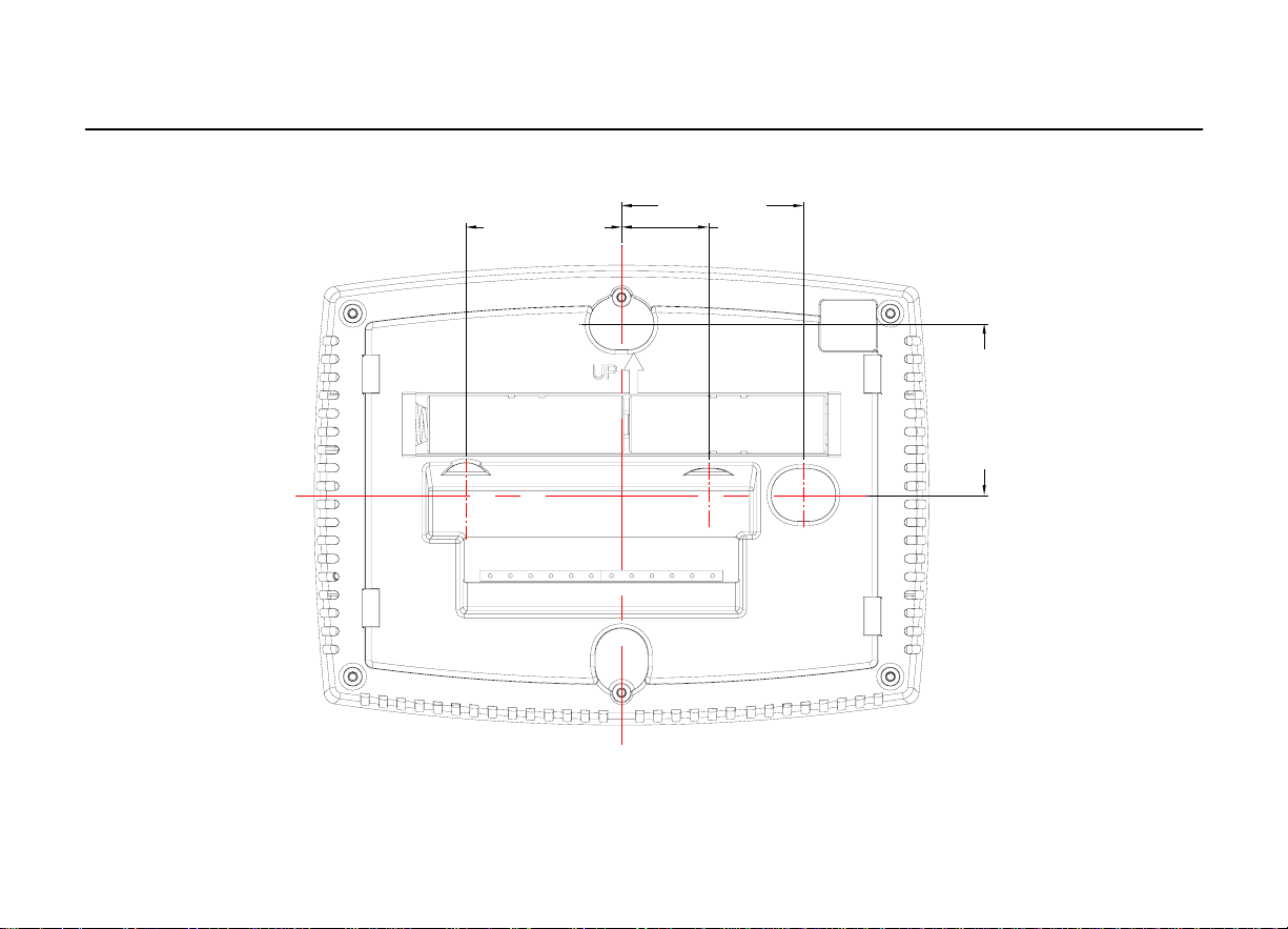
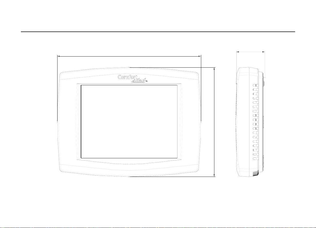
CDT900 Series Touchscreen T h er m o s t at: see Fig 1.
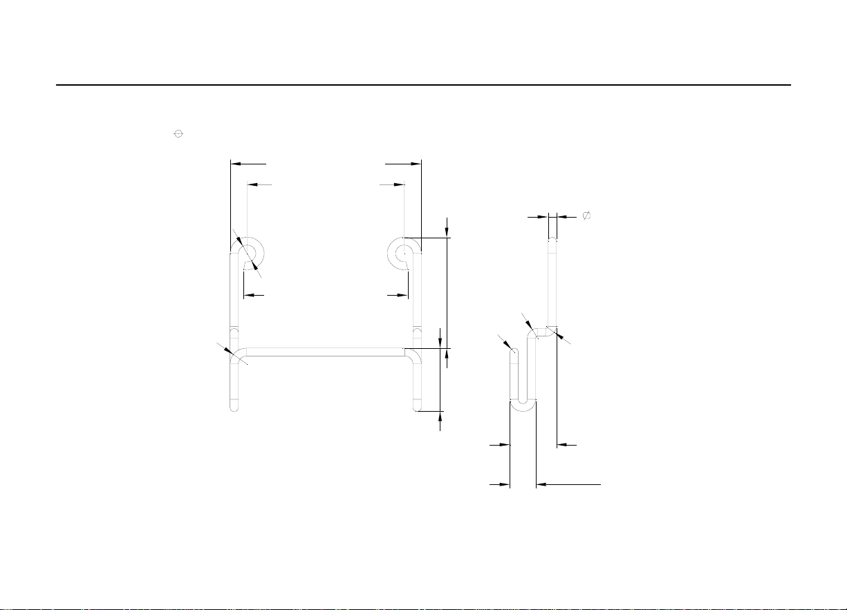
1. CDT900 Outdoor Sensor Mounti ng Clip: see Fig 2.
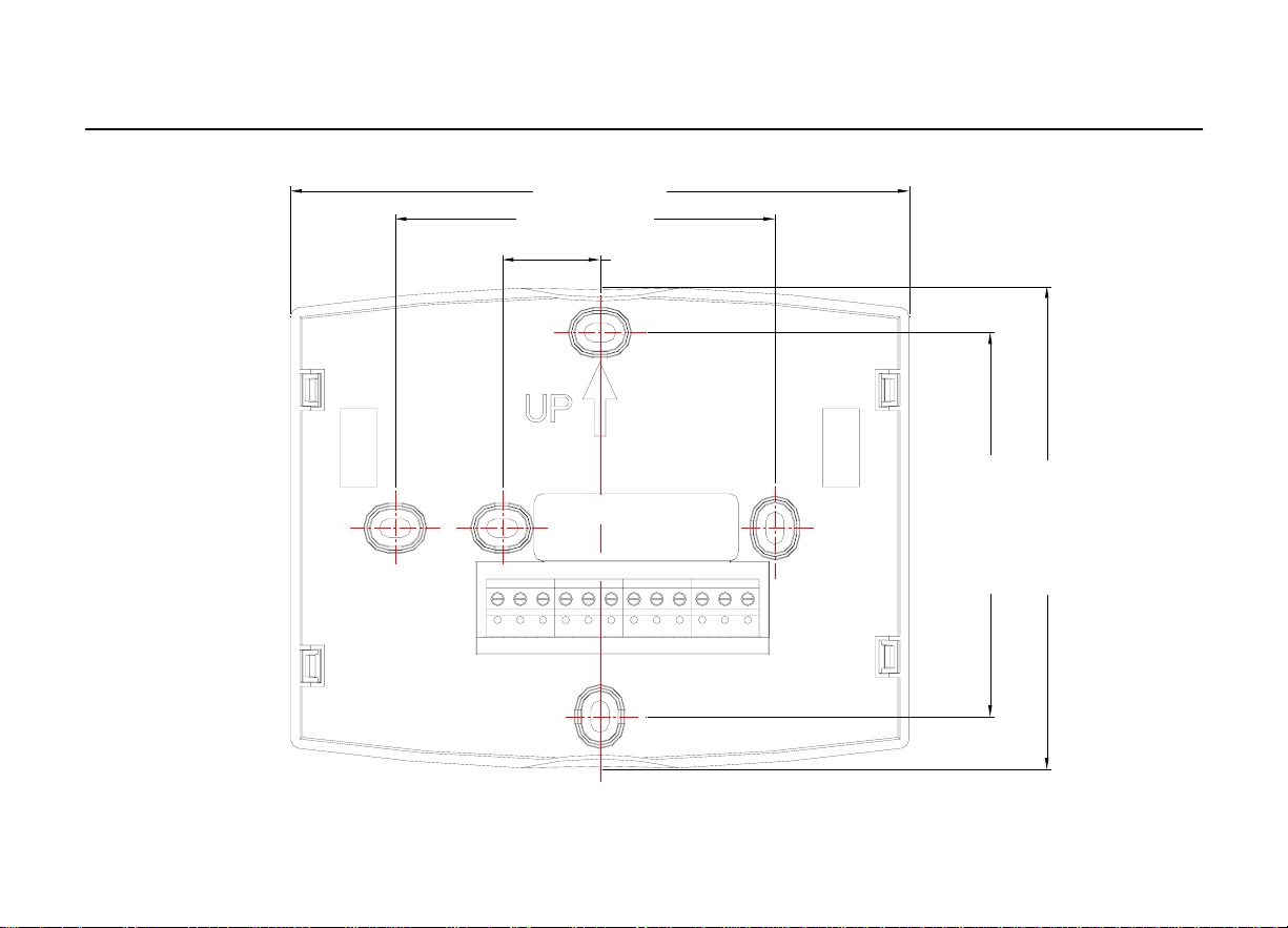
2. Cover Plate: see Fig 3.
3. CDT900 Series Remote Indoor Sensor: see Fig. 4
9
Page 11
a
CDT900 Series Touchscreen Programmable T hermostat
1.77 in.(45mm)
1.51 in.(38.5mm) 0.84 in .(21.5mm)
1.67 in.(42.5mm)
10
Page 12
a
CDT900 Series Touchscreen Programmable T hermostat
5.98 in.(152mm)
4.48in. (114mm)
1.17 in.(29.84mm)
Fig. 1. Touchscreen Thermostat dimensions in in. (mm).
11
Page 13
a
2
CDT900 Series Touchscreen Programmable T hermostat
0
R1
.
1
7
i
n
.
(
4
.
2
m
m
)
.
6
i
n
.
(
4
m
m
)
1.82 in.(46.3mm)
1.49 in.(38mm)
1.56 in .(39.7mm)
R
0
.
R
1.10 in.(28.1mm)
0
4
i
n
0
.
0
9
8
i
n
.
(
2
.
5
m
.
(
m
m
m
)
)
1
0.08 in.(2mm)
R
0
.
0
9
8
i
n
.
(
2
.
5
m
m
)
0.44 in .(11.2mm)
Fig. 2. Outdoor Sensor Mounting Clip dimensions in in. (mm).
0.62 in.(16mm)
0.24 in.(6.2mm)
1
Page 14
a
CDT900 Series Touchscreen Programmable T hermostat
5.35 in.(136mm)
3.29 in.(83.5mm)
0.85 in .(21.5mm)
3.29 in.(83.5mm)
4.13 in.(105mm)
Fig. 3. Cover Plate dimensions in in. (mm).
13
Page 15

a
r
INSTALLATION
CDT900 Series Touchscreen Programmable T hermostat
When Installing this
1.Read these instructions carefully. Failure to follow the instructions can damage the product
or cause a hazardous con dition.
2.Check the ratings given in the instructions to make sure the product is suitable for you
application.
3.Installer must be a trained, experienced ser vic e technician.
4.After completing installation, use these instructions to check out the product operation.
Selecting
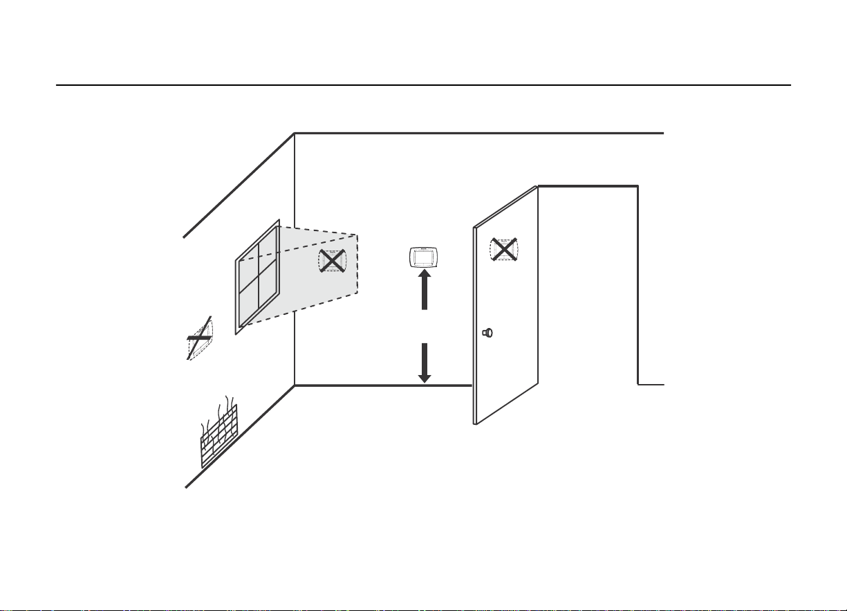
Install the thermostat about 5 ft. (1.5m) above the floor in an area with good air circulation at
average temperature. See Fig. 5.
Do not install the thermostat where it ca n be affected by:
----Drafts or dead spots behind doors and in corners.
----Hot or cold air from ducts.
----Radiant heat from sun or appliances. Concealed pipes and chimneys.
----Unheated (uncooled) areas such as an outsid e wall behind the thermostat.
Location
Product...
14
Page 16
a
CDT900 Series Touchscreen Programmable T hermostat
5FEET
1.5METERS
Fig. 5. Selecting thermostat location.
15
Page 17

a
r
Installing Wallplate
CDT900 Series Touchscreen Programmable T hermostat
CAUTION
Electrical Hazard.
Can cause electrical shock or equipment damage.
Disconnect power before wiring.
The thermostat can be mounted horizontally on the wall
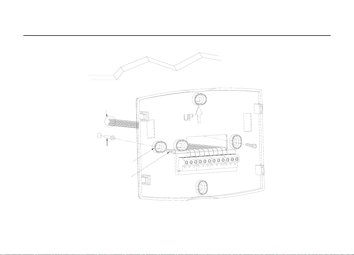
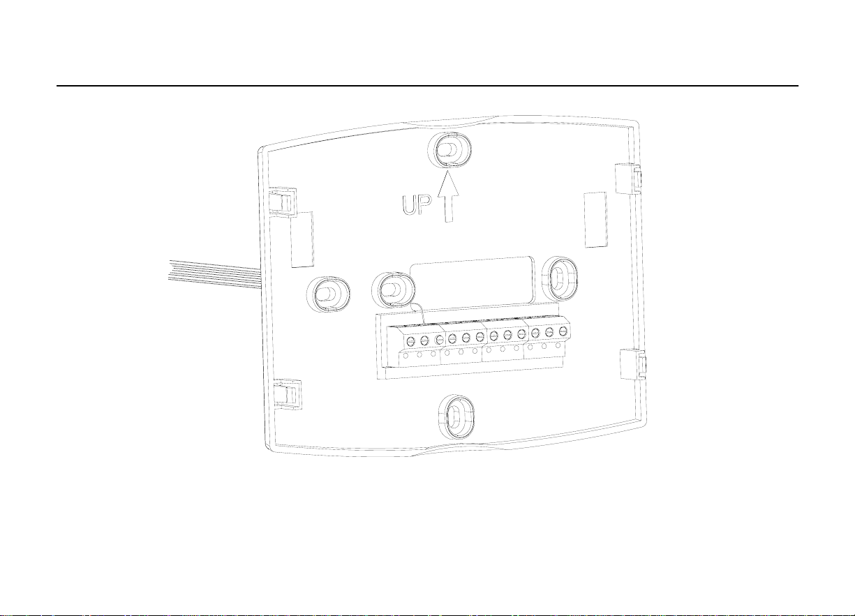
1.Position and leve l the wallplate (fo r appe arance only).
2.Use a pencil to mark the mounting holes.
3.Remove the wallplate from the wall and, if drywall, drill two holes in the wa ll, as marked. Fo
firmer material such as plaster, drill two holes. Gently tap anchors (provided) into the drilled
holes until flush with the wall.
4.Position the wallplate over the holes, pulling wires through the wiring opening. See Fig. 6
5.Insert the mounting screws into the holes and tighten.
16
Page 18
a
CDT900 Series Touchscreen Programmable T hermostat
WALL
WIRES THROUGH
WALL AND WIRE
SLOT
WALL ANCHORS
M0UNTING
HOLES(2)
M0UNTING
SCREWS(2)
Fig. 6. Mounting wallplate.
17
Page 19
a
A
r
WIRING (FIG. 9
ll wiring must comply wi th local electrical co des and ordinances.
-
21)
1.Select set of terminal identifications (Table 1) that corresponds with system type
CDT900 Series Touchscreen Programmable T hermostat
(conventional or heat pump in Fig. 7).
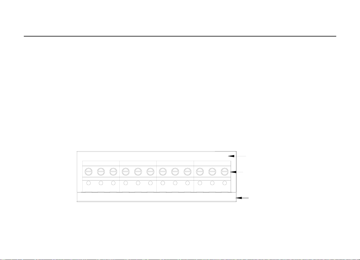
2.Loosen the screws for the appropriate system type selected; see Table 1. See T able 2 fo
terminal designation descriptions. Insert wires in the terminal block under the loosened
screw. See Fig. 8.
3.Securely tighten each screw.
4.Push excess wire back into the hole.
5.Plug the hole with nonflammable insulation to prevent drafts from affecting the thermostat.
6.See Fig. 9 through 21 for typical wiring hookups.
S1 S2 C R RC W W2 Y2 Y G
S1 S2 C R RC E L Y2 Y G
O/B AUX
CONVENTIONAL
SCREW
TERMINALS
HEAT PUMP
Fig. 7. Selecting terminal identifications for
system type.
18
Page 20
a
CDT900 Series Touchscreen Programmable T hermostat
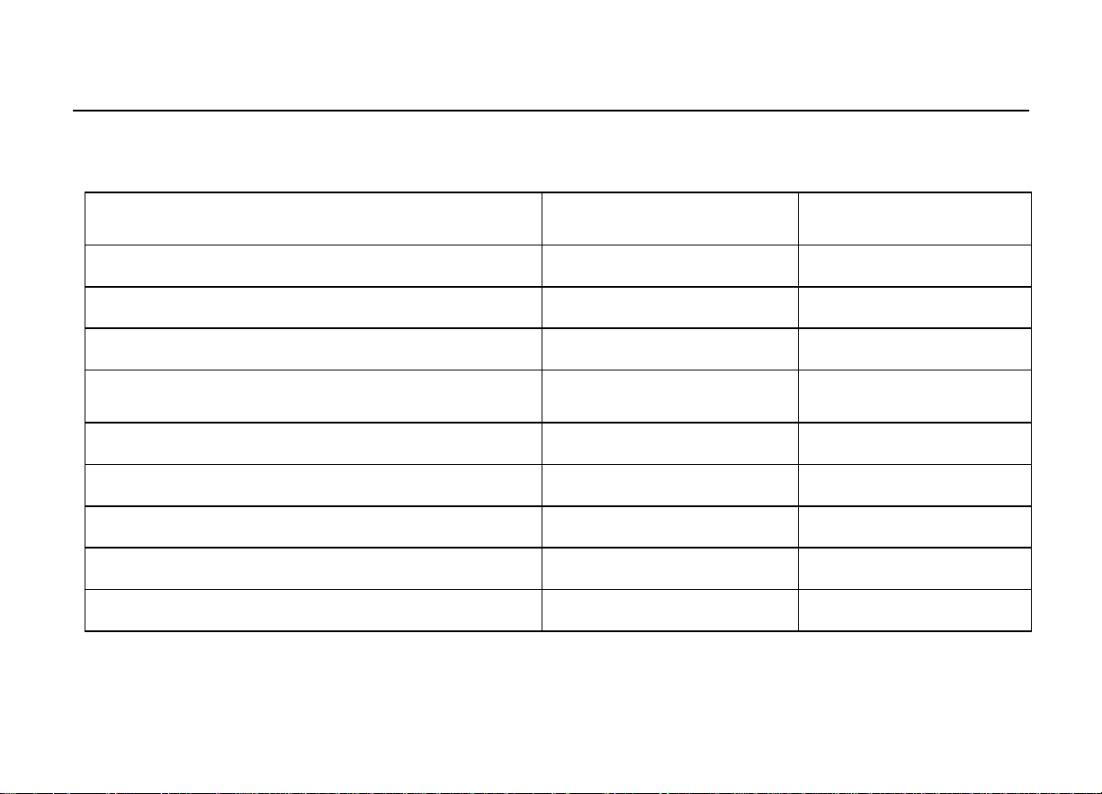
Table 1. Select ing Terminal Identifications for System Type.
Heat Only (Series 20) Power to open and
System Type
Standard Heat/Cool Conventional
Heat Only Conventional
Heat Only with Fan Conventional
power to close zone valves
Normally Open Zone Valves Heat Only
Cool Only Conventional
Wallplate Terminal
Identifications
Conventional
Conventional
Standard Multistage up to 2 Heat/2 Cool Conventional
Heat Pump with No Auxiliary Heat Heat Pump
Heat Pump with Auxiliary Heat Heat Pump
Wirin g Diagram
Reference
9, 10
11
12
13
14
15
16, 17
18, 19
20, 21
19
Page 21
a
R
TANT
CDT900 Series Touchscreen Programmable T hermostat
IMPO
Fig. 8. Inserting wires in terminal block.
:Use 18 gauge thermostat wire.
20
Page 22
a
r
A
Table 2. Terminal Designation Descriptions.
CDT900 Series Touchscreen Programmable Thermostat
Terminal Designation Description
Rc (see Note 1)
R (see Note 1)
C (see Note 2)
W Heat relay
Power for cooling--connect to secondary side of cooling
system transformer
Power for heating--connect to secondary side of heating
system transformer
Common wire from secondary side of cooling system
transformer
Y Compressor contactor
G Fan relay
Y2 Second stage cooling
W2 Second stage heat relay
O/B (see Note 3) Changeover valve for heat pump systems
AUX Auxiliary heat relay for heat pump systems
E Emergency heat relay for heat pump systems
L (see note 4) Equipment monitor for heat pump systems
S1, S2 Optional outdoor or indoor remote sensor
NOTES:.
1.When sed in a single-transformer system, leave metal jumper wire in place between Rc
and R. If used on a two-transformer system, remove metal jumper wire between Rc and R.
2.Common wire is optional when thermostat is used with batteries.
3. If thermostat is configured for a heat pump system in the Installer Setup, configure
changeover valve for cool (O -factory setting) or heat (B).
4.L terminal is an input (system monitor) when the System mo de is in the Heat, Off, Cool o
uto position. L terminal is a 24 Vac output when System mode is Emergency Heat. Must
connect the 24 Vac Common when using the L terminal. See LCD Indication section for more
details.
21
Page 23
a
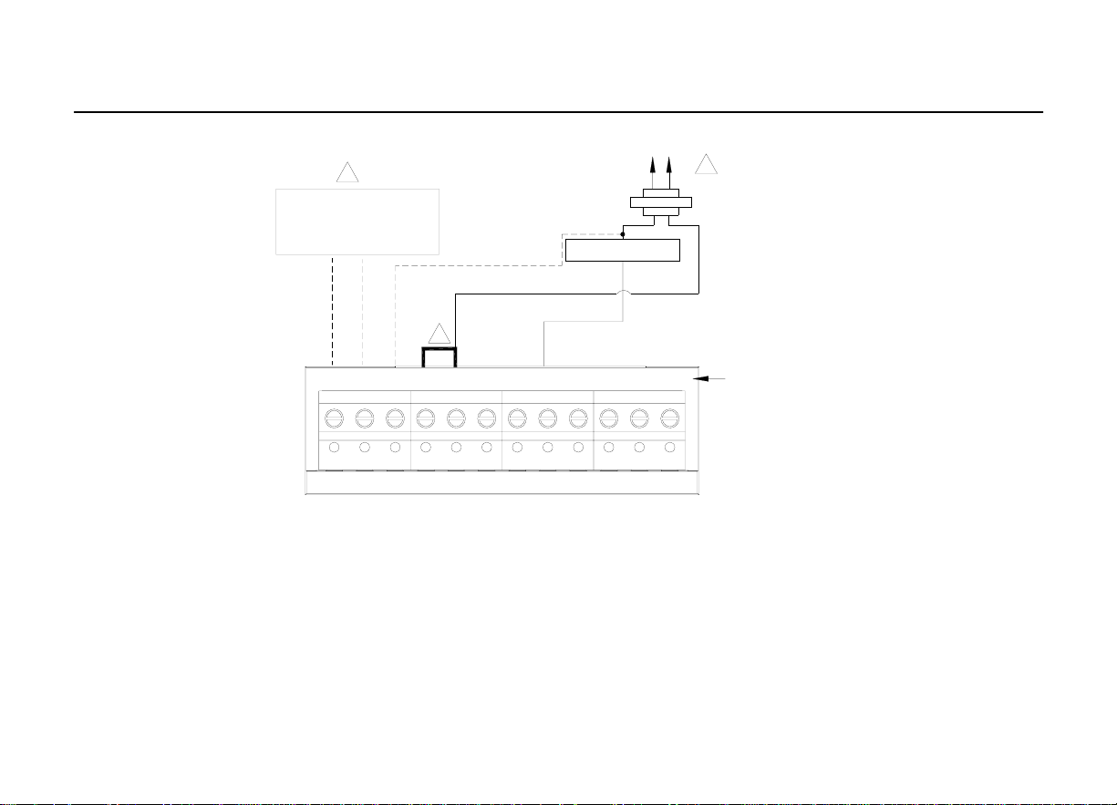
CDT900 Series Touchscreen Programmable T hermostat
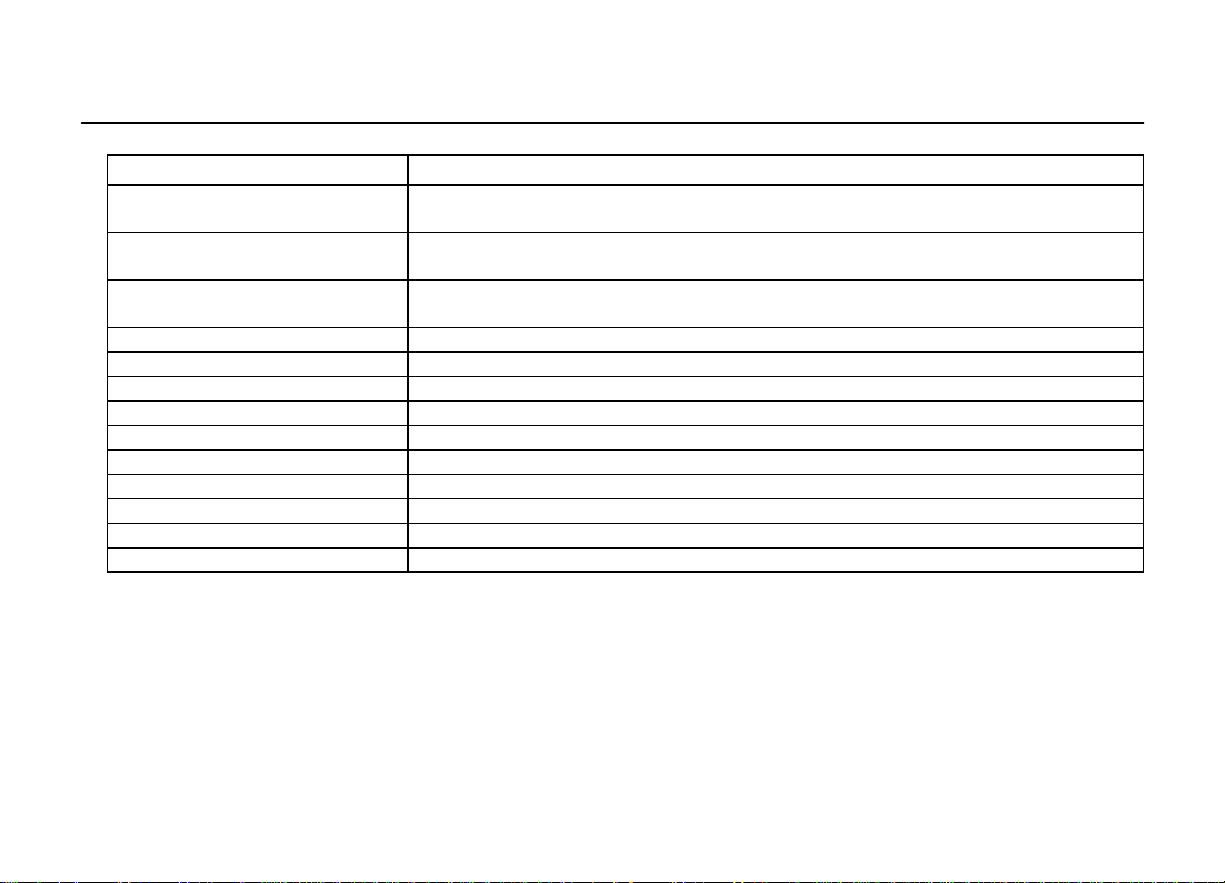
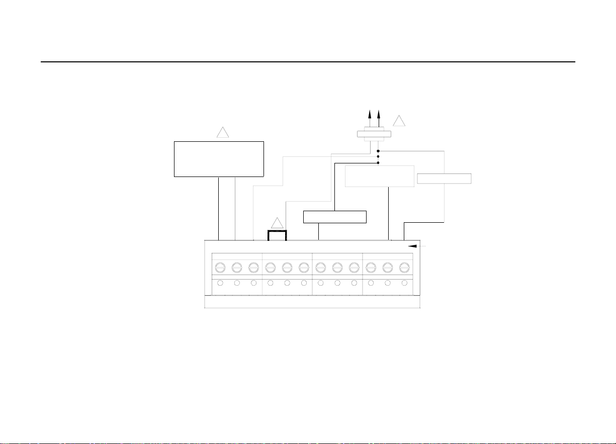
3
OUTDOOR/INDOOR
TEMPERATURE
SENSOR
OPTIONAL
24VAC
COMMON
CONNECTION
C
R
1
HEAT RELAY
FAN RELAY
S1 S2 C R RC W W2 Y2 Y G
2
CONVENTIONAL
1.POWER SUPPLY. PROVIDE DISCONNECT MEANS AND OVERLOAD PROTECTION AS REQUIRED.
2. FACTORY INSTALLED JUMPER.
3.OPTIONAL OUTDOOR OR INDOOR REMOTE SENSOR. AVAILABLE ON SELECT MODELS. WIRES MUST HAVE A CABLE
SEPARATE FROM THE THERMOSTAT CABLE
Fig. 9. Typical hookup of conventional single-stage heat and cool system with single
transformer(1H/1C conventional).
22
Page 24
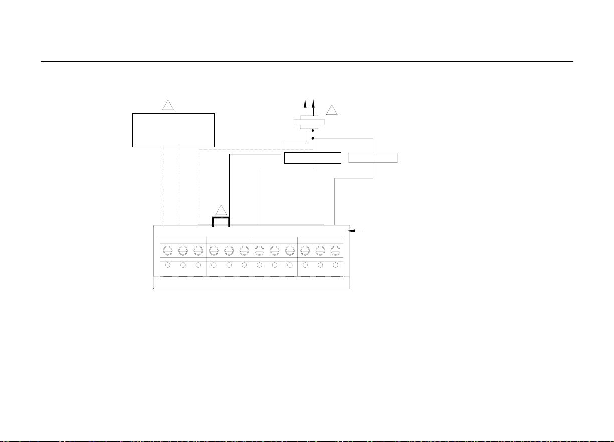
OUTDOOR/INDOOR
TEMPERATURE
SENSOR
3
HEAT RELAY
C
R
R
1
COMPRESSOR
CONTACTOR
C
1
OPTIONAL
24VAC
COMMON
CONNECTION
FAN RELAY
1.POWER SUPPLY. PROVIDE DISCONNECT MEANS AND OVERLOAD PROTECTION AS REQUIRED.
2.REMOVE FACTORY INSTALLED JUMPER
3.OPTIONAL OUTDOOR OR INDOOR REMOTE SENSOR. AVAILABLE ON SELECT MODELS. WIRES MUST HAVE A CABLE
SEPARATE FROM THE THERMOSTAT CABLE.
S1 S 2 C R RC W W2 Y2 Y G
2
CONVENTIONAL
Fig. 10. Typical hookup of conventional single-stage heat and cool system with two
transformers (1H/1C conventional).
23
Page 25
a
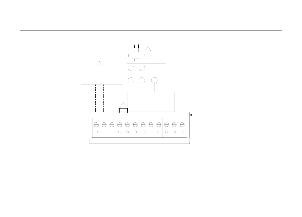
CDT900 Series Touchscreen Programmable T hermostat
3
OUTDOOR/INDOOR
TEMPERATURE
SENSOR
OPTIONAL
24VAC
COMMON
CONNECTION
2
HEAT RELAY
R
S1 S2 C R RC W W2 Y2 Y G
1. POWER SUPPLY. PROVIDE DISCONNECT MEANS AND OVERLOAD PROTECTION AS REQUIRED
2. FACTORY INSTALLED JUMPER.
3. OPTIONAL OUTDOOR OR INDOOR REMOTE SENSOR. AVAILABLE ON SELECT MODELS. WIRES MUST HAVE A CABLE
SEPARATE FROM THE THERMOSTAT CABLE
1
C
CONVENTIONAL
Fig. 11. Typical hookup of heat-only system (1 H conventional).
24
Page 26
a
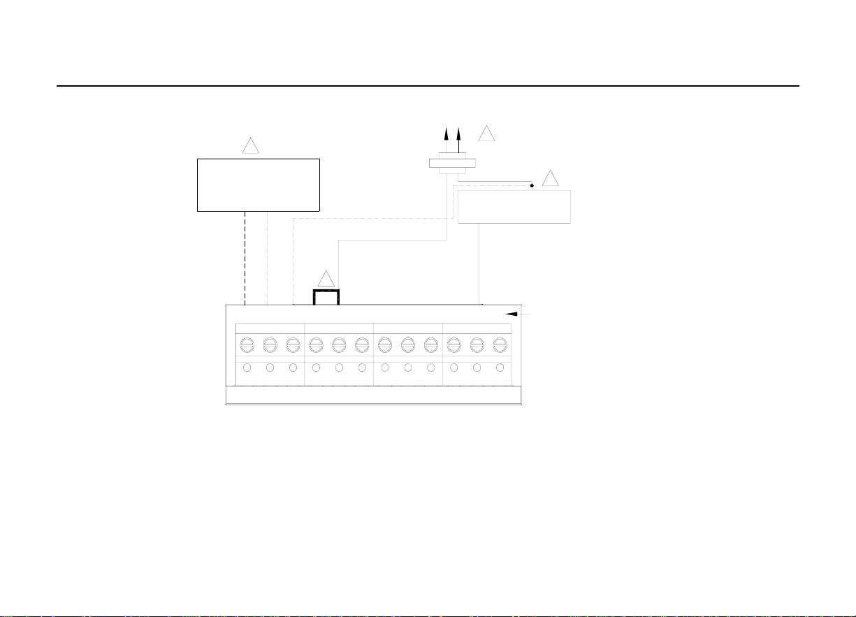
CDT900 Series Touchscreen Programmable T hermostat
1. POWER SUPPLY. PROVIDE DISCONNECT MEANS AND OVERLOAD PROTECTION AS REQUIRED
2. FACTORY INSTALLED JUMPER.
3. OPTIONAL OUTDOOR OR INDOOR REMOTE SENSOR. AVAILABLE ON SELECT MODELS. WIRES MUST HAVE A CABLE
SEPARATE FROM THE THERMOSTAT CABLE
Fig. 12. Typical hookup of heat only system with fan (1H con ventional).
OUTDOOR/INDOOR
TEMPERATURE
SENSOR
3
OPTIONAL
24VAC
COMMON
CONNECTION
2
C
R
1
HEAT RELAY
S1 S2 C R R C W W2 Y2 Y G
FAN RELAY
CONVENTIONAL
25
Page 27
a
CDT900 Series Touchscreen Programmable T hermostat
C
R
1
OUTDOOR/INDOOR
TEMPERATURE
SENSOR
3
TR
R
SERIES 20
TR
MOTOR OR
VALVE
B
W
S1 S2 C R RC W W2 Y2 Y G
2
CONVENTIONAL
1. POWER SUPPLY. PROVIDE DISCONNECT MEANS AND OVERLOAD PROTECTION AS REQUIRED
2. FACTORY INSTALLED JUMPER.
3. OPTIONAL OUTDOOR OR INDOOR REMOTE SENSOR. AVAILABLE ON SELECT MODELS. WIRES MUST HAVE A CABLE
SEPARATE FROM THE THERMOSTAT CABLE
Fig. 13. Typical hookup of heat only power to open and power to close zone valve
(Series 20) system.
26
Page 28
a
CDT900 Series Touchscreen Programmable T hermostat
1
C
OUTDOOR/INDOOR
TEMPERATURE
SENSOR
3
OPTIONAL
24VAC
COMMON
CONNECTION
R
4
NORMALLY OPEN
ZONE VALVE
1. POWER SUPPLY. PROVIDE DISCONNECT MEANS AND OVERLOAD PROTECTION AS REQUIRED
2. FACTORY INSTALLED JUMPER.
3. OPTIONAL OUTDOOR OR INDOOR REMOTE SENSOR. AVAILABLE ON SELECT MODELS. WIRES MUST HAVE A CABLE
SEPARATE FROM THE THERMOSTAT CABLE
Fig. 14. Typical hookup of he at only system with normall y open zone valves.
S1 S 2 C R R C W W2 Y2 Y G
2
CONVENTIONAL
27
Page 29
a
CDT900 Series Touchscreen Programmable T hermostat
1. POWER SUPPLY. PROVIDE DISCONNECT MEANS AND OVERLOAD PROTECTION AS REQUIRED
2. FACTORY INSTALLED JUMPER.
3. OPTIONAL OUTDOOR OR INDOOR REMOTE SENSOR. AVAILABLE ON SELECT MODELS. WIRES MUST HAVE A CABLE
SEPARATE FROM THE THERMOSTAT CABLE
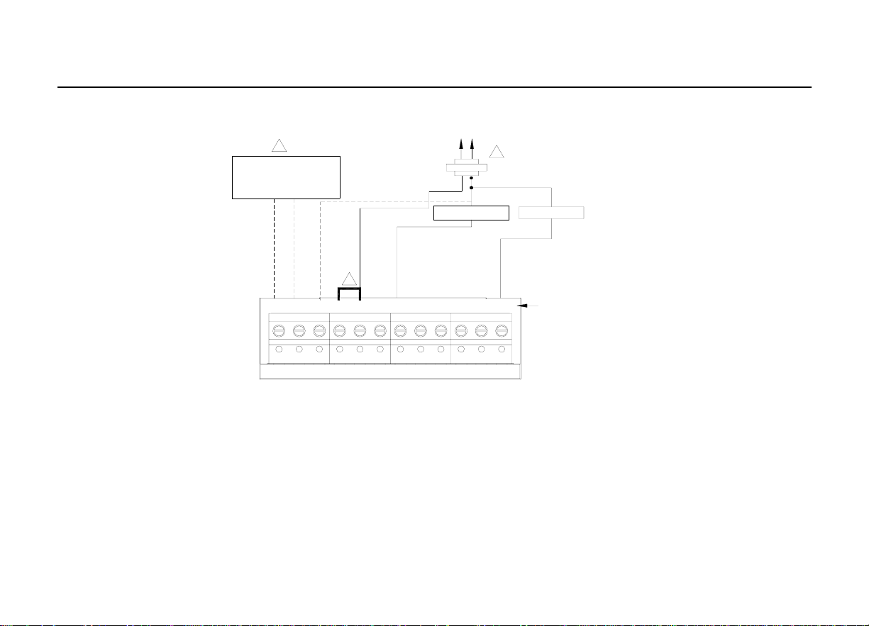
OUTDOOR/INDOOR
TEMPERATURE
SENSOR
3
S1 S2 C R RC W W2 Y2 Y G
OPTIONAL
24VAC
COMMON
CONNECTION
2
HEAT RELAY
C
R
1
COMPRESSOR
CONTACTOR
FAN RELAY
CONVENTIONAL
Fig. 15. Typical hookup of cool only system ( 1 C co nventional ) .
28
Page 30

a
CDT900 Series Touchscreen Programmable T hermostat
OUTDOOR/INDOOR
1. POWER SUPPLY. PROVIDE DISCONNECT MEANS AND OVERLOAD PROTECTION AS REQUIRED
2. FACTORY INSTALLED JUMPER.
3. OPTIONAL OUTDOOR OR INDOOR REMOTE SENSOR. AVAILABLE ON SELECT MODELS. WIRES MUST HAVE A CABLE
SEPARATE FROM THE THERMOSTAT CABLE
CONVENTIONAL
TEMPERATURE
SENSOR
3
HEAT RELAY 1
HEAT RELAY 2
2
COOL RELAY 2
COOL RELAY 1
S1 S2 C R RC W W2 Y2 Y G
C
R
1
FAN RELAY
OPTIONAL
24VAC
COMMON
CONNECTION
MUST COME
FROM THE
COOLING
TRANSFORMER
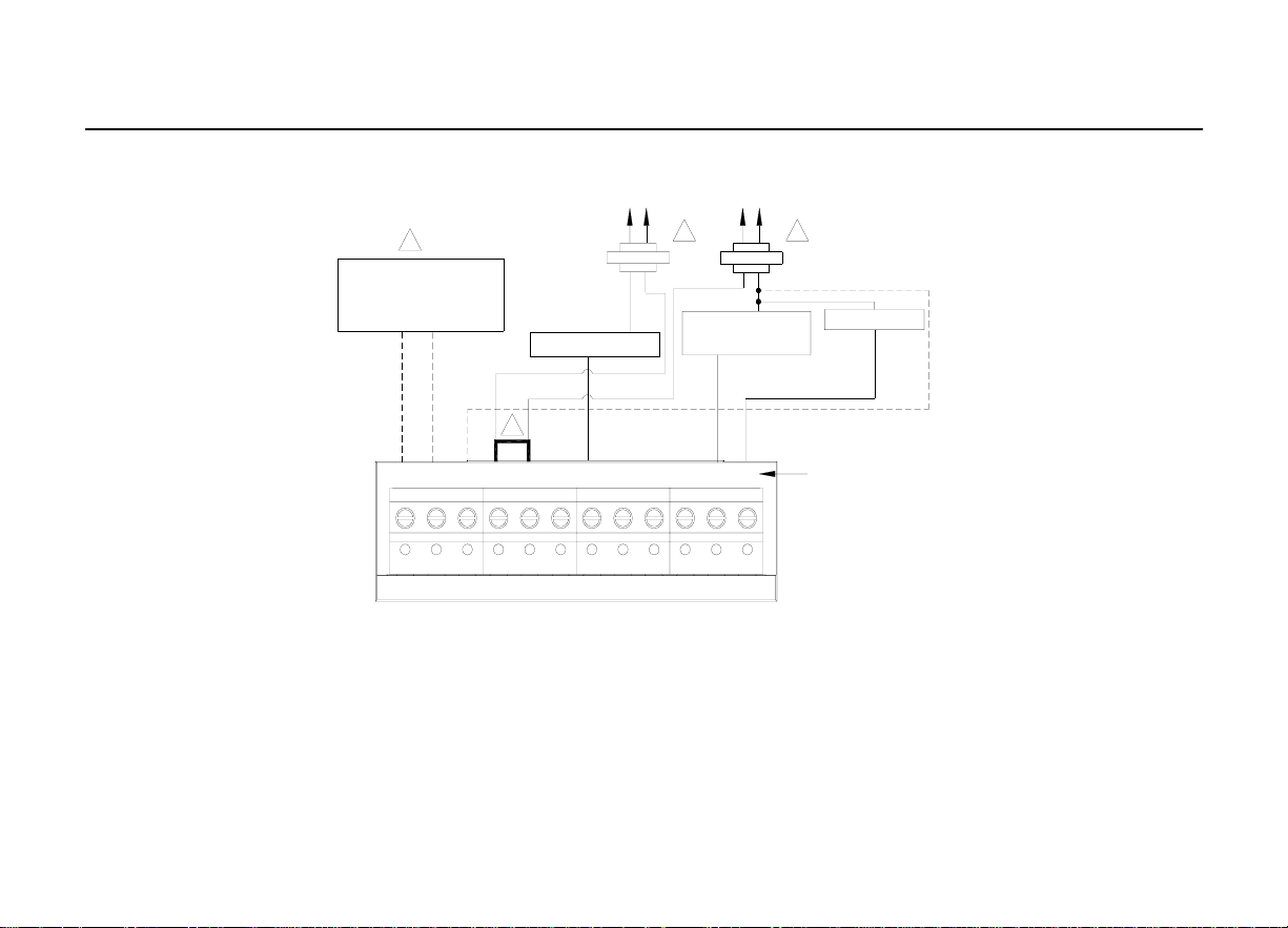
Fig. 16. Typical hookup of conventional multistage two-stage heating and two-stag
cooling in a single-transformer system (2H/2C, 2H/1C or 1H/2C conventional).
29
Page 31

a
CDT900 Series Touchscreen Programmable T hermostat
C
R
1. POWER SUPPLY. PROVIDE DISCONNECT MEANS AND OVERLOAD PROTECTION AS REQUIRED
2. FACTORY INSTALLED JUMPER.
3. OPTIONAL OUTDOOR OR INDOOR REMOTE SENSOR. AVAILABLE ON SELECT MODELS. WIRES MUST HAVE A CABLE
SEPARATE FROM THE THERMOSTAT CABLE
CONVENTIONAL
OUTDOOR/INDOOR
TEMPERATURE
SENSOR
3
HEAT RELAY 2
HEAT RELAY 1
2
S1 S2 C R RC W W2 Y2 Y G
1
COOL RELAY 2
C
R
1
COOL RELAY 1
OPTIONAL
24VAC
COMMON
CONNECTION
MUST COME
FROM THE
COOLING
TRANSFORMER
FAN RELAY
Fig. 17. Typical hookup of conventional multistage two-stage heating and two-stage
cooling in a two-transformer syst em (2H/2C, 2H/1C or1H/2C conventional).
30
Page 32

a
y
/
/
1
CDT900 Series Touchscreen Programmable T hermostat
S1 S2 C R RC W W2 Y2 Y G
1. POWER SUPPLY. PROVIDE DISCONNECT MEANS AND OVERLOAD PROTECTION AS REQUIRED
2. FACTORY INSTALLED JUMPER.
3."O/B" TERMINAL SET TO CONTROL AS EITHER "O" OR "B" IN THE INSTALLER SETUP
4.OPTIONAL OUTDOOR OR INDOOR REMOTE SENSOR. AVAILABLE ON SELECT MODELS. WIRES MUST HAVE A CABLE
SEPARATE FROM THE THERMOSTAT CABLE
HEAT PUMP
OUTDOOR/INDOOR
TEMPERATURE
SENSOR
S1 S 2 C R RC E
2
4
OPTIONAL
24VAC
COMMON
CONNECTION
Fig. 18. Typical hookup of s ingl e- stage heat pump with no auxiliar
heat pump).
O/B AUX
3
CHANGEOVER
VALVE
R
C
1
L Y2 Y G
COMPRESSOR
RELAY
FAN RELAY
backup heat (1H
31
Page 33

a
(
CDT900 Series Touchscreen Programmable T hermostat
1. POWER SUPPLY. PROVIDE DISCONNECT MEANS AND OVERLOAD PROTECTION AS REQUIRED
2. FACTORY INSTALLED JUMPER.
3.MUST CONNECT THE 24 VAC COMMON WHEN USING L. THE TERMINAL IS SHOWN AS EQUIPMENT MONITOR, CAN ALSO BE
USED AS A 24 VAC OUTPUT. SEE "HEAT PUMP LED" SECTION FOR MORE INFORMATION.
4."O/B" TERMINAL SET TO CONTROL AS EITHER "O" OR "B" IN THE INSTALLER SETUP
5.OPTIONAL OUTDOOR OR INDOOR REMOTE SENSOR. AVAILABLE ON SELECT MODELS. WIRES MUST HAVE A CABLE
SEPARATE FROM THE THERMOSTAT CABLE
HEAT PUMP
OUTDOOR/ INDOOR
TEMPERATURE
SENSOR
S 1 S 2 C R RC W W 2 Y2 Y G
S1 S2 C R RC E
5
OPTIONAL
24VAC
COMMON
CONNECTI ON
O/B AUX
2
4
CHANGEOVER
VALVE
R
L Y2 Y G
3
COMPRESSOR 2
COMPRESSOR 1
FAN RELAY
C
1
Fig. 19. Typical hookup of multistage heat pump with no auxiliary/backup heat
2H/2C heat pump).
32
Page 34

a
CDT900 Series Touchscreen Programmable T hermostat
S1 S2 C R RC W W2 Y2 Y G
HEAT PUMP
4
OUTDOOR/INDOOR
TEMPERATURE
SENSOR
S1 S2 C R RC E L Y2 Y G
3
OPTIONAL
24VAC
COMMON
CONNECTION
O/B AUX
2
CHANGEOVER
VALVE
EMERGENCY
HEAT RELAY
EQUIPMENT
MONITOR
R
C
6
1
5
HEAT 2 RELAY
(AUXILIARY HEAT)
COMPRESSOR
RELAY
FAN RELAY
1. POWER SUPPLY. PROVIDE DISCONNECT MEANS AND OVERLOAD PROTECTION AS REQUIRED
2. FACTORY INSTALLED JUMPER.
OUTDOOR SENSOR REQUIRED IN SYSTEM WITH FOSSIL FUEL BACKUP HEAT THAT IS NOT USING AN EXTERNAL FOSSIL FUEL KIT
3.
4.
OPTIONAL OUTDOOR OR INDOOR REMOTE SENSOR. AVAILABLE ON SELECT MODELS. WIRES MUST HAVE A CABLE SEPARATE FROM THE
THERMOSTAT CABLE
5.
MUST CONNECT THE 24 VAC COMMON WHEN USING L. THE TERMINAL IS SHOWN AS EQUIPMENT MONITOR, CAN ALSO BE USED AS
A 24 VAC OUTPUT. SEE "HEAT PUMP LED" SECTION FOR MORE INFORMATION.
.
"O/B" TERMINAL SET TO CONTROL AS EITHER "O" OR "B" IN THE INSTALLER SETUP.
6
Fig. 20. Typical hookup of single-stage heat pump with auxiliary/backu
heat (2H/1C heat pump).
33
Page 35

a
t
CDT900 Series Touchscreen Programmable T hermostat
S1 S2 C R RC W W2 Y2 Y G
HEAT PUMP
4
OUTDOOR/INDOOR
TEMPERATURE
SENSOR
S1 S2 C R RC E L Y2 Y G
3
OPTIONAL
24VAC
COMMON
CONNECTION
O/B AUX
2
R
6
CHANGEOVER
VALVE
EMERGENCY
HEAT RELAY
EQUIPMENT MONITOR
C
1
5
HEAT 2 RELAY
(AUXILIARY HEAT)
COMPRESSOR 1
COMPRESSOR 1
FAN RELAY
1. POWER SUPPLY. PROVIDE DISCONNECT MEANS AND OVERLOAD PROTECTION AS REQUIRED
2. FACTORY INSTALLED JUMPER.
3.
OUTDOOR SENSOR REQUIRED IN SYSTEM WITH FOSSIL FUEL BACKUP HEAT THAT IS NOT USING AN EXTERNAL FOSSIL FUEL KIT
4.
OPTIONAL OUTDOOR OR INDOOR REMOTE SENSOR. AVAILABLE ON SELECT MODELS. WIRES MUST HAVE A CABLE SEPARATE FROM THE
THERMOSTAT CABLE
MUST CONNECT THE 24 VAC COMMON WHEN USING L. THE TERMINAL IS SHOWN AS EQUIPMENT MONITOR, CAN ALSO BE USED AS
5.
A 24 VAC OUTPUT. SEE "HEAT PUMP LED" SECTION FOR MORE INFORMATION.
.
"O/B" TERMINAL SET TO CONTROL AS EITHER "O" OR "B" IN THE INSTALLER SETUP.
6
Fig. 21. Typical hookup of multistage heat pump with auxiliary/backup heat (3H/2C hea
pump).
34
Page 36

a
POWER THE THERMOSTAT
You can choose from three methods to power the thermostatBatteries
· only (AA alkaline).
· 24 Vac common wire only.
· 24 Vac common wire with battery backup (AA alkaline).
CDT900 Series Touchscreen Programmable T hermostat
Wiring 24
Vac Common
· Single-Transformer
System Conn
ect the common side of the transformer to the C screw
terminal of the thermost at wallplat e. Leave the metal jumper wire in place between Rc and
R.
·
T wo-Transformer
System C
onnect the common side of the cooling transformer to the C
screw terminal of the thermostat wa llplate. Remove the metal jumper wire between Rc and
R.
35
Page 37

a
t
t
Installing Batteries
1.Install Two AA alkaline batteries on the
back of the thermostat as marked on the
thermostat. See Fig. 22.
CDT900 Series Touchscreen Programmable T hermostat
BATTERIES(2)
2.Locate and remove the tab labeled. See
Fig. 23.
REMOVE
TAB
-+-+
Fig. 22. Ins
alling batteries .
Fig. 23. Remove
on thermostat back.
ab labeled, Remove,
36
Page 38

a
g
t
CDT900 Series Touchscreen Programmable T hermostat
Mount
1.Align the terminal screw blocks with the pins on the back of the thermostat. Push the
thermostat strai
Thermostat
ht onto the wallplate until it snaps into place. See Fig 24.
WALLPLATE
TERMINAL SCREW BLOCK
to
Wallplate
PINS ON BACK OF
THERMOSAT
Fig. 24. Mount thermos
at to wallplate.
37
Page 39

a
g
Locate and
Mount Outdoor Temperature Sensor (Optional)
Mount the sensor w here (see Fig. 25):
CDT900 Series Touchscreen Programmable T hermostat
·cannot tamper with settings.
·there is good air circulation.
·it can measure true outdoor ambient temperature.surface is flat.
·wire distance between Sensor and thermostat is less than 65.61 ft(20m).
Do not m o unt the sensor
·in direct sunlight.
·where hot or cold air blows on the sensor. Discharge line from an outdoor compressor
unit, vent or fan causes inaccurate temperature readings.
·where snow, ice or debris can cover it.
Use the following st eps to mount the sensor:
1.Remove the sensor from the mounting clip.
2.Mark the area on the location selected for mountin
the sensor mounting clip.
38
Page 40

a
CDT900 Series Touchscreen Programmable T hermostat
Fig. 25. Typical locations for ORS-1 Outdoor Sensor.
39
Page 41

a
R
T
CDT900 Series Touchscreen Programmable T hermostat
IMPO
CAUTION
Electrical Interference (Noise) Hazard.
Can cause erratic system operation.
Keep wiring at least one foot away from large inductive loads such as motors, line
starters, lighting ballasts and large power distribution panels.
Use shielded cable to reduce interference when rerouting is not possible.
ANT
Erratic temperature readings from a sensor can occur as a result of any of the
wiring practices described below. Avoid these practices to assure correct
operation. Use shielded cable to reduce interference if rerouting sensor wiring is
not possible.
40
Page 42

a
l
p
p
ply
CDT900 Series Touchscreen Programmable T hermostat
CAUTION
Electrical Shock Hazard.
Can cause electrical sho ck or equipment damage.
Disconnect
ower su
before connecting wiring.
Wiring must comply with applicable codes, ordinances and regulations:
1.Wire Outdoor Sensor to S1and S2 termin als on the thermostat. If leadwire provided is not
long enough), you need an extra cable to reach the hole at location.
a. Using color-coded, 18-gauge thermostat wire is recommended. For example of general
wiring of sensor, see Fig. 26.
b. Pigtail wiring can be used.
2.Mount Sensor in its mounting clip.
3.Plug wiring hole using nonhardening caulk or putty.
Be sure wires have a cable separate from the thermostat cable.
Do not route temperat ure sens o r w iring w ith building power wiring, next to contro
contactors or near light dimming circuits, electric motors or welding equipment.
Avoid poor wiring connections.
Avoid intermittent or missing building earth ground.
41
Page 43

a
CDT900 Series Touchscreen Programmable T hermostat
1
ORS-01
WIRING HOLE
THROUGH
2
STRUCTURE
1.USE APPROPRIATE MOUNTING MEANS FOR THE TYPE OF STRUCTURE.
2.PLUG WIRING HOLE WITH NON-HARDENING CAULK OR PUTTY .
Fig. 26. Wire Outdoor Sensor to the thermostat.
42
Page 44

a
A
f
Locate and
1.Choose a location (see Fig. 27) for mounting the sensor on an inside wall about 19.4 ft
Mount
Remote
Indoor Temperature Sensor (Optional)
(1.5m) above the floor.
CDT900 Series Touchscreen Programmable T hermostat
2.Be sure wire distance between sensor and thermostat is less than 65.61 ft(6m).
3.Make sure there is good air circulation at average temperature at the chosen location.
void the following locations because they can introduce errors in sensor
measurements. See Fig. 27.
Hot areas caused by:
(a) Concealed pipes or ducts.
(b) Drafts from fireplaces or other heat sources.
(c) Convection or radiant heat from the sun or electrical equipment.
Cold areas caused by:
(a) Concealed pipes or ducts.
(b) Drafts from windows and doors.
Unheated areas on the other side of the wall location.
Dead air areas:
(a) Behind doors, furniture and curtains. (b) In corners and alcoves.
4.Mark the area on the wall selected for mounting the Sensor or j un ction box.
5.Run wire cable t o a hole at the selected wall loc ation. Pull approximately t hree inches o
wire through the opening. Color-coded, 18-gaug e thermostat wire is recommended.
43
Page 45

y
CDT900 Series T ouchscreen Programmable Thermostat
Fig. 27. T
pical location for Indoor Sensor.
5FEET
1.5METERS
44
Page 46

a
R
T
Wire
CDT900 Series Touchscreen Programmable T hermostat
Indoor Sensor
IMPO
CAUTION
Electrical Interference (Noise) Hazard. Can cause erratic system operation.
Keep wiring at least one foot away from large inductive loads such as motors, line
starters, lighting ballastsand large power distribution panels.
ANT
Erratic temperature readings from a sensor can occur as a result of any of the
wiring practices described below. Avoid these practices to assure correct
operation.
Be sure wires have a cable separate from the thermostat cable.
Do not route temperature sensor wiring with building power wiring, next to
control contactors or near light dimming circuits, electric motors or welding
equipment.
Avoid poor wiring connections.
Avoid intermittent or missing building earth ground.
45
Page 47

a
p
p
ply
CDT900 Series Touchscreen Programmable T hermostat
Wiring must comply wi th ap p licable codes, o rdinances and regulations.
CAUTION
Electrical Shock Hazard.
Can cause electrical shock or equipment damage.
Disconnect
ower su
before connecting wiring.
1.Wire Indoor Sensor to S1 and S2 terminals on the thermostat. For an example of general
wiring of IRS-1, see Fig. 28 to wire one sensor and 29 to wire multiple sensors.
2.Push excess wi re b ac k in to the h ole . Plu g the hol e
using nonhardening caulk, putty or insulation to pr event drafts from affecting performance.
3.Remove IRS-1 sensor cover.
4.Mount IRS-1 to the wall or junction box using the screws and anchors provided.
5.Level the IRS-1 for appearance only. Device functions correctly even when not level.
6.Install IRS-1 cover.
46
Page 48

a
T
CDT900 Series Touchscreen Programmable T hermostat
C7189
C
R
2
3
1
S1 S2 C R RC W W2 Y2 Y G
1. POWER SUPPLY. PROVIDE DISCONNECT MEANS AND
OVERLOAD PROTECT ION AS REQUI RED .
2. IF MORE THAN ONE REMOTE SENSOR IS REQUIRED, REFER TO
FIGURE 3
3.. WIRES MUST HAVE A CABLE SEPARATE FROM THE THERMOSTA
CABLE.
Fig. 28. Wiring a single Indoor Sensor.
C7189 C7189
2
S1 S2 C R RC
S1 S2 C R RC
1.SENSORS MUST BE ARRANGED IN THIS CONFIGURATION TO OPERATE
CORRECTLY.
2.WIRES MUST HAVE A CABLE SEPARATE FROM THERMOSTAT CABLE
C7189 C7189
C7189 C7189 C7189
2
C7189 C7189 C7189
C7189 C7189 C7189
Fig. 29. Wiring Multiple Sensors.
1
1
47
Page 49

a
r
r
INSTALLER SETUP
Follow these steps to enter the Installe
Setup:
1.Press and release the System Key.
CDT900 Series Touchscreen Programmable T hermostat
2.Press and hold the two blank keys on
either side of the center blank key fo
approximately five seconds until screen
changes.
TUE
SYSTEM
AUTO
FAN
AUTO
Running As SCHED
Room
Set To
TUE
SCHED
AM
HOLD
CLOCK
SCREEN
MORE
SYSTEM
HEAT
OFF
COOL
CANCEL
Room
Set To
AM
DONEDONE
48
Page 50

a
r
p
CDT900 Series Touchscreen Programmable Thermostat
3.Release the two blank keys when the
screen on the thermostat matches the
screen below.
DONE
4.See screen below to review how the
thermostat keys are used during Installe
Setup. See Tables 3-5 for the Installer
Setu
Numbers and Settings.
ADVANCE TO NEXT
CHANGE THE
CURRENT SETTING
CURRENT
SETTING
INSTALLER SETUP
INSTALLER
SETUP
NUMBER
PRESS TO EXIT
INSTALLER SETUP
DONE
5.Press the Done key to exit the Installer Setup screen.
49
Page 51

a
Installer Setup
Number
0120
0130
0140 Date (Month)
0150 Date (Day)
0160 Schedule Options
0170 System Type Selection
Installer Setup
Name
Date
(Year Upper)
Date
(Year Lower)
CDT900 Series Touchscreen Programmable T hermostat
Table 3.installer Setup Menu.
Settings Notes
Select first two digits of current calendar year
(2005, etc)
Select last two digits of cu rr ent calen dar y ear
(05 for year 2005, etc)
Select number that represents current
calendar month
Select number that represents current
calendar date
0-nonprogrammable
4-7-day programmable
1-1 heat/1 cool conventional (factory setting)
2-single-stage heat pump (no auxiliary heat)
3-heat only conventional (no fan) Also for
750mV.
4-heat only conventional (with fan)
5-heat only (power to open and power to
close zone valves or normally-open zone
valves)
6-cool only conventional
7-2 heat/1 cool heat pump (with auxiliary
heat)
8-2 heat/2 cool multistage conventiona l
9-2 heat/1 cool multistage conventiona l
10-1 heat/2 cool multistage conventional
11-2 heat/2cool heat pump (no auxiliary heat)
12-3 heat/2cool heat pump (with auxiliary
heat)
it cannt be changed
2001 - 2099 available
when it is changed, the sched
need to be reprogrammed)
Available options and defaults
vary by thermostat. System
selection automatically
modifies some default settings
and/or hides other Installer
Setup options.
50
Page 52

a
Table 3.installer Setup Menu .(CONT INUES)
CDT900 Series Touchscreen Programmable T hermostat
Installer
Setup
Number
0180 Fan Control in Heating
0190
0200
0210
0220
0230
Installer Setup
Name
Changeover Valve O/B
Terminal Energized in
Heating or Cooling
(Heat Pumps Only)
Backup Heat Source
(Auxiliary Heat)
External Fuel
FossilFuel Kit
Cycles per hour (cph)
for 1st Stage
Compressor
Cycles per hour (cph)
for 2nd Stage
Compressor
Settings Notes
0-gas or oil furnace equipment controls fan in
heating (factory setting)
1-electric furnace thermostat controls fan in
heating
0-changeover valve O/B terminal setting
1-changeover valve O/B terminal is
energized in heating
0-heat pump backup heat source is electric
(factory setting)
1-heat pump backup heat source is fossil fuel
0-no external fossil fuel kit is controlling heat
pump backup heat. This thermostat controls
the dual fuel. Must install outdoor sensor and
set Installer Setup Number 0340 to number
2. 1-external fossil fuel kit is controlling heat
pump backup heat
3-cph recommended for compressors
(factory setting)
1, 2, 4, 5, 6-other cycle rate settings
3-cph recommended for compressors
(factory setting)
1, 2, 4, 5, 6other cycle rate settings
Only shown if conventional
system is selected. If heat
pump is chosen, fan defaults
to electric.
Only shown if heat pump
system is chosen.
Only shown if 2 heat/1 co ol or
3 heat/2 cool heat pump is
chosen
Only shown if fossil fuel is
chosen as backup heat
source.
Only shown if two stages of
cool are selected.
51
Page 53

a
CDT900 Series Touchscreen Programmable T hermostat
Installer Setup
Number
0240
0250
0260
Table 3.installer Setup Menu. (CONTINUES)
Installer Setup
Name
Cycles per hour (cph)
for 1st Stage
Conventional Heat
Cycles per hour (cph)
for 2nd Stage Heat
(Aux Heat for 2H/1C
Heat Pumps)
Cycles per hour (cph)
for 3rd Stage Heat Aux
Heat for 3H/2C Heat
Pumps)
Settings Notes
1- 1 cph used for steam and gravity
3-3 cph used for hot water system a n d hi g h
efficiency (90% or better) furnaces
5-5 cph used for standard fossil fuel forced
air (less than
80% efficient) systems (factory setting)
9-9 cph used for electric furnaces
2, 4, 6, 7, 8, 10, 11, 12other cycle rate
settings
1-1 cph used for steam and gravity
3-3 cph for hot water systems and high
efficiency (90% or better) furnaces
5-5 cph for standard fossil fuel forced air
(less than 90% efficient) systems (factory
setting)
9-9 cph used for electric furnaces or electric
auxiliary heat for heat pump systems
2, 4, 6, 7, 8, 10, 11, 12-other cycle rate
settings
Not shown if system selection
is heat pump. Selection in this
stage changes default cph for
2nd stage heat.
Only shown if two stages of
heat are selected.
Only shown if 3H/2C heat
pump is selected.
52
Page 54

a
Installer Setup
Number
0270
0280 Continuous Backlight
0300 Changeover
0310 Deadband
0320
Table 3.installer Setup Menu. (CONTINUES)
Installer Setup
Name
Cycles per hour (cph)
for Emer
Temperature Indication
Scale
CDT900 Series Touchscreen Programmable T hermostat
Settings Notes
3-3 cph for hot water systems and high
efficiency (90% or better) furnaces
5-5 cph for standard fossil fuel forced air
(less than 90% efficient or better) systems
9-9 cph for electric strip heat for heat pumps
0-Backlight function disable
1-Backlight function enable
0-manual changeover (factory setting)
1-auto changeover
Heating and cooling setpoints can be set no
closer than chosen value:
2-2°F (1.5°C)
3-3°F (2°C)
4-4°F (2.5°C)
5-5°F (3°C)
6-6°F (3.5°C)
7-7°F (4°C)
8-8°F (4.5°C)
9-9°F (5°C)
0-fahrenheit temperature display (facto ry
setting)
1-celsius temperature display
Only shown if 2H/1C or 3H/2C
heat pump is selected.
.
Shown only if automatic
changeover is selected.
when it is changed, the sched
need to be reprogrammed)
53
Page 55

a
Installer Setup
Number
0330 Daylight Savings
0340
0350
Table 3.installer Setup Menu. (CONTINUES)
Installer Setup
Name
Remote Temperature
Sensor (Outdoor or
Indoor)
Heat Pump
Compressor Lockout
or (Balance Point)
CDT900 Series Touchscreen Programmable T hermostat
Settings Notes
1-daylight savings is on (factory setting).
0-daylight savings is off.
0-no remote temperature sensor
1-outdoor temperature sensor for display
only.
2-outdoor temperature sensor for
control.Outdoor sensor used for Heat Pump
Lockout settings. (See Heat Pump
Temperature Lockout section for more
details.)
3-indoor temperature sensor
0-no compressor lockout.
15°F (-9.5°C)
20°F (-6.5°C)
25°F (-4°C)
30°F (-1°C)
35°F (1.5°C)
40°F (4.5°C)
45°F (7°C)
Set to 0 in areas that do not
follow daylight savings.
Defaults and Options depend
on System Type selection.
Indoor Temperature Sensor
uses an averaging network
and does not include on-board
sensor.
Default depends on other
selections. Shown if control is
selected. (See section for
more information.)
54
Page 56

a
CDT900 Series Touchscreen Programmable T hermostat
Installer Setup
Number
0360
0380
0500
Table 3.installer Setup Menu. (CONTINUES)
Installer Setup
Name
Heat Pump Auxiliary
Lockout
Indoor
Dehumidification
Control
Furnace Change
Reminder
Settings Notes
0-no auxiliary heat lockout.
40°F (4.5°C)
45°F (7°C)
50°F (10°C)
55°F (13°C)
60°F (15.5°C)
0-No indoor dehumidification control.
1-Dehumidification control activated.
0-furnace filter reminder off
1-10 run time days
2-30 run time days
3-60 run time days
4-90 run time days
5-120 run time days
6-365 run time days
Shown if electric is chosen fo r
backup heat source and
outdoor temperature sensor
for control is selected. (See
Advanced Features section for
more information.)
Available on select odels. If
dehumidification control is
activated and autochangeover is selected in
Installer Setup Number 0300,
the deadband minimum is
defaulted to 5°F (3°C) in
Number 0310.
Run time based on call for fan.
55
Page 57

a
CDT900 Series Touchscreen Programmable T hermostat
Installer Setup
Number
Table 3.installer Setup Menu. (CONTINUES)
Installer Setup
Name
Humidifier Pad
0510
0520
0530
0540 Number of Periods
0580
0600
0610
0640 Clock Format
Replacement
Reminder
UV Lamp Replacement
Reminder
Adaptive Intelligent
Recovery
Minimum Compressor
Off Time
Heat Temperature
Range Stop
Cool Temperature
Range Stop
0-humidifier pad replacement reminder off
1-90 calendar days
2-180 calendar days
3-365 calendar days
0-UV lamp replacement reminder off
1-365 calendar days
1-Adaptive Intelligent Recovery control is
activated (system starts early so setpoint is
reached by start of program period).
0-Conventional Recovery (system starts
recovery at programmed time)
2-two periods available (Wake and Sleep)
4-four periods available (Wake, Leave,
Return and Sleep)
5-five-minute compressor off-time setting
(factory setting)
0, 2, 3, 4-other compressor off-time settings
40-90-temperature range (1 °F increme nt s) o f
heating setpoint.
50-99-temperature range (1 °F increme nt s) o f
cooling setpoint.
12-12 hour clock (factory setting)
24-24 hour clock
Settings Notes
Not shown if nonprogrammable isselected. 2 or
4 applies to all days of the
week. (when it is changed, the
sched need to be
reprogrammed)
Shown in 1/2 °C.
Shown in 1/2 °C.
56
Page 58

a
CDT900 Series Touchscreen Programmable T hermostat
Installer Setup
Number
0650
0660
0670 Keypad Lockout
0680
Table 3.installer Setup Menu. (CONTINUES)
Installer Setup
Name
Extended Fan OnTime
Heat
Extended Fan On Time
Cool
Temperature Control in
Heat
Settings Notes
0-no extended fan operation after call for
heat ends
90- fan operation is extended 90 seconds
after call for heat ends.
0.no extended fan operation after call for cool
ends
90.fan operation is extended 90 seconds
after call for cool ends.
0-unlocked keypad
1-partially locked keypad
2-fully locked keypad
1-less aggressive temperature control (could
cause temperature undershoot)
2-Standard temperature control in heating
(factory setting)
3-more aggressive temperature control
(could cause temperature overshoot)
Not shown if fan operation is
set to fossil fuel or in Cool Only
Systems
Not shown in Heat Only
Systems.
Unlockedóall functions are
available.Partially locked only
temperature up and down
keys and ability to enter and
modify Installer Setup mode
are available.
Fully locked only ability to
enter and modifyInstaller
Setup mode are available .
Applies to recovery ramp and
use of auxiliary heat during
recovery.
Choose 1 if getting
temperature overshoot.
Choose 3 if getting
temperature undershoot.
57
Page 59

a
CDT900 Series Touchscreen Programmable T hermostat
Installer Setup
Number
0690
0700
0710 Reset Thermostat
Table 3.installer Setup Menu. (CONTINUES)
Installer Setup
Name
Temperature Control in
Cool
Temperature Display
Offset
Settings Notes
1-less aggressive temperature control (could
cause temperature undershoot)
2-Standard temperature control in cooling
(factory setting)
3-more aggressive temperature control
(could cause temperature overshoot)
-3°F (-1.5°C)
-2°F (-1°C)
-1°F (-.5°C)
0°F (0. °C) (no difference in displayed
temperature and actual room temperature )
1°F (.5°C)
2°F (1°C
3°F (1.5°C)
0-no thermostat reset.
1-resets all Installer Setup Opt ions to default
values and resets schedule to default setting.
Applies to recovery ramp.
Choose 1 if getting
temperature overshoot.
Choose 3 if getting
temperature undershoot.
Only calendar settings and
time are retained.
58
Page 60

a
INSTALLER SYSTEM TEST
Use the Installer System Test to test the W1 W2 E AUX Y1 Y2 and L .
CDT900 Series Touchscreen Programmable T hermostat
How
The Installer Test is part of the Installer Setup Menu.
1.Enter the Installer System Test by entering the Installer Setup.
2.Note that the test appears at the end of the Installer Setup Numbers.
3.See Fig. 30 to review how the thermost at buttons are used during the Installer System Test.
See Table 6 for available Installer Syst em Tests.
CAUTION
Equipment Damage Hazard.
Minimum compressor off time is bypassed during
Installer System Test
Avoid cycling compressor quickly.
to
Use
the
Installer System Test
59
Page 61

a
t
E
CDT900 Series Touchscreen Programmable T hermostat
SYSTEM STAUS
NUMBER
SYSTEM TEST
NUMBER
UP ARROW KEY
ADVANCES TO
NEXT SYSTEM
TEST NUMBER
DONE
ARROW ARROW
TURNS THE
SYSTER OFF
UP ARROW
TURNS THE
SYSTER ON
DONE KEY
EXITS INSTALL
SYSTEM TEST
Fig. 30. Review thermos
at buttons used during Installer System Test.
60
Page 62

a
Installer System Tests
System Test Number Test Type
Test 1 Cooling System Test
CDT900 Series Touchscreen Programmable T hermostat
Table 4. Installer System Test.
System Status Number and
Description
1-Cool stage 1 and stage 2 turn on.
0-Cool is off.
Press the Next button to go to the beginning of the Installer Setup or press the Done button to exit the Installer
System Test.
Test 2 Fan System Test
Test 3 Heating System Test
Test 4 Emergency Heat Test
1-Fan turns on.
0-Fan turns off.
1-Heat stage 1 and stage 2 (aux
heat) turn on.
0-Heat is off.
1-Emergency heat and L turn on.
0-Emergency heat and L turns off.
61
Page 63

a
OPERATION
CDT900 Series Touchscreen Programmable T hermostat
Thermostat Keys
SYSTEM
SELECTS EM.
HEAT/OFF/COOL
AUTO/EMER
TUE
SYSTEM
HEAT
FAN
AUTO
CLOCK
SETS THE TIME
FORWARD
OR BACK
Running As SCHED
Room
Set To
FAN
SELECTS
ON/AUTO/CIRC
DOWN ARROE
LOWERS
TEMPERATURE
SETTING
UP ARROW
RAISES
TEMPERATURE
SETTING
HOLD
SETS A PERMANENT
HOLD AND ACTIVITIES
VACATION HOLD
AM
SCREEN
LOCKS OUT THE
SCREEN TO ALLOW
FOR CLEANING
SCHED
ENTERS
SCHEDULING
MODE
SCHED
HOLD
CLOCK
SCREEN
MORE
MORE
SHOWS ADDITION AL
ACCESSORY AND
MAINTENANCE
OPTIONS
Thermostat Display
SYSTEM
SHOWS
CURRENT
SYSTEM
POSITION
TUE
SYSTEM
HEAT
FAN
AUTO
FAN
SHOWS FAN
SETTING
TUE
SHOWS
CURRENT
DAY OF THE
WEEK
Room
Set To
SET TO
TEMPERATURE
SHOWS THE
CURRENT SET
TEMPERATURE
RUNNING AS SCHED
SHOWS THE
THERMOSTAT IS
FOLLOWING THE
PROGRAMMED
SCHEDULE
Running As SCHED Running As SCHED
INSIDE TEMPERATURE
SHOWS THE CURRENT
INSIDE TEMPERATURE
TIME
DISPLAY CURRENT
TIME OF DAY. HOLD
TIME REMAINING OR
NUMBER OF VACATION
DAYS REMAINING
SCHED
AM
HOLD
CLOCK
SCREEN
MORE
62
Page 64

a
System and Fan
Settings
System
The System key selections vary based on your heating and/or cooling system type.
Heat Thermostat controls the heating system.
Off Both heating and cooling systems are off.
Cool Thermostat controls the cooling system.
Auto Thermostat automatically changes between heating and cooling operation,
depending on indoor temperature.
Emer Emergency heat cycles to maintain temperatur e. Compressor is locked out (used
only for 2H/1C or 3H/2C heat pump systems) and auxiliary heat turn s on a s second stage if
needed.
Fan
The Fan key selections v a r y based on the heating and/or cooling system type.
On Fan runs continuously. Use this setting for improved air circulation or for more efficient
central air cleaning.
Auto Fan follows the fan program schedule.
Circ Fan runs randomly approximately 35% of the time when the equipment no
requirement. Use this setting for improved air circulation or for more efficient central air
cleaning when you do not want the fan running continuously.
CDT900 Series Touchscreen Programmable T hermostat
63
Page 65

a
User
Follow these steps to enter the User
Setup
Setup:
1.Press and release the System key.
CDT900 Series Touchscreen Programmable T hermostat
2.Press and hold the center blank key for
approximately five seconds until the screen
changes.
TUE
SYSTEM
HEAT
FAN
AUTO
Running As S CHED
Room
Set To
SCHED
AM
HOLD
CLOCK
SCREEN
MORE
TUE
SYSTEM
HEAT
OFF
COOL
CANCEL
Room
Set To
AM
DONE
64
Page 66

a
CDT900 Series Touchscreen Programmable T hermostat
3.Release the center blank key when the
screen on the thermostat matches the
screen below.
DONE
4.See the screen below to review how the
thermostat keys are used duri ng the User
Setup. See Table 5 for the User Setup
numbers and settings.
CHANGE THE
CURRENT SETTING
CURRENT
SETTING
ADVANCE TO NEXT
INSTALLER SETUP
INSTALLER
SETUP
NUMBER
PRESS TO EXIT
INSTALLER SETUP
DONE
5.Press the Done key to exit the User Setup screen.
65
Page 67

a
CDT900 Series Touchscreen Programmable T hermostat
Installer Setup
Number
0120
0130
0140 Date (Month) Select number of current calendar month (1-12)
0150 Date (Day) Select number of current calendar date (1-31)
0160 Schedule Options
0320
0330 Daylight savings time
0500 Furnace air filter
0510
0520 UV lamp reminder
Table 5. User Setup Settings.
Installer Setup
Name
Date
(Year Upper)
Date
(Year Lower)
Display temperature in
°F or °C
Humidifier pad
reminder
Settings
it cannt be changed
Select last two digits of current calendar year (05 for year 2005, etc)
0-Non-programmable
4-7-day programmable(factory setting )(when it is chang ed, the sched n eed to
be reprogrammed)
0-°F setting (factory setting)
1-°C setting
1-Daylight function enable
0-Daylight function disable
0-off (factory setting)
1-10 fan run time days(about one month)
2-30 fan run time days(about three months)
3-60 fan run time days(about six months)
4-90 fan run time days(about nine months)
5-120 fan run time days(about one year)
6-365 fan run time days(about three years)
0-off
1-3 months
2-6 months
3-12 months
0-off (factory setting)
1-1 year
66
Page 68

a
Installer Setup
Number
0540
0640 Clock format
0670 Screen lockout
Table 5. User Setup Settings. (CONTINUES)
Installer Setup
Name
Number of schedule
periods available
CDT900 Series Touchscreen Programmable T hermostat
Settings
2-two (Wake and Sleep)
4-four (Wake, Leave, Return, Sleep)factory setting
12-12-hour clock(factory setting)
24-24-hour clock
0-all keys available; screen is unlocked (factory setting)
1screen is partially locked. All key functions locked except Temperature Up
and Down keys and Cancel key.
2-screen is fully locked
67
Page 69

a
PROGRAMMING
Preprogrammed
Table 6 shows default program settings. Visit the Energy St ar web site at
www.energystar.gov
Energy Star Settings
for additional educ ati on an d resources on programmable th er mos tats.
Table 6. Energy Star Default Program Settings.
CDT900 Series Touchscreen Programmable T hermostat
Schedule Period Time
Wake 6:00AM 68°F (20°C) 78°F (26°C) Auto
Day 8:00AM 60°F (16°C) 85°F (29°C) Auto
Evening 4:00PM 68°F (20°C) 78°F (26°C) Auto
Sleep 10:00PM 60°F (16°C) 82°F (28°C) Auto
Program
Heating and
Cooling
Your thermostat can control up to four different schedule periods per day:
Wake
Day
-
Period when you awaken and want your home at a comfortable temperature.
-
Period when you are away from home and want an energy-saving temperature.
Evening-Period when you return home and want your home back to a comfortable
Heat Cool
Setpoints
Fan Setting
Schedule
temperature.
Sleep
NOTE: Schedule times are in 15-minute
-
Period when you are asleep and want an energy-saving temperatur e.
68
Page 70

a
Edit
1.Press Sched key.
Schedule
CDT900 Series Touchscreen Programmable T hermostat
2.Press PROG DAY key to revi ew the
programs to see that the settings are
compatible with your lifestyle.
MON TUE WED THU
FRI
PROG
DAY
MON TUE WED THU
FRI
PROG
DAY
AM
FAN
AUTO
CANCEL
HEAT
COOL
CANCEL
PERIOD
EDIT
WAKE
DAY
EVENING
SLEEP
DONE
FAN
AUTO
CANCEL
HEAT
COOL
AM
CANCEL
PERIOD
EDIT
WAKE
DAY
EVENING
SLEEP
DONE
69
Page 71

a
d
n
r
3.Press the edit then you press PROG DAY
key to select the program days
CDT900 Series Touchscreen Programmable T hermostat
MON TUE WED THU
FRI
PROG
DAY
MON TUE WED THU
FRI
AM
PROG
DAY
EDIT
CANCEL
4.Press Wake key. Once pressed, Wake
WAKE
DAY
EVENING
SLEEP
DONE
flashes to show it is selected. Same as the
other sched
5.Press Up and Down keys to modify time
and heat and cool temperatures from this
screen.
FAN
AUTO
CANCEL
NOTE:
HEAT
COOL
The Fan setting can be programme
CANCEL
PERIOD
for On, Auto, or Circ for each period
selected. See Fan Schedule sectio
for more information.
6.Another approach to programming is to
first program all weekdays Mon through Fi
and Sat and Sun as same programs.
WAKE
DAY
EVENING
SLEEP
DONE
70
Page 72

a
s
CDT900 Series Touchscreen Programmable T hermostat
NOTE: To set a Program Schedule for the
remaining days of the week, repeat
steps 1-9. Example: If Mon – Fri wa
selected first, go back and repeat
steps 1-6 for Sat and Sun.
7. To exit schedule without saving changes,
Cancel a Schedule
1.Press Sched key.
2.Press Edit key.
3.Select the Day(s) of the week desired.
press Cancel key any time.
Period
4.Press schedule period you want to cancel
(Wake, Leave, Return or Sleep). Once
selected, the period flashes.
5.Press Cancel Period key.
.
MON TUE WED THU
FAN
AUTO
HEAT
CANCEL
FRI
COOL
AM
CANCEL
PERIOD
PROG
DAY
WAKE
DAY
EVENING
SLEEP
DONE
6.The time, temperature(s) and fan setting
disappear . The bar above the selected period
is removed, indicating the scheduled period
was cancelled.
NOTE: To reinstate a schedule period, press
arrow keys to set desired time and
temperatures.
71
Page 73

a
e
CDT900 Series Touchscreen Programmable T hermostat
MON TUE WED THU
FAN
AUTO
CANCEL
HEAT
FRI
COOL
CANCEL
PERIOD
PROG
DAY
WAKE
DAY
EVENING
SLEEP
DONE
7. Press Done key.
Fan Schedule
Press Fan key while in the Scheduling
Screen to program the System Fan. Choic
available from the Scheduling Screen:
Auto (default position)Fan runs with
equipment. Programmable for all schedule
periods (Wake, Leave, Return and Sleep).
On
Fan runs continuously (programmable
for all schedule periods).
Fan runs randomly for approximately
Circ
35% of schedule period when no
requirement from equipments
(programmable for all schedule periods).
MON TUE WED THU
FAN
AUTO
HEAT
CANCEL
FRI
COOL
AM
CANCEL
PERIOD
PROG
DAY
WAKE
DAY
EVENING
SLEEP
DONE
72
Page 74

a
M
l O
f Fan Schedule
anua
verride o
Operate CDT900 Series
Use Fan key to change fan work states
CDT900 Series Touchscreen Programmable T hermostat
by manual.
Auto
-fa
n is automatically following the Fan
schedule(choices are Auto, On or Circulate).
- Fan runs randomly for approximately
On
35% of schedule period when no
Set
Time
1.Press Clock.
2.Use arrows to set current
requirement from equipments.
Circ- Fan circulates randomly for
approximately 35% of time.
When the program reache s to next
schedule, the fan will run as the setting in
the period.
CANCEL
AM
DONE
73
Page 75

a
CDT900 Series Touchscreen Programmable T hermostat
Set
Temperature Overrides
The thermostat has three temperat ure
override options: Override Temperature
Until, Permanent Override and Vacation
Hold.
Override Until (TEMPORARY Override)
Holds temperature temporarily until th e next
scheduled period time or until the time the
user sets.
1. Press Up or Down arrow next to the
temperature you want to adjust. Hold
Temperature Until time appears on the
screen. The Hold Temperature Until time
defaults to the start time of the next
scheduled period.
2. Press Up or Down arrow next to the Time
key to set desired time for the thermostat to
resume
TUE
SYSTEM
HEAT
FAN
AUTO
CANCEL
Room
Set To
Override Until
PM
SCHED
HOLD
CLOCK
SCREEN
3. Press the Cancel or Sched key to cancel
Override
Temperatur e Until and resume
schedule.
4. Press Done key.
IMPORTANT
The current day of the week should
already be set correctly. If not, see
Installer Setup to set th e day.
74
Page 76

CDT900 Series Touchscreen Pro
g
a
j
f
rammable Thermostat
VACATION HOLD
Changes temperature s e tting for a designated number of days.
1.Press the Up and Down arrow keys to set the desired temperat ure while away on vacation.
Notice that —Hold Temperature Until“ time is shown on the screen. (This is the time the Vacation
Hold override expires after t he number of days ends.)
2.Press Hold key twice. Screen shows —Hold Temperature Until“ one day.
Press Up and Down arrow keys to change the number of Days you desire thermostat
3.
to override the schedule.
NOTE: Days Up and Down arrows appear for approximately seven seconds. Pressing
ust below Hold Temperature Until on the screen allows the Days Up and Down arrows
to reappear.
TUE
4. To cancel the Vacation Hold override
early, press the Cancel key.
SYSTEM
HEAT
Room
Override Until
DAYS
SCHED
NOTE:When the number of days o
Vacation Hold expires, the screen
shows Following Schedule to
FAN
CLOCK
indicate that Vacation Hold has
ended.
AUTO
Set To
CANCEL
SCREEN
75
Page 77

a
Clean Thermostat Screen
The thermostat has a touch screen interaction. Follow these steps to clean the screen
CDT900 Series Touchscreen Programmable T hermostat
without making thermostat changes:
1.Press the Screen key. Thermostat locks out all touch keys for 30 seconds to allow for
cleaning.
CLEAN SCREEN
76
Page 78

a
y
2.Use damp cloth slightly moistened with
water or house- hold glass cleaner to clean
CDT900 Series Touchscreen Programmable T hermostat
the screen.
3.Repeat the above steps, as neces sary.
IMPORTANT
Do not spray any type of liquid
directly on the thermostat itself. If
using household glass clea n er,
4.Press the Done key to return to the
spray cleaner on cloth. Then use
a cloth to clean the thermostat
screen.
Home Screen and normal operation.
Replace Batteries
1.When the Battery indicator is flashing,
replace the batteries promptly with two
fresh AA alkaline batteri es
2.Remove thermostat from the wallplate b
pulling straight out.
3.Remove the old batteries and insert two
fresh AA alkaline batteries, as marked on the
thermostat.
77
Page 79

a
BATTERIES(2)
WALLPLATE
CDT900 Series Touchscreen Programmable T hermostat
-+-+
TERMINAL SCREW BLOCK
PINS ON BACK OF
THERMOSAT
4.Align the screw blocks with the pins on the
back of the thermostat.
5.Push the thermostat straight onto the
wallplate until it snaps into place.
78
Page 80

a
r
e
Battery Tips
CDT900 Series Touchscreen Programmable T hermostat
1.Replace the batteries as soon as Batt
flashes in the display. The Battery indicato
flashes in the display one month before the
batteries run down compl etely.
2.Always use fresh AA alkaline batteries.
Non-alkaline batteries do not last as long
and can leak, causing thermostat damage.
3.Although the thermostat has a Low
Battery indicator, replace the bat t eries
once a year to prevent the thermostat and
heating/cooling system from shutting down
due to lack of battery power.
Screen Locks
TUE
SYSTEM
HEAT
FAN
AUTO
Running As SCHED
Room
Set To
SCREEN LOCKED
SCHED
HOLD
CLOCK
SCREEN
MORE
Partially Locked Screen
When partially locked, the screen indicates
Screen Locked for 5 to 7 seconds whenever th
user attempts to press a key that is locked.
Pressing a locked key, while Screen Locked is
shown, flashes “
Screen
Lo
cked”
on the
screen.
In this mode, all keys are locked except the
Temperature Up and Down arrow keys:
User can change temp er ature up or down
but cannot change schedule settings.
Temporary temperature change lasts until
next scheduled period and that time shows
on screen.
To cancel temperature override and begin
following schedule, press Cancel key.
To unlock screen, see Installer Setup section.
Fully Locked Screen
In this mode, all keys are locked and not
functional. To unlock screen, see Installer
Setup section. The screen continuously
displays Screen Locked.
79
Page 81

a
Outdoor
If an outdoor temperature se nsor is installed,
Temperature
the thermostat displays the outside
temperature in the lower right corner of the
Home Screen.
CDT900 Series Touchscreen Programmable T hermostat
TUE
SYSTEM
HEAT
FAN
AUTO
Running As SCHED
Room
Set To
AM
AM
Outside
SCHED
HOLD
CLOCK
SCREEN
MORE
CANCEL
Outs id e
DONE
If thermostat is set to Auto Changeover
System mode, press the More key until the
outside temperature is shown on the screen.
80
Page 82

a
e
Remote
Indoor
Temperature
If a remote indoor temperature sensor is
CDT900 Series Touchscreen Programmable T hermostat
installed, the thermostat displays the inside
temperature on the screen from the remote
sensor(s).The thermostat internal
temperature sensor is not used.
TUE
SYSTEM
AUTO
HEAT
FAN
Running As SCHED
Room
Set To
Heat On
AM
AM
SCHED
HOLD
CLOCK
SCREEN
ONE REMOTE INDOOR SENSOR INSTALLED
(OPTIONAL)
If one remote indoor tem perature sensor is
used, the screen showing the Inside
temperature reading s hows the temperature
at the indoor remote sensor location. The
thermostat internal temperature sensor is
not used.
MULTIPLE REMOTE INDOOR SENSORS
INSTALLED (OPTIONAL)
If more than one remote indoor sensor is
used, the screen showing Inside temperatur
reading shows the average of all the remote
indoor sensors. The thermostat internal
temperature sensor is not used.
MORE
81
Page 83

a
r
f
Indoor Air
Quality Reminders
Filter Change Reminder
The filter change reminder m ust be turned
on from the Installer Setup. Once expired,
CDT900 Series Touchscreen Programmable T hermostat
the screen flashes,
ilter
and a Reset key appears. Press the
F
Reset key to reset the change reminder.
TUE
RENEW FILTER
SYSTEM
HEAT
FAN
AUTO
Room
Set To
Running As SCHED
NOTE: The days are counted as fan run
time, so anytime the fan is running, the
reminder is counting that time against the
number of days selected.
Chan
RESET
ge
Override Until
PM
SCHED
HOLD
CLOCK
SCREEN
MORE
The remaining run time days ca n be viewe d
by pressing the More key; the remaining
days can be edited using the More key o
from the Installer Setup. To view or reset the
reminder before it expires, follow these
steps using the More key:
1.Press the More key until the filter reminder
appears on the screen. This is the number o
fan run-time days remaining on the filter
reminder.
FILTER
EDIT
DAYS
RESET
MORE
CANCEL
DONE
82
Page 84

a
2.Press the Edit key.
3.Use the Up and Down keys to change
the number of run-time days.
CDT900 Series Touchscreen Programmable T hermostat
FILTER
FILTER
EDIT
DAYS
DAYS
EDIT
RESET
RESET
CANCEL
MORE
DONE
CANCEL
MORE
DONE
4.Press the Done key to go back to the
viewing screen.
83
Page 85

a
5.Press the Reset key to activate the new
CDT900 Series Touchscreen Programmable T hermostat
number of days selected in the previous
screen.
FILTER
CANCEL
DAYS
DONE
6.Press the Done key to return to the Home
Screen.
84
Page 86

a
e
d
s
Humidifier Pad Reminder
The Humidifier Pad change reminder must b
turned on from the Installer Setup. Once
expired, the screen flashes,
Humidifier Pad and a Reset key appears.
Press the Reset key to reset the change
reminder.
The remaining calendar days can be viewed
by pressing the More key. The remaining
days can be edited using the More key or
from the Installer Setup. To view or reset the
reminder befo re it ex pire s, f o llow t hes e steps
Chan
ge
using the More key:
CDT900 Series Touchscreen Programmable Thermostat
1.Press the More key until the Humidifier Pa
change reminder appears on the screen. Thi
is the number of calendar days remaining on
the Humidifier Pad reminder.
2.Press the Edit key.
3.Use the Up and Down keys to change the
number of calendar days.
4.Press the Done key to go back to the
viewing screen.
5.Press the Reset key to activate the new
number of days selected in the previous
screen.
6.Press the Done key to return to the Home
Screen.
UV Lamp Reminder
The UV Lamp change reminder m ust be
turned on from the Installer Setup. Once
expired, the screen flashes, ìC hange UV
Lampî and a Reset key appears. Press the
Reset key to reset the change reminder.
1.Press the More key until the UV Lamp
change reminder appears on the scr e en. This
is the number of calendar days remaining on
the UV Lamp reminder.
2.Press the Edit key.
3.Use the Up and Down keys to change the
number of calendar days.
4.Press the Done key to go back to the viewing
screen.
5.Press the Reset key to activate the new
number of days selected in the previous screen
6.Press the Done key to return to the Home
Screen.
85
Page 87

a
Temperature Recovery
CDT900 Series Touchscreen Programmable T hermostat
The thermostat feature, Adaptive Intell igent
Recovery,
setting the thermostat schedule.
Simply set the program schedule to the time
eliminates all guesswork when
that the comfort temperature is desired. The
thermostat then turns on the heating or
cooling at just the right time to have the home
reach the scheduled temperature at the
scheduled time.
For example get up at 6:00 AM and want the
temperature to be 70°F. Set the Wake period
for 6:00 AM and 70°F. The thermostat then
turns on the heat before 6:00 AM to raise the
temperature to 70°F by 6:00 AM.
The thermostat alerts that the heating or
cooling system is coming on before a
scheduled time by showing Recovery on the
screen.
TUE
SYSTEM
HEAT
FAN
AUTO
Recovery
Room
Set To
PM
SCHED
HOLD
CLOCK
SCREEN
MORE
NOTE:It takes about a week for the
thermostat to adjust to local weather, the
schedule, the construc tion of the home and
the heating and/ or c ooling system. Each day
it adjusts the next days recovery start time
accordingly.
86
Page 88

a
r
y
CDT900 Series Touchscreen Programmable T hermostat
Minimum Off-Timer
The Thermostat has built-in compressor
protection (minimum- off timer) that prevents
the compressor from restarting too early afte
a shutdown.
The minimum-off timer i s activated af te r the
compressor turns off.
If there is a call during the minimum-off timer,
the thermostat shows
SYSTEM
COOL
FAN
AUTO
WED
Running As SCHED
Room
Wait
Set To
Wait
in the display.
PM
SCHED
HOLD
CLOCK
SCREEN
MORE
When the minimum-off timer expires,
On or Heat
Ona appears solidly in the displa
and the compressor and fan turn on.
a
Heat Pumps only
.
Cool
87
Page 89

a
Inside Humidity Level
Select models can sense the humidity level
in the home. The humidity level in the home
is shown in the lower right corner of the
Home Screen.
CDT900 Series Touchscreen Programmable T hermostat
.
SYSTEM
COOL
FAN
AUTO
THU
Running As SCHED
Room
Set To
Humidity
PM
SCHED
HOLD
TIME
SCREEN
MORE
CANCEL
Humidity
DONE
If thermostat is set to Auto Changeover
System mode, press the More key until the
humidity level is shown on the screen.
88
Page 90

a
t
CDT900 Series Touchscreen Programmable T hermostat
Control Dehumidification Setting (Selec
Models)
Select models read the inside humidity level an
allow for a dehumidification setting:
1.Press the More key until the inside humidity
percent and dehumidification setpoint are
shown.
CANCEL
Humidity
DEHUMIDIFICATION
DONE
2.Use Up and Down arrow keys, located to
the right of the dehumidifier setpoint, to set
desired humidity level dehumidification in
the summer.
3.Press Done key.
Dehumidification
Droop
Control
The dehumidifica tion control attempts to
control to the user's humidity setpoint by
turning on the air conditioner. In extremely
high humidity conditions, the thermostat
keeps the air conditioner running
(energizing Y and G) for up to 3°F below
the temperature se tpoint. It does this while
trying to achieve the desired humidity
setpoint and balancing that with the
temperature setpoint. The thermostat
controls up to 3° F below the temperature
setting until either the humidity is satisfied
or conditions change.
89
Page 91

a
Heat
P
Indicati
(R
l
Special Heat Pump Operat
ump
24 Vac Common
“E5” indication is located in the scree n of the
thermostat. It is only visible when
lighted.When the L terminal is wired to an
equipment monitor,This is op er ati onal in the
Heat, Off, Cool or Auto positions. See Fig.
32.
MON
SYSTEM
HEAT
FAN
AUTO
Set To
on
Connection)
CDT900 Series Touchscreen Programmable T hermostat
ion
equires
SCHED
AM
HOLD
CLOCK
SCREEN
MORE
Heat Pump Emergency Heat LCD
Indication(Requires 24 Vac
Common
The thermostat uses “E5” indicator that lights
when the thermostat is in the Emergen c y Heat
mode. The “E5” is located in th e LCD s c r een
of the thermostat. It is visible only when on.
When the thermostat is in the Emer system
mode, the L terminal is continuously energized
and the “E 5”is show.
Connection)
Heat Pump Temperature Lockouts
Dual Fuel Heat Pump and Outdoor
Temperature Sensor
In this operation, there is no external fossil fuel
kit (dual fuel kit) inst alled; the thermostat contro
this function.
90
Page 92

a
n
IN
e
t
1.Choose correct heat pump application in
Installer Setup Number 0170.
CDT900 Series Touchscreen Programmable T hermostat
2.Choose Fossil Fuel Option as the
backup heat source in Installer Se tup
Number 0200.
3.Choose No External Fossil Fuel Kit
Option is control- ling back up heat in
Installer Setup Number 0210.
4.Choose Out door Temperature Sensor
for Heat PumpTemperature Lockouts
Option in Installer Setup Num- ber 0340.
5.Choose appropriate Balance Point
Temperature in Installer Setup Number
0350.
OPERATION IN HEAT MODE ABOVE BALANCE
POINT (OUTDOOR TEMPERATURE)
When the outdoor temperature is above
the selected Balance Point Temperature
(ISU 0350), only the compressor operates
and the fan (G terminal) energizes when
the thermostat calls for he a t. See Fig. 33.
Fig. 32. L terminal switch to R (power)
side of system transformer.
COMPRESSOR ONLY
BALANCE
POINT
FOSSIL FUEL ONLY
OUTDOOR TEMPERATURE
Fig. 33. Dual Fuel Heat Pump Operation i
Heat mode with
OPERATION
POINT (OUTDOOR TEMPERATURE)
When the outdoor temperature is below th
selected Balance Point Temperature (ISU
0350), only the Fossil Fuel ( auxiliary heat)
operates and the fan (G terminal) does not
energize when the thermostat calls for hea
HEAT MODE BELOW BALANCE
91
Page 93

a
e
x
h
OPERATION IN EMERGENCY HEAT MODE
CDT900 Series Touchscreen Programmable T hermostat
The balance point (outside) temperature is
not used in the Emergency heat mode. Wh
the thermostat is moved to the Emergency
Heat position, the compressor is locked out.
The first stage of heat is whatever is
connected to the E terminal. The second
stage of heat is what is connected to the Au
terminal. Often there is only one source of
non-compressor heat and the E terminal is
jumped to the Aux. terminal.
Heat Pump with Electric Auxiliary
(Backup) Heat and Outdoor
Temperature Sensor
1.Choose correct heat pump application in
Installer Setup Number 0170.
2.Choose Electric as Auxiliary (Backup)
Heat Source in Installer Setup Number
0200.
3.Choose Outdoor Temperature Sensor
for Control Option in Installer Setup
Number 0340.
4.Choose Compressor Lockout
Temperature inInstaller Setup Number
0350.
5.Choose Auxiliary Lockout Temperature
in Installer Setup Number 0360.
NOTE: There is a 5°F deadband between t
Compressor and Auxiliary Heat Lockout
92
Page 94

a
A
r
Operation in Heat Mode
When the outdoor tempera t ure is below the
Compressor Lockout Temperature, only the
CDT900 Series Touchscreen Programmable T hermostat
Auxiliary H eat operates.
When the outdoor temperature is above the
Auxiliary Lockout Temperature, only the
Compressor operates . Se e F i g. 34.
TEMPERATURE
OUTDOOR
Fig. 34. Heat Pump Operation with Lockout
COMPRESSOR
BOTH
OMPRESSOR AND
UXILIARY HEAT
AUXILIARY ONLY
AUXILIARY LOCKOUT
TEMPERATURE
COMPRESSOR
LOCKOUT
TEMPERATURE
Temperatures Set.
When the outdoor temperature is between the
two temperatures, both the Compr essor and
Auxiliary Heat operate.
Operation in Emergency Heat Mode
Once the thermostat is placed into the
Emergency Heat mode, the compressor and
auxiliary lockout features ar e turne d off. In
the Emergency heat mode, the compressor
is locked out. The first stage of heat is
whatever is connected to the E terminal.
The second stage of heat is connected to
the Aux. terminal. Usually the emergency
and auxiliary heat sources are electric strip
heat in these cases.
Operating Sequence
The thermostat energizes specific
terminal(s), depending on the demand fo
heating, cooling or fan. The thermostat
screen shows the time, inside temperature,
system and fan selections. Additional
indicators are shown when the heating,
cooling or fan is energized. See Tables 9 - 11
for specification information.
93
Page 95

a
V
CDT900 Series Touchscreen Programmable T hermostat
System Setting Fan Setting Call for Action Energize Terminals Screen Message
a
b
c
Cool Auto None None None
Cool or Auto Auto Stage 1 Cooling Y, G Cool On
Cool or Auto Auto Stage 1 and Stage 2
Heat Auto None None None
Heat or Auto Auto Stage 1 Heating W, Ga Heat On
Heat or Auto Auto Stage 1 and Stage 2
G energizes only if Installer Setup number 0180 i s set to Electric.
If Installer Setup System type is set to two stages of cooling.
If Installer Setup System type is set to two stages of heating.
Table 10. Sequence of Operation for Power Open and Power Closed
System Setting Fan Setting Call for Action Energize Terminals Screen Message
Off Auto None None None
Heat N/A None Y None
Heat N/A Heat W Heat On
Table 9. Sequence of O peration for Conventional Systems.
Off Auto None None None
Y, Y2b, G Cool On
Cooling
W, W2c, Ga He at On
Heating
alves or Normal
Open Valves.
94
Page 96

a
CDT900 Series Touchscreen Programmable T hermostat
System Setting Fan Setting Call for Action Energize Terminals Screen Message
Off Auto None O/Ba None
a
heating = B).
b
c
d
e
Cool Auto None O/Ba None
Cool or Auto Auto Stage 1 Cooling Y, G, O/Ba Cool On
Cool or Auto Auto
Heat Auto None O/Ba None
Heat or Auto Auto Stage 1 Heating Y, G, O/Ba Heat On
Heat or Auto Auto
Heat or Auto Auto
Em. Heat Auto None Lb, O/Ba None
Em. Heat Auto Stage 1 Heating E, G, Lb, O/Ba Heat On
Em. Heat Auto
Configure O/B in Installer Setup. Based on last piece of equipment called (cooling = O or
Red LED is on. See LED Indication section for more details.
If Installer Setup System Type is set to 2Heat/1Cool Heat Pump with Auxiliary Heat.
If Installer Setup System Type is set to 3Heat/2Cool Heat Pump with Auxiliary Heat.
This terminal does not energize if Installer Setup System type is set to 2 Heat/2 Cool Heat
Pump with no Auxiliary Heat
Table 11. Sequence of Operation for Heat Pump Systems.
Stage 1 and Stage 2
Cooling
Stage 1 and Stage 2
Heating
Stage 1, 2 and 3
Heating
Stage 1 and Stage 2
Heating
E, AUX, G, L
d
Y, Y2
Y, AUX
Y, Y2d, AUX
, G, O/Ba Cool On
c
, G, O/Ba Aux Heat On
O/B
e
, G,
a
b
, O/Ba Aux. Heat On
Aux Heat On
95
Page 97

CDT900 Series Touchscreen Programmable T hermostat
a
a
t
CDT900 Series Touchscreen Programmable T hermostat
Outdoor
Operation
Temperature
Sensor
When installed with Thermostat Installer Setup
Number 0340 set to 1 or 2, the outside
temperature can be displayed on the
thermostat. See Fig. 35.
TUE
HEAT
FAN
Running As SCHED
Room
Set To
AM
Outside
SCHED
HOLD
CLOCK
SCREEN
MORE
SYSTEM
AUTO
The Outdoor Sensor converts outdoor
ambient temperature to a resistance that
the thermostat can interpret.
The sensor has a negative temperature
coefficient (NTC), which means that
resistance decreases as the temperature
increases.
Checkout
With an accurate thermometer (±1°F
[0.5°C]) measure the temperature at the
sensor location, allowing time for the
thermometer to stabiliz e bef ore reading.
Calibration
The Outdoor Sensor is calibrated at the
factory and cannot be recalibrated in the
field.
Fig. 35. Ou
CDT900 Series Thermostat.
side temperature reading on
96
Page 98

a
R
T
n
emote Indoor
Sensor
Operation
emperature
When installed with Thermostat Ins t a lle r
CDT900 Series Touchscreen Programmable T hermostat
Setup Number 0340 set to 3, the remote
inside temperature is di splayed on the
Thermostat Home Screen as Inside
Temper ature. The thermostat int er nal
temperature sensor is not used. See Fig.
36.
TUE
HEAT
FAN
AUTO
Room
Set To
Running As SCHED
Heat On
AM
AM
SCHED
HOLD
CLOCK
SCREEN
MORE
SYSTEM
Fig. 36. Inside temperature reading on
TCD900 Series Thermostat.
The Wall Mount Temperature Sens or co nv er ts
room temperature to a resistance that the
thermostat can interpret.
The sensor has a negative temperature
coefficient (NTC), which means that resistance
decreases as the temperature increases.
The sensor can be used to provide one remote
sensor input (see Fig. 28) or as a temperature
averaging network with multiple Sensors
connected, as shown in Fig. 29.
Checkout
For best results, allow Wall Mount T emperature
Sensor to absorb the air moving through the
room for a minimum of twenty minutes befor e
taking a resistance measurement.
With an accurate thermometer (±1°F [0.5°C])
measure the temperature at the sensor locatio
allowing time for the thermometer to stabilize
before reading.
Calibration
The Wall Mount Temperature Sensor is
calibrated at the factory and cannot be
recalibrated in the field.
97
Page 99

a
CDT900 Series Touchscreen Programmable T hermostat
TROUBLESHOOTING (TABLE 14)
Display does not come on. Thermostat is not being powered.
Temperature settings do not change.
Heating or cooling does not come on.
Thermostat is calling for Heat (Heat o n)
or Cool (Cool on) but no heating or
Symptom Possible Cause Action
cooling is running.
Table 14. Troubleshooting.
The upper or lower temperature limits
were reached.
The keypad is fully locked.
Thermostat minimum off-time is
activated.
System selection is not set to Heat or
Cool.
System type Selection is incorrect.
Heating or cooling equipment is not
operating.
Check for 24 Vac between C and Rc.
Check that AA batteries are installed
correctly and are good.
Check temperature setpoints.
Check Installer Setup Numbers 0600 and
0610; modify as needed.
Check Installer Setup Number 0670 to
change keypad locked options.
Wait up to five minutes for the system to
respond.
Set system Selection to correct position.
Check Installer Setup Number 0170 and
make sure correct System type is
chosen.
Check wiring.
Check Installer Setup Number 0170 and
make sure correct system type is
chosen.
Verify operation of equipment in System
Test mode.
98
Page 100

a
CDT900 Series Touchscreen Programmable T hermostat
Symptom Possible Cause Action
Heat does not turn on (Heat On is solid in
Cooling does not turn on (Cool
the display).
On is solid in the display)
Table 14. Troubleshooting. (CONTINUES)
Heating equipment failure.
Loose or broken wire connection
between thermostat and heating
equipment.
Cooling equipment failure.
Check for 24 Vac at the equipment on
the secondary side of the transformer
between power and common. If voltage
is not present, check the heating
equipment to find the cause of the
problem.
Check for 24 Vac between the heat
terminal (W) and transformer common. If
24 Vac is present, the thermostat is
functional. Check the heating equipment
to find the cause of the problem.
Check for 24 Vac between the heat
terminal (W) and transformer common. If
voltage is not present, check wire
connection (loose or broken) between
the thermostat and the heating
equipment.
Check for 24 Vac at the equipment on
the secondary side of the transformer
between power and common. If voltage
is not present, check the cooling
equipment to find the cause of the
problem.
Check for 24 Vac between the cool
terminal (Y) and transformer common. If
24 Vac is present, the thermostat is
functional. Check the cooling equipment
to find the cause of the problem.
99
 Loading...