

Page 1
model no. MPPH-06CRN1-BI0
AIR CONDITIONER
Instruction Manual
Toll-free: 1-866-646-4332
IMPORTANT:
Before using your air conditioner, please
read this manual carefully and keep it for future reference.
PORTABLE
Page 2

2
Safety Precautions 3
Identification Of Parts 4-5
Air Conditioner Features 6
Operating Instructions 7-8
Installation Instructions 9-13
Troubleshooting Tips 15
Air Conditioner Limited Warranty 27
Care And Maintenance 14
Remote Control Instructio 16-26
Table Of Contents
model no. MPPH-06CRN1-BI0 | contact us: 1.866.646.4332
Page 3
3
SAFETY PRECAUTIONS
To prevent injury to the user or other people and property damage, these instructions must be followed.
Incorrect operation due to ignoring of instructions may cause harm or damage.
Your air conditioner should be protected fom
rmoisture,e.g. condensation, splashed water, etc.
Do not place or store your air conditioner where it
can fall or be pulled into water or any other liquid.
Unplug immediately.
Always transport your air conditioner in a vertical
position and stand on a stable, level surface during
use.
Turn off the product when not in use.
Always contact a qualified person to carry out
repairs. If the power supply cord is damaged it
must be repaired by a qualified technician.
Keep a free area of at least 1 ft (30 cm) all around the
unit from walls, furniture and curtains.
If the air conditioner is knocked over during use,
turn off th
e unit and unplug from the main power
supply immediately.
!
Always do this
Do not operate your air conditioner in a wet room
such as a bathroom or laundry room.
Do not touch the unit with wet or damp hands or
when barefoot.
Do not press the buttons on the control panel with
anything other than your fingers.
Do not remove any fixed covers. Never use this
appliance if it is not working properly, or if it has
been dropped or damaged.
Never use the plug to start and stop the unit.
Always use the switch on the control panel.
Do not cover or obsturct the inlet or outlet grilles.
Do not use hazardous chemicals to clean or to come
into contact with the unit. Do not use the unit in the
presence o
f flammable substances or vapours such
as alcohol, insecticides, petrol,etc.
Do not allow children to operate the unit
unsupervised.
Do not use this product for functions other than
those described in this instruction manual.
Never do this
Energy Saving Tips
Use the unit in the recommended room size.
Locate the unit where furniture cannot obstruct the air flow.
Keep blinds/curtains closed during the sunniest part of the day.
Keep the filters clean.
Keep doors and windows closed to keep cool air in and warm air out.
Safet y rules
Be sure the electrical service is adequate for the model you have chosen. This information can be found
on theserial plate, whichis located on the sideof the cabinet and behind thegrille.
Be sure the air conditioner is properlygrounded. To minimize shock and fire hazards, proper groundingis
important. The power cord is equipped with a three-prong grounding plug for protection against shock
hazards.
Your air conditioner must be used in a properly grounded wall receptacle. If the
wa
ll receptacle youintend
to useis not adequately grounded or protected by atime delay fuse or circuit breaker, have aqualified
electrician install a proper receptacle.
Ensure the receptacle is accessible after the unit is installed.
WARN I NG
For your safety
Do not store or use gasoline or other flammable vapours and liquids in the vicinity of this or any other
appliance.
Prevent fire hazard or electric shock. Do not use an extension cord or an adaptor plug. Do not remove
any prongs from the power cord.
WAR NI NG
Electrical Information
Prior to first use or after moving, the product must remain in its upright position for at least 24 hours
prior to being turned on.
Page 4
4
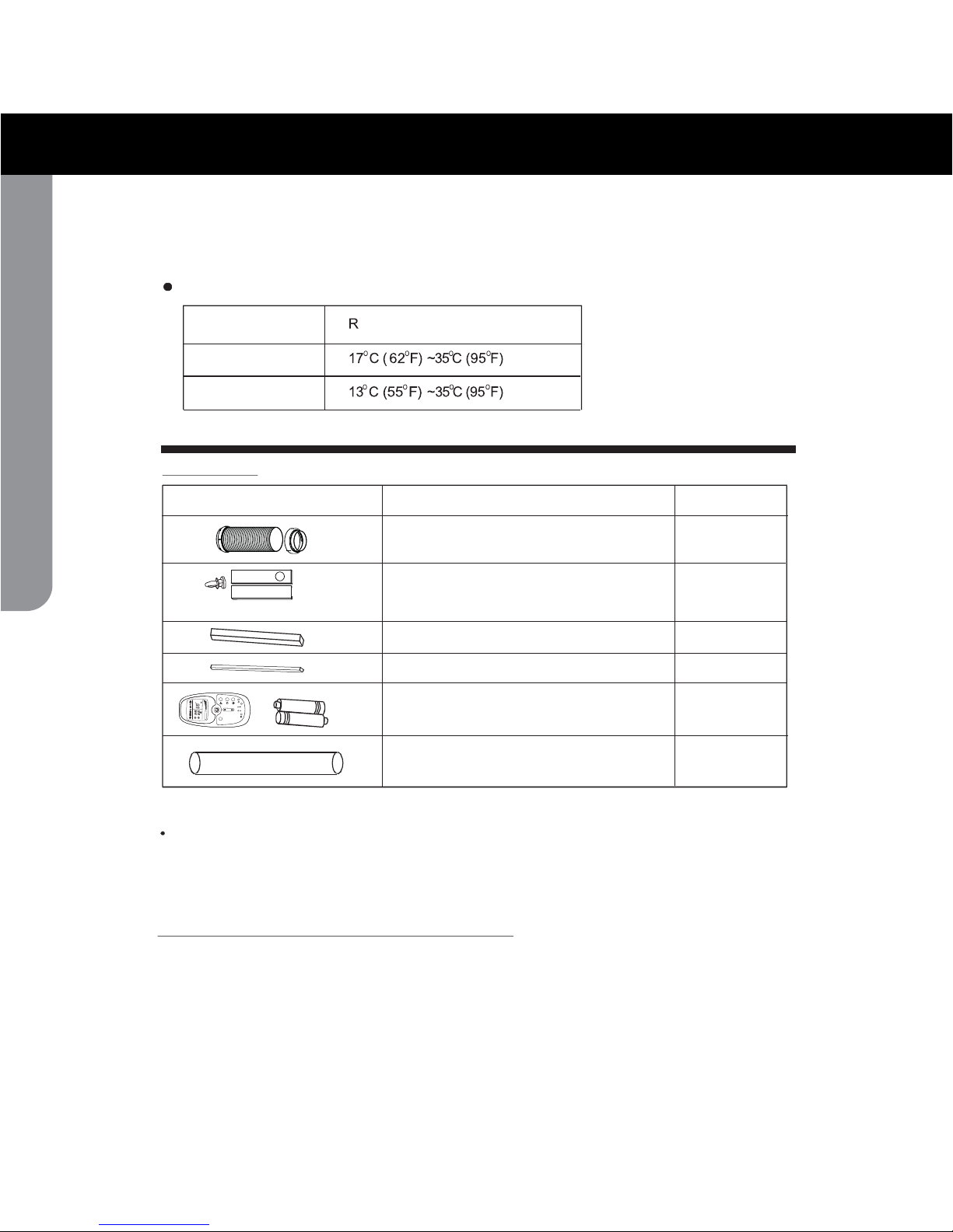
Accessories
PART S
YTITNAUQEMANSTRAP
Foam seal
Exhaust hose , adapter (flat mouth)
Window slider kit and bolt
1 set
1 set
Check that all the accessories are included in the package and please refer to the installation instructions
for their usage.
All illustrations in this manual are for explanation purposes only.Your air conditioner
may be slightly different. The actual unit shall prevail.
NOTE:
Remote control and battery
(For models with remote control only)
1 set
Drain hose
1 pc
(non-adhesive type)
Foam seal
(adhesive type)
Suggested tools for window kit installation
1. S crewdriv er(medium si z e Phillips )
2. Tape measure or ruler
3. K nife or scissor s
4. S aw (In the eve nt tha t the win dow k it ne e ds to be cut dow n in siz e beca use
the wi n dow is to o narrow for di rect insta lla tion )
The air conditioner must be operated within the temperature range indicated below:
Operating conditions
MODE OOM TEMPERATURE
COOL
DRY
No t e : Perfor m ance may be reduc ed outside of t hese o perati ng t empera t u res.
(The bolt is in the poly bag containing
the instruction manual)
M
O
D
E
L
E
D
C
L
O
C
K
C
O
N
O
F
F
S
E
T T
E
M
P
.
F
A
N S
P
E
E
D
A
U
T
O
F
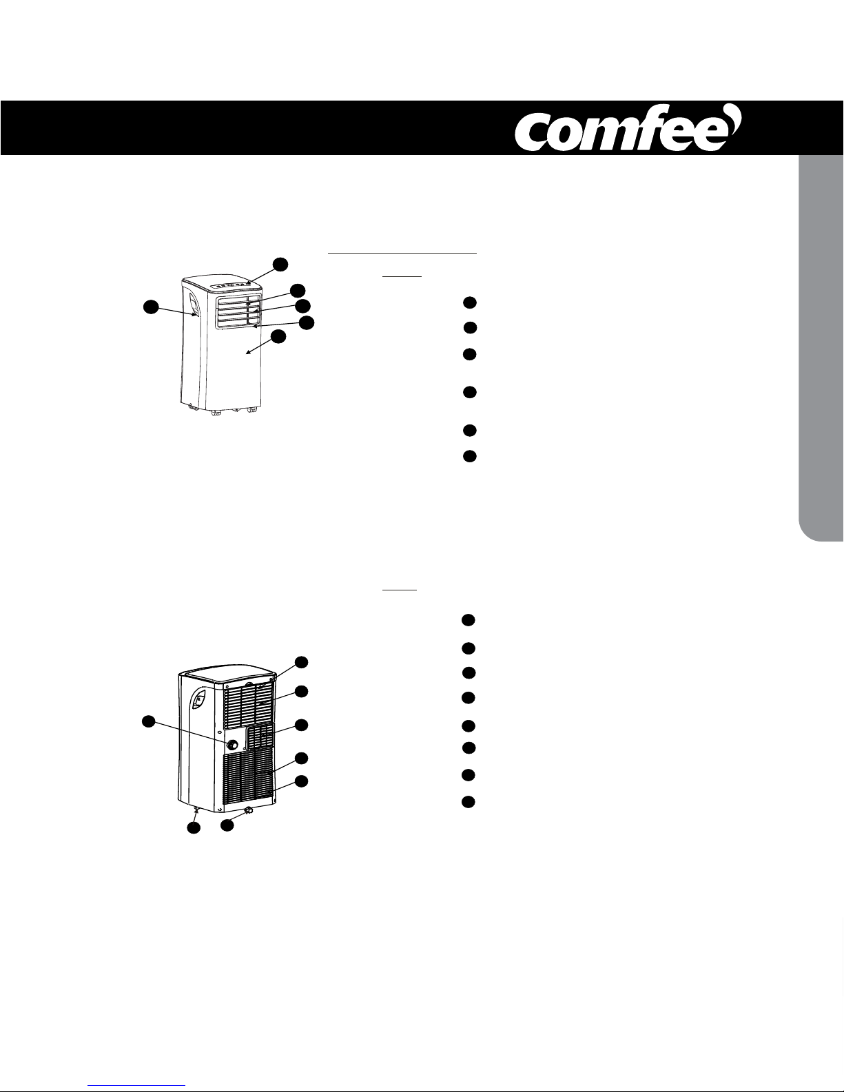
IDENTIFICATION OF PARTS
1 pcs
2 pcs
model no. MPPH-06CRN1-BI0 | contact us: 1.866.646.4332
Page 5
5
Operation Panel
Remote Signal Receptor
Horizontal Louver Control Lever
(adjust manually)
Vertical Louver Control Lever
(adjust manually)
Panel
Carrying Handle
(both sides)
1
2
3
Fig.1
Fig.2
8
9
12
13
Upper Air Filter
(Behind the grille)
Air Outlet
Lower Air Filter
(Behind the grille)
14
4
Bottom tray drain outlet
7
Air Intake
Air Intake
Drain Outlet
1
2
6
5
8
7
9
12
13
14
3
4
5
6
10
11
10
11
NAMES OF PARTS
Front
Rear
Casters
IDENTIFICATION OF PARTS
Page 6
6
Fig.3
11
22
33
44
22
Power indicator
light
Timer mode indicator
light (set only by remote
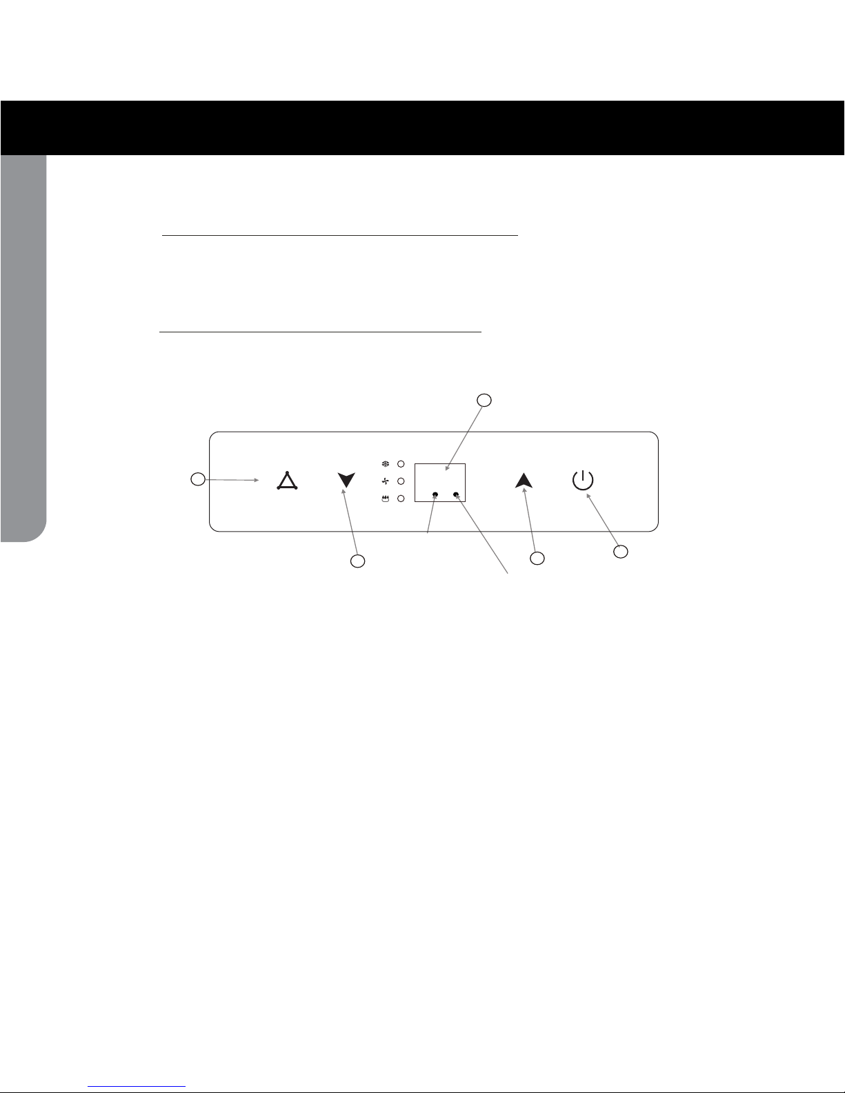
ELECTRONIC CONTROL OPERATING INSTRUCTIONS
OPERATION PANEL OF THE AIR CONDITIONER
Before you begin, get fully familiar with the control panel and remote control and all their
functions, then follow the symbol for the functions desired.
The unit can be controlled by the unit control panel alone or with the remote control .
NOTE: For instructions on how to use the remote control, please see page 15 of this manual.
control)
AIR CONDITIONER FEATURES
model no. MPPH-06CRN1-BI0 | contact us: 1.866.646.4332
Page 7

7
OPERATING INSTRUCTIONS
While on DRY and FAN modes, it shows the room
temperature.
E2- Evaporator temperature sensor error Unplug the unit and plug it back in.
If error repeats, call for service.
E4- Display panel communication error-
Unplug the unit and plug it back in.
If error repeats, call for service.
Error codes:
E1- Room temperature sensor error-
Unplug the unit and plug it back in.
If error repeats, call for service.
Protection codes:
P1- Bottom tray is full - Connect the
drain hose and drain the collected
water away. If error repeats, call
for service.
- Press the "MODE" button until the "COOL"
indicator light comes on. The unit will operate
the auto fan speed automatically.
- Press the ADJUST buttons " " or " " to
select your desired room temperature. The
temperature can be set within a range of
OOOO O
17 C-30 C/62 F-88 F(or 86 F).
- Press the "FAN" button on the remote cotroller
- Press the "MODE" button until the "DRY"
indicator light comes on.
- Under this mode, you cannot select a fan
speed or adjust the temperature. The fan
- Keep windows and doors closed for the best
dehumidifying effect.
- Do not put the duct to window.
- Press the "MODE" button until the "FAN "
indicator light comes on. The unit will operate
the auto fan speed automatically. The
temperature cannot be adjusted on fan mode.
- Press the "FAN" b utton on the remote control
- Do not put the duct to window.
This feature can be activated from the
remote control ONLY.
NOTE: When more than one
error occurs,
the priority of the code display order is:
E4--E2--E1--P1.
motor operates at LOW speed.
Sh ows th e s et temp erature in CO" "
" "orF an d the Aut o-tim e r setti ngs.
O
UP( ) and DOWN( ) button
2
1
MODE select button
ON-OFF button
4
Operating Instructions
COOL operation
DRY operation
FAN operation
SLEEP operation
3
LED Display
Selects the appropriate operating mode.
Each time you press the button, a mode
is selected in a sequence that alternates
between COOL, FAN and DRY. The mode
indicator light illuminates under the different
mode settings.
(Fig.3).
NOTE: On above modes, the unit operates the
auto fan speed automatically. You can set fan
speed only with the remote control, on COOL
and FAN modes.
to set the fan speed.
Used to adjust (increasing/decreasing)
O O
temperature s ettings in 1 C/2 F i nc rements
O O O O
in a range of 17 C/62 F to 30 C/88 F.
NOTE: The control can display temperature
in degrees Fahrenheit or degrees Celsius.
To convert from one to the other, press and
hold the Up and Down buttons at the same
time, for 3 seconds.
to set the fan speed.
When the SLEEP feature is selected, the set
temperature
O O O
will increase by 1 C/2 F(or 1 F)
in 30 minutes.The set temperature will then
increase by
O O O
another 1 C/2 F(or 1 F) after an
additional 30 minutes. This new temperature
will be maintained for 7 hours before it returns
to the initial temperature. This ends the Sleep
mode and the unit will continue to operate as
originally programmed.
Used to turn thepower off or on.
DRY mode. The room temperature may increase
over 30 C under sleep mode.
O
NOTE: This feature is unavailable under FAN or
Page 8
8
Fig.4
Adjust
manually
Adjust
manually
If the unit turns off unexpectedly due to a
power outage or interruption, it will restart
automatically with its previous settings when
the power resumes.
After the unit has stopped, it cannot be restarted
in the first 3 minutes. This is to protect the unit.
Operation will automatically start after3 minutes.
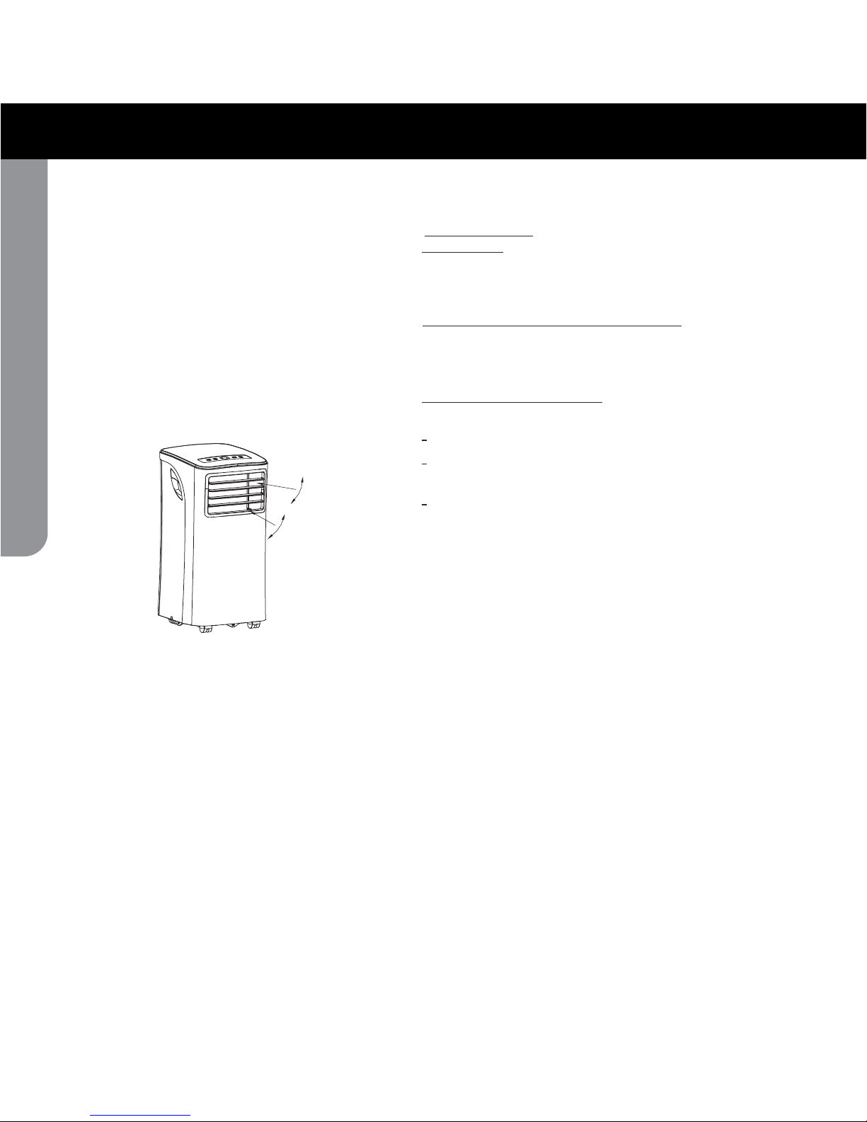
Adjust the air flow direction manually
(Fig.4):
The louvers can be set to the desired position
manually.
Do not place any heavy objects or other loads
on the louvers; doing so will cause damage to
the unit.
Keep the louvers fully opened during
operation.
Other features
Auto-Restart
Wait 3 minutes before resuming operation
Air flow direction adjustment
OPERATING INS TRUCTIONS
model no. MPPH-06CRN1-BI0 | contact us: 1.866.646.4332
Page 9

9
INSTALLATION INSTRUCTIONS
A:
30cm (11.8")-100cm (39.4")
B:
30cm (11.8")
INSTALLATION INSTRUCTIONS
LOCATION
Window Slider Kit Installation
Fig.5
bolt
Wind ow slider kit
Horizontal
window
Horizon ta l
win dow
.)"6.62 ( mc5.76
Wi ndow Slider K it
.)"6.62 ( mc5.76
Wi ndow Slider K it
Fig.7a
Fig.6
Fig.7
The air conditioner should be placed on a firm
foundation to minimize noise and vibration. For
safe and secure positioning, place the unit on a
smooth, level floor strong enough to support the unit.
The unit has casters for easier placement, but it should
only be rolled on smooth, flat surfaces. Use caution
when rolling on carpeted surfaces. Do not attempt to
roll the unit over objects.
The unit must be placed within reach of a properly
rated, grounded socket.
Never place any obstacles
around
the air inlet or
outlet of the unit.
of space
from the wall for efficient air-conditioning
(see Fig.5)
.
Yo ur window slider kit has been designed to fit most
applications. However, it may be necessary for you to
improvise/modify some aspects of the installation
procedures for certain types of window. Please refer
to Fig. 6& Fig.7 for minimum and maximum window
openings.Window slider kit can be attached with a bolt
(see Fig.7
a).
vertical
A
B
Allow at least
11.8" (30 cm) to 39.4" (100 cm)
hole A
The other piece of window slider kit would not be necessary.
Hole A
A in the
48.4''(123.0cm).
48.4''(123.0cm).
Page 10

INSTALLATION INSTRUCTIONS
10
1. Cut the foam seal (adhesive type) to the proper
length and attach it to the windowsill. See Fig.8
2. Attach the window slider kit to the windowsill.
Adjust the length of the window slider kit according
to the width of window, shorten the adjustable window
kit if the width of window is less than 26.6 inches.
Open the window sash and place the window slider
kit on the windowsill. Fig.9.
3. Cut the foam seal (adhe
sive type) to the proper
length and attach it on the top of the window kit.
See Fig.10.
4. Close the window sash securely agains
t the
window kit.
5. Cut the foam seal to an
appropriate length and seal the open gap
retuodnahsaswodniwdesolc potehtneewteb
window sash. See Fig.11.
Foam seal A
(adhesive type)
Window kit
windowsill
Foam seal
Fi g. 8
Fig.9
Fi g.1 0
Fig.11
Window kit
windowsill
Installation in a double-hung sash
window
(non-adhesive type)
(non-adhesive type)
26.6"(67.5cm)~48.4"(123.0cm).
model no. MPPH-06CRN1-BI0 | contact us: 1.866.646.4332
Page 11

INSTALLATION INSTRUCTIONS
11
Installation in a sliding sash window
1. Cut the foam seal A (adhesive type) to the proper
length and attach it to the window frame. See Fig.12.
2. Attach the window slider kit to the windowsill.
Adjust the length of the window slider kit according
to the width of window, shorten the adjustable window
kit if the width of window is less than 26.6 inches.
Open the window sash and place the window slider
kit on the windowsill. See Fig.13.
3. Cut the foam seal (adhesive type) to the proper
length and attach it o
n the top of the window kit .
See Fig.14.
4. Close the sliding sash securely against the window kit.
5. Cut the foam seal (non-adhesive type)
(non-adhesive type)
to an
appropriate length and seal the open gap
between the window sash and
outer window sash. See Fig.15.
Foam seal
Foam seal A
(adhesive type)
Window
panel
Fi g. 12
Fi g.13
Fig.14
Fig.15
closed side
26.6"(67.5cm)~48.4"(123.0cm).
Page 12

12
Ex haust hose installation:
The exhaust hose and adaptor must be installed or removed
in accordance with the installation of the unit.
Th e duct can b e com pressed or e xtended mo derate ly
ac cordin g to th e installation requirements, but it is
preferable to ke ep the duct length to a minim um.
IMPORTANT:
DO NOT OVER
Fig.1 7
Note:
Cover theholef or theadaptor capwhennotin use.
Fig.1 6
COOL or AUTO mode
FAN
DEHUMIDIFY
or mode
Install
Remove
Fi g.18
1. Install the window exhaust adaptor B ont o the exhaust
hose as shown in Fig.1 Refer to the previous
pages for window kit installation.
2. Push theexhaust hose into the airoutlet opening along
the arrow direction(See Fig.1
6.
7).
18)
-
BEND THE DUCT (SEE Fig.
INSTALLATION INSTRUCTIONS
model no. MPPH-06CRN1-BI0 | contact us: 1.866.646.4332
Page 13

13
-
When the water levelinthe bottom tray reaches
a predetermined level,
Carefully move the unit to a drain location,
remove the bottom drain plug and let the
water drain away (Fig.2
1
). Reinstall the bottom
drain plug and restart the machine until the P1
symb
ol disappears. If the error repeats, call for
service.
" "
the unit beeps 8 times and
the digital display area shows P1 . At this time
the air conditioning/dehumidification process will
immediately stop. However, the fan motor will
continue to operate (this is normal).
" "
Fig.19
Fig.20
Fig.21
Water drainage:
R emov e the
drain p lug
Con ti nu ou s
dra in h os e
Bo tto m dr a in p lug
plug from the back of the unit. You may also
connect a 3/4" (1.9cm) garden hose (sold
separately) onto the 5/8" (1.58cm) drain
connector on the unit. For models without a
drain connector, just attach the drain hose to
the hole. Place the open end of the hose directly
over the drain area in your basement floor.
Please refer to Fig.19 & 20.
I n dehumidifying mode,remove the drain
INSTALLATION INSTRUCTIONS
Page 14

14
Fig.22
1) Be sure to unplug the unit before cleaning or servicing.
2) Do not use gasoline, thinner or other chemicals to clean
the unit.
IMPORTANT:
1. Air filter
- Clean the air filter at least once every two weeks to prevent
- Removal
Take the air filter out along the arrow direction (Fig.22).
- Cleaning
Wash the air filter by immersing it gently in warm water
OO
(about 40 C/104 F) with a neutral detergent. Rinse the filter
and dry it in a shady place.
- Mounting
Install the air filter after cleaning (see Fig.23).
2. Unit enclosure
- Remove the rubber plug at the back of the unit and attach
a hose to drain outlet. Place the open end of the hose
directly over the drain area in your basement floor
(See Fig.19 & 20).
- Remove the plug from the bottom drain outlet, all the water
in the bottom tray will drain out (See Fig.21).
- Keep the appliance running on FAN mode for half a day in
a warm room to dry the appliance inside and prevent mold.
- Stop the appliance and unplug it, wrap the cord and
bundle it with the tape. Remove batteries from
the remote control.
- Clean the air filter and reinstall it.
NOTE:
Fig.23
Air filter
(install)
Air filter
(take out)
CARE AND MAINTENANCE
3) Do not wash the unit directly under a tap or using a hose.
It may cause electrical shock.
4) If the power cord is damaged, it should be repaired/replaced
by the manufacturer or its authorized agent.
dust from affecting fan operation.
- Use a lint-free cloth soaked with neutral detergent to clean
the unit enclosure. Dry enclosure with a clean cloth.
3. If the unit will not be used for a long time
The grill and the air filter are connected but can be
separated.
CARE AND MAINTENANCE
model no. MPPH-06CRN1-BI0 | contact us: 1.866.646.4332
Page 15

15
T R O U B L E S H OOTI N G
1. Uni t does no t
start when
pr es s ing on /of f
butt o n
TROUBLES
POSSIBLE CA USES
SUGGEST REMEDIES
Reset the temperature.
Make sure all the windows and
doors are closed.
Remove the heat sources if possible.
Connect the duct an d make
sure it can function properly.
Decrease t he set temperature.
Clean the air filter.
- Room temperature is lower tha n
the set temperature.(Coo ling mode)
- The windows or doors in the room
are not closed.
- Ther e are heat sources inside the
room.
- Exhaust air duct is not connected or
is blocked.
- Temperature setting is too high.
- Air filter is blocked by dust.
2. Air is not cool enough
Place the unit on a f lat, level
floor if poss ible.
This s ound i s normal.
- The floor is not level or no t flat
enough.
- The sound comes from the
refrigerant flowing inside the
air conditioner.
4. Nois e o r vibra ti on
5. Gu rg ling sound
Swi tch on ag ain after the unit
has cool down.
- Caused by t h e uni t's ov erheating
protect ion f unct ion .
Whe n the
t emper at ure at t h e a ir ou t le t
e x ceeds 70 C/15 8 F,the unit
wi l l s to p .
O O
6. Power shu t o ff in
heating m od e
- P1 appears in the display window
Drain th e water in the botto m tray.
TROUBLESHOOTING TIPS
Page 16

16
Model
Transmission Distance
Lowest Voltage of
CPU Emitting Signal
Rated Voltage
8m
2.0V
Environment
Specification
。 。
O O
-5 C 60 C(-41 F~140 F)
RG09E/BGCE
3.0V(Dry batteries R03/LR03×2)
C
L
O
C
K
C
O
N
O
F
F
S
E
T TE
M
P
.
F
A
N S
P
E
E
D
A
U
T
O
F
~
REMOTE CONTROL INSTRUCTIO
model no. MPPH-06CRN1-BI0 | contact us: 1.866.646.4332
Page 17

17
Features of remote control
1
ON/OFF Button: Push this button to start operation, push
the button again to stop operation.
2
MODE Select Button: Each time you push the button, a mode
is selected in a sequence that goes from AUTO, COOL,
DR
Y
and F
AN, as the following figure indicates:
AUTO
COOL
DRY
FAN
1
2
3
4
5
6
7
8
9
1
0
11
C
L
O
C
K
C
O
N
O
F
F
S
E
T T
E
M
P
.
F
A
N S
P
E
E
D
A
U
T
O
F
3
TEMP/TIME Button : Push the button to increase the
indoor temperature setting or to adjust the TIMER in a clockwise
direction. Push the button to decrease the indoor
REMOTE CONTROL INSTRUCTIO
Page 18

18
Features of remote control(continued)
RESET Button: When you press the recessed RESET button,
all current settings are cancelled and the control will return to
the initial settings.
FAN Button: Used to select the Fan Speed in four stepsAUTO、LOW 、MED(some models without) or HIGH. Each
time the button is pressed, the fan speed mode is shifted.
temperature setting or to adjust the TIMER in a counter-clockwise
direction.
NOTE: Press and hold and buttons together for 3 seconds
will alternate the temperature display between the C & F scale.
TIMER Button: This button is used to preset the time ON
(start to operate) and the time OFF (turn off the operation).
LOCK Button: When you press the LOCK button, all current
settings are locked in and the remote controller does not accept
any operation except that of the LOCK. Press again to cancel
the LOCK mode.
CANCEL Button:
(a). If the TIMER ON, TIMER ON OFF or TIMER OFF ON
feature has been set, press the CANCEL button will override
the TIMER program and turn off the unit as well.
(b). If only set TIMER OFF feature, press the CANCEL button
will cancel the timer off setting and turn on the unit (when
the unit is off).
(c). If no TIMER feature has been set, press the CANCEL button,
and nothing will happen.
CLOCK Button: Use to set the time.
LED Button: Press this button to clear the digit display in the
air conditioner, press it again to activate it .
SLEEP Button: In SLEEP mode,
Active/Disable sleep function. It can maintain the most
comfortable temperature and save energy. This function is
available on COOL or AUTO mode only. For the detail,
see Sleep operation in USER S MANUAL.
,,,
NOTE:
be cancelled if MODE, FAN SPEED or ON/OFF button is
pressed.
While the unit is running under SLEEP mode, it would
,,,,
,,
6
5
7
9
8
10
11
4
REMOTE CONTROL INSTRUCTIO
model no. MPPH-06CRN1-BI0 | contact us: 1.866.646.4332
Page 19

19
CL OC K
C
ON
OF F
SE T TE MP.
FA N SPE ED
Indicators on remote controller
Transmission Indicator
Temp. display
Time display
Fan speed display
Sleep Display
Mode display
ON/OFF display
This transmission indicator lights when
remote controller transmits signals to the
indoor unit.
Displays the current operation mode. Including
AUTO( ), COOL( ), DRY( )
, F
AN
ONLY ( )and back to AUTO( ).
。
Displays the temperature setting (17 C/62 F
to 30 C/86 F)when you set the operating
mode to FAN ONLY, no temperature setting is
displayed.
Displayed by pressing the ON/OFF button.
Press the ON/OFF button again to remove.
The clock time is indicated only when no
AUTO-ON/OFF timer is set. When AUTOTIMER feature is operating, it displays the
AUTO-ON/OFF time. To check the current
time, press the CLOCK button, and the time
will display.
Indicate Timer on/off time(0 24 hours)
or clock time.
Displays the selected fan speed, AUTO
and three fan speed levels " " (LOW)
" " (MED) " " (HIGH)
can be indicated. Displays AUTO when the
operating mode is either AUTO or DRY.
Displayed by pressing the SLEEP button.
Press the SLEEP button again to remove.
Note:
All displays on the remote controller are
shown for illustration purposes only.
AUTO
F
AUTO
AUTO
Lock Display
Displayed by pressing the LOCK button.
Press the LOCK button again to remove.
~
Note: Some models have no MED Fan
speed selection.
REMOTE CONTROL INSTRUCTIO
Page 20

20
Keep the remote controller where its
signals can reach the receiver of the
unit (a distance of 8m is allowed).
When you select the timer operation, the
remote controller automatically transmits
a signal to the indoor unit at the specified
time.
If you keep the remote controller in a
position that hinders proper signal
transmission, a time lag of up to 15
minutes may occur.
Location of the remote controller.
.
.
8m
CAUTIONS
The air conditioner will not operate if curtains, doors or other materials
block the signals from the remote controller to the indoor unit.
Prevent any liquid from falling into the remote controller. Do not expose
the remote controller to direct sunlight or heat.
If the infrared signal receiver on the indoor unit is exposed to direct
sunlight, the air conditioner may not function properly. Use curtains to
prevent the sunlight from falling on the receiver.
If other electrical appliances react to the remote controller. either move
these appliances or consult your local dealer.
.
.
The remote controller uses two
dry batteries (R03/LR03X2)
(1) Slide the cover of the battery
compartment off according to the
arrow direction, then replace the
old batteries with new ones.
(2) Insert the new batteries making
sure that the(+) and (-) of battery
are installed correctly.
(3) Reattach the cover by sliding it
back into position.
After replacing batteries, set the
remote controller clock.
Replacing batteries
.
.
.
Handling the remote controller
Do not recharge batteries or dispose of them in fire.
Battery disposal-please dispose the used battery per municipal or provincial law.
protect the environment
containers to
REMOTE CONTROL INSTRUCTIO
model no. MPPH-06CRN1-BI0 | contact us: 1.866.646.4332
Page 21

21
Before you start operating the air conditioner,
set the clock of the remote controller using
the procedures given in this section. The
clock panel on the remote controller will
display the time regardless of whether the
air conditioner is in use or not.
After batteries are inserted in the remote
controller, the clock panel will display "12:00".
Press and hold the CLOCK button for 3nds,
the time begin to flash.
1. TEMP/TIME adjust button
Press this button to set time.
Forward.
Backward.
Each time you press the button, the time
moves forward or backward by one minute
depending on which side you press.
The time alters as quickly as you push the
button.
Keep pressing the button without releasing,
the time moves forward or backward by 10
minutes depending on which side you press.
Initial Setting or the Clock
.
.
When the right time is achieved, press the
CLOCK button or release the or and
wait for 5 seconds, the clock time stops
flashing and the clock starts operating.
Press the CLOCK button on the remote
controller for about 3 seconds, the clock
display time will start to flash.
To set the new time, follow 1 and 2 of "Initial
Setting of the Clock".
Note: The time of the CLOCK must be set
before the AUTO-TIMER feature will operate.
If you readjust the time of the CLOCK after
setting the AUTO-ON/OFF timer, the remote
controller will send the readjusted timer
information to the unit.
* Clock accuracy is within 15 seconds per day.
2.
3.Readjusting the Clock
Static electricity or other factors (in case of extremely high voltage) can
cause remote controller clock initialize. If your remote controller is
initialized (flashing "12:00"), readjust the clock before you start operation.
CAUTIONS
.
CL OC K
CLOCK button
Setting the clock
1
CLOCK
SET TEM P.
FAN SP EED
AUTO
2
C
REMOTE CONTROL INSTRUCTIO
Page 22

22
Automatic operation
Ensure the unit is plugged in and power
is available. The OPERATION indicator
on the display panel of the indoor unit
starts flashing.
1. Mode select button (MODE)
Press to select AUTO.
2. TEMP/TIME button
Set the desired temperature. Normally,
。 。
set it between 21 C/ to 2 8 C/83 F.
3. ON/OFF button
When the remote controller is off,
push this button to start the air
conditioner.
O
70 F
ON/OFF button
Push this button again to stop the air
conditioner.
If the AUTO mode is uncomfortable, you
can select the desired conditions manually.
When you select the AUTO mode, you do
not have to set the fan speed. The fan
speed will be automatically controlled.
When you set the air conditioner in AUTO
mode, it will automatically select cooling,
or
fan only operation depending on what
temperature you have selected and the
room temperature.
Once you select the operating mode, the
operating conditions are saved in the
unit's microcomputer memory
.
Thereafter, the air conditioner will start
operating under the same conditions
when you simply push the ON/OFF
button of the remote controller
.
Start
Stop
1
2
CLOC K
SET TE MP.
FAN SP EED
AUTO
3
C
REMOTE CONTROL INSTRUCTIO
model no. MPPH-06CRN1-BI0 | contact us: 1.866.646.4332
Page 23

23
DRYING OPERATION
Ensure unit is plugged and power is available.
The OPERATION lamp on the display panel of
the indoor unit starts flashing.
1. Mode select button (MODE)
Press to select COOL,
FAN ONLY
ON/OFF button
Push this button again to stop the air conditioner.
The FAN ONLY mode does not control temperature.
Therefore, perform only steps 1,3, and 4 to select
this mode.
Ensure unit is plugged and power is available.
The OPERATION indicator on the display panel
of the indoor unit starts flashing.
1. Mode select button (MODE)
Press to select DRY.
2. TEMP/TIME button
Push the "TEMP/TIME" button to set the desired
。
O o O
temperature from 21 C/70 F to 28 C/83 F.
3. ON/OFF button
When the remote controller is off, push this
button to start the air conditioner.
ON/OFF button
Push this button again to stop the air conditioner.
2. TEMP/TIME button
Set the desired temperature, the most comfortable
。 O 。
temperature is between 21 C/70 F to 2 8 C/83 F.
3. Fan speed button (FAN SPEED)
Press to select "AUTO" "LOW", "MED" and "HIGH"
4. ON/OFF button
When the remote controller is off, push this
button to start the air conditioner.
Start
Stop
Start
Stop
Note: The fan speed cannot be adjusted when
the unit is in AUTO and DRY mode.
Cooling/Fan only operation
1
2
4
3
CLOCK
SET TEM P.
FAN SPE ED
1
2
3
CLOCK
SET TEM P.
FAN SPE ED
C
C
REMOTE CONTROL INSTRUCTIO
Page 24

24
Timer operation
When you select the timer operation, the remote controller automatically
transmits the timer signal to the indoor unit at the specified time.
Therefore, keep the remote controller in a location from which it can
transmit the signal to the indoor unit properly.
The effective operation time set by remote controller is limited in 24 hours.
CAUTIONS
1. TIMER button
Press the TIMER button, the remote
displays 0.0 alongside either the TIMER
ON or TIMER OFF indicator, and will
flash.
2. TEMP/TIME button
Press to set the desired time.
Forward
Backward
Press or hold the forward or backward
button to change the Auto time by 0.5
hour increments, up to 10 hours, then
at 1 hour increments up to 24 hours.
The selected time will register in 3nds
after setting.
3. After setting the timer for TIMER ON and
TIMER OFF, check the TIMER indicator
on the display panel of the unit is
illuminated.
4. Cancel button(CANCEL)
Press the CANCEL button to cancel
the timer setting.
Preform steps 1, 2 and 3 to change the
settings.
.
.
Canceling
Changing
.
.
1
2
3
ON
OFF
SET TE MP.
FAN SP EED
.
C
REMOTE CONTROL INSTRUCTIO
model no. MPPH-06CRN1-BI0 | contact us: 1.866.646.4332
Page 25

25
(Timer Stop Operation)
The TIMER OFF feature is useful
when you want the unit to turn off
automatically after you go to bed.
The air conditioner will stop automatically at the set time.
To stop the air conditioner in 6 hours.
1. Press the TIMER button until the
TIMER OFF indicator is displayed
and the setting time beside is flashing.
2. Use the TEMP/TIME button to display
"6.0" beside the TIMER OFF display.
3. This function will be activated after 3
seconds you release the TEMP/TIME
button.
TIMER OFF
Example:
(Timer Start Operation)
The TIMER ON feature is useful when
you want the unit to turn on automatically
before say when you return home.
The air conditioner will automatically
start operating at the set time.
IMPORTANT: The time will be registered
within a 3 second period(after pressing
the TEMP/TIME button), so you should
continue pressing the button until the
desired time is established. Otherwise
you must repeat the steps again.
To start the air conditioner in 8 hours.
1. Press the TIMER button, the TIMER
ON indicator is displayed and the
setting time beside is flashing.
2. Use the TEMP/TIME button to display
"8.0" beside the TIMER ON display
of the remote control.
3. Wait for 3 seconds and the setting time
stops flashing and this function is
activated.
TIMER ON
Example:
Example of timer setting
ON
OF F
Start
Off
8 hours later
Set
Stop
On
Set 6 hours later
REMOTE CONTROL INSTRUCTIO
Page 26

To stop the air conditioner 2 hours after
setting and start it again 10 hours after
setting.
1. Press the TIMER button until the TIMER
OFF indicator is displayed and time setting
is flashing.
2. Use the TEMP/TIME button to display
"2.0" beside the TIMER OFF display.
3. Press the TIMER button again to display
the TIMER ON .
4. Use the TEMP/TIME button to display
"10" beside the TIMER ON display.
5. Wait for 3 seconds until the TIMER ON
time stops flashing and this function
is activated.
TIMER OFF → TIMER ON
(On → Stop → Start operation)
This feature is useful when you want to
stop the air conditioner after you go to
bed, and start it again in the morning
when you wake up or when you return
home.
Example:
COMBINED TIMER
(S both ON and OFF
simultaneously)
etting timers
Example:
TIMER ON → TIMER OFF
(Off → Start → Stop operation)
This feature is useful when you want to start
the air conditioner before you wake up and
stop it after you leave the house.
To start the air conditioner 5 hours after
setting, and stop it 8 hours after setting.
1. Press the TIMER button, the TIMER ON
displays and the setting time flashes.
2. Use the TEMP/TIME button to display
"5.0" beside the TIMER ON display of the
remote controller.
3. Press the TIMER button again to display
the TIMER OFF and the setting time.
4. Use the TEMP/TIME button to display
"8.0" beside the TIMER OFF display.
5. Wait for 3 seconds until the TIMER OFF
time stops flashing and this function
is activated.
ON
OF F
ON
OF F
On
Stop
2 hours later
after setting
Set
Start
10 hours later
after setting
Off
Stop
Start
5 hours later
after setting
8 hours later
after setting
Set
26
REMOTE CONTROL INSTRUCTIO
model no. MPPH-06CRN1-BI0 | contact us: 1.866.646.4332
Page 27

27
Air Conditioner Limited Warranty
Your product is protected by this Limited Warranty
:
Warranty service must be obtained from Midea Consumer Services or an authorized Midea servicer.
Warranty
•
One year full warranty from original purchase date.
•
Limited 2nd through 5th year sealed system warranty*
, through its authorized servicers will:
•
Pay all costs for repairing or replacing parts of this appliance which prove to be defective in materials or workmanship.
•
*For limited 2nd through 5th year sealed system warranty, will replace any part in the sealed refrigeration
system (compressor, condenser, evaporator and tubing) which proves to be defective in materials or workmanship.
Consumer will be responsible for:
•
Diagnostics, removal, transportation and reinstallation cost required because of service.
•
Costs of service calls that are a result of items listed under NORMAL RESPONSIBILITIES OF THE CONSUMER**
Midea replacement parts shall be used and will be warranted only for the period remaining on the original warranty.
NORMAL RESPONSIBILITIES OF THE CONSUMER**
This warranty applies only to products in ordinary household use, and the consumer is responsible for the items listed
below:
1. Proper use of the appliance in accordance with instructions provided with the product.
2. Routine maintenance and cleaning necessary to keep the good working condition.
3. Proper installation by an authorized service professional in accordance with instructions provided with the
appliance and in
accordance with all local plumbing, electrical and / or gas codes.
4. Proper connection to a grounded power supply of sufficient voltage, replacement of blown fuses, repair of loosen
connections or defects in house wiring.
5. Expenses for making the appliance accessible for servicing.
6. Damages to finish after installation.
EXCLUSIONS
This warranty does not cover the following:
1) Failure caused by damage to the unit while in your possession (other than damage caused by defect or
malfunction), by its improper installation, or by unreasonable use of the unit, including without limitation, failure to
provide reasonable and necessary maintenance or to follow the written Installation and Operating Instructions.
2) Damages caused by services performed by persons other than authorized Midea servicers; use of parts other than
Midea replacement part
s; obtained from persons other than such Midea customer service; or external causes such
as abuse, misuse, inadequate power supply or acts of
God.
3) If the unit is put to commercial, business, rental, or other use or application other than for consumer use, we make
no warranties, express or implied, including but not limited to, any implied warranty of merchantability or fitness for
particular use or purpose.
4) Products without original serial numbers or products th
at have serial numbers which have been altered or cannot be
readily determined.
Note: Some states do not allow the exclusion or limitation of incidental or consequential damages. So this limitation or
exclusion may not apply to you.
IF YOU NEED SERVICE
Keep your bill of sale, delivery slip, or some other appropriate payment record.
The date on the bill establishes the warranty period, should service be required.
If service is performed, it is your best interest to obtain and keep all receipts.
This written warranty gives you specific legal rights. You may also have other rights that vary from state to state.
Service under this warranty must be obtained by following these steps, in order:
1. Contact Midea Consumer Services or an authorized Midea servicer at 1 866 646 4332
2. If there is a question as to where to obtain service, contact our consumer relations Department.
Midea
Midea
 Loading...