

Page 1
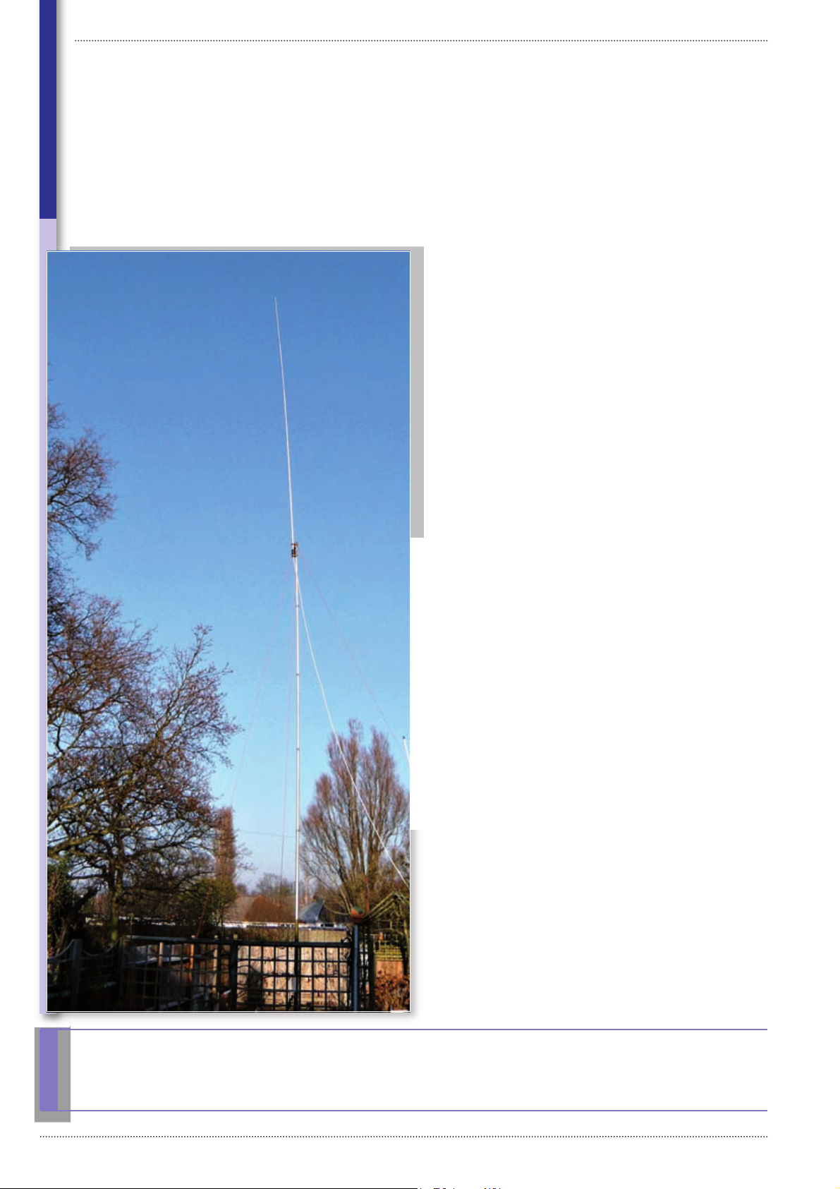
An h.f vertical antenna for ‘postage-stamp’ garderns.
The Comet CHA-250BX
Reveiw
Broadband GP Antenna
The Comet CHA-250BX antenna,
can be a useful antenna for those of
us who have postage-stamp sized
gardens as it doesn’t need radials.
he CHA-250BX is
described by the
T
a ground-plane antenna.
It’s essentially a multiband vertical covering
3.5-50MHz (80m-6m)
working against ground.
But it doesn’t require any
radials or earth connection.
General advertising
sources suggest it’s the
ideal antenna where there
is restricted space. (More
on this later).
packed for transit and
arrived undamaged.
The box contained all
the pieces required for
assembly, there were no
defi ciencies which always
goes down well with me!
There are fi ve sections to
be joined and at the base
of section one is the black
housing containing what is
described as the ‘Matching
Section,’ Fig. 1.
the form of a sheet
folded (the wrong way)
and describe, in quaint
‘Jinglish’, (Japanese
English) the specifi cation
and assembly method.
Great attention is also paid
to safe practice. However,
as I removed the various
components I noticed a
lack of de-burring (sharp
edges) on the mounting
bracket and swarf had not
been removed from the
clamping split, which is
cut in the top end of the
base section. Other than
manufacturer as
The item was well
Instructions are in
these items, the general
engineering was of a good
standard.
The lower section wall
thickness is 2mm with the
matching unit at its base
terminating in an SO239
connector, the upper
end accommodates the
second section, which is
locked into position with
a substantial worm-drive
(Jubilee) screw clip round
the clamping split. The
matching unit is mounted
on a rectangular plate,
which is pre-drilled to
take two ‘U’ bolts for mast
mounting, as can be seen
in Fig. 1.
Section two has a wall
thickness of 1.8 mm. The
top end is inwardly reduced
(swaged) to accommodate
the third section.
Section three is likewise
formed and has a wall
thickness of 1.5 mm with
what appears to be a ptfe
insert at the lower end for
strength. It’s secured to the
second section through
pre-drilled holes with two
hexagon headed bolts
(M5x35) and wing-nuts.
Section four, wall
thickness 1.5 mm, is
secured to the third section
with two hexagonal headed
bolts (M4x30) and wingnuts into pre-drilled holes.
Section fi ve (also 1.5
mm) is adjustable within
the fourth section. This
is locked by two setscrews retained within two
stainless steel collars at the
Dave Mason G3ZPR has been busy evaluating a vertical antenna and despite poor
propagations conditions enjoyed himself very much!
18
Practical Wireless, March 2009
Page 2
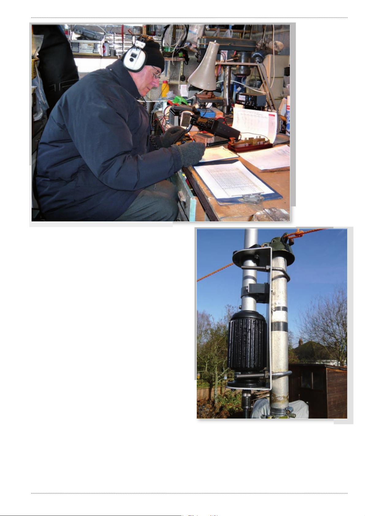
Braving a below
0°C shack to get the
propagation conditions to
check out the antenna.
Fig. 1: This is the feed-
point of the antenna,
showing the matching
section and the clamp
fi tting onto a mast.
top of the fourth section.
The instructions for
fi xing each section were
well illustrated, clear and
specifi c and the holes
for securing bolts are
accurately drilled which
make for easy assembly.
Mounting to a mast is
effected by the previously
mentioned ‘U’ bolts into
the mounting plate. These
will accommodate mast
diameters between 30 and
72mm (1.18 to 2.8in).
Note: The manufacturers
state clearly that the
antenna should be mounted
at least 10.5m (35ft) above
ground for optimum
performance.
Assembly Space
As I worked, I soon
discovered that a substantial
space is needed to
assemble the antenna,
as the total length, fully
assembled, is 7.13m (23.8
ft). Starting at the base,
I slid the second section
200 mm (8in) into the fi rst
and secured it with the
worm-drive clip around
the clamping split. The
instructions advised me that
it should be tight but not
so excessive as to strip the
clamp!
Next, I slid out section
three from within section
two until the fi xing holes
were aligned and inserted
the M5 x 35 stainless bolts.
These were then secured
with the wing-nuts. Then I
slid out section four from
within section three, aligned
the holes, inserted the bolts
(M4 x 30 this time) and
secured the section with the
wing-nuts.
The instructions then
advised that I should slide
out section fi ve completely
from section four and then
slide it back 100mm (4in)
before securing the section
with the two set-screws.
The antenna was then fully
assembled!
Mounting Method
As with any antenna, I think
that serious consideration
should be made as to
the mounting method
appropriate for the location
to be used. It was at this
point I was reminded of
advertising suggestions
relating to what might be
referred to as ‘limited space’
or, as a friend commented,
‘postage stamp’ UK gardens.
As I see it, there are three
ways of mounting a vertical
antenna 10.5 m (35ft) above
ground.
a) Fix on the apex of the
house gable with brackets
and stub mast fi xed to the
wall.
b) Attach it to a tilt-over,
crank up, mast.
c) Attach it to a pneumatic
mast.
Method (a) requires at least
Practical Wireless, March 2009
19
Page 3
The Comet CHA-250BX Broadband GP Antenna
two people and a head
for heights to fi x brackets
and a stub mast, while
working from a double/
triple extension ladder or,
preferably, a scaffold tower.
The antenna then has to
be hoisted into position
and held steady for fi xing
– remember it’s fi xed at its
base so needs to be held
very steady by an assistant
while the ‘U’ bolts are
secured around the stub
mast. Don’t forget to fi t the
feeder before dismantling
the tower!
Disadvantages: Includes
risks of working at height
(although you could use
professional antenna
erectors) and possibly
poor Electro Magnetic
Compatibility (EMC) due to
proximity of house wiring
in roof spaces and to
neighbours’ TV antennas.
Advantages: Occupies no
garden space.
Assembly hint: If your
garden really is postage
stamp sized, and you haven’t
got the room to assemble
the antenna horizontally
– it can the be assembled
vertically starting with the
top two sections (fi ve and
four) resting it against a wall
corner, with the assembly
continuing until the
complete antenna is ready to
hoist aloft.
Method (b) is much easier
if you happen to have an
existing tilt-over mast, but
here enters the problem of
garden length! The retracted
mast tilted over will be
something like 3.6m (12ft)
long, add to that, the length
of the antenna 7.3m (about
24ft) means the total length
required from the mast
base will be 10.9m (36ft)
minimum. If you have that
space, attach the feeder,
tilt up, lock, and crank to
full height – a one man job.
Disadvantage – none, if you
have one, use it. Advantages
– permanent, with less
chance of EMC problems.
Method (c) (pneumatic
mast) is the only one which
can be carried out in the
smallest of spaces and the
one chosen by me as the
easiest, most effective and
practical method. I’m lucky
enough to have the use of
such a mast but they are
very expensive if purchased
new, Fig. 2.
The antenna can be
fi xed to the mast at ground
level if about 8.8 m (29ft) is
available and then the whole
assembly can be lifted to its
fi xing points by two people.
Alternatively, it can be lifted
on to the lowered mast
using a cunning slide over
stub (Described below). The
advantages are – it requires
only the space around the
mast base. Less chance of
EMC problems. This method
has the added advantage of
ease of lowering when not in
use but, when fully erected,
the mast must be guyed, or
the base must be anchored
down suffi ciently well, Fig. 3.
Disadvantages of the
pump-up mast method of
mounting – none. But it’s
less permanent than the
tilt-over option. Remember,
a vertical is best sited well
away from other antennas
and house wiring – and keep
it high!
The Inevitable VSWR
The manufacturers of the
antenna specify a voltage
standing wave ratio (v.s.w.r.)
of less than 1.5:1 typical,
and make a point of stating
that “...before transmitting,
please check that the
VSWR is less than 1.5 at
the operating frequency.”
Initially, I found it diffi cult to
reconcile the actual values
with those stated.
The addition of an LDG
Z-100 antenna tuner unit
(a.t.u.) to the system,
(only for the purposes of
double checking) made a
considerable difference,
bringing values closer to
the those suggested. The
stated values were however,
achieved (without the a.t.u.)
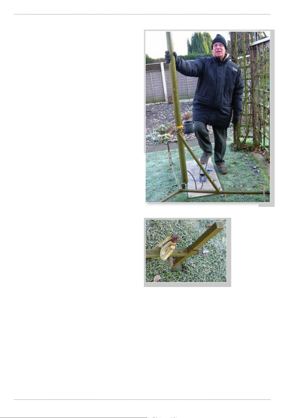
Fig. 2: Dave G3ZPR, suitably dressed, for the cold weather setting to – starts to
raise the pump-up mast in his back garden.
Fig. 3: Each leg at the
base of the pump-up mast
must be securely held in
place, in this case with
a 700mm long ground-
spike.
when I upgraded the feeder
to H100 – a better quality
and lower-loss cable. There’s
a moral in there somewhere.
Don’t skimp on feeder, it’s
really part of the antenna !
by propagation conditions.
Clearly, there’s little point in
trying to use a band when it
is effectively closed.
Despite the propagation
problems, I made every
effort to seek out the
On The Air
It was then time to see how
the antenna performed on
the air because, of course,
what’s really important for
an antenna is, it’s ability
to perform, bringing in the
signals and sending them
out to good use. However,
my tests were restricted
by the limitations infl icted
smallest opportunity of a
contact by going on air at
some ridiculous hour which
paid off. This proved to be
between 0001 and 0300
hours on 7MHz, even if it
0
was -1
C in the outdoor
shack! I had QSOs to Aruba
Island and Martinique in
the Caribbean – decidedly
warmer than my location!
20
Practical Wireless, March 2009
Page 4
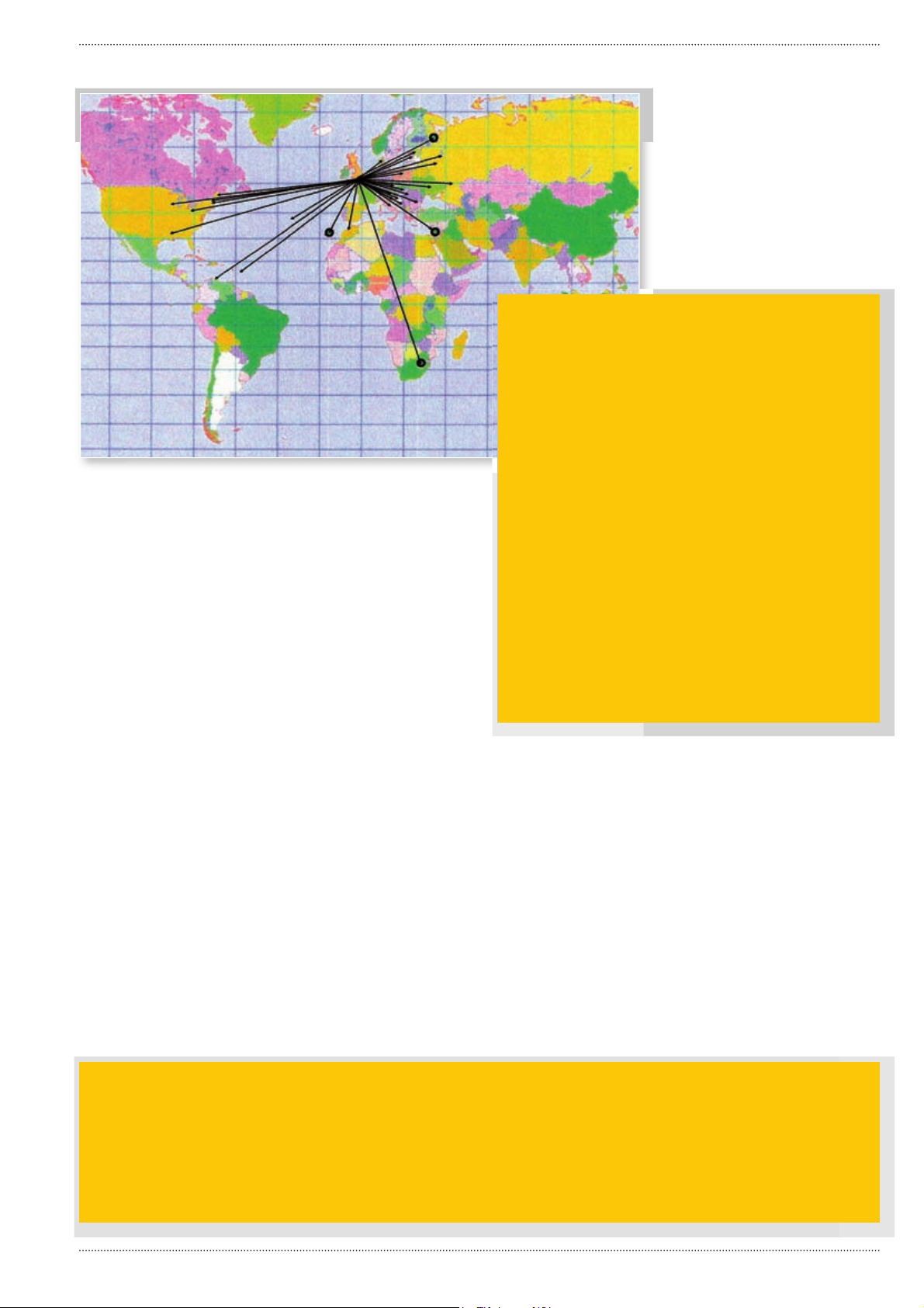
Fig. 4: This map shows the location of the
stations worked, using the Comet CHA-250BX,
when propagation conditions allowed. This
meant in one case working after midnight in a
freezing cold outdoor shack!
Product: The Comet CHA-250BX vertical antenna.
Company: (UK agents and distributors) Nevada.
Pros: The CHA-250BX has proved itself to be a good
antenna by its performance, and its actual v.s.w.r. across
the bands, with good quality feeder, meets the claimed
fi gures.
Because of these
problems I decided to
carry out a beacon search
(using the inrcedibly helpful
International Beacon
Project’s 18 beacon,
worldwide system, see
http://www.ncdxf.org/
beacon/BeaconSchedule.
html) on the offending
bands, 14 to 28MHz. And
where I’ve heard any
beacons, I’ve included them
on the results map, Fig. 4.
Please note that the lack of
results can’t be laid at the
foot of the antenna and we
all look forward to better
times in the not too distant
future. In general, when and
where propagation has been
good, so have the results!
Bands & Beacons
Heard
14.100MHz – 4U1UN (United
Nations building) S2, OH2B
(Finland) S1.
18.110MHz – CS3B
(Madeira Island) S8.
21.150MHz – CS3B
(Finland) S9.
24.930MHz – CS3B
(Madeira Island) S 8, ZS6DN
(South Africa) S1.
28.200MHz – Nothing
heard.
Note: even though the 18,
21 and 24MHz beacons were
of good strength, there were
no contacts to be made on
these bands. No contacts
were made on 50MHz but an
SWR of 1.5:1 was achieved.
A Good Antenna
The CHA-250BX has proved
itself to be a good antenna
by its performance, its
actual v.s.w.r. across the
bands, with good quality
feeder, meets the claimed
fi gures but variations can
be expected if anything
other than ‘Low loss’ feeder
is used. Other reasons can
reasonably be attributed
to local conditions or the
difference made by height.
I did some tests with the
antenna lower than the
height specifi ed (easy when
you can pump the mast
to intermediate heights)
Cons: Assembly really requires two people and plenty
of space.
Price: The CHA-250BX antenna costs £299.95 plus £10
P&P.
Suppliers: My thanks for the loan of the review unit go
to Nevada Radio, Unit 1, Fitzherbert Spur,
Farlington, Portsmouth, Hampshire PO6 1TT.
Tel: +44 (0) 23 9231 3090
Fax: +44 (0) 23 9231 3091.
E-mail: [email protected]
Website: http://www.nevadaradio.co.uk/
and the difference was
surprising. The matching
unit at the base of the fi rst
section is certainly effective
and there’s no need of an
a.t.u.
I agree with the suggestion
that the antenna is suitable
for small gardens but,
of course, no location is
identical to another and
new owners will need to be
resourceful during assembly.
The device is comparatively
light and mounting the
antenna to its mast may
appear easy enough – but a
momentary loss of balance
when it’s being raised can
occur leading to a variety of
nasty results. So get help for
the assembly and be safe.
Finally, I’m grateful to
Nevada for the opportunity
of reviewing the CHA-250BX,
it has given me hours of fun
doing what I like best of all
– operating on the bands.
The current diffi culties with
propagation conditions only
spur me on to ‘keep at it’
and the rewards are making
contacts despite those
diffi culties! ●
Mike Devereux G3SED replies: “Hi Rob! The review looks fair and factual. My own experience with this antenna has
found that it performed best for me on 20, 30 and 40 metres. When I tried this antenna against my 87ft Titanex Vertical
(with 140 132ft radials ) on 40 metres for example, I was truly amazed how close it came – only one S-point down.
Clearly it’s a winner on that band. I also had QSOs on 80 metres out to 200 miles during daylight, but my larger antenna
outperformed the Comet by over 3 S-points as you might expect. However, it allowed me to make QSOs at distance on
80 metres with a virtual nil footprint when compared to a 132ft dipole or the Titanex vertical with all those radials.Thanks
again for the review – a great job from Dave! Mike Devereux G3SED
Practical Wireless, March 2009
21
 Loading...