

Page 1

Defibrillation Monitor S Series
Service Manual
Shenzhen Comen Medical InstrumentsCo., Ltd.
Page 2

Defibrillator Monitor S Series Service Manual
Copyright
Shenzhen Comen Medical Instruments Co.,Ltd Version: 1.0
Product Name: Defibrillation Monitor
Model: S8
Statement
Shenzhen Comen Medical Instruments Co., Ltd. (belowComen is the copyright of this
non-publicly published maintenance manual and has the right to treat it as confidential
information. This Service Manual is a reference for the maintenance of Comen products.
Others have no right to disclose the contents of this manual to others.
This Service Manual contains proprietary information protected by copyright law.
Copyright, no part of this Service Manual may be photocopied, copied or translated into
another language without the prior written consent ofComen.
Comen is not liable for errors in the service manual or for incidental or
consequential damages resulting from the actual performance and use of this service
manual.Comen does not provide other parties with a franchise under the patent law.Comen
is not liable for legal consequences resulting from violations of patent law and any
third party rights.
The contents of the maintenance manual can be changed without notice.
Contact
Name: Shenzhen Comen Medical InstrumentsCo., Ltd. After-sales Service Department
Address:10-11F, Building 1A, 1A Building, Feiyada Clock Building, South Ring Road,
Matian Street, Guangming District, Shenzhen, China
Tel:0755-26431236
2
Page 3

Defibrillator Monitor S Series Service Manual
Fax:0755-26431232
Customer Service Phone:4007009488
Zip Code:518052
3
Page 4

Defibrillator Monitor S Series Service Manual
Directory
目录
Chapter 1 Safety ................................................................................................................................................ 6
1.1 Safety Information ............................................................................................................................. 6
1.2 Symbol Description ........................................................................................................................ 11
Chapter2 Warranty ......................................................................................................................................... 12
2.1 Warranty Terms .............................................................................................................................. 12
2.2 Exclusion of warranty ....................................................................................................................... 12
2.3 Maintenance procedures ................................................................................................................. 13
2.3.1 Fill in the Customer Complaint Form (SCF) ............................................................................ 14
2.3.2 Submit a customer complaint form and choose a solution ................................................... 14
2.3.3 RMA Form............................................................................................................................... 15
2.3.4 Return ..................................................................................................................................... 15
Chapter 3 Introduction to Principles ............................................................................................................... 17
................................................................................................................................................................. 17
3.1 Overview ......................................................................................................................................... 17
3.1.1 Introduction to Defibrillator ................................................................................................... 17
3.1.2 System Composition ............................................................................................................... 17
3.1.3 system structure diagram....................................................................................................... 19
3.2 Module Introduction ....................................................................................................................... 19
3.2.1 Main control board................................................................................................................. 19
3.2.2 AC power board ...................................................................................................................... 22
3.2.3 Keyboard ................................................................................................................................
22
3.2.4 DC power board .................................................................................................................. 24
3.2.5 Treatment module ................................................................................................................. 26
3.2.6 Side panel ............................................................................................................................... 32
3.2.7 NIBP module ........................................................................................................................... 33
3.2.8 IBP module ............................................................................................................................. 36
3.2.9 ECG Module ............................................................................................................................ 36
3.2.10 SPO2 Module ........................................................................................................................ 37
Chapter 4 Troubleshooting ............................................................................................................................. 41
................................................................................................................................................................. 41
4.1 Introduction ...................................................................................................................................... 41
4.2 Replaceable parts ........................................................................................................................... 41
4.3 Checking the monitor ....................................................................................................................... 41
4.4 Checking the software ...................................................................................................................... 41
4.5 Check the error message prompt ................................................................................................ 42
4.6 Troubleshooting.............................................................................................................................. 42
4.6.1 Electricity failure ..................................................................................................................... 42
4
Page 5

Defibrillator Monitor S Series Service Manual
4.6.2 Display failure ......................................................................................................................... 43
4.6.3 Battery failure ......................................................................................................................... 44
4.6.4 SPO2 failure ........................................................................................................................ 45
4.6.5 NIBP failure ........................................................................................................................ 46
4.6.6 TEMP Module failure ....................................................................................................... 47
4.6.7 Key failure ........................................................................................................................... 48
4.6.8 Software upgrade failure................................................................................................ 48
4.6.9 Technical alarm information ......................................................................................... 49
4.6.10 Electrode piece cable connection failure ................................................................ 49
4.6.11 Treatment Module failure ............................................................................................ 50
Chapter 5 software upgrade ........................................................................................................................... 52
................................................................................................................................................................. 52
5.1 Upgrade Preparation ..................................................................................................................... 52
5.2 System software upgrade .............................................................................................................. 52
Chapter 6 Performance Verification ............................................................................................................... 54
................................................................................................................................................................. 54
6.1 NIBP test ......................................................................................................................................... 54
6.1.1 NIBP Air leak test .................................................................................................................... 54
6.1.2 NIBP Pressure calibration ....................................................................................................... 55
6.2 IBP test ............................................................................................................................................ 56
6.3 ECG test .......................................................................................................................................... 57
6.4 SpO
test ......................................................................................................................................... 57
2
6.5 TEMP test........................................................................................................................................ 58
5
Page 6
Defibrillator Monitor S Series Service Manual
Chapter 1 Safety
1.1 Safety Information
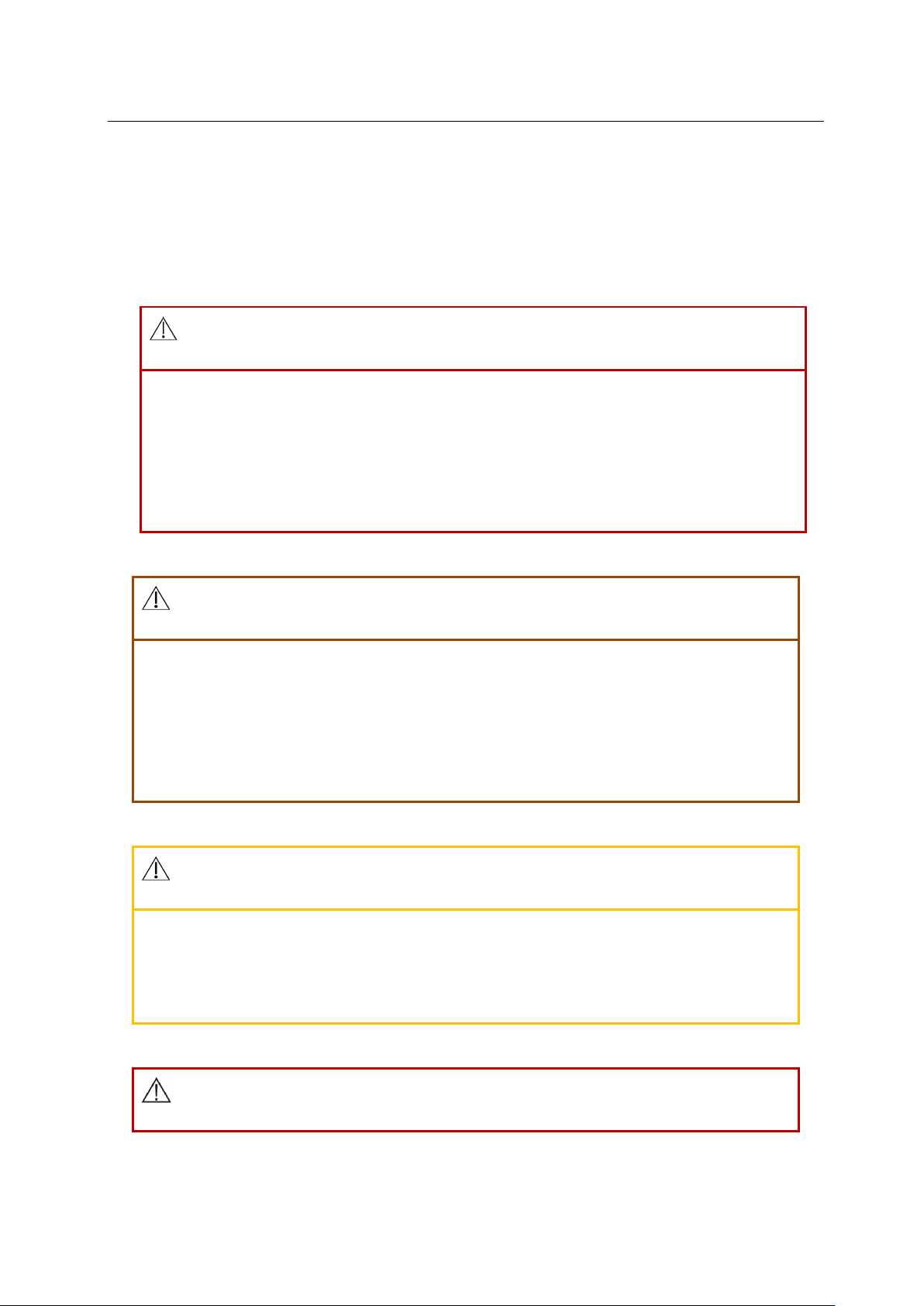
WARNING
● You may be prompted serious consequences, endanger the safety or
adverse events Case. Failure to follow the warning will result in death or
serious personal injury or property damage to the user or patient.
CAUTION
● Indicates a potentially hazardous or unsafe operation that, if not avoided,
could result in minor personal injury, product malfunction, damage, or
property damage, and may result in more serious injury in the future.
PAY ATTENTION TO
● important precautions, provide instructions or explanations to make
better use of this product.
WARNING
6
Page 7

Defibrillator Monitor S Series Service Manual
● This defibrillator is intended for use in clinical patient care and only allows
trained physicians and nurses to use the defibrillator.
● Before use, the user should check that the instrument and its accessories
are working properly and safely.
● The alarm volume and alarm upper and lower limits should be set for
different patients. When monitoring a patient, do not rely solely on the
audible alarm system to monitor the patient. If the alarm volume is set too
small or completely turned off, the alarm may be invalidated and the
patient's safety may be compromised. The most reliable method of patient
monitoring should be to pay close attention to the actual clinical condition
of the patient.
● This device can only be connected to a power outlet with protective
grounding. If the power socket is not connected to a grounding wire, do
not use the socket and use a rechargeable battery device to supply power.
● Do not open the case of the instrument to avoid possible electric shock
hazards. Any repairs and upgrades to the monitor must be performed by a
service person trained and authorized by Comen.
● When handling packaging materials, they should be disposed of in
accordance with local laws and regulations or the hospital's waste disposal
regulations. Packaging materials must be placed out of reach of children.
7
Page 8

Defibrillator Monitor S Series Service Manual
● Do not use the instrument in a location where flammable materials such as
anesthesia are placed to prevent an explosion or fire.
● Carefully install the power cord and various accessory cables to avoid
patient entanglement or suffocation, cable entanglement, or electrical
interference.
● Do not use a mobile phone near the monitor. The mobile phone generates
an excessive radiation field and interferes with the monitor's function.
● For patients with pacemakers, the heart rate monitor may pulse
pacemakers during cardiac arrest or arrhythmia. Do not rely solely on the
heart rate monitor alarm. Patients with pacemakers should be closely
monitored. Refer to the monitor's instruction manual for the ability of the
device to suppress the pacemaker.
● During defibrillation, the operator should not touch the patient, the table
and the instrument. Check that the function is normal before using these
cables again.
● The interconnecting device with the monitor should form an equipotential
body (the protective ground is effectively connected).
● When the monitor is shared with the electrosurgical device, the user
(doctor or nurse) should ensure the patient's safety.
8
Page 9

Defibrillator Monitor S Series Service Manual
● The physiological waveforms, physiological parameters and alarm
information displayed by the monitor are for medical reference only and
cannot be directly used as clinical treatment basis.
● Electromagnetic fields can affect the performance of the instrument, so
the use of other Instrumentsin the vicinity of the instrument must meet
the appropriate EMC requirements. For example, mobile phones, X-rays, or
MRI devices can all be sources of interference because they emit high-
intensity electromagnetic radiation.
● This is not a treatment device.
● After defibrillation, the recovery time of ECG is not more than 10s, and the
recovery time of other parameters is not more than 5s.
● To prevent burns to the patient when the monitor is used with a high
frequency surgical device, avoid any conductive connections between the
sensor and cable and the high frequency surgical device.
CAUTION
● To install or carry the instrument properly to prevent the instrument from
falling, colliding, being subjected to strong oscillations or other
mechanical external forces.
9
Page 10

Defibrillator Monitor S Series Service Manual
● Before the device is powered on, please confirm that the power supply
used meets the requirements of the instrument's nameplate label or the
power supply voltage and frequency specified in the instruction manual.
● When the instrument and accessories are about to expire, they must be
disposed of in accordance with relevant local laws and regulations or the
hospital's rules and regulations.
● Disposable accessories can only be used once, and repeated use can result
in performance degradation or cross-contamination.
● If the monitor will not be used for a long time, remove the battery and
keep it in a safe place.
● Defibrillation recovery time of less than 10s
PAY ATTENTION TO
● Install the instrument in a location that is easy to observe, operate, and
maintain.
● This instrument cannot be used at home.
● The instrument is limited to one patient at a time.
● The life of this monitor is 5 years.
10
Page 11
Defibrillator Monitor S Series Service Manual
measuring instrument type
manufacturing measuring
network connection
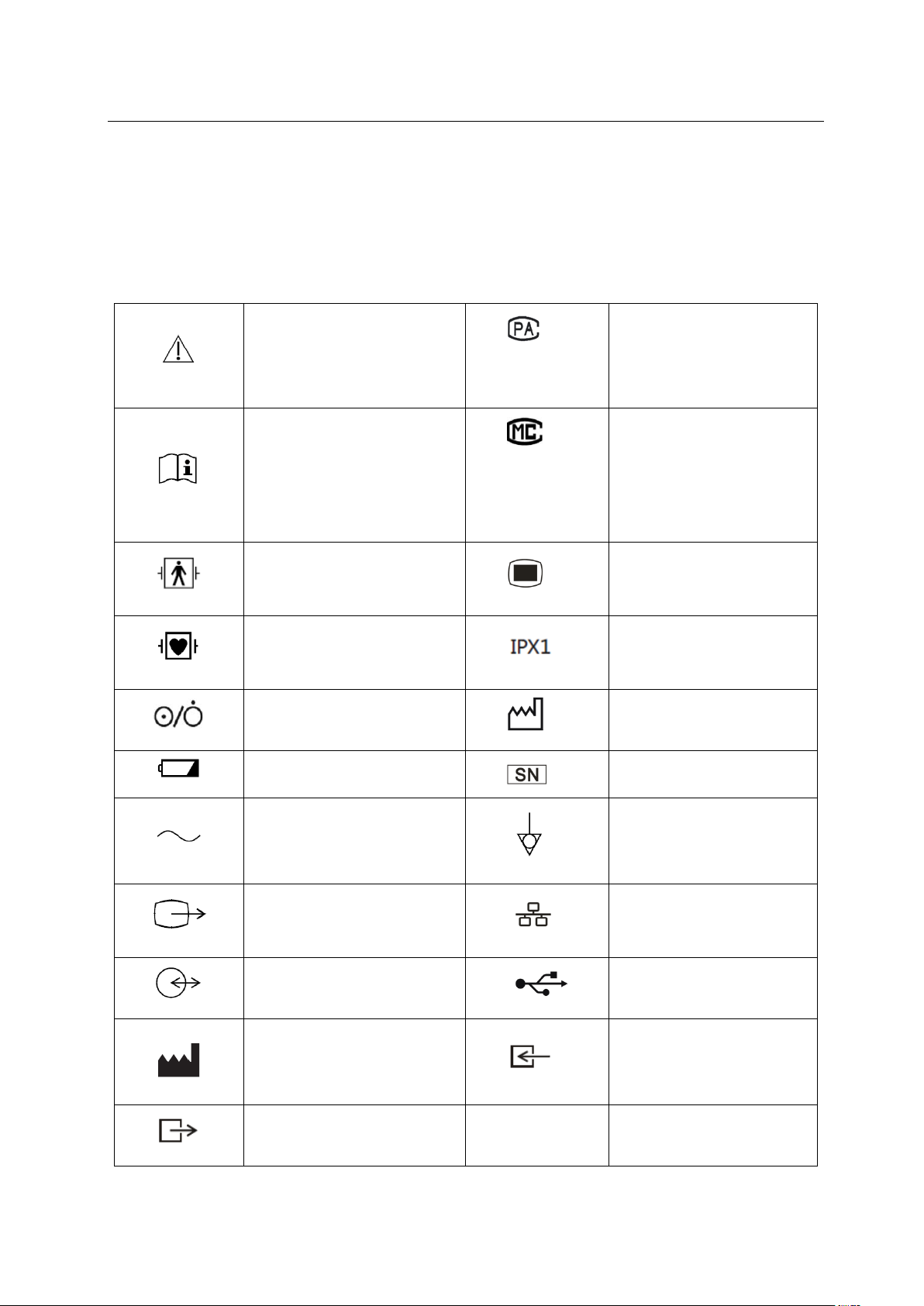
1.2 Symbol Description
(1) Instrument Symbol
Note!
approval mark and number
2015R124-44
refer to the operation manual
Guangdong
00000700
BF type application part, with
anti-defibrillation function
CF type application part, with
anti-defibrillation function
open, shutdown Key
use battery work light
instrument license mark and
number
main menu
waterproof level
production date mark
sequence number mark
AC power indicator light
VGA interface
multi-function interface
manufacturer
output port
table 1
11
equipotential symbol
symbol
USB interface
input port
Page 12
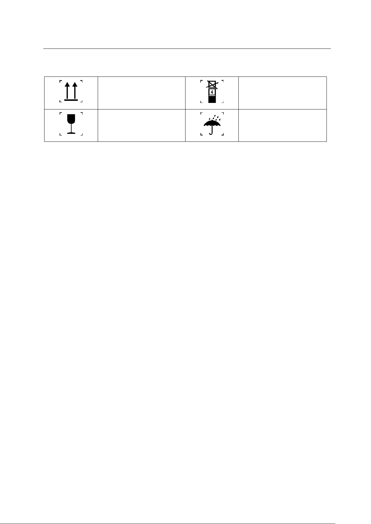
(2) packaging symbol
Defibrillator Monitor S Series Service Manual
up
fragile goods
stacking layer limit
rainproof
gauge2
Chapter2 Warranty
2.1 Warranty Terms
Comen provides a 24 month (host) warranty or a 6 month (accessory) warranty for all licensed products,
starting with the customer's purchase date. If your product is determined to be defective and promptly
notified to us during the warranty period, Comen will repair the product or replace it with a new product or
accessory.
2.2 Exclusion of warranty
The Comen warranty will not apply to the following:
Unreasonable use or damage caused by man
Damage caused by unstable voltage or super normal range voltage
Damage caused by irresistible factors, such as fires and earthquakes
Damage caused by unreasonable operation or repair by an unauthorized maintenance organization or
individual
12
Page 13
Defibrillator Monitor S Series Service Manual
Repair request
Instrument collection
Instrument
status
Return to customer
Inspection / repair
testing
Failed
qualified
Damage caused by attachments that are not approved by Comen.
The product serial number is not clear.
Other damage caused by the instrument or the component itself.
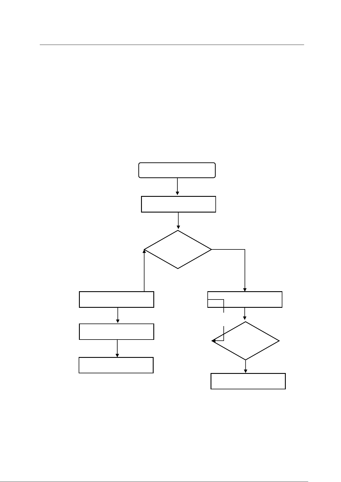
2.3 Maintenance procedures
No need to
Need to be
Apply for accessories
Office maintenance
Product
Return to office/client
figure 1
13
Page 14
Defibrillator Monitor S Series Service Manual
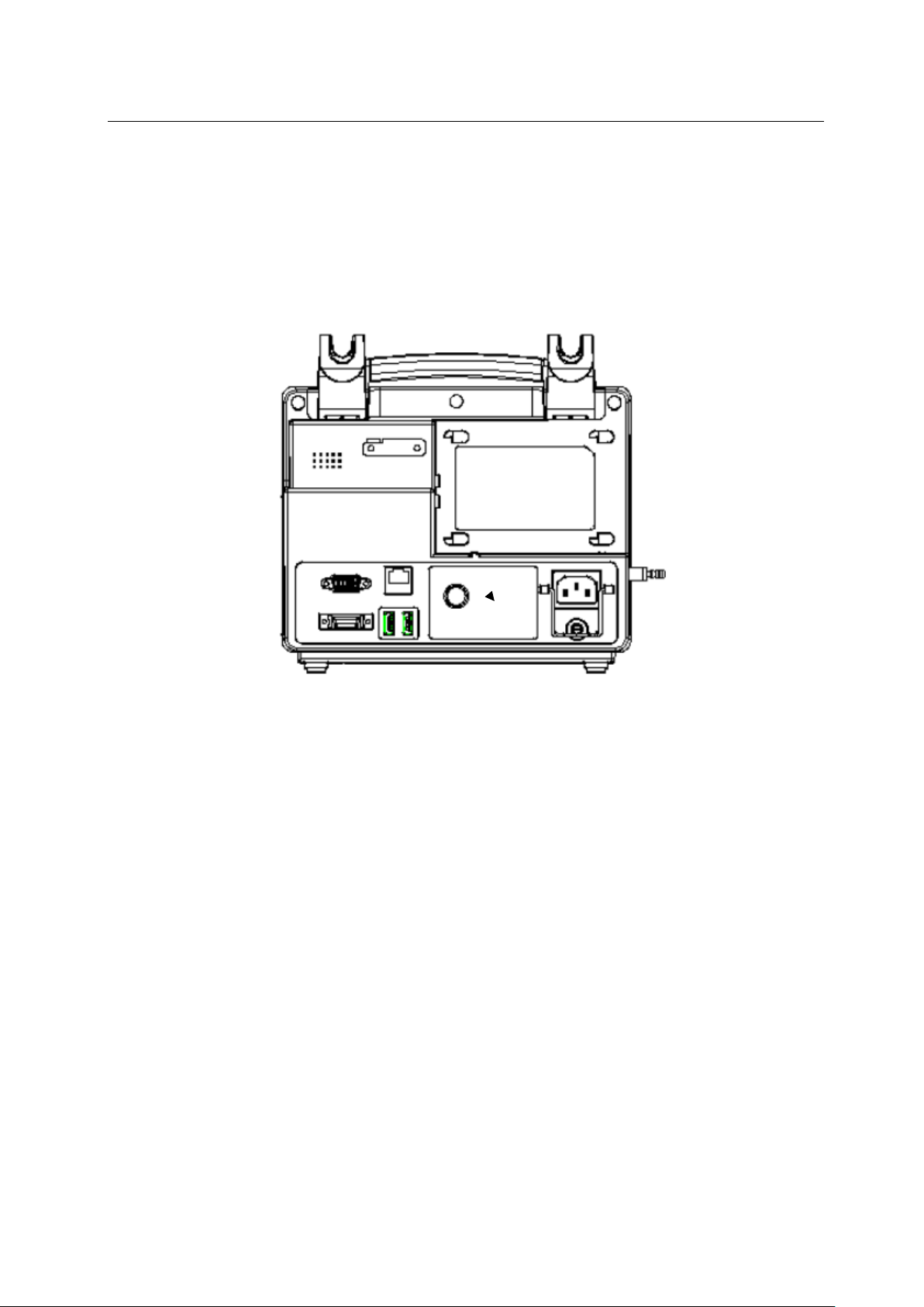
Serial number
(SN) see this
2.3.1 Fill in the Customer Complaint Form (SCF)
Fill in the customer complaint form in detail: model number, serial number (SN) and problem description.
Without this information, Comen will not be obliged to accept this complaint. Customers can apply for a
complaint form from Comen's after-sales department if needed.
nameplate
Figure 1
2.3.2
Submit a customer complaint form and choose a solution
Once the after-sales department receives the customer complaint form, the engineer will provide the
customer solution within three days. And deal with it according to the following two situations:
Warranty period:
There are two options:
1) After receiving the Return Authorization Form (RMA) from the After-sales Department, the customer
can return the defective part and inform the delivery number. We will send a new part with the loading
invoice to your address as soon as possible.
2) You can also send the signed statement to us by mail or fax. The statement has the legal effect to ensure
that the customer or the end customer will send the faulty part to Comen in time. In this case, we will
send the replacement parts and loading invoices in a timely manner.
14
Page 15
Defibrillator Monitor S Series Service Manual
Caution
Once the customer complaint form has been confirmed, Comen engineers will provide you with
a return authorization and declaration form.
The customer is responsible for shipping, insurance and custom s fees for the shipment of the
product to Comen.
The warranty period has expired:
After receiving the return authorization form, the customer will send the faulty part to Comen. Our
engineers will analyze the faulty parts and negotiate with the customer to repair or replace the faulty parts.
After the maintenance fee has been paid, we will send out new replacement parts as soon as possible.
Caution
The customer is responsible for all costs (including freight, insurance and customs fees) during
the transportation process.
2.3.3 RMA Form
Before returning the goods, the customer will receive an RMA Form (Return Authorization Form)
provided by our after-sales department, which includes the RMA number, a brief description of the returned
parts and shipping instructions. When shipping, please indicate the RMA number on the box.
Caution
In the absence of a notice to the Comen after-sales department, we will not be obligated to process
returns from the terminal or customer. And the shipper is responsible for all possible expenses.
2.3.4 Return
Please follow the steps below
When disassembling the instrument, use an anti-static requirements. Do not touch the instrument
directly with your hands.
Pack the parts carefully before shipping.
15
Page 16

Defibrillator Monitor S Series Service Manual
Please indicate the RMA number on the package.
When describing the product, please use the “*** sample” format to reflect the total value on the
invoice and mark “sample, no commercial value”. .
Before returning, please check with Comen (for example: total amount, address and other necessary
information on the invoice).
After receiving confirmation from Comen, please return the faulty part.
16
Page 17
Chapter 3 Introduction to Principles
3.1 Overview
Defibrillator Monitor S Series Service Manual
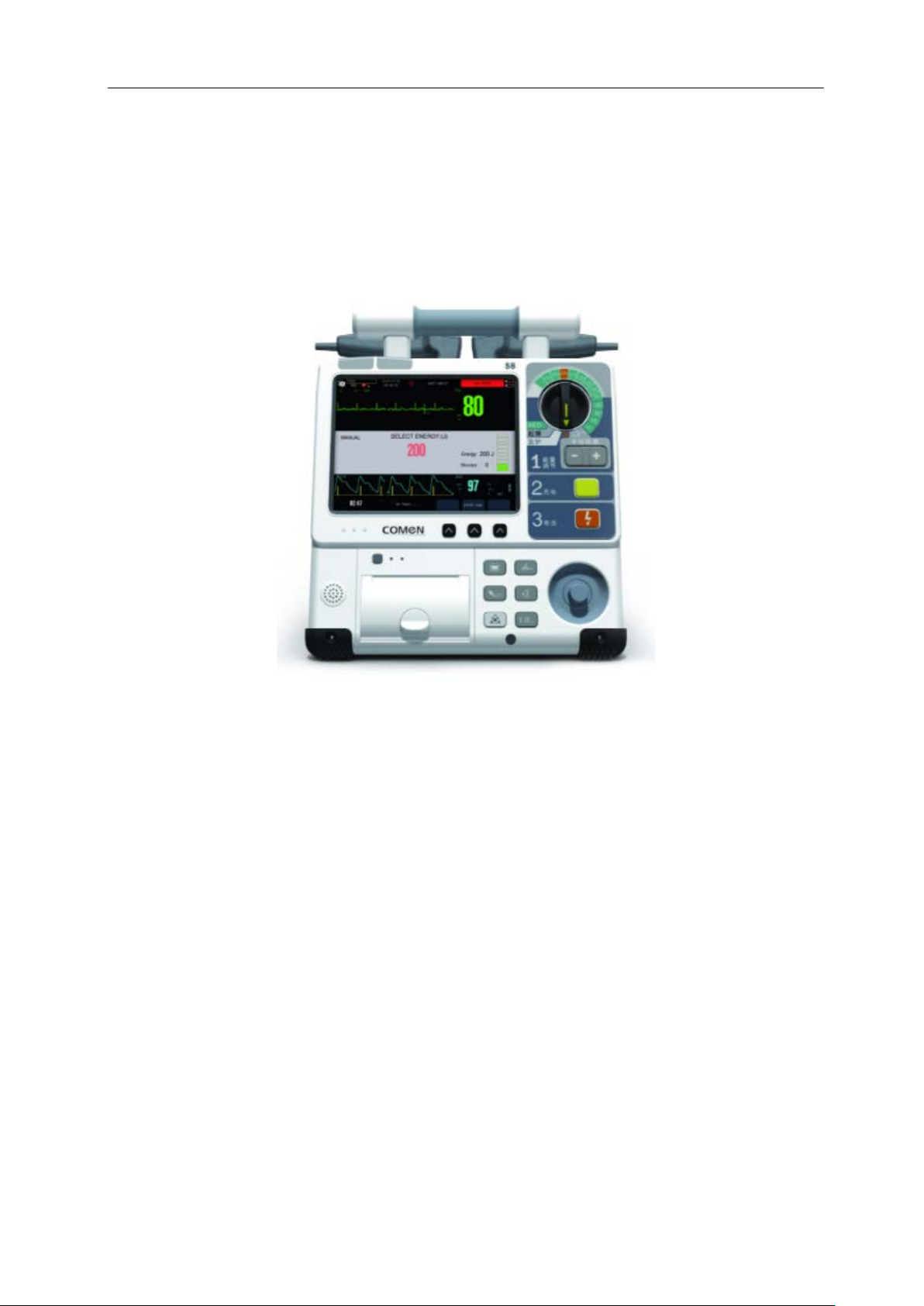
3.1.1 Introduction to Defibrillator
S-Series defibrillation monitors can monitor ECG, RESP, SpO2, NIBP, Invasive Blood Pressure (IBP), Carbon
Dioxide (CO2), Body Temperature (TEMP), etc. Vital sign parameters. This product is suitable for manual
defibrillation, AED defibrillation, pacing and vital signs monitoring.
3.1.2 System Composition
The defibrillator monitor consists of a host, a battery, a defibrillation electrode plate (defibrillation
external electrode plate, and a defibrillation internal electrode plate) and corresponding functional
accessories. Mainly achieve the following functions:
1. Defibrillation monitor defibrillation release energy accuracy;
2. Pace frequency accuracy;
3. Pace current accuracy;
17
Page 18

Defibrillator Monitor S Series Service Manual
4. Heart rate detection accuracy;
5. Respiratory measurement accuracy:
6. Body temperature measurement error;
7. Non-invasive blood pressure measurement accuracy:
8. Invasive blood pressure measurement accuracy;
9. Blood oxygen saturation measurement accuracy;
10. Pulse rate measurement accuracy.
CO2 measurement accuracy:
18
Page 19
Defibrillator Monitor S Series Service Manual
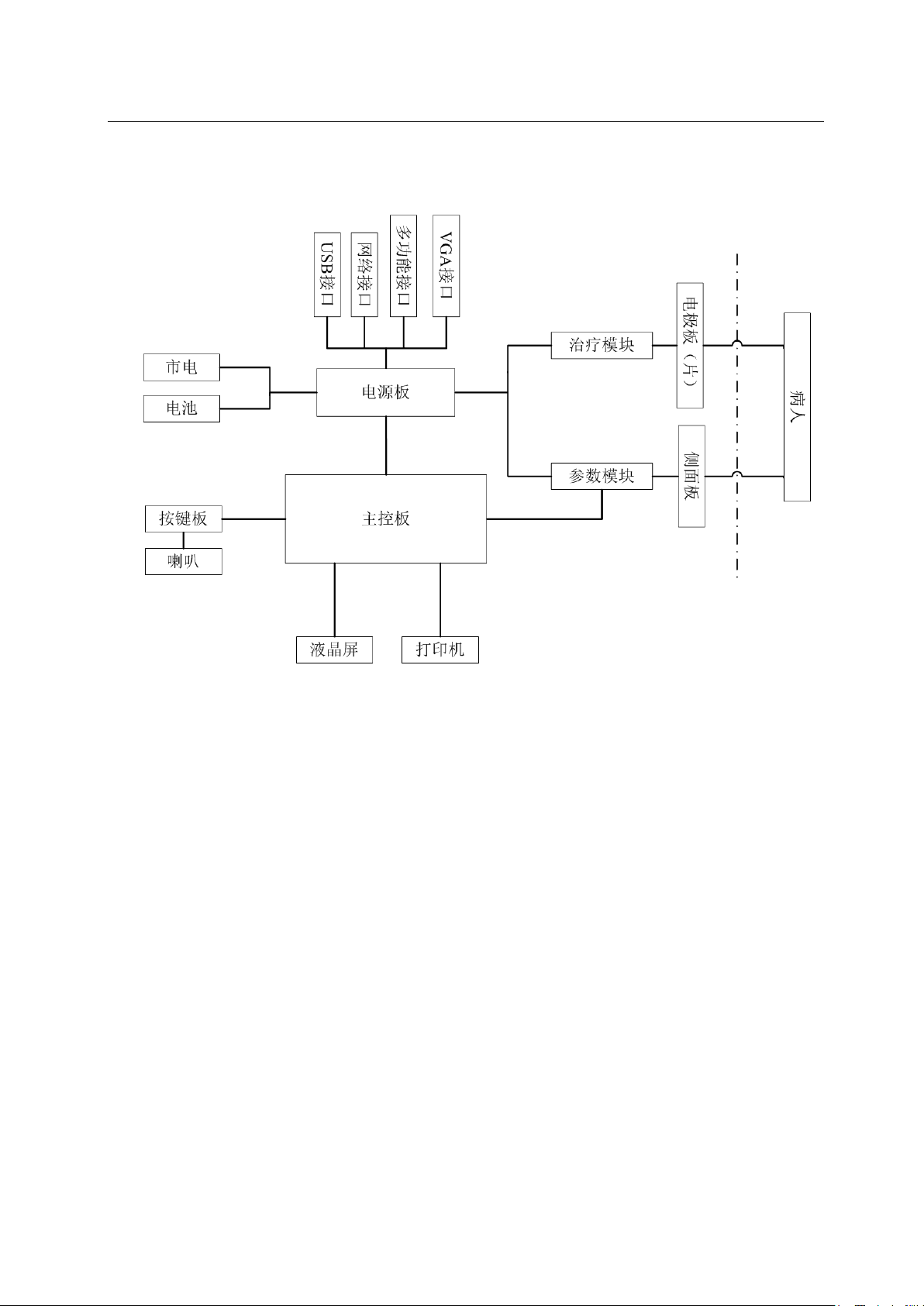
3.1.3 system structure diagram
Figure 3
3.2
3.2.1 Main control board
Module Introduction
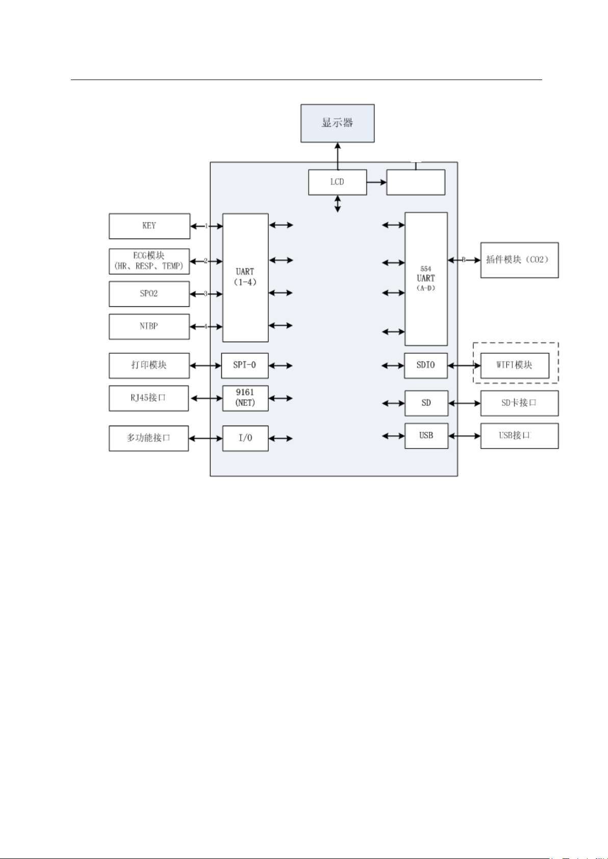
The main board is the core of the entire monitor, responsible for processing: input and output
control, data storage and processing, display, system control, communication management and more.
Main control board functional block diagram:
19
Page 20
Defibrillator Monitor S Series Service Manual
Figure 2
20
Page 21
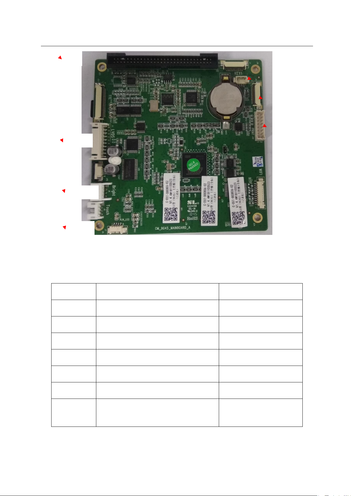
5V, 12V, 18V
P1
J33
Defibrillator Monitor S Series Service Manual
J3
J4
J32
J8
J7
Figure 3
socket description
working voltage
J3 4pin, connection button board /
J4 22pin, connection button board 5V
J7 4pin, connection alarm light 5V
J8 4pin, connect LCD screen /
J32 16pin, then the printer 18V60pin,
J33 5V,connected to AC-DC power board
connected to the LCD screen 5V, 12V, 3.3V
P1 (8000F
table 1
21
Page 22
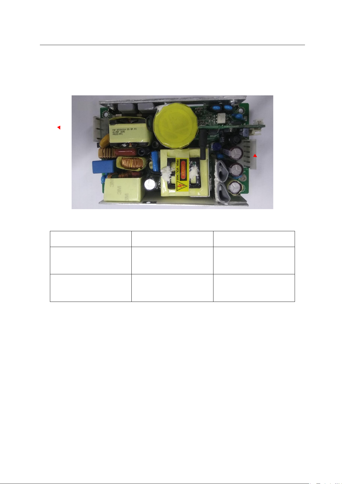
5pin, connect AC power
DC power
3.2.2 AC power board
P1
Defibrillator Monitor S Series Service Manual
P2
Figure 6
socket description
P1
supply
P2 6pin, connect AC-
supply board
table 2
working voltage
100-240V AC
18V
3.2.3 Keyboard
The keypad is located in the front of the monitor. Through the MCU processing on the keypad, the
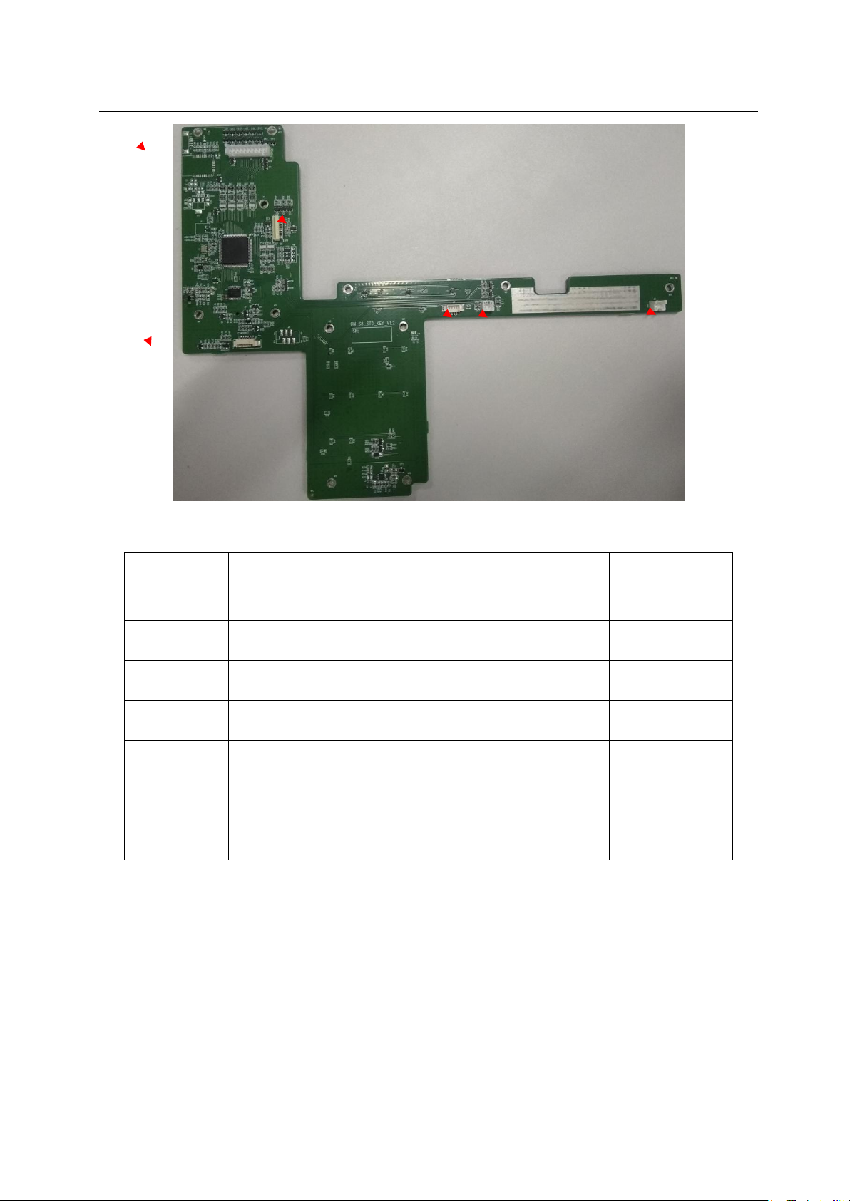
signal can be transmitted to the main board, as well as the display of the power indicator, AC indicator and
charging indicator.
22
Page 23
Defibrillator Monitor S Series Service Manual
J10
J13
J8
J9
J14
J5
Figure 7
socket description
J5 20pin, connection dial board /
J8 4pin, connect main control board /
J9 2pin, connect speaker /
J10 22pin, connect main control board 5V
J13 2pin, printer keypad /
J14 6pin, connected to the shuttle board /
working
voltage
Table 3
23
Page 24
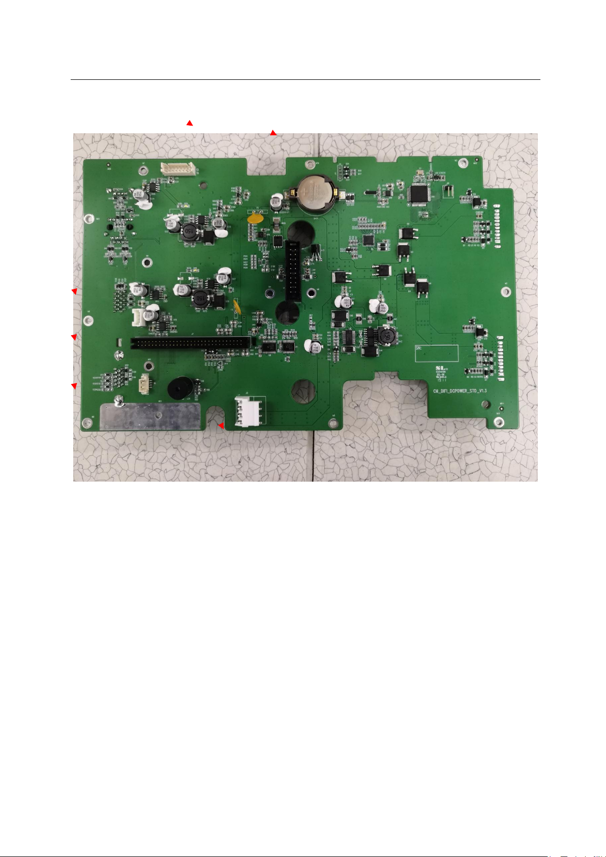
Defibrillator Monitor S Series Service Manual
J8
J4
J3
J9
J7
J6
3.2.4 DC power board
Figure 8
24
Page 25
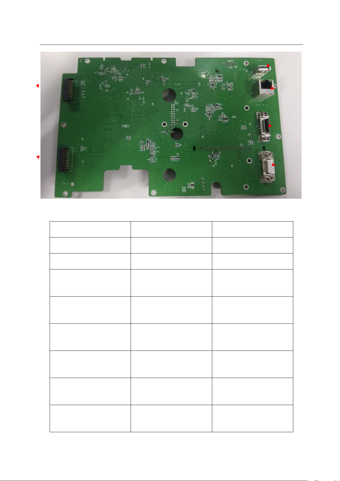
Defibrillator Monitor S Series Service Manual
4pin AC switching power
20pin, connected to the
60pin, connected to the
16pin, connected
4pin, connected side
function
J13
J12
J14
J15
J2
J1
Figure 9
socket description
working voltage
J1 10pin, battery A /
J2 10pin, battery B /
J3
18V
supply
J4
5V, 12V, VBUS
treatment module
J7
3.3V, 5V, 12V, V_PRINT
main control board
J8
5V, 12V
J9
J12 20pin, Multi-
parameter module
5V
panel
5V
interface
25
Page 26
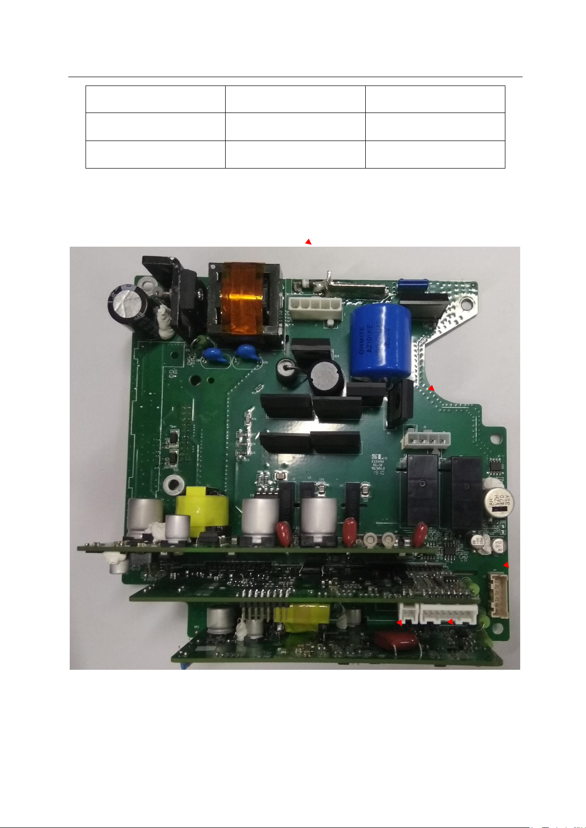
Defibrillator Monitor S Series Service Manual
J1
J13
J2
J4
J8
J13 15pin, VGA interface /
J14 16pin, network port /
J15 6pin, USB port 5V
table 4
3.2.5 Treatment module
Figure 10
26
Page 27
Defibrillator Monitor S Series Service Manual
J26
J25
J12
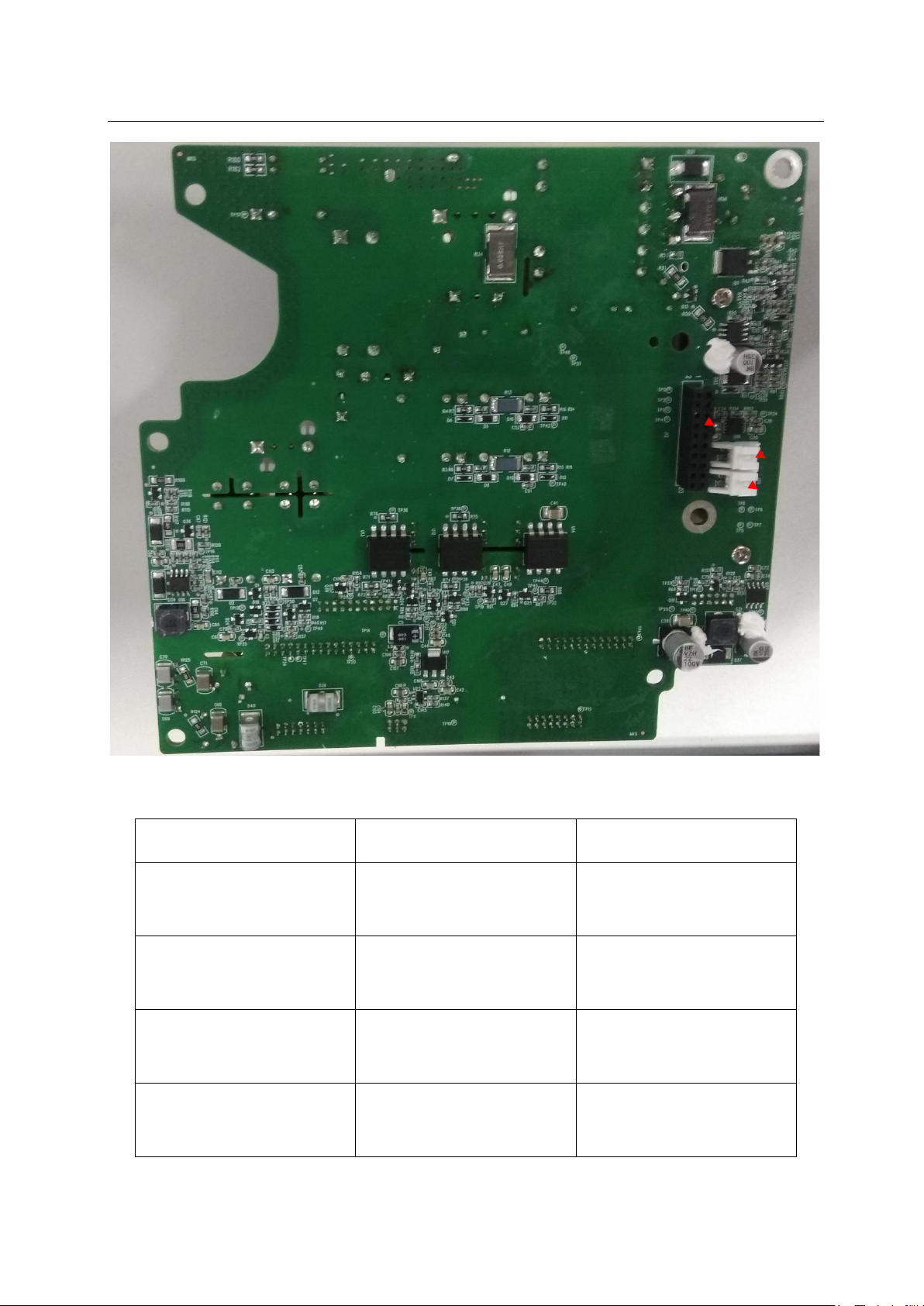
Figure 11
socket description working voltage
5pin,connection Charging
J1
/
capacitor
4pin,connect the internal
J2
5V
cable
2pin,connect the micro
J4
/
switch
8pin,connect the internal
J8
/
cable
27
Page 28
Defibrillator Monitor S Series Service Manual
J3
J1
J12
20pin,connect the power
supply board
6pin,connect the internal
J13
cable
J25
J26
2pin,Connect the cooling fan
2pin,connect the cooling fan
table 5
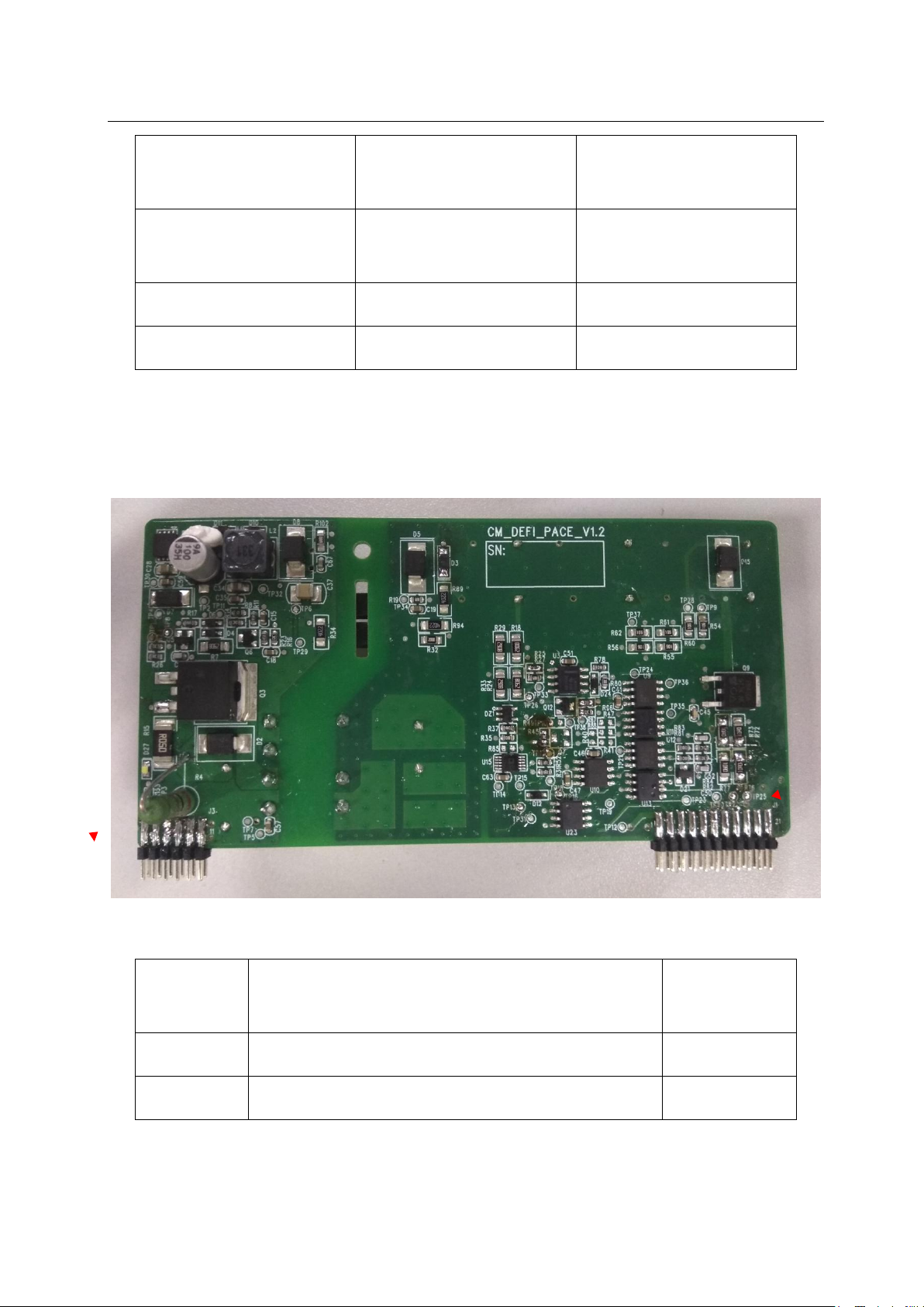
3.2.5.1 Treatment module pacing board
5V, 12V
/
12V
12V
Figure 12
Socket
description
working
voltage
J3 12pin, docking high voltage board J11 /
J1 22pin, docking high voltage board J9 /
28
Page 29
Defibrillator Monitor S Series Service Manual
J4
J8
J7
J23
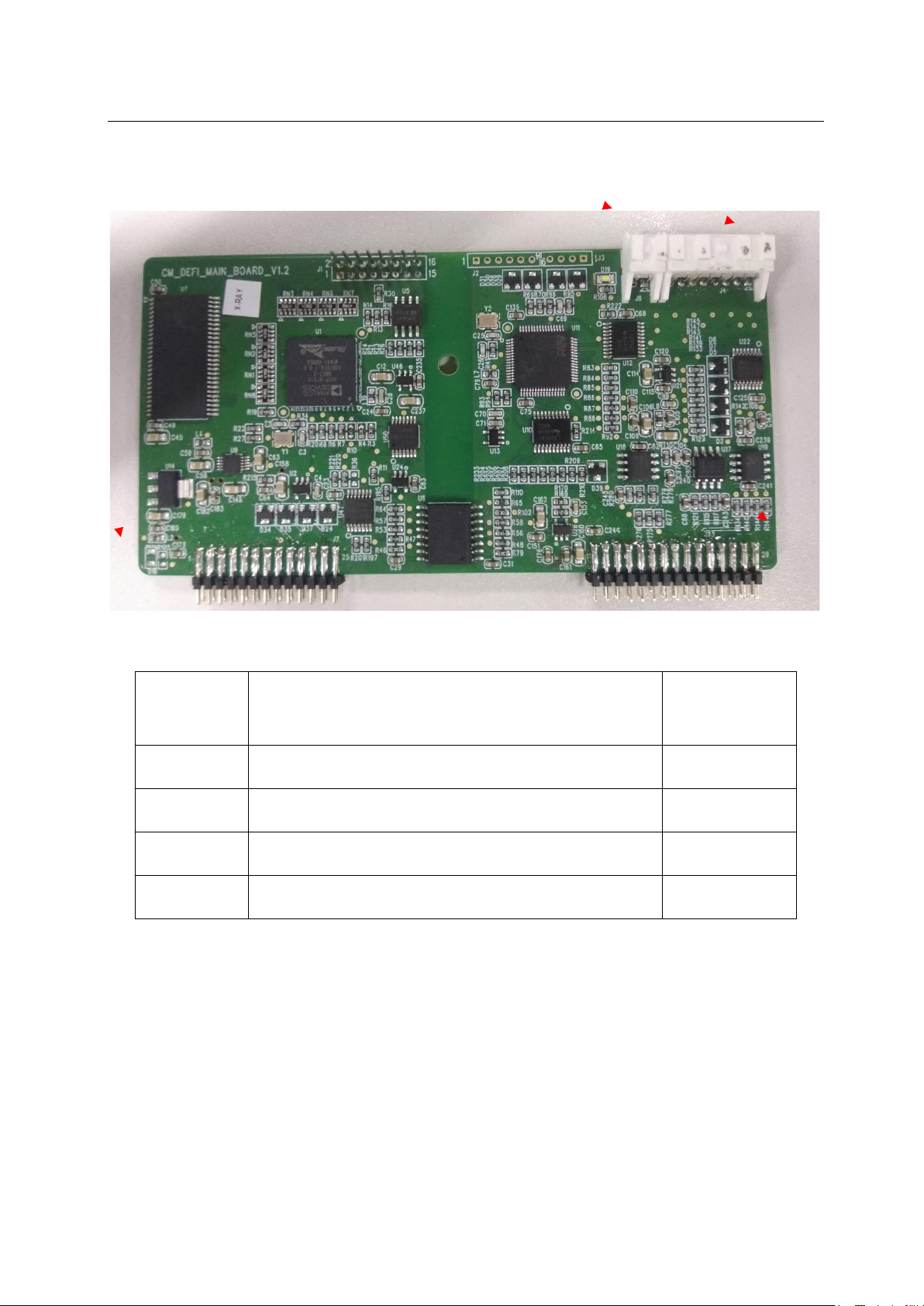
3.2.5.2 Treatment module main control board
Figure 13
socket
description
working
voltage
J4 8pin, connecting machine inside /
J7 26pin, docking high voltage Board J8 /
J8 2pin, connected micro switch /
J23 30pin, docking high voltage board J9 /
29
Page 30
Defibrillator Monitor S Series Service Manual
J3
J7
J2
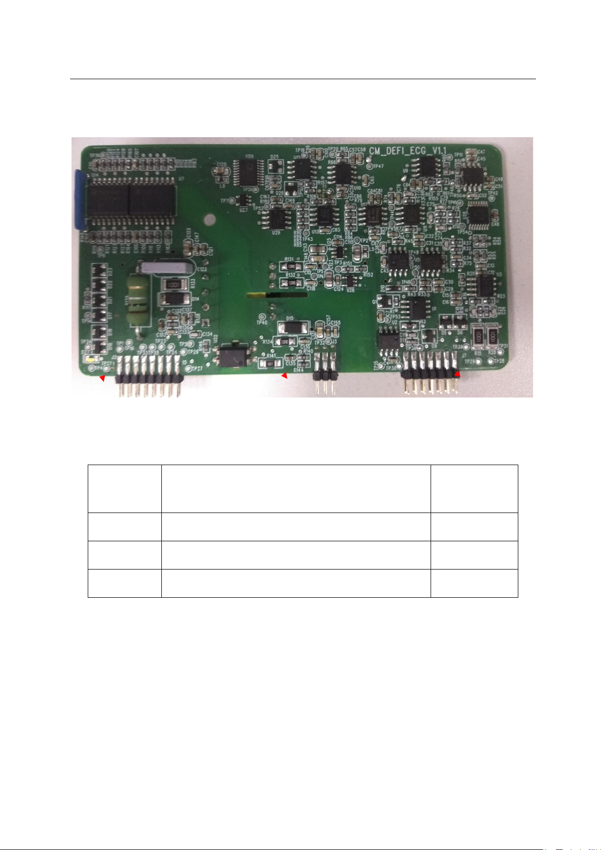
3.2.5.3 Treatment module ECG board
Figure 14
socket
description
working
voltage
J2 16pin, docking high voltage board J6 /
J3 6pin, docking high voltage board J7 /
J7 14pin, docking high voltage board J5 /
30
Page 31
Defibrillator Monitor S Series Service Manual
J1
J6
J8
J11
J5
J13
J9
J10
J2
J7
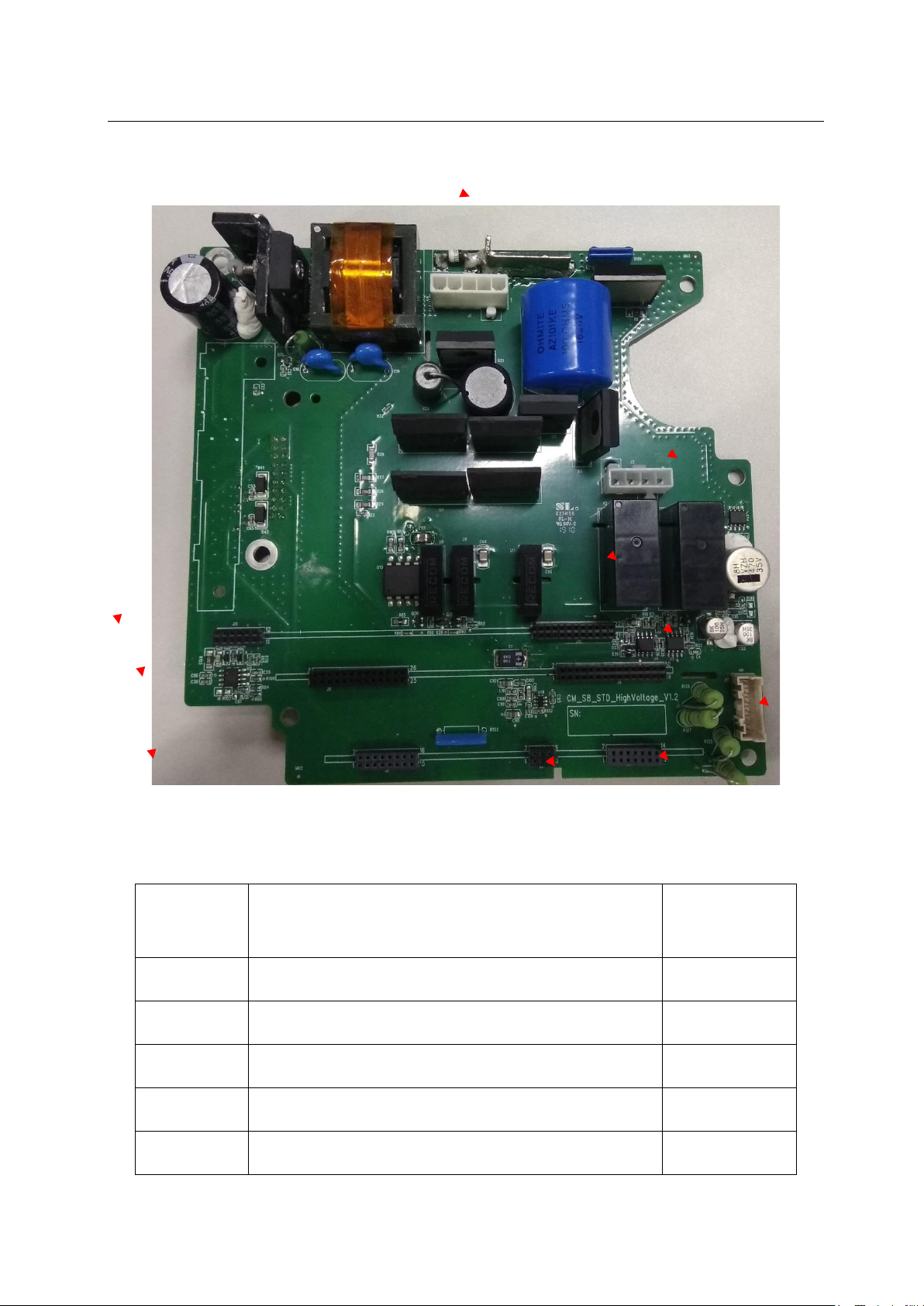
3.2.5.3 Treatment module high pressure plate
Figure 15
socket description
J1 5pin, charging capacitor socket /
J2 4pin, connecting machine inside /
J5 14pin, Treatment ECG socket /
J6 16pin, treatment ECG socket /
J7 8pin, treatment ECG socket /
31
working
voltage
Page 32
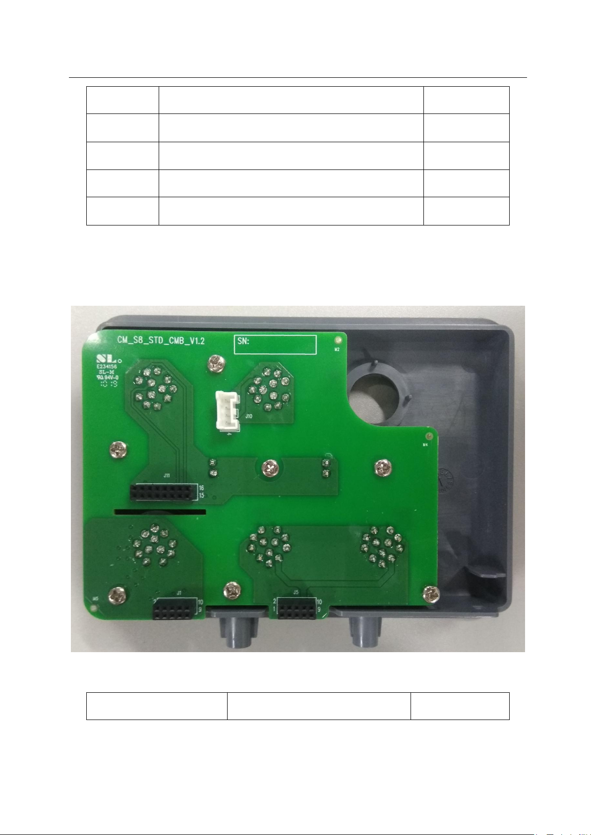
Defibrillator Monitor S Series Service Manual
J8 26pin, treatment main control panel socket /
J9 30pin, treatment main control panel socket /
J10 22pin, treatment pacing plate socket /
J11 12pin, treatment pacing board socket /
J13 6pin, connecting machine inside /
3.2.6 Side panel
Figure 16
socket description
32
working voltage
Page 33
Defibrillator Monitor S Series Service Manual
10pin, SPO2 socket docking
10pin, IBP socket docking
Socket docking power
16pin, ECG, TEMP parameter module
CPU
NIBP通讯接口
EEPROM
COM
LDO POWER
NIBP board
CUFFSensor
12V
Motor and Air valve
J6
J1
/
parameter module
J5
/
parameter module
J10 4pin, CO2
5V
supply
J11
/
docking socket
table 6
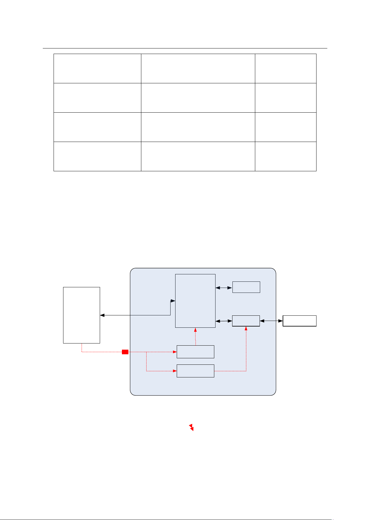
3.2.7 NIBP module
The NIBP module is responsible for blood pressure pumping, pressure detection, and
overvoltage protection.
NIBP module function box Figure:
J7
J4
Figure 17
J3
33
Page 34
J2 J5
J10
Defibrillator Monitor S Series Service Manual
J11
J1
J9
J8
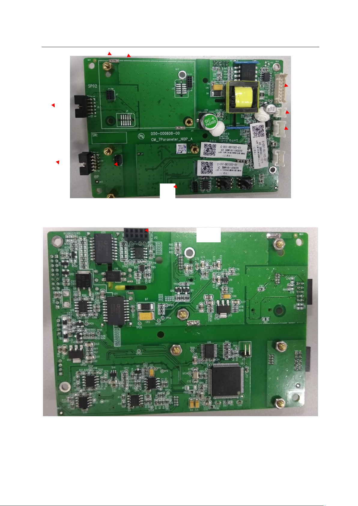
Figure 18
J12
Figure 18
34
Page 35

Defibrillator Monitor S Series Service Manual
10pin, docking simulation /
10pin, docking
14pin, connecting seven ginseng
Socket
description
working voltage
J1 2pin, connecting air pump 12V
J2 4pin, connecting valve 12V
J3 10pin, docking Masimo oximeter 3.3V
J4 10pin, docking Masimo oximeter /
J5 10pin, docking side panel 3.3V
J6
3.3V
Digital/Nellcor oximeter
J7
/
analog/digital/Nellcor oximeter
J8 10pin, docking IBP board 5V
J9 10pin, docking IBP board 5V
J10 10pin, docking side panel /
J11
5V, 12V
blood pressure board
J12 10pin, connected to ECG board /
table 7
35
Page 36
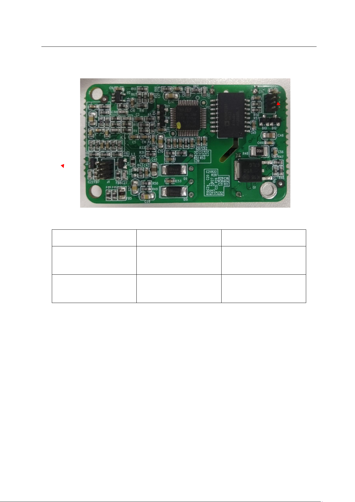
3.2.8 IBP module
J2
J1
Defibrillator Monitor S Series Service Manual
socket description working voltage
J1
J2
3.2.9 ECG Module
Figure19
connection IBS socket IBP
5V
socket J8/J9
connection IBS socket IBP
5V
socket J8/J9
table 8
36
Page 37
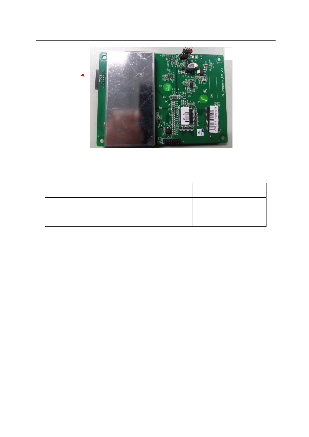
Defibrillator Monitor S Series Service Manual
J3
J2
Figure 20
Socket Description Operating Voltage
J2 Connection NIBP Module 6.6V, 5V, 3.3V
J3 Connection Side Panel 5V
table9
3.2.10 SPO2 Module
Three Blood Oxygen Modules: COMEN Blood Oxygen, Masimo Blood Oxygen and Nellcor
Blood Oxygen
The oximeter is mainly used for the collection of blood oxygen signals,
amplification simulation, and conversion and processing of electrical signals.
During the monitoring process, the pulse amplitude of the optical signal also
changes. By calculation, blood oxygen parameters, pulse rate signals and volume waves
can be obtained. This data is then transferred to the main board via a special
communication protocol.
37
Page 38
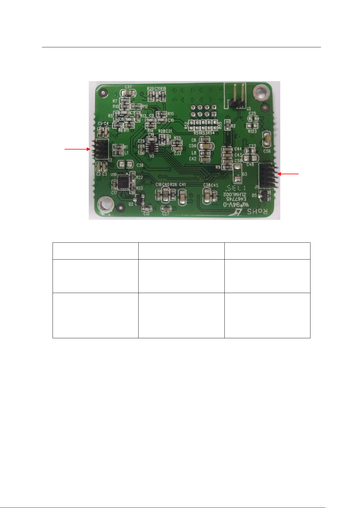
Defibrillator Monitor S Series Service Manual
Measurement signal input
3.2.10.1 COMEN SPO2 Module
J2
J1
Figure 21
serial number
description
J1 2*5pin,SPO2Module
Communication Interface
J2 2*4pin,SPO2Module
interface
table 10
working voltage
3.3V
/
38
Page 39
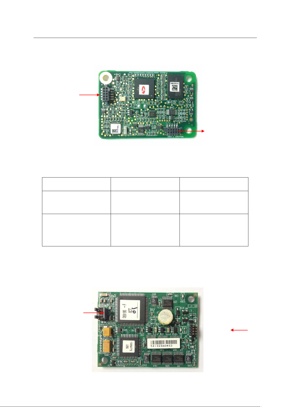
Defibrillator Monitor S Series Service Manual
SPO2Module
SPO2Module
Measurement signal input
3.2.10.2 MASIMO SPO2Module
J1
J2
Figure 22
serial number
J1 2*5pin ,
J2 2*5pin ,
description
Communication Interface
interface
table 11
3.2.10.3 NELLCOR SPO2 Module
working voltage
3.3V
/
J1
J2
39
Page 40

Defibrillator Monitor S Series Service Manual
SPO2Module
Measurement signal input
Figure
serial number
description
J1 2*5pin,SPO2Module
Communication Interface
J2 2*4pin ,
interface
table 12
working voltage
3.3V
/
40
Page 41

Defibrillator Monitor S Series Service Manual
Chapter 4 Troubleshooting
4.1 Introduction
In this chapter, some common faults and troubleshooting methods for defibrillation monitors are
introduced. If your fault is not listed, please contact Comen's after-sales service department.
4.2 Replaceable parts
The main components and components in the monitor PCB are replaceable. If a separate PCB board is
faulty, follow the instructions for “Assemble and Disassemble”, replace it with a brand new PCB board, and
finally check if the monitor's performance is restored. If the problem persists, reinstall the faulty PCB and
continue troubleshooting according to the instructions in this section. You can also send the PCB back to
Comen for repair.
4.3 Checking the monitor
In troubleshooting, some require you to check the hardware version of the monitor and the status of
the instrument.
4.4 Checking the software
In troubleshooting, some require the customer to check the monitor's configuration and software
version.
View the system configuration and software version: After booting the self-test (heep beep), press
Main Menu -> Monitor Maintenance -> Monitor Information to view the system running time, system
software version and hardware version.
41
Page 42
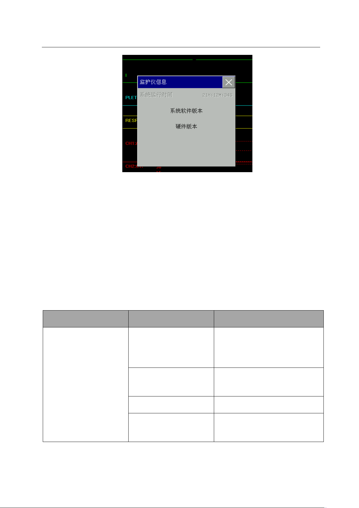
Defibrillator Monitor S Series Service Manual
The monitor does not
Check if the dial cable is
Check the connection of the
Boot button board is
Replace the power button or
Figure 4
4.5
message, remove the alarm first according to the instruction manual.
4.6 Troubleshooting
Check the error message prompt
Check the error message prompt area of the monitor before troubleshooting. If there is an error
4.6.1 Electricity failure
phenomenon reason measure
Dish is damaged
The power cable is not
damaged or not connected. Replace
the dial.
start
connected properly.
battery is low Check battery level
damaged
42
power cord
keypad
Page 43

Defibrillator Monitor S Series Service Manual
to the main control board, and
control board. Check whether the
AC power module is
The monitor works
board to the main control board
The monitor works
normally, the display is
Broken wiring or poor
Check the cable from the keypad
Poor wiring contact
The keypad is damaged Replace the keypad
damaged
Power board damage Replace the power board
Main board damage Replace the main board
table 1
4.6.2 Display failure
phenomenon reason measure
connect the power cable to the main
wiring is damaged.
Replace the AC power module
normally and the display is
blank.
lacking color or the screen is
Check the LCD cable to the main
control board cable, check the power
Poor contact or damage to the
wiring
Display module damage Replace the display module
main board damage Replace the main board
keyboard damage Replace the keyboard
contact
cable, check the button board to the
main control board cable; check the
wiring and interface for damage.
Check the wiring of the keypad
and the main board; check the LED
Screen and main control board
wiring
main board damage Replace the main board
43
Page 44

Defibrillator Monitor S Series Service Manual
Display module
Broken wiring or poor
Display module
Uneven display
Broken wiring or poor
Display module
cannot be
Reinsert the battery; models with dual
battery can be charged for another channel;
cannot be
Use the universal table to measure the
Display blinks
brightness
damage
Replace the display module
Check the wiring of the keypad
and the main board; check the LED
contact
screen and button board wiring
keyboard damage Replace the keyboard
main board damage Replace the main board
Replace the display module
damage
Check the wiring of the keypad
and the main board; check the LED
contact
screen and button board wiring
Replace the display module
damage
table 2
4.6.3 Battery failure
phenomenon reason measure
Battery
charged
Battery
powered
Poor or damaged battery
and machine connection
replace the battery
Power board damage Replace the power board
voltage and observe whether the voltage range is
normal. For specific voltage values, please consult
Battery damage
Comen after-sales personnel; reinsert the battery;
models with dual batteries can be exchanged for
another battery channel; replace the battery
44
Page 45

Power board damage Replace the power board
SPO2Module has poor
contact with the side
Check the cable or socket of the
Seven ginseng blood
pressure plate is in poor
parameter blood pressure plate
Probe does not match
4.6.4 SPO2 failure
phenomen
reason measure
on
SPO2 probe is damaged Replace the SPO2 probe
Defibrillator Monitor S Series Service Manual
table 3
No
SPO2
value
interface
contact with SPO2Module
SPO2 Module is
damaged
SPO2Module type is not
set (default analog SPO2)
SPO2Module and the side interface, and
check
New connection
Check if the connection between the
seven-
and the SPO2Module is normal.
ReplaceSPO2Module
Change SPO2 type
SPO2 value
is incorrect
patient type
Replace the correct type of probe
45
Page 46

Defibrillator Monitor S Series Service Manual
blood pressure
measurement or other
Measuring SPO2 under normal
inflation (no
The patient's long-term
conditions such as shock or
low temperature
SPO2 Moduleis
damaged
conditions
Replace SPO2 Module
table 4
4.6.5 NIBP failure
phenomenon reason measure
Blood pressure catheter is not
Check the interface of the catheter
connected well
Check the blood pressure Module and
Uninflatable
NIBP Module has poor contact
the air connection at the side interface
with the side panel
and reconnect
NIBP Module is damaged Replace NIBP Module
Repeated
Patient type error
Check if the patient type is consistent
with the cuff in the patient type display
area
46
Page 47

Defibrillator Monitor S Series Service Manual
Wrong blood
Blood pressure accessories
Please make sure the lead wire is
blood
pressure)
pressure
Accessories leaking Check cuffs, cuffs and connectors
The inflation has a numerical value, but
Blood pressure pump leaks
NIBP Module is damaged Replace NIBP Module
Patient type error
leak
the value is very unstable. It can be seen
that the value has a falling condition.
Check if the patient type is consistent
with the cuff in the patient type display
area
The cuff is too tight or too loose; the
cuff is leaking or is damaged; the blood
pressure trachea is leaking
NIBP Module is damaged Replace NIBP Module
4.6.6 TEMP Module failure
phenomenon reason measure
Lead off
table 5
connected.
47
Page 48

Defibrillator Monitor S Series Service Manual
Connection is damaged or
keypad and the motherboard is
The host has no
temperature
value display
ECG Module's temperature
Replace ECG Module
function is damaged
Host display failure Please press 4.6.2 to check and replace
table 6
4.6.7 Key failure
phenomenon reason measure
Check if the connection between the
Button does not work
bad contact
normal.
Keyboard failure Replace the keyboard
table 7
4.6.8 Software upgrade failure
phenomenon reason measure
main board damage Replace the main board
Program upgrade failed
U disk is not inserted
Check the USB flash drive on the
USB
48
Page 49

Defibrillator Monitor S Series Service Manual
Download the wrong
Please use the correct upgrade
Defibrillation (please
connect the treatment
cable), pacing or AED
(please insert the
Poor contact or is
Check if the electrode cable is
of the high voltage machine is
socket is damaged; Replace the
upgrade package
table 8
package
4.6.9 Technical alarm information
Please refer to the user's instruction manual.
4.6.10 Electrode piece cable connection failure
phenomenon reason measure
electrode cable)
damaged
connected; check if the inner wire
connected; check if the treatment
electrode cable.
table 22
49
Page 50

Defibrillator Monitor S Series Service Manual
Defibrillation Instrument
Poor contact or is
board is well connected; check
whether the power board is
connected to the main control
board; replace the main control
Pacemaker Instruments
malfunction, pacing
abnormal stop or
Poor contact or is
good condition; check whether
place the
main control board; Replace
Charging failure or
Treating high voltage
Replace high voltage board;
Poor contact or is
is homed; check the electrode
4.6.11 Treatment Module failure
phenomenon reason measure
Check whether the docking of the
treatment Module and the power
failure
defibrillation/pacing
Instrument failure
damaged
board; Replace the Module.
Check whether the docking plate
and the high pressure plate are in
the treatment main control board
damaged
is well connected; Re
charging cancellation
Timed self-test failed
board is damaged
damaged
50
treatment Module
Replace treatment Module
Check whether the electrode plate
Page 51

Defibrillator Monitor S Series Service Manual
cable connection; check the
connection between the
the main control board; check
y; check
connected; Replace treatment
The user did not follow
the instructions on the
screen, the contact was
instructions for testing; check if
rode plate is homed;
is connected; check if the
connection between the
connection between the power
treatment module and the power
board; check the power board and
whether the high voltage machine
is connected properl
whether the charging capacitor is
User detection failed
Module
Refer to the on-screen
the elect
check if the electrode plate cable
treatment module and the power
bad or damaged
supply board is in place; check the
supply board and the main control
board; Replace Treatment Module
51
Page 52
Defibrillator Monitor S Series Service Manual
table 23
Chapter 5 software upgrade
System software upgrade can be achieved through U disk
5.1 Upgrade Preparation
1.Before upgrading, please check the version of the software (for details, please refer to section 4.4).
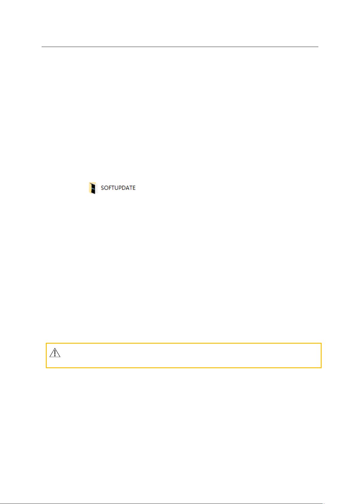
2.Put the folder on the computer (the folder name is SOFTUPDATE, you can't
change the file name, otherwise you can't complete the upgrade). The whole copy is in the root directory
of the U disk (that is, open the U disk directly)
5.2 System software upgrade
After preparing for the work, perform the following software upgrades:
1) Press the power button and the machine starts:
2) The machine will automatically enter the upgrade interface, please wait for the machine
upgrade to complete:
3) Wait a few minutes to upgrade, the screen appears "system update successed, please
restart", you can reboot.
Caution
52
Page 53

Defibrillator Monitor S Series Service Manual
sales personnel to see if the upgrade software meets your
Please check with Comen after-
instrument.
Do not connect the monitor to the patient during the upgrade.
The upgrade process will last for 30 seconds - 2 minutes. Please ensure that there is sufficient
battery power or AC power.
The upgrade of the program can only be operated by professional after-sales personnel.
Do not remove or insert a USB flash drive while the software is being upgraded.
53
Page 54

Defibrillator Monitor S Series Service Manual
Chapter 6 Performance Verification
6.1 NIBP test
6.1.1 NIBP Air leak test
requirements:
Adult non-invasive blood pressure cuff
Suitable catheter
Cylinder
Please follow the steps below to do the performance test:
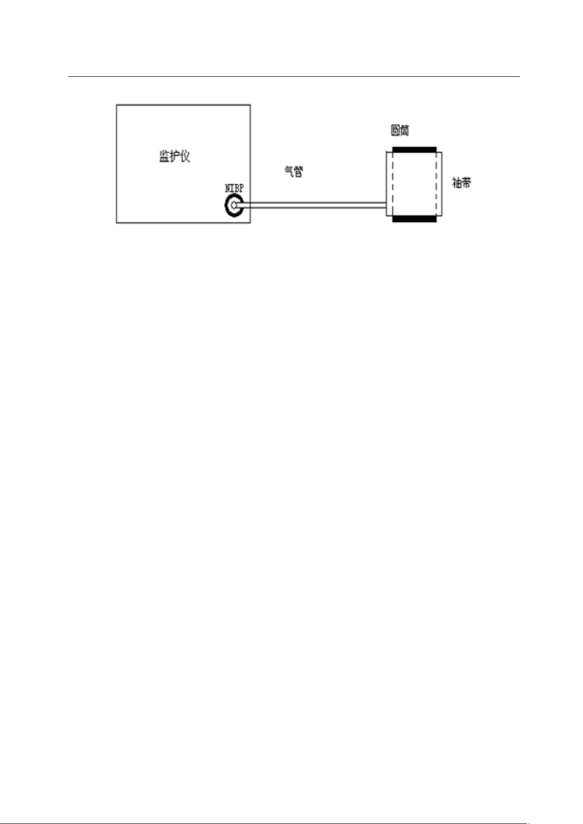
1) Connect the cuff to the NIBP air vent of the monitor.
2) Wrap the cuff around a suitably sized cylinder.
3) Select [NIBP] in the parameter area, and select [Leakage Detection] in the [NIBP
Settings] menu that pops up.
4) At this time, “leakage detection...” will be displayed below the NIBP parameter area
on the screen, and the table system will start to perform air leak detection.
5) The system is automatically inflated to a pressure of 180 mmHg.
6) After about 20 seconds, the system will automatically open the bleed valve to mark
the completion of the leak measurement.
If there is no prompt information in the NIBP parameter area, the table shows that there
is no air leakage. If “Pump leak...” is displayed, there may be a leak in the gas path. At
this point, the operator should check whether the entire connection is loose. After confirming
that the connection is correct, perform another leak detection. If there is still a fault
indication, please contact the manufacturer for repair.
54
Page 55
Defibrillator Monitor S Series Service Manual
6.1.2 NIBP Pressure calibration
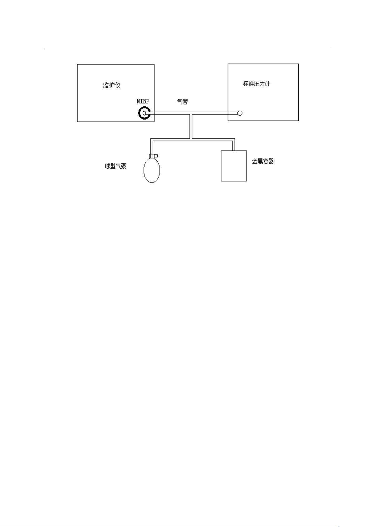
Figure 5
requirements:
T-type interface
suitable trachea
ball type air pump
Metal container: 500 ± 25 ml
Sphygmomanometer (for reference): use a calibrated pressure gauge with an accuracy
greater than 1mmHg
Please follow the steps below to do the performance test:
1. Connect the monitor, pressure gauge, spherical air pump and metal container
(instead of the cuff) as shown in the figure below。
55
Page 56
Defibrillator Monitor S Series Service Manual
Figure 6
2. The pressure gauge reading should be zero before inflation. If it is not zero, open the ball pump valve
so that the entire gas path leads to the atmosphere, and then close the valve after the standard
pressure gauge reads zero.
3. In the [Monitor Maintenance] menu, select [User Maintenance], enter the password and enter the
[User Maintenance] menu, select [NIBP Check], and set the monitor to "Check" mode.。
4. The pressure in the metal container was inflated to 0, 50 and 200 mmHg by a ball type air pump.
The difference between the value of the standard pressure gauge and the pressure indicated by the
monitor should be within 3 mmHg. Otherwise, please contact the Comen service engineer.。
6.2 IBP test
Test requirements:
Invasive blood pressure simulator, IBP accessory.
Please follow the steps below to do the performance test:
1. Connect the invasive pressure simulator and monitor through the accessory, set the
output static pressure of the invasive pressure simulator to 0mmHg (0kPa), change
the current IBP channel pressure name in the monitor to ART and zero, the system
should prompt the school Zero success, and the average pressure value is also shown
as 0 mmHg (0 kPa).
56
Page 57

Defibrillator Monitor S Series Service Manual
2. Set the static pressure value of the artificial pressure simulator to 100mmHg, 200mmHg,
dynamic pressure value 120/80mmHg, the pressure display range of the current channel
should be (0~1mmHg, 98~102mmHg, 196~204mmHg, (118~122) / (79 ~ 81) mmHg).
3. Repeat the above steps for IBP channels 2, 3, and 4.
6.3 ECG test
Test requirements:
ECG lead, heart" simulator.
Please follow the steps below to do the performance test:
Use ECG lead and ECG simulator to connect one by one. After the ECG simulator is powered
on, press the “NSR” button of the ECG simulator to observe the HR value of the simulator
screen and the ECG waveform of the monitor. After stabilization, the HR value of the
instrument screen is ±1% or ±1bmp.
6.4 SpO
test
2
requirements requirements:
SPO2 probe
Please follow the steps below to do a performance test:
1. Connect the SPO2 probe to the monitor. Set the patient type to adult.
2. Test SPO2 on your finger. (assuming you are in good health)
3. Check the volumetric and pulse rate readings to ensure that the SPO2 value is in the
range of 95%-100%.
4. Remove the SPO2 sensor from your finger and the value and waveform gradually become
zero.
57
Page 58

Defibrillator Monitor S Series Service Manual
6.5 TEMP test
requirements requirements:
Constant temperature water bath, standard mercury thermometer with a graduation value of 0.05 °C.
Please follow the steps below to do a performance test:
The standard mercury thermometer with a graduation value of 0.05 ° C and the monitor
body temperature sensor are closely attached together, and the thermostatic water bath
is placed at the same time, and the water temperature of the constant temperature water
bath is adjusted. Compare the measured value of the monitor with the standard thermometer
degree. In order to ensure the reliability of the test, the volume of water is required
to be not less than 2L, the water depth is not less than 10cm, and the water temperature
is uniform after being fully stirred. Using a constant temperature water bath and a
standard thermometer, select the temperature point of 0 ° C, 37 ° C, 50 ° C, the
monitor body temperature probe and thermometer are simultaneously put into the water bath
for testing, the test results should be displayed in the following range: 0 ~ 0.1 ° C,
36.9 ~37.1 ° C, 49.9 ~ 50.1 ° C
58
Page 59

Defibrillator Monitor S Series Service Manual
59
 Loading...