

Page 1
COMELIT RAS SOLUTION MANAGEMENT SOFTWARE
Please read this manual thoroughly before use, and keep it handy for future reference.
Page 2

Table of Contents
Chapter 1 — Introduction ...................................................................................... 1
1.1 Features .................................................................................................................................................................... 1
1.2 System Requirements.............................................................................................................................................. 2
Chapter 2 — Installation ....................................................................................... 3
2.1 Installation ............................................................................................................................................................... 3
2.2 Upgrade .................................................................................................................................................................... 3
Chapter 3 – System Setup ..................................................................................... 4
3.1 System Setup ............................................................................................................................................................ 5
3.2 System Setup – Device/Layout/Sequence .............................................................................................................. 6
3.3 System Setup – Discovery ..................................................................................................................................... 11
3.4 System Setup – Schedule ...................................................................................................................................... 15
3.5 System Setup – Disk .............................................................................................................................................. 17
3.6 System Setup – Layout ......................................................................................................................................... 18
3.7 System Setup – Emap ........................................................................................................................................... 18
3.8 System Setup – Sequence ...................................................................................................................................... 21
Chapter 4 – Event Setup ..................................................................................... 22
4.1 Event Setup – Device ............................................................................................................................................. 22
4.2 Event Setup – System ............................................................................................................................................ 24
4.3 Event Setup – SMTP ............................................................................................................................................. 24
4.4 Event Setup – Relay Out ...................................................................................................................................... 26
Chapter 5 – User Setup ....................................................................................... 27
5.1 User Setup – User .................................................................................................................................................. 27
5.2 User Setup – Authority ......................................................................................................................................... 28
Chapter 6 – Option Setup .................................................................................... 30
6.1 Option Setup – System .......................................................................................................................................... 30
6.2 Option Setup – Video ............................................................................................................................................ 33
Chapter 7 – Main/Sub Menu ............................................................................... 35
7.1 Main Menu ............................................................................................................................................................ 35
7.2 Sub Menu ............................................................................................................................................................... 37
7.3 Tray Menu ............................................................................................................................................................. 38
Chapter 8 - Joystick ............................................................................................. 39
8.1 Joystick Connect / Disconnect ................................................................................................................... 39
8.2 Joystick Functions .......................................................................................................................................... 39
Chapter 9 – Device Tree ...................................................................................... 41
9.1 Device ..................................................................................................................................................................... 41
9.2 Layout .................................................................................................................................................................... 44
9.3 Channel Sequence ................................................................................................................................................. 45
9.4 Layout Sequence ................................................................................................................................................... 45
9.5 Favorite............................................................................................................................................................... 46
II
Page 3

Chapter 10 – Live View ....................................................................................... 48
10.1 Live View.............................................................................................................................................................. 48
10.2 PTZ Control......................................................................................................................................................... 50
10.3 Live Toolbar ......................................................................................................................................................... 52
10.4 Event List ............................................................................................................................................................. 55
Chapter 11 – Local Playback ............................................................................... 57
11.1 Date and Time Search ......................................................................................................................................... 57
11.2 Playback Controls ............................................................................................................................................... 58
11.3 Event Search ........................................................................................................................................................ 62
11.4 Favorite Search (Bookmark) .............................................................................................................................. 64
11.5 Event Report ........................................................................................................................................................ 65
11.6 Local File Playback ............................................................................................................................................. 66
11.7 Playback Toolbar ................................................................................................................................................. 68
Chapter 12 – Device Playback ............................................................................. 70
12.1 Date and Time ..................................................................................................................................................... 70
12.2 Playback Controls ............................................................................................................................................... 70
12.3 Event Search ........................................................................................................................................................ 71
12.4 Text-In Search ..................................................................................................................................................... 71
12.5
Device Playback Toolbar .................................................................................................................... 73
Chapter 13 – Emap View ..................................................................................... 76
13.1 Emap View ........................................................................................................................................................... 76
13.2 Emap Toolbar ...................................................................................................................................................... 77
Chapter 14 – Event View ..................................................................................... 80
14.1 Event View ........................................................................................................................................................... 80
14.2 Event Toolbar ...................................................................................................................................................... 81
14.3 Event List ............................................................................................................................................................. 81
Chapter 15 – Status View .................................................................................... 82
15.1 Status Toolbar ...................................................................................................................................................... 82
15.2 Device Status ........................................................................................................................................................ 83
15.3 System Status ....................................................................................................................................................... 85
15.4 Device System/Event Logs .................................................................................................................................. 86
Chapter 16 – Clip Viewer ..................................................................................... 88
16.1 Export Footage .................................................................................................................................................... 88
16.2 Open Local File ................................................................................................................................................... 89
16.3 Playback Control ................................................................................................................................................. 89
16.4 Event View ........................................................................................................................................................... 89
16.5 Split Mode( ).................................................................................................................................................. 90
16.6 Snapshot ............................................................................................................................................................... 90
16.7 Previous Split Group / Next Split Group .......................................................................................................... 90
APPENDIX A-SPECIFICATION ............................................................................. 91
APPENDIX B-TOOLBARS ..................................................................................... 93
II
Page 4

APPENDIX C-DIRECTORIES ................................................................................ 96
Appendix D-Keys ................................................................................................. 97
Appendix E-Messages and Logs .......................................................................... 98
II
Page 5

List of Figures
FIGURE 1 LOGIN .............................................................................................................................................................. 4
FIGURE 2 ADD/MODIFY/REMOVE COMPUTER ......................................................................................................... 4
FIGURE 3 SYSTEM SETUP MENU ................................................................................................................................. 5
FIGURE 4 SETUP LOGIN ................................................................................................................................................. 5
FIGURE 5 SYSTEM SETUP .............................................................................................................................................. 6
FIGURE 6 ADD DEVICE .................................................................................................................................................. 7
FIGURE 7 ADD LAYOUT................................................................................................................................................. 8
FIGURE 8 LAYOUT .......................................................................................................................................................... 9
FIGURE 9 SEQUENCE .................................................................................................................................................... 10
FIGURE 10 DEVICE SEARCHING ................................................................................................................................ 11
FIGURE 11 SYSTEM SETUP - DISCOVERY ................................................................................................................ 11
FIGURE 12 DEVICE TYPE SEARCH ............................................................................................................................ 12
FIGURE 13 IP FILTERED DEVICE DISCOVERY ........................................................................................................ 13
FIGURE 14 DEVICE MENU ........................................................................................................................................... 13
FIGURE 15 REMOTE SETUP ......................................................................................................................................... 13
FIGURE 16 SYSTEM SETUP - WEEKLY SCHEDULE ................................................................................................ 16
FIGURE 17 SYSTEM SETUP - SPECIAL DAY SCHEDULE ....................................................................................... 17
FIGURE 18 DISK ............................................................................................................................................................. 18
FIGURE 19 EMAP ........................................................................................................................................................... 19
FIGURE 20 USER IMAGE SIZE ..................................................................................................................................... 20
FIGURE 21 EVENT SETUP ............................................................................................................................................ 22
FIGURE 22 EVENT SETUP - DEVICE .......................................................................................................................... 22
FIGURE 23 EVENT SETUP - SYSTEM ......................................................................................................................... 24
FIGURE 24 EVENT SETUP - SMTP ............................................................................................................................... 25
FIGURE 25 EVENT SETUP - RELAY OUT ................................................................................................................... 26
FIGURE 26 USER SETUP ............................................................................................................................................... 27
FIGURE 27 SETUP USER ............................................................................................................................................... 28
FIGURE 28 OPTION SETUP ........................................................................................................................................... 30
FIGURE 29 OPTION SETUP - SYSTEM ........................................................................................................................ 30
FIGURE 30 OPTION SETUP - VIDEO ........................................................................................................................... 33
FIGURE 31 OPTION SETUP - OSD................................................................................................................................ 34
FIGURE 32 MAIN MENU/SUB MENU .......................................................................................................................... 35
FIGURE 33 LOGIN DIALOG - OPTION ........................................................................................................................ 36
FIGURE 34 MAIN MENU ............................................................................................................................................... 36
FIGURE 35 SUB MENU .................................................................................................................................................. 37
FIGURE 36 TRAY MENU ............................................................................................................................................... 38
FIGURE 37 JOYSTICK ..................................................................................................................................................... 39
FIGURE 38 DEVICE TREE ............................................................................................................................................. 41
FIGURE 39 DEVICE MENU ........................................................................................................................................... 42
FIGURE 40 DEVICE PROPERTIES ............................................................................................................................... 43
FIGURE 41 RECORDING PROPERTY .......................................................................................................................... 43
FIGURE 42 NVR DEVICE MENU .................................................................................................................................. 44
FIGURE 43 LAYOUT ITEM ........................................................................................................................................... 44
FIGURE 44 CHANNEL SEQUENCE ITEM ................................................................................................................... 45
FIGURE 45 LAYOUT SEQUENCE ITEM ...................................................................................................................... 45
FIGURE 46 FAVORITE .................................................................................................................................................... 46
FIGURE 47 ADD USER LAYOUT .................................................................................................................................... 46
FIGURE 48 MODIFY USER LAYOUT .............................................................................................................................. 47
FIGURE 49 FAVORITE – DEFAULT SETTING .............................................................................................................. 47
FIGURE 50 MAIN ............................................................................................................................................................ 48
FIGURE 51 SET EVENT CHANNEL ............................................................................................................................. 50
FIGURE 52 PTZ CONTROL PANEL .............................................................................................................................. 50
FIGURE 53 PTZ IN SCREEN .......................................................................................................................................... 51
FIGURE 54 ZOOM CONTROL OF PTZ IN SCREEN ................................................................................................... 51
FIGURE 55 LIVE VIEW TOOLBAR .............................................................................................................................. 52
FIGURE 56 LIVE SCREEN TITLE AND TOOLBAR .................................................................................................... 54
FIGURE 57 EVENT LIST ................................................................................................................................................ 55
FIGURE 58 PLAYBACK VIEW ...................................................................................................................................... 57
FIGURE 59 PLAYBACK CALENDAR CONTROL ....................................................................................................... 58
FIGURE 60 TIME COMBO-BOX ................................................................................................................................... 59
FIGURE 61 REMOTE EXPORT ...................................................................................................................................... 59
II
Page 6

FIGURE 62 INSERT FAVORITE .................................................................................................................................... 60
FIGURE 63 PLAY SPEED CONTROL ........................................................................................................................... 61
FIGURE 64 TIME OVERLAPPED PLAYING ................................................................................................................ 62
FIGURE 65 EVENT SEARCH ......................................................................................................................................... 63
FIGURE 66 FAVORITE SEARCH .................................................................................................................................. 64
FIGURE 67 EVENT REPORT ......................................................................................................................................... 65
FIGURE 68 LOCAL FILE PLAYBACK ......................................................................................................................... 66
FIGURE 69 LOCAL EXPORT ......................................................................................................................................... 67
FIGURE 70 TIME BAR .................................................................................................................................................... 67
FIGURE 71 LOCAL PLAYBACK TOOLBAR ............................................................................................................... 68
FIGURE 72 PLAYBACK VIEW SPLIT CONTROL ...................................................................................................... 68
FIGURE 73 PLAYBACK SCREEN TITLE AND TOOLBAR ....................................................................................... 69
FIGURE 74 DEVICE PLAYBACK ................................................................................................................................. 70
FIGURE 75 TEXT-IN SEARCH ...................................................................................................................................... 71
FIGURE 76 TEXT-IN VIEW ........................................................................................................................................... 72
FIGURE 77 TEXT-IN FILTER ........................................................................................................................................ 73
FIGURE 78 DEVICE PLAYBACK TOOLBAR .............................................................................................................. 73
FIGURE 79 SCREEN TITLE AND TOOLBAR .............................................................................................................. 74
FIGURE 80 EMAP VIEW ................................................................................................................................................ 76
FIGURE 81 EMAP TOOLBAR ........................................................................................................................................ 78
FIGURE 82 EVENT VIEW .............................................................................................................................................. 80
FIGURE 83 STATUS VIEW ............................................................................................................................................ 82
FIGURE 84 STATUS TOOLBAR .................................................................................................................................... 82
FIGURE 85 DEVICE STATUS TABLE .......................................................................................................................... 84
FIGURE 86 SPLIT STATUS ............................................................................................................................................ 84
FIGURE 87 SYSTEM STATUS ....................................................................................................................................... 85
FIGURE 88 SYSTEM LOG FILTER ............................................................................................................................... 85
FIGURE 89 LOG SEARCH RESULT .............................................................................................................................. 86
FIGURE 90 DEVICE SYSTEM/EVENT LOG ................................................................................................................ 87
FIGURE 91 CLIP VIEWER ............................................................................................................................................. 88
FIGURE 92 EXPORT FOOTAGE.................................................................................................................................... 88
FIGURE 93 EVENT VIEW .............................................................................................................................................. 89
II
Page 7

List of Tables
TABLE 1 SYSTEM REQUIREMENTS ............................................................................................................................. 2
TABLE 2 DEVICE TREE BUTTONS ............................................................................................................................. 11
TABLE 3 DISCOVERY LIST ITEM ICON .................................................................................................................... 12
TABLE 4 DISCOVERY TOOLS ..................................................................................................................................... 12
TABLE 5 MAINTENANCE ............................................................................................................................................. 14
TABLE 6 COLOR VS. MEANING IN THE TIME TABLE ........................................................................................... 16
TABLE 7 EMAP CONTROL BUTTONS ........................................................................................................................ 20
TABLE 8 DEVICE EVENT OPERATIONS .................................................................................................................... 23
TABLE 9 LIVE UPDATE CHECK .................................................................................................................................. 32
TABLE 10 DEVICE STATUS ......................................................................................................................................... 42
TABLE 11 SEQUENCE CONTROL TOOLS AND OPERATIONS .............................................................................. 49
TABLE 12 JOYSTICK BUTTONS AND PTZ OPERATIONS ....................................................................................... 52
TABLE 13 VIEW TOOLBAR .......................................................................................................................................... 53
TABLE 14 TOOLBAR POSITION .................................................................................................................................. 53
TABLE 15 CALENDAR CONTROLS ............................................................................................................................ 58
TABLE 16 PLAY CONTROLS ........................................................................................................................................ 61
TABLE 17 TIME JUMP ................................................................................................................................................... 62
TABLE 18 EMAP ZOOM CONTROLS .......................................................................................................................... 78
TABLE 19 EMAP LINK CONTROLS ............................................................................................................................. 78
TABLE 20 STATUS TOOLBAR BUTTONS .................................................................................................................. 82
TABLE 21 DEVICE STATUS TABLE ............................................................................................................................ 83
TABLE 22 DEVICE STATUS TABLE TEXT COLORS ................................................................................................ 83
II
Page 8

Chapter 1 — Introduction
1.1 Features
This is extremely powerful and intelligent surveillance software. This guide explains how to install the
software as well as how to configure and use.
• 7 monitors for live, playback and status
• 4 live monitors as Live1, Live2, Event and Emap
• Up to 64 splits per live monitor displaying
• Up to 16 splits for playback displaying
• Various layout modes
• Channel and layout sequence mode
• Event channel/layout view
• Multi-layered Emap view
• 64 channels recording
• NVR support
• Unlimited recording disk size and configurable multiple disk and device assignment
• Various recording modes (manual, weekly schedule, special day schedule, event and event-relay
recording)
• Various search modes (time lapse, event and favorite searching) and playback controls
• Remote network device configuration
• Easy PTZ (PTZ panel and in-screen PTZ) and alarm controls
• Useful view and toolbars for easy control (Digital zoom, Audio, Freeze, Manual-Recording, Microphone,
Split controls and etc.)
• User and authority management
• Keyword searching
• Automatic device discovery
• Easy check system and device status and logs
• Automatic/manual check updating and live update
• Event notification, searching and reporting
1
Page 9

1.2 System Requirements
The following are the minimum system requirements for this software
Table 1 System Requirements
Microsoft® Windows® XP Professional (32 bit or 64 bit), Windows Vista™
Enterprise/Ultimate (32 bit or 64 bit), Windows 7 Professional/Enterprise
Operating System
/Ultimate (32 bit or 64 bit)
* Windows 7 recommended
CPU
RAM Minimum 1 GB (4 GB or more recommended)
Network Ethernet (1 Gbit recommended)
Graphics Adaptor
Hard Disk Type E-IDE, PATA, SATA (7200 RPM or faster), Network drives
Hard Disk Space
Joysticks USB PC Compatible Joysticks
DirectX
This software runs as a 32 bit service and application with the 64 bit operating systems.
Intel® Core™2 Quad processors or higher (Core™ i7 processor
recommended)
PCI-Express, minimum 1024 x 768, 16 bit colors (256 MB or more isolated
VGA memory, 1920 x 1080, 32 bit colors recommended)
Minimum 1 GB free disk space available for software
Minimum 4 GB free disk space available for each recording disk
DirectX end-user runtimes (June 2010 and later)
http://www.microsoft.com/download/en/details.aspx?id=8109
2
Page 10

Chapter 2 — Installation
2.1 Installation
Before installation, shut down and remove any previous installed versions.
Do not install this on a network drives, otherwise the software MAY not work properly.
Procedure
1. Insert the software CD/DVD; then click the installation link.
Alternatively, if you are installing the file version, run the installation file from the location.
Depending on your security settings, you MAY get one or more security warnings. If that is the case,
click the Run button.
2. When the installation wizard starts, click ‘next’ to continue.
3. Read and accept the EULA (End User License Agreement), then click ‘next’.
4. Select ‘typical installation’ and follow the instructions.
5. Click Finish to complete the installation.
2.2 Upgrade
With the live updating function, the software may be upgraded at your convenience. The old configuration
will be automatically converted to the new format. The previous configuration will be applied to the
updated software.
You don’t need to remove the current version of the software manually. The installation of the new
version will remove the current version automatically.
Do not use the old version of software with the new configuration. The new configuration MAY not work
with the old version of software.
Back up your current configuration
When you install the new version, it will take the configuration from your old version and convert it to the
new format of configuration automatically. However, we recommend that you make regular backups of
your configuration.
Procedure
1. Create a folder to backup the configuration on a network drive or removable media device.
2. Open ‘My Computer’ with the explorer and C:\ProgramData\Comelit RAS Solution\ (case of Windows 7).
3. Copy the files and folders to your backup folder.
3
Page 11
Chapter 3 – System Setup
After installation, access the software by double-clicking the Comelit RAS Solution desktop shortcut.
Alternatively, use Window’s start menu: Start > All Programs > Comelit RAS Solution > Comelit RAS
Solution.
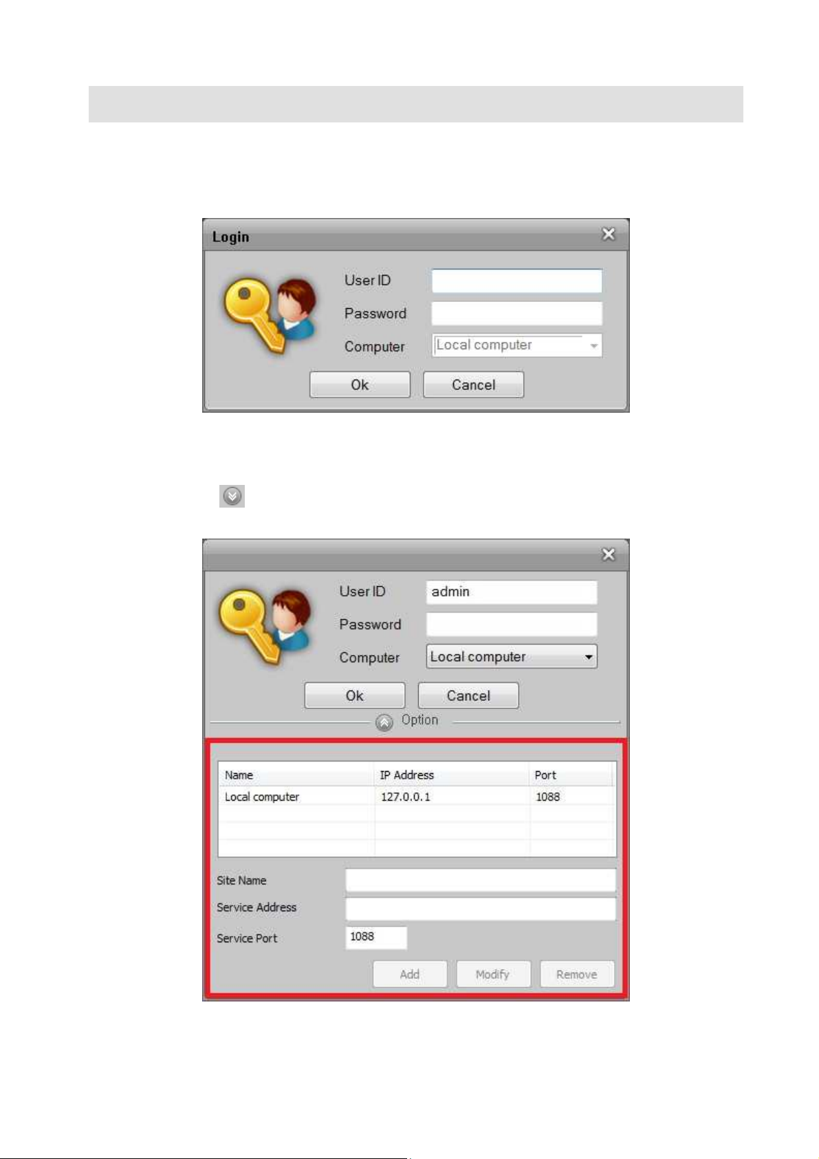
Figure 1 Login
Enter the User ID and Password when prompted by the Login dialog. The default User ID and Password
are “admin” and “admin”. Local computer is the default computer, and user can add/modify/remove
computer by clicking button if needed.
Figure 2 Add/Modify/Remove Computer
4
Page 12
3.1 System Setup
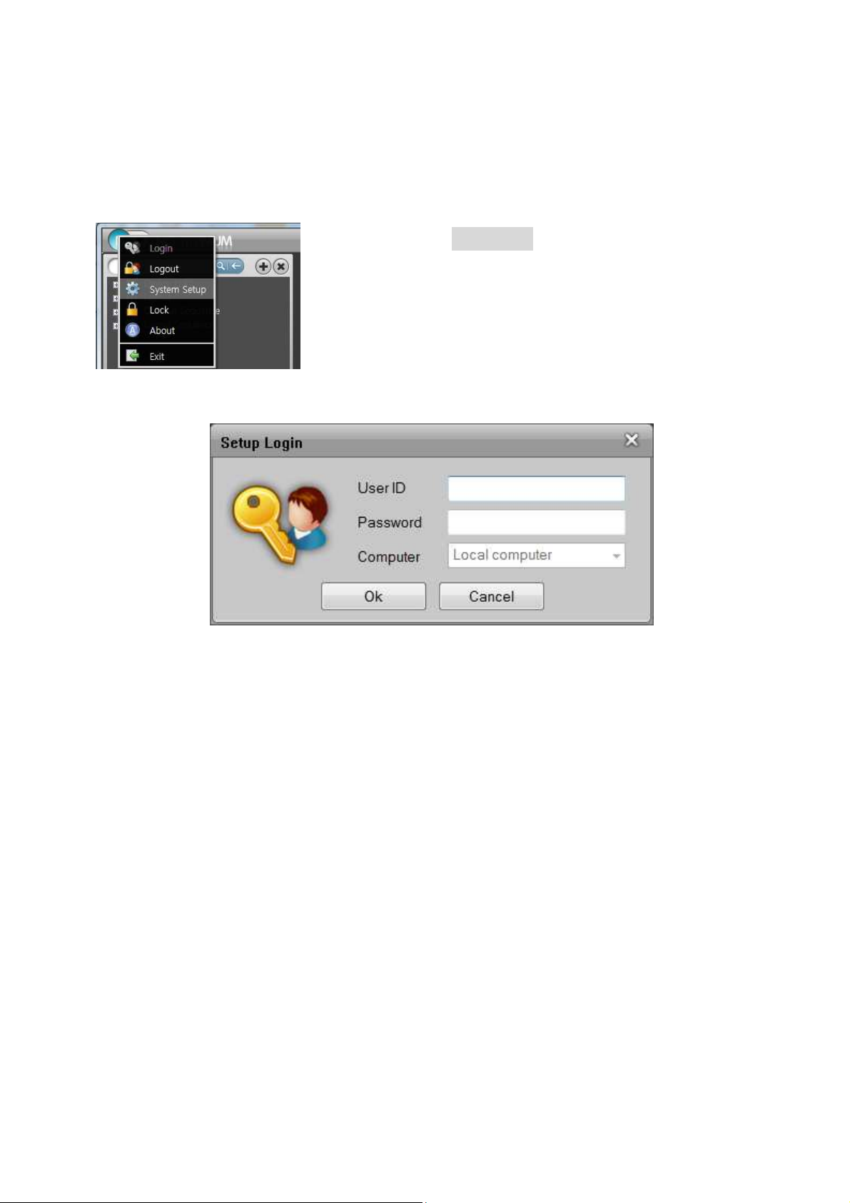
After logging into the software, click the main menu in the title bar and select the System Setup menu.
Figure 3 System Setup Menu
Figure 4 Setup Login
The System Setup requires administrator level authority. Enter the default User ID and Password in the
Setup Login dialog after the first installation.
5
Page 13

Figure 5 System Setup
There are 5 categories: ① main setup menu (SYSTEM, MODULE, EVENT, USER, and OPTION). The ②
device tree is to manage the device group, the device and layout, and the channel and layout sequence.
The ③ configuration property tabs contain menus and configurations for the main setup menu.
3.2 System Setup – Device/Layout/Sequence
The System Setup is to configure devices, layouts, channel and layout sequences and recording
schedule and policy.
The device tree is to manage the device group, device, layout, channel and layout sequence.
3.2.1 Device Group/Device
1) Add device group
① Select the Device root item from the tree.
② Click the right mouse button.
③ Select the Add Group menu from the popup menu.
④ Enter the group name.
2) Rename device group
① Select the device group from the tree to rename it.
② Click the right mouse button.
③ Select the Rename Group menu from the popup menu.
6
Page 14
④ Enter the new group name.
* Press the F2 key to rename the tree item
3) Remove device group
① Select the device group item(s) to remove from the tree.
② Click the right mouse button.
③ Select the Remove Group menu from the popup menu.
④ Confirm removing group from the message.
* When a group is removed, all devices in the group will also be removed. It affects the layout,
channel and layout sequence.
* The recording data will remain even if the device is removed from the configuration.
* Press the Delete key to remove the selected item(s) from the tree.
4) Add devices from the Discovery tab
① Create a group to add a device.
② Select devices (streams) in the Discovery tab and drag into a group to add.
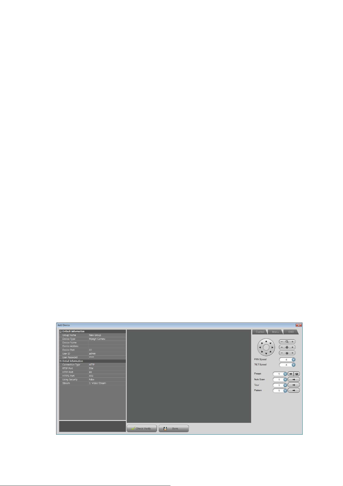
5) Add devices manually
① Create or select a group to add device.
② Click the right mouse button.
③ Select Add Device menu.
④ Edit the device properties (name, address, port, user ID, password and others).
⑤ Click the ‘Check Verify’ button.
⑥ If it connected successfully, click the ‘Save’ button.
Figure 6 Add Device
7
Page 15
3.2.2 Layout
1) Add layout
① Select the Layout root item from the tree.
② Click the right mouse button.
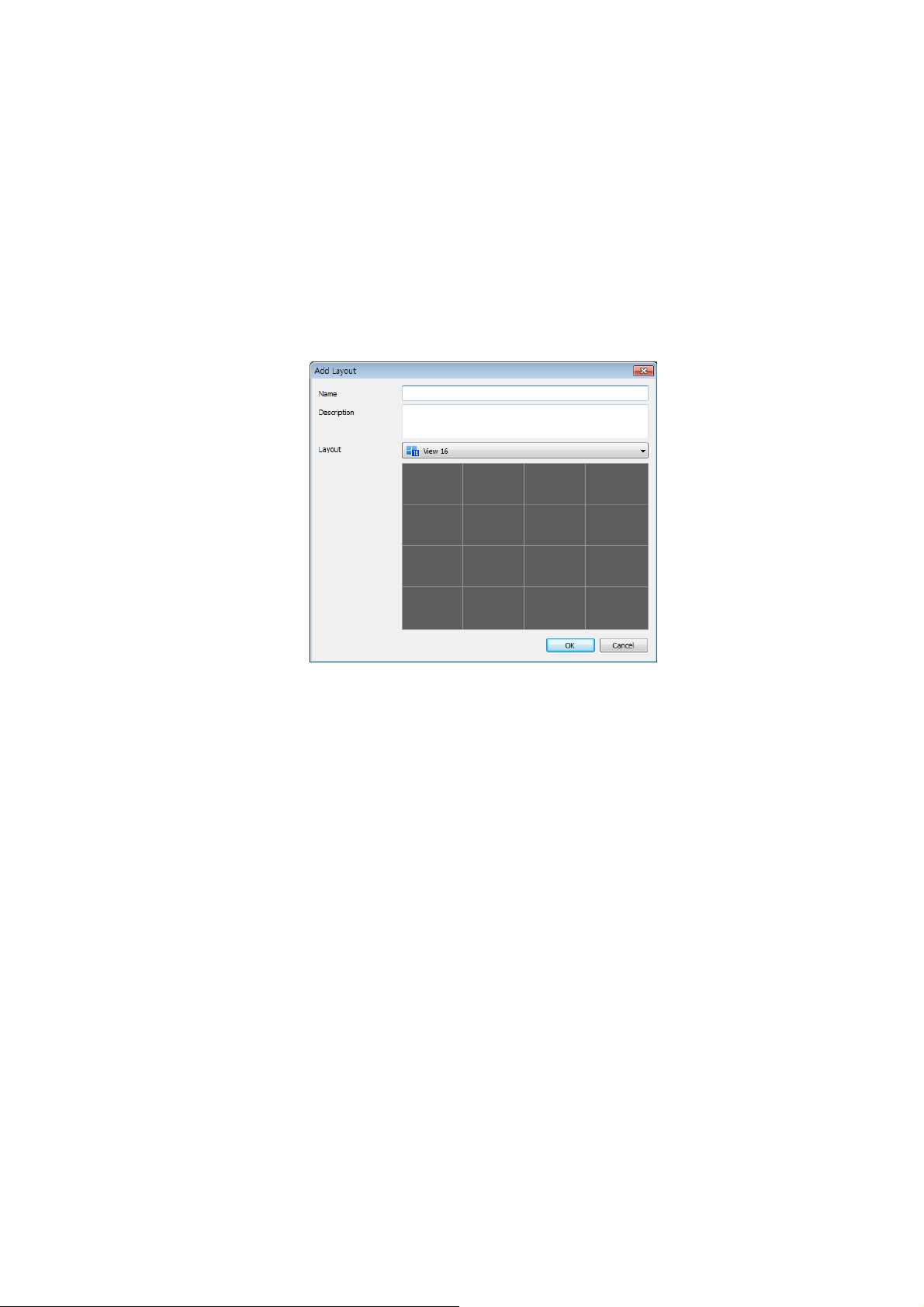
③ Select the Add Layout menu from the popup menu.
④ Enter the layout name and description and select the layout mode in the Add Layout dialog.
Figure 7 Add Layout
2) Rename layout
① Select the layout item to rename from the tree.
② Click the right mouse button.
③ Select the Rename Layout menu from the popup menu.
④ Enter the new layout name.
* Press the F2 key to rename the tree item.
3) Remove layout
① Select the layout item(s) to remove from the tree.
② Click the right mouse button.
③ Select the Remove Layout menu from the popup menu.
④ Confirm removing layout from the message.
* Press the Delete key to remove the tree item(s).
8
Page 16

4) Design layout
① Select the Layout tab and select a layout name in the combo-box.
Figure 8 Layout
② Select a group/(a) device(s) from the tree and drag it into the layout position to set up the device
name.
③ If you want to delete a device from the layout, select the device from the layout and click the right
mouse button.
④ Select the Remove option from the popup menu.
* Press the Delete key to remove the device from the layout in the tree or Layout tab.
3.2.3 Channel/Layout Sequence
1) Add channel/layout sequence
① Select the Channel Sequence / Layout Sequence root item from the tree.
② Click the right mouse button.
③ Select the Add Channel Sequence / Add Layout Sequence menu from the popup menu.
④ Enter the sequence name.
2) Rename channel/layout sequence
① Select the sequence item to rename from the tree.
② Click the right mouse button.
③ Select the Rename Channel Sequence / Rename Layout Sequence menu from the popup menu.
④ Enter the new sequence name.
* Press the F2 key to rename the tree item.
9
Page 17
3) Remove channel/layout sequence
① Select the sequence item(s) to remove from the tree.
② Click the right mouse button.
③ Select the Remove Channel Sequence / Remove Layout Sequence menu from the popup menu.
④ Confirm removing sequence from the message.
* Press the Delete key to remove the tree item(s).
4) Design channel / layout sequence
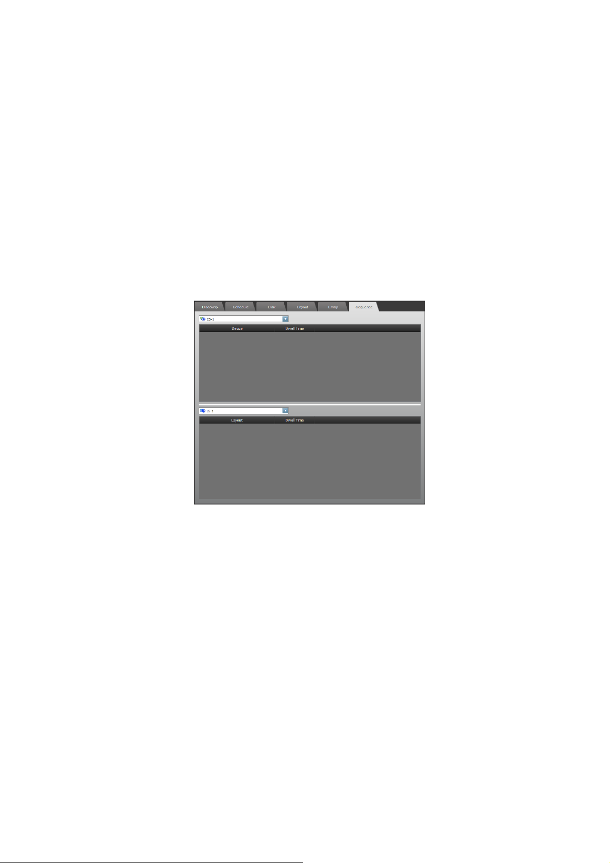
① Select the Sequence tab and select a channel / layout sequence name in the combo-box.
Figure 9 Sequence
② Select a group/(a) device(s)/(a) layout(s) from the tree and drag into the sequence to set up.
③ Set up the dwell time to display device/layout.
④ If you want to delete a device/layout from the sequence, select the device/layout from the
sequence and click the right mouse button.
⑤ Select the Remove menu option from the pop-up menu.
3.2.4 Device searching
There is an edit-box which is for searching device item.
10
Page 18
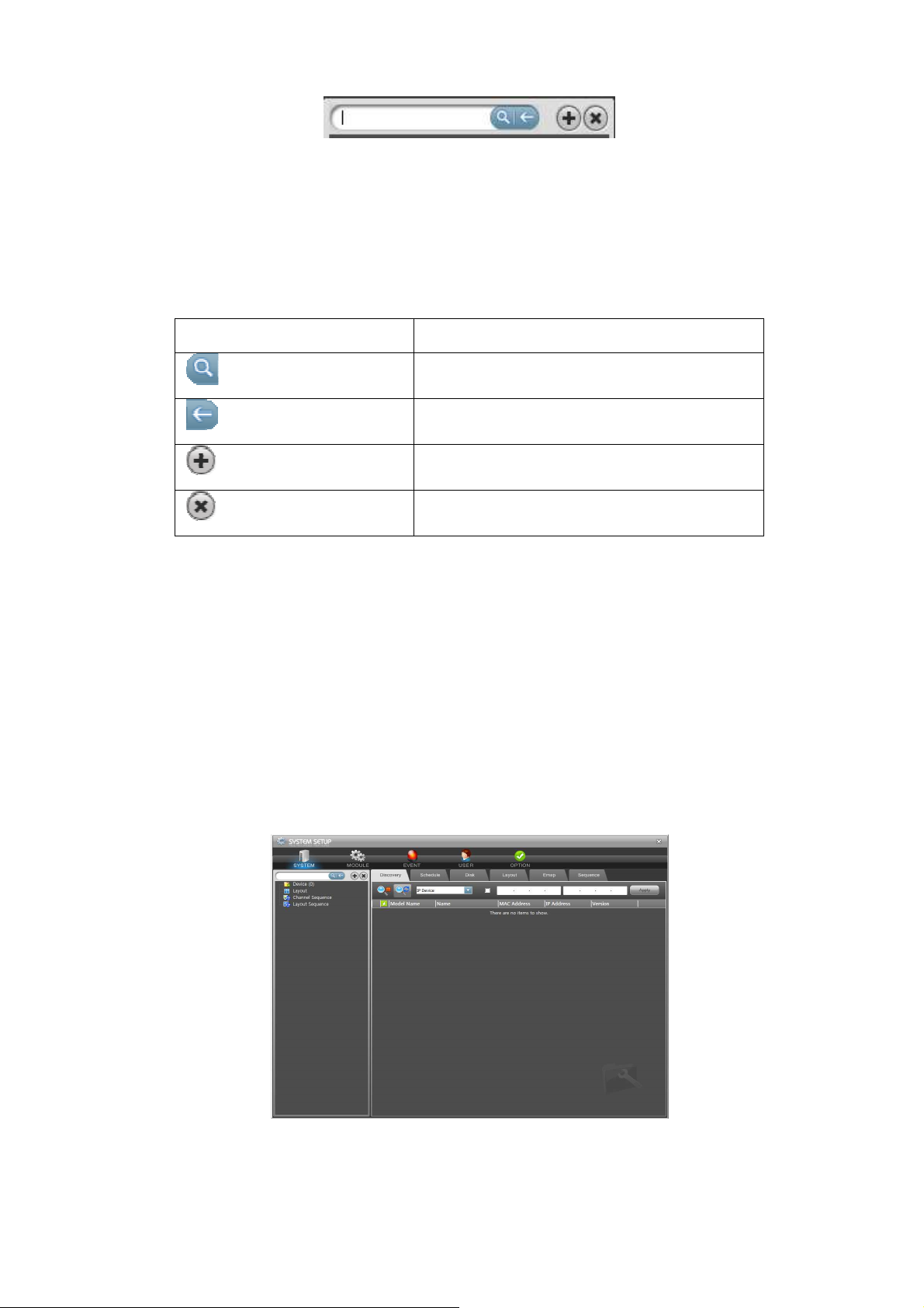
Figure 10 Device Searching
It searches and selects the matching device by item name, IP address, MAC address, firmware version,
URL, model name, profile name. If a layout item has a description or image path that matches with any
searching text, it will automatically be selected.
Table 2 Device Tree Buttons
Device Tree Buttons Operations
Searching device
Clear searching text
Add user dynamic layout
Remove user dynamic layout
3.3 System Setup – Discovery
This option supports automatic device discovery and setup.
3.3.1 Discovery
This feature tries to contact the devices which are attached to the network. It MAY take a few minutes
to complete.
Figure 11 System Setup - Discovery
11
Page 19
1) Connection status
The Discovery tab shows the devices which are connected to the network by model name, device name,
MAC address, IP address and firmware version. Each icon on the item list displays the results of its
connection test.
Table 3 Discovery List Item Icon
Connection Test Results Results Key
2) Discovery tools
The device discovering process is able to be controlled by the below buttons.
Buttons Operations
It’s not available to connect
It’s connected
It’s locked and needs ID and password
Table 4 Discovery Tools
Begin device discovery
Halt device discovery
Refresh list and restart device discovery
3) Device Type Search
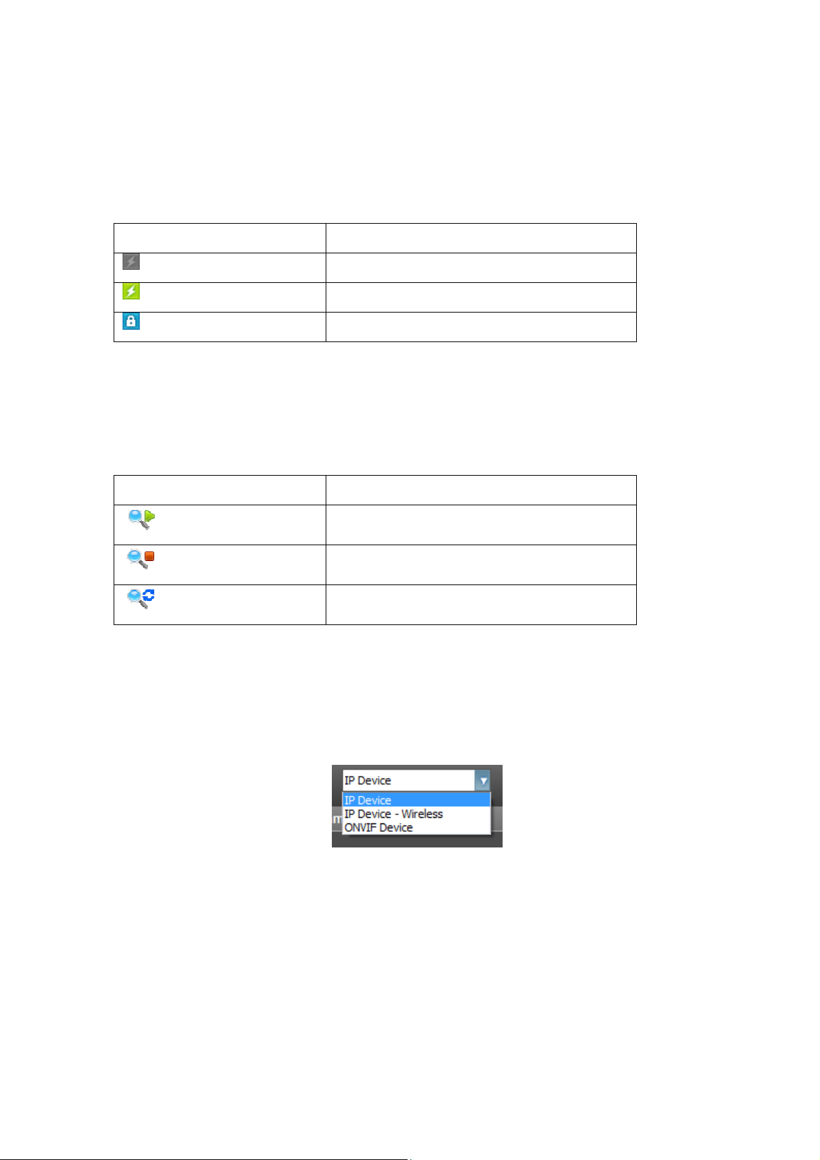
① Select device type for search in combo-box.
② When the device type is selected, corresponding devices in the network are searched and a list of
devices are shown below.
Figure 12 Device Type Search
4) IP filtered device discovery
① Check the IP filter enable button.
② Enter the specific IP address ranges to discover the devices in the network.
③ Click the Apply button. Then the devices are discovered in the specified network address ranges
.
12
Page 20
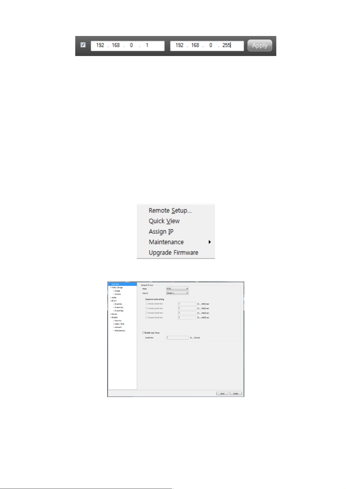
Figure 13 IP Filtered Device Discovery
3.3.2 Device setup
There are some useful tools to setup the devices.
① Select the device item(s) from the list.
② Click the right mouse button.
③ Select the Remote Setup menu.
④ Setup the device configurations. The remote setup dialogs are different depending on the device
model.
* Please refer to the device manual in the setup menu.
* If the Quick View feature is enabled (located in the configuration menu) for the device, you MAY be able
to see the image simultaneously while the configuration is being applied.
Figure 14 Device Menu
Figure 15 Remote Setup
13
Page 21

3.3.3 Quick view
This is to see the video/image stream from the device instantly.
① Select the device item(s) from the list.
② Click the right mouse button.
③ Select the Quick View menu.
④ Select the video/image stream profile and connection type from the combo-boxes.
⑤ The Stop/Play button is to stop and resume the video/image stream.
3.3.4 Assign IP
This is to assign the IP address for the selected device.
① Select the device item(s) from the list.
② Click the right mouse button.
③ Select the Assign IP menu and click the Ok button.
④ The result will automatically assign the selected device with a new IP address.
* After changing the IP address, click the Refresh button. Otherwise, visually, the IP address won’t reflect
the changes.
3.3.5 Maintenance
There are 3 maintenance functions, Restart, Reset and Factory Default. The Reset function MAY be
operated differently depending on the device model.
Table 5 Maintenance
Restart Restarts the device without any changes
Resets the configuration except some specific values (ex. network)
Reset
The client may need to be restarted for the changes to take place.
Resets all configurations to the default factory settings.
Factory Default
The client may need to be restarted for the changes to take place.
* After the Factory Default, the device MAY need some time to recalibrate and connect.
3.3.6 Upgrade firmware
① Select the device item(s) from the list to upgrade.
② Click the right mouse button.
③ Select the Upgrade Firmware menu.
14
Page 22

④ Select the firmware file from the file open dialog.
⑤ The upgrading progress will be shown and it MAY take time to be updated and restarting the system.
* Please check the image file for the device before upgrading. Upgrading the wrong image file MAY cause
the device to malfunction.
3.3.7 Login
This is to set the device login ID and password.
① Select the device item(s) from the list.
② Click the right mouse button.
③ Select the Login menu.
④ Enter the login ID and password.
* The default login ID and password are “admin” and “admin”.
* If the icon of the device shows this symbol , it represents that the login ID and password are not
matched with the device settings.
3.3.8 Emergency Firmware Upgrade
In the case of specific failures, for example halting while upgrading firmware or upgrading wrong image
file, the device MAY be halted. If the network function of the device works properly, it MAY be updated
this way.
① Select the device item(s) from the list.
② Click the right mouse button.
③ Select the Emergency Firmware Upgrade menu.
④ Click the OPEN button and select the correct image file for the device.
⑤ Click the UPDATE button and check the STATUS.
* In the case of specific network device failure, the device MAY not be discovered this way. The
Emergency Firmware Upgrade is only useful when the network function of the device works properly.
3.3.9 Check device
This is to check connection status the selected device.
3.4 System Setup – Schedule
The Schedule tab is to configure weekly/specific event based items.
15
Page 23
3.4.1 Weekly recording schedule
This is to set up weekly-hour based recording schedule.
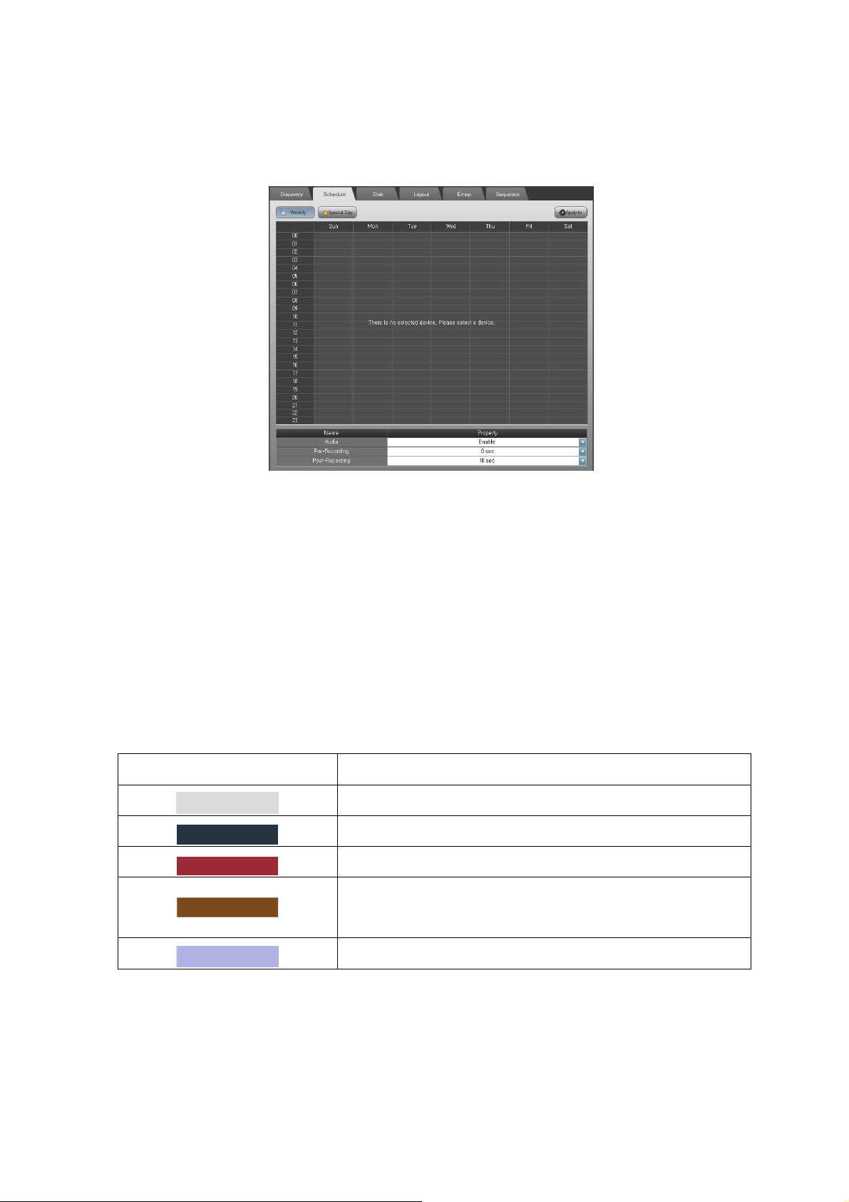
Figure 16 System Setup - Weekly Schedule
① Select the Schedule tab.
② Select a device to set up recording schedule.
③ Click the Weekly button.
④ Select the time table by dragging.
⑤ Click the right mouse button.
⑥ Select the New Time Schedule or New Event Schedule menu.
⑦ If you want to clear the schedule then select the Clear menu
Table 6 Color vs. Meaning in the Time Table
Color of the table Meaning
No schedule
Event recording schedule
Time recording schedule
Adaptive Time/Event schedule
(Normal : key frame only, Event : full-frame recording)
Selected time cell
⑧ Set up the recording properties (Audio, Pre/Post-Recording).
⑨ If you want to apply the same schedule to the other devices, click the ‘Apply to’ button and
select the device(s)/group(s).
* The Pre/Post-Recording values are only for the event recording schedule.
16
Page 24
* If the streams are from the same device then the recording properties are applied to all streams.
* If the Audio is enabled, the audio stream from the device will be recorded with video
3.4.2 Special day recording schedule
This is to set up special day hour based recording schedule.
.
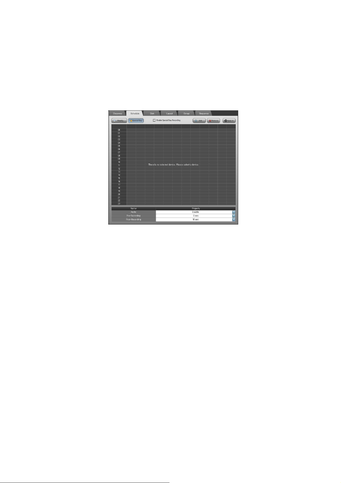
Figure 17 System Setup - Special Day Schedule
① Click the Special Day button.
② Click the Add button to add the special day recording schedule.
③ Double-click the date from the calendar.
④ Set the recording schedule to the desired period.
⑤ If you want to remove the special day schedule, click the Remove button.
⑥ Check the Enable Special Day Recording box to enable it.
⑦ If you want to apply the same schedule to other devices, click the ‘Apply to’ button and select the
device(s)/group(s).
⑧ Set up the recording properties (Audio, Pre/Post-Recording)
⑨ If you want to apply the same special day recording schedule to the others, click ‘Apply to’ button and
select the device(s)/group(s).
* The special day recording priority is higher than the weekly schedule.
3.5 System Setup – Disk
3.5.1 Disk
The Disk tab is to configure the recording hard disk drives and recording policy.
17
Page 25
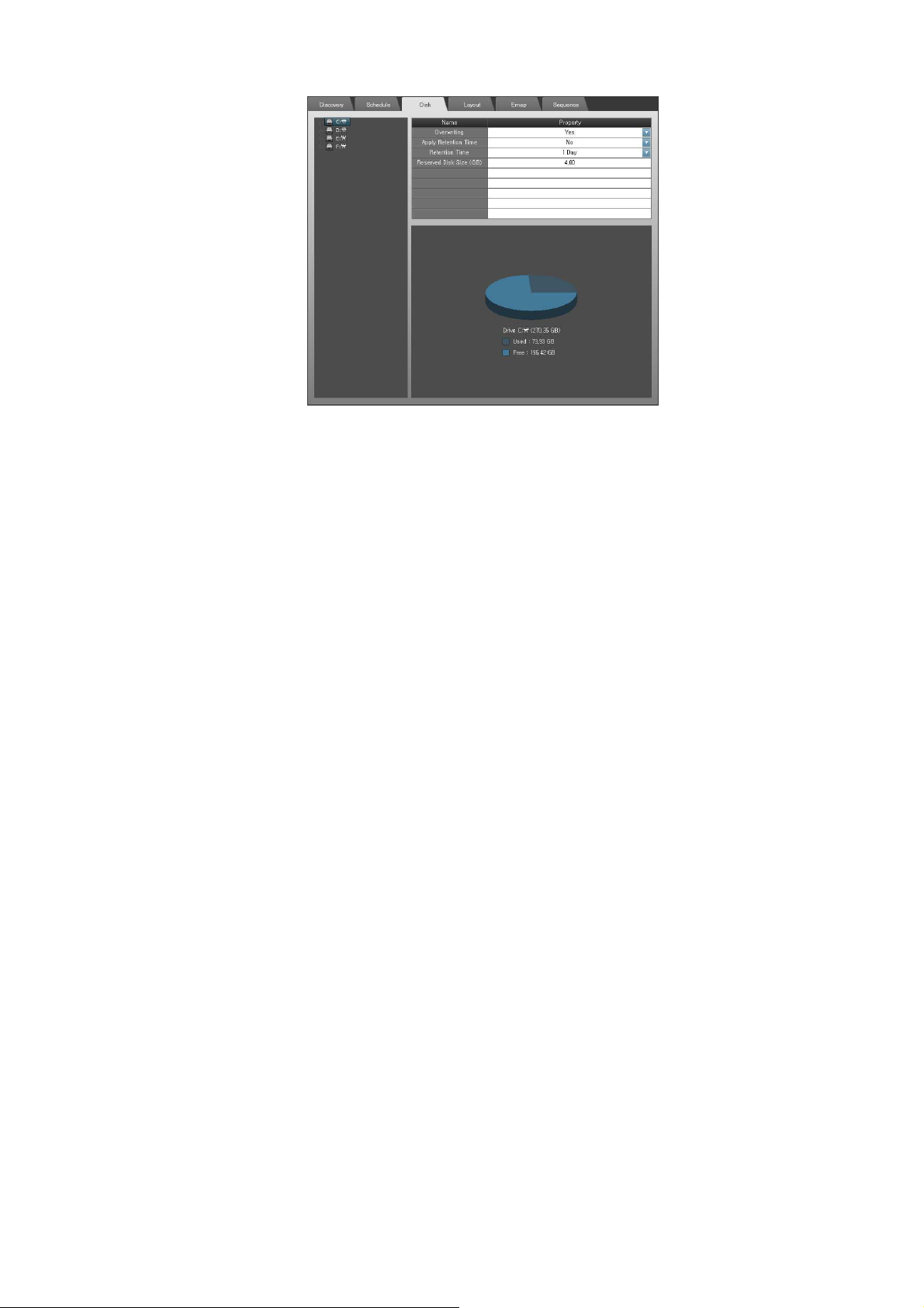
Figure 18 Disk
1) Disk assignment
① Select the Disk tab.
② Select the device(s) from the tree and drag into the disk tree to assign recordings.
③ Set up the recording disk properties.
* The streams which are from the same devices will be assigned automatically to the same disk drives.
* To utilize the disk performance, the streams are assigned to the separate disk drives.
* The Retention Time is to preserve the time of the recording data if the disks are available.
* The Reserved Disk Size is the recording disk size for the selected disk drive.
3.6 System Setup – Layout
This is to design the Layout. The Layout is used to view the layout as well as the Emap. Please refer the
‘3.2.2 Layout for adding, renaming and removing layout’.
3.7 System Setup – Emap
This is to design Emap using the layout.
18
Page 26

Figure 19 Emap
3.7.1 Load background image
① Click the Emap tab.
② Select the Layout item from the combo-box to design Emap.
③ Click the Load Emap Background Image button ( ) and select the image. Available image formats
are JPG, PNG and BMP.
* The recommended Emap background image size is 800 x 600. If the image size is too big, it MAY take a
little time to operate with it. If the image size is too small, E-map design and operation MAY not run
optimally.
* The loaded images (background image, user device, user sensor and user link images) are copied to the
specific directory automatically. If you remove the background images manually from that directory, it
MAY lead to problems in operating Emap functions.
3.7.2 Device design
① Select the device(s) and drag it (them) to your target location.
② Select a device and click the right mouse button.
③ The Rename is to set a specific name only for Emap.
④ The Open Live View option serves to open a popup window displaying the live stream.
⑤ The Change Image option serves to change the device icon.
⑥ If you want to use your own device image, click the Load Emap User Device Image button ( ) and
select the image file. Available image formats are JPG, PNG and BMP. And the height of image MUST be
84 pixels and the width MUST be multiple of 28 pixels.
The top image represents normal, middle does selected, and the bottom is for event notification.
* Please refer the sample images which are installed.
C:\ProgramData\Comelit RAS Solution\MonitoringService\Emap\ (case of Windows 7)
19
Page 27
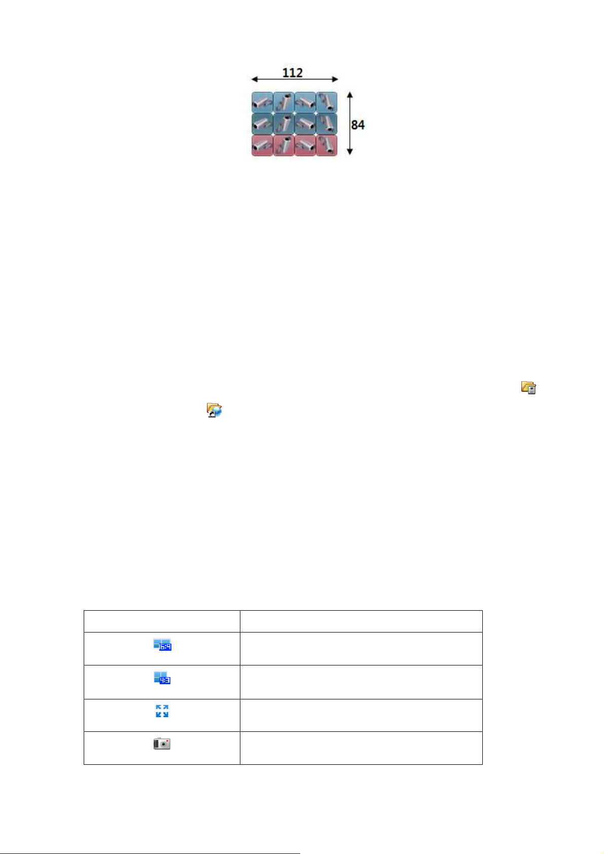
Figure 20 User Image Size
⑦ Select user device image from the Change User Image menu.
3.7.3 Sensor/Link design
① Click right mouse button on the back ground image.
② Select the Insert Sensor/Insert Link menu.
③ Select the device group > device > sensor or manual trigger item.
④ If you want to rename it, click right mouse button and select Rename.
⑤ If you want to the change image, click right mouse button and select Change Image.
⑥ If you want to use your own sensor/link image, click the Load Emap User Sensor Image button ( )/
Load Emap User Link Image ( ). And click right mouse button and select the Change User Image. The
user sensor and link images MUST be the same condition of width and height as above.
* Double-click the link, then the Emap changes to the selected link. You can make a layered Emap with
the link.
* The Manual Trigger is only available if the device supports it. Before designing the manual trigger,
please check the device specification and setup for that operation.
3.7.4 Emap controls
There are some Emap control buttons.
Table 7 Emap Control Buttons
Emap Control Buttons Operations
Wide 16:9 Split Mode (5,7,12,14,20,24,30)
Standard 4:3 Split Mode
(1,4,6,8,9,10,13,16,17,21,25,28,33,34,36,40,49,64)
Full Screen
Snapshot
20
Page 28
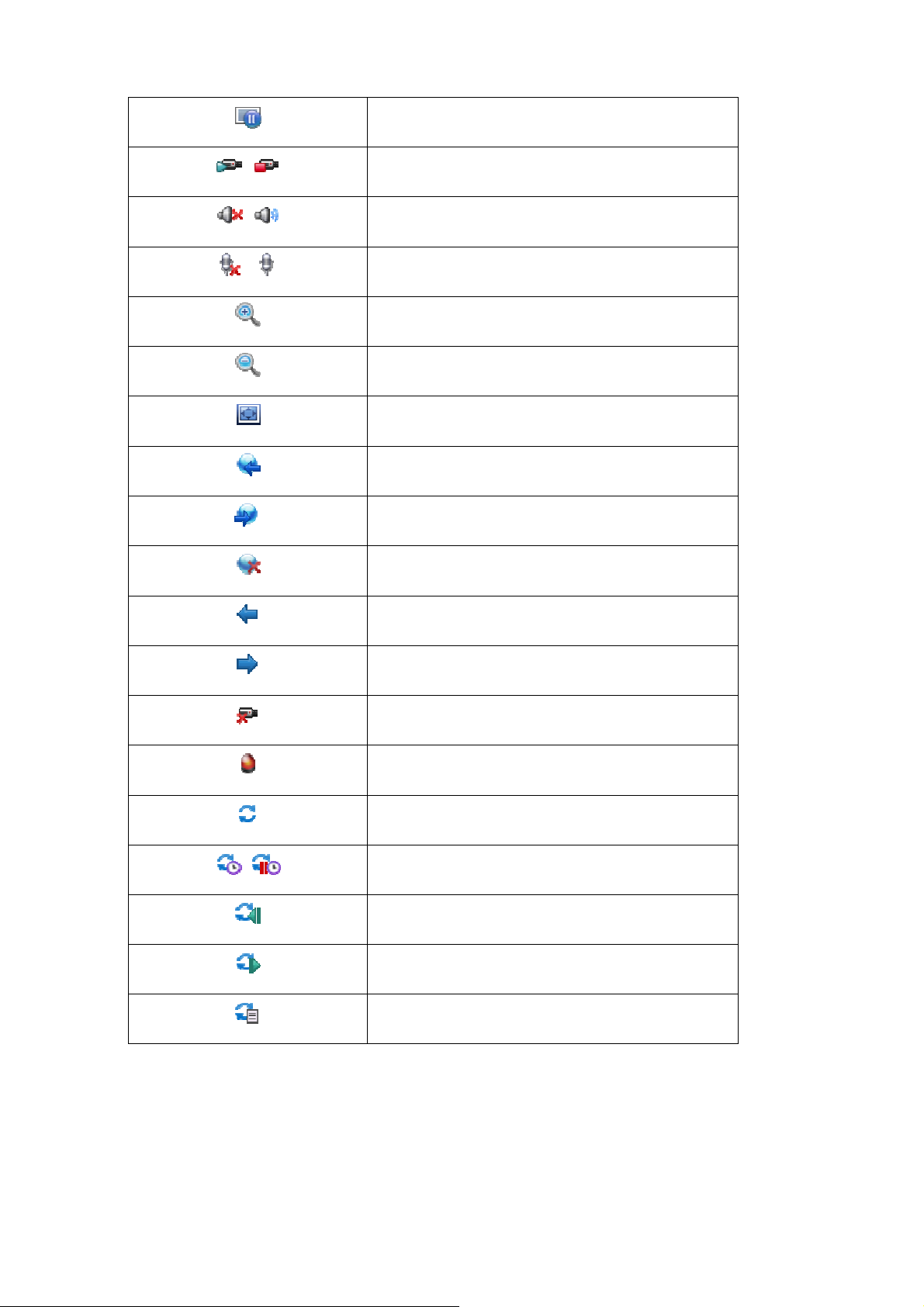
Freeze
Manual Record Off/On
Speaker Mute On/Off
Microphone Mute On/Off
Emap Scale Up
Emap Scale Dawn
Emap Set picture
Previous Emap
next Emap
Emap Close
Previous Split Group
Next Split Group
Disconnect All Devices
Set/Reset Event Channel
Sequence Mode Status/Off
Sequence Timer On/Off
Previous Sequence View Point
Next Sequence View Point
Sequence View Point List
3.8 System Setup – Sequence
This is to set up the channel/layout sequence. Please refer the ‘3.2.3 sequence for adding, renaming and
removing sequence’.
21
Page 29
Chapter 4 – Event Setup
This is to set up event operations. The device events are dependant on the device model. For example,
some devices MAY support only motion and alarm event. And others MAY support manual trigger, on boot,
video loss, network loss as well as motion and alarm. Please check the device model and setup before
configuring this.
Select the EVENT menu.
Figure 21 Event Setup
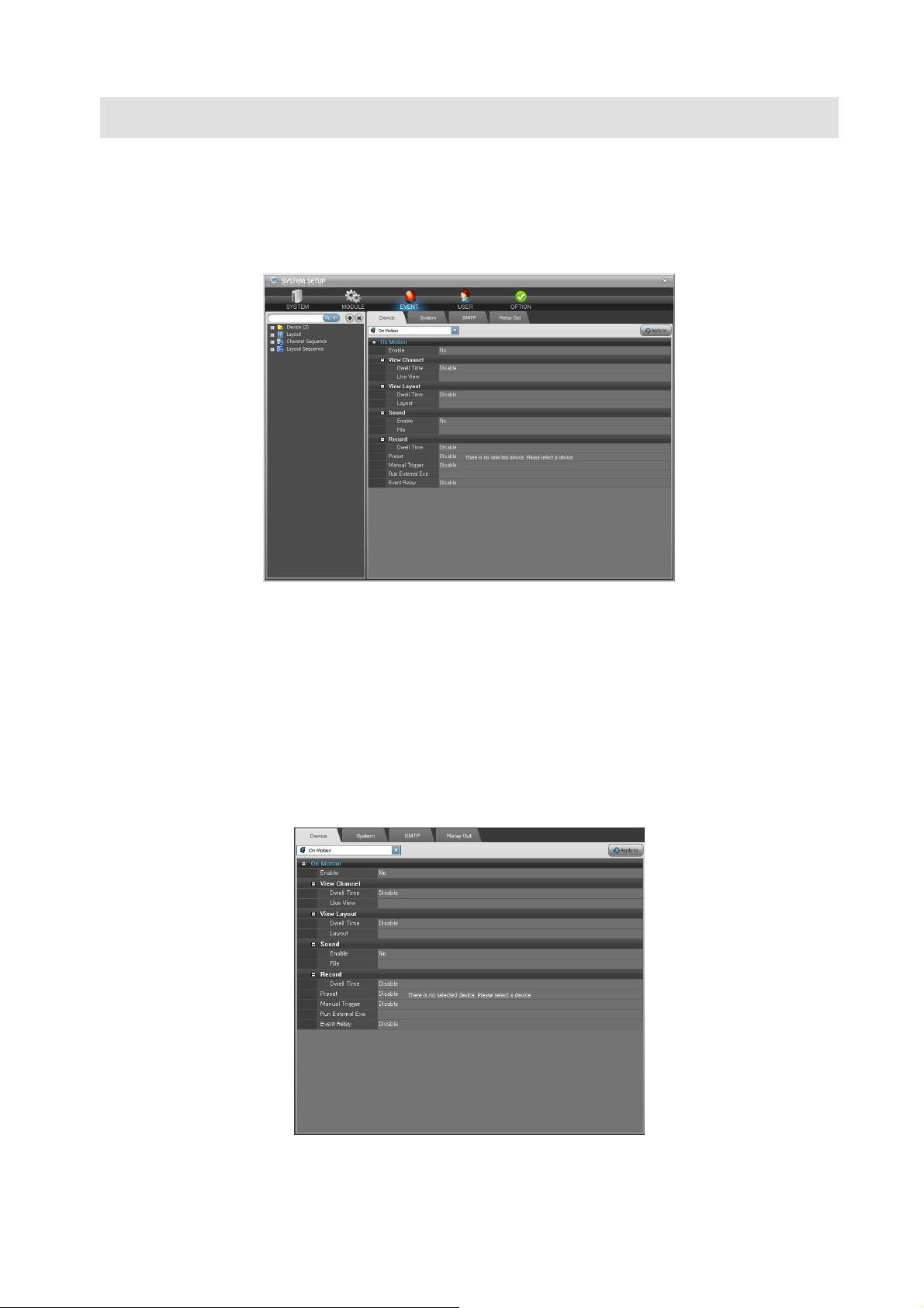
4.1 Event Setup – Device
This is to set up the event operation. When an event happens on the device, the configured operations
(view channel/layout, sound, execute external application, and recording, etc.,) would be worked. And the
Event Relay is to relay event to other devices.
Figure 22 Event Setup - Device
22
Page 30

4.1.1 Event operations
① Select the Device tab.
② Select a device from the device tree.
③ Select an event type to set up from the combo-box.
④ Enable/Disable the selected event operation from the list.
⑤ Set up the event operations.
⑥ If you want to apply the same operations to other devices, select the Apply to button and select
device(s)/group(s).
Table 8 Device Event Operations
Event Operations Options Settings
Enable Yes/No Enable/Disable the event operations
View Channel Dwell Time Amount of time to display the event channel
Live View What view to show the event channel on Live1,
Live2, Emap and All.
View Layout Dwell Time Amount of time to show the layout
Layout What layout to show in the Event view
Sound Enable Enable/Disable the sound
File Select the sound file, otherwise the default sounds
will be automatically be initiated
Record Dwell Time Event Recording independent on schedule
Preset Preset ID In the case of PTZ, move the preset
Manual Trigger Trigger ID If it supports manual trigger, it will trigger
Run External Exe File Execute an external application
Event Relay Relay Out List Select the Relay Out
* The Record operation in the device event list only affects the recording schedule. For example, if there
is a device which is configured that there is no recording (time/event) schedule from 9:00 AM to 10:00 AM.
If an event which operation is recording, is happened during that time, it would be recorded as configured
with above setting value.
* The Relay Out has the similar configurations of the device event. Please do not configure relay chains.
(For example, a manual trigger of device A relays a manual trigger of device B. And manual trigger of
device B relays manual trigger of device A. It makes relay chain continuously. It MAY cause endless event
operations)
* The View Channel option needs event channel setting on the Live1, Live2 and Emap. If there is no event
channel setting on them, it will not work.
* The Dwell Time values of the View Channel and View Layout have a minimum time out of 5 sec. If
another event occurs, the view channel and layout MAY be preemptive even though the value is over 5
seconds.
23
Page 31

4.2 Event Setup – System
This is to set up the system event operations as like Disk Fault, Disk Full and System Update events.
Figure 23 Event Setup - System
4.2.1 System event operations
① Select the System tab.
② Select a system event type to setup from the combo-box.
③ Enable/Disable the selected event operation from the list.
④ Check the SMTP receiver to send the event information mail.
⑤ Enable/Disable the Sound.
⑥ Select the sound file.
* The mail receivers are able to be configured in the SMTP tab. Please refer the ‘4.3 Event Setup – SMTP’.
4.3 Event Setup – SMTP
This is to set up the SMTP settings. When an event is occurs in the system, this will send emails to the
configured instructions.
24
Page 32

Figure 24 Event Setup - SMTP
4.3.1 SMTP setting
① Select the SMTP tab.
② Check/Uncheck the Enable SMTP.
③ The Sender is the email address of the system administrator.
④ The Interval is the mailing interval. The range is from 1 min to 24 hours.
⑤ The Aggregate Events is the count of the events to send.
* If the Interval is 1 minute, this would check event to send every minute. If the Interval is 24 hours, this
would check event to send in a day and send it.
* If the Aggregate Events value is 50, this would not send email until 50 events happened.
* If the Interval is 1 hour and the Aggregate Events value is 50, this would check and send email in every
hour. And if the number of events is over 50, this would send an email every hour.
4.3.2 SMTP server information
① Check/Uncheck the Use Mail Server.
② Fill the mail server address and port to the list.
③ Fill the Login Name and Password of the mail server address.
④ Select the Login Method.
* Without SMTP server information, there MAY be a failure in the email transmission.
4.3.3 Receiver and SMTP Test
The maximum mailing list is 10. If you want to test mailing, enter the receiver address and click the Test
button.
25
Page 33

4.4 Event Setup – Relay Out
This is to set up event relay out. After setting this, each relay out item is selectable in the Device tab.
Please refer the ‘4.1 Event Setup – Device’ to assign the event relay out to the device event.
Figure 25 Event Setup - Relay Out
4.4.1 Event relay out
① Select the Relay Out tab.
② Click the Add button and enter the relay out name.
③ Select the device from the device tree and drag it into the below of the list.
④ Set up the Record, Manual Trigger and Preset.
* The Record is the recording dwell time.
* The Manual Trigger is dependant on the device model.
* The Preset is only available for the PTZ device.
* Before setting up the Manual Trigger and Preset, please check the device model and settings.
* If an event is assigned with relay out, the event will occur as it is configured with Manual Triggering and
PTZ preset movement.
* Do not create a chained relay out, for instance an event from device A triggers the device B and the
event which was triggered by B triggers the device A again and again.
4.4.2 Remove relay out
Select the relay out item from the list. Click the Remove button.
4.4.3 Rename relay out
Double-click the relay out item from the list and enter new name of it.
26
Page 34

Chapter 5 – User Setup
This supports multi-users. Each user is able to be assigned the device, layout and sequences. This
describes how to configure users and authorities. The default administrator user ID is “admin” and the
password is “admin”. After installation, please change the password of the “admin” for safety. The
“admin” is not able to be removed.
Figure 26 User Setup
Save the configuration otherwise the changes will not be applied. The old configuration would be saved in
the specific directory. The old configurations MAY be useful to get technical support. The old configuration
saving directory is C:\Program Data\Comelit RAS Solution\MonitoringService\Logs, case of Windows 7.
This keeps maximum 20 old configurations.
5.1 User Setup – User
Select the User menu.
5.1.1 Add user
① Select the User tab.
② Click the Add button.
27
Page 35

Figure 27 Setup User
③ Select the Group. A member of the Administrator group is capable to setup the system and access all
devices, layouts and sequences. A member of the User group is not able to enter the system setup.
④ If you want to add one user, check/uncheck the Assign All Devices, Layouts, Sequences. If it is not
checked, an administrator SHOULD reassign devices, layouts and sequences.
⑤ Enter the Password and Confirm password fields. And Click the Ok button.
5.1.2 Modify user
① Select a user to modify from the list.
② Double-click it or click the Modify button.
③ Modify the user information and click OK to save.
5.1.3 Remove user
Select a user(s) to remove from the list and click the Remove button.
5.2 User Setup – Authority
This is to assign the devices, layouts and sequences to users.
28
Page 36

5.2.1 Set up authorities
① Select a user from the combo-box.
② Select a device(s) from the device tree and drag it (them) into the Device list.
③ Select a layout(s) from the device tree and drag it (them) into the Layout list.
④ Select a sequence(s) from the device tree and drag it (them) into the Sequence lists.
* If a layout is assigned to a user, all devices which belong to that layout are assigned automatically.
* If a sequence is assigned to a user, all devices which belong to that sequence are assigned
automatically.
⑤ If you want to remove a device(s), layout(s) or sequence(s), select and click right mouse button.
⑥ Select the Remove menu.
* If a user is a member of the Administrator group or is already assigned to all devices, layouts and
sequences, then the user is not listed in the combo-box.
29
Page 37

Chapter 6 – Option Setup
This is to set up various options of system, video and OSD (On Screen Display).
Select the OPTION menu.
Figure 28 Option Setup
6.1 Option Setup – System
This is to configure language, automatic login/logout mode and system live update checking and logs.
Select the System tab.
Figure 29 Option Setup - System
6.1.1 Language
This software supports multi-language functions and the language preference is user-configurable.
30
Page 38

1) User configurable language
You can export the language items from the software in run-time. After editing the exported language file
and place it under the specific directory. Then the language is ready to be used. The procedures are
below.
① Select the System tab.
② Click the Export button in the Language.
③ Select the file to export.
④ Open the exported file (.ini) with text editor. (ex, Notepad)
⑤ Edit the right side strings of the equal mark.
* Do not change the number.
[StringTable]
100=OLE initialization failed. Make sure that the OLE libraries are the correct version.
101=Login
102=Logout
[number]=[string]
* If the system updated, the language file MAY not be compatible with the updated version.
⑥ Place the user language file in the Languages directory under the system using.
(C:\Program Data\Comelit RAS Solution\MonitroingService\Languages\ - case of Windows 7)
⑦ Click the Reload button.
⑧ Select the language file name from the Language combo-box.
⑨ Click the Apply button. The selected language will be applied.
* Some strings MAY not be matched with the window dialog. In that case, please re-define the strings.
* Some of strings would be applied after restarting the software.
2) Multi-languages
The software MAY include some languages. You can select the language from the combo-box and Click
the Apply button. The selected language would be applied.
6.1.2 Authority
This is to set up the automatic login and logout.
1) Automatic login
To login automatically with the specific user, check the Enable automatic login check-box and select the
user to be applied. Otherwise, uncheck it.
31
Page 39

2) Automatic logout
To logout automatically without asking for user confirmation, check the Enable automatic logout without
checking user information. Otherwise, uncheck it.
6.1.3 Abnormal termination
There is a possibility that if the software client is terminated without the correct procedure, the next time
you start the client, you MAY receive a message of abnormal termination. If this is checked, even though
there is any abnormal termination, the last user who logged in will remain logged in and the last Live1,
Live2 views will be restored automatically (without message checking).
6.1.4 System Update
This is an automatic check for software updates. Checking will be done automatically, but updating
software needs user confirmation. This is to configure updating server and method.
① Check the Automatic Check and select the time.
② Enter the update server URL (for example, http://192.168.0.1/liveupdate/Comelit RAS Solution)
③ If the update server requires a user ID and password for accessing, check the user ID/password to
login the update server.
④ Click the Check button to access the server.
Table 9 Live Update Check
After Starting Up Whenever any administrator level user logs in
Before Closing
All
* Please consult the updating server with the network administrator or software installer.
Before the software closing
After Starting Up and Before Closing
6.1.5 Retention Logs
This option will dictate how many logs will be kept in the system. The default value and maximum is 8000.
If you change the maximum value, the oldest logs would be removed. And the removed logs are not
recoverable.
6.1.6 Camera Default Setting
This option determines default protocol for camera connection among UDP, TCP, or HTTP.
6.1.7 BackUp
1) Export
This option stores information of device, storage, layout, channel display sequence, layout sequence, and
favorite. When you click Export button, “Save As” dialog box will appear. Determine path and file name,
and click Save button, then Export operation will start.
32
Page 40

2) Import
This option recalls setup information from an exported file. This operation will delete current setting and
replace with information in the file, so a warning window shows up and if you click Yes, the Import
operation continues. At Open dialog box, select appropriate file and click Open button, then Import
operation will start.
6.2 Option Setup – Video
This is to configure video displaying mode and snapshot.
Select the Video tab.
Figure 30 Option Setup - Video
6.2.1 Display
The performance of this software is very dependant on the VGA (video graphic adaptors) which are
installed. Some systems use shared memory with VGA and system. In that case, the performance MAY not
be better than the isolated memory system. And some VGA don’t support specific displaying modes. In
that case the default mode is YV12 and faster. Before changing this option, please check the VGA
specification which is installed.
6.2.1 Video snapshot
It is to configure automatic snapshot and directory to save the snapshot images.
Click the Find button and select the directory to save snapshot images. The snapshot image format is one
of BMP, JPEG and PNG. The File name is used to generate the image file name with prefix. The Sequential
numbering is the option when the file is already existed.
If it is checked the [Automatically save snapshot when you click the snapshot button] check-box, the
snapshot images would be saved automatically without asking dialog.
33
Page 41

6.3 Option Setup – OSD
This is to configure date and time format and screen title text and color.
Select the OSD tab.
Figure 31 Option Setup - OSD
6.3.1 Date & time format
Select the Date and time format from the combo-boxes.
6.3.2 OSD
Select the Item and the Font option. The screen example shows the selected options at the same time.
34
Page 42

Chapter 7 – Main/Sub Menu
After installation, access the software by double-clicking the Comelit RAS Solution desktop shortcut.
Alternatively, use Window’s start menu: Start > All Programs > Comelit RAS Solution > Comelit RAS
Solution.
There is a main menu, sub menu and tray menu.
7.1 Main Menu
The main menu is for login/logout, system setup and others. And the button color shows the service
status. Click the Main menu button (
,
)
Figure 32 Main Menu/Sub Menu
7.1.1 Login
After starting the program, if the automatic user login is not set, the Login dialog will pop up. Select the
computer and enter the user ID and password to login. Click the Main menu and select the Login menu to
show the Login dialog.
Add / Remove computer
If you want to add/remove the computer, click ‘option’ button on login dialog.
35
Page 43

Figure 33 Login dialog - option
* If you want to configure automatic login/logout, please refer the ‘5.2 Authority’.
Figure 34 Main menu
If the user login is successful, the Main menu will display a connected status icon ( ).
7.1.2 Logout
When you want to log out from the program not closing it, you can select the Logout from the main menu.
If the automatic logout is not set, the Logout dialog would be popped up. Enter the user ID and password
to logout.
If the user logged out successfully, the Main menu would be changed disconnected status ( ).
7.1.3 System Setup
36
Page 44

This is to enter the system setup menu. Entering the system setup menu is available only to the
Administrator level users. Click the System Setup menu and enter the user ID and password in the Setup
Login dialog.
* Please refer the ‘3.1 System Setup’.
7.1.4 Lock/Unlock
The Lock is to lock all user access except main/sub menu. To unlock, click the Main menu and select the
Unlock and enter the locked user’s password in the Unlock dialog.
7.1.5 About
The About is to check the software version and EULA (End User License Agreement) document.
If the Administrator level user is logged in, the Update Check button is available.
To use the Update Check manually, the live update server information MUST be needed.
* If you want to live update, please refer the ‘6.1.4 Update check’.
7.1.6 Exit
If you want to close this program, click the Exit from the Main menu. Or click the close button ( ) in
the right side of title bar. Depending on the system configuration, the User Logout dialog MAY be popped
up.
7.2 Sub Menu
The Sub menu is to open snapshot directory and manage recording service. Click the Sub menu button
( ).
7.2.1 Open snapshot directory
Figure 35 Sub Menu
37
Page 45

Click the Open snapshot directory from the Sub menu, windows explorer would open the configured
snapshot saving directory.
7.2.2 Open Video Directory
Click the Open video directory from the Sub menu, windows explorer would open the configured clip video
saving directory.
7.2.3 Start recording/stop recording
The Start Recording and the Stop Recording are visible only the current user is an administrator level user.
The recording service is started or stopped by manually with this. Even if the recording service would be
stopped, the relaying live stream would not be stopped.
7.3 Tray Menu
Click the right mouse button on the Tray icon.
Figure 36 Tray Menu
7.3.1 Start recording/stop recording
The Start Recording and Stop Recording are available only for the administrator level users. Refer the
‘7.2.3 Start recording/stop recording’.
38
Page 46

Chapter 8 - Joystick
This chapter explains the setup and usage of Comelit USB keyboard. When user connects Comelit USB
Keyboard to PC for the first time, the Windows Update automatically installs the necessary drivers.
[Automatic installation is for Windows 7 and later versions.]
When user connects the Comelit keyboard for the first time, user needs to input password [Default
password: 1111].
* User needs to install manually for Windows XP and earlier versions.
* When the driver installation process is finished, please restart PC.
* This software does not support keys related to Local Playback / Device Playback.
8.1 Joystick Connect / Disconnect
User can connect or disconnect Joystick by clicking joystick icon( ).
Figure 37 Joystick
(1) Connect
Click the joystick icon and the dialog box opens as in Figure 37. Select each items user want to change
and click Connect button.
(2) Disconnect
Click the joystick icon and the dialog box opens as in Figure 37. Click Disconnect button.
8.2 Joystick Functions
(1) Channel Selection
Press channel number and then press CAM button.
(2) Full Screen Mode
Press MAIN button. If user presses MAIN button in full screen mode, the full screen mode is released.
39
Page 47

(3) Channel Scale Up
Press GROUP button then the selected channel scales up to fit in window. If user presses GROUP button in
scale up state, the channel scale up is released.
(4) Up/Down/Left/Right/Diagonal Movement
Move joystick in desired direction.
(5) Magnify/Shrink
Press Magnify/Shrink button.
(6) Iris Control
Press Iris Open/Close button.
(7) Focus Control
Press Focus Near/Far button.
(8) Preset
Press preset number while pressing PRST button.
(9) Scan
Press Scan number while pressing SCAN button.
(10) Pattern
Press Pattern number while pressing PATTERN button.
(11) Tour
Press Tour number while pressing TOUR button.
40
Page 48

Chapter 9 – Device Tree
This chapter describes the device tree. The root items of the device tree are the Device, Layout, Channel
Sequence and Layout Sequence.
The Device has groups and devices. The Layout has layouts and devices. The Channel Sequence has
sequences and devices. The Layout Sequence has sequences and layouts.
Figure 38 Device Tree
9.1 Device
The Device item shows the number of device items. It has device groups and devices.
9.1.1 Device status
The device icon represents connection, recording and event status.
41
Page 49

Table 10 Device Status
Tree Icon Device Status
The network between device and the recording service is
disconnected.
The network between device and the recording service is connected.
Recording.
An event is happened.
Recording and an event is happened.
9.1.2 Device menu
Select a device under the device group. Click the right mouse button.
Figure 39 Device Menu
1) Remote setup
Select the Remote Setup menu. Then the remote setup menu window would be popped. It is the same
with the ‘3.3.2 Device Setup’.
2) Property
Select the Property menu. Then the Device Properties window would be popped up.
42
Page 50

Figure 40 Device Properties
It shows the device information (Group Name, Device Type, Name, Address, Port, and User ID/Password)
and connection information (Type, RTSP configuration and others).
Click the Live button and then you can control PTZ, Menu and OSD control.
* If there is limitation of the connections in the device, it MAY not be connected.
3) Recording property
Select the Recording property menu. Then the recording property window would be popped up. You can
check the recording schedule. For more information of the recording schedule, please refer the ‘3.4
System Setup – Schedule’.
Figure 41 Recording Property
4) Open device web page
Select the Open device web page menu. Then internet web page of the device would be opened.
43
Page 51

9.1.3 Multi-select devices
The device tree supports multi-select with Ctrl and Shift keys. The multi-selection supports only the same
level items, for example devices in the same group.
9.1.4 NVR Device menu
Select a NVR device under the device group. Click the right mouse button.
Figure 42 NVR Device Menu
Remote Setup
Select the ‘Remote Setup’ menu. Then the NVR remote setup window would be popped. Please refer to
the NVR manual.
Setup Wizard
Select the ‘Setup Wizard’ menu. Then the NVR setup wizard window would be popped. Please refer to the
NVR manual
9.2 Layout
The Layout item icon represents the split mode (number of screens).
Figure 43 Layout Item
44
Page 52

The Layout item has device items and each item shows the screen id.
9.3 Channel Sequence
The channel sequence item has device items. And the order of the devices is the sequence order.
Figure 44 Channel Sequence Item
9.4 Layout Sequence
The layout sequence item has layout items. And the order of the layouts is the sequence order.
Figure 45 Layout Sequence Item
45
Page 53

9.5 Favorite
Add
Cancel
Favorite item contains Layout items. Each layout item saves and restores user defined window layout.
* Support
Multi-Monitor
Window Layout / Camera Assignment Save and Restore
FishEye Position Layout is NOT supported
* Version
Comelit RAS Solution, 1.2.0.8 or later
Figure 46 Favorite
(1) Add Favorite
① User makes window layout first.
② Select Favorite item and click the right mouse button.
③ Select Add User Layout menu.
④ Type in a name in Add User Layout dialog box and click Add button.
Figure 47 Add User Layout
(2) Restore Window Layout
Double-click the desired layout.
(3) Remove Window Layout
Select the layout user wants to remove, click right mouse button, and select Delete in the pop-up menu.
46
Page 54

(4) Modify Window Layout
Add
Cancel
Select the layout user wants to modify, click right mouse button, and select Modify in the pop-up menu.
Type the layout name and press Add.
Figure 48 Modify User Layout
(5) Default Setting
When user starts Comelit RAS Solution and log-in, the program restores default window layout. To setup
default window layout, select desired layout and click right mouse button. Select default setting in the
pop-up menu. When a layout is set to default, the color of the layout becomes red.
Figure 49 Favorite – Default Setting
47
Page 55

Chapter 10 – Live View
This chapter describes how to operate the live view mode. There are 4 live view modes (Live1, Live2,
Emap and Event).
The main user interface consists of ① Device tree panel, ② PTZ and Event control panel and ③ View tabs
(Live1, Live2, Playback, Emap, Event and Status)
If you click the left mouse button on the screen tab and drag it into the other monitor, the screen view
would be shown as full screen mode.
Figure 50 Main
10.1 Live View
There are 4 live view modes (Live1, Live2, Emap and Event). This describes briefly about the live1 and
live2. Each view mode supports a maximum of 36 channels.
10.1.1 Live view by device/group/layout
① Select a Live view tab.
② Select a device/group/layout item in the device tree.
③ Drag it into the view screen. If you drag a layout, then the split mode will be changed automatically as
it is configured.
48
Page 56

10.1.2 Channel/Layout sequence view
① Select a Live view tab
② Select a channel/layout sequence item in the device tree.
③ Drag it into the view screen.
④ The remaining dwell time of view will be displayed in the title bar. And the sequence tools are enabled
in the toolbar of the view.
Table 11 Sequence Control Tools and Operations
Sequence Control
Tools
Enable/Disable sequence mode status.
Operations
10.1.3 Event view
① Select a Live view tab.
Click it, disable sequence mode.
Continuous sequence timer status.
Click it; the sequence timer will pause.
Pause sequence timer status.
Click it, the sequence timer will continue.
Change to the previous sequence view point.
Change to the next sequence view point
Show the sequence view point list.
Select a view point from the list, change to the selected view point.
② Select a screen and click the Set/Reset Event Channel. If an event is occurred and the event operation
of that is configured that the Channel View is enabled, the channel would be shown in the Event Channel.
③ The channel screen is set as the Event Channel, then the background of the screen is highlighted.
④ The Event channel is to be set only one per screen view (Live1, Live2, Emap).
* Please refer the ‘4.1 Event Setup-Device’ to setup event channel view.
49
Page 57

Figure 51 Set Event Channel
10.2 PTZ Control
This supports 3-ways PTZ control, by the PTZ panel, PTZ in Screen and Joystick.
The PTZ control is only for the live views.
10.2.1 PTZ control with PTZ panel
Figure 52 PTZ Control Panel
① Select a Live view tab.
② Select a screen to control PTZ in the view.
③ Click the PTZ panel and click the operation button.
50
Page 58

10.2.2 PTZ in screen
The PTZ in screen supports simple operations, panning, tilting and zoom.
① Select a Live view tab.
② Select a screen to control PTZ.
③ Click in the screen and drag to move.
④ Zoom is controlled by the mouse wheel operation.
* The length of the dragging line is the control speed.
Figure 53 PTZ in Screen
Figure 54 Zoom Control of PTZ in Screen
10.2.3 PTZ control with joysticks
* Connect the PC-compatible USB Joystick to the system. Some USB joystick devices need restarting the
system to use.
51
Page 59

① Select a Live view tab.
② Select a screen to control PTZ.
③ Move the stick.
④ There are predefined function buttons for control zoom, focus, iris and others.
Table 12 Joystick Buttons and PTZ Operations
Buttons Operations
1 Zoom Out (Wide)
2 Zoom In (Tele)
3 Focus Out (Far)
4 Focus In (Near)
5 Iris Out (Close)
6 Iris In (Open)
10.3 Live Toolbar
Each view has view toolbar.
Figure 55 Live View Toolbar
10.3.1 View toolbar
The functions of each button in the toolbar are explained in ‘Appendix B - Toolbars’.
Click the Full screen button ( ), then the View mode would be changed as full screen mode. And if it is
clicked in full screen mode, the toolbar would be disappeared. To show the toolbar in that mode, press
the ‘ESC’ key. Then the toolbar is positioned on the top of the view. If you want to change the normal
view mode as initial mode, close the full view screen by clicking the close button in the title bar or
pressing Alt+F4 keys.
52
Page 60

Table 13 View Toolbar
Current view mode Keys, Button Transition mode
Normal(Initial) view mode
Full view mode
Full view mode
Full view without toolbar ESC Full view mode
Full view without toolbar
Left Ctrl+Enter,
Left Ctrl+Enter,
Left Alt+F4,
Left Alt+F4,
Full view mode
Full view without toolbar
Normal view mode
Normal view mode
10.3.2 Position
The toolbar is movable (top, left, right, bottom). Left click on the moving handle and dragging it.
Table 14 Toolbar Position
Top
Left
Bottom
Right
10.3.3 Screen title and toolbar
Each screen has the screen title. The title shows the channel name and current time.
An event is occurred, the background color of the title is blinked.
The channel/layout sequence mode the time displays with remaining dwell time.
The functions of each screen toolbar button are explained in the ‘Appendix B-Toolbars’.
53
Page 61

Figure 56 Live Screen Title and Toolbal
1) Show and hide screen toolbar
Click the Show toolbar button ( ) in the screen title. Then it would be changed to extended mode ( )
and screen toolbar would be appeared.
If it is clicked with Left Shift Key pressing, all screen toolbars would be shown and hidden together.
2) Digital zoom control ( )
Select the region to zoom by left mouse button clicking and dragging. The original screen would be shown
in the right-bottom with PIP mode. And the zoom position is moving the region in the original screen. The
zoom level is controlled by mouse wheel operation as the same way of PTZ in screen.
3) Snapshot ( )
The snapshot button is to save the screen image with original size. If the automatic snapshot is enabled,
the image file would be saved the configured directory. Otherwise, the file save dialog would be opened to
select the file and directory. After saving the snapshot image file, the tooltip would be shown the filename.
If it is clicked with Left shift Key pressing, all channels are saved automatically with original size.
4) Disconnect ( )
This is to close the screen. It is not the network disconnection but disconnection video/audio streams with
the screen channel.
5) Freeze on/off ( )
This is to stop the video and audio streams.
6) Speaker on/off ( )
This is select audio stream.
* Please refer the device settings of audio. It is available only the case of that the device supports the
audio transmission.
54
Page 62

7) Microphone on/off ( )
This is to transmit the audio stream to the device.
* Please refer the device settings of audio. It is available only the case of that the device supports bidirectional audio stream (audio-back channel).
8) Manual recording on/off ( )
This is to start and stop recording manually. When a channel is not recording and the schedule for the
device is not configured as recording time, if this is clicked, the video/audio streams would be recorded.
9) Show and hide text message ( )
This is to show and hide text message. When it is set, device and user text messages would be displayed.
9.3.4 Screen exchange
Click the left mouse button in the screen title and drag it into other screen. Then the screens would be
exchanged the position. If the exchanging channel is a sequence, then the sequence would be initialized.
The exchanging screen is available with any live views (Live1, Live2, Emap and Event).
10.4 Event List
Click the Event tab beside of PTZ.
Figure 57 Event List
10.4.1 Event list
The Event list shows the real-time event information. If an event happened, it is listed with time, device
name and event description and it would be highlighted.
55
Page 63

Double-click the event item in the list or click the right mouse button and select the Open Live View from
the menu. Then a window would be popped up and show the live video stream.
* The information in the Event list is not permanent.
* If the configuration is changed, the event information will be cleared.
* If the user logged out, the event list will be cleared.
* If the recording service is disconnected, the event list will be cleared.
* If the recording service records the data, the event information would be saved with video/audio. And
the recorded events are able to be searched by the Event search in the playback.
56
Page 64

Chapter 11 – Local Playback
This describes how to search and replay the recorded data. It supports various searching and replaying
functions.
11.1 Date and Time Search
The playback view supports a maximum of 16 channels.
Figure 58 Playback View
11.1.1 Date and time search
① Select the Playback tab and select the ‘Time lapse’ tab from the playback control tab.
② Select a device/group/layout item from the device tree.
③ Drag it into the view screen. If you drag a layout, then split mode will revert automatically as it is
configured.
④ Select the date from the calendar. If there is any recorded data, the date will be highlighted in red
⑤ Select an hour item from the list. If there is any recording date, the number will be highlighted in red.
⑥ If the date and time is selected to replay, the time table will be shown with the recorded data
information from each channel.
⑦ Select the time (minutes) to replay.
11.1.2 Device group and multiple devices
If a group is dragged into a screen in the playback view then the screens would be set as the order of the
devices in that group.
For example, the group has 4 devices and the dragged screen number is CH 5, then the screen 5, 6, 7
and 8 would be set as the order of the devices in the group.
57
Page 65

If multiple devices are dragged into a screen in playback view, then the screens would be set with the
devices.
11.1.3 Layout
If a layout is dragged into a screen in the playback view then the screens would be set as the order of the
devices in that layout. And the view would be changed as that layout.
11.2 Playback Controls
There are playback controls in the Timelaps tab.
11.2.1 Calendar and time combo-box
1) Calendar control
The calendar button ( ) is to select the date. The calendar window shows the dates which have the
recorded data or not as red.
Double click a date which has recorded data.
Figure 59 Playback Calendar Control
Table 15 Calendar Controls
Previous Year
Previous Month
Today
Next Month
Next Year
2) Time combo-box
Click the time combo-box. It shows 24 hours and the red color time means there is recorded data in that
time. Select a time.
58
Page 66

Figure 60 Time Combo-box
11.2.2 Export clip
Click the Export button ( ) which is to save the footage as self-executable file. Select the date and time
to be exported and format.
Figure 61 Remote Export
If you want to play clip-exe file before use password, check the “Use Password’ and input the password.
① Click Export clip button ( ).
② Select backup period using Date and time of Start and End.
③ Select directory for backup.
59
Page 67

④ Select backup type. [ Normal( Exe file ) or AVI ]
⑤ If user wants to backup with audio, click Audio check button ( ).
⑥ Select camera channel for backup. [ All channel : click ALL CH check button( ) ]
⑦ If user click Estimate button, backup size is displayed. [ Normal type backup displays size
include viewer file ]
⑧ To setup password for backup data, click Use Password check button ( ).
⑨ When the password window is activated, type in password. [User needs to type in the correct
password to view the backup image.]
⑩ Click Export button.
11.2.3 Add favorite
Click the Add Favorite button ( ) which is to add current playback time into favorite list.
And enter the favorite description.
The appended favorite is to be searched with the Favorite tab.
① Click Add favorite button.
② Type in information for adding favorite.
Figure 62 Insert Favorite
③ User can search favorite information by clicking View Favorite button ( ).
11.2.4 Local file open
This button ( ) is to open local HRA or REC file. Those files are made by this or recorded by the
camera. The REC file MAY be made by a camera. And it MAY be exported the camera.
Click this button, then Local tab would be selected and a file open dialog would be popped up. Select a file
to play (REC or HRA format).
11.2.5 Smart search
Currently not supported
60
Page 68

11.2.6 Playback controls
1) Play speed control
This is to control the replaying speed. This speed control is applied only the Playing state.
The range is from x0.5 to x5.0. The speed is dependant on the system performance and load. The speed
value x5.0 is not the meaning of accurate 5 times high-speed replaying.
Figure 63 Play Speed Control
2) Play controls
These are to control the playing mode. The backward playing controls show only key frames. The video
encoding formats (MPEG4 and H.264) have Intra (key) frames. The image encoding format (MJPEG) has
only Intra (key) frames. Thus in the case of backward playing of MJPEG, it shows all frames. But the
others MAY be skipped.
The speed control is available only for the Forward playing mode.
The audio playing is available only for the Forward playing and x1.0 speed mode.
Table 16 Play Controls
Buttons Controls
Step backward playing with key frames
Backward playing with key frames
Forward playing with the speed control
Stop playing
Step forward playing
3) Time jump
These are to jump with the specified time combo-box value. The available time jump range is from 5 to 30
seconds. Select the time from the combo-box and click the Time jump button. The playing mode
(direction and state) would be kept. And the select time would be showed.
61
Page 69

Table 17 Time Jump
Buttons Controls
Jump backward as the specified time
Jump forward as the specified time
11.2.7 Time-overlapped playing
When the system time is changed, the recording system date and time MAY be overlapped. The time table
shows which time is overlapped or not. And you can select the time overlapped recorded data.
The overlapped time period would be highlighted. Click the time, you can select the time id from the
combo-box.
Figure 64 Time Overlapped Playing
11.3 Event Search
This is to search event data from the recording service and replay it.
Click the Event search button ( ). You can see the event search window.
62
Page 70

Figure 65 Event Search
11.3.1 Event search
① Click the event search button from the playback control window.
② Select a device/group/layout item in the device tree.
③ Drag it into the view screen. If you drag a layout, then split mode will revert automatically as it is
configured.
④ Select the search range using the start, end, date and time.
⑤ Select the event type to search from the event list. (If it isn’t selected anything, all events are
searched.)
* The number of selected event items affects the length of the search time.
⑥ The result of the search event(s) will be displayed on the results page.
⑦ Select the event item to replay from the list and double-click it.
11.3.2 Export
This is to export event search result as CSV file format. The CSV file format is able to be opened with
Microsoft Excel.
63
Page 71

11.4 Favorite Search (Bookmark)
This is to search user favorite data.
Click the Event search button ( ). You can see the favorite search window.
Figure 66 Favorite Search
11.4.1 Favorite search
When you replay the recorded data in the Timelaps tab, you can add favorite by clicking the Add favorite
button ( ).
Click the favorite button from the playback control window.
Select the search range using the start, end, date and time.
Enter the favorite text and click the search button.
The result of the favorite will be displayed on the results page.
Select the favorite item to replay from the list and double-click it.
10.1.2 Remove favorites
① Select the favorite item to modify.
② Click right mouse button and select the Remove menu.
64
Page 72

11.4.3 Export favorites
This is to export favorite search result as CSV file format. The CSV file format is able to be opened with
Microsoft Excel.
11.5 Event Report
This is to make the event report.
Click the Event Report button ( ). You can see the event search window.
Figure 67 Event Report
11.5.1 Make event report
① Click the event report button.
② Select the search range using the start, end, date and time.
③ Check the devices to make report from the Device combo-box.
④ Check the event types from the Event combo-box.
⑤ Click the Report button. The report result would be displayed as above.
The report shows how many times happened in that period with total event count.
11.5.2 Export event report
Click the Export button to export the Event report as CSV file format. This event report based the recorded
data. If a stream was not recorded, then there is no event data to be reported.
65
Page 73

11.6 Local File Playback
This is to replay the HRA and REC file which are stored in the local HDD.
Click the Local tab.
Figure 68 Local File Playback
11.6.1 Local file open
Click the File open button ( ). This is to open HRA or REC file format.
If there is any problem while opening the file, the message would be shown. While opening that file, it
checks which has any file error or not.
The REC file is exported file from the network camera or device.
11.6.2 Export clip
This is to export clip from the original file.
Click the Export button ( ) which is to save the footage as self-executable file or AVI format. Select the
date and time to be exported and format.
66
Page 74

Figure 69 Local Export
(1) Time Bar
Time Bar shows time and date of Start and End for the video as well as the current position in the video.
Drag or click Thumb( ) to move desired position in time line.
Figure 70 Time Bar
11.6.3 Play controls
Please refer the ’11.2.6 Play controls’.
11.6.4 Event search
① Click local file open button( ) and select video data.
② Select search range using date and time of start and end.
③ Select event type in the event list and click Search button. (At least one event type should be
selected.)
67
Page 75

* Search time depends on the number of selected items.
④ User can find event search result in result page number and list.
⑤ Select event item in the list and double click.
⑥ The image moves to the start of the event.
11.7 Playback Toolbar
The Playback view has view toolbar. It’s similar with the ‘10.3 Live Toolbar’.
Figure 71 Local Playback Toolbar
11.7.1 View toolbar
The functions of each button in the toolbar are explained in ‘Appendix B - Toolbars’. And the full screen
mode is the same with ‘10.3.1 View toolbar’.
11.7.2 Position
Please refer the ‘10.3.2 Position’.
The split bar of the Playback view is for resizing the view. Click the right mouse button and dragging, the
playback view controls would be resized. Double click it, it would be minimized or restored the position.
Figure 72 Playback View Split Control
11.7.3 Screen title and toolbar
Please refer the ‘10.3.3 Screen title and toolbar’. The title shows the channel name and replaying time.
If an event was recorded in the replaying time, the background color of the title would be blinked. (This
works only x0.5, x1.0, x2.0 playing speed and forward playing mode.)
The functions of each screen toolbar button are explained in the ‘Appendix B-Toolbars’.
68
Page 76

Figure 73 Playback Screen Title and Toolbar
1) Show and hide screen toolbar
Click the Show toolbar button ( ) in the screen title. Then it would be changed to extended mode ( )
and screen toolbar would be appeared.
If it is clicked with Left Shift Key pressing, all screen toolbars would be shown and hidden together.
2) Digital zoom control ( )
Select the region to zoom by left mouse button clicking and dragging. The original screen would be shown
in the right-bottom with PIP mode. And the zoom position is moving the region in the original screen. The
zoom level is controlled by mouse wheel operation as the same way of PTZ in screen.
3) Snapshot ( )
The snapshot button is to save the screen image with original size. If the automatic snapshot is enabled,
the image file would be saved the configured directory. Otherwise, the file save dialog would be opened to
select the file and directory. After saving the snapshot image file, the tooltip would be shown the filename.
If it is clicked with Left shift Key pressing, all channels are saved automatically with original size.
4) Speaker on/off ( )
This is to enable audio decoding and sound if there is audio data. This works only x0.5 playing speed and
forward playing mode.
69
Page 77

Chapter 12 – Device Playback
This describes how to search and replay the recorded data from External NVR/DVR devices.
12.1 Date and Time
Figure 74 Device Playback
The Device Playback view support a maximum of 16 channels. Device Playback support external NVR/DVR
devices only.
12.1.1 Date and time search.
Device Search date and time search is same to ‘Playback View’ date and time search. Please refer the
‘11.1.1 – Date and time search’.
12.2 Playback Controls
There are Device Search controls in the Timelaps tab. ‘Calendar control’ and ‘Export clip’ control is same to
‘Chapter 11. Playback view’ .
Please refer the ’11.2.1 – Calendar and time combo-box’ and ’11.2.2 – Export clip’.
70
Page 78

12.3 Event Search
Currently not supported.
12.4 Text-In Search
Click the Show Text-In button ( ). You can see the Text-In search window.
The NVR maintains a log of each time the text-in data is detected. The Text-In Search screen displays this
list. You can select the event for which you would like to see video.
Figure 75 Text-In Search
You can search video from the first to last recorded images, or you can set the start and stop times and
dates.
71
Page 79

Inactivating the First and Last box will allow the user to manually change the time to be searched.
Once you set your desired search conditions, click the ( ) button to display the search
results.
Clicking an event list for which you would like to see video. The NVR will extract the event video and
display the first image of the event. Pressing the PLAY, button will start playing the “text-in” video
segment.
You can see the detail text-in data by clicking ( ) button to show pop-up window.
Figure 76 Text-In View
And also, you can click the
( ) button to show the Filter Window.
72
Page 80

Figure 77 Text-In Filter
1234567890123456789012345678901234567890123456789012345678901234567890
Item Price Qty amount
---------------------------------------------------------------------Gillette Foamy | $ 10.1 | 1 | $ 10.1
CD-RW | $ 5.1 | 1 | $ 5.1
Coke | $ 2.2 | 2 | $ 4.4
In the above text-in data, you can find that the comparison value is located at 21th (Price), 33th(Qty), and
45th(amount) characters (including spaces) from the left. In this case, you can enter “21”, “33” and “45” in
each column box. For example, if you want to search for Gillete with a Price over $10 and CD-RW with an
Qty of more than 1, the following search condition can be set.
12.5 Device Playback Toolbar
User can control playback view using Toolbar. This resembles ‘10.3 Realtime View Toolbar’.
Figure 78 Device Playback Toolbar
(1) Screen Toolbar
The functions of each button in the toolbar are explained in ‘Appendix B - Toolbars’.
Click the Full screen button ( ), then the View mode would be changed as full screen mode. And if it is
clicked in full screen mode, the toolbar would be disappeared. To show the toolbar in that mode, press
the ‘ESC’ key. Then the toolbar is positioned on the top of the view. If you want to change the normal
view mode as initial mode, close the full view screen by clicking the close button in the title bar or
pressing Alt+F4 keys.
(2) Position
Please refer the '11.7 (2) Position'.
73
Page 81

(3) Screen Title and Toolbar
Each view window has screen title on top which shows the channel name and current time.
If event occurs, the background of the title blinks (this works in forward play at x0.5, x1.0, x2.0 only).
The functions of each button in the screen toolbar are explained in ‘Appendix B - Toolbars’.
Figure 79 Screen Title and Toolbar
1) Screen Toolbar Show/Hide
Click the Show toolbar button ( ) in the screen title. Then it would be changed to extended mode ( )
and screen toolbar would be appeared.
If it is clicked with Left Shift Key pressing, all screen toolbars would be shown and hidden together.
2) Digital Zoom Control ( )
Select the region to zoom by left mouse button clicking and dragging. The original screen would be shown
in the right-bottom with PIP mode. And the zoom position is moving the region in the original screen. The
zoom level is controlled by mouse wheel operation as the same way of PTZ in screen.
3) Image capture ( )
The snapshot button is to save the screen image with original size. If the automatic snapshot is enabled,
the image file would be saved the configured directory. Otherwise, the file save dialog would be opened to
select the file and directory. After saving the snapshot image file, the tooltip would be shown the filename.
If it is clicked with Left shift Key pressing, all channels are saved automatically with original size.
4) Disconnect ( )
This is to close the screen. It is not the network disconnection but disconnection video/audio
streams with the screen channel.
5) Speaker on/off ( )
This is select audio stream. (This function works only in forward playback at x1.0 speed.)
74
Page 82

75
Page 83

Chapter 13 – Emap View
This describes how to operate the Emap view and functions. It supports multi-layered Emap view. 36
maps are able to be loaded in the Emap View at the same time. Each map MAY have link(s) of other
map(s) and sensor(s).
Figure 80 Emap View
13.1 Emap View
To design Emap, please refer the ‘3.7 System Setup – Emap’.
Click the Emap tab. The Emap view has all functions of Live1 except layout view. The layout view shows
the Emap.
13.1.1 Emap and live view
1) Emap view
① Select a layout from the device tree.
② Click left mouse button and drag it into a screen in the Emap view.
③ If the map was designed for that layout, then the map would be shown. Otherwise, it shows default
map background and devices.
2) Live view from map
① Select a device from the map.
76
Page 84

② Click left mouse button and drag it into a screen in the Live1, Live2 and Emap view.
③ The screen would be set with the device and live stream would be shown.
④ You can select multiple devices by Left shift pressing and clicking the devices or dragging area in the
map. The selected item would be highlighted.
13.1.2 Popup view
① Select a device or sensor from the map.
② Click right mouse button, select the Open Live View from the menu.
③ A window would be popped up and shows the live stream.
13.1.3 Manual trigger
① Select a sensor from the map.
② Click right mouse button. If it was designed as the Manual trigger button, select the Trigger from the
menu.
③ You MAY check the operation from the Event tab or list.
13.1.4 Open link
① Select a link from the map.
② Double click it.
③ The map would be changed to the selected link.
④ Select a link from the map. Click left mouse button and drag it into a screen in the Emap view.
⑤ The map would be shown at the screen.
13.1.5 Event notification on a map
When an event is occurred, the device and sensor item would be blinked. And a layout link which includes
that device or sensor would be blinked, too.
13.2 Emap Toolbar
The Emap view has view toolbar. It’s similar with the ‘10.3 Live Toolbar’.
77
Page 85

Figure 81 Emap Toolbar
13.2.1 View toolbar
The functions of each button in the toolbar are explained in ‘Appendix B - Toolbars’.
And the full screen mode is the same with ‘10.3.1 View toolbar’.
13.2.2 Position
Please refer the ‘10.3.2 Position’.
13.2.3 Map controls
Map controls are available in the popup menu of a map. Click right mouse button on the background of a
map. You can select menu from the popup menu.
1) Zoom
The background image would be zoomed in and out with these controls.
Table 18 Emap Zoom Controls
Buttons Controls
Zoom in
Zoom out
Fit screen on/off
2) History of the links
You may open a link from the map. These are to move the history of the links in a map.
Table 19 Link Emap Controls
Button Control Button Control
78
Page 86

Previous map
Next map
3) Close
Select a map to close from the Emap view. Click the Close Emap button ( ). If you click this with Left
Ctrl key pressing, then all maps would be closed.
4) Mouse move mode
Click right mouse button on the background of a map. Select the Mouse Move Mode from the popup menu.
This is to select mouse operation. If it is checked, mouse dragging is to move the map. Otherwise, it is to
select the devices in the map.
79
Page 87

Chapter 14 – Event View
This describes the Event view. The Event view has similar functions of the Live view. The different thing is
that the event layout would be popped up automatically if the event is set. Please refer the ‘4.1 Event
Setup – Device’.
Click the Event tab.
Figure 82 Event View
14.1 Event View
The Event view has the event screens and the event list. The event screens have similar functions of the
Live except sequence controls, split controls and event channel setting.
You can drag devices, layout and sequences. The split mode is able to be controlled by the key pressing.
Please refer the ‘Appendix D-Keys’.
If value of the event displaying dwell time is the Infinite, then the event layout would be shown
continuously. But if the other event is occurred and it was set to show the other layout, then it would be
switched. Even though the other event is occurred, if the displaying layout time is not over 5 seconds, it
would not be switched. In that case, the event would be listed.
14.1.1 Toolbar control
Please refer the ‘10.3.1 View toolbar’ and ‘11.7.2 Position’.
14.1.2 Screen title and toolbar
Please refer the ‘10.3.3 Screen title and toolbar’.
80
Page 88

14.2 Event Toolbar
There is no split mode and sequence controls in the Event view toolbar. The other functions are same
with the Live view toolbar. Please refer the ‘10.3 Live toolbar’.
14.3 Event List
Please refer the ‘10.4 Event List’. This is the same with the Event list beside of the PTZ tab’. It shows
event date and time, device and description.
81
Page 89

Chapter 15 – Status View
The Status tab is to show device and system status and to get system/event log of devices.
Click the Status tab.
Figure 83 Status View
15.1 Status Toolbar
The status toolbar is to select status view mode.
Figure 84 Status Toolbar
There are view selection buttons and a full screen mode button.
This view doesn’t support the full screen mode without toolbar.
Table 20 Status Toolbar Buttons
Buttons Controls
Full Screen
System Status and Monitoring/Recording Service Logs
Device Status and Live1, Live2 Layout
Device System/Event Log View
82
Page 90

15.2 Device Status
The device status is to show the device connection, video and audio information and recording status. The
Live1 and Live2 is to show what device is located in the view.
15.2.1 Device status table
Click the Device Status button ( ) in the toolbar.
The Device status table shows the device status information. The device status would be updated in a few
seconds. The updating period is dependant on the system performance. Thus it MAY be not correct in
some time.
The frame rate and bit rate information is calculated by the recording service. It MAY be differ from the
monitoring service.
Double click the device in the table, a window would be popped up and shows live stream.
Table 21 Device Status Table
Column Description
Name Device Name and Connection Status
IP Address Device IP Address
FPS (Rec) FPS which recording service is receiving
BPS (Rec) BPS which recording service is receiving
Resolution Video Resolution (width x height)
Codec Video and Audio codec
Recording Recording Status
Each row of device status table shows the connection status by the text color.
Table 22 Device Status Table Text Colors
Field Color Description
White Connected
Name
Blue Event
Red Disconnected
White Recording
Others
Gray Not Recording
Red Disconnected
83
Page 91

Figure 85 Device Status Table
15.2.2 Live1, Live2 split modes
The Device status view shows the split modes of Live1 and Live2 with assigned device name.
If you click the channel in the Live1 and Live2, the selected channel would be marked in split mode of the
device status view.
If you click the channel in the split mode of the device status view, the channel would be selected in Live1
and Live2. And the channel would be highlighted in the status table.
Figure 86 Split Status
84
Page 92

Double click the channel in the split status, then a window would be popped up and shows a live stream.
15.3 System Status
Click the System Status button ( ) in the status toolbar.
It shows usages of the system resources and system logs.
Figure 87 System Status
15.3.1 Usages
The CPU, Network and Disk usages show the total CPU usages of the system which monitoring and
recording services are running.
15.3.2 Monitoring and recording service logs
Figure 88 System Log Filter
1) Show current log
85
Page 93

Select the Show Current Log from the combo-box.
It would clear the search results and shows system logs.
2) Log search
Select the searching range with start and end.
Select the Log type from the combo-box.
Click the Search button.
The logs would be searched and displayed. If the logs are more than 500, a page combo-box would be
displayed to select.
The color of the log shows the log level, Operation, Critical, Warning and Error.
Click the column header (Date and time, Level, Operation, and Description), then the result would be
sorted.
3) Export
Click the Export button to export current displayed log as CSV file format.
Figure 89 Log Search Result
15.4 Device System/Event Logs
Click the Device System/Event Log button ( ) in the toolbar.
This is to get and export device system and event logs.
86
Page 94

Figure 90 Device System/Event Log
Select a device from the device tree which MUST be connected.
Click the System Log button or Event Log button.
The log from the device would be displayed in the viewer.
Click the Export button, it would be saved as TXT file format.
87
Page 95

Chapter 16 – Clip Viewer
The Status tab is to show device and system status and to get system/event log of devices.
Click the Status tab.
Figure 911 Clip Viewer
16.1 Export Footage
You can save a part of original video clip. If you click Export Footage ( ) button, you can save a part
of the video clip in avi format by selecting date, time, file path, and channel.
Figure 922 Export Footage
88
Page 96

16.2 Open Local File
This button ( ) retrieves recorded HRA or REC files. If you click this button, an Open dialog box
appears. Choose a file to play(REC or HRA format). File path for the recorded video has following type
(Drive_name)\NCRecording\MacAddress\YYYYMMDDTTMMSS.hra.
16.3 Playback Control
1) Play Speed ( )
This function controls playback speed and applies only for playback. Playback speed can vary
from x0.5 to x5.0 and actual speed depends on the system, so x5.0 may not be 5 times the
normal speed.
2) Playback Control
Table 23 Playback Control
Button Function
3) Time jump
This function enables time jump while playback of 5 to 30 seconds by selecting amount of time
jump in combo-box and press Time jump ( / ) button. Playing mode (direction,
speed) remains and time jumped video shall be displayed.
16.4 Event View
Move To The Beginning
Step Backward (Key-frames only)
Backward Play (Key-frames only)
Play
Stop and initialize Channel Information
Step Forward
Move To The End
Figure 933 Event View
89
Page 97

① Select a file you want to play at Open Local File ( ) dialog box.
② Click Event View button ( ).
③ Choose search range by selecting date and time of Start and End.
④ Select event types from the event list and click Search button. (at least one event type should be
selected)
⑤ You can find the event you want to play on the event search result.
⑥ Double click the event you want to play on the event search list.
⑦ The channel for the event moves to the start moment of the event.
16.5 Split Mode ( )
Split Mode support 6 types of window split ( ). You select one of them and
window changes to the selected one.
16.6 Snapshot
If you click Snapshot button ( ). Save As dialog box will appear and you select a path to save a
snapshot image in bmp format.
16.7 Previous Split Group / Next Split Group
If you click an arrow ( / ), the window moves to previous / next split group.
90
Page 98

APPENDIX A-SPECIFICATION
Application/Version Comelit RAS Solution/from 1.2.0.6
Recording
Number of Channels 64
Total Recording Bitrate 128Mbps (32 x 4Mbps)
Resolution 1080p, 720p, XGA, D1, VGA, QCIF, QVGA
Modes Weekly Schedule, Special Day Schedule, Manual, Event-Relay
Special Day 12
Pre/Post-Recording 60 sec/ 180 sec
Retention Time 1 day ~ 1 Year
HDD Internal/External HDD
Overwriting Yes
Video/Audio Yes (H264, MPEG4, MJPEG/G.711, G.726, PCM, AAC)
Live View
View Modes Live1, Live2, Emap, Event, Popup
Split Modes 4:3 mode,16:9 mode
Digital Zoom Yes
PTZ PTZ Panel, USB Joystick, PTZ in Screen
Audio Yes (Multi-Selective Audio)
Channel/Layout Sequence Yes (Unlimited)
Event View Channel/Layout Popup and List View
Screen Exchange Yes
Snapshot Mode Automatic, Manual Save
Snapshot Format BMP, JPEG, PNG
Aspect Ratio Yes
Event Notification Yes
Playback View
Channel 16
Date Time Search Yes
Event Search Yes
Text-In Search(Device Playback) Yes
Time Jump 5 ~ 30 sec
Play Speed x0.5, x1.0, x2.0, x3.0, x4.0, x5.0
Step Playing Forward/Backward
Event Report Bar Chart by Event Type
Split Modes 4:3 mode(1, 4, 7, 9, 13, 16), 16:9 mode (12)
Event Notification Yes
Local File Playback Yes
Export Footage Yes (Self-Executable/AVI)
Emap View
Configuration Include (Camera/Sensor/Manual Trigger/Link)
Event Notification Yes
Popup View Yes
Multiple Emap Yes (maximum 64 Emap on a screen)
Emap Control Zoom/History List/Fit Screen
User Emap Image Yes (Camera/Sensor/Manual Trigger/Link)
Event View
Device Event Actions
Real-time Event Notification Yes
Recording/PTZ Move/Manual Trigger/Sound/
Run External Application/SMTP/Event Relay
91
Page 99

Popup Live View Channel/Layout with Dwell Time ( 5 sec ~ Unlimited)
Status View
Status Modes Device Status/System Status/Device Log
Device Status
System Status CPU/Network/Disk Usage, Real-time System Log, Log Search
System Log Search Monitoring Service/Recording Service Log
Device Log Yes
Log Export Format Excel (csv), Text (txt)
Functions
Live Update Yes
System Lock/Unlock Yes
Automatic Login Yes
Restoration Yes
OSD Control Yes
User Management Yes
Authority Level Administrator/User
User Assignment Yes
Language Export/Import
Video Output Mode YV12/YUY2/RGB32/RGB565/RGB555
Device Remote Setup Yes
System Remote Setup Yes
Device Searching Query Yes
Device Discovery Yes
Full Screen Mode 2 Stages (Full Screen with/without Toolbar)
Hot keys Split mode control/Split group control/Snapshot
* Specifications are subject to change without notice
Live1/Live2 Layout mapped Status,
Recording/Connection/Event Status
92
Page 100
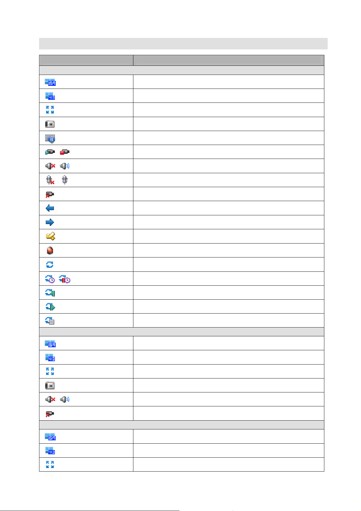
APPENDIX B-TOOLBARS
Application/Version Comelit RAS Solution/from 1.2.0.6
Live1/Live2 View
Wide 16:9 Split Mode (12, 20, 24)
Standard 4:3 Split Mode (1, 4, 7, 9, 13, 16, 21, 25, 33, 36)
Full Screen
Snapshot
Freeze
Manual Record Off/On
Speaker Mute On/Off
Microphone Mute On/Off
Disconnect All Devices
Previous Split Group
Playback View
Next Split Group
Text Message Input
Set/Reset Event Channel
Sequence Mode Status/Off
Sequence Timer On/Off
Previous Sequence View Point
Next Sequence View Point
Sequence View Point List
Wide 16:9 Split Mode (12)
Standard 4:3 Split Mode (1, 4, 7, 9, 13, 16)
Full Screen
Snapshot
Speaker Mute On/Off
Delete All Playback Devices
Emap View
Wide 16:9 Split Mode (12, 20, 24)
Standard 4:3 Split Mode (1, 4, 7, 9, 13, 16, 21, 25, 33, 36)
Full Screen
93
 Loading...