

Page 1
1
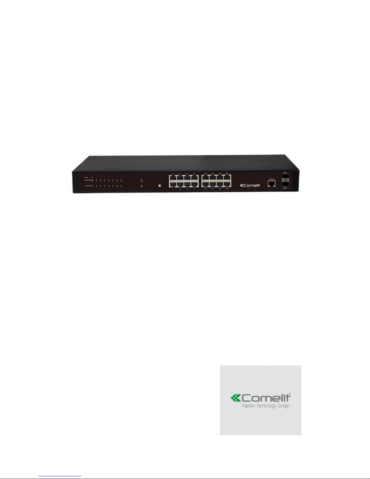
SWITCH, 16 GIGABIT PORTS +
2 SFP PORTS
ART. IPSWC162A
Please read this manual thoroughly before use and keep it for future reference
Page 2

2
Table of Contents
Chapter 1 Product Introduction .................................................................... 4
1.1 Product Overview ................................................................................................... 4
1.2 Features.................................................................................................................. 4
1.3 External Component Description ........................................................................... 4
1.3.1 Front Panel ...................................................................................................................... 4
1.3.2 Rear Panel ...................................................................................................................... 6
1.4 Package Contents .................................................................................................. 6
Chapter 2 Installing and Connecting the Switch ......................................... 7
2.1 Installation............................................................................................................... 7
2.1.1 Desktop Installation ................................................................ ................................ ......... 7
2.1.2 Rack-mountable Installation in 19-inch Cabinet .............................................................. 7
2.1.3 Power on the Switch ........................................................................................................ 8
2.2 Connect Computer (NIC) to the Switch .................................................................. 8
Chapter 3 How to Login the Switch .............................................................. 9
3.1 Switch to End Node ................................................................................................ 9
3.2 How to Login the Switch ......................................................................................... 9
Chapter 4 Switch Configuration ................................................................. 11
4.1 Quickly setting ...................................................................................................... 11
4.2 Port management ................................................................................................. 13
4.2.1 Basic config ................................................................................................................... 14
4.2.2 Port aggregation ............................................................................................................ 15
4.2.3 Port mirroring ................................................................................................................. 17
4.2.4 Port rate-limit ................................................................................................................. 18
4.2.5 Port isolation .................................................................................................................. 19
4.3 VLAN .................................................................................................................... 20
4.3.1 VLAN config .................................................................................................................. 21
4.3.2 Trunk-port setting .......................................................................................................... 22
4.3.3 Hybrid-port setting ................................................................................................ ......... 23
4.4 Fault/Safety .......................................................................................................... 25
4.4.1 Anti attack ...................................................................................................................... 25
4.4.1.1 Anti DHCP attack ............................................................................................... 25
4.4.1.2 Anti DOS ............................................................................................................ 27
4.4.1.3 IP source guard .................................................................................................. 28
4.4.1.4 Anti three bind .................................................................................................... 29
4.4.2 Channel detection ......................................................................................................... 31
4.4.2.1 Ping testing ........................................................................................................ 31
4.4.2.2 Tracert testing .................................................................................................... 32
4.4.2.3 Cable testing ...................................................................................................... 33
4.4.3 ACL ............................................................................................................................... 34
4.5 MSTP .................................................................................................................... 35
4.5.1 MSTP region ................................................................................................................. 36
4.5.2 MSTP bridge ................................................................................................................. 37
Page 3

3
4.6 DHCP relay ........................................................................................................... 40
4.6.1 DHCP relay ................................................................................................................... 40
4.6.2 0ption82......................................................................................................................... 41
4.7 QoS ....................................................................................................................... 43
4.7.1 QoS multi-label .............................................................................................................. 43
4.7.2 Queue config ................................................................................................................. 45
4.7.3 Mapping the queue ................................................................................................ ........ 46
4.7.3.1 Service class queue mapping ............................................................................ 46
4.7.3.2 Differential service class mapping ...................................................................... 47
4.7.3.3 Port to service class mapping ............................................................................ 48
4.8 Address table ........................................................................................................ 49
4.8.1 Mac add and delete ....................................................................................................... 50
4.8.2 Mac study and aging ..................................................................................................... 51
4.8.3 Mac address filtering ..................................................................................................... 52
4.9 Snmp config .......................................................................................................... 53
4.9.1 Snmp config .................................................................................................................. 53
4.9.1.1 Snmp config ................................................................ ....................................... 53
4.9.1.2 Community config .............................................................................................. 54
4.9.1.3 View config ................................................................................................ ......... 55
4.9.1.4 Group config ...................................................................................................... 56
4.9.1.5 User config ......................................................................................................... 57
4.9.1.6 Trap .................................................................................................................... 58
4.9.2 Rmon config .................................................................................................................. 59
4.9.2.1 Statistics group ................................................................................................... 59
4.9.2.2 History group ...................................................................................................... 61
4.9.2.3 Event group ........................................................................................................ 62
4.9.2.4 Alarm group ........................................................................................................ 63
4.10 System ................................................................................................................ 64
4.10.1 System ........................................................................................................................ 65
4.10.1.1 System config .................................................................................................. 65
4.10.1.2 System restart .................................................................................................. 67
4.10.1.3 Password change............................................................................................. 68
4.10.1.4 System log ....................................................................................................... 69
4.10.2 System upgrade .......................................................................................................... 70
4.10.3 Config management .................................................................................................... 71
4.10.3.1 Current configuration ........................................................................................ 71
4.10.3.2 Configuration backup ....................................................................................... 73
4.10.3.3 Restore factory configuration ........................................................................... 74
4.10.4 Config save ................................................................................................................. 75
4.10.5 Administrator privileges ............................................................................................... 75
4.10.6 Info collect ................................................................................................................... 76
Appendix: Technical Specifications ................................................................ 78
Page 4

4
Chapter 1 Product Introduction
Congratulations on your purchasing of the Web Smart Ethernet Switch. Before you install
and use this product, please read this manual carefully for full exploiting the functions of
this product.
1.1 Product Overview
This is a Web Smart Ethernet Switch with 16-10/100/1000Mbps Auto-Negotiation RJ45
ports +2-SPF ports. All UTP ports support Auto MDI/MDIX function. The Switch provides
the seamless network connection, which integrates 1000Mbps Gigabit Ethernet, 100Mbps
Fast Ethernet and 10Mbps Ethernet network capabilities in a highly flexible package.
The Web Smart Ethernet Switch can be configured by web based interface. Including
administrator, port management, VLAN setting, each port statistics, STP setting, QoS
setting, security filter, configuration/ backup/recovery, log out, and so on.
This Switch has the easy-to-use and high performance qualities.
1.2 Features
Comply with IEEE 802.3, IEEE 802.3u, IEEE 802.3ab, IEEE 802.3x, IEEE 802.3z,
IEEE 802.3ad standards
Supports IEEE 802.3x flow control for Full-duplex mode and backpressure for
Half-duplex mode
Supports MAC address auto-learning and auto-aging
Operates in store and forward mode
Support SNMP/RMON/TELNET
Supports IEEE 802.1q VLAN, 4K VLAN Table
Support IEEE 802.1p Priority Queues
Support ACL Function, 1.5K-entry ALC table
Support Storm Control
Support QoS, Port Mirroring, Link Aggregation Protocol
LED indicators for monitoring power, link/activity
Support web-based Management
Internal power adapter supply
1.3 External Component Description
1.3.1 Front Panel
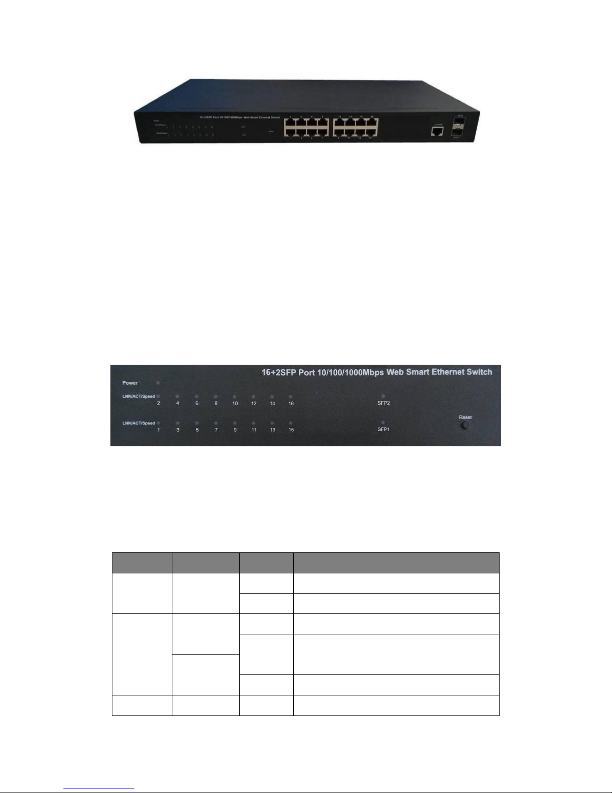
The front panel of the Switch consists of 16 x 10/100/1000Mbps RJ-45 ports, 2 x SFP
ports, 1 x Console port, 1 x Reset button and a series of LED indicators as shown as
below.
Page 5
5
Figure 1 - Front Panel
10/100/1000Mbps RJ-45 ports (1~16):
Designed to connect with the device with a bandwidth of 10Mbps, 100Mbps or 1000Mbps.
Each has a corresponding 10/100/1000Mbps LED.
SFP ports (SFP1, SFP2):
Designed to install the SFP module and connect to the device with a bandwidth of
1000Mbps. Each has a corresponding 1000Mbps LED.
Console port (Console):
Designed to connect with the serial port of a computer or terminal for monitoring and
configuring the switch.
Reset button (Reset):
Keep the device powered ON and press down the button for about 5 seconds. The system
restores the factory default settings.
LED indicators:
Figure 2 - LED Indicators
The LED Indicators will allow you to monitor, diagnose and troubleshoot any potential
problem with the Switch, connection or attached devices.
The following chart shows the LED indicators of the Switch along with explanation of each
indicator.
LED
COLOR
STATUS
STATUS DESCRIPTION
Power
Red
On
Power ON
Off
Power OFF
LNK/ACT/
Speed
(1~16)
10/100Mbps:
Orange
On
A device is connected to the port
Off
A device is disconnected to the port
1000Mbps:
Green
Flashing
Sending or receiving data
SFP1
Green
On
A device is connected to the port
Page 6
6
SFP2
Off
A device is disconnected to the port
Flashing
Sending or receiving data
1.3.2 Rear Panel
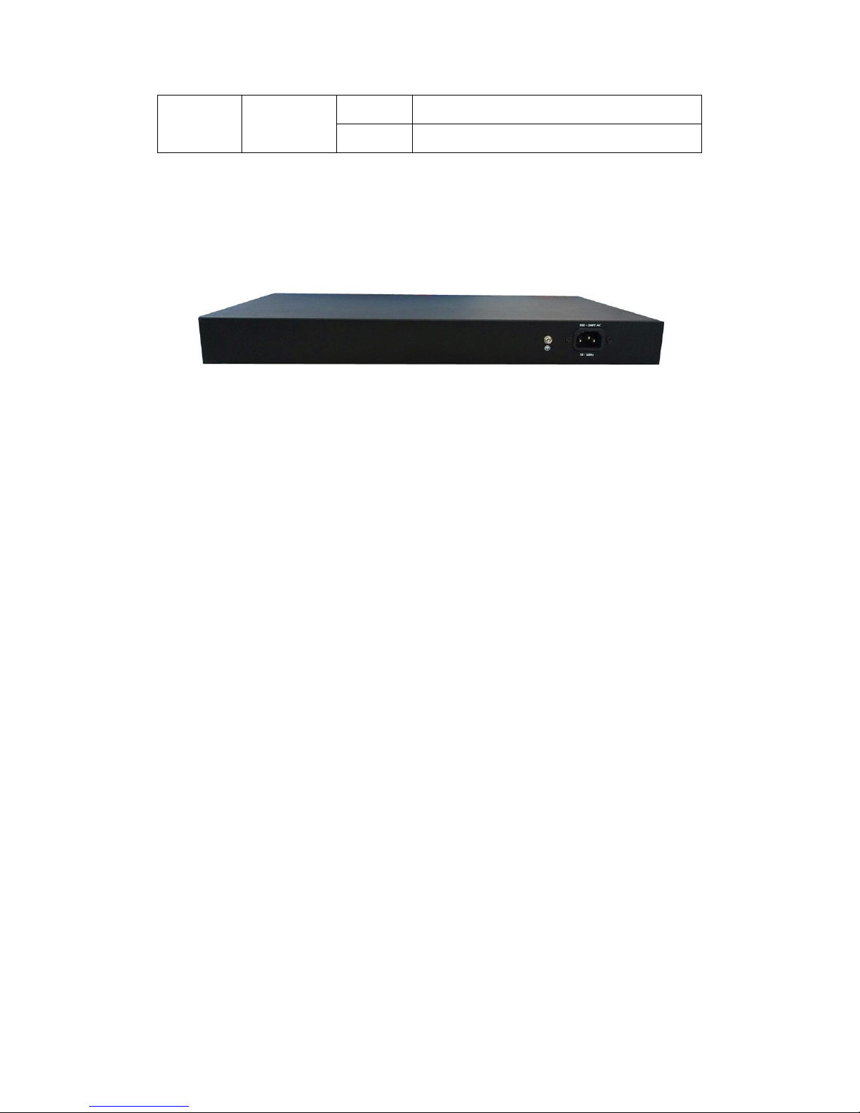
The rear panel of the Switch contains AC power connector and one marker shown as
below.
Figure 3 - Rear Panel
AC Power Connector:
Power is supplied through an external AC power adapter. It
supports AC 100~240V,
50~60Hz.
Grounding Terminal:
The switch already comes with Lightning Protection Mechanism. You can also ground
the switch through the PE (Protecting Earth) cable of AC cord or with Ground Cable.
1.4 Package Contents
Before installing the switch, make sure that the following the "packing list" listed OK. If any
part is lost and damaged, please contact your local agent immediately. In addition, make
sure that you have the tools to install switche and cables in your hands.
One Web Smart Ethernet Switch
Four rubber feet, two mounting ears and eights screws
One AC power cord
One User Manual
Page 7
7
Chapter 2 Installing and Connecting the Switch
This part describes how to install your Web Smart Ethernet Switch and make connections
to it. Please read the following topics and perform the procedures in the order being
presented.
2.1 Installation
Please follow the following instructions in avoid of incorrect installation causing device
damage and security threat.
Put the Switch on stable place or desktop in case of falling damage.
Make sure the Switch works in the proper AC input range and matches the voltage
labeled on the Switch.
To keep the Switch free from lightning, do not open the Switch’s shell even in power
failure.
Make sure that there is proper heat dissipation from and adequate ventilation around
the Switch.
Make sure the cabinet to enough back up the weight of the Switch and its
accessories.
2.1.1 Desktop Installation
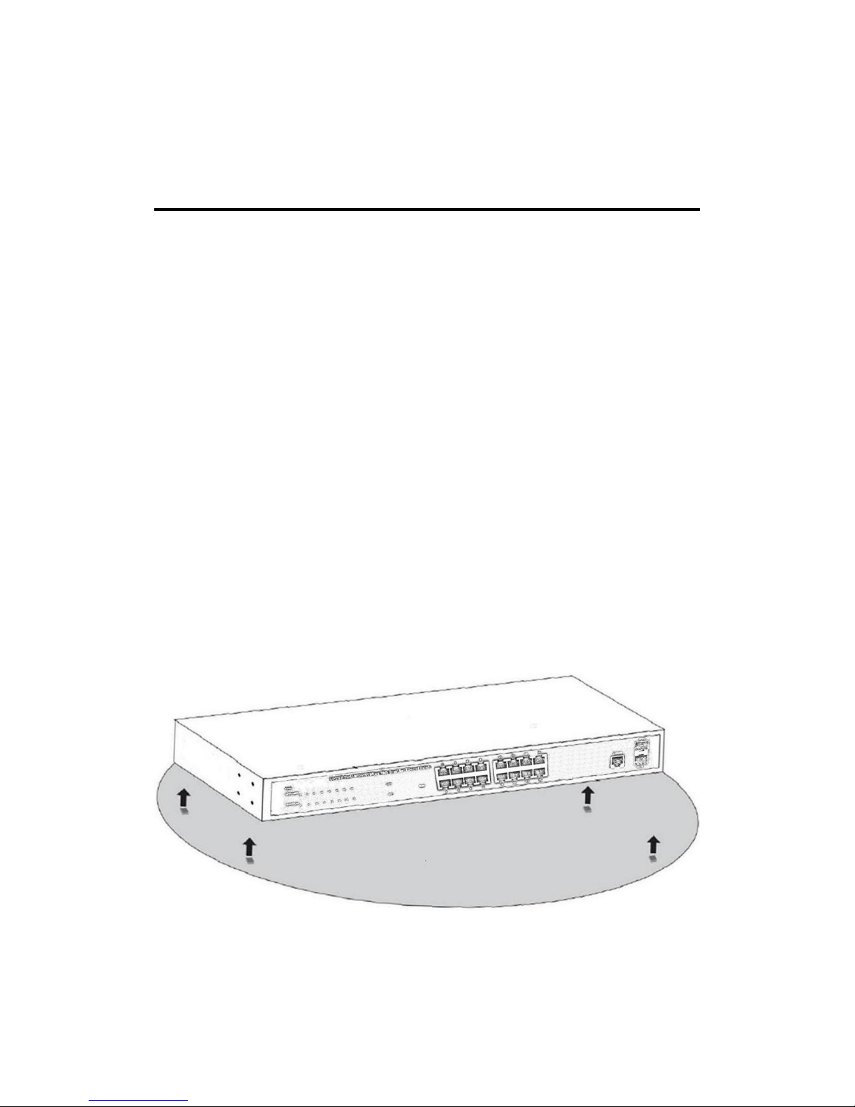
Sometimes users are not equipped with the 19-inch standard cabinet. So when installing
the Switch on a desktop, please attach these cushioning rubber feet provided on the
bottom at each corner of the Switch in case of the external vibration. Allow adequate
space for ventilation between the device and the objects around it.
Figure 4 - Desktop Installation
2.1.2 Rack-mountable Installation in 19-inch Cabinet
The Switch can be mounted in an EIA standard-sized, 19-inch rack, which can be placed
Page 8
8
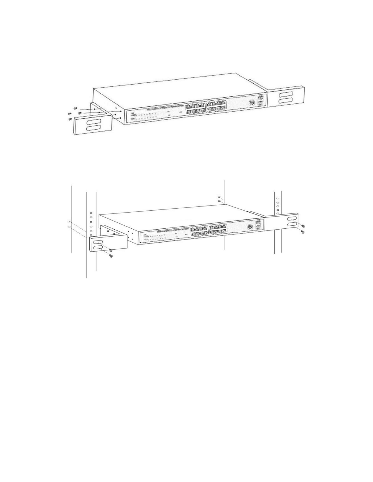
in a wiring closet with other equipment. To install the Switch, please follow these steps:
a. Attach the mounting brackets on the Switch’s side panels (one on each side) and
secure them with the screws provided.
Figure 5 - Bracket Installation
b. Use the screws provided with the equipment rack to mount the Switch on the rack
and tighten it.
Figure 6 - Rack Installation
2.1.3 Power ON the Switch
The Switch is powered on by the AC 100-240V 50/60Hz internal high-performance power
supply. Please follow the next tips to connect:
AC Electrical Outlet:
It is recommended to use single-phase three-wire receptacle with neutral outlet or
multifunctional computer professional receptacle. Please make sure to connect the metal
ground connector to the grounding source on the outlet.
AC Power Cord Connection:
Connect the AC power connector in the back panel of the Switch to external receptacle
with the included power cord and check the power indicator is ON or not. When it is ON, it
indicates the power connection is OK.
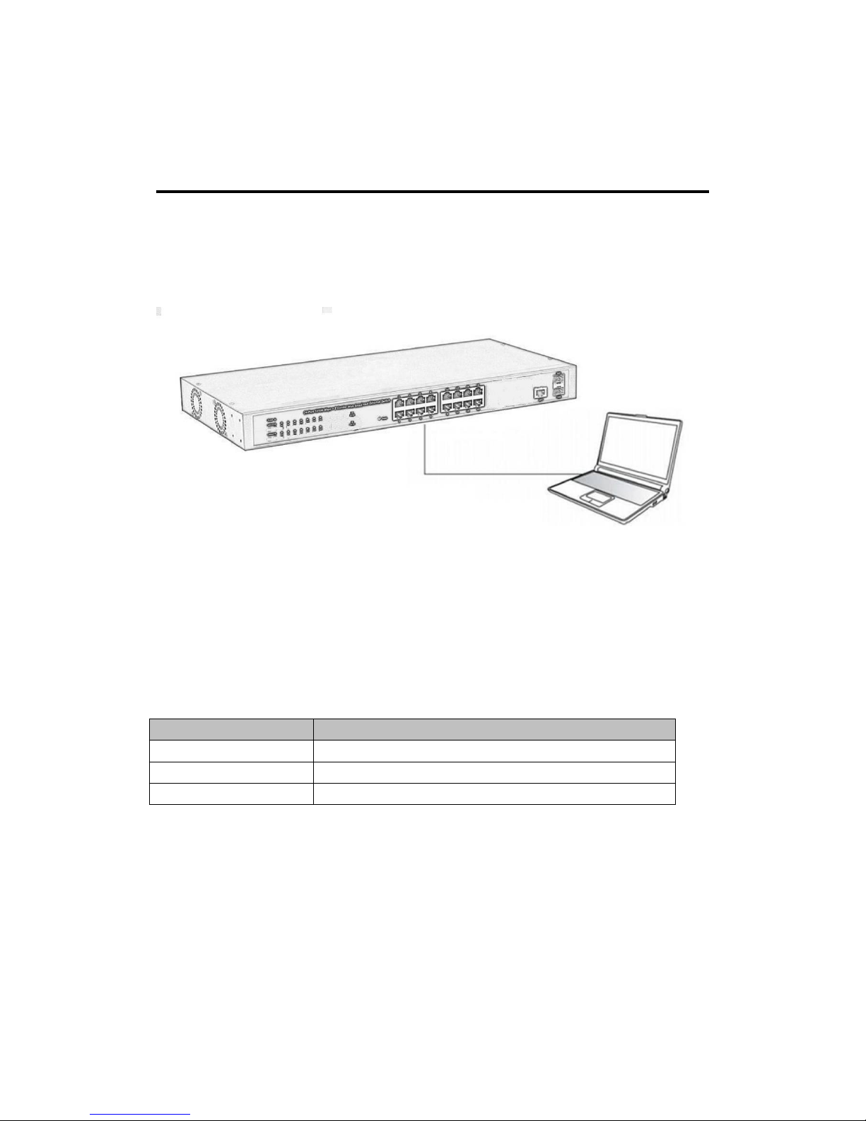
2.2 Connect Computer (NIC) to the Switch
Please insert the NIC into the computer, after installing network card driver, please
connect one end of the twisted pair to RJ-45 jack of your computer, the other end will be
Page 9
9
connected to any RJ-45 port of the Switch, the distance between Switch and computer is
around 100 meters. Once the connection is OK and the devices are power on normally,
the LINK/ACT/Speed status indicator lights corresponding ports of the Switch.
Chapter 3 How to Login the Switch
3.1 Switch to End Node
Use standard Cat.5/5e Ethernet cable (UTP/STP) to connect the Switch to end nodes as
described below. Switch ports will automatically adjust to the characteristics (MDI/MDI-X,
speed, duplex) of the device to which is connected.
Figure 7 - PC Connect
Please refer to the LED Indicator Specification.The LINK/ACT/Speed LEDs for each port
lights on when the link is available.
3.2 How to Login the Switch
As the Switch provides Web-based management login, you can configure your computer’s
IP address manually to log on to the Switch. The default settings of the Switch are shown
below.
Parameter
Default Value
Default IP address
192.168.2.1
Default Username
admin
Default Password
admin
You can log on to the configuration window of the Switch through following steps:
1. Connect the Switch with the computer NIC interface.
2. Power on the Switch.
3. Check whether the IP address of the computer is within this network segment:
192.168.2.xxx (“xxx” ranges 2~254), for example, 192.168.2.100.
4. Open the browser, and enter http://192.168.2.1 and then press “Enter”. The Switch
login window appears, the following picture:
Page 10

10
5. Enter the Username and Password (the factory default Username is admin and
Password is admin), and then click “login” to log in to the Switch configuration window as
below. Need to click on the upper right corner of the "Language" switch to change
language between English and Chinese.
Page 11
11
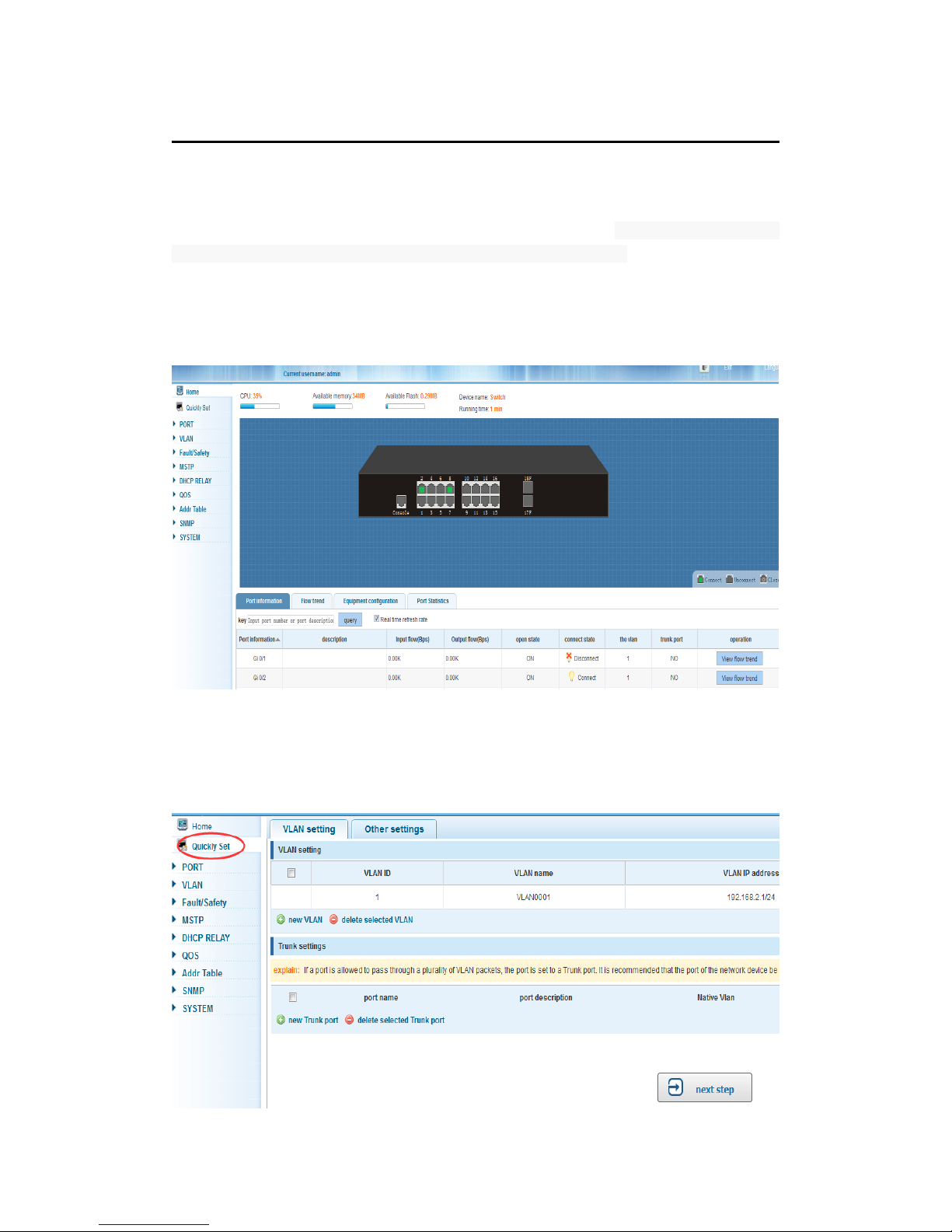
Chapter 4 Switch Configuration
The Web Smart Ethernet Switch Managed switch software provides rich layer 2
functionality for switches in your networks. This chapter describes how to use Web-based
management interface (Web UI) to configure this managed switch.
In the Web UI, the left column shows the configuration menu. Above you can see the
information for switch system, such as memory, software version. The middle shows the
switch’s current link status. Green squares indicate the port link is up, while black squares
indicate the port link is down. Below the switch panel, you can find a common toolbar to
provide useful functions for users. The rest of the screen area displays the configuration
settings.
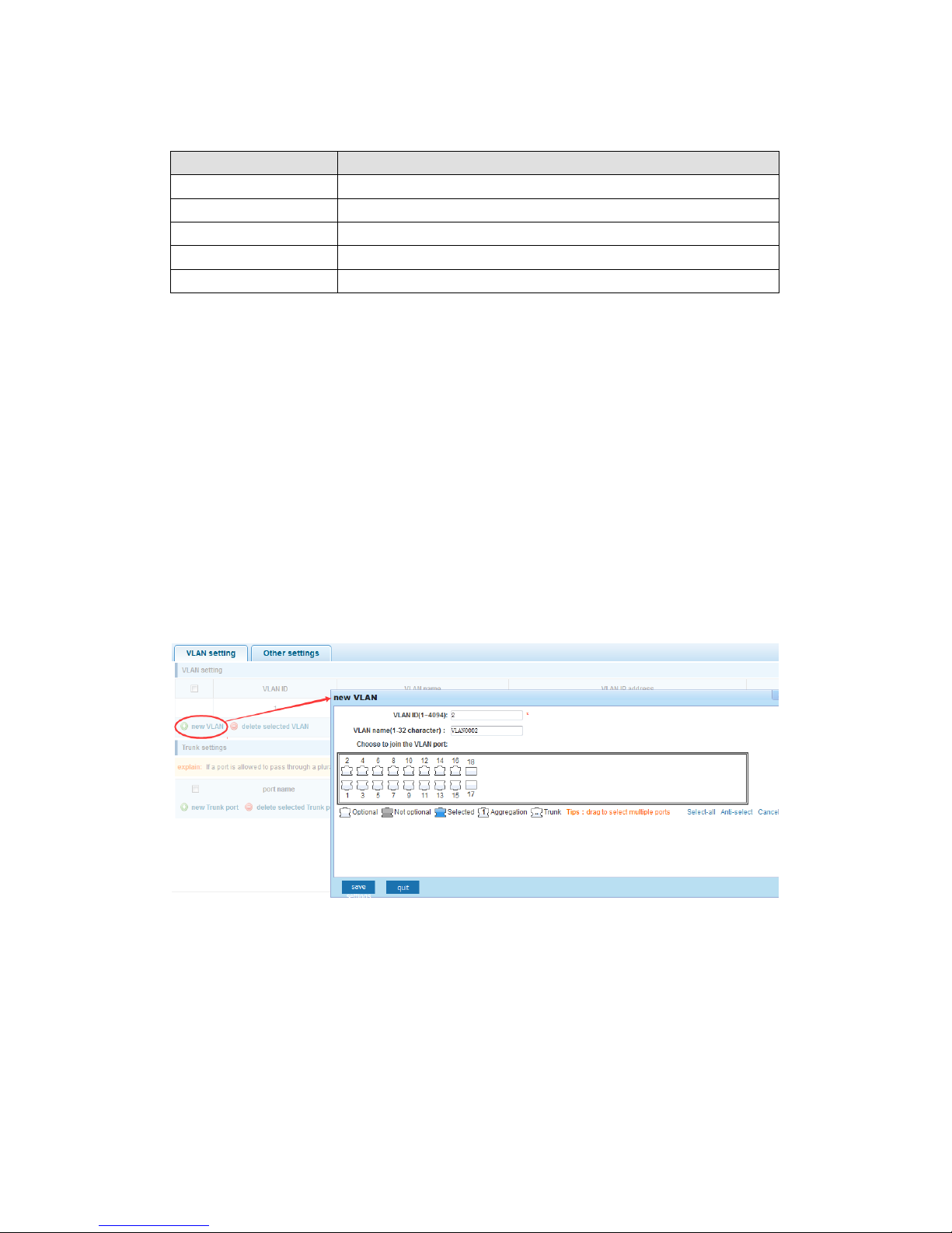
4.1 Quickly setting
In the navigation bar select. “Quickly Set”. Is possible to create a VLAN in this module,
add the port in the VLAN, set the basic information and modify the switch login password.
As the following picture:
Page 12
12
【Parameter Description】
Parameter
Description
VLAN ID
VLAN number,16GE default VLAN 1
VLAN name
VLAN mark
Manage IP
Manage the IP address of the VLAN
device name
Switch name
Manage VLAN
Switches management in use of the VLAN
【Instructions】
Native VLAN: As a Trunk, the mouth will belong to a Native VLAN. The so-called Native
VLAN, is refers to UNTAG send or receive a message on the interface, is considered
belongs to the VLAN. Obviously, the interface of the default VLAN ID (PVID) in the IEEE
802.1Q VLAN ID is the Native VLAN. At the same time, send belong to Native VLAN
frame on the Trunk, must adopt UNTAG way.
Allowed VLAN List: A Trunk can transport all the VLAN traffic (1-4094) supported by the
equipment by default. But, also can be setting the permission VLAN Trunk at the mouth of
the list to limit the flow of some VLAN can't through the Trunk.
【Configuration Example】
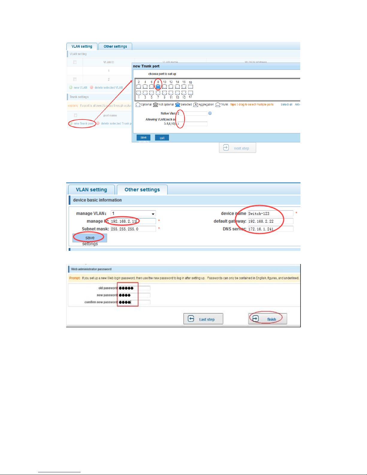
1)VLAN setting: such as create VLAN 2 ,Sets the port 8 to Trunk ,Native VLAN 2
Page 13
13
2) Click ”next step” button, into "Other settings" task: manage IP address set as
192.168.2.11, device name set as switch-123, default gateway with the DNS server set as
172.16.1.241
3) Use 192.168.2.11 to log in, set a new password
4.2 Port management
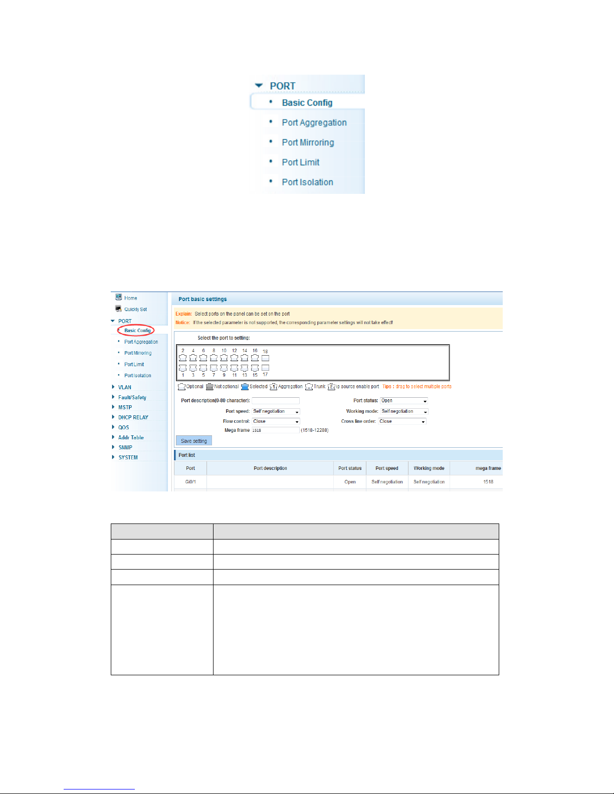
In the navigation bar to select “Port Management”, you may conduct Basic Config, Port
Aggregation, Port Mirroring, Port Limit and Port Isolation.
Page 14
14
4.2.1 Basic config
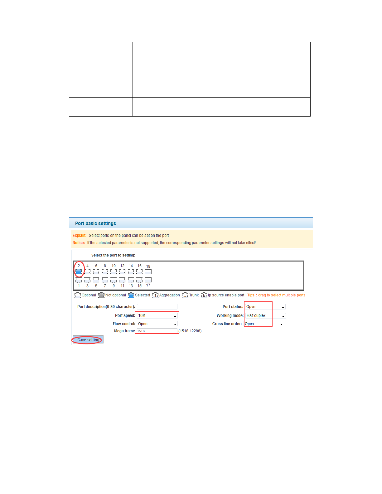
In the navigation bar select “PORT>Basic Config”, for port panel: set port description,
port speed, port status, working mode, flow control, cross line order, mega frame
configuration, as the following picture:
【Parameter Description】
Parameter
Description
port
Select the current configuration port number
port status
Choose whether to close link port
flow control
Whether open flow control
port speed
Can choose the following kinds:
Aggregation
10 M
100 M
1000 M
Page 15
15
working mode
Can choose the following kinds:
Auto negotiated
10 M
100 M
1000 M
port described
The port is described
jumbo frame
Set the length of a jumbo frames ,range 1518-12288
Cross line sequence
Whether open intersection line sequence
【Instructions】
In flow control You can close negotiated. Close negotiated is to set port speed rate and
working mode to other value. Setting the port rate more than actual rate of port will lead
the port disconnect.
【Configuration Example】
Such as: The port is set to 10 M, half duplex, open flow control, cross line sequence and
port state
4.2.2 Port aggregation
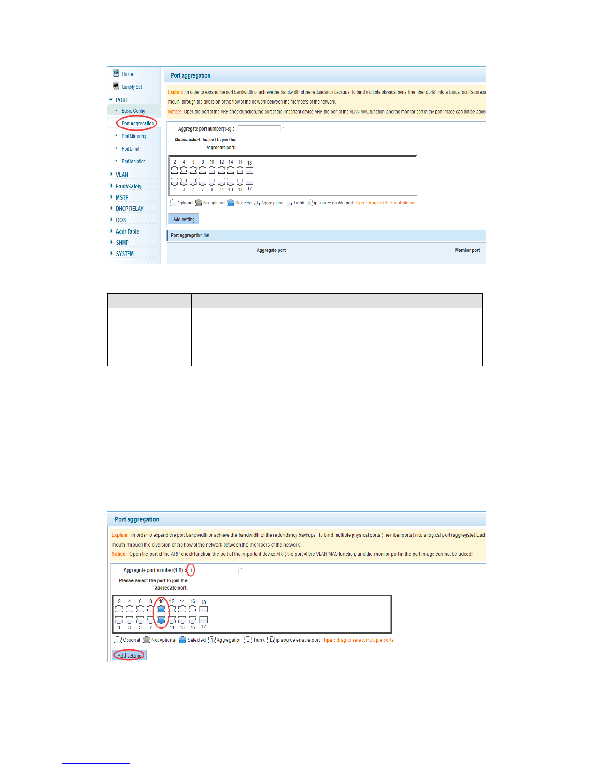
In the navigation bar select “PORT>Port Aggregation”, in order to expand the port
bandwidth or achieve the bandwidth of the redundancy backup, as the following picture:
Page 16
16
【Parameter Description】
Parameter
Description
Aggregation port
16GE switch can be set up eight link trunk group, group_1 to
group_8
Member port
For each of the members of the group and add your own port, and
with members of other groups
【Instructions】
Open the port of the ARP check function, the port of the important device ARP, the port of
the VLAN MAC function and the monitor port in the port image cannot be added.
【Configuration Example】
Such as: set the port 9, 10, for aggregation port 1, lets this aggregation port 1 connected
to other switch aggregation port 1 to build switch links .
Page 17
17
4.2.3 Port mirroring
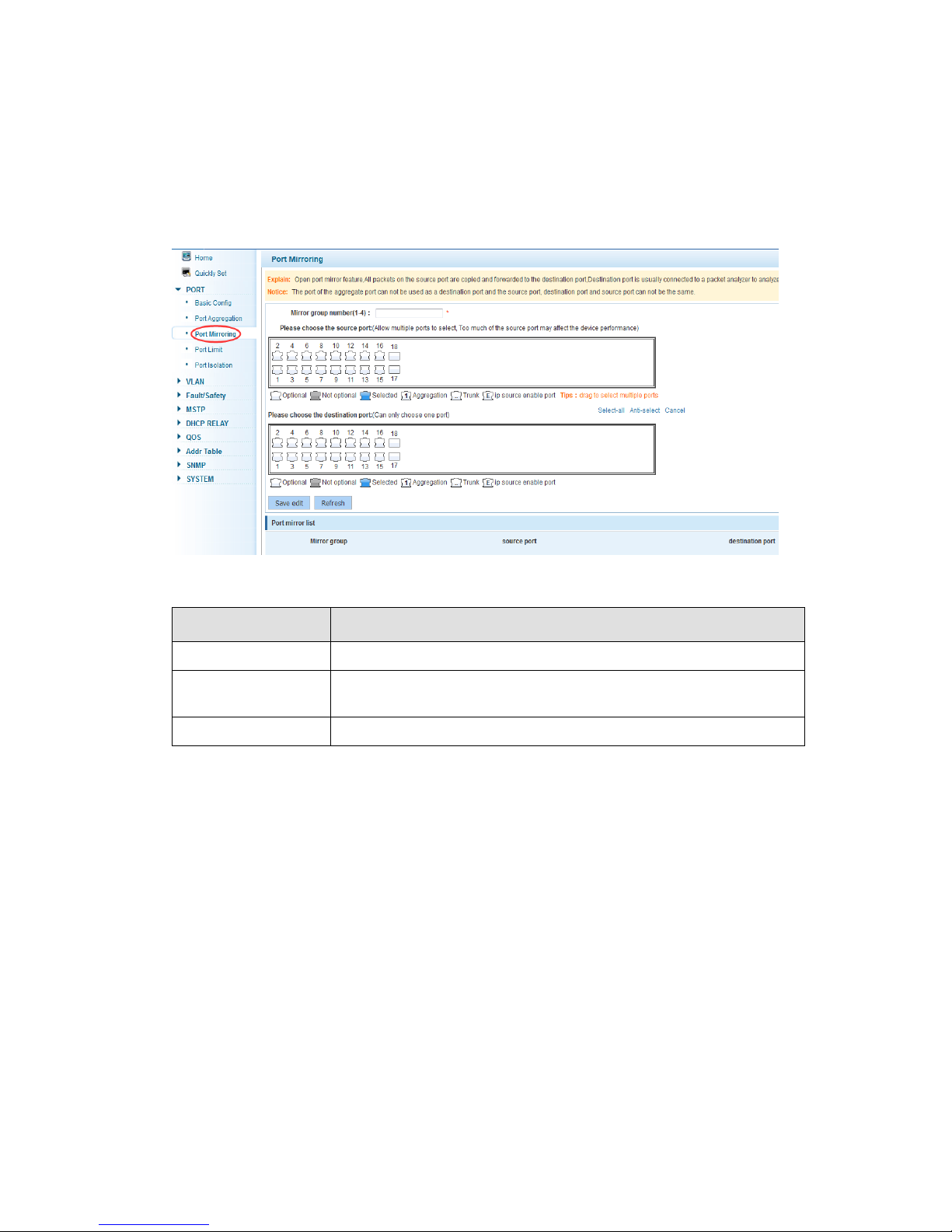
In the navigation bar select “PORT>Port Mirroring”, open port mirror feature. All packets
on the source port are copied and forwarded to the destination port. Destination port is
usually connected to a packet analyzer to analyze the source port. Multiple ports can be
mirrored to a destination port, as the following picture:
【Parameter Description】
Parameter
Description
Source port
To monitor the flow port in and out
Destination port
Set destination port. All packets on the source port are copied and
forwarded to the destination port
Mirror group
Range :1-4
【Instructions】
The port of the aggregate port can’t be used as a destination port and the source port,
destination port and source port can’t be the same.
【Configuration Example】
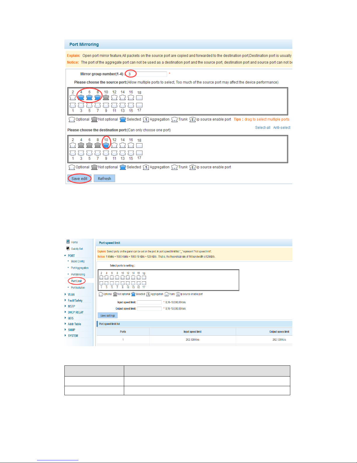
Such as: set a mirror group for port 10 regulatory port 4, 6, 8 in and out flow conditions
Page 18
18
4.2.4 Port rate-limit
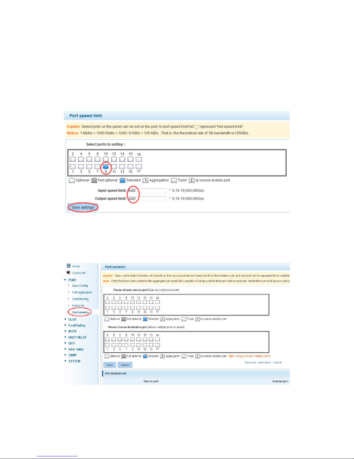
In the navigation bar select “Port>Port Limit”, to configure output, input speed limit, as
the following picture:
【Parameter Description】
Parameter
Description
Input speed limit
Set port input speed
Output speed limit
Set port output speed
Page 19
19
【Instructions】
1 Mbit/s = 1000 Kbit/s = 1000 / 8 KB/s = 125 KB/s. So, the theoretical rate of 1Mbit/s
bandwidth is 125KB/s.
【Configuration Example】
Such as: the port 9 input rate is set to 6400 KB/s, the output rate is set to 3200 KB/s
4.2.5 Port isolation
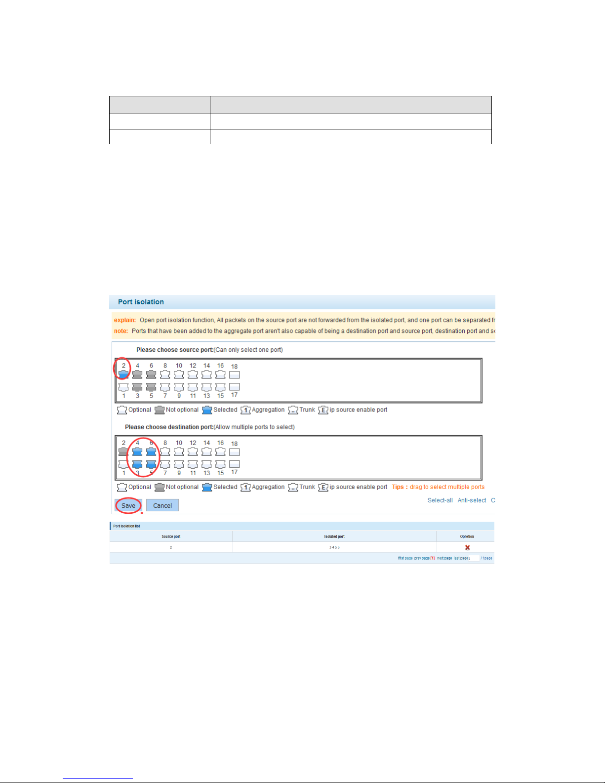
In the navigation bar select “PORT>Port Isolation”, one port can be isolated to one or
multiple destination ports. As the following picture:
Page 20
20
【Parameter Description】
Parameter
Description
Source port
Choose a port, to configure the isolated port
Isolated port
Port will be isolated
【Instructions】
Open port isolation function, all packets on the source port are not forwarded from the
isolated port and one port can be separated from multiple destination ports.
Ports that have been added to the aggregate port aren't capable of being a destination
port and source port, destination port and source port cannot be the same
【Configuration Example】
Such as: the source port 2, isolated port 3, 4, 5, and 6
After the success of the configuration, given out by the port 2 package can't in 3/4/5/6 port
forwarding, but 3/4/5/6 ports issued a message can be forwarded on port 2, if you need
not forwarding should be carried out respectively on the 3/4/5/6 port configuration.
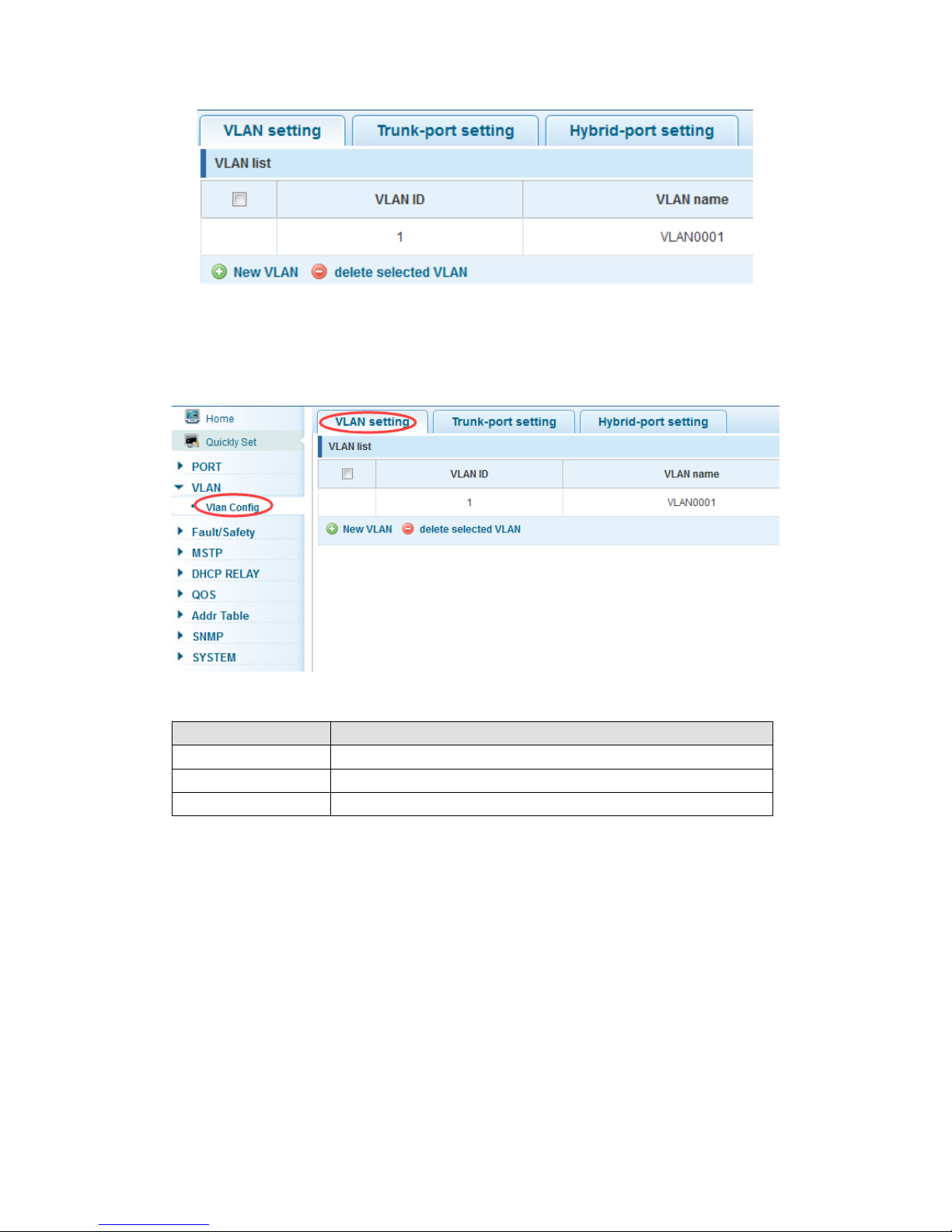
4.3 VLAN
In the navigation bar select “VLAN”, you can manage the VLAN setting, Trunk –port
Settings and Hybrid-port Settings, as the following picture:
Page 21
21
4.3.1 VLAN config
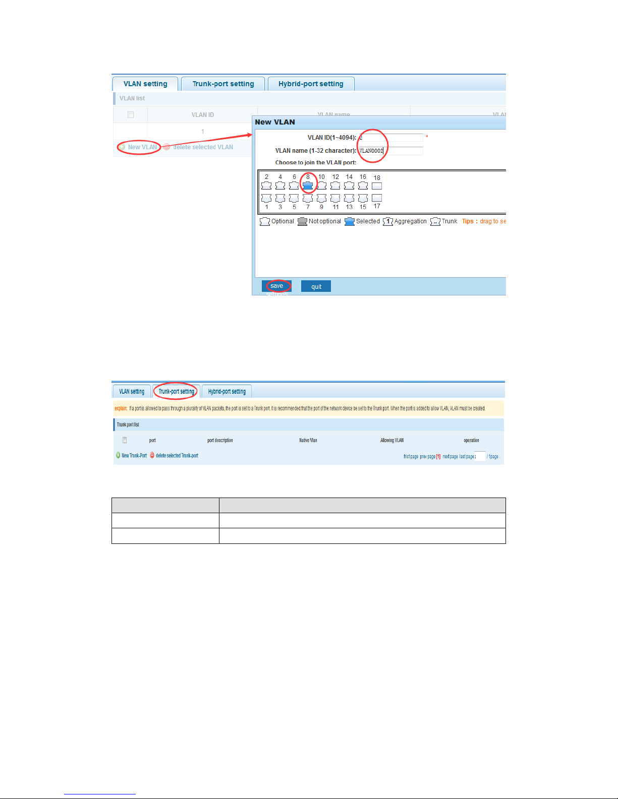
In the navigation bar select “Vlan Config”, VLANs can be created and set the port to the
VLAN (port default state for the access mode) ,the following picture:
【Parameter Description】
Parameter
Description
VLAN ID
VLAN number,16GE default VLAN 1
VLAN name
VLAN mark
VLAN IP address
Manage switch IP address
【Instructions】
Management VLAN, the default VLAN cannot be deleted. Add ports to access port, port
access mode can only be a member of the VLAN.
【Configuration Example】
Such as: connect switches pc1, pc2 couldn't ping each other, will be one of the PC
connection port belongs to a VLAN 2
Page 22
22
4.3.2 Trunk-port setting
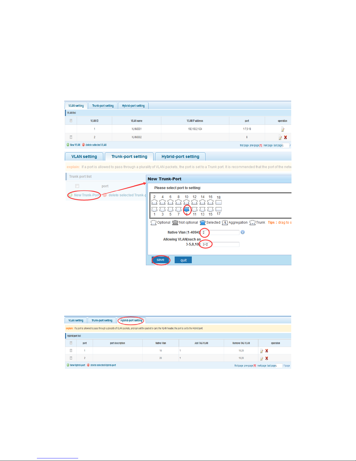
In the navigation bar select “Vlan Config>Trunk-port setting”, can set port to Trunk port,
as the following picture:
【Parameter Description】
Parameter
Description
Native VLAN
Only set one
Allowing VLAN
Can set up multiple
【Instructions】
Native VLAN: As a Trunk, the mouth will belong to a Native VLAN. The so-called Native
VLAN, is refers to UNTAG send or receive a message on the interface, is considered
belongs to the VLAN. Obviously, the interface of the default VLAN ID (PVID) in the IEEE
802.1Q VLAN ID is the Native VLAN. At the same time, send belong to Native VLAN
frame on the Trunk, must adopt UNTAG way.
Allowed VLAN List: A Trunk can transport all the VLAN traffic (1-4094) supported by the
equipment by default. But, also can be setting the permission VLAN Trunk at the mouth of
the list to limit the flow of some VLAN can't through the Trunk
Page 23
23
【Configuration Example】
Such as: PVID=VLAN2
PC1:192.168.2.122, port 8, access VLAN2
PC2:192.168.2.123, port 9, Trunk allowed VLAN 1-2
PC3:192.168.2.124, port 10, access VLAN1 (the default port belongs to VLAN1)
Can let the PC2 PING PC1, cannot PING PC3
4.3.3 Hybrid-port setting
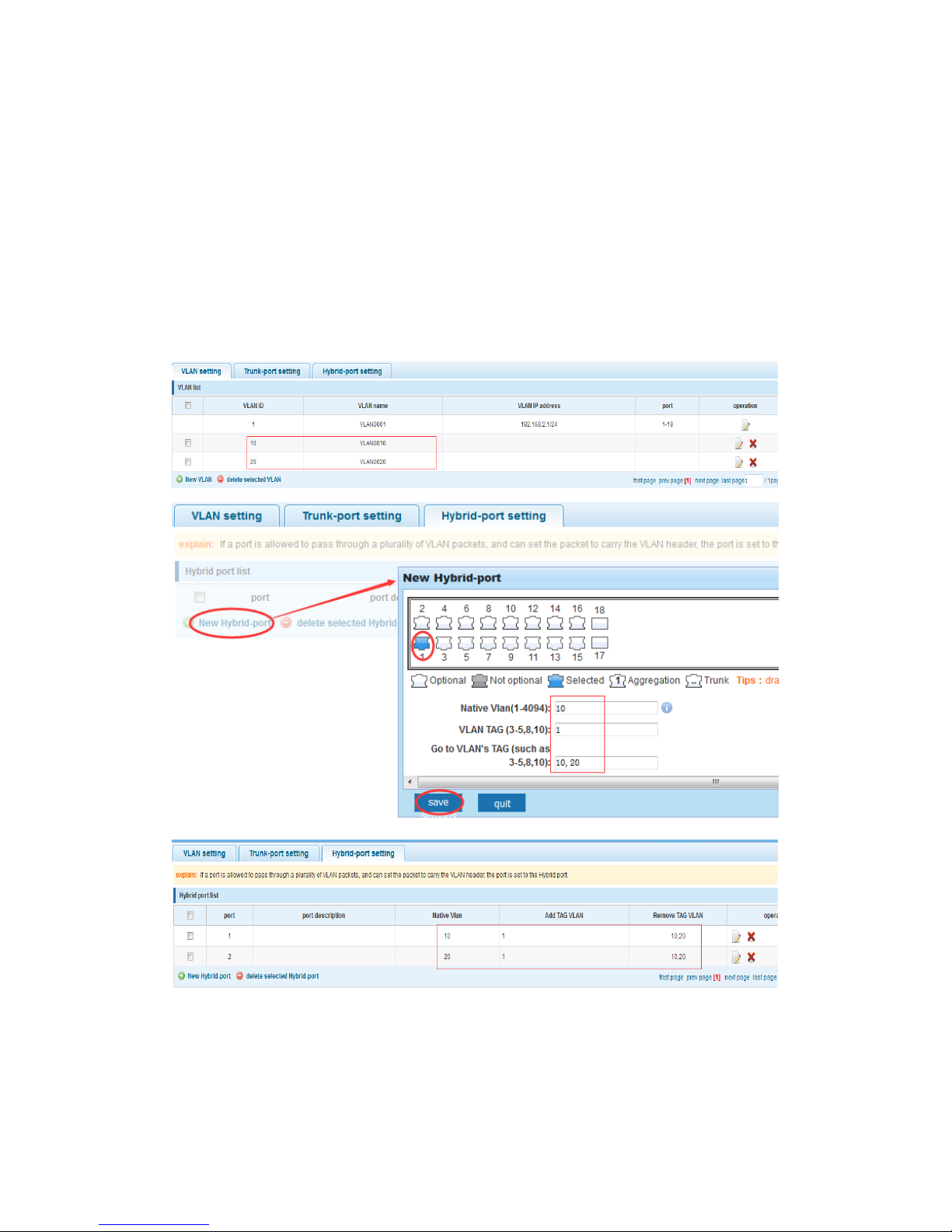
In the navigation bar select “Vlan Config>Hybrid-port setting”, can set the port to take
the tag and without the tag, as the following picture:
【Instructions】
Hybrid port to packet:
Receives a packet, judge whether there is a VLAN information: if there is no play in port
PVID, exchanged and forwarding, if have, whether the Hybrid port allows the VLAN data
Page 24
24
into: if can be forwarded, or discarded (untag on port configuration is not considered,
untag configuration only work when to send it a message)
Hybrid port to send packet:
1, determine the VLAN in this port attributes (display interface can show the port to which
VLAN untag, which VLAN tag)
2, if it is untag stripping VLAN information, send again, if the tag is sent directly
【Configuration Example】
Such as: create VLANs 10, 20, VLAN sets the Native VLAN port 1 to 10, to tag VLAN for
10, 20, sets the Native VLAN port 2 to 20, to tag VLAN for 10, 20
This system e0/1 and the receive system e0/2 PC can be exchanged, but when each data
taken from a VLAN is different.
Data from the pc1, by inter0/1 PVID VLAN10 encapsulation VLAN10 labeled into switches,
switch found system e0/2 allows 10 data through the VLAN, so the data is forwarded to
the system e0/2, because the system e0/2 VLAN is untagged 10, then switches at this
Page 25
25
time to remove packet VLAN10 tag, in the form of ordinary package sent to pc2, pc1 - > p2
is VLAN10 walking at this time
Again to analyze pc2 gave pc1 package process, data from the pc2, by inter0/2 PVID
VLAN20 encapsulation VLAN20 labeled into switch, switch found system e0/1 allows
VLAN by 20 data, so the data is forwarded to the system e0/1, because the system e0/1
on the VLAN is untagged 20, then switches remove packets on VLAN20 tag at this time, in
the form of ordinary package sent to pc1, pc2 at this time - > pc1 is VLAN 20
4.4 Fault/Safety
In the navigation bar select “Fault/Safety”, you can set Anti Attack, Channel Detection
and ACL Access Control configuration.
4.4.1 Anti attack
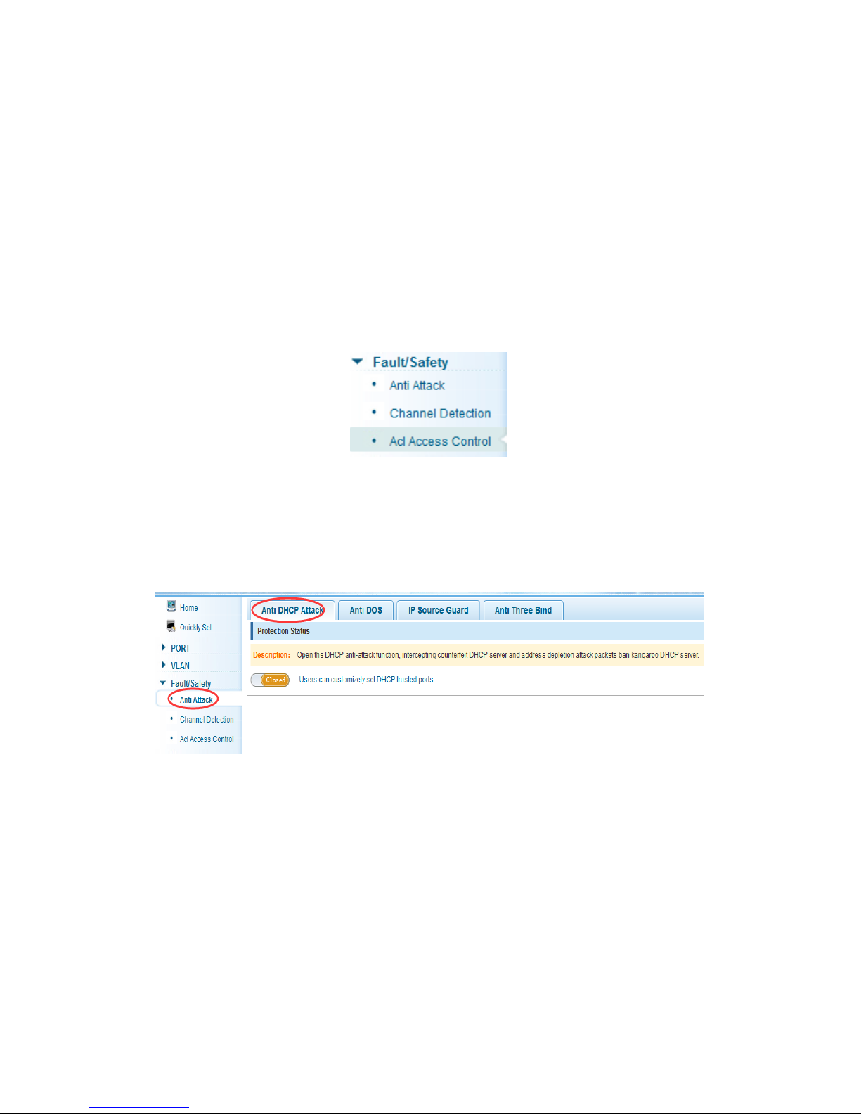
4.4.1.1 Anti DHCP attack
In the navigation bar select “Fault/Safety>Anti Attack>Anti DHCP Attack”, open the
DHCP anti-attack function, intercepting counterfeit DHCP server and address attack
packets ban kangaroo DHCP server, as the following picture:
【Instructions】
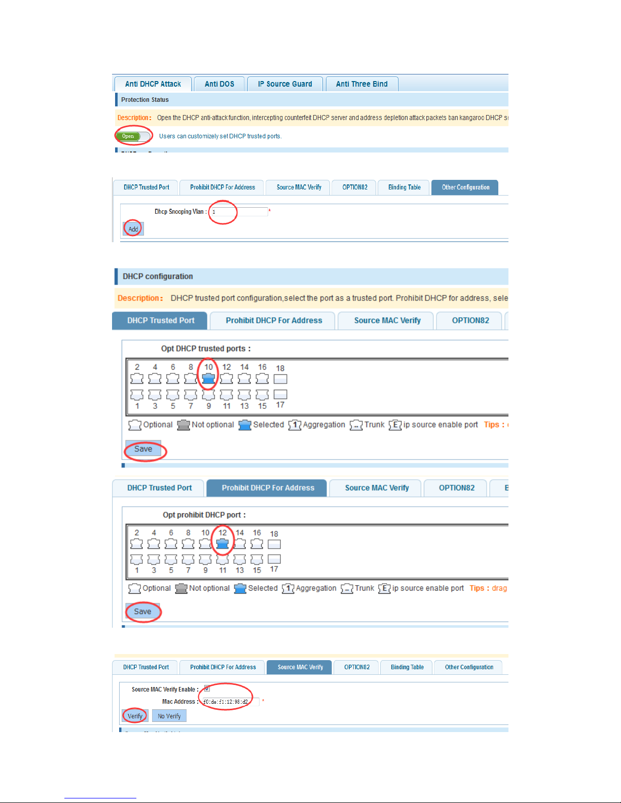
DHCP trusted port configuration, select the port as a trusted port. Prohibit DHCP for
address, select the port and save, you can disable this feature for the port.
Open DHCP attack prevention function, need to set the DHCP protective VLAN
simultaneously, other functions to take effect.
【Configuration Example】
Such as: 1.dhcp snooping open
Page 26
26
2.Setting DHCP snooping VLAN
Set the connection router 10 ports for trust, then 12 port is set to the prohibit
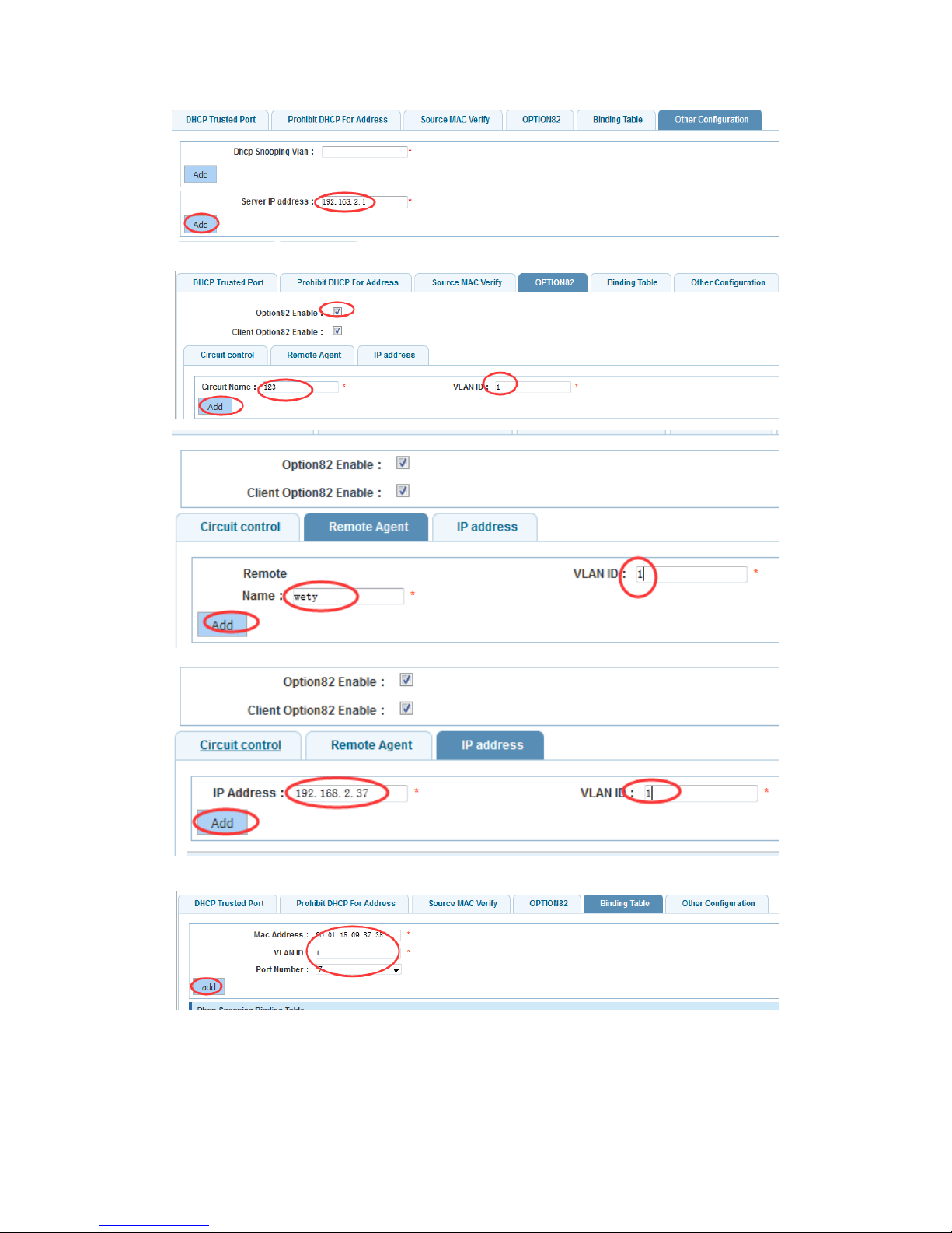
3.Verify source mac F0:DE:F1:12:98:D2,set server IP address to 192.168.2.1
Page 27
27
4.Set option82 information
5.The port 7 for binding
4.4.1.2 Anti DOS
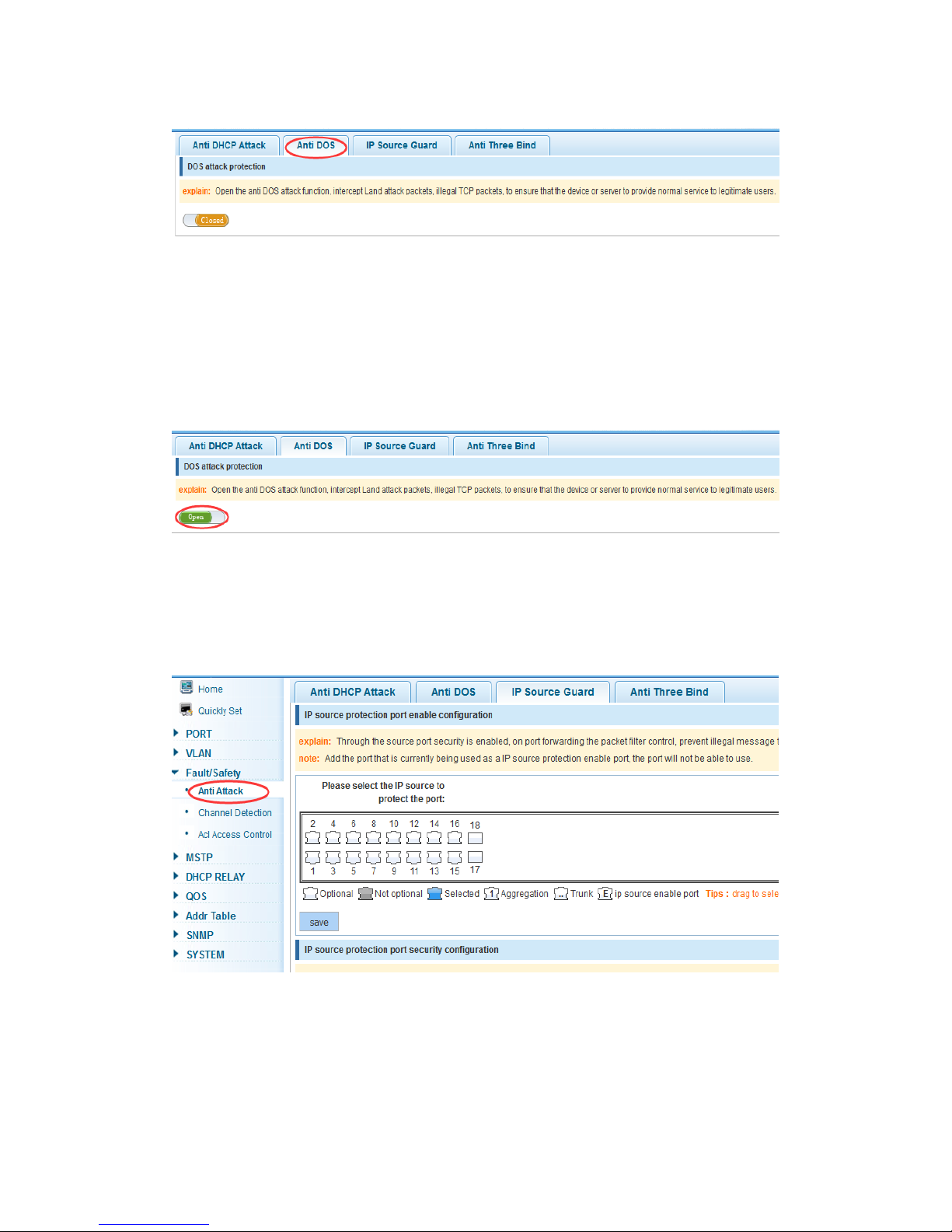
In the navigation bar select “Fault/Safety>Anti Attack>Anti DOS”, open the Anti DOS
attack function, intercept Land attack packets, illegal TCP packets, to ensure that the
Page 28
28
device or server to provide normal service to legitimate users, as the following picture:
【Instructions】
Open the anti DOS attack function, intercept Land attack packets, illegal TCP packets, to
ensure that the device or server provide normal service to legitimate users.
【Configuration Example】
Such as: Open the anti DOS attack function
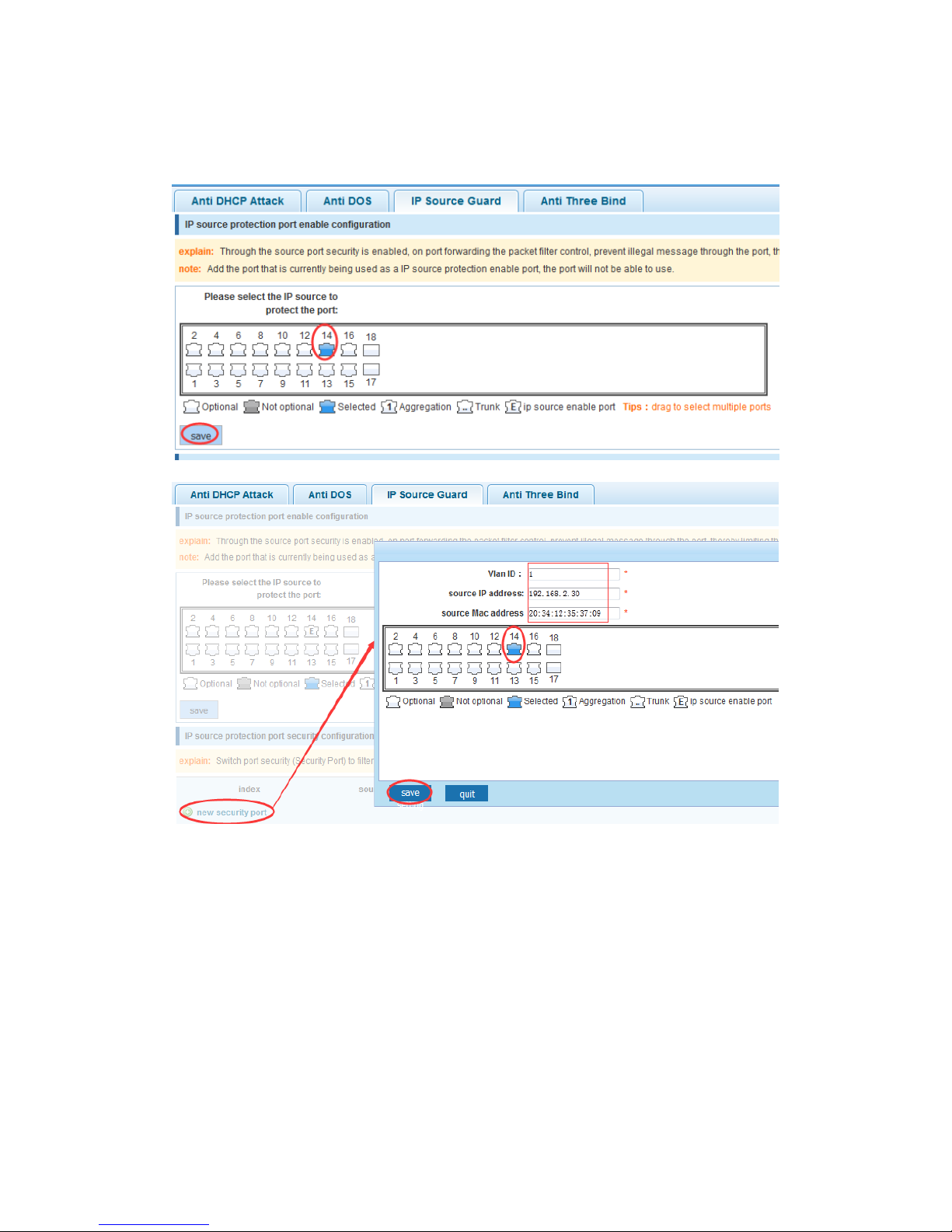
4.4.1.3 IP source guard
In the navigation bar select “Fault/Safety>Anti Attack>IP Source Guard”, through the
source port security enabled, on port forwarding the packet filter control, prevent illegal
message through the port, thereby limiting the illegal use of network resources, improve
the safety of the port, as the following picture:
【Instructions】
Add the port that is currently being used as an IP source protection enable port, the port
will not be able to use.
Page 29
29
【Configuration Example】
Such as: to open source IP protection enabled port first, then to binding
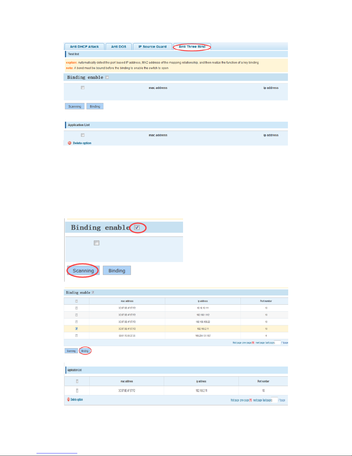
4.4.1.4 Anti three bind
In the navigation bar select “Fault/Safety>Anti Attack>Anti Three Bind”, automatically
detect the port based IP address, MAC address of the mapping relationship and then
realize the function of a key binding, as the following picture:
Page 30
30
【Instructions】
A bond must be bound before the binding to enable the switch to open and if you want to
access shall be binding and switch the IP address of the same network segment.
【Configuration Example】
Such as: the binding to make first can open, must be a key bindings port 7
Page 31
31
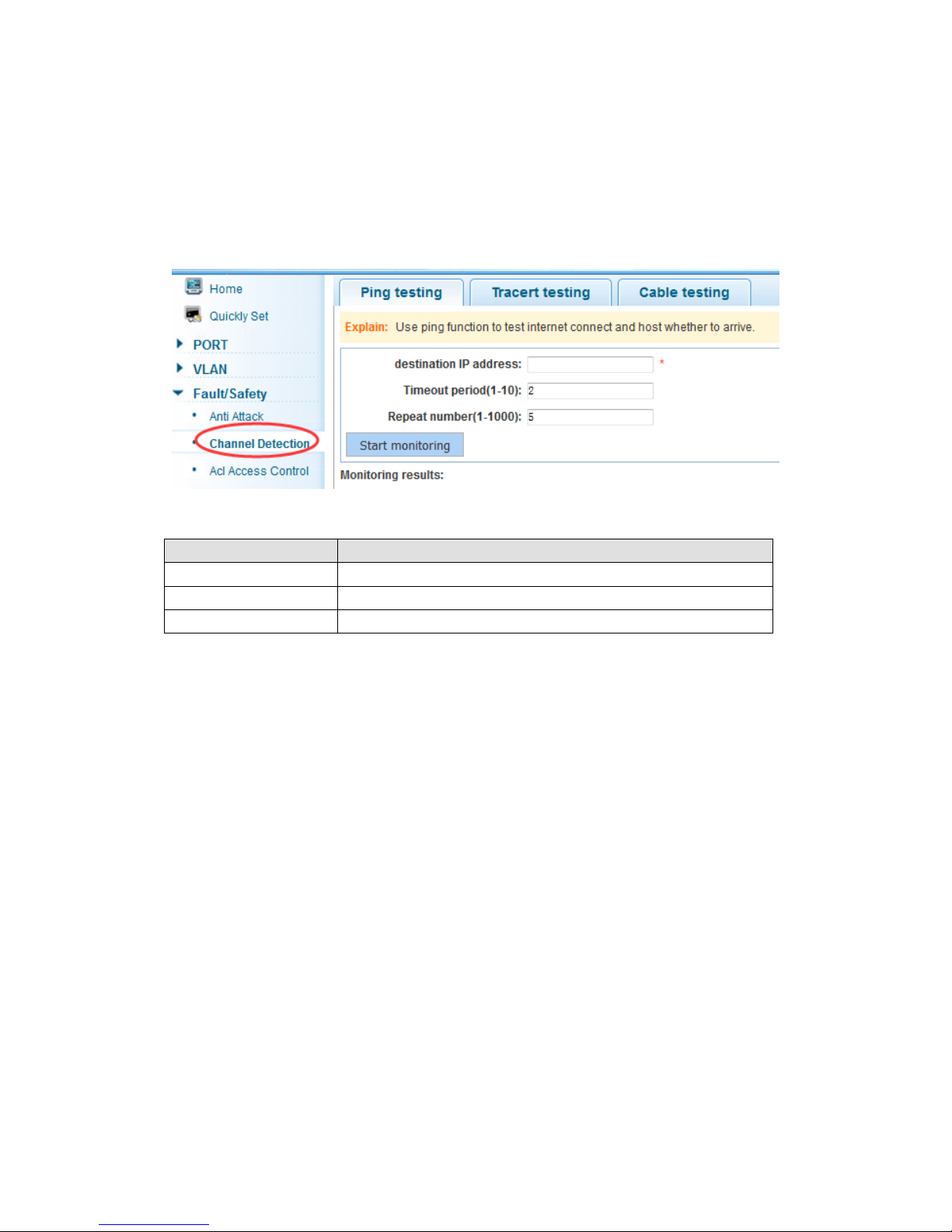
The binding option can be checked and deleted also.
4.4.2 Channel detection
4.4.2.1 Ping testing
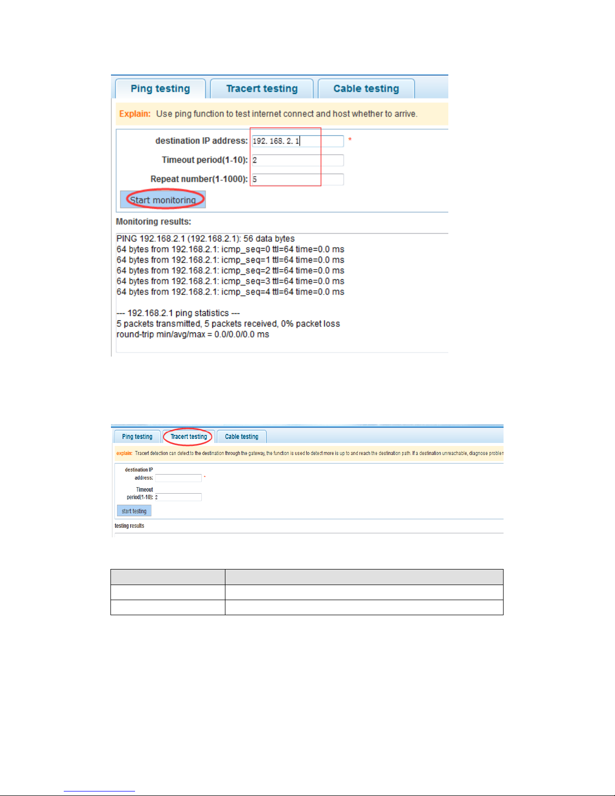
In the navigation bar select “Fault/Safety> Channel Detection>Ping testing”, use ping
function to test internet connection and host whether to arrive. As the following picture:
【Parameter Description】
Parameter
Description
destination IP address
Fill in the IP address of the need to detect
Timeout period
Range of 1 to 10
Repeat number
Testing number
【Instructions】
Use ping function to test internet connect and whether host can be arrived.
【Configuration Example】
Such as: PING the IP address of the connecting PC
Page 32
32
4.4.2.2 Tracert testing
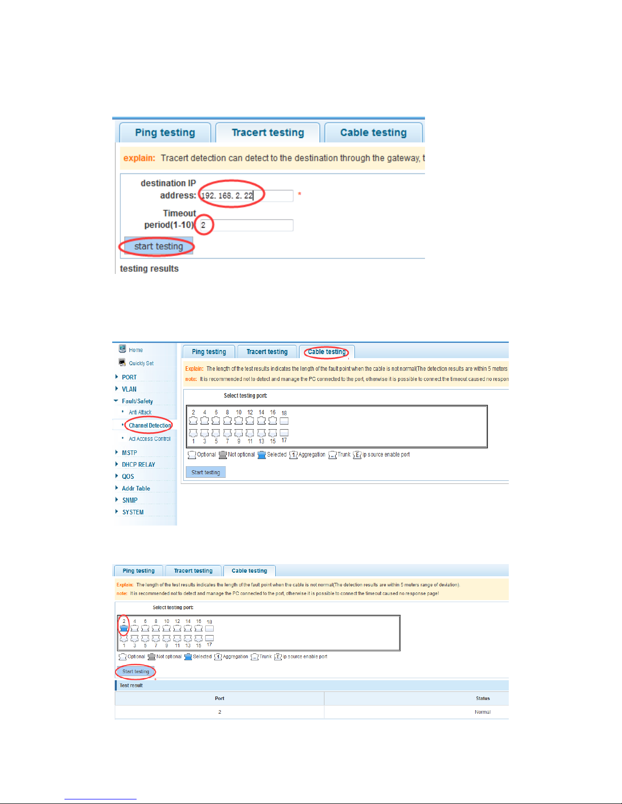
In the navigation bar select “Fault/Safety> Channel Detection>Tracert testing”, tracert
detection can detect to the destination through the gateway, as the following picture:
【Parameter Description】
Parameter
Description
destination IP address
Fill in the IP address of the need to detect
Timeout period
Range of 1 to 10
【Instruction】
The function is used to detect more is up to and reach the destination path. If a destination
unreachable, diagnose problems.
Page 33
33
【Configuration Example】
Such as: Tracert the IP address of the connecting PC
4.4.2.3 Cable testing
In the navigation bar select “Fault/Safety> Channel Detection>Cable testing”, can
detect connection device status, as the following picture:
【Configuration Example】
Page 34
34
4.4.3 ACL
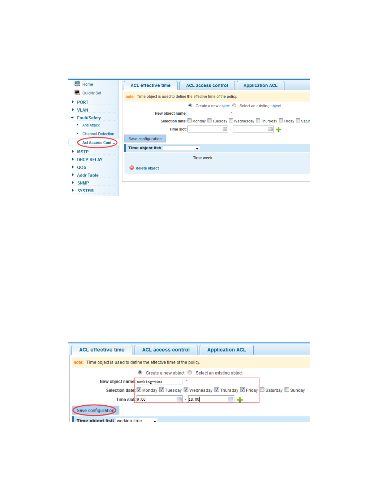
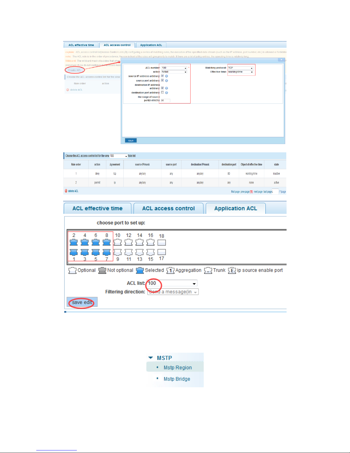
In the navigation bar select “Fault/Safety>Acl Access Control”, can be applied to port
ACL rules and Settings to take effect in time
【Instruction】
The ACL rules are sequenced, row in front of the match will be priority rule. The more
strategy items need more operating time.
Basic principles:
1. According to the order, as long as there is a meet, will not continue to find
2. Implied refused, if don't match, so must match the final implied refused entry
3. Any only under the condition of the minimum permissions to the user can satisfy their
demand
4. Don't forget to apply the ACL to the port
【Configuration Example】
Such as: test time is every Monday to Friday 9 to 18 points, set port 1-8 cannot access the
network
Steps: building ACL time - building ACL rules - is applied to the port
Page 35
35
4.5 MSTP
In the navigation bar select “MSTP”, you can set to the Mstp Region and Mstp Bridge
configuration.
Page 36
36
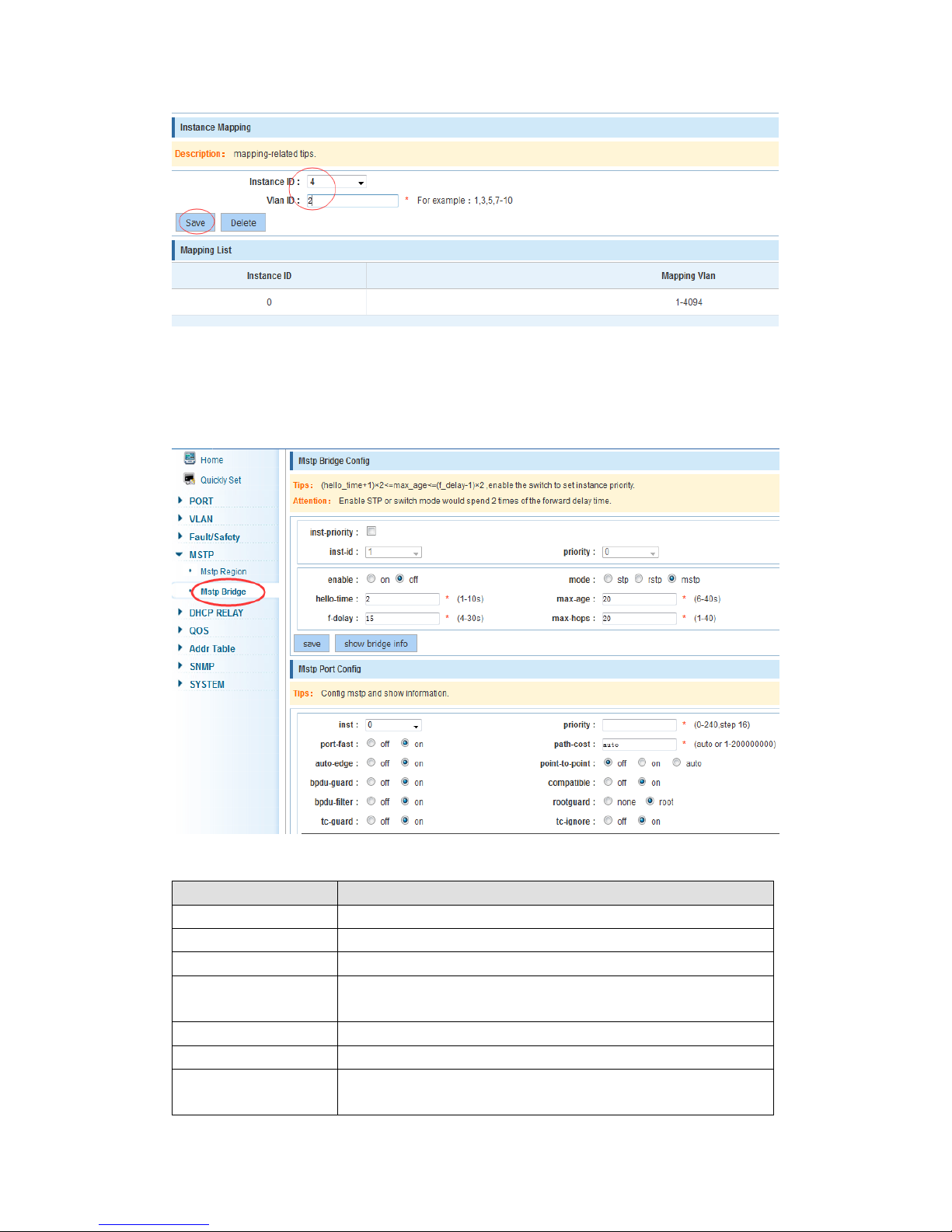
4.5.1 MSTP region
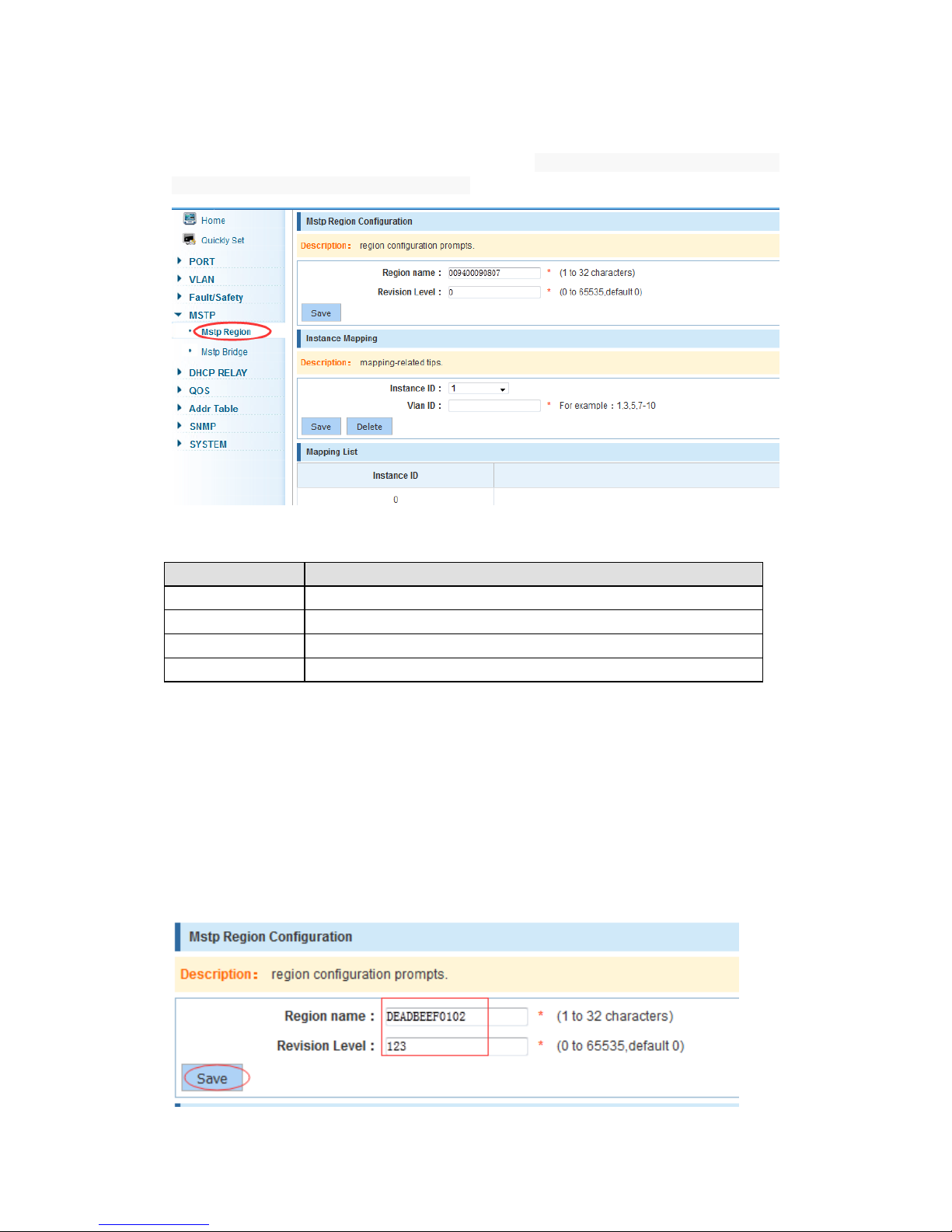
In the navigation bar select “MSTP>Mstp Region”, can modify the domain and domain
name, add instance mapped to a VLAN. As the following picture
【Parameter Description】
Parameter
Description
Region name
Configure the region name
Revision level
Parameter configuration revision level
Instance ID
Select configuration instance ID
VLAN ID
Mapping of the VLAN configuration instance
【Instruction】
An instance can only be mapped to a VLAN, instance and VLAN is a one-to-one
relationship.
【Configuration Example】
Such as: change the region to DEADBEEF0102, region name is 123, instance 4 is
mapped to a VLAN 2, in the first need to create a VLAN 2
Page 37
37
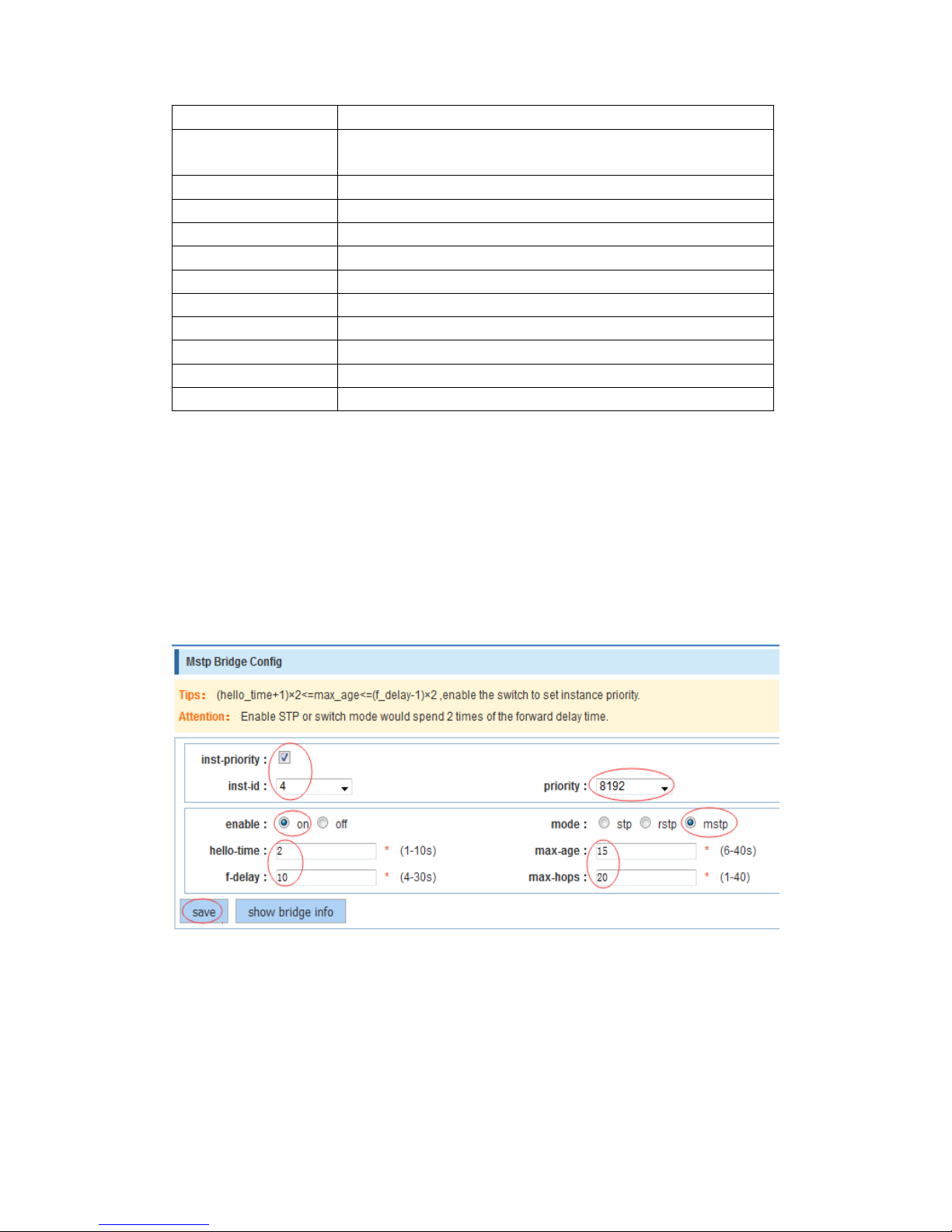
4.5.2 MSTP bridge
In the navigation bar select “MSTP>Mstp Bridge”, can be related to bridge, port
configuration, as the following picture:
【Parameter Description】
Parameter
Description
inst-priority
Whether open instance priority setting
Instance ID
Select the created instance id is configured
enable
Whether to open the STP bridge function
Bridge priority
Priority setting bridge example, the default instance bridge
priority for 32768
mode
The model is divided into: the STP, RSTP, MSTP
Hello-time
Switches sends bpdu in packet interval
Max-age
Ports are not yet received a message in the time, will initiate
topology changes
Page 38
38
Forward-delay
The state of the port switch time
Port-priority
Set port instance priority, defaults to 128, you must enter
multiple of 16, the range of 0-240
Path-cost
Configure port costs
Port-fast
Enable or disable Port-fast function
Auto-ege
Enable or disable Auto-ege function
Point-to-point
Enable or disable Point-to-point function
Bpdu guard
Enable or disable Bpdu guard function
Bpdu filter
Enable or disable Bpdu filter function
compatible
Enable or disable compatible function
Root guard
Enable or disable Root guard function
TC guard
Enable or disable TC guard function
TC filter
Enable or disable TC filter function
【Instruction】
(1) (hello_time+1)×2<=max age<=(f_delay-1)×2 ,enable the switch to set instance priority.
(2) Enable STP would spend 2 times of the forward delay time for Web connection.
【Configuration Example】
Such as:1)Open the STP, configuration has to create an instance of the priority,
configuration time parameters, set the pattern to MSTP
Page 39
39
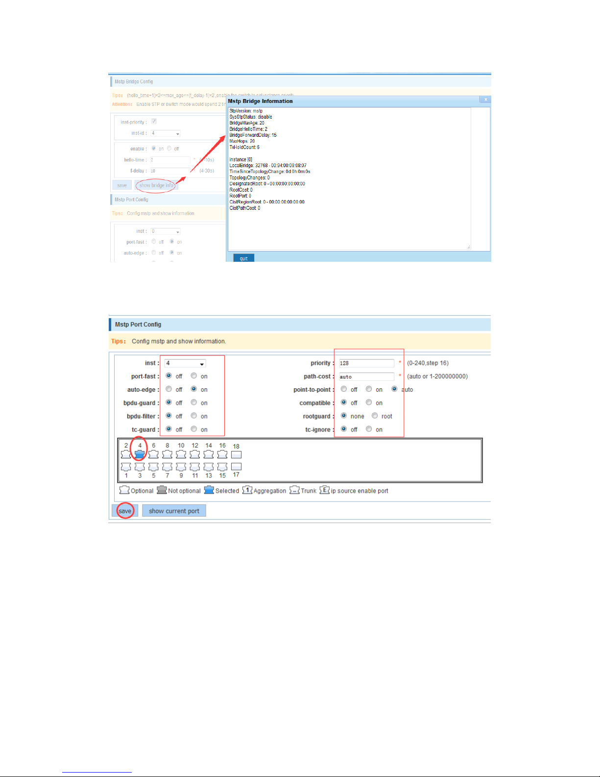
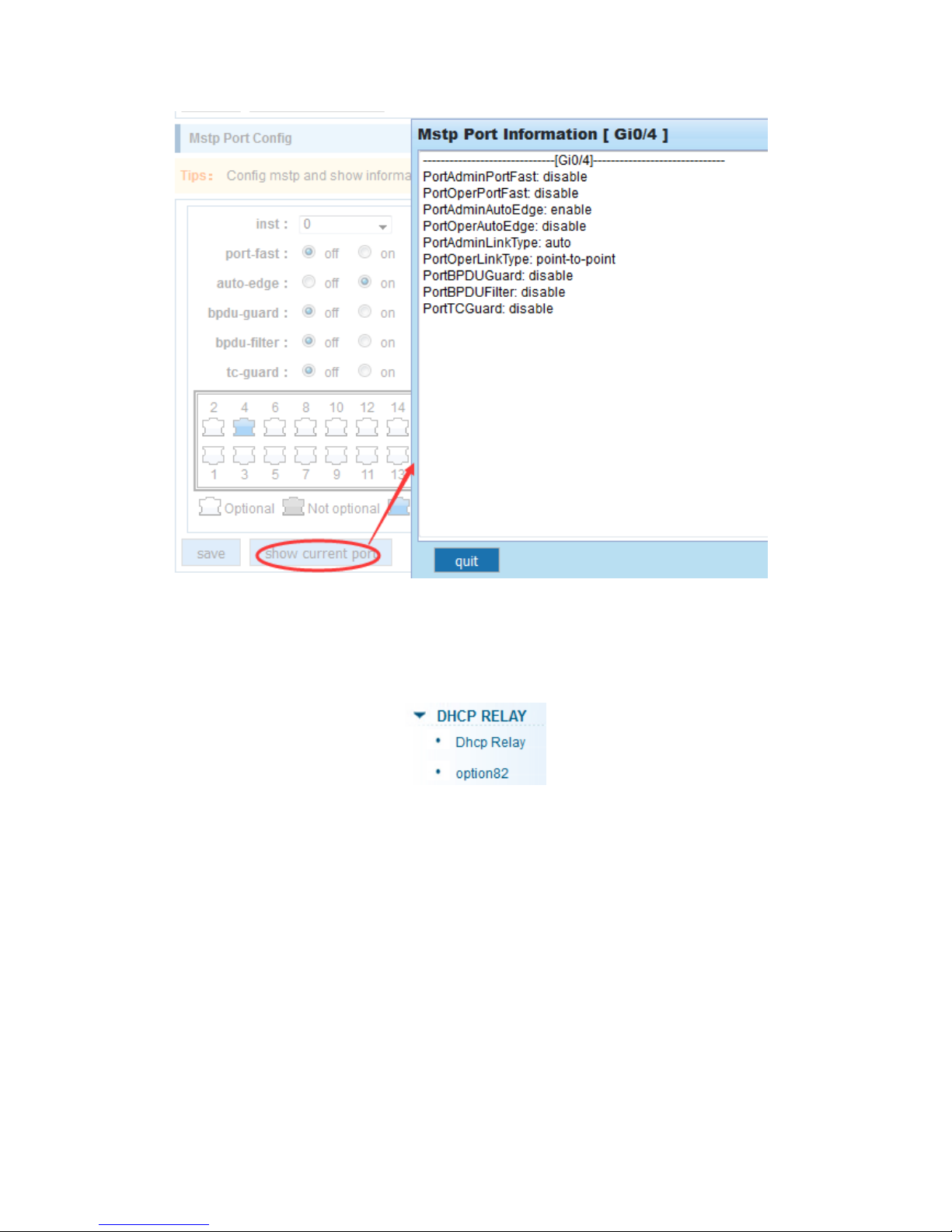
2)Set MSTP has launched port configuration, select the created instance, set priority
(port configuration is not online, on-line configuration will only take effect, can click on the
"view the current configuration" button to view the configured completed)
Page 40
40
4.6 DHCP relay
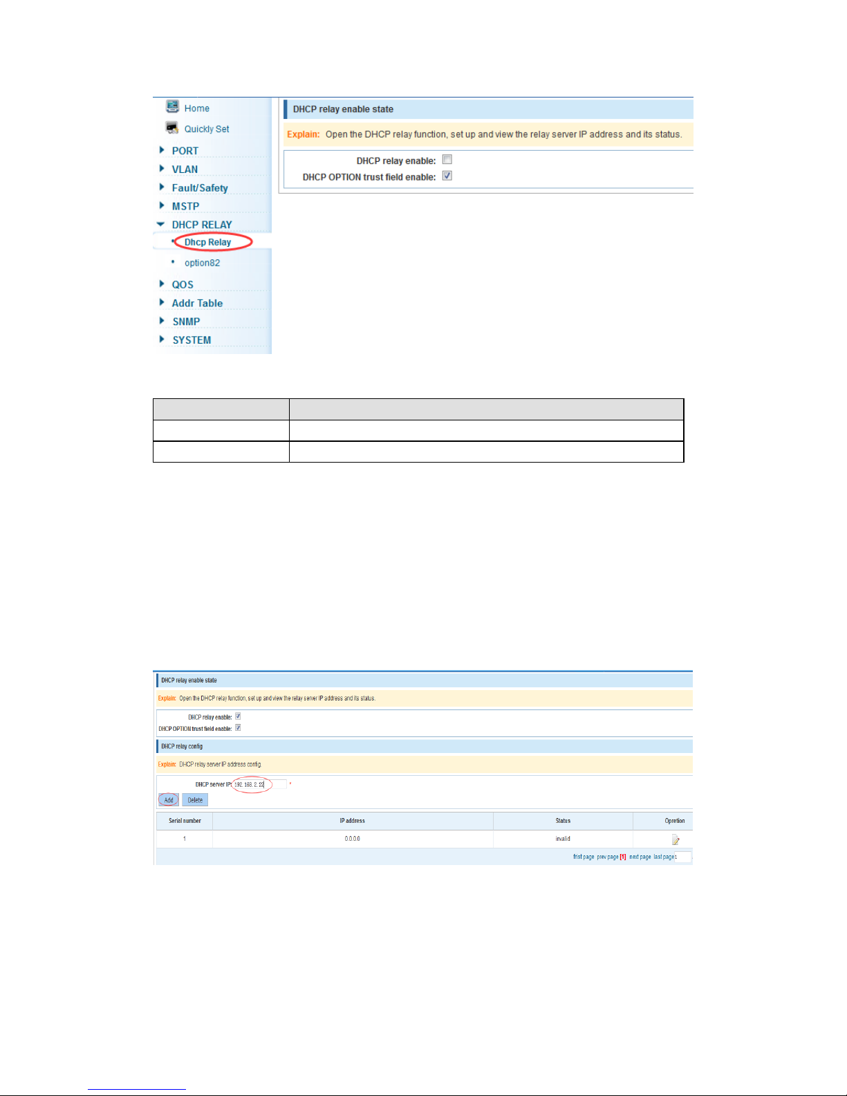
In the navigation bar select “DHCP RELAY”, you can set to the Dhcp Relay and
option82.
4.6.1 DHCP relay
In the navigation bar select “Dhcp Relay”, open the DHCP relay function, set up and view
the relay server IP address and its status. As the following picture
Page 41
41
【Parameter Description】
Parameter
Description
IP address
DHCP server address
status
Invalid and vaild
【Instruction】
If open the function of relay agent, then receives the broadcast DHCP message, to be
delivered in the form of unicast to configure on the server. The DHCP server to IP and
switches in the same network segment will only take effect.
【Configuration Example】
Such as: setting DHCP server IP for 192.168.2.22
4.6.2 Option82
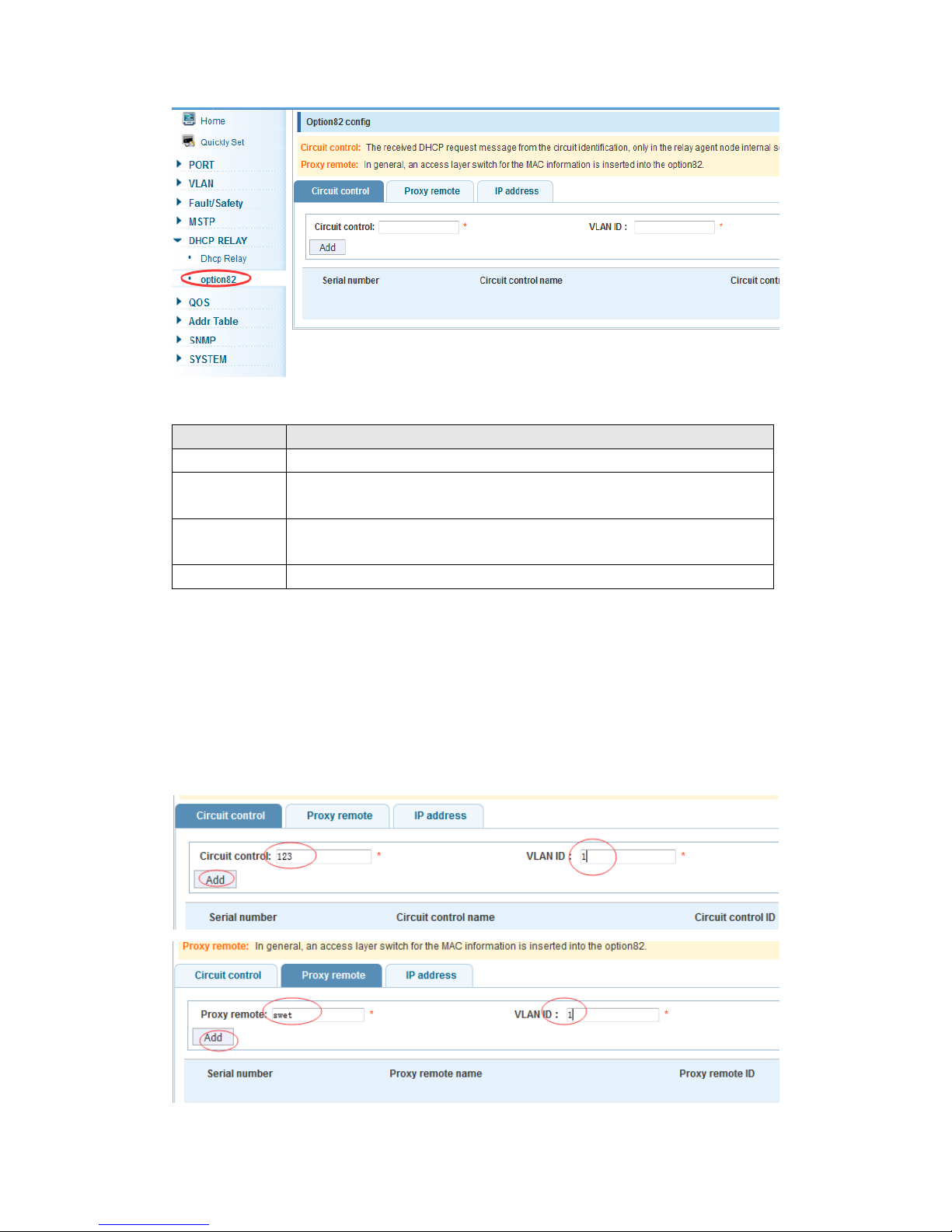
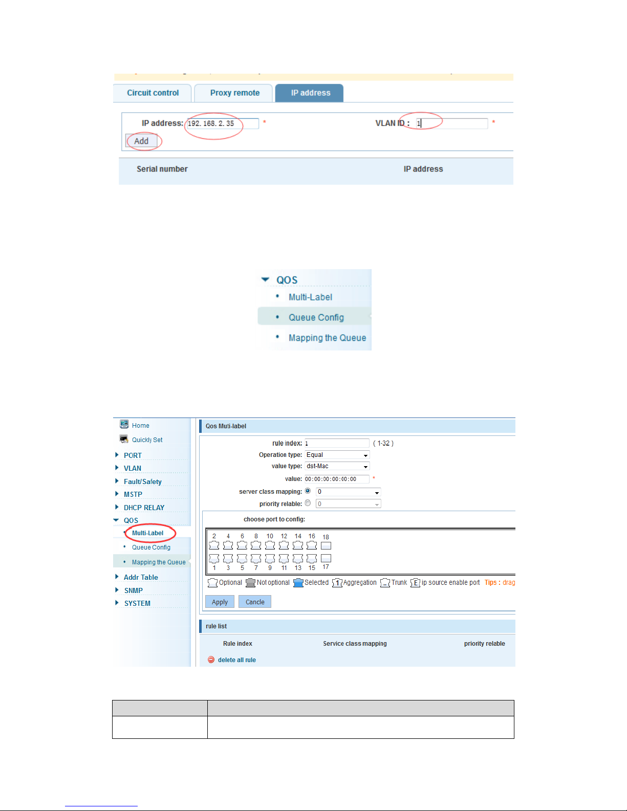
In the navigation bar select “DHCP RELAY>option82”, can set to OPTION82 circuit
control, proxy remote , IP address. As the following picture:
Page 42
42
【Parameter Description】
Parameter
Description
VLAN id
the DHCP request message in the VLAN, value range is 1 ~ 4094
Circuit control
Circuit ID to populate the user custom content, scope of string length
is 3 ~ 63
Proxy remote
Configuration ASCII remote id string value, the length of the range of
1 ~ 63
IP address
Decimal IP address
【Instruction】
Switches relay information to the DHCP server will take option82, VLAN ID must be
configured to DHCP message taken VLAN can bring option82 information.
【Configuration Example】
Such as: add circuit control, proxy remote, IP address information
Page 43
43
4.7 QoS
In the navigation bar select “QoS”, you can set to the QoS Multi-Label, Queue Config
and Mapping the Queue.
4.7.1 QoS multi-label
In the navigation bar select “QoS>QoS Multi-Label”, according to different rules tag or
queue map packets for port traffic data. As the following picture
【Parameter Description】
Parameter
Description
Rule index
By setting the rule of heavy tag index number, the current switch
Page 44
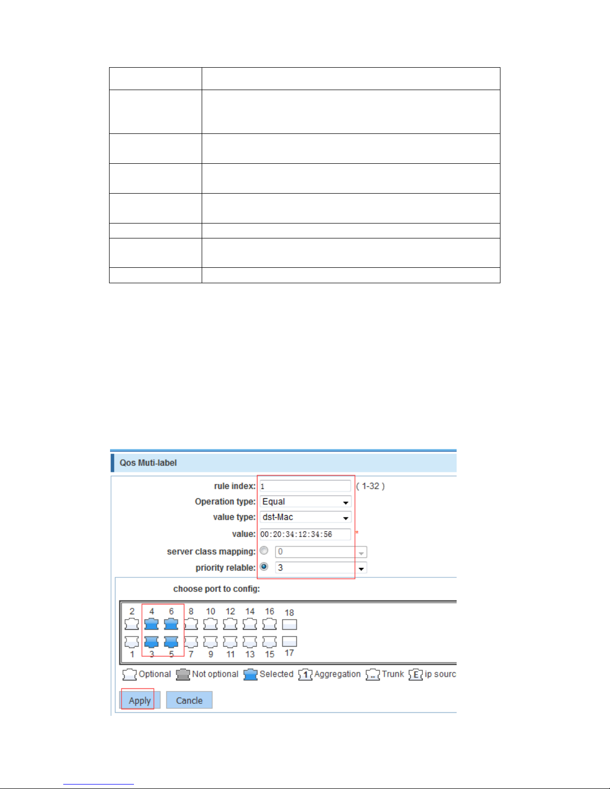
44
can be set up 32 rule
Operation type
Choose always said - match the match, all the data for tags
Choose can be set to equal matching rules, comply with the rules
of heavy tag data
Server class
mapping
Adaptable to the rules of the heavy tag which data is mapped to a
queue
Priority re-label
Conform to the rules of heavy tag data to the marked priority
values
Value type
Set heavy tag matching rules, such as choice goal Mac, just check
the data destination Mac address is in accordance with the rules
value
Set the matching value
Choose port to
config
The application of heavy tag on which interface
apply
Click on the application of heavy marking rules to take effect
【Instruction】
According to the different matching rules to map different packages to different cos, and
then according to the mapping relationship cos and queue to map different packets to
different queue, also can set the priority value of a tag multi-label packets.
【Configuration Example】
Such as: transfer packets with MAC 00:02:03:0b:89:12 as the destination address
forwarded to the port 3, 4, 5, 6, with remarked priority 3
Page 45
45
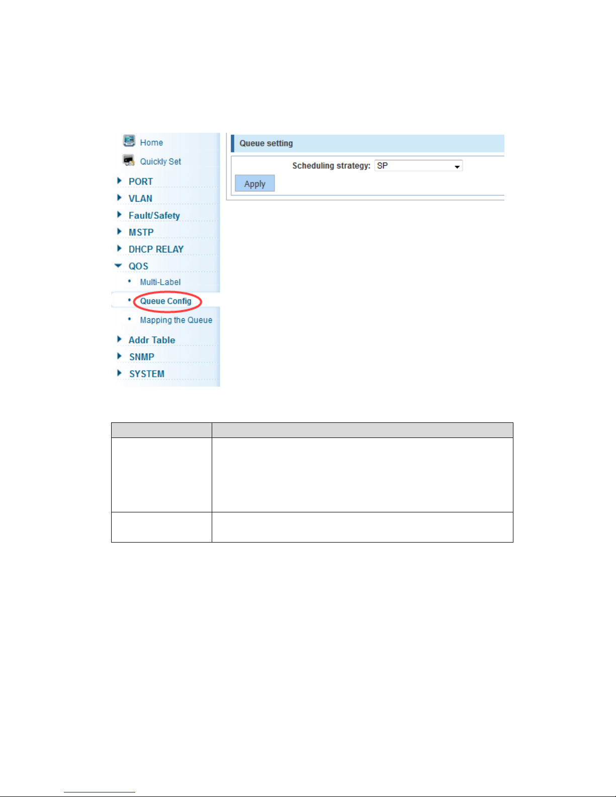
4.7.2 Queue config
In the navigation bar select “QoS>Queue Config”, can set up queue scheduling policy.
As the following picture:
【Parameter Description】
Parameter
Description
Scheduling strategy
Can choose four kinds of modes:
RR round-robin scheduling
SP absolute priority scheduling
WRR weighted round-robin scheduling
WFQ weighted fair scheduling
WRR-weights
Set the weights of each queue, they will be in proportion to occupy
the bandwidth to send data
【Instruction】
Queue 7 cannot be 0.
【Configuration Example】
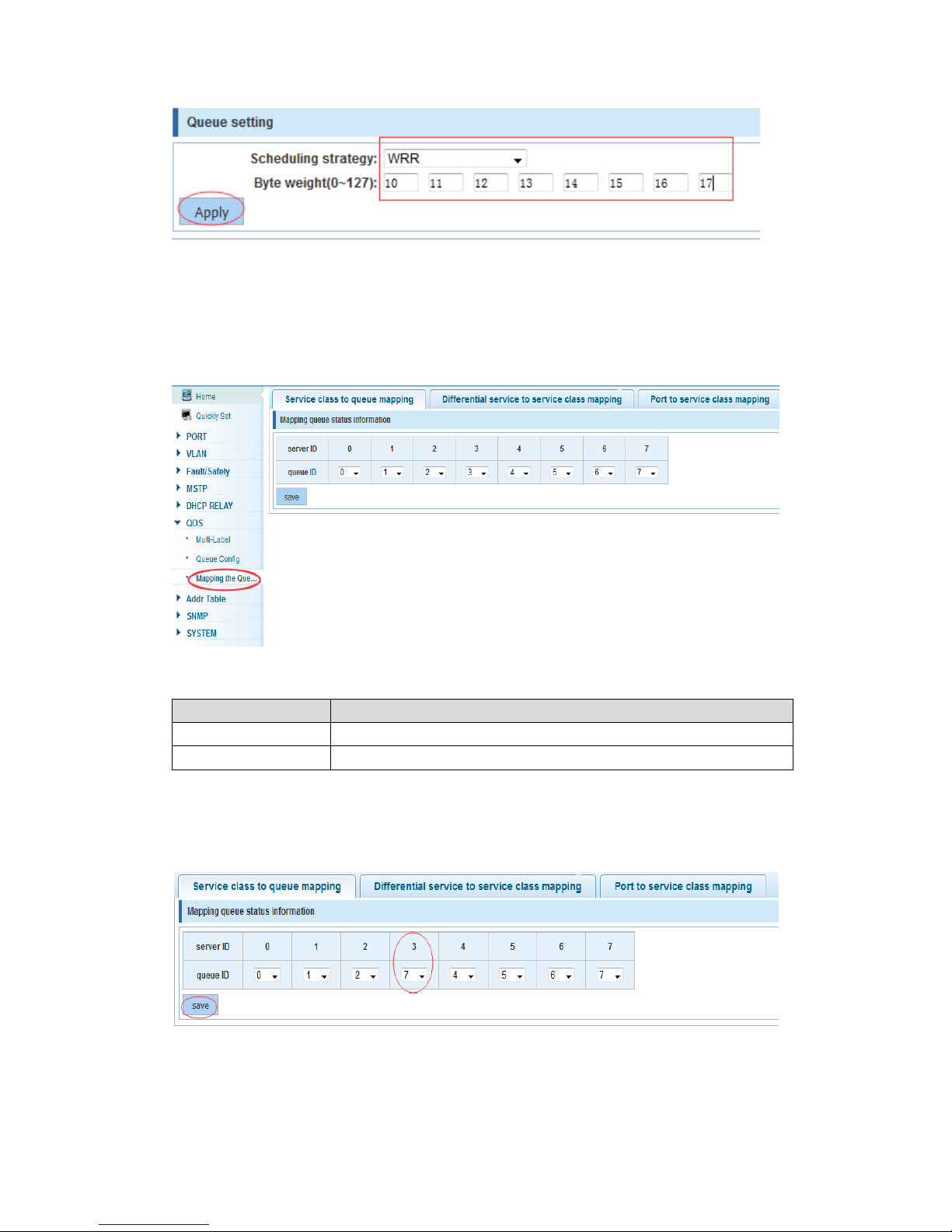
Such as: set the scheduling strategy for WRR, weight value respectively, 10, 11, 12, 13,
14, 15, 16, 17.
Page 46
46
4.7.3 Mapping the queue
4.7.3.1 Service class queue mapping
In the navigation bar select “QoS>Mapping the Queue”, service category can be
mapped to the corresponding queue. As the following picture
【Parameter Description】
Parameter
Description
Server ID
COS the VLAN priority fields (0 to 7)
Queue ID
Set each cosine value mapping queue number (0 to 7)
【Configuration Example】
Such as: mapping cos 3 to the queue 7, set the queue weight 7 to 10
Page 47
47
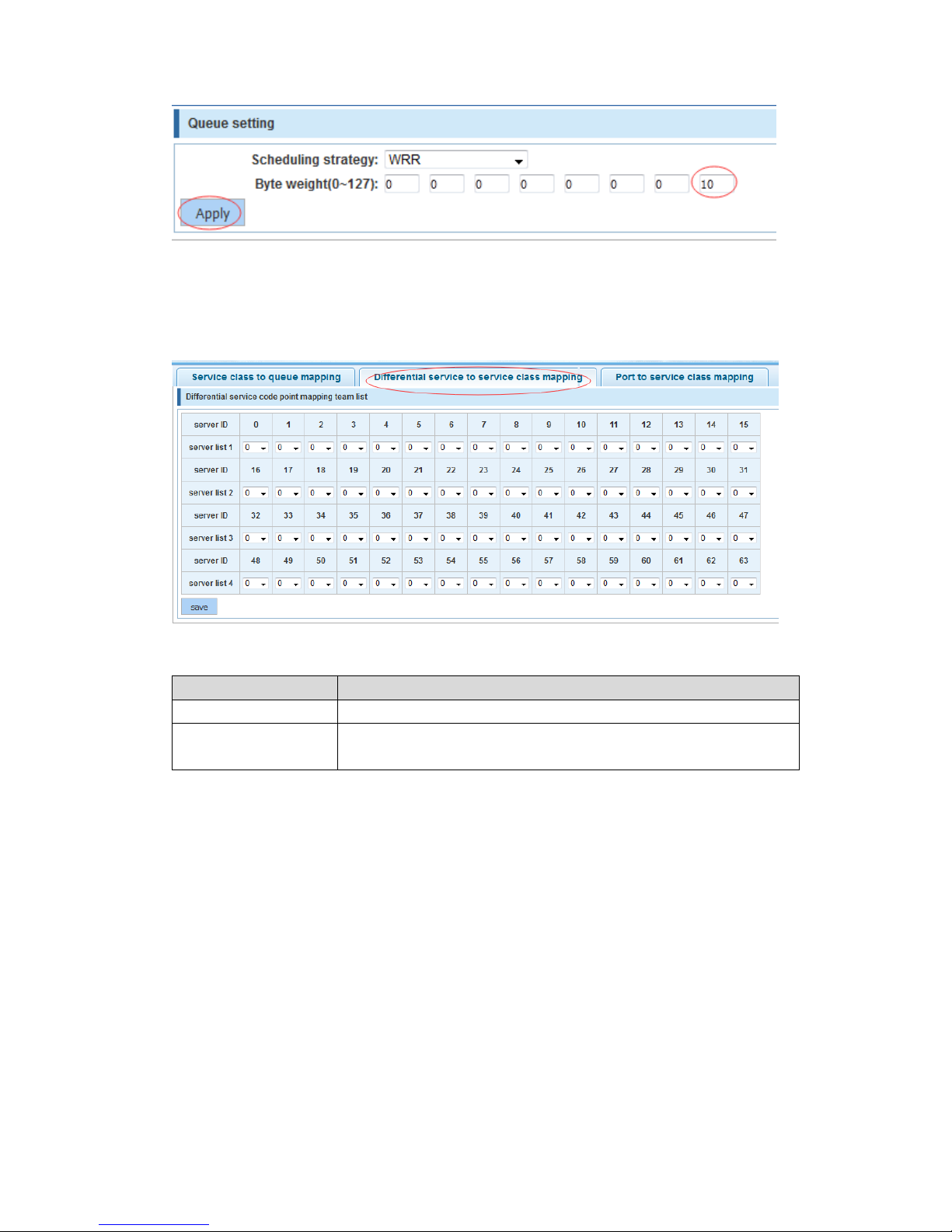
4.7.3.2 Differential service class mapping
In the navigation bar select “QoS>Mapping the Queue>Differential service to service
class mapping”, differential service can be mapped to the corresponding service
categories. As the following picture:
【Parameter Description】
Parameter
Description
Server list
DSCP field has seven (0-63) is divided into four tables
Queue ID
Map the DSCP to COS fields (0 to 7), based on the cosine is
mapped to a queue
【Instruction】
Cos priority is greater than the DSCP, DSCP priority is greater than the port
【Configuration Example】
Such as: mapping cos 5 to servers whose DSCP value is 3, 12 or 23
Page 48
48
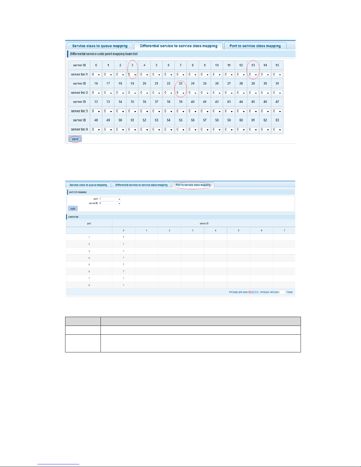
4.7.3.3 Port to service class mapping
In the navigation bar elect “QoS>Mapping the Queue>Port to service class mapping”,
port can be mapped to the corresponding service categories. As the following picture:
【Parameter Description】
Parameter
Description
Port
Select the port number (0-18)
Service ID
Mapped to the service ID, and then according to the service ID into the
queue
【Instruction】
Cos priority is greater than the DSCP, DSCP priority is greater than the port
【Configuration Example】
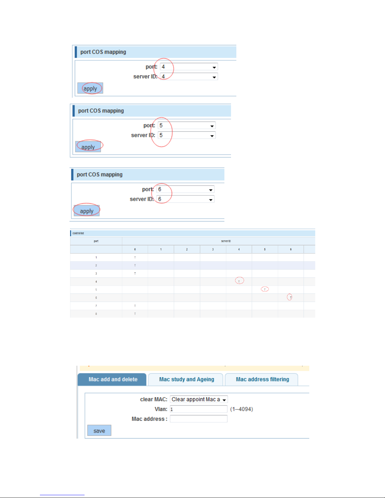
Such as: port 4, 5, 6 respectively cos4, cos5, cos6.
Page 49
49
4.8 Address table
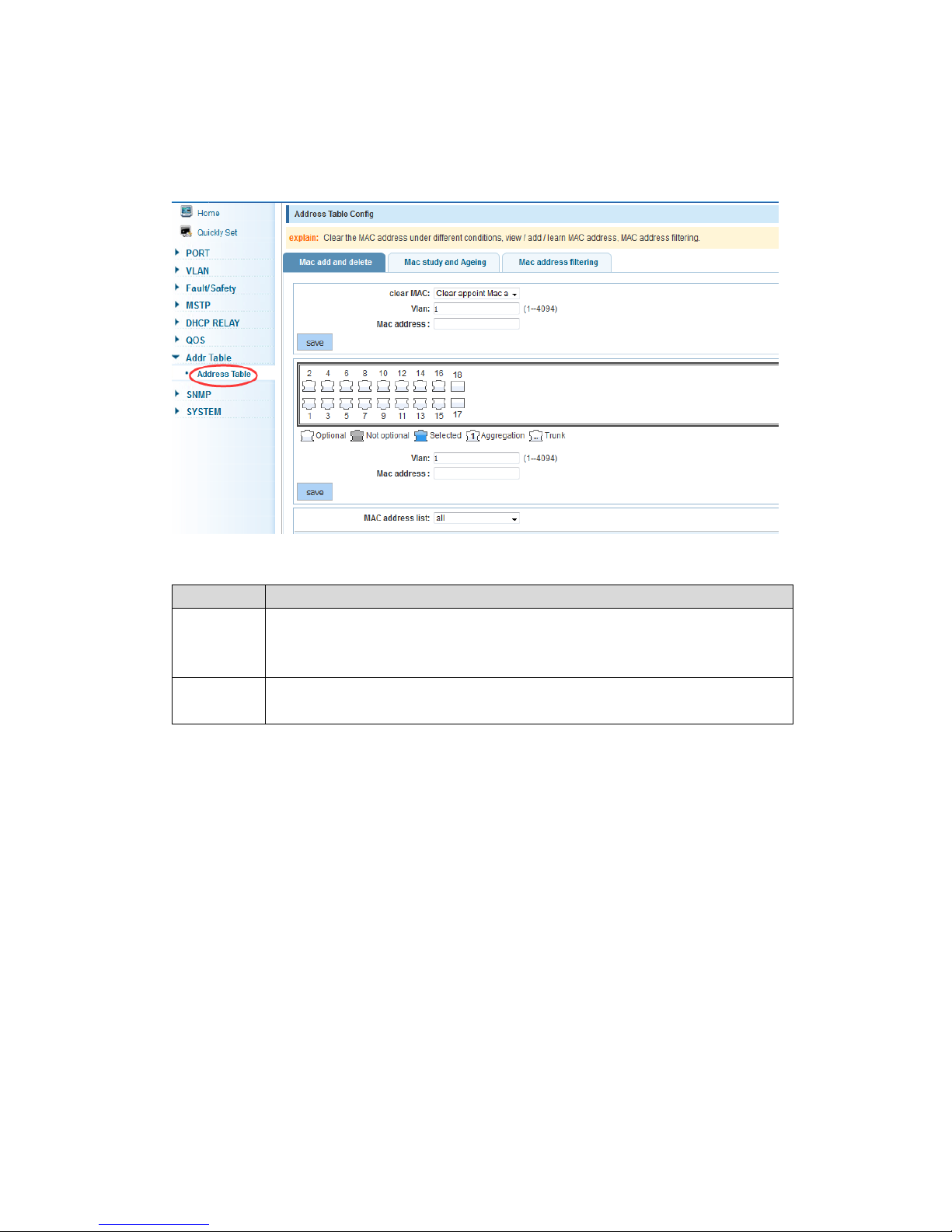
In the navigation bar select “Addr Table”, you can set to MAC add and delete, MAC
study and aging and MAC address filtering.
Page 50
50
4.8.1 Mac add and delete
In the navigation bar select “Addr Table>Mac add and delete”, you can add static Mac
and delete Mac and view to the current of the Mac address table. As the following picture:
【Parameter Description】
Parameter
Description
Clear Mac
Can choose to clear the multicast Mac address, clear dynamic unicast Mac
address, clear static unicast Mac address, clear the specified Mac address,
Mac address table
VLAN
Fill in the need to add or delete VLAN id, not create VLANs to create can
only take effect
【Instruction】
According to different conditions to view/add/learn the Mac address
【Configuration Example】
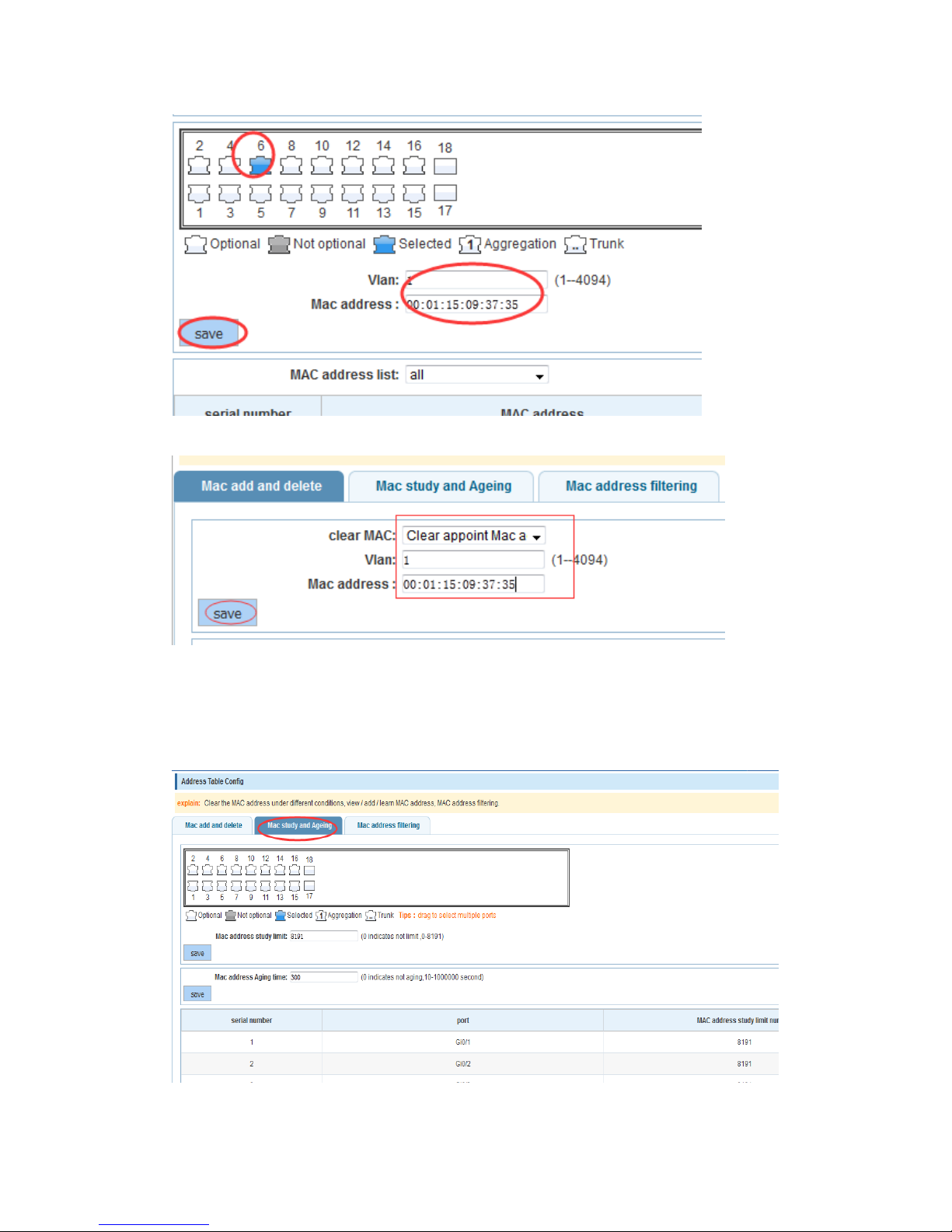
Such as: 1) The port 6 Mac set to static Mac
Page 51
51
2)Clear port 6 static Mac addresses
4.8.2 Mac study and aging
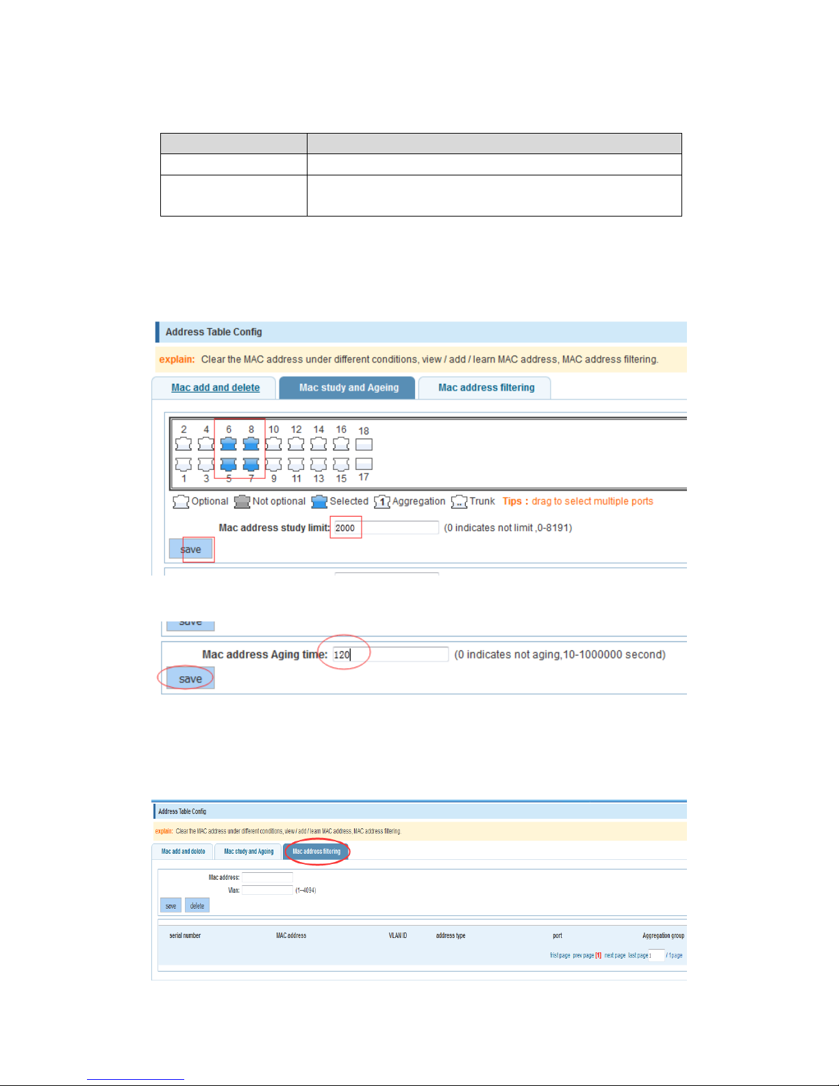
In the navigation bar select “Addr Table>Mac study and Aging”, can set up port Mac
address study limit and Mac address aging time. As the following picture:
Page 52
52
【Parameter Description】
Parameter
Description
Mac address
Range 0-8191,default 8191
Mac address study
limit
Default 300
【Configuration Example】
Such as: 1) Setting study limit to 2000 for port 5, 6, 7, 8 address
2) Disconnect the port or keep static for 2 minutes, the learned Mac address of the port
will disappear automatically from the Mac address table
4.8.3 Mac address filtering
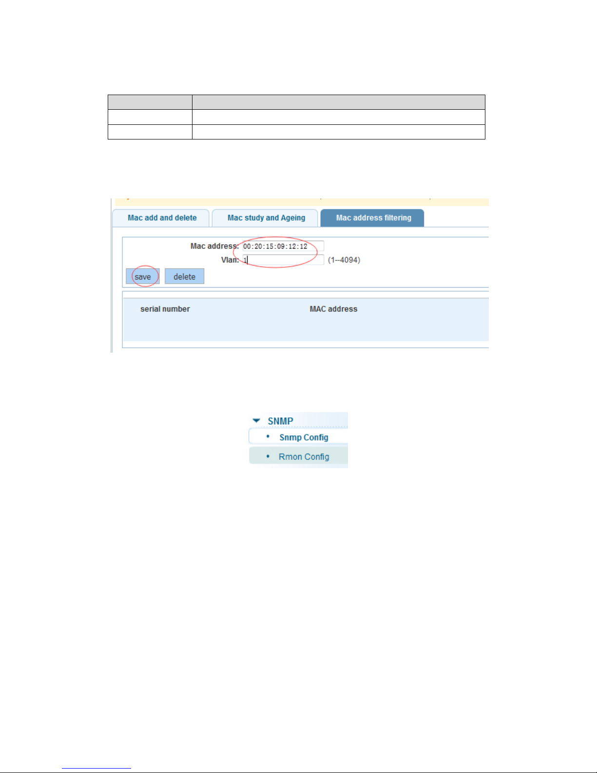
In the navigation bar select “Addr Table>Mac address filtering”, the needless MAC
address can be filtered according to the condition. As the following picture:
Page 53
53
【Parameter Description】
Parameter
Description
Mac address
Can’t add multicast Mac address
VLAN
VLAN ID
【Configuration Example】
Such as: Add the Mac address 00:20:15:09:12:12 to the filter table
4.9 Snmp config
In the navigation bar select “SNMP”, you can set to the Snmp Config and Rmon Config.
4.9.1 Snmp config
4.9.1.1 Snmp config
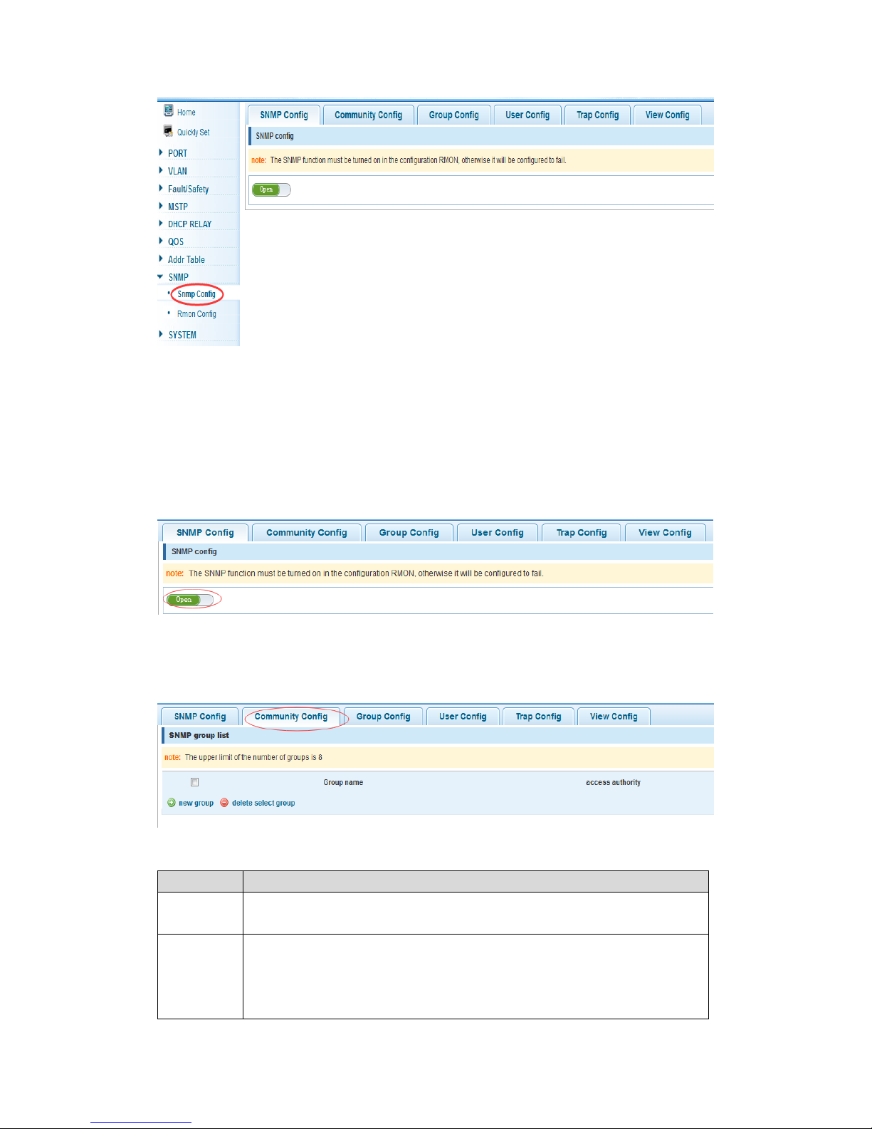
In the navigation bar select “SNMP >Snmp config”, you can enable Snmp function. As
the following picture:
Page 54
54
【Instruction】
The SNMP function must be turned ON when configure RMON, otherwise it will be failed
to be configured.
【Configuration Example】
Such as: open Snmp
4.9.1.2 Community config
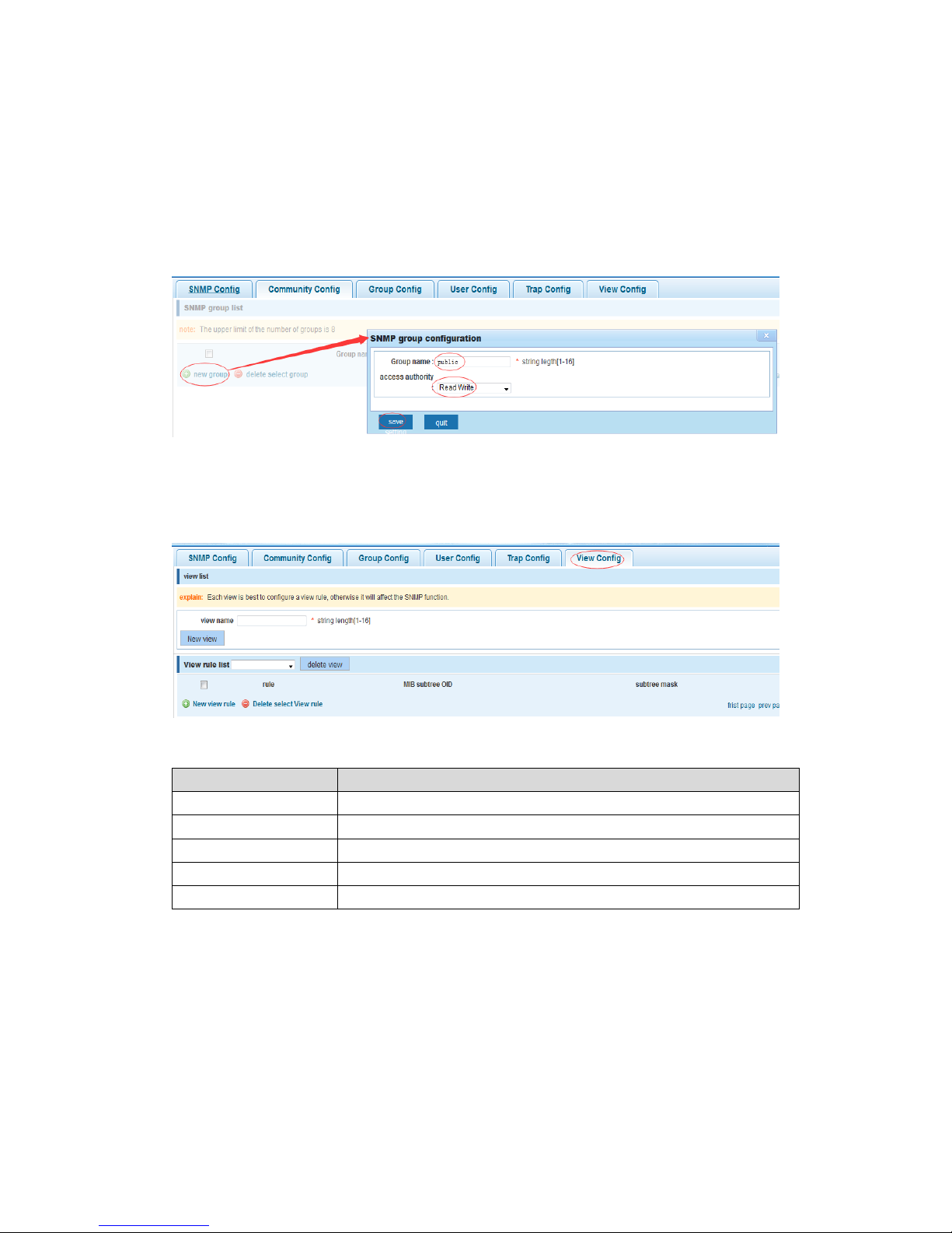
In the navigation bar select “SNMP >Snmp Config>Community Config”, can specify
the access authority for groups. As the following picture
【Parameter Description】
Parameter
Description
group
Community strings, seem as the password using for communication
between the NMS and Snmp agent.
Access
authority
Read-only: specify the NMS (Snmp host) of MIB variables can only be
read, cannot be modified
Read and write: specify the NMS (Snmp host) of MIB variables can be
read and modified.
Page 55
55
【Instruction】
The upper limit of the number of Trap configuration is 8.
【Configuration Example】
Such as: add a read-write group called public
4.9.1.3 View config
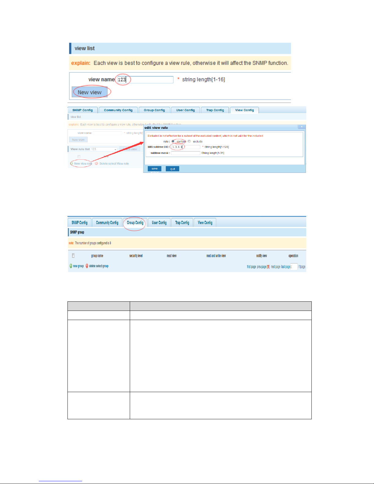
In the navigation bar select “SNMP >Snmp Config>View Config”, set View rules list to
allow or reject access to some of the MIB objects. As the following picture
【Parameter Description】
Parameter
Description
View name
View mane
include
Indicate the MIB object number contained within the view
exclude
Indicate the MIB object son number was left out of view
MIB subtree OID
View the associated MIB object, is a number of MIB
Subtree mask
MIB OID mask
【Instruction】
It’s the best to configure a view rule for each view, otherwise it will affect the SNMP
function
【Configuration Example】
Such as: establish a view 123 which include MIB subtree OID .1.3.6.1
Page 56
56
4.9.1.4 Group config
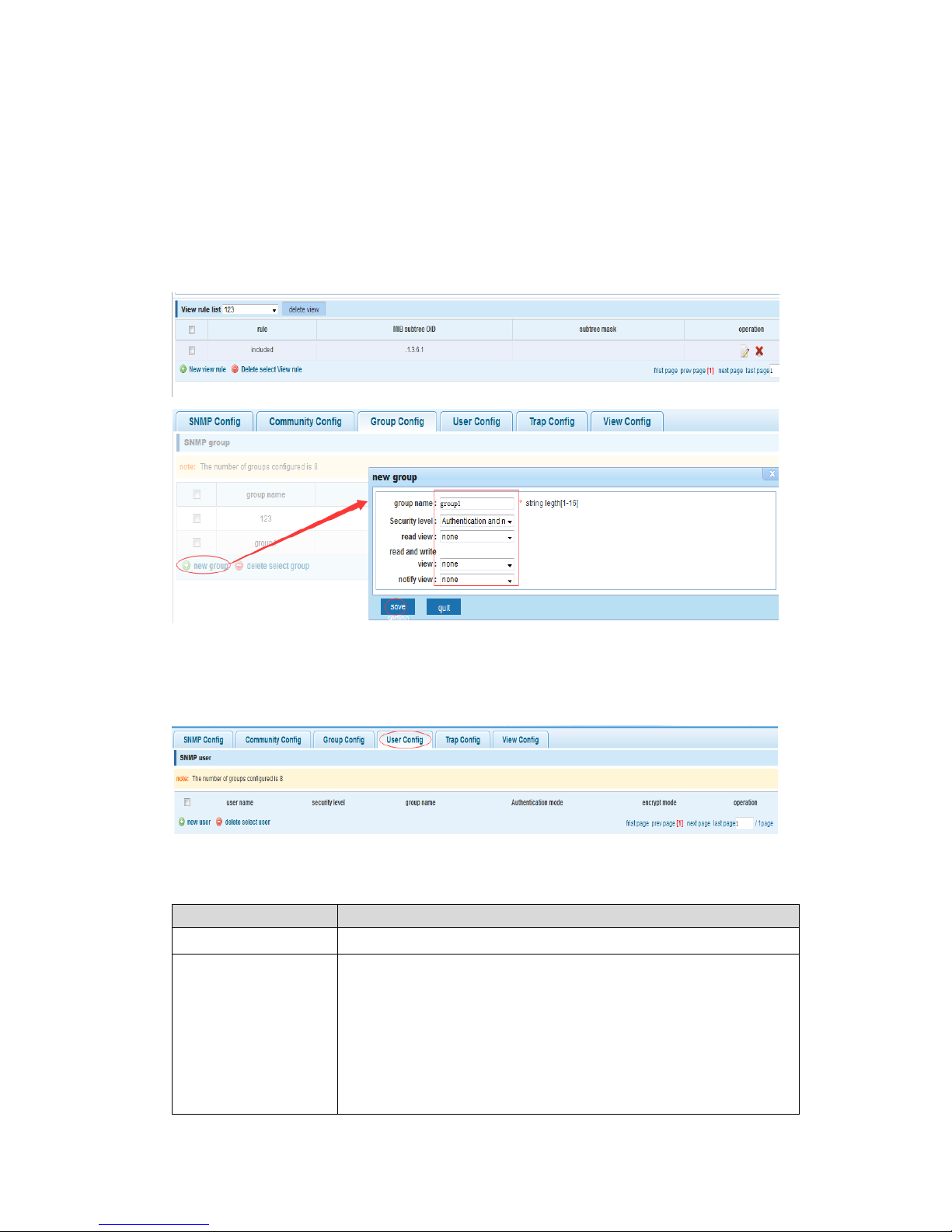
In the navigation bar select “SNMP>Snmp Config>Group Config”, setting Snmp group.
As the following picture:
【Parameter Description】
Parameter
Description
Group name
Group name
Security level
Need authentication without encryption: message from users in
this group need to verify but the data aren’t encrypted
Neither need authentication nor encryption: message from users
in this group don’t need to verify and the data aren’t encrypted
also
Both need authentication and encryption: message from users in
this group need to be verified and data in the message should be
encrypted.
Read view, read and
write view ,study
view
The associated view name
Page 57
57
【Instruction】
The upper limit of the number of Trap configuration is 8, and you must create views first
before create the groups.
【Configuration Example】
Such as: firstly create new view 123, then create new group of group1
4.9.1.5 User config
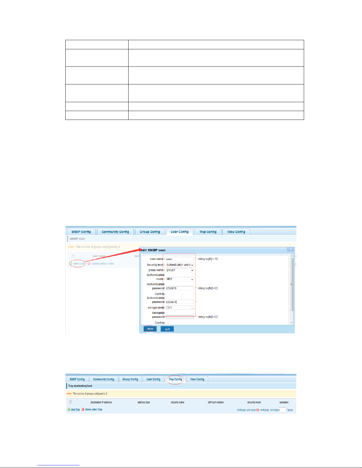
In the navigation bar select “SNMP>Snmp Config>User Config”, setting Snmp user. As
the following picture:
【Parameter Description】
Parameter
Description
User name
User name, range 1-16
Security level
Need authentication without encryption: message from users in
this group need to verify but the data aren’t encrypted
Neither need authentication nor encryption: message from users
in this group don’t need to verify and the data aren’t encrypted
also
Both need authentication and encryption: message from users in
this group need to be verified and data in the message should be
Page 58
58
encrypted.
Authentication mode
Specified use MD5 authentication protocol or SHA authentication
protocol
Authentication
password
Range 8-10
encrypt mode
Specified using AES encryption protocol or DES encryption
protocol
Group name
A user group name
encrypt password
Range 8-60
【Instruction】
The upper limit of the number of Trap configuration is 8 and you must create views and
groups first, the user's security level must be consistent with its mother group. Add
authentication and encryption mode for a user and configure belong groups for this user,
then the user will be used Snmpv3 protocol to connect.
【Configuration Example】
Such as: create new view 123, and create new group group1, then create new users
user1
4.9.1.6 Trap
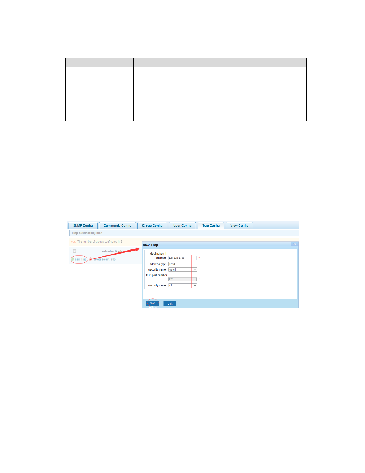
In the navigation bar select “SNMP>Snmp Config>Trap Config”, can specify the host
(NMS) sending the trap messages to Snmp. As the following picture:
Page 59
59
【Parameter Description】
Parameter
Description
Destination IP address
Snmp host ipv4 address
Security name
Snmp user name
version
V1,V2,V3
Security mode
Specified using AES encryption protocol or DES encryption
protocol
Group name
User group name
【Instruction】
The Trap cap on the number configuration of 8, you can configure a number of different
Snmp Trap host used to receive trap messages. Trigger the trap message time: port
Linkup/LinkDown, equipment of cold - start (restart when power supply drop)/warm - start
(a warm restart), and Rmon set port statistical fluctuation threshold.
【Configuration Example】
Such as: setting host 192.168.2.30 to receive trap information
4.9.2 Rmon config
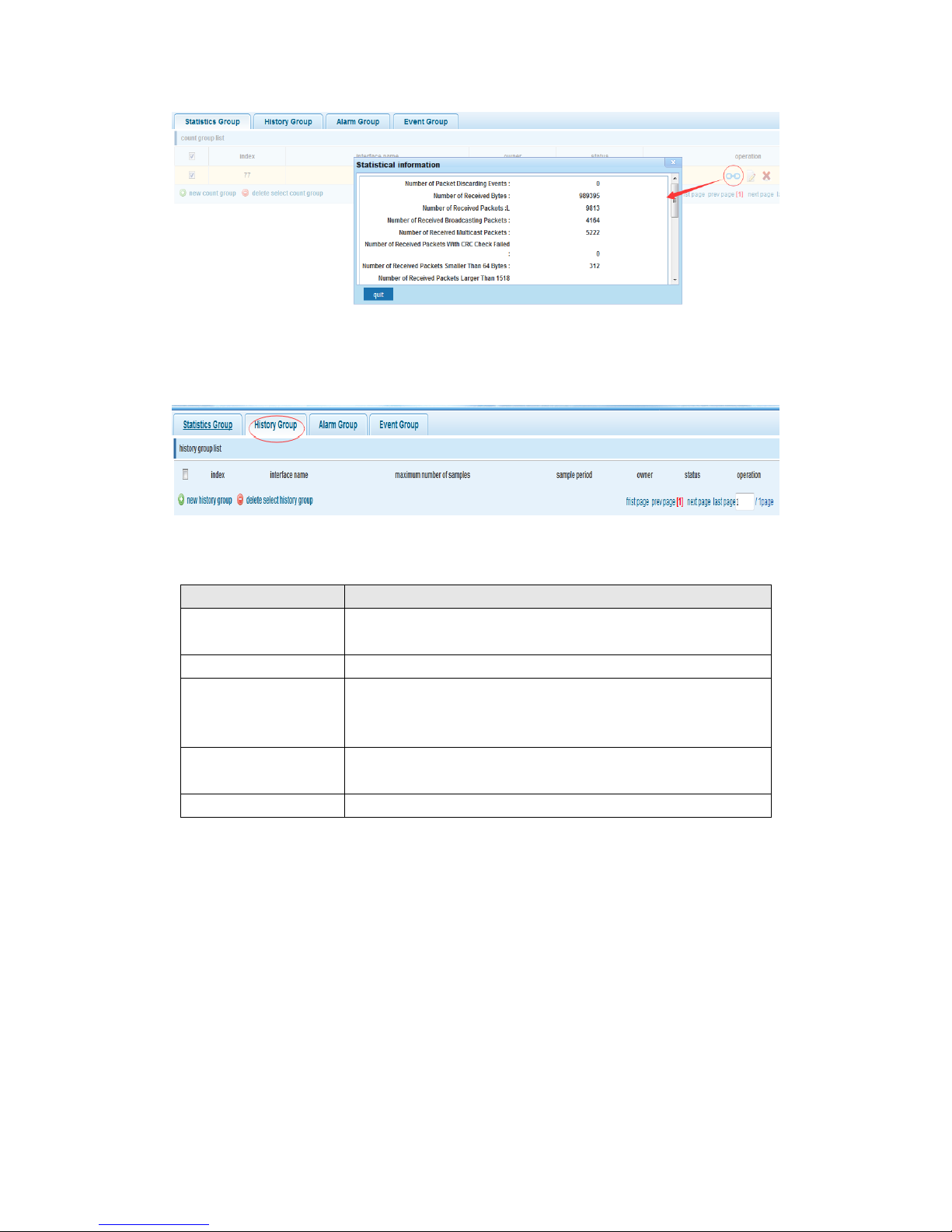
4.9.2.1 Statistics group
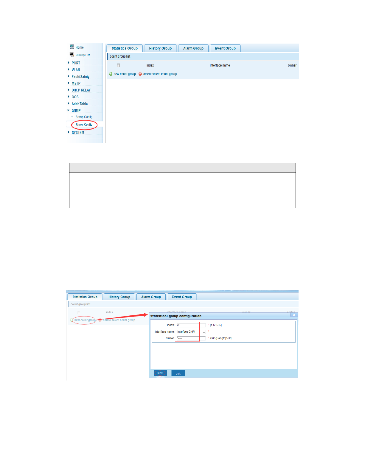
In the navigation bar select “SNMP>Rmon Config>Statistics Group”, set an Ethernet
interface statistics .As the following picture:
Page 60
60
【Parameter Description】
Parameter
Description
index
The index number, the value range of statistical information
table is 1 ~ 65535
Interface mane
To monitor the source port
owner
Set the table creator, range: 1 ~ 30 characters of a string
【Instruction】
At the time of configuration Rmon Snmp functions must be opened first, otherwise the
prompt dialog box will appear.
【Configuration Example】
Such as: set up monitoring Ethernet port 4 and check the data
Page 61
61
4.9.2.2 History group
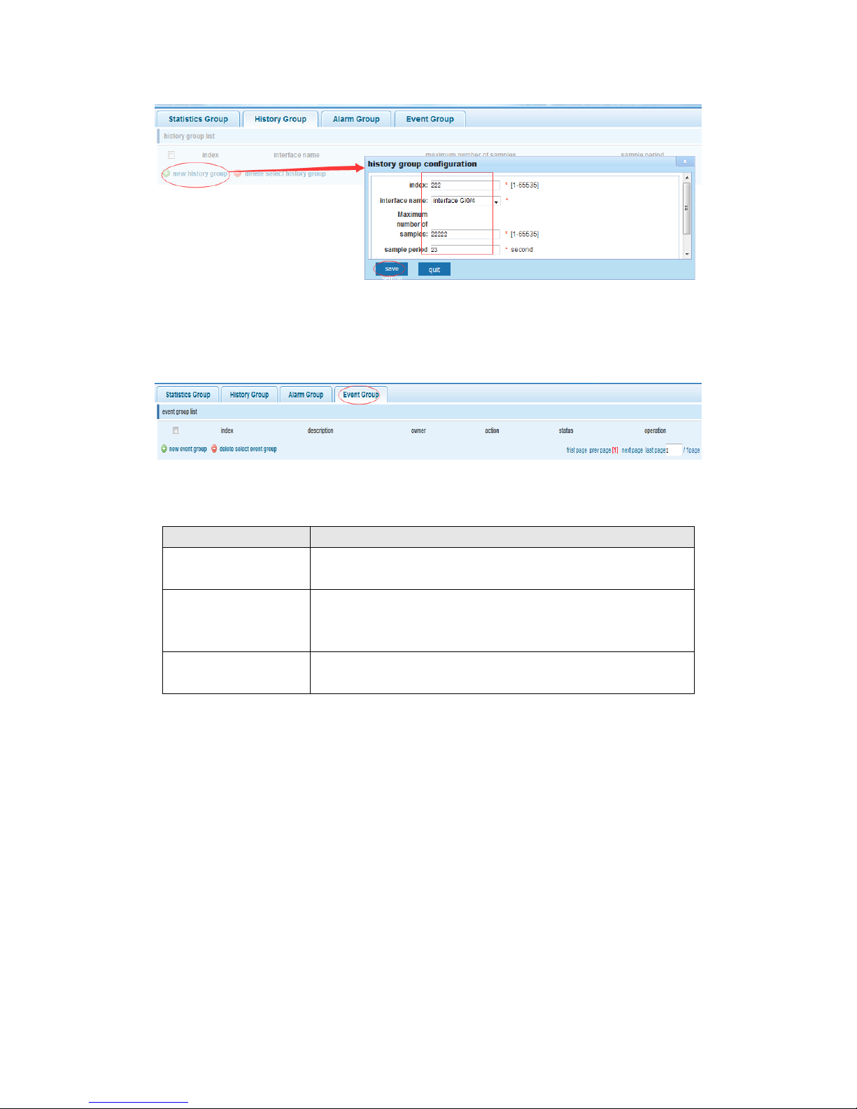
In the navigation bar select “SNMP>Rmon Config>History Group”, recording the
history of an Ethernet interface information. As the following picture
【Parameter Description】
Parameter
Description
index
Index number for items in historical control table, value
range is 1 ~ 65535
Interface name
To record the Ethernet interface
Maximum number of
samples
Set the capacity for the history table corresponding to control
table item, namely the Max for number of records the history
table, value range is 1 ~ 65535
Sample period
Set up the statistical period, scope for 5 ~ 3600, the unit is in
seconds
owner
Set the table creator, range: 1 ~ 30 characters of a string
【Instruction】
At the time of configuration Rmon Snmp functions must be opened first, otherwise the
prompt dialog box will appear.
【Configuration Example】
Such as: monitor Ethernet port 5 historical information
Page 62
62
4.9.2.3 Event group
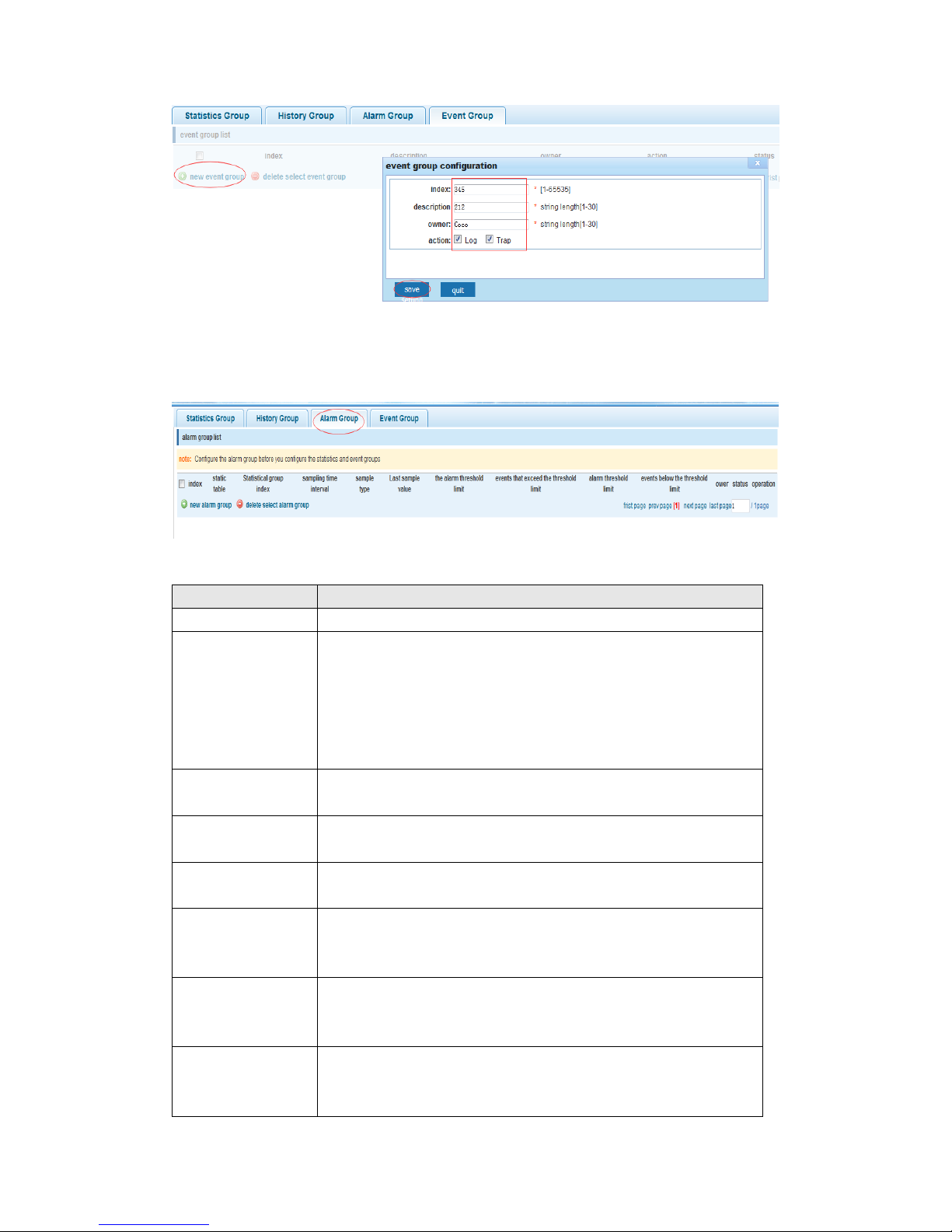
In the navigation bar select “SNMP >Rmon Config>Event Group”, define the way to
record events when triggered them. As the following picture
【Parameter Description】
Parameter
Description
index
The index number for event table, the value range of the
event table is 1 ~ 65535
description
The Trap events, when the event is triggered, the system will
send the Trap message
Log events, when the event is triggered, the system will log
owner
Set the table creator, ownername for 1 ~ 30 characters of a
string
【Instruction】
At the time of configuration Rmon Snmp functions must be opened first, otherwise the
prompt dialog box will appear.
【Configuration Example】
Such as: create an event to trigger 345, the system sends the trap message and log
Page 63
63
4.9.2.4 Alarm group
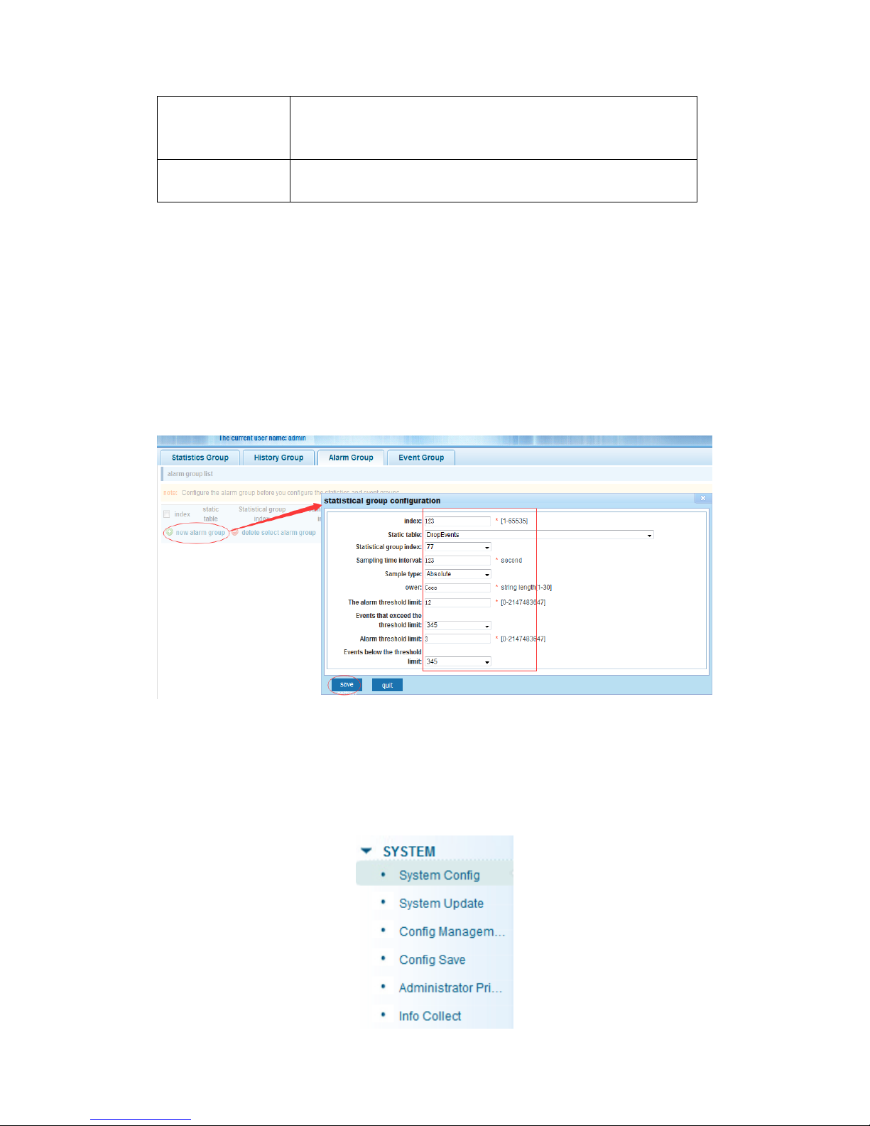
In the navigation bar select “SNMP>Rmon Config>Alarm Group”, define alarm group.
As the following picture
【Parameter Description】
Parameter
Description
index
The index number for alarm list items, value range is 1 ~ 65535
Static table
Statistical type values :3:DropEvents; 4:Octets; 5:Pkts;
6:BroadcastPkts; 7:MulticastPkts; 8:CRCAlignErrors;
9:UndersizePkts; 10:OversizePkts; 11:Fragments; 12:Jabbers;
12:Collisions; 14:Pkts64Octets; 15:Pkts65to127Octets;
16:Pkts128to255Octets; 17:Pkts256to511Octets;
18:Pkts512to1023Octets; 19:Pkts1024to1518Octets
statistical index
Set up the corresponding statistics statistical index number,
decided to statistics to monitor the port number
Sampling interval
Sampling time interval, the scope for 5 ~ 65535, the unit for
seconds
The sampling type
Sample types for the absolute value of sampling, the sampling
time arrived directly extracting the value of a variable
The latest
sampling
Sampling type for change value sampling, extraction of the
arrival of the sampling time is variable in the change of the
sampling interval value
The alarm
threshold upper
limit
Set the upper limit the parameter values
The alarm
threshold lower
limit
Set the lower limit parameter values
Page 64
64
Above/below the
threshold limit of
events
Upper/lower limit reached, for each event
owner
Set the table creator, owner name for 1 ~ 30 characters of a
string
【Instruction】
At the time of configuration Rmon Snmp functions must be opened first, otherwise the
prompt dialog box will appear. This configuration needs to configure statistics groups and
events first.
【Configuration Example】
Such as: new statistics group of 77 and the event group 345, start-up alarm when value is
more than 12 or below than lower limit 3
4.10 System
In the navigation bar select “SYSTEM”, you can set to the System Config, System
Update, Config Management, Config Save, Administrator Privileges and Info
Collect.
Page 65
65
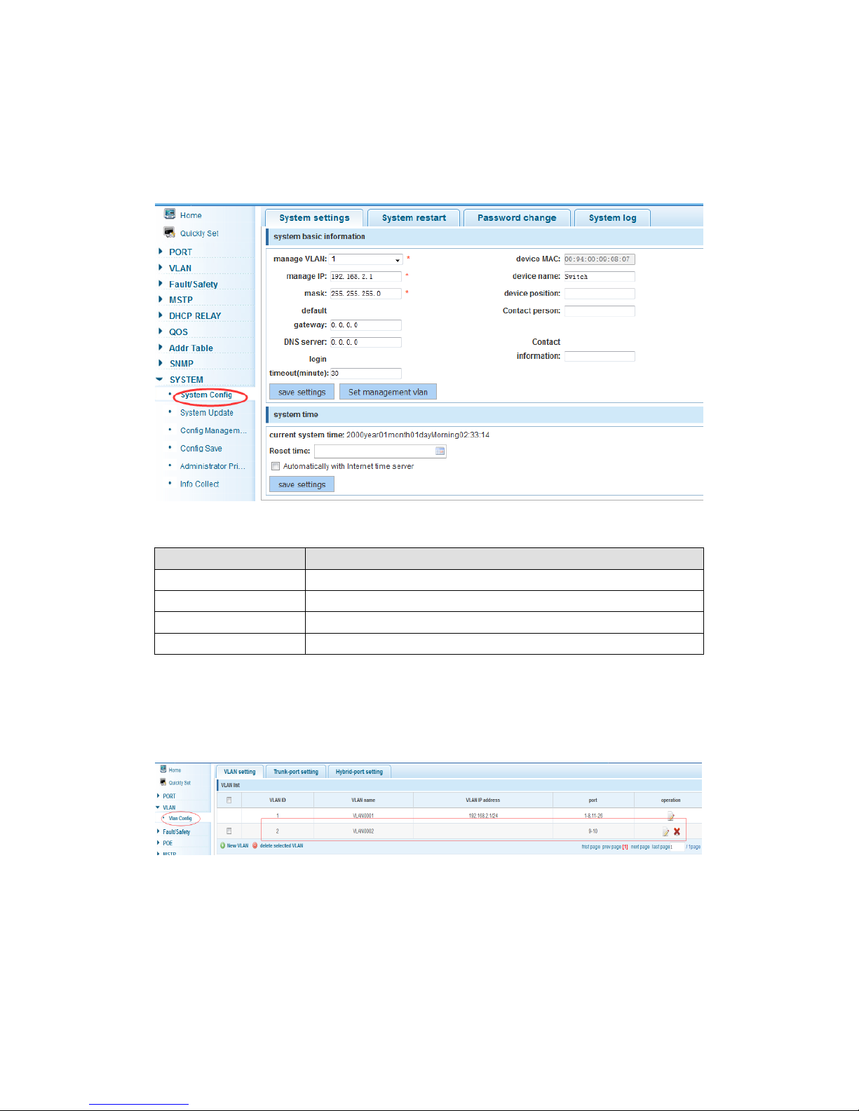
4.10.1 System
4.10.1.1 System config
In the navigation bar select “SYSTEM>System Config>System settings”, setting basic
information for the switch. As the following picture:
【Parameter Description】
Parameter
Description
Device name
switch name
Manage VLAN
Switches use VLAN management
Manage ip
Switch IP address management
timeout
Don't use more than login timeout after login to log in again
【Configuration Example】
Such as: 1) Set up the VLAN 2 is management VLAN, should first created VLAN 2 in the
VLAN Settings object, and set a free port in the VLAN 2
Page 66
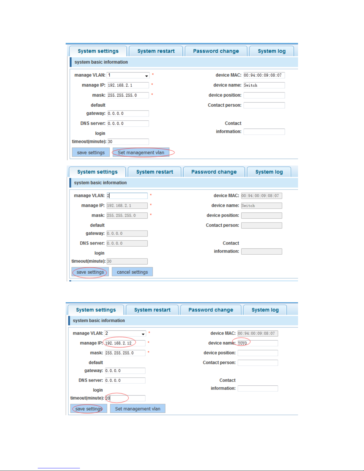
66
2) Insert the PC interface 9 or 10 ports, set up the management IP for 192.168.2.12,
device name is yoyo, timeout for 20 minutes
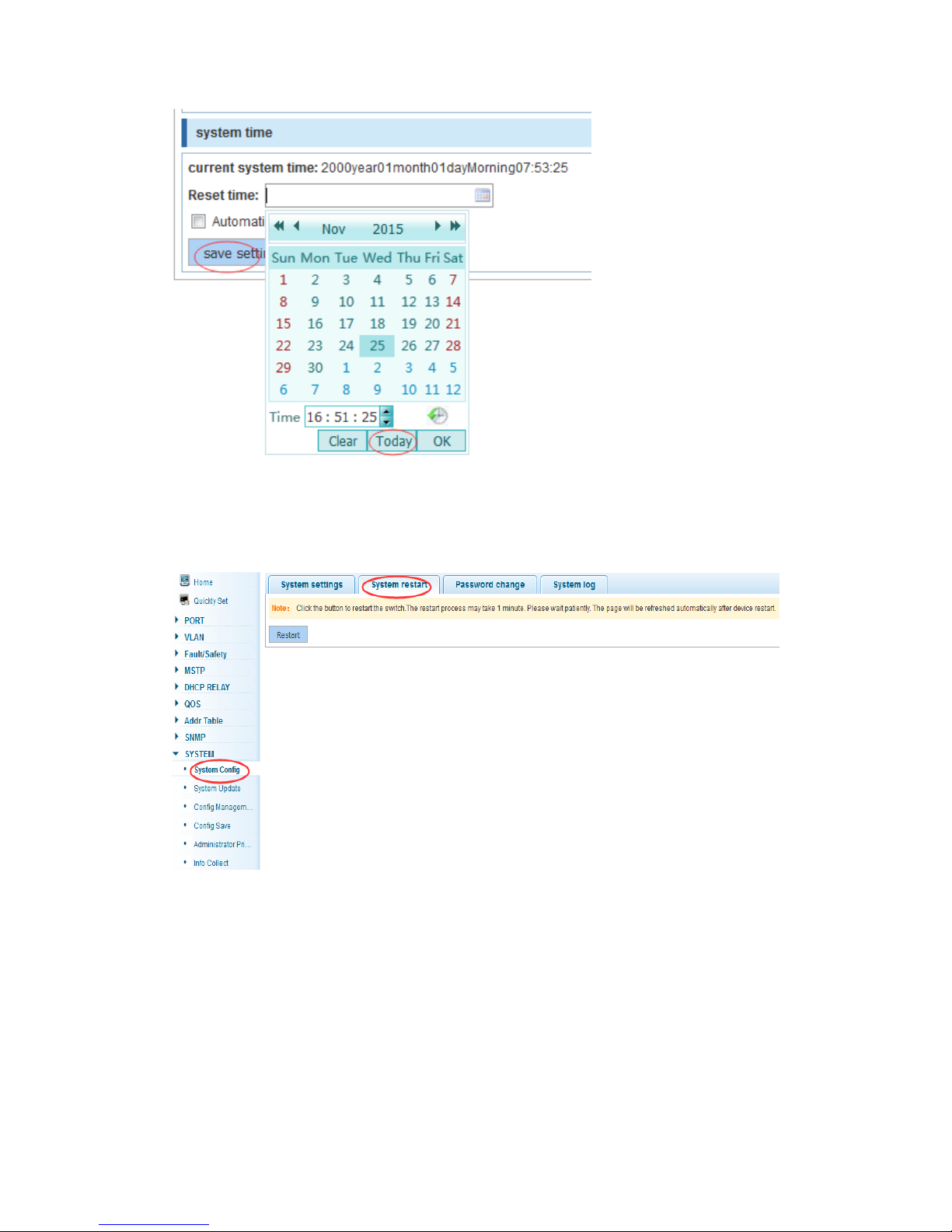
3) Use 192.168.2.12 logging in, sets the system time
Page 67
67
4.10.1.2 System restart
In the navigation bar select “SYSTEM>System Config>System restart”, equipment can
be restarted. As the following picture:
【Instruction】
Click the button to restart the switch. The restart process may take 1 minute. Please wait
patiently. The page will be refreshed automatically after device restart.
【Configuration Example】
Such as: click “restart” button
Page 68
68
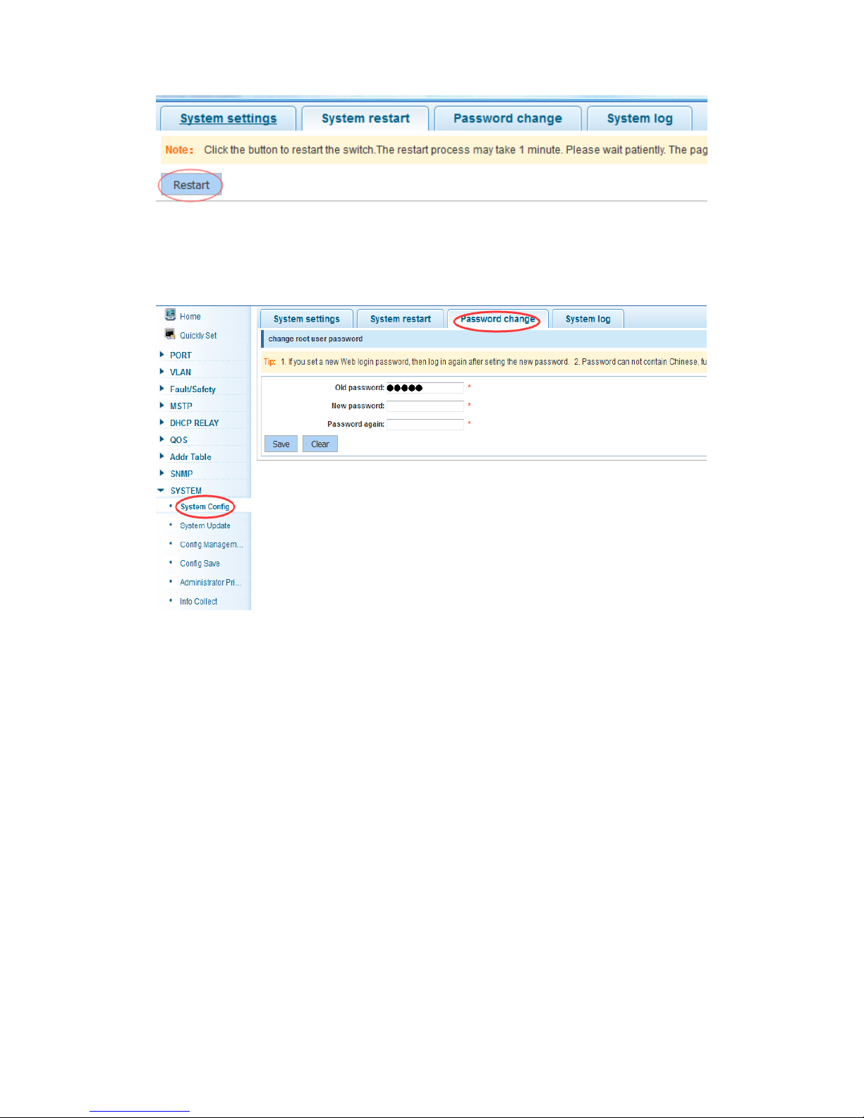
4.10.1.3 Password change
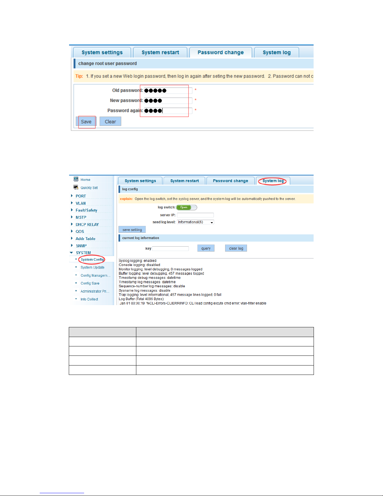
In the navigation bar select “SYSTEM>System Config>Password change”, changing
the password for the equipment. As the following picture
【Instruction】
1. If you set a new Web login password, then log in again after setting the new password.
2. Password can’t contain Chinese, full-width characters, question marks and spaces.
3. If forget the password, can be reset in the console.
switch(config)# password admin
New Password:3456
Confirm Password:3456
【Configuration Example】
Such as: change the password to 1234.
Page 69
69
4.10.1.4 System log
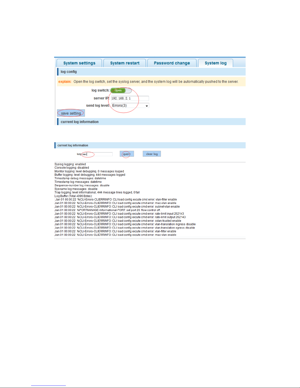
In the navigation bar select “SYSTEM>System Config>System log”, view the log and
set up the log server. As the following picture:
【Parameter Description】
Parameter
Description
Log switch
Open and close
Server ip
Appoint to server address
Send log level
0-7
key
Enter characters for the required query
【Instruction】
Open log switch, set up the syslog server, system log will be pushed to the server
automatically.
Page 70
70
【Configuration Example】
Such as: 1) Pushing the error log information to the server 192.168.2.1
2) Input the keywords “Mac”, click “query” button. Click on the "clear log" button, can clear
the log
4.10.2 System upgrade
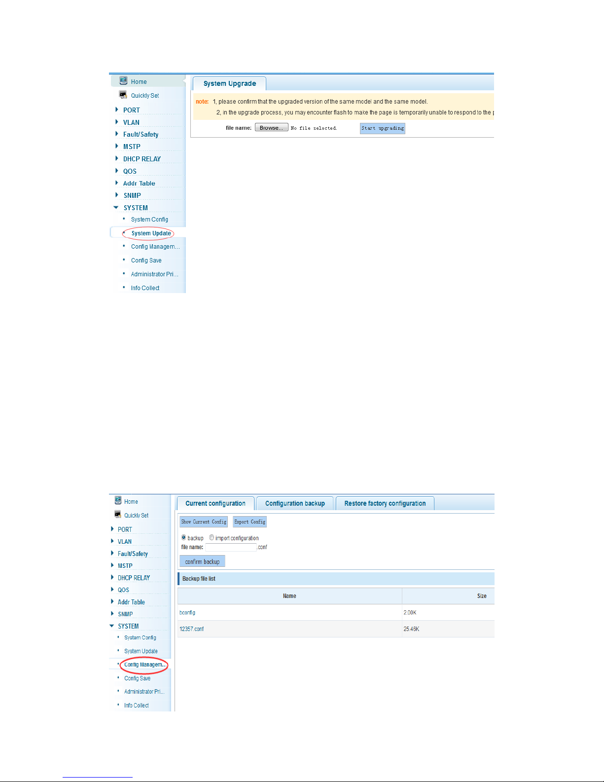
In the navigation bar select “SYSTEM>System Upgrade”, optional upgrade file to
upgrade the system. As the following picture
Page 71
71
【Instruction】
1 Please confirm that the upgrading version is corresponding to the model.
2 In the upgrade process, you may encounter the page is temporarily unable to respond to
the page while arrange flash, at this time cannot power off or restart the device, until
prompted to upgrade successfully.
4.10.3 Config management
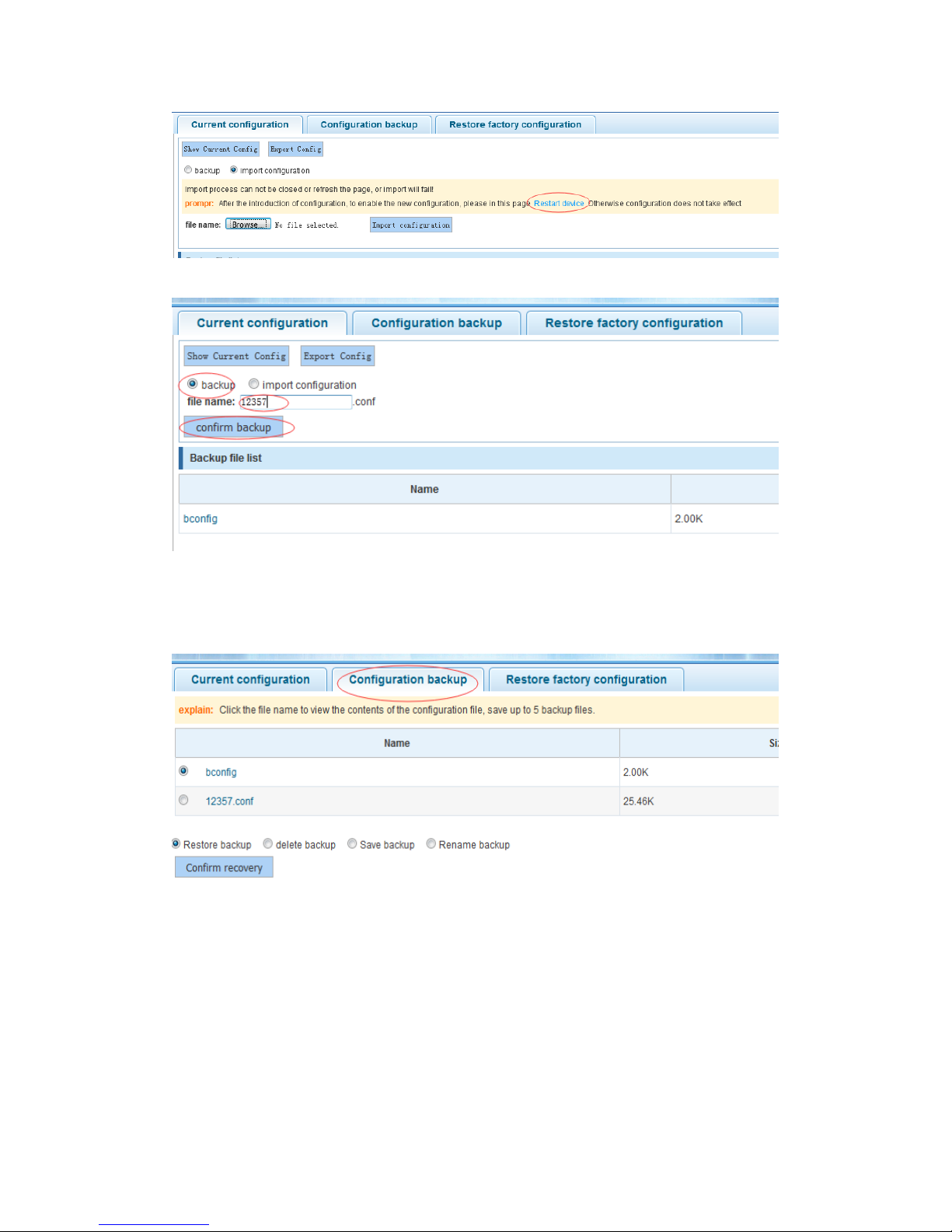
4.10.3.1 Current configuration
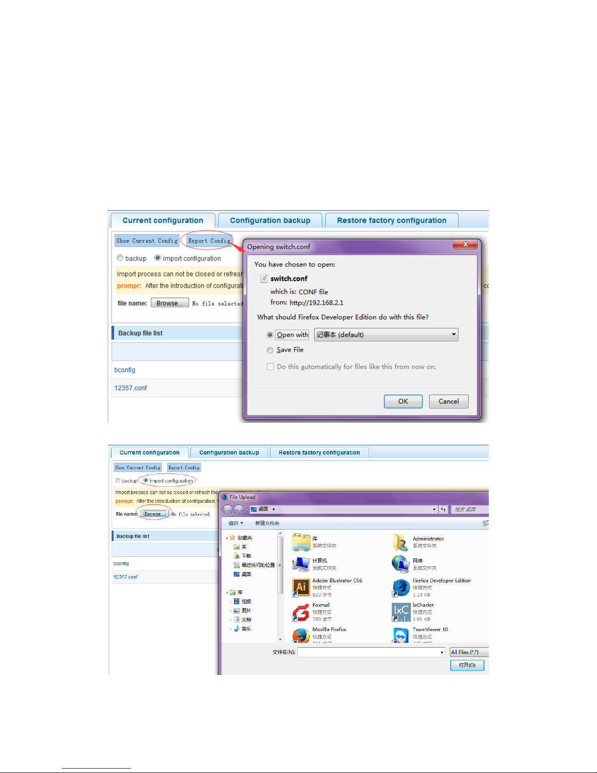
In the navigation bar select “SYSTEM>Config Management>Current configuration”,
can import and export configuration files, and backup the configure file. As the following
picture:
Page 72
72
【Instruction】
Can’t be closed or refresh the page during import process, or import will fail.
After the introduction of configuration, to enable the new configuration, please restart
device in this page otherwise configuration does not take effect.
【Configuration Example】
Such as: 1) Save the page in the configuration first, click save configuration to save the
current configuration, then export the configuration
2) Import configuration
Page 73
73
3)Backup
4.10.3.2 Configuration backup
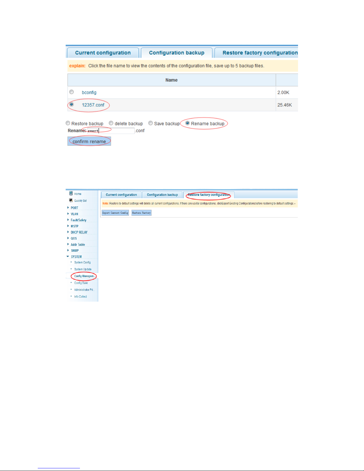
In the navigation bar select “SYSTEM>Config Management>Configuration backup”,
you can configure backup file. As the following picture:
【Instruction】
Operating this page should backup file via the current configuration page first.
【Configuration Example】
Such as: rename backup file
Page 74
74
4.10.3.3 Restore factory configuration
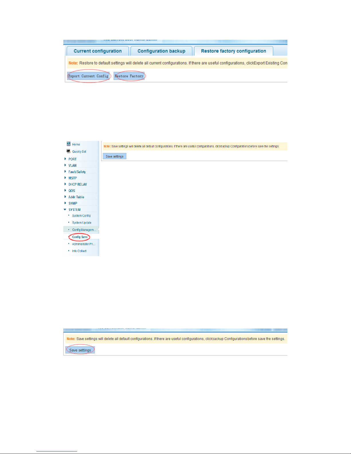
In the navigation bar select “SYSTEM>Config Management>Restore factory
configuraton”, can export the current configuration and restore factory configuration .As
the following picture:
【Instruction】
Restore the factory configuration, will delete all current configuration. If you have
any useful configuration, export the current system before restore factory
configuration!!!
【Configuration Example】
Such as: export the current system before restore factory configuration
Page 75
75
4.10.4 Config save
In the navigation bar select “SYSTEM>Config Save”, you can save current configuration.
As the following picture:
【Instruction】
Save settings will delete all default configurations. If there are useful configurations, click
backup Configurations before save the settings.
【Configuration Example】
Such as: click “save settings” button
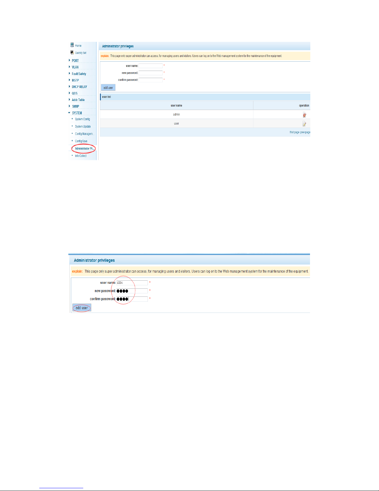
4.10.5 Administrator privileges
In the navigation bar select “SYSTEM>Administrator Privileges”, configure ordinary
users. As the following picture:
Page 76
76
【Instruction】
Only the super administrator with “admin” account can access this page, it’s used to
manage users and visitors. Users can log in the Web management system of equipment
for routine maintenance. Except the “admin” and “user”, there can add five accounts total.
Ordinary users can only access information on system home page.
【Configuration Example】
Such as:
4.10.6 Info collect
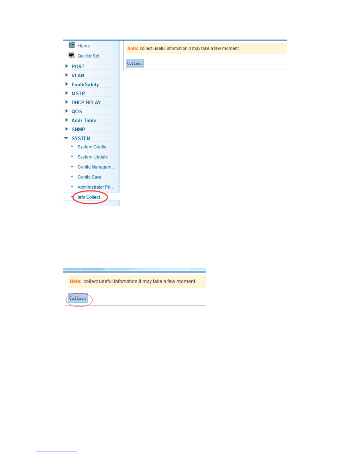
In the navigation bar select “SYSTEM>Info Collect”, you can collect to the system debug
information. As the following picture:
Page 77
77
【Instruction】
It may take a few minutes to collect useful information.
【Configuration Example】
Such as: click on "collect" button
Page 78

78
Appendix: Technical Specifications
Hardware Features
Standards
IEEE 802.3, IEEE 802.3u, IEEE 802.3ab, IEEE 802.3x,
IEEE 802.3z, IEEE 802.3ad
Network Media (Cable)
10BASE-T: UTP category 3, 4, 5 cable (maximum 100m)
100BASE-Tx: UTP category 5, 5e cable (maximum 100m)
1000BASE-T: UTP category 5e, 6 cable (maximum 100m)
Number of Ports
16 x 10/100/1000Mbps Auto-Negotiation ports
2 x SFP ports
1 x Console port
Transfer Method
Store-and-Forward
Switching Capacity
52Gb/s
MAC Address Learning
Automatically learning, automatically update 8K table
Frame Filtering and
Forward Rate
10Mbps: 14880pps
100Mbps: 148800pps
1000Mbps: 1488000pps
Dimensions (L × W × H)
440 x 208 x 44 mm
Environment
Operating Temperature: 0℃~40℃
Storage Temperature: -10℃~70℃
Operating Humidity: 10%~90% non-condensing
Storage humidity: 5%~90% non-condensing
Power Supply
AC 100V~240V 50/60Hz (Internal Power supply)
 Loading...