

Page 1
Comelit Group S.p.A. - Via Don Arrigoni 5 - 24020 Rovetta S. Lorenzo BG Italy - tel. (+39) 0346 750 011 - fax (+39) 0346 71436
www.comelit.eu www.simplehome.eu [email protected] [email protected] [email protected]
Assistenza tecnica Italia 0346/750090
Commerciale Italia 0346/750091
Technical service abroad (+39) 0346750092
Export department (+39) 0346750093
TECHNICAL
SHEET
FOGLIO
TECNICO
FEUILLE
TECHNIQUE
ENIT FR
MT KIT 12
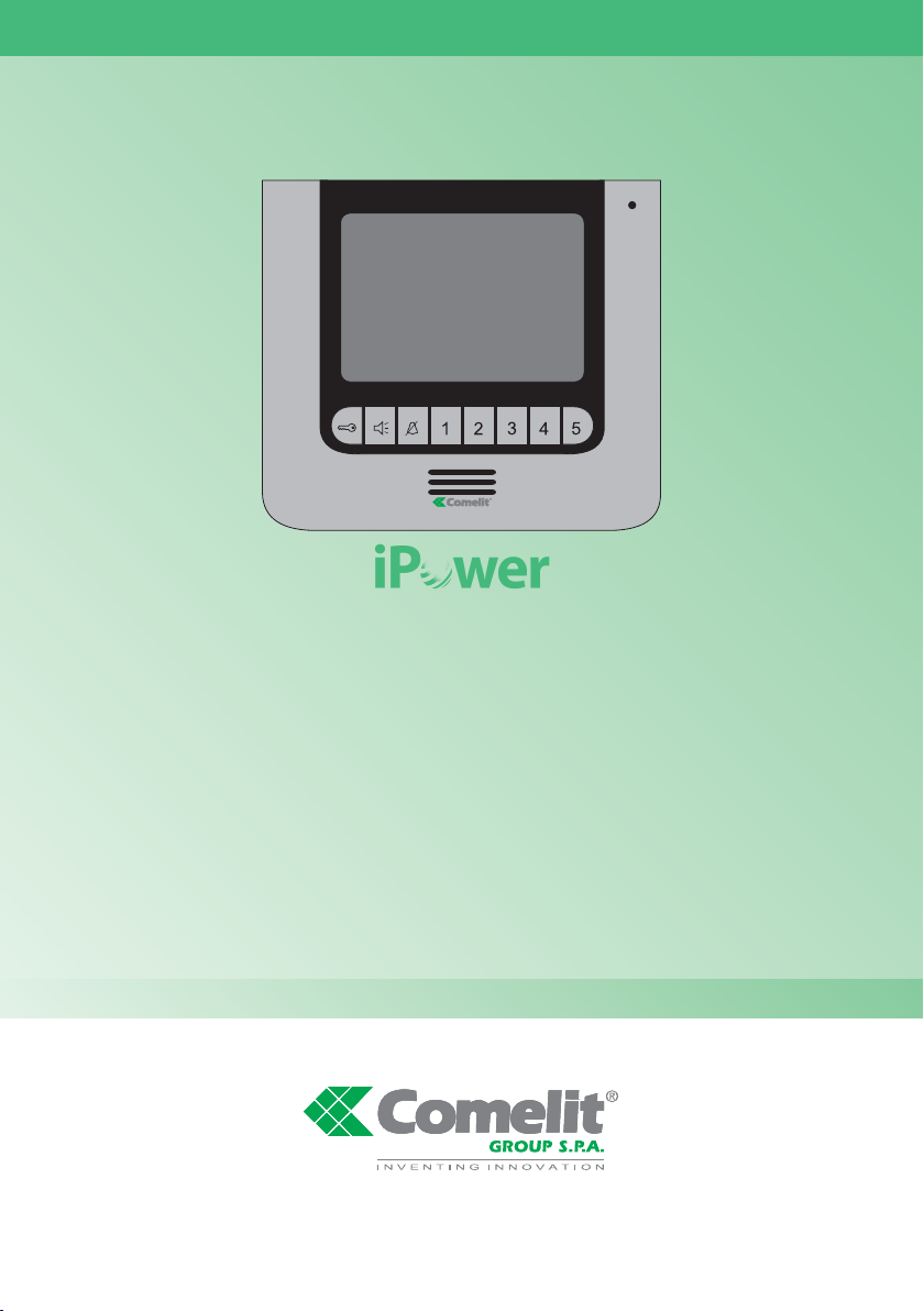
Manuale tecnico installatore iPower kit
Technical installation manual - iPower kit
Manuel technique d’installation iPower kit
Page 2
GROUP S.P.A.
2
MT KIT 12
IT
EN
FR
Warning
• Install the equipment by carefully following the instructions given by the manufacturer and in compliance with the legislation in force.
• All the equipment must only be used for the purpose it was built for. Comelit Group S.p.A. declines any responsibility for improper use of
the apparatus, for modifications made by others under any title or scope, and for the use of accessories and materials which are not the
original ones.
• All the products comply with the requirements of the 2006/95/CE directives (which replace the 73/23/CEE directives and the successive
amendments). This is proved by the CE mark on the products.
Avertissement
• Effectuer l’installation en suivant scrupuleusement les instructions fournies par le constructeur et conformément aux normes en vigueur.
• Tous les appareils doivent être strictement destinés à l’emploi pour lequel ils ont été conçus. Comelit Group S.p.A. décline toute
responsabilité en cas de mauvais usage des appareils, pour des modifications effectuées par d’autres personnes pour n’importe quelle
raison et pour l’ utilisation d’accessoires non fournis par nous.
• Tous les produits sont conformes aux exigences des directives 2006/95/CE (qui remplacent les directives 73/23/CEE et amendements
successifs). Cette conformité est signalée par le symbole CE figurant sur les produits.
Avvertenze
• Effettuare l’installazione seguendo scrupolosamente le istruzioni fornite dal costruttore ed in conformità alle norme vigenti.
• Tutti gli apparecchi devono essere destinati esclusivamente all’uso per cui sono stati concepiti. Comelit Group S.p.A. declina ogni
responsabilità per un utilizzo improprio degli apparecchi, per modifiche effettuate da altri a qualunque titolo e scopo, per l’uso di accessori
e materiali non originali.
• Tutti i prodotti sono conformi alle prescrizioni delle direttive 2006/95/CE (che sostituisce la direttiva 73/23/CEE e successivi emendamenti)
e ciò è attestato dalla presenza della marcatura CE sugli stessi.
Page 3
MT KIT 12
MT KIT 12
3
SOMMARIO
Montaggio telaio posto esterno
1
pag. 6
Cablaggio alimentatore Art. 1397 verso il posto esterno
2
pag. 7
Serrattura in AC (Relé 1)
3A
pag. 8
Serratura in DC (Relé 1)
3B
pag. 9
Comando locale temporizzato serratura (Relé 1)
4
pag. 10
Montaggio e orientamento modulo telecamera
5
pag. 11
Tabella impostazioni Dip switch posto esterno
6
pag. 12
Kit monofamiliare: cablaggio monofase ponte Art. 1398
7A
pag. 13
Kit bifamiliare: cablaggio monofase ponti Art. 1398
7B
pag. 14
Kit bifamiliare con contatore parti comuni: cablaggio monofase ponti Art. 1398
7C
pag. 15
Distanze di collegamento
8
pag. 16
Accensione alimentazione generale
9
pag. 18
Kit monofamiliare: corrispondenza staffa / pulsante di chiamata
10A
pag. 18
Kit bifamiliare: corrispondenza staffa / pulsante di chiamata e alimentatore monitor / ponte Art. 1398
10B
pag. 19
Montaggio monitor
11
pag. 20
Segnalazione anomalie e possibili soluzioni
12
pag. 21
Utilizzo relé del modulo numero civico (Relé 2)
13
pag. 22
Installazione monitor supplementari secondari (MAX 14)
14
pag. 23
Abilitare e disabilitare il menu installatore
15
pag. 25
Impostazione lingua menu
16
pag. 26
Accedere al menu installatore
17
pag. 26
Descrizione menu installatore
18
pag. 26
Descrizione icone abbinate ai pulsanti
19
pag. 26
Configurazione password modem
20
pag. 27
Segnalazione anomalie e possibili soluzioni
21
pag. 28
Configurazione pulsanti
22
pag. 28
Attivazione ripetizione suoneria
23
pag. 31
Attivazione risposta automatica
24
pag. 31
Visualizza informazioni
25
pag. 32
Configurazione tempi di chiamata
26
pag. 32
Reset configurazione
27
pag. 33
Menu imposta tipo di rete
28
pag. 33
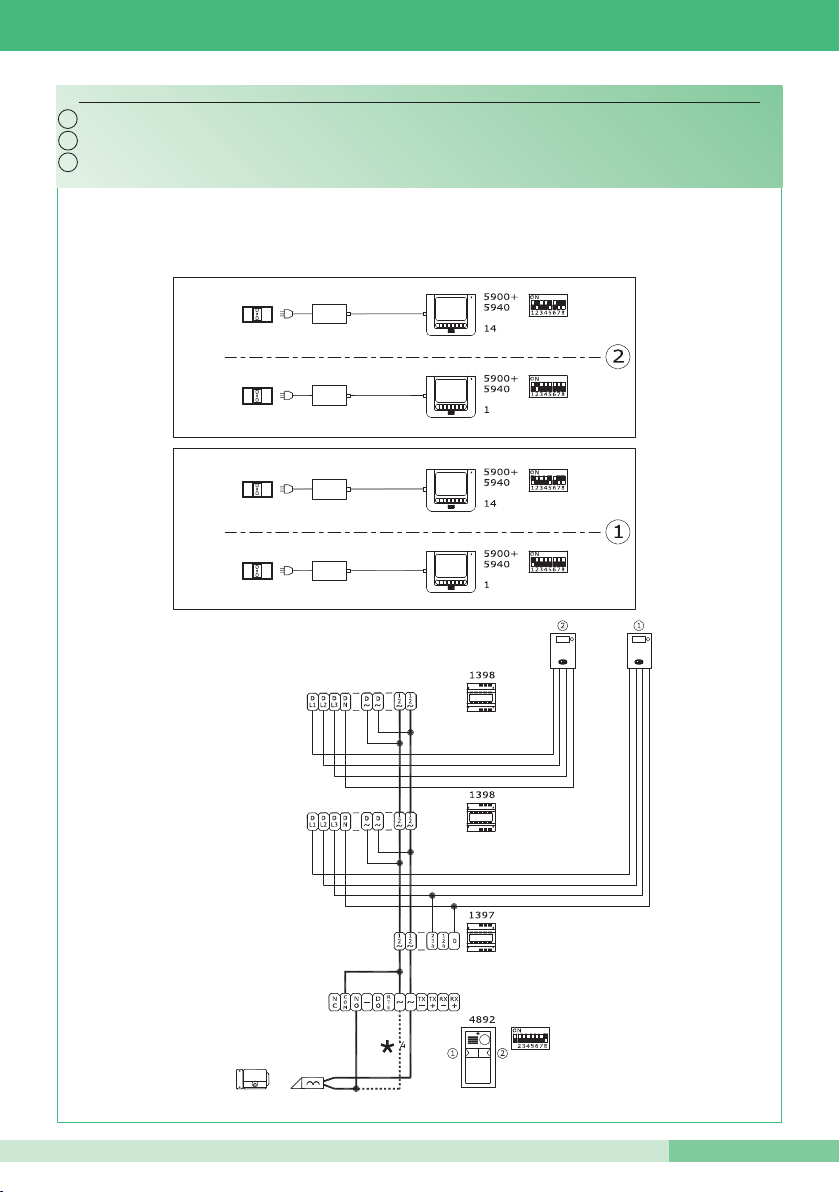
Schema PWK/01A: Cablaggio kit monofamiliare Art. 8591 pag. 50
Schema PWK/05: Calaggio kit monofamiliare trifase Art. 8591 pag. 51
Schema PWK/02A:
Cablaggio kit bifamiliare Art. 8592 pag. 52
Schema PWK/06: Cablaggio kit bifamiliare trifase Art. 8592 pag. 53
Schema PWK/02B: Cablaggio kit bifamiliare Art. 8592 con contatore parti comuni pag. 54
Schema PWK/01B: Cablaggio kit monofamiliare con alimentatore supplementare per posto esterno pag. 55
Schema PWK/03: Cablaggio kit monofamiliare con 2 posti esterni pag. 56
Schema PWK/04: Cablaggio kit bifamiliare con 2 posti esterni pag. 57
Variante PW/AAA: collegamento relé del modulo numero civico (relé 2) pag. 58
Variante PW/AAB: collagamento relé temporizzato pag. 58
Variante PW/AAC: contatto segnalazione porta aperta pag. 59
Variante per utilizzo rete RC per filtro serratura sui contatti del relé 1 o relé 2 pag. 59
Page 4
GROUP S.P.A.
4
MT KIT 12
CONTENTS
Installing the external unit frame
1
Page 6
Wiring between power supply Art. 1397 and the external unit
2
Page 7
AC door-release (Relay 1)
3A
Page 8
DC door-release (Relay 1)
3B
Page 9
Timed local door-release command (Relay 1) (RTE)
4
Page 10
Installing and adjusting the direction of the camera
5
Page 11
Table of external unit Dip switch settings
6
Page 12
Single-residence kit: Single-phase wiring for bridge Art. 1398
7A
Page 13
Two-residence kit: Single-phase wiring for bridges Art. 1398
7B
Page 14
Two-residence kit with shared parts meter: Single-phase wiring for bridges Art. 1398
7C
Page 15
Connection distances
8
Page 16
Switching on the main power supply
9
Page 18
Single-residence kit: bracket / call pushbutton alignment
10A
Page 18
Two-residence kit: bracket / call pushbutton and monitor power supply / bridge Art. 1398 alignment
10A
Page 19
Installing the monitor
11
Page 20
Fault indication and troubleshooting
12
Page 21
Using the house number module relay (Relay 2)
13
Page 22
Installing additional secondary monitors (MAX 14)
14
Page 23
Enabling and disabling the installer menu
15
Page 25
Setting the menu language
16
Page 34
Entering the installer menu
17
Page 34
Description of the installer menu
18
Page 34
Description of the icons corresponding to the pushbuttons
19
Page 34
Setting the modem password
20
Page 35
Fault indication and troubleshooting
21
Page 36
Programming the pushbuttons
22
Page 36
Activating ringtone repetition
23
Page 39
Activating the automatic response
24
Page 39
Displaying information
25
Page 40
Programming call times
26
Page 40
Reset configuration
27
Page 41
Select type of network menu
28
Page 41
Diagram PWK/01A: Wiring for single-residence kit Art. 8591 Page 50
Diagram PWK/05: Wiring for three-phase single-residence kit Art. 8591 Page 51
Diagram PWK/02A:
Wiring for two-residence kit Art. 8592 Page 52
Diagram PWK/06: Wiring for three-phase two-residence kit Art. 8592 Page 53
Diagram PWK/02B: Wiring for two-residence kit Art. 8592 with shared parts meter Page 54
Diagram PWK/01B: Wiring for single-residence kit with additional external unit power supply Page 55
Diagram PWK/03: Wiring for single-residence kit with 2 external units Page 56
Diagram PWK/04: Wiring for two-residence kit with 2 external units Page 57
PW/AAA variant: house number module relay connection (relay 2) Page 58
PW/AAB variant: timed relay connection Page 58
PW/AAC variant: door open indication contact Page 59
Variant using RC network for door-release filter on relay 1 or relay 2 contacts Page 59
Page 5
MT KIT 12
MT KIT 12
5
SOMMAIRE
Montage châssis plaque de rue
1
page. 6
Câblage alimentateur Art. 1397 vers la plaque de rue
2
page. 7
Gâche en C.A. (relais 1)
3A
page. 8
Gâche en C.C. (relais 1)
3B
page. 9
Commande locale temporisée gâche (relais 1)
4
page. 10
Montage et orientation module caméra
5
page. 11
Tableau réglages Dip switches plaque de rue
6
page. 12
Kit un appartement : câblage monophasé pont Art. 1398
7A
page. 13
Kit deux appartements : câblage monophasé ponts Art. 1398
7B
page. 14
Kit deux appartements avec compteur parties communes : câblage monophasé ponts Art. 1398
7C
page. 15
Distances de connexion
8
page. 16
Allumage alimentation générale
9
page. 18
Kit un appartement : correspondance bride / touche d’appel
10A
page. 18
Kit deux appartements : correspondance bride / touche d’appel et alimentateur moniteur / pont Art. 1398
10B
page. 19
Montage moniteur
11
page. 20
Signalisation anomalies et solutions possibles
12
page. 21
Utilisation relais du module numéro de rue
13
page. 22
Installation moniteurs supplémentaires secondaires
14
page. 23
Valider et invalider le menu d’installation
15
page. 25
Réglage langue menu
16
page 42
Accéder au menu d’installation
17
page 42
Description menu d’installation
18
page 42
Description icônes associées aux touches
19
page 42
Configuration mot de passe modem
20
page 43
Signalisation anomalies et solutions possibles
21
page 44
Configuration touches
22
page 44
Activation répétition sonnerie
23
page 47
Activation réponse automatique
24
page 47
Visualiser informations
25
page 48
Configuration temps d’appel
26
page 48
Reset configuration
27
page 49
Menu programmation type de réseau
28
page 49
Schéma PWK/01A : Câblage kit un appartement Art. 8591 page 50
Schéma PWK/05 : Câblage kit un appartement triphasé Art. 8591 page 51
Schéma PWK/02A :
Câblage kit deux appatements Art. 8592 page 52
Schéma PWK/06 : Câblage kit deux appartements triphasé Art. 8592 page 53
Schéma PWK/02B : Câblage kit deux appartements Art. 8592 avec compteur pour parties communes page 54
Schéma PWK/01B : Câblage kit un appartement avec alimentateur supplémentaire pour plaque de rue page 55
Schéma PWK/03 : Câblage kit un appartement avec 2 plaques de rue page 56
Schéma PWK/04 : Câblage kit deux appartements avec 2 plaques de rue page 57
Variante PW/AAA : connexion relais du module numéro de rue (relais 2) page 58
Variante PW/AAB : connexion relais temporisé page 58
Variante PW/AAC : contact signalisation porte ouverte page 59
Variante pour emploi réseau RC pour filtre gâche sur ontacts du relais 1 ou relais 2 page 59
Page 6
GROUP S.P.A.
6
MT KIT 12
IT
EN
FR
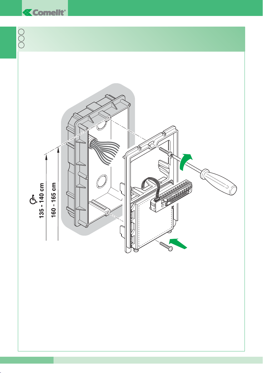
1
Montaggio telaio posto esterno.
Installing the external unit frame.
Montage châssis plaque de rue.
Page 7
MT KIT 12
MT KIT 12
7
IT
EN
FR
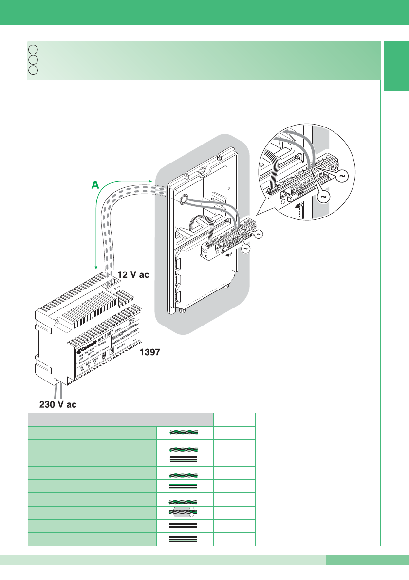
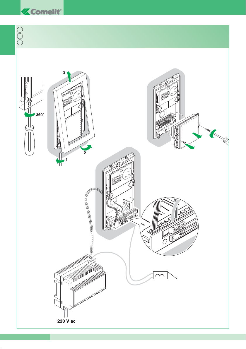
2
A Max
0,28 mm2 (Ø 0,6 mm - Ø 6/10 AWG 23)
0,2 mm2(Ø 0.5 mm AWG 24)
0,5 mm2(Ø 0.8 mm AWG 20)
10 m
0,5 mm2(Ø 0.8 mm AWG 20)
10 m
1 mm2(Ø 1,2 mm AWG 17)
25 m
1 mm2(Ø 1.2 mm AWG 17)
25 m
1 mm2(Ø 1.2 mm AWG 17)
25 m
1,5 mm2(Ø 1,4 mm AWG 15)
40 m
2,5 mm2(Ø 1,8 mm AWG 13)
60 m
UTP5 cat. 5
Comelit Art. 4576-4578
Comelit Art. 4577
Cablaggio alimentatore Art. 1397 verso il posto esterno.
Wiring between power supply Art. 1397 and the external unit.
Câblage alimentateur Art. 1397 vers la plaque de rue.
Page 8
GROUP S.P.A.
8
MT KIT 12
IT
EN
FR
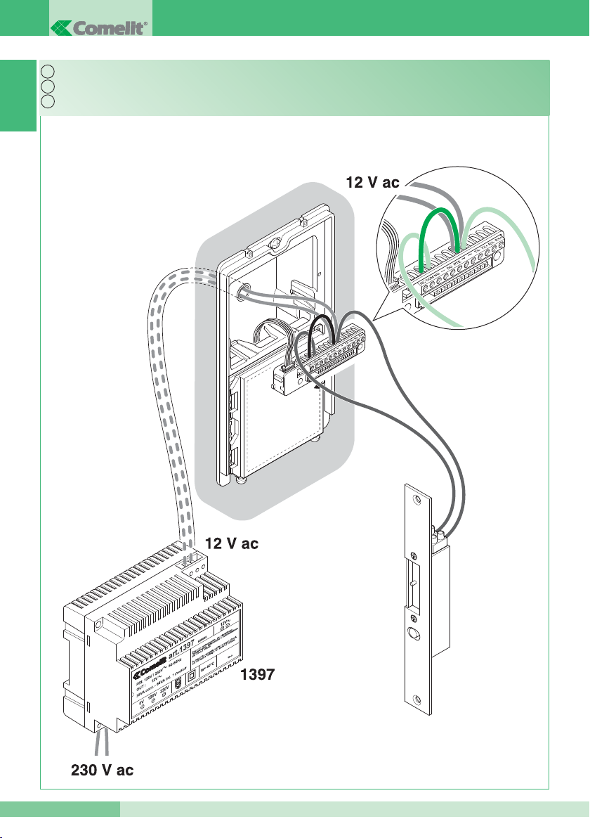
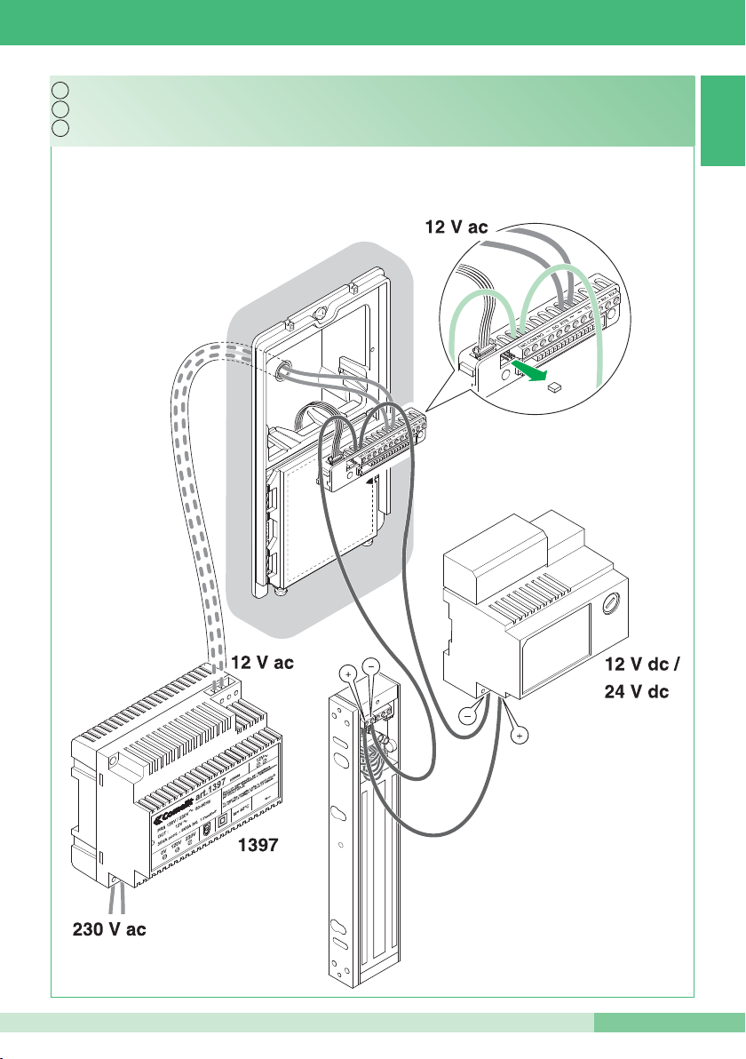
3A
Serratura in AC (Relé 1).
AC door-release (Relay 1).
Gâche en C.A. (Relais 1).
Page 9
MT KIT 12
MT KIT 12
9
IT
EN
FR
3B
Serratura in DC (Relé 1).
DC door-release (Relay 1).
Gâche en C.C. (Relais 1).
Page 10
GROUP S.P.A.
10
MT KIT 12
IT
EN
FR
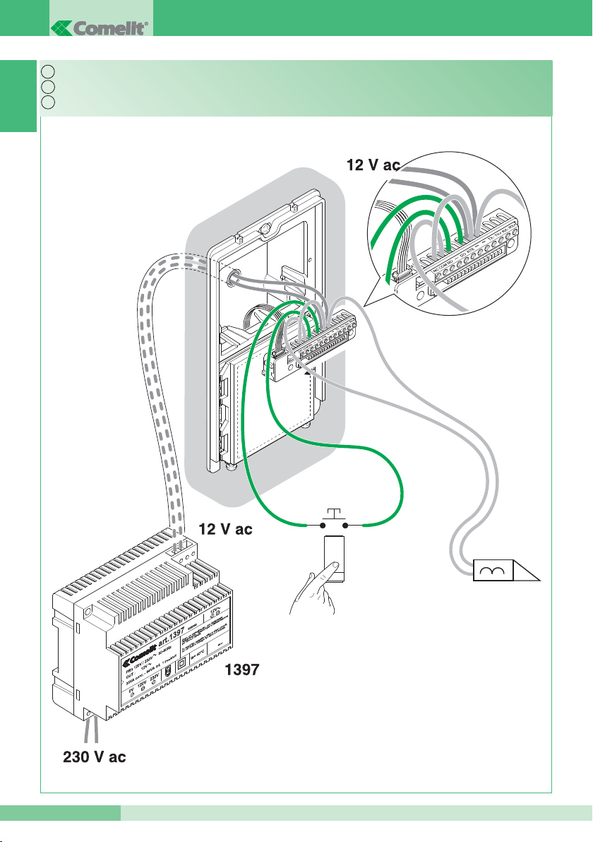
4
Comando locale temporizzato serratura (Relé 1).
Timed local door-release command (Relay 1) (Request to exit).
Commande locale temporisée gâche (Relais 1).
Page 11
MT KIT 12
MT KIT 12
11
1
23
4
5
6
78
O
N
DIP
IT
EN
FR
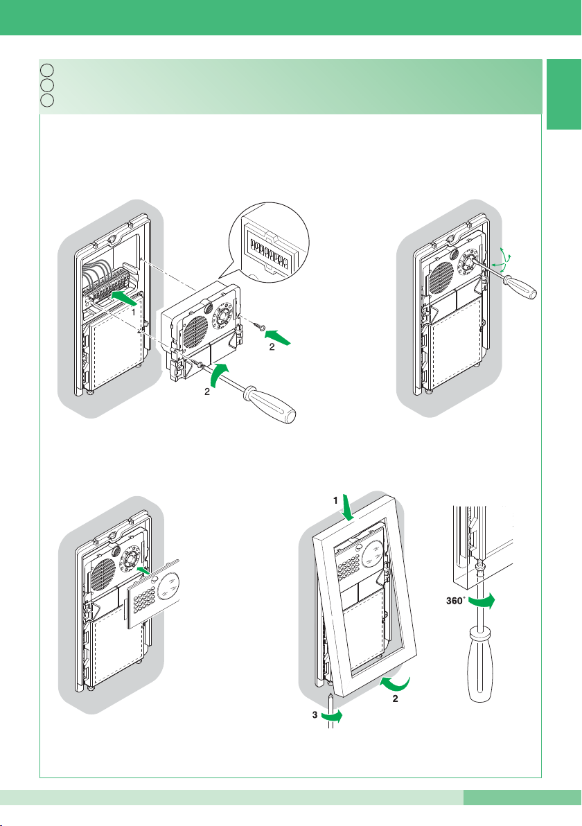
5
Vedi punto 6
Montaggio e orientamento modulo telecamera.
Installing and adjusting the direction of the camera.
See paragraph 6
Voir point 6
Montage et orientation module caméra.
Page 12
GROUP S.P.A.
12
MT KIT 12
DIP
OFF
ON
1
Identificazione del posto esterno
Identifying external unit
Identification de la plaque de rue
Posto esterno 1
External unit 1
Plaque de rue 1
Posto esterno 2
External unit 2
Plaque de rue 2
4
Utilizzo relé 2 (vedi punto 13)
Using relay 2 (see paragraph 13)
Utilisation relais 2 (voir point 13)
Si attiva solo su comando da staffa
Only activated on a command from the
bracket
S’active uniquement sur commande par
bride
Si attiva anche automaticamente* su chiamata da posto esterno e autoaccensione
Also activated automatically* on receipt of a call from the external unit and when the self-
ignition function is enabled
S’active également automatiquement* sur appel depuis la plaque de rue et auto-allumage
5
Tempo attivazione relé 1 (vedi punto 13)
Relay 1 activation time
(see paragraph 13)
Temps activation relais 1 (voir point 13)
2 secondi
2 seconds
2 secondes
8 secondi
8 seconds
8 secondes
6
Tempo attivazione relé 2 (vedi punto 13)
Relay 2 activation time
(see paragraph 13)
Temps activation relais 2 (voir point 13)
2 secondi; *(1 minuto se dip 4 ON)
2 seconds; *(1 minute if
Dip switch 4 ON)
2 secondes ; *(1 minute si dip 4 ON)
8 secondi; *(3 minuti se dip 4 ON)
8 seconds; *(3 minutes if Dip switch 4 ON)
8 secondes ; *(3 minutes si dip 4 ON)
7
Tono conferma apri porta
Door open confirmation tone
Tonalité confirmation ouvre porte
Non attivo
Not active
Non actif
Attivo
Active
Actif
8
Tono conferma inizio e fine chiamata
Call start and end confirmation tone
Tonalité confirmation début et fin appel
Non attivo
Not active
Non actif
Attivo
Active
Actif
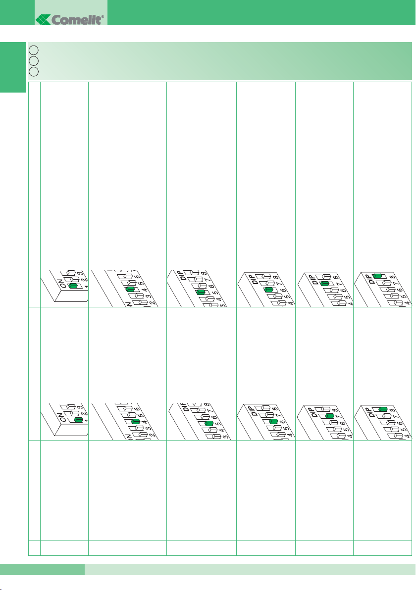
6
IT
EN
FR
Tabella impostazioni dip switch posto esterno
Table of external unit Dip switch settings.
Tableau réglages Dip switches plaque de rue
Page 13
MT KIT 12
MT KIT 12
13
IT
EN
FR
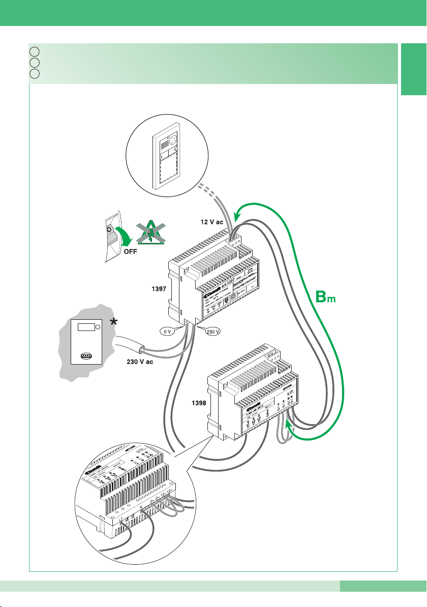
7A
*Bm Max see paragraph 8
*Bm Max voir point 8
* Contatore
*Bm Max vedi punto 8
* Contatore
Kit monofamiliare: cablaggio monofase ponte Art. 1398.
* Meter
Single-residence kit: Single-phase wiring for bridge Art. 1398.
* Compteur
Kit un appartement : cablâge monophasé pont Art. 1398.
Page 14
GROUP S.P.A.
14
MT KIT 12
12~
D
~
D~
L1
N
12
~
IT
EN
FR
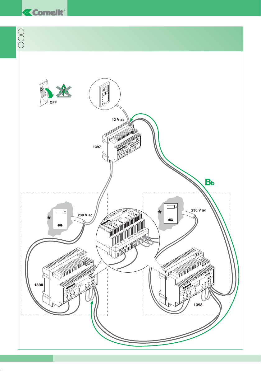
7B
*Bb Max vedi punto 8
* Contatore
Kit bifamiliare: cablaggio monofase ponti Art. 1398.
*Bb Max see paragraph 8
* Meter
Two-residence kit: Single-phase wiring for bridges Art. 1398.
*Bb Max voir point 8
* Compteur
Kit deux appartements : cablâge monophasé ponts Art. 1398.
Page 15
MT KIT 12
MT KIT 12
15
12~
D
~ D~
L
1
N
1
2~
IT
EN
FR
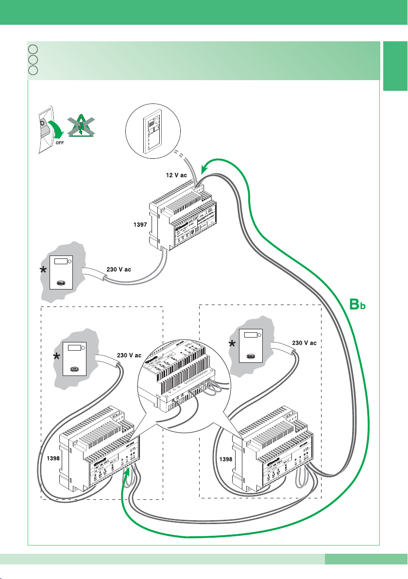
7C
Kit bifamiliare con contatore parti comuni: cablaggio monofase ponti Art. 1398.
* Contatore
* Meter
Two-residence kit with shared parts meter: Single-phase wiring for bridges Art. 1398.
Kit deux appartements avec compteur parties communes: câblage monophasé ponts Art. 1398.
* Compteur
*Bb Max vedi punto 8
*Bb Max see paragraph 8
*Bb Max voir point 8
Page 16
GROUP S.P.A.
16
MT KIT 12
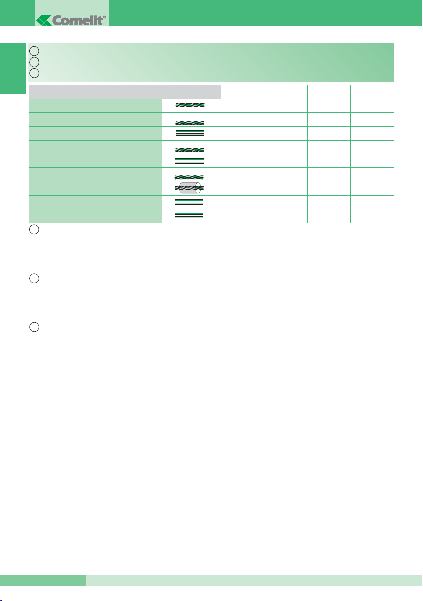
A Max Bm Max Bb Max C Max
0,28 mm2 (Ø 0,6 mm - Ø 6/10 AWG 23) 200 m
0,2 mm2(Ø 0.5 mm AWG 24) 400 m
0,5 mm2(Ø 0.8 mm AWG 20)
10 m
130 m 60 m A + B
0,5 mm2(Ø 0.8 mm AWG 20)
10 m
150 m 70 m 450 m
1 mm2(Ø 1,2 mm AWG 17)
25 m
150 m 70 m 150 m
1 mm2(Ø 1.2 mm AWG 17)
25 m
150 m 70 m 350 m
1 mm2(Ø 1.2 mm AWG 17)
25 m
100 m 50 m A + B
1,5 mm2(Ø 1,4 mm AWG 15)
40 m
160 m 80 m A + B
2,5 mm2(Ø 1,8 mm AWG 13)
60 m
180 m 110 m A + B
IT
EN
FR
8
IT
EN
FR
UTP5 cat. 5
Comelit Art. 4576-4578
Comelit Art. 4577
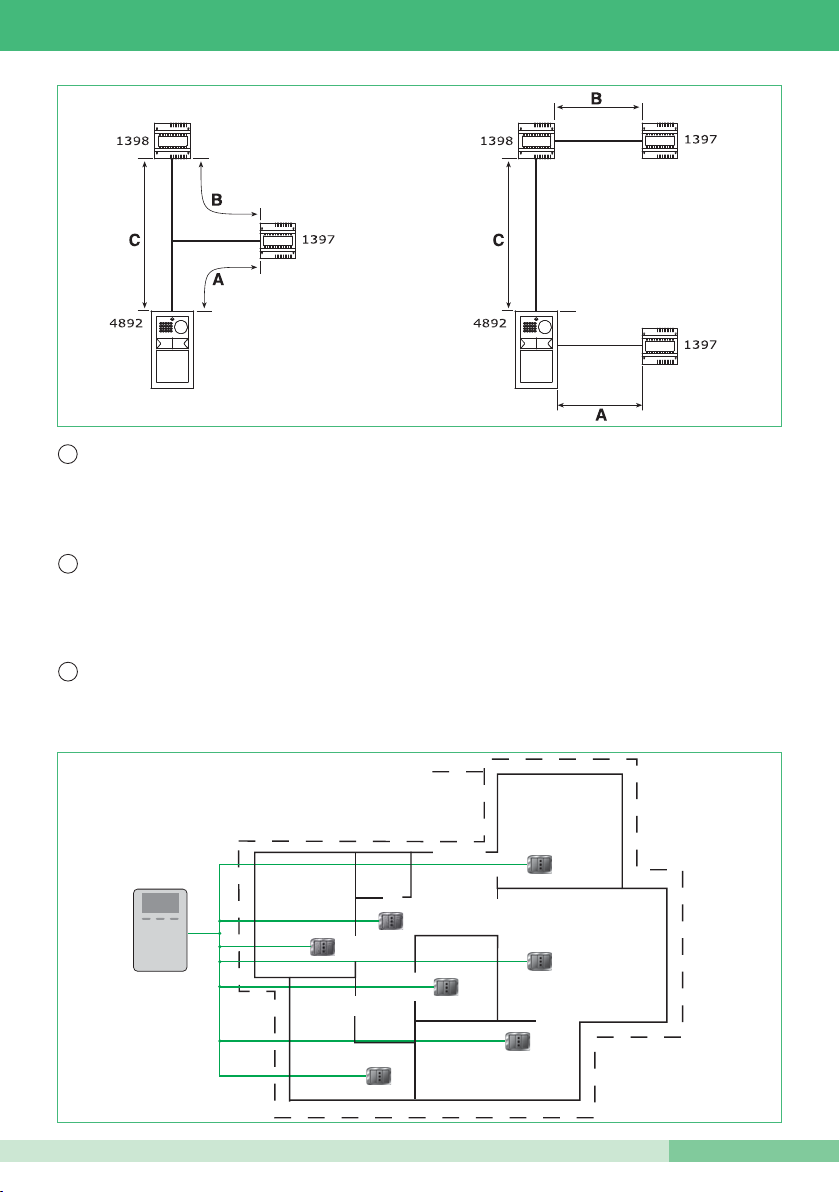
Distanze di collegamento
A: distanza valida con carico massimo di 2 posti esterni, 2 ponti Art. 1398 e l’attivazione di una sola serratura
per volta tra quelle alimentate dall’Art. 1397.
La distanza raddoppia se la serratura è alimentata in modo indipendente.
Bm: Kit monofamiliare (1 ponte Art. 1398)
Bb: kit bifamiliare (2 ponti Art. 1398)
Connection distances.
A: distance applies with a maximum load of 2 external units, 2 bridges Art. 1398 and the activation of only one
door-release device at a time for those powered by Art. 1397.
The distance doubles if the door-release device is powered independently.
Bm: single-residence kit (1 bridge Art. 1398).
Bb: two-residence kit (2 bridges Art. 1398).
Distances de connexion
A: distance valable avec charge maximum de 2 plaques de rue, 2 ponts Art. 1398 et l’activation d’une seule
gâche à la fois parmi celles alimentées par l’Art. 1397.
La distance double si la gâche est alimentée de manière indépendante.
Bm : Kit un appartement (1 pont Art. 1398)
Bb : kit deux appartements (2 ponts Art. 1398)
Page 17
MT KIT 12
MT KIT 12
17
IT
EN
FR
MAX 300 m
2
Attenzione! I gruppi di continuità impediscono il passaggio del segnale. L’insieme di tutti i punti di connessione
(prese elettriche e ponti Art. 1398) utilizzabili per il sistema deve trovarsi in ingresso o in uscita del gruppo di
continuità
* Ambiente residenziale monofase o trifase (non adatto per impianti industriali e alberghieri).
Estensione massima unità abitativa * servita dal ponte Art. 1398: 300m
2
circa.
* Single-phase or three-phase residential installation (not suitable for industrial or hotel systems).
Maximum expanse of residential unit * served by bridge Art. 300m
2
approx.
Caution! Uninterruptible power supplies prevent the signal from passing through. All connection points (electrical
sockets and bridges Art. 1398) which may be used by the system should be positioned at the input or the output
of the uninterruptible power supply.
* Milieu résidentiel monophasé ou triphasé (non adapté aux installations industrielles et hôtelières).
Extension maximum habitation * servie par le pont Art. 1398: 300m
2
environ.
Attention ! Les onduleurs empêchent le passage du signal. L’ensemble de tous les points de connexion (prises
électriques et ponts Art. 1398) utilisables pour le système doit se trouver en entrée ou en sortie de l’onduleur
Page 18
GROUP S.P.A.
18
MT KIT 12
IT
EN
FR
IT
EN
FR
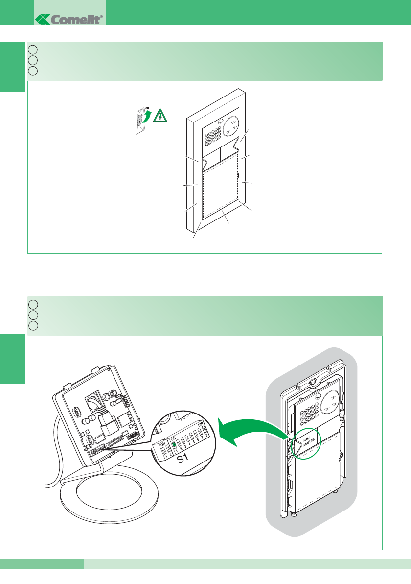
10A
9
Kit monofamiliare: corrispondenza staffa / pulsante di chiamata.
Accensione alimentazione generale.
Single-residence kit: bracket / call pushbutton alignment.
Switching on the main power supply.
Kit un appartement : correspondance bride / touche d’appel.
Allumage alimentation générale.
Page 19
MT KIT 12
MT KIT 12
19
IT
EN
FR
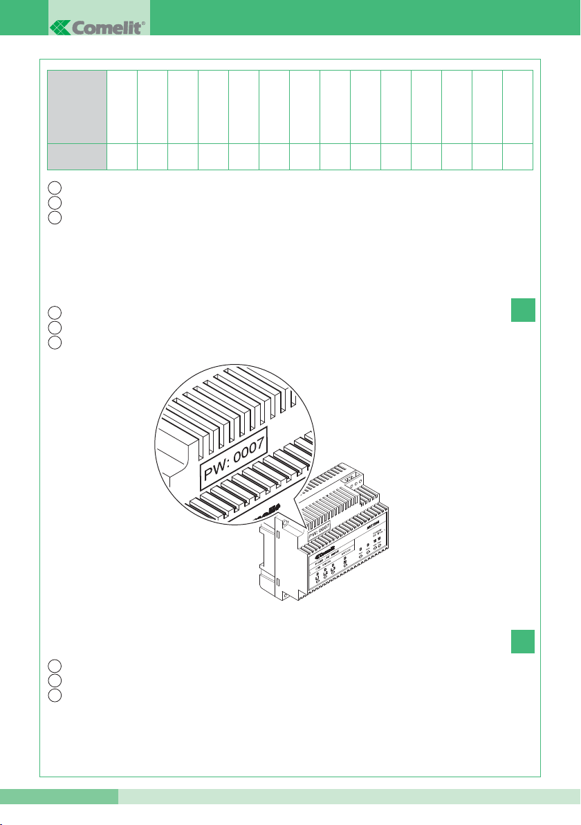
PW: 0004
PW: 0004
PW: 0007
PW: 0007
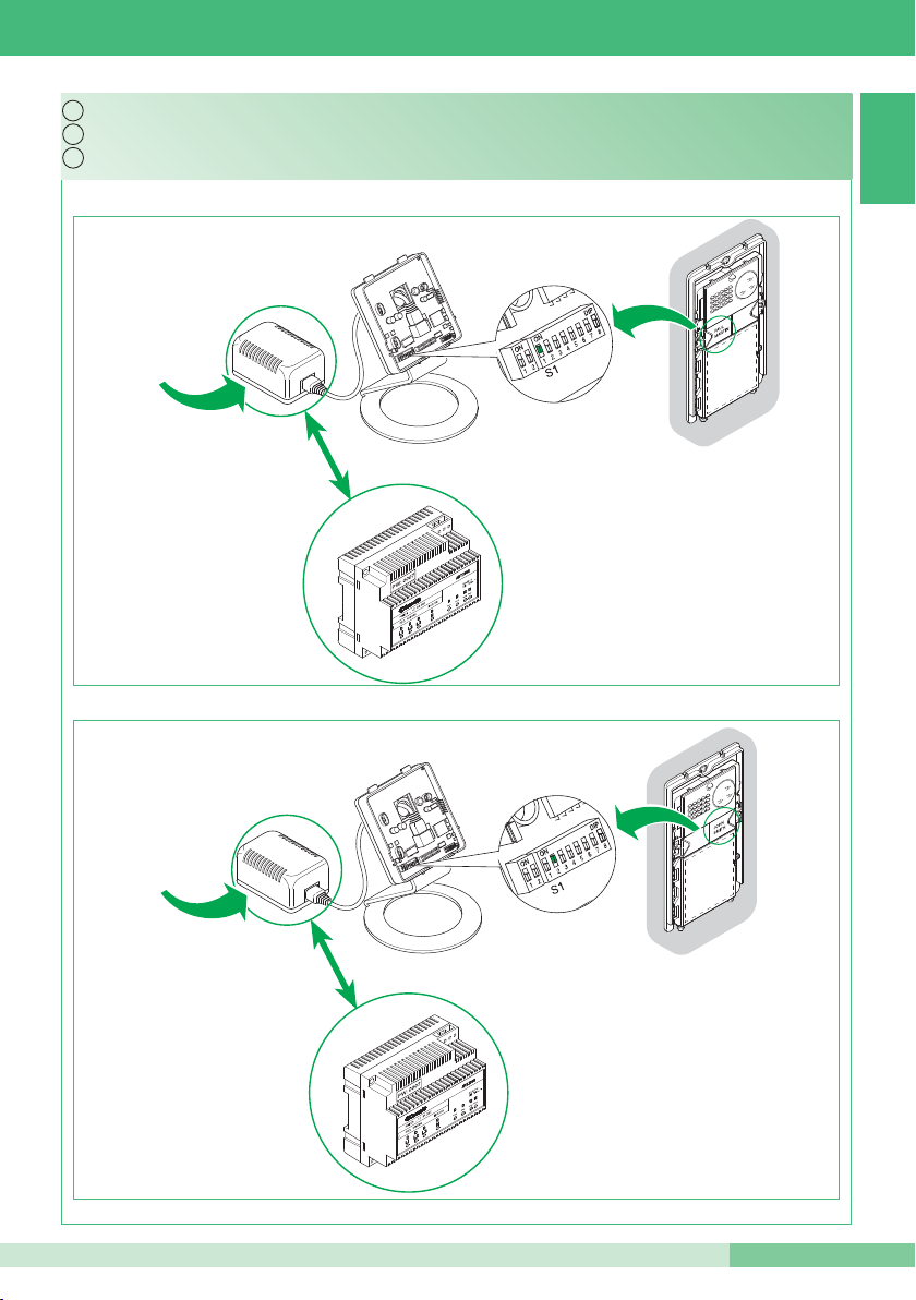
10B
Esempio
Kit bifamiliare: corrispondenza staffa / pulsante di chiamata e alimentatore monitor / ponte Art. 1398
Two-residence kit: bracket / call pushbutton and monitor power supply / bridge Art. 1398 alignment.
Example
Kit deux appartements : correspondance bride / touche d’appel et alimentateur moniteur / pont Art. 1398
Exemple
Esempio
Example
Exemple
Esempio
Example
Exemple
Esempio
Example
Exemple
Page 20
GROUP S.P.A.
20
MT KIT 12
IT
EN
FR
IT
EN
FR
1
1
1
2
2
1
2
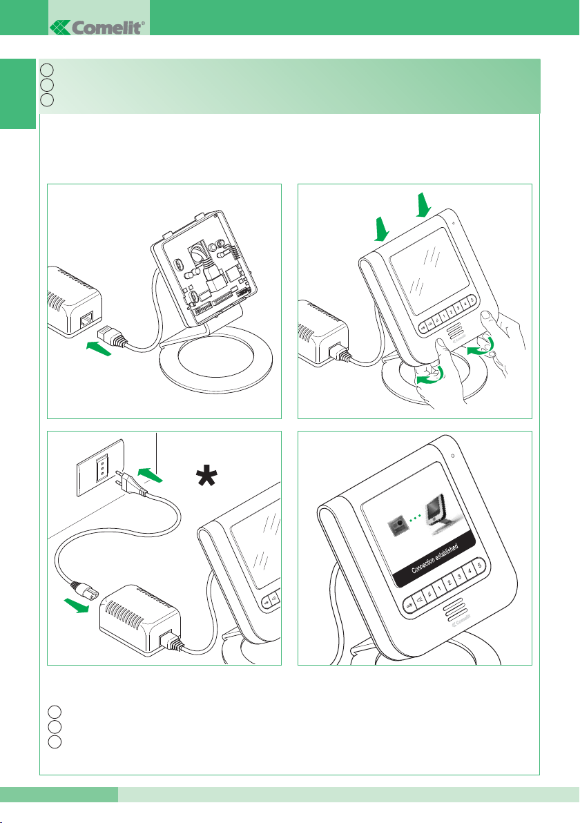
11
Montaggio monitor.
* Non utilizzare ciabatte con interruttore
* Do not use power strips fitted with switches
Installing the monitor.
* Ne pas utiliser des blocs ménagers avec interrupteur
Montage moniteur.
Page 21
MT KIT 12
MT KIT 12
21
IT
EN
FR
IT
EN
FR
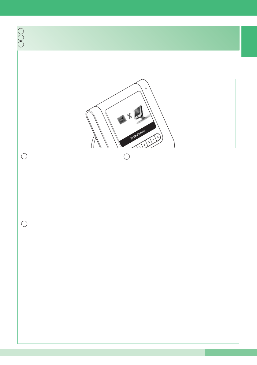
12
In caso di connessione mancante attendere 1
minuto. Se la segnalazione si ripresenta
assicurarsi:
• Che il posto esterno sia correttamente cablato
(punto 2) e che sia alimentato (punto 9).
• Che il ponte Art. 1398 sia correttamente cablato
(punto 7A, 7B o 7C).
• Che ci sia corrispondenza tra la password del
ponte Art. 1398 e l’alimentatore monitor della
stessa unità abitativa.
• Che siano rispettate le distanze di installazione
(punti 2 e 8).
Segnalazione anomalie e possibili soluzioni.
If there is no connection, wait for 1 minute. If the
indication appears again, make sure:
• That the external unit is wired correctly (paragraph
2) and that it is receiving power (paragraph 9).
• That the bridge Art. 1398 is wired correctly
(paragraph 7A, 7B or 7C).
• That the password for bridge Art. 1398 is the
same as the password for the power supply of the
monitor in the same residential unit.
• That the installation distances have been
observed (paragraphs 2 and 8).
Fault indication and troubleshooting.
Signalisation anomalies et solutions possibles.
En cas d’absence de connexion, attendre 1
minute Si la signalisation se présente à nouveau,
vérifier :
• que la plaque de rue est correctement câblée
(point 2) et qu’elle est alimentée (point 9).
• que le pont Art. 1398 est correctement câblé
(point 7A, 7B ou 7C).
• qu’il y a correspondance entre le mot de passe
du pont Art. 1398 et l’alimentateur moniteur de
la même habitation.
• que les distances d’installation sont respectées
(ponts 2 et 8).
Page 22
GROUP S.P.A.
22
MT KIT 12
2 1
1
IT
EN
FR
13
12/24 V ac/dc 2A MAX
Utilizzo relé del modulo numero civico (Relé 2). Vedi variante PW/AAA
Utilizzare un alimentatore dedicato
Use a special power supply
Using the house number module relay (Relay 2). See PW/AAA variant
Utiliser un alimentateur spécial
Utilisation relais du module numéro de rue (relais 2). Voir variante PW/AAA
Page 23
MT KIT 12
MT KIT 12
23
IT
EN
FR
IT
EN
FR
A
B
14
IT
EN
FR
Sul monitor supplementare impostare i dipswitch 5, 6, 7, 8 di S1 con un codice diverso per ogni
monitor ( MAX 14) segliendo tra quelli nella tabella seguente. Il codice impostato individua il numero
dell'apparecchio associato alla chiamata intercomunicante (Esempio. con 5 ON intercom 2).
Per ogni monitor supplementare impostare il dipswitch S1 con lo stesso indirizzo del
monitor principale della stessa unità abitativa (Esempio indirizzo 1).
Installazione monitor supplementari secondari (MAX 14 per unità abitativa).
For every additional monitor, set dip switch S1 so
that the address is the same as for the main monitor
of that residential unit (Example: address 1).
Installing additional secondary monitors (MAX 14 per residential unit).
On the additional monitor, set dip switches 5, 6, 7, 8
of S1 with a different code for every monitor (MAX
14), selecting from the values listed in the table
below. The selected code identifies the number of the
device associated with the intercom call (Example:
with 5 ON intercom 2).
Pour chaque moniteur supplémentaire, programmer le
Dip switch S1 avec la même adresse que celle du
moniteur principal de la même habitation (exemple
adresse 1)
Installation moniteurs supplémentaires secondaires (maxi 14 par habitation).
Sur le moniteur supplémentaire, programmer les Dip
switches 5, 6, 7, 8 de S1 avec un code différent pour
chaque moniteur ( maxi 14) en choisissant parmi ceux
du tableau suivant. Le code programmé correspond au
numéro de l’appareil associé à l’appel
intercommunicant (exemple avec 5 ON intercom 2).
Page 24
GROUP S.P.A.
24
MT KIT 12
Codice intercom
Intercom code
Code intercom
1 2 3 4 5 6 7 8 9 10 11 12 13 14
Dip switch ON
*
5 6 5,6 7 5,7 6,7 5,6,7 8 5,8 6,8 5,6,8 7,8 5,7,8
IT
EN
FR
IT
EN
FR
C
D
IT
EN
FR
Dopo aver abilitato il menu installatore (punto 15), impostare il codice del modem come descritto al punto 20
Prendere nota della password modem sull’etichetta del ponte Art. 1398 dell’unità abitativa interessata
*Dip 5, 6, 7, 8 OFF: Monitor principale
After enabling the installer menu (paragraph 15), set the modem code as described in paragraph 20.
Make a note of the modem password on the label of the bridge Art. 1398 for the relevant residential unit.
*Dip 5, 6, 7, 8 OFF: Main monitor
Après avoir validé le menu d’installation (point 15), programmer le code du modem comme décrit au point 20
Prendre note du mot de passe modem sur l’étiquette du pont Art. 1398 de l’habitation intéressée
*Dip 5, 6, 7, 8 OFF : Moniteur principal
Page 25
MT KIT 12
MT KIT 12
25
IT
EN
FR
4
4
1
2
3
3
2
1
1
2
3
IT
EN
FR
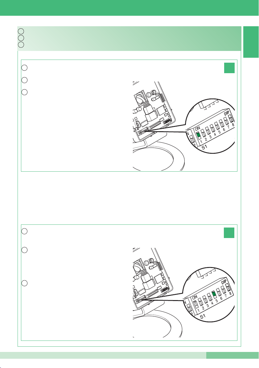
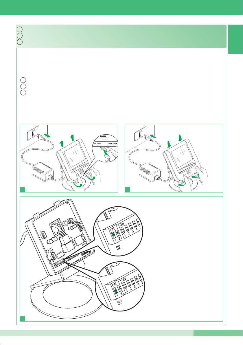
15
1
2
3
Abilitare e disabilitare il menu installatore.
La procedura é valida per tutte le staffe, monofamiliari e bifamiliari
Per abilitare Dip 1 di S2 su ON
Per disabilitare Dip 1 di S2 su OFF
To disable Dip 1 of S2 - OFF
To enable Dip 1 of S2 - ON
The procedure applies to all single-residence and two-residence brackets.
Enabling and disabling the installer menu using.
Pour invalider le Dip 1 de S2 sur OFF
Pour valider le Dip 1 de S2 sur ON
La procédure est valable pour toutes les brides, pour un appartement et deux appartements
Valider et invalider le menu d’installation.
Page 26
GROUP S.P.A.
26
MT KIT 12
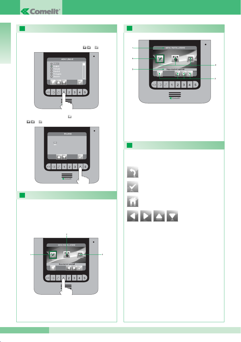
16
17
18
19
ITALIANO
IMPOSTAZIONE LINGUA MENU
Al primo accesso al menu (pulsante 1), viene richiesto
di impostare la lingua di utilizzo.
Selezionare la lingua desiderata con e
uscire dal menu premendo e confermare la scelta
con e .
ACCEDERE AL MENU INSTALLATORE
Per accedere al menu installatore premere il
pulsante 1.
1 Impostazioni speciali (vedi punti 23, 24, 26).
2 Configura pulsanti (vedi punto 22 ).
3 Configura monitor (vedi punti 20, 25, 27, 28).
DESCRIZIONE MENU INSTALLATORE
1 Titolo menu attualmente aperto.
2 Titolo menu selezionato.
3 Icone menu.
4 Cornice indicante il menu selezionato.
5 Icone funzione abbinate ai pulsanti.
Permette di aprire / confermare il
menu selezionato.
DESCRIZIONE ICONE ABBINATE AI PULSANTI
Le icone determinano la funzione svolta dal
pulsante sottostante come descritto di seguito:
Permette di arretrare di un livello o uscire dal
menu.
Permette di spostarsi all’interno del menu / aumentare
e diminuire un valore selezionato.
Permette di tornare al menu principale.
Page 27
MT KIT 12
MT KIT 12
27
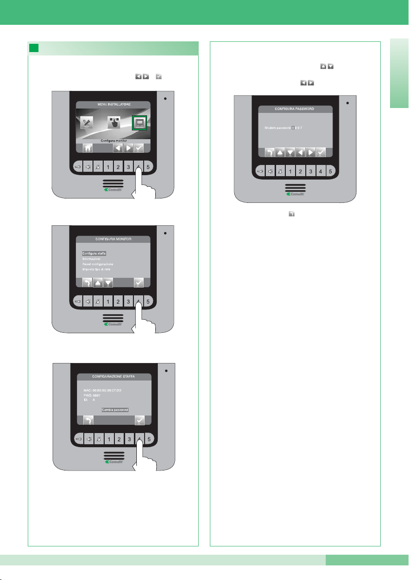
20
ITALIANO
Accedere al menu “Cambia password”.
Accedere al menu “Configura staffa”.
Dal menu installatore (pulsante 1) accedere al menu
“Configura monitor” con e .
CONFIGURAZIONE PASSWORD MODEM
Inserire la passwrod del ponte collegato all’unità
abitativa interessata (punto 14C) modificando il
numero selezionato con i pulsanti . Per passare
al numero successivo o precedente usare i
pulsanti .
Premere il pulsante per uscire e salvare le
modifiche.
Se concluse le operazioni di configurazione
disabilitare il menu installatore.
Page 28
GROUP S.P.A.
28
MT KIT 12
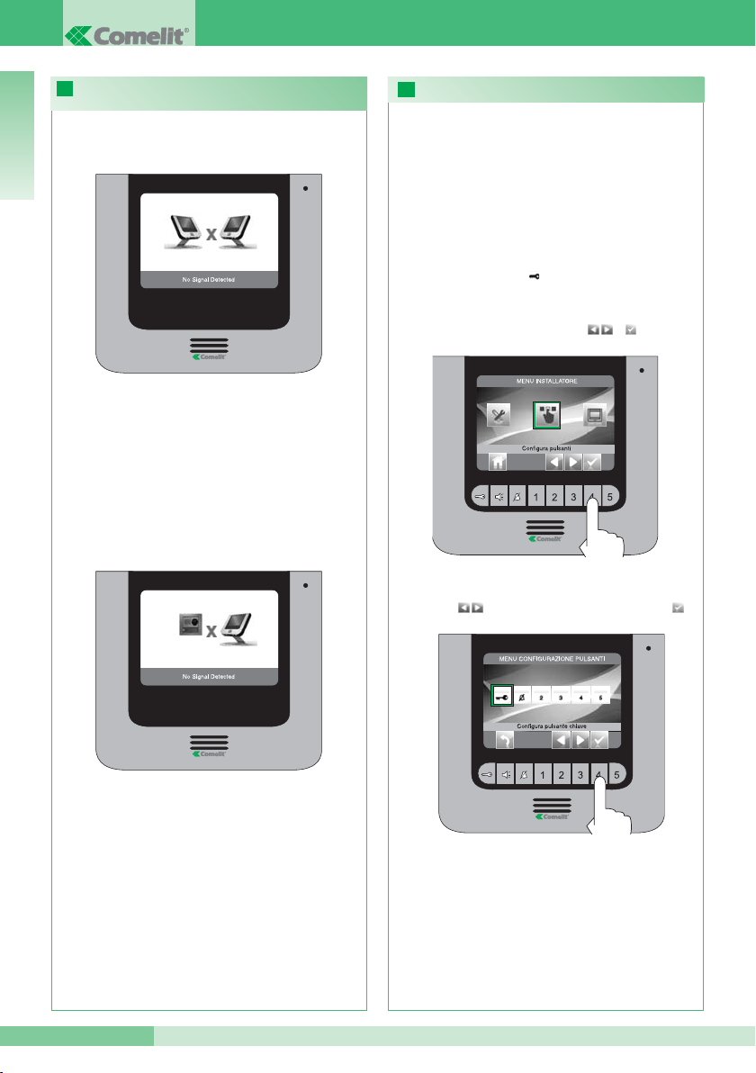
22
21
ITALIANO
Selezionare l’icona “Configura Pulsante Chiave” con
i pulsanti e confermare la scelta premendo .
Dal menu installatore (pulsante 1) accedere al menu
“Configura pulsanti” con e .
• PULSANTE CHIAVE
CONFIGURAZIONE PULSANTI
Il kit dispone di 2 relé (relé 1 e relé 2) per ogni posto
esterno connesso.
È possibile configurarne il funzionamento sia
durante che in assenza di chiamata (impianto a
riposo).
Con ogni pulsante configurato per il comando dei
relé , è possibile attivare contemporaneamente 2
relé* al massimo.
In caso di chiamata, uno dei relé attivabili è
necessariamente quello della porta chiamante.
In caso di connessione mancante con il posto
interno, attendere 1 minuto. Se la segnalazione si
ripresenta assicurarsi:
• Che il monitor secondario abbia lo stesso indirizzo del
monitor principale dell’unità abitativa interessata
(punto 14A).
• Che il monitor principale sia alimentato (punto 11).
• Che sia stata inserita la password corretta (punto 14C
e 20).
• Che siano state rispettate le distanze di installazione
(punto 8).
SEGNALAZIONE ANOMALIE E POSSIBILI
SOLUZIONI
In caso di connessione mancante con il posto
esterno assicurarsi:
• Che il posto esterno sia correttamente cablato
(punto 2) e che sia alimentato (punto 8).
• Che il ponte Art. 1398 sia correttamente cablato
(punto 7A, 7B, 7C).
• Che ci sia corrispondenza tra la password del
ponte Art. 1398 e l’alimentatore monitor della
stessa unità abitativa.
• Che siano rispettate le distanze di installazione
(punto 8).
* In caso di attivazione contemporanea di 2 relé
disporre per uno dei carichi un alimentatore
dedicato.
Page 29
MT KIT 12
MT KIT 12
29
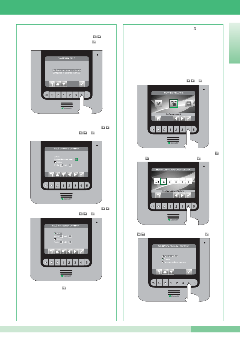
Premere il pulsante per uscire e salvare le
modifiche.
ITALIANO
Selezionare i campi modificabili con i pulsanti e
modificare il valore con o .
Selezionare i campi modificabili con i pulsanti e
modificare il valore con o .
Selezionare la modalità per la quale si vuole
modificare la funzione con i pulsanti e
confermare la scelta premendo .
Se concluse le operazioni di configurazione
disabilitare il menu installatore.
Selezionare la funzione desiderata con i pulsanti
e confermare la scelta premendo .
Selezionare l’icona “Configura privacy /dottore” con i pulsanti
e confermare la scelta premendo .
• PULSANTE PRIVACY / DOTTORE
• La funzione Privacy permette l'esclusione della chiamata dal
posto esterno o intercomunicante.
• La funzione Dottore permette l’azionamento automatico
dell’apriporta (relé 1) su chiamata da posto esterno.
• La funzione Dottore + Privacy oltre a disattivare la suoneria del
citofono come nella funzione Privacy, permette l’azionamento
automatico dell’apriporta (relé 1) su chiamata da posto
esterno.
Se concluse le operazioni di configurazione
disabilitare il menu installatore.
Dal menu installatore (pulsante 1) accedere al menu
“Configura pulsanti” con e .
Page 30
GROUP S.P.A.
30
MT KIT 12
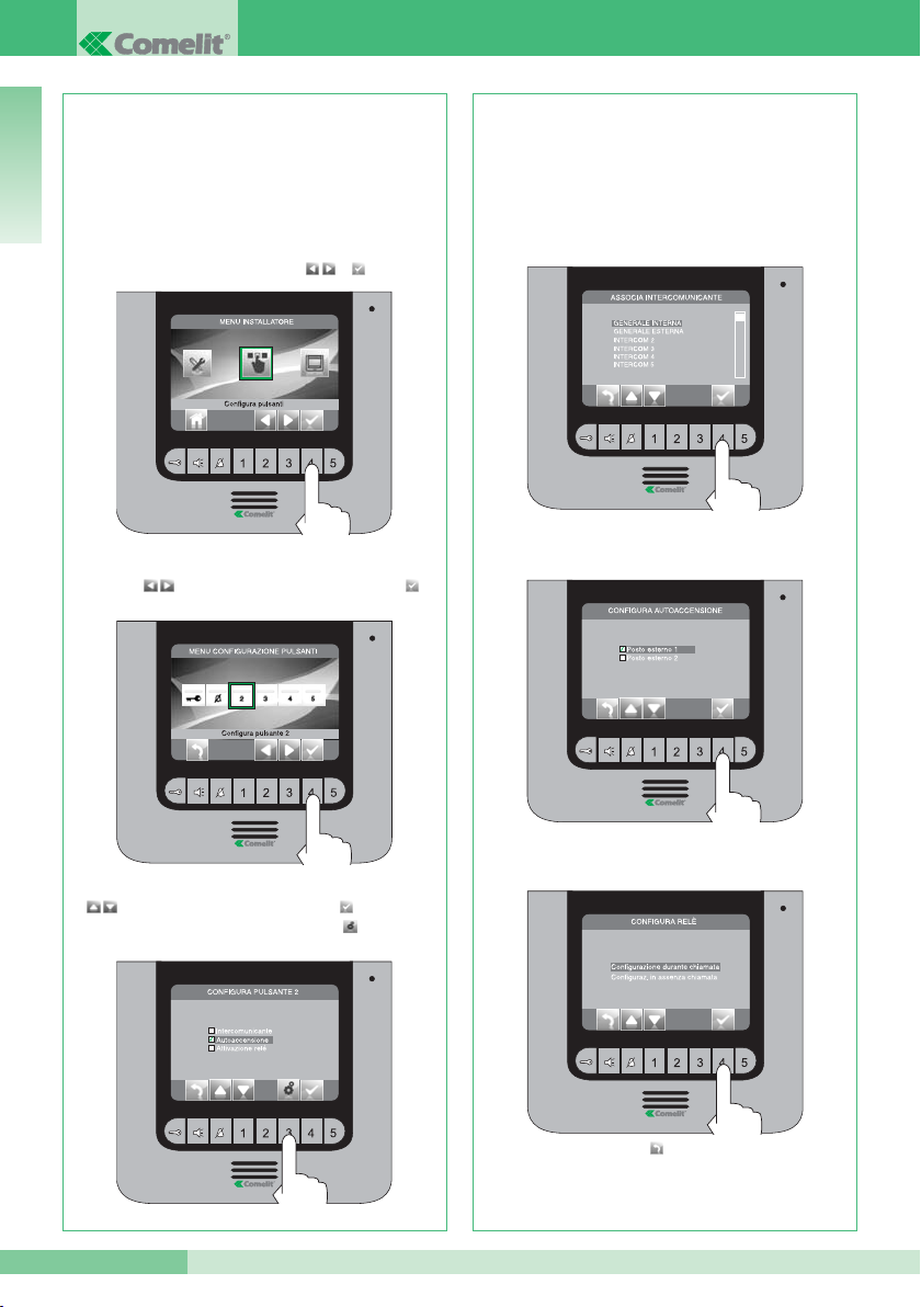
Se è stata selezionata la funzione
“Intercomunicante” nel passo precedente, occorre
associare il pulsante ad un posto interno.
INTERCOM X (vedi punto 14 B).
Se è stata selezionata la funzione “Autoaccensione”
nel passo precedente, occorre associare il pulsante
ad uno o entrambi i posti esterni
Se è stata selezionata la funzione “Attivazione relé”
nel passo precedente, seguire la procedura indicata
per la programmazione del Pulsante chiave
Se concluse le operazioni di configurazione
disabilitare il menu installatore.
Selezionare la funzione desiderata con i pulsanti
, confermare la scelta premendo e premere
successivamente il pulsante .
Selezionare l’icona “Configura Pulsante 2” con i
pulsanti e confermare la scelta premendo .
I pulsanti 2, 3, 4 e 5 possono essere programmati
tutti con lo stesso procedimento. Di seguito viene
illustrata la programmazione del pulsante 2.
• PULSANTI 2 - 3 - 4 - 5
GENERALE INTERNA: Invia una chiamata a tutti i
monitor della stessa unità abitativa.
GENERALE ESTERNA: Invia una chiamata a tutti i
monitor dell’altra unità abitativa.
Dal menu installatore (pulsante 1) accedere al menu
“Configura pulsanti” con e .
Premere il pulsante per uscire e salvare le
modifiche.
ITALIANO
Page 31
MT KIT 12
MT KIT 12
31
23 24
Premere il pulsante per uscire e salvare le
modifiche.
Premere il pulsante per uscire e salvare le
modifiche.
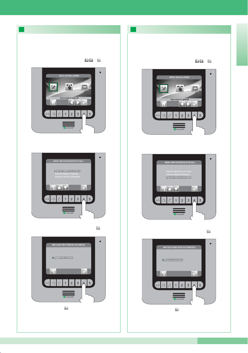
ATTIVAZIONE RIPETIZIONE SUONERIA
Confermare la scelta premendo
Accedere al menu “Imposta ripetizione suoneria”
Dal menu installatore (pulsante 1) accedere a
“Impostazioni speciali” con e .
Con questa funzione attivata il monitor ripeterà la
suoneria tre volte dopo la ricezione di una chiamata
Se concluse le operazioni di configurazione
disabilitare il menu installatore.
ATTIVAZIONE RISPOSTA AUTOMATICA
Confermare la scelta premendo
Accedere al menu “Imposta risposta automatica”
Dal menu installatore (pulsante 1) accedere al menu
“Impostazioni speciali” con e .
Con questa funzione impostata, la fonica viene
automaticamente attivata dopo la ricezione di una
chiamata
Se concluse le operazioni di configurazione
disabilitare il menu installatore.
ITALIANO
Page 32
GROUP S.P.A.
32
MT KIT 12
26
Reset configurazione
25
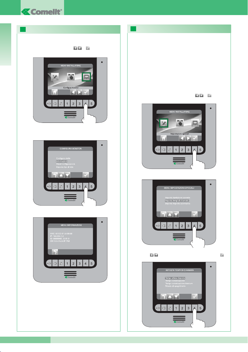
CONFIGURAZIONE TEMPI DI CHIAMATA
Selezionare il valore che si vuole modificare con i
pulsanti e confermare la scelta premendo .
Accedere al menu “Imposta tempi di chiamata”
All’interno di questo menu è possibile modificare:
• Tempo attesa risposta: tempo massimo oltre il quale la
comunicazione termina in assenza di risposta
• Tempo conversazione: durata di una conversazione tra posto
interno e posto esterno.
• Tempo conversazione intercom: durata di una conversazione
intercomunicante.
• Ritardo di spegnimento: dopo una chiamata, tempo di attesa
dall’attivazione di un relé allo spegnimento del monitor.
Dal menu installatore (pulsante 1) accedere a
“Impostazioni speciali” con e .
VISUALIZZA INFORMAZIONI
Accedere al menu “Informazioni”
Dal menu installatore accedere al menu “Impostazioni
speciali” con e .
Se concluse le operazioni di configurazione
disabilitare il menu installatore.
ITALIANO
Page 33
MT KIT 12
MT KIT 12
33
27
28
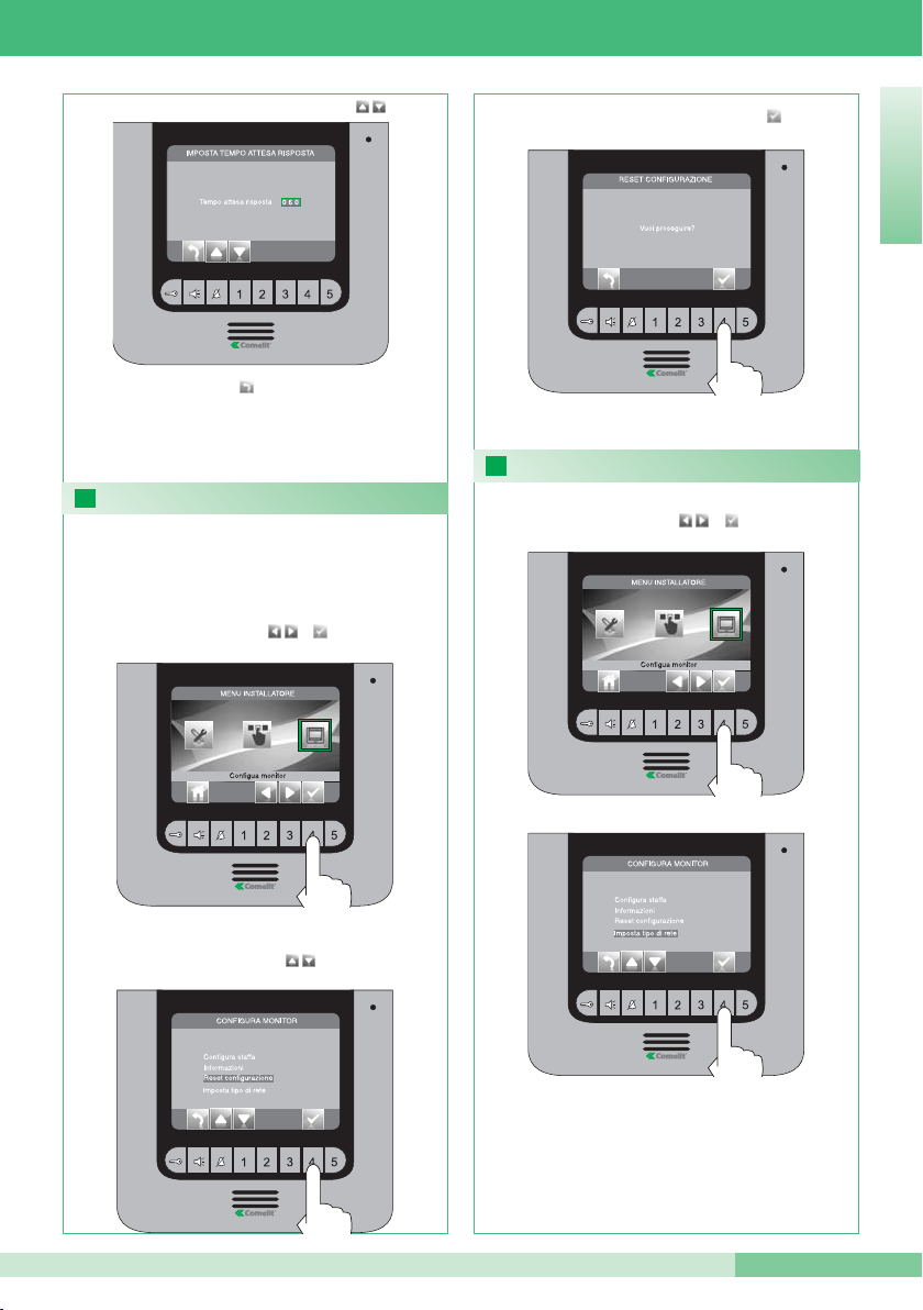
RESET CONFIGURAZIONE
Dal menu installatore accedere al menu “Configura
monitor” con e .
Questa operazione ripristinerà tutte le
impostazioni di fabbrica, annullando tutte le
modifiche apportate
Selezionare il menu “reset configurazione”
con i pulsanti .
Confermare la scelta premendo .
Modificare il valore con i pulsanti
Se concluse le operazioni di configurazione
disabilitare il menu installatore.
MENU IMPOSTA TIPO DI RETE
Dal menu installatore accedere al menu “Configura
monitor” con e .
NON MODIFICARE ASSOLUTAMENTE QUESTO
VALORE.
Il valore impostato di fabbrica è IPOWER.
Premere il pulsante per uscire e salvare le
modifiche.
ITALIANO
Page 34
GROUP S.P.A.
34
MT KIT 12
16
17
18
19
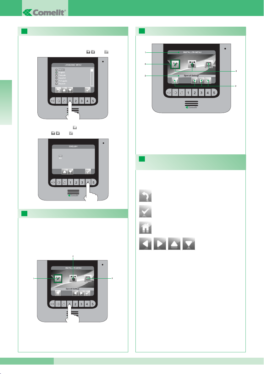
SETTING THE MENU LANGUAGE
ENTERING THE INSTALLER MENU
DESCRIPTION OF THE INSTALLER MENU
DESCRIPTION OF THE ICONS CORRESPONDING
TO THE PUSHBUTTONS
When you first enter the menu (pushbutton 1), you will
be asked to set the language.
Select the desired language using and
Exit the menu by pressing and confirm your
selection using and .
To enter the installer menu, press pushbutton 1.
1 Special settings (see paragraphs 23, 24and 26).
2 Program pushbuttons (see paragraph 22 ).
3 Program monitor (see paragraphs 20, 25, 27 and
28).
1 Name of menu currently open.
2 Name of menu selected.
3 Menu icons.
4 Frame indicating menu selection.
5 Icons corresponding to the pushbutton
functions.
Used to open / confirm the
selected menu.
The icons identify the function performed by the
pushbuttons underneath, as follows:
Used to go back one level or exit the menu.
Used to scroll through the menu / increase and
decrease a selected value.
Used to return to the main menu.
ENGLISH
Page 35
MT KIT 12
MT KIT 12
35
20
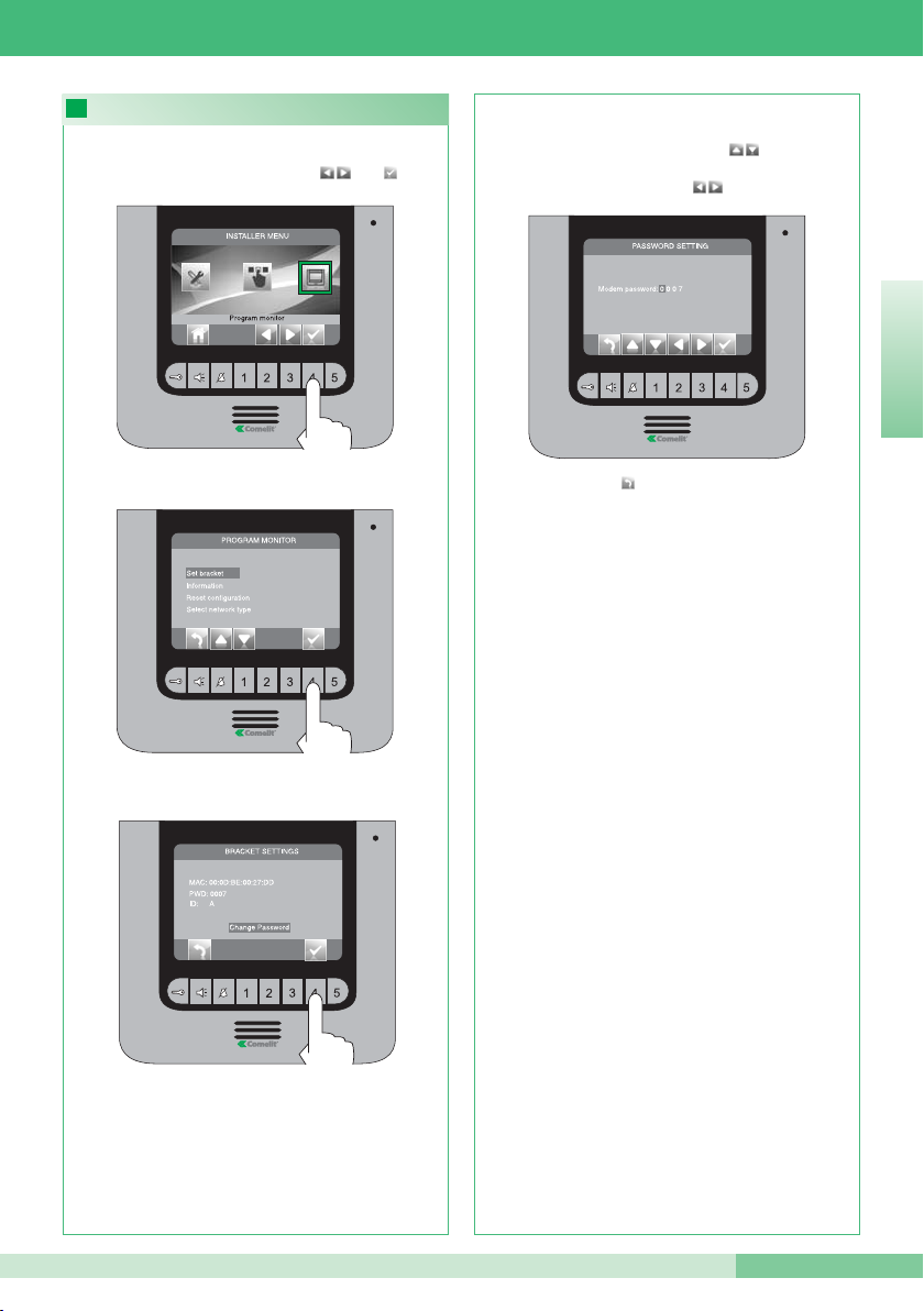
SETTING THE MODEM PASSWORD
Enter the “Change password” menu.
Enter the “Set bracket” menu.
Press pushbutton to exit and save the changes.
Once you have completed the programming
procedures, disable the installer menu.
Enter the password for the bridge connected to the
relevant residential unit (paragraph 14C), adjusting the
number selected using pushbuttons . To move on
to the following number or the previous number, use
pushbuttons .
From the installer menu (pushbutton 1), enter the
“Program monitor” menu using and .
ENGLISH
Page 36
GROUP S.P.A.
36
MT KIT 12
22
21
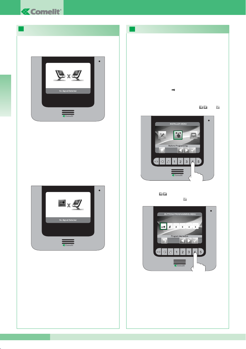
PROGRAMMING THE PUSHBUTTONS
FAULT INDICATION AND TROUBLESHOOTING
Select the “Program key button” icon using
pushbuttons and confirm your selection by
pressing .
From the installer menu (pushbutton 1), enter the
“Buttons programming” menu using and .
• KEY PUSHBUTTON
The kit has 2 relays (relay 1 and relay 2) for each
external unit connected.
Their operation may be programmed either during a
call or when the system is in standby.
When every pushbutton has been programmed for
relay control, a maximum of 2 relays* may be
activated at the same time.
In the event of a call, one of the relays activated
must correspond to the door from which the call is
made.
If there is no connection with the internal unit, wait for
1 minute. If the indication appears again, make sure:
• That the secondary monitor has the same address as
the main monitor for the relevant residential unit
(paragraph 14A).
• That the main monitor is receiving power (paragraph
11).
• That the correct password has been entered
(paragraph 14C and 20).
• That the installation distances have been observed
(paragraph 8).
If there is no connection with the external unit, make
sure:
• That the external unit is wired correctly (paragraph 2)
and that it is receiving power (paragraph 8).
• That the bridge Art. 1398 is wired correctly
(paragraph 7A, 7B, 7C).
• That the password for bridge Art. 1398 is the same
as the password for the power supply of the monitor
in the same residential unit.
• That the installation distances have been observed
(paragraph 8).
* If 2 relays are activated at the same time, provide
a special power supply for one of the loads.
ENGLISH
Page 37
MT KIT 12
MT KIT 12
37
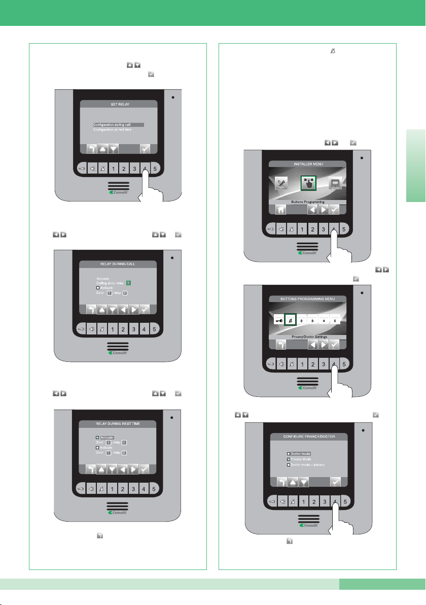
Select the fields you wish to modify using pushbuttons
and adjust the values using or .
Select the fields you wish to modify using pushbuttons
and adjust the values using or .
Select the mode for which you wish to modify the
function using pushbuttons and confirm your
selection by pressing .
Once you have completed the programming
procedures, disable the installer menu.
Select the desired function using pushbuttons
and confirm your selection by pressing .
Select the “Privacy/Doctor settings” icon using pushbuttons
and confirm your selection by pressing .
From the installer menu (pushbutton 1), enter the “Buttons
programming” menu using and .
• PRIVACY / DOCTOR BUTTON
• The Privacy mode disables calls from the external unit or
intercom.
• The Doctor mode enables automatic activation of the door-release
function (relay 1) in response to a call from the external unit.
• The Doctor + Privacy mode, as well as disabling the intercom
ringtone melody in the same way as the Privacy mode, also
enables automatic activation of the door-release function (relay 1)
in response to a call from the external unit.
Once you have completed the programming
procedures, disable the installer menu.
Press pushbutton to exit and save the changes.
Press pushbutton to exit and save the changes.
ENGLISH
Page 38
GROUP S.P.A.
38
MT KIT 12
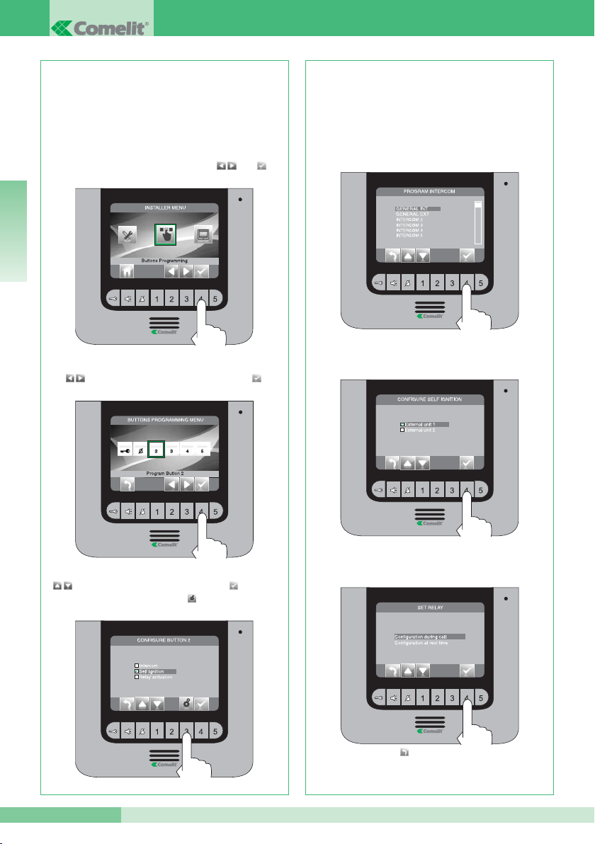
If the “Intercom” function was selected in the
previous step, the pushbutton must be assigned to
an internal unit.
INTERCOM X (see paragraph 14 B).
If the “Self-ignition” function was selected in the
previous step, the pushbutton must be assigned to
one or both of the internal units.
If the “Relay activation” function was selected in the
previous step, follow the procedure described for
Key pushbutton programming.
Once you have completed the programming
procedures, disable the installer menu.
Select the desired function using pushbuttons
, confirm your selection by pressing and then
press button .
Select the “Program Button 2” icon using pushbuttons
and confirm your selection by pressing .
From the installer menu (pushbutton 1), enter the
“Buttons programming” menu using and .
Pushbuttons 2, 3, 4 and 5 may be all programmed
using the same procedure. The programming
procedure for pushbutton 2 is illustrated below.
• PUSHBUTTONS 2 - 3 - 4 - 5
GENERAL INTERNAL: Make a call to all monitors in
the same residential unit.
GENERAL EXTERNAL: Make a call to all monitors
in the other residential unit.
Press pushbutton to exit and save the changes.
ENGLISH
Page 39
MT KIT 12
MT KIT 12
39
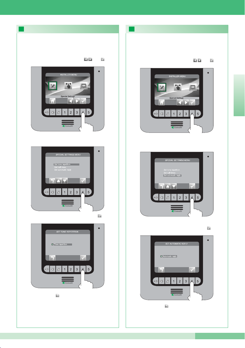
23 24
ACTIVATING RINGTONE REPETITION
ACTIVATING THE AUTOMATIC RESPONSE
Confirm your selection by pressing
Enter the “Set tone repetition” menu.
From the installer menu (pushbutton 1), enter the
“Special settings” menu using and .
When this function is active, the monitor will repeat
the ringtone three times after a call is received.
Once you have completed the programming
procedures, disable the installer menu.
Confirm your selection by pressing
Enter the “Set automatic reply” menu.
From the installer menu (pushbutton 1), enter the
“Special settings” menu using and .
When this function is selected, the audio line is
activated automatically after a call is received.
Once you have completed the programming
procedures, disable the installer menu.
Press pushbutton to exit and save the changes.
Press pushbutton to exit and save the changes.
ENGLISH
Page 40
GROUP S.P.A.
40
MT KIT 12
26
25
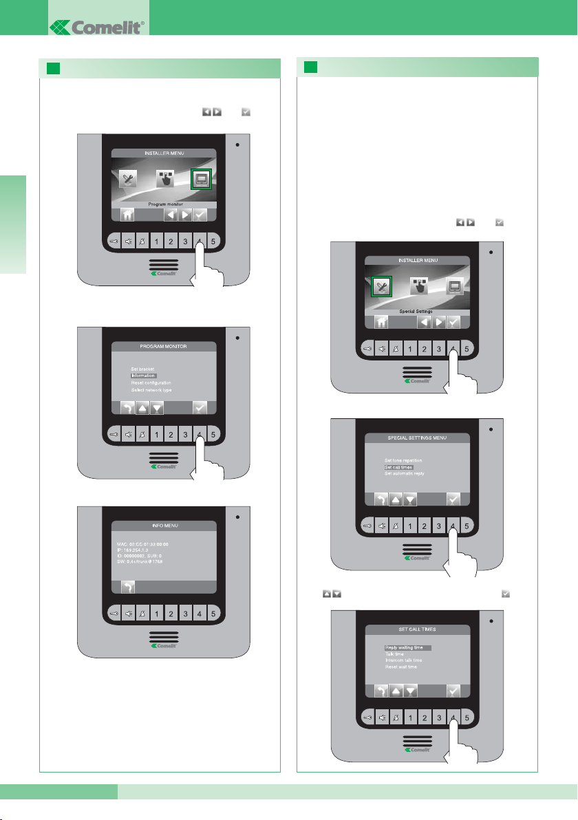
PROGRAMMING CALL TIMES
DISPLAYING INFORMATION
Select the value you wish to modify using pushbuttons
and confirm your selection by pressing .
Enter the “Set call times” menu.
This menu can be used to modify:
• Awaiting response time: maximum time beyond which
communication will be terminated if there is no response.
• Talk time: duration of a conversation between an internal unit
and the porter module.
• Intercom talk time: duration of an intercom conversation.
• Shut-down delay: after a call, the amount of time before a relay
is activated to shut down the monitor.
From the installer menu (pushbutton 1), enter the
“Special settings” menu using and .
Enter the “Information” menu.
From the installer menu (pushbutton 1), enter the
“Special settings” menu using and .
Once you have completed the programming
procedures, disable the installer menu.
ENGLISH
Page 41
MT KIT 12
MT KIT 12
41
27
28
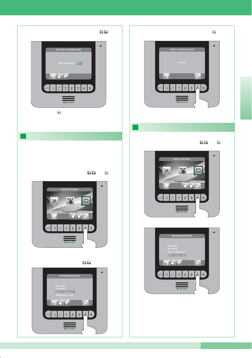
RESET CONFIGURATION
SELECT TYPE OF NETWORK MENU
From the installer menu (pushbutton 1), enter the
“Program monitor” menu using and .
This procedure will restore all default settings,
deleting all modifications made previously.
Select the “Reset configuration” menu
using pushbuttons .
Confirm your selection by pressing .
Modify the value using pushbuttons.
Once you have completed the programming
procedures, disable the installer menu.
From the installer menu (pushbutton 1), enter the
“Program monitor” menu using and .
DO NOT UNDER ANY CIRCUMSTANCES MODIFY
THIS VALUE.
The default value is IPOWER.
Press pushbutton to exit and save the changes.
ENGLISH
Page 42
GROUP S.P.A.
42
MT KIT 12
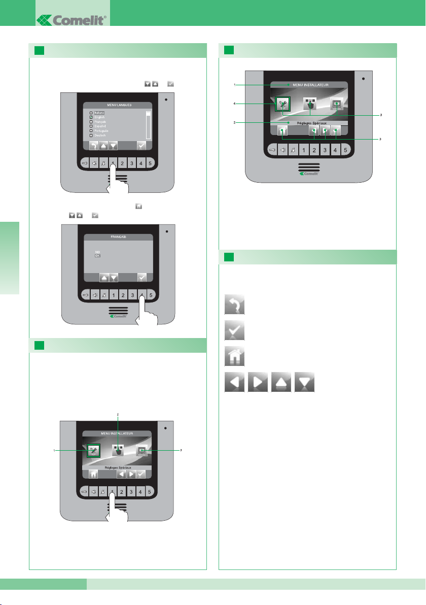
16
17
18
19
RÉGLAGE LANGUE MENU
ACCÉDER AU MENU D’INSTALLATION
DESCRIPTION MENU D’INSTALLATION
DESCRIPTION ICÔNES ASSOCIÉES AUX TOUCHES
Au premier accès au menu (touche 1), choisir la
langue que l’on désire utiliser.
Sélectionner la langue désirée avec et
quitter le menu en appuyant sur et confirmer le
choix avec et .
Pour accéder au menu d’installation, appuyer sur le
touche 1.
1 Réglages spéciaux (voir points 23, 24, 26).
2 Configuration touches (voir point 22 ).
3 Configuration moniteur (voir points 20, 25, 27, 28).
1 Titre menu actuellement ouvert.
2 Titre menu sélectionné.
3 Icônes menu.
4 Cadre indiquant le menu sélectionné.
5 Icônes fonction associées aux touches.
Permet d’ouvrir / confirmer le
menu sélectionné.
Les icônes déterminent la fonction exercée par le
touche situé dessous comme décrit ci-après :
Permet de reculer d’un niveau ou de quitter
le menu.
Permet de se déplacer à l’intérieur du menu /
d’augmenter et de diminuer une valeur sélectionnée.
Permet de retourner au menu principal.
FRANÇAIS
Page 43
MT KIT 12
MT KIT 12
43
20
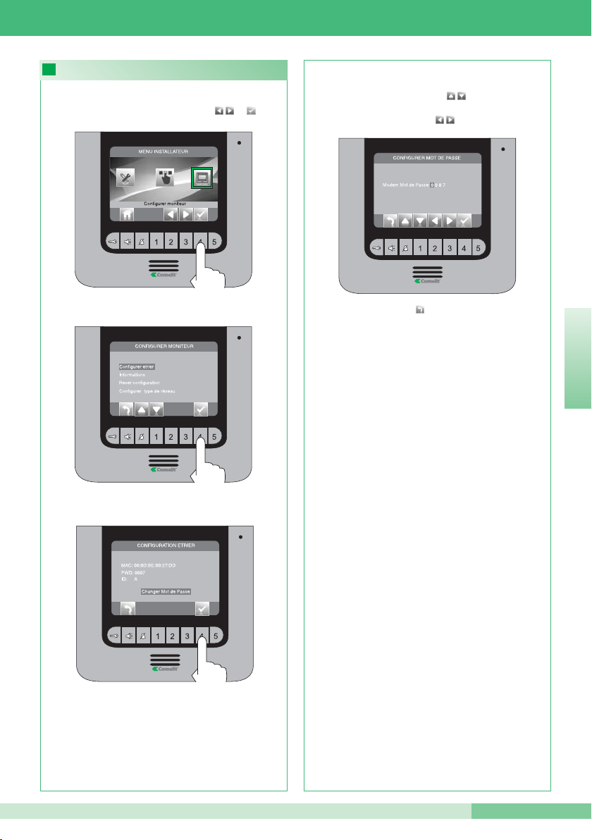
CONFIGURATION MOT DE PASSE MODEM
Accéder au menu “Changer mot de passe”.
Accéder au menu “Configurer bride”.
Depuis le menu d’installation (touche 1) accéder au
menu “Configurer moniteur” avec et .
Saisir le mot de passe du pont relié à l’habitation
concernée (point 14C) en modifiant le numéro
sélectionné avec les touches . Pour passer au
numéro suivant ou précédent, utiliser les
touches .
Appuyer sur le touche pour quitter et enregistrer
les modifications.
Lorsque les opérations de configuration sont
terminées, invalider le menu d’installation.
FRANÇAIS
Page 44
GROUP S.P.A.
44
MT KIT 12
22
21
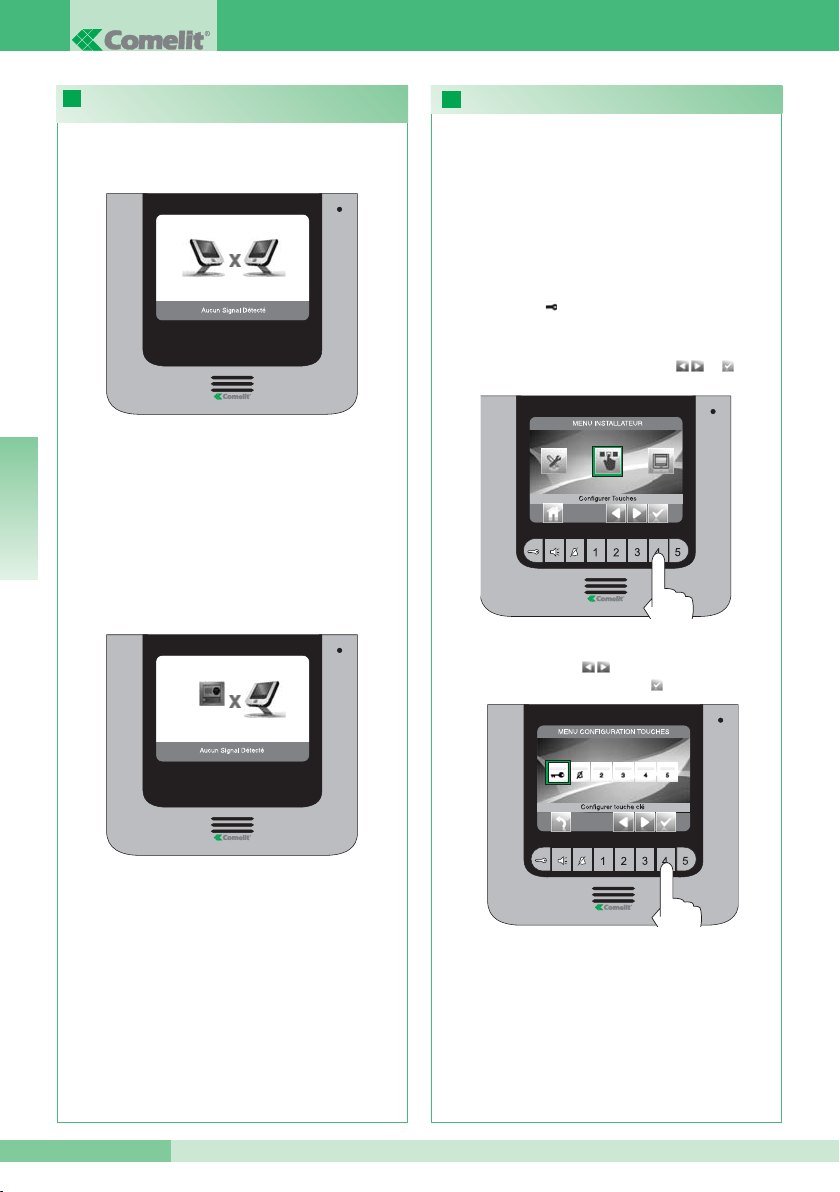
CONFIGURATION TOUCHES
SIGNALISATION ANOMALIES ET SOLUTIONS
POSSIBLES
sélectionner l’icône “Configurer Touche Clé”
avec les touches et confirmer le choix
en appuyant sur .
Depuis le menu d’installation (touche 1) accéder au
menu “Configurer touches” avec et .
• TOUCHE CLÉ
Le kit dispose de 2 relais (relais 1 et relais 2) pour
chaque plaque de rue reliée.
Il est possible d’en configurer le fonctionnement tant
durant qu’en absence d’appel (installation au repos).
Avec chaque touche configuré pour la commande
des relais, il est possible d’activer simultanément 2
relais* au maximum.
En cas d’appel, l’un des relais activable est
nécessairement celui de la porte qui appelle.
En cas de connexion non réussie avec le poste
intérieur, attendre 1 minute. Si la signalisation se
présente à nouveau, vérifier :
• que le moniteur secondaire a la même adresse que le
moniteur principal de l’habitation concernée (point
14A).
• que le moniteur principal est alimenté (point 11).
• que le mot de passe correct a été saisi (point 14C et
20).
• que les distances d’installation ont été respectées
(point 8).
En cas de connexion absente avec la plaque de rue,
vérifier :
• que la plaque de rue est correctement câblée
(point 2) et qu’elle est alimentée (point 8).
• que le pont Art. 1398 est correctement câblé (point
7A, 7B, 7C).
• qu’il y a correspondance entre le mot de passe du
pont Art. 1398 et l’alimentateur moniteur de la
même habitation.
• que les distances d’installation ont été respectées
(point 8).
* En cas d’activation simultanée de 2 relais,
disposer pour une des charges un alimenteur dédié.
FRANÇAIS
Page 45
MT KIT 12
MT KIT 12
45
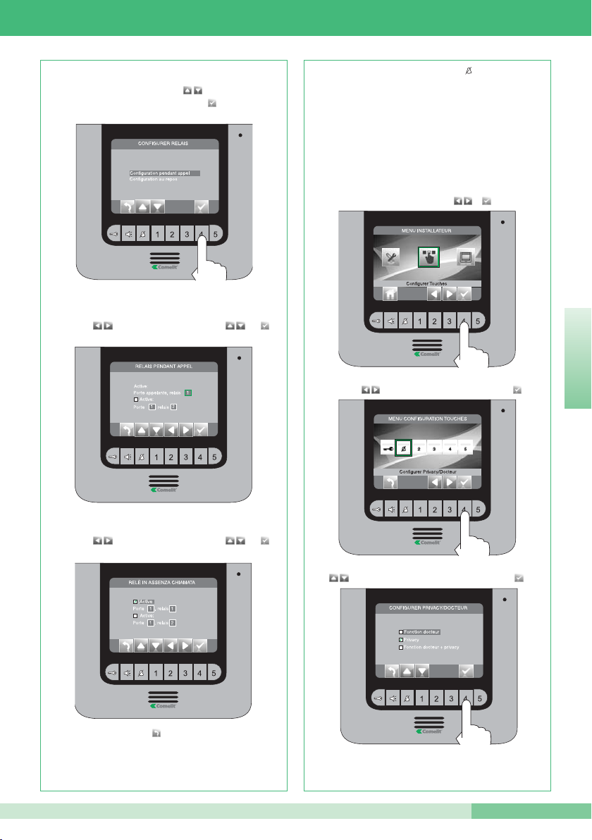
Sélectionner les champs modifiables avec les
touches et modifier la valeur avec ou .
Sélectionner les champs modifiables avec les
touches et modifier la valeur avec ou .
Sélectionner le mode pour lequel on désire modifier
la fonction avec les touches et confirmer le
choix en appuyant sur .
Lorsque les opérations de configuration sont
terminées, invalider le menu d’installation.
Sélectionner la fonction désirée avec les touches
et confirmer le choix en appuyant sur .
Sélectionner l’icône “Configurer privacy /docteur” avec les
touches et confirmer le choix en appuyant sur .
Depuis le menu d’installation (touche 1), accéder au menu
“Configurer touches” avec et .
• TOUCHE PRIVACY / DOCTEUR
• La fonction Privacy permet d’exclure l’appel depuis la plaque
de rue ou poste intercommunicant.
• La fonction Docteur permet l’activation automatique de l’ouvre
porte (relais 1) sur appel depuis plaque de rue.
• La fonction Docteur + Privacy non seulement permet de
désactiver la sonnerie de l’interphone comme dans la fonction
Privacy, mais en plus elle permet l’actionnement automatique
de l’ouvre porte (relais 1) sur appel depuis plaque de rue.
Lorsque les opérations de configuration sont
terminées, invalider le menu d’installation.
Appuyer sur le touche pour quitter et enregistrer
les modifications.
FRANÇAIS
Page 46
GROUP S.P.A.
46
MT KIT 12
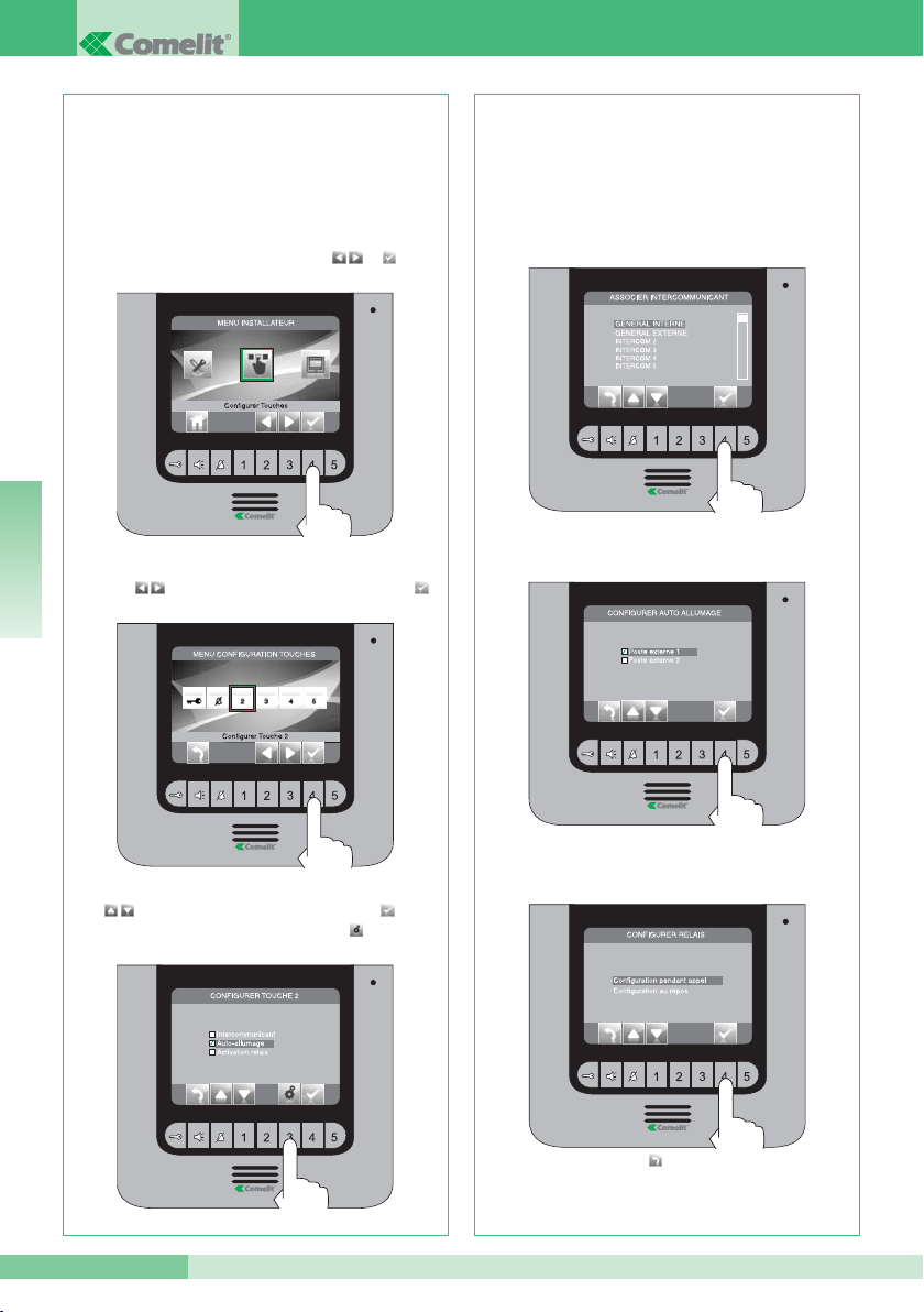
Si la fonction “Intercomunicant” a été sélectionnée
dans le passage précédent, associer le touche à un
poste intérieur.
INTERCOM X (voit point 14 B).
Si la fonction “Auto-allumage” a été sélectionnée
dans le passage précédent, il faut associer le
touche à une ou aux deux plaques de rue.
Si la fonction “Activation relais” a été sélectionnée
dans le passage précédent, suivre la procédure
indiquée pour la programmation du Touche clé
Lorsque les opérations de configuration sont
terminées, invalider le menu d’installation.
Sélectionner la fonction désirée avec les touches
, confirmer le choix en appuyant sur et
appuyer ensuite sur le touche .
Sélectionner l’icône “Configurer Touche2” avec les
touches et confirmer le choix en appuyant sur .
Depuis le menu d’installation (touche 1), accéder au
menu “Configurer touches” avec et .
Les touches 2, 3, 4 et 5 peuvent être tous
programmés avec la même procédure. Ci-dessous,
illustration de la programation du touche 2.
• TOUCHES 2 - 3 - 4 - 5
GÉNÉRAL INTERNE : envoie un appel à tous les
moniteurs de la même habitation.
GÉNÉRAL EXTERNE : envoie un appel à tous les
moniteurs de l’autre habitation.
Appuyer sur le touche pour quitter et enregistrer
les modifications.
FRANÇAIS
Page 47
MT KIT 12
MT KIT 12
47
23 24
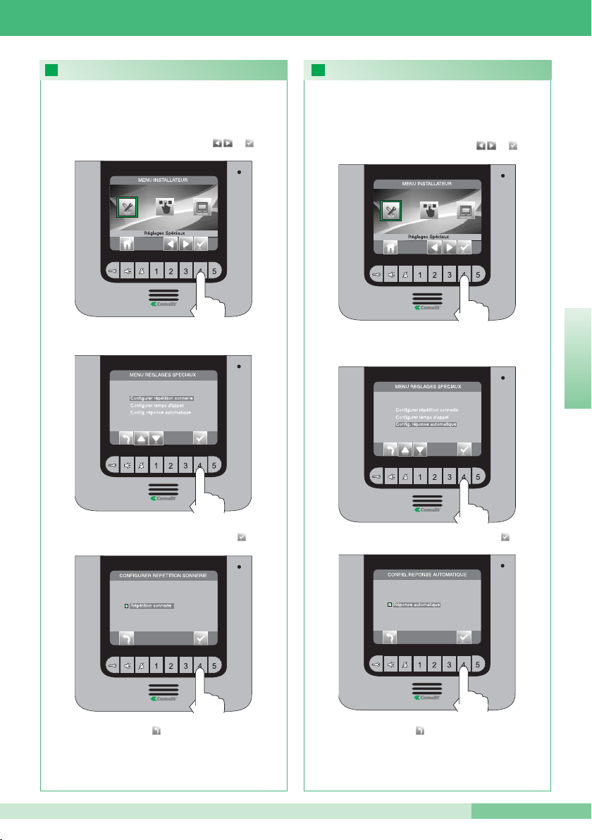
ACTIVATION RÉPÉTITION SONNERIE
ACTIVATION RÉPONSE AUTOMATIQUE
Confirmer le choix en appuyant sur
Accéder au menu “Configurer répétition sonnerie”
Depuis le menu d’installation (touche 1), accéder au
menu “Réglages spéciaux” avec et .
Avec cette fonction active, le moniteur répètera la
sonnerie trois fois après la réception d’un appel
Lorsque les opérations de configuration sont
terminées, invalider le menu d’installation.
Confirmer le choix en appuyant sur
Accéder au menu “Réponse automatique”
Depuis le menu d’installation (touche 1), accéder au
menu “Réglages spéciaux” avec et .
Avec cette fonction programmée, la fonction
phonique est automatiquement activée après la
réception d’un appel
Lorsque les opérations de configuration sont
terminées, invalider le menu d’installation.
Appuyer sur le touche pour quitter et enregistrer
les modifications.
Appuyer sur le touche pour quitter et enregistrer
les modifications.
FRANÇAIS
Page 48
GROUP S.P.A.
48
MT KIT 12
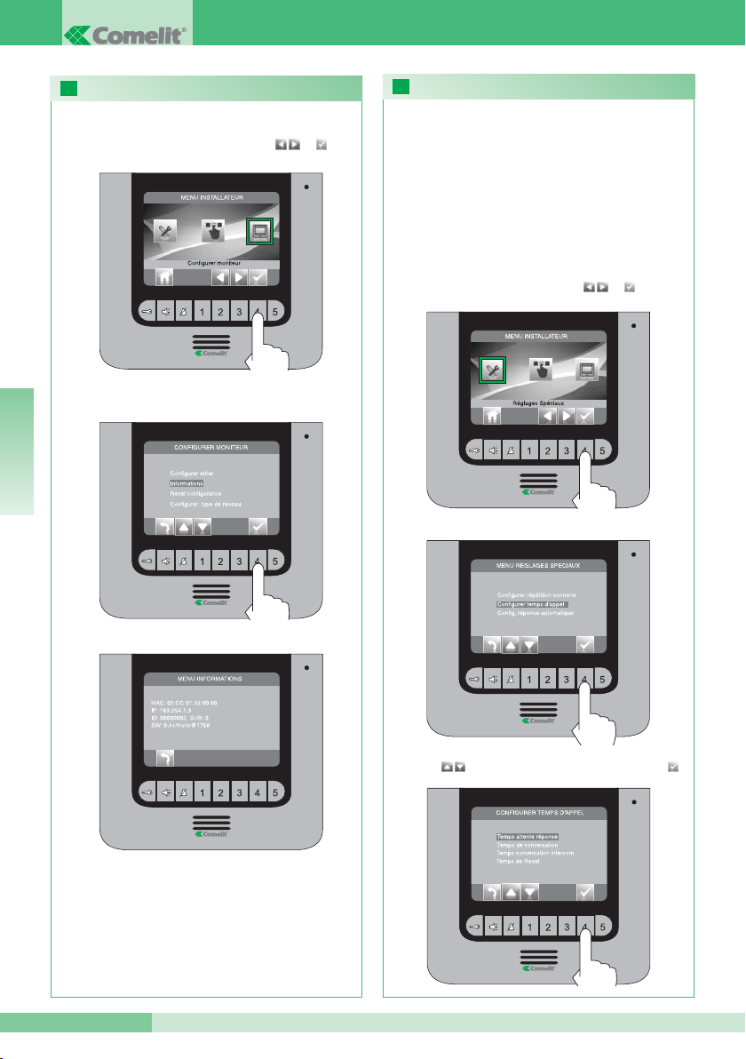
Accéder au menu “Configurer temps d’appel”
26
25
CONFIGURATION TEMPS D’APPEL
VISUALISER INFORMATIONS
Sélectionner la valeur que l’on veut modifier avec les
touches et confirmer le choix en appuyant sur .
Dans ce menu, il est possible de modifier :
• Temps d’attente réponse : temps maximum au-delà duquel la
communication se termine en absence de réponse
• Temps conversation : durée d’une conversation entre poste
intérieur et plaque de rue
• Temps conversation intercom : durée d’une conversation
intercommunicante
• Retard d’extinction : après un appel, temps d’attente depuis
l’activation d’un relais jusqu’à l’extinction du moniteur.
Depuis le menu d’installation (touche 1), accéder au
“Réglages spéciaux” avec et .
Accéder au menu “Informations”
Depuis le menu d’installation (touche 1), accéder au
menu “Configurer moniteur” avec et .
Lorsque les opérations de configuration sont
terminées, invalider le menu d’installation.
FRANÇAIS
Page 49
MT KIT 12
MT KIT 12
49
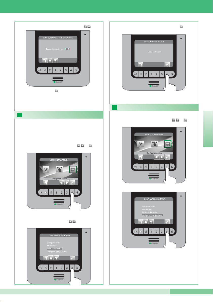
Depuis le menu d’installation (touche 1), accéder au
menu “Configurer moniteur” avec et .
27
28
MENU PROGRAMMATION TYPE DE RÉSEAU
Depuis le menu d’installation (touche 1), accéder au
menu “Configurer moniteur” avec et .
Cette opération rétablira tous les réglages
d’usine, en annulant toutes les modifications
apportées
Sélectionner le menu “reset configuration”
avec les touches .
Confirmer le choix en appuyant sur .
Modifier la valeur avec les touches
Lorsque les opérations de configuration sont
terminées, invalider le menu d’installation.
NE MODIFIER EN AUCUN CAS CETTE VALEUR.
La valeur programmée par défaut est IPOWER.
RESET CONFIGURATION
Appuyer sur le touche pour quitter et enregistrer
les modifications.
FRANÇAIS
Page 50
GROUP S.P.A.
50
MT KIT 12
IT
EN
FR
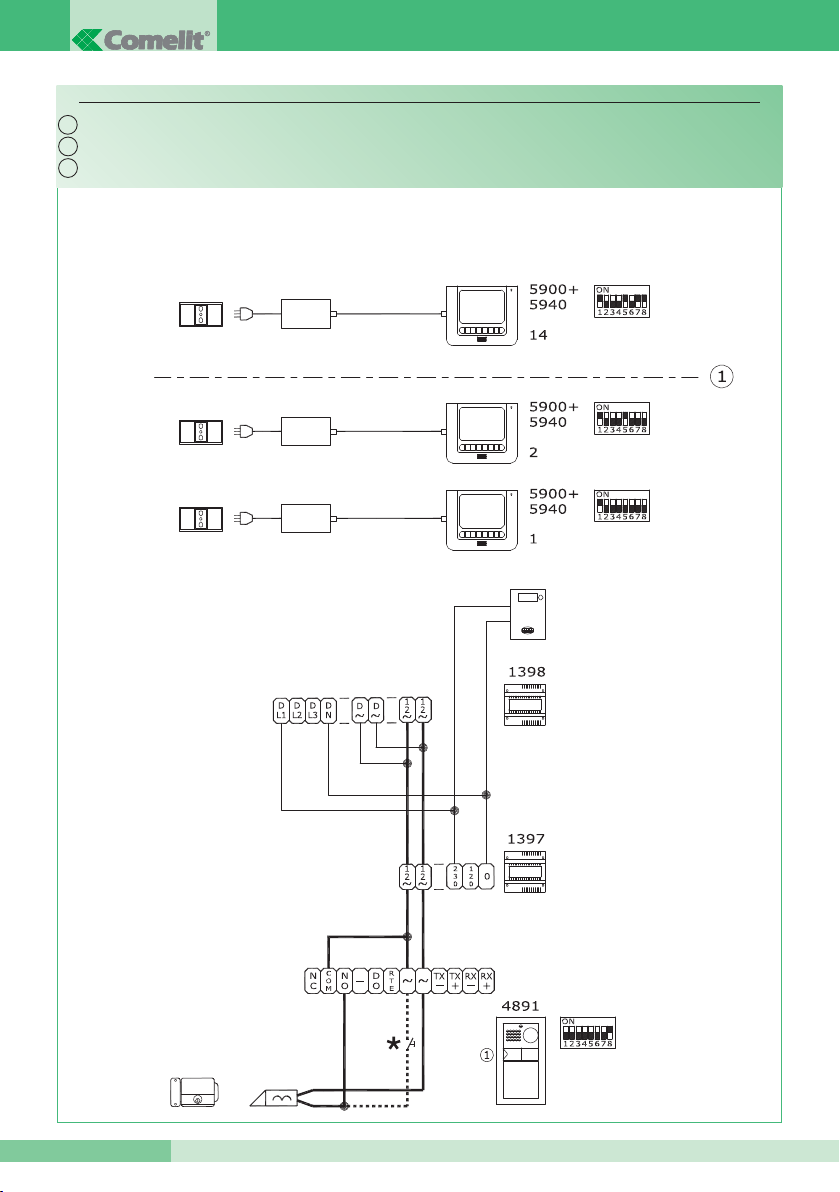
PWK/01A
Cablaggio kit monofamiliare Art. 8591.
Contatore
* Pulsante comando apriporta locale
Meter
Wiring for single-residence kit Art. 8591.
* Door-release pushbutton
Compteur
* Touche commande ouvre-porte local
Câblage kit un appartement Art. 8591.
Page 51
MT KIT 12
MT KIT 12
51
IT
EN
FR
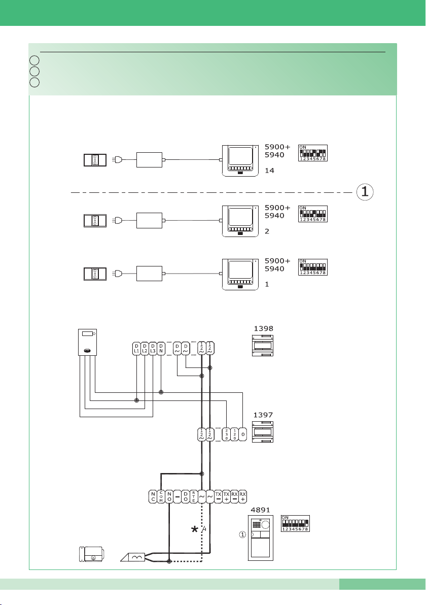
PWK/05
Cablaggio kit monofamiliare trifase Art. 8591.
* Pulsante comando apriporta locale
Contatore
* Door-release pushbutton
Meter
Wiring for three-phase single-residence kit Art. 8591.
* Touche commande ouvre-porte local
Compteur
Câblage kit un appartement triphasé Art. 8591.
Page 52
GROUP S.P.A.
52
MT KIT 12
IT
EN
FR
PWK/02A
* Pulsante comando apriporta locale
Contatore
Cablaggio kit bifamiliare Art. 8592.
Meter
* Door-release pushbutton
Wiring for two-residence kit Art. 8592.
Compteur
* Touche commande ouvre-porte local
Câblage kit deux appartements Art. 8592.
Page 53
MT KIT 12
MT KIT 12
53
IT
EN
FR
PWK/06
* Pulsante comando apriporta locale
Contatore
Cablaggio kit bifamiliare trifase Art. 8592.
Meter
* Door-release pushbutton
Wiring for three-phase two-residence kit Art. 8592.
Compteur
* Touche commande ouvre-porte local
Câblage kit deux appartement triphasé Art. 8592.
Page 54
GROUP S.P.A.
54
MT KIT 12
IT
EN
FR
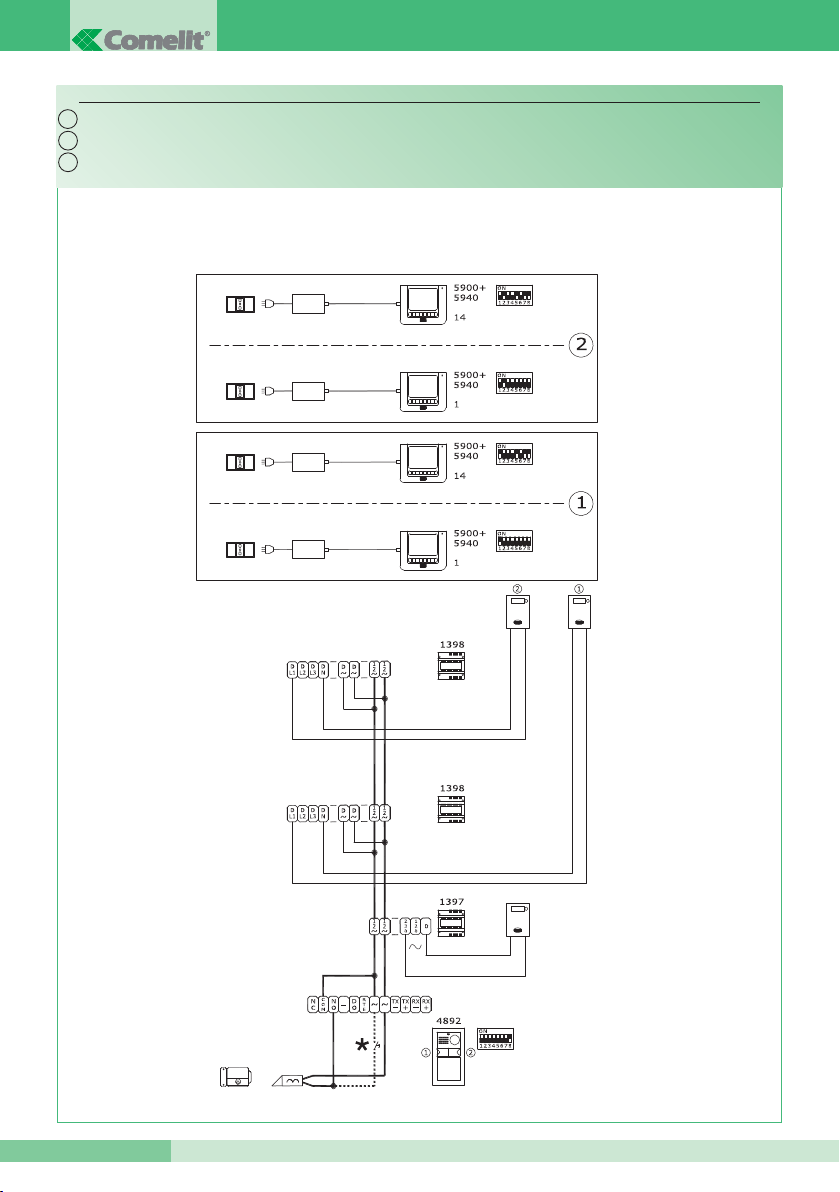
PWK/02B
* Pulsante comando apriporta locale
Contatore
Cablaggio kit bifamiliare Art. 8592 con contatore parti comuni.
* Door-release pushbutton
Meter
Wiring for two-residence kit Art. 8592 with shared parts meter.
* Touche commande ouvre-porte local
Compteur
Câblage kit deux appartements Art. 8592 ave compteur parties communes.
Page 55
MT KIT 12
MT KIT 12
55
IT
EN
FR
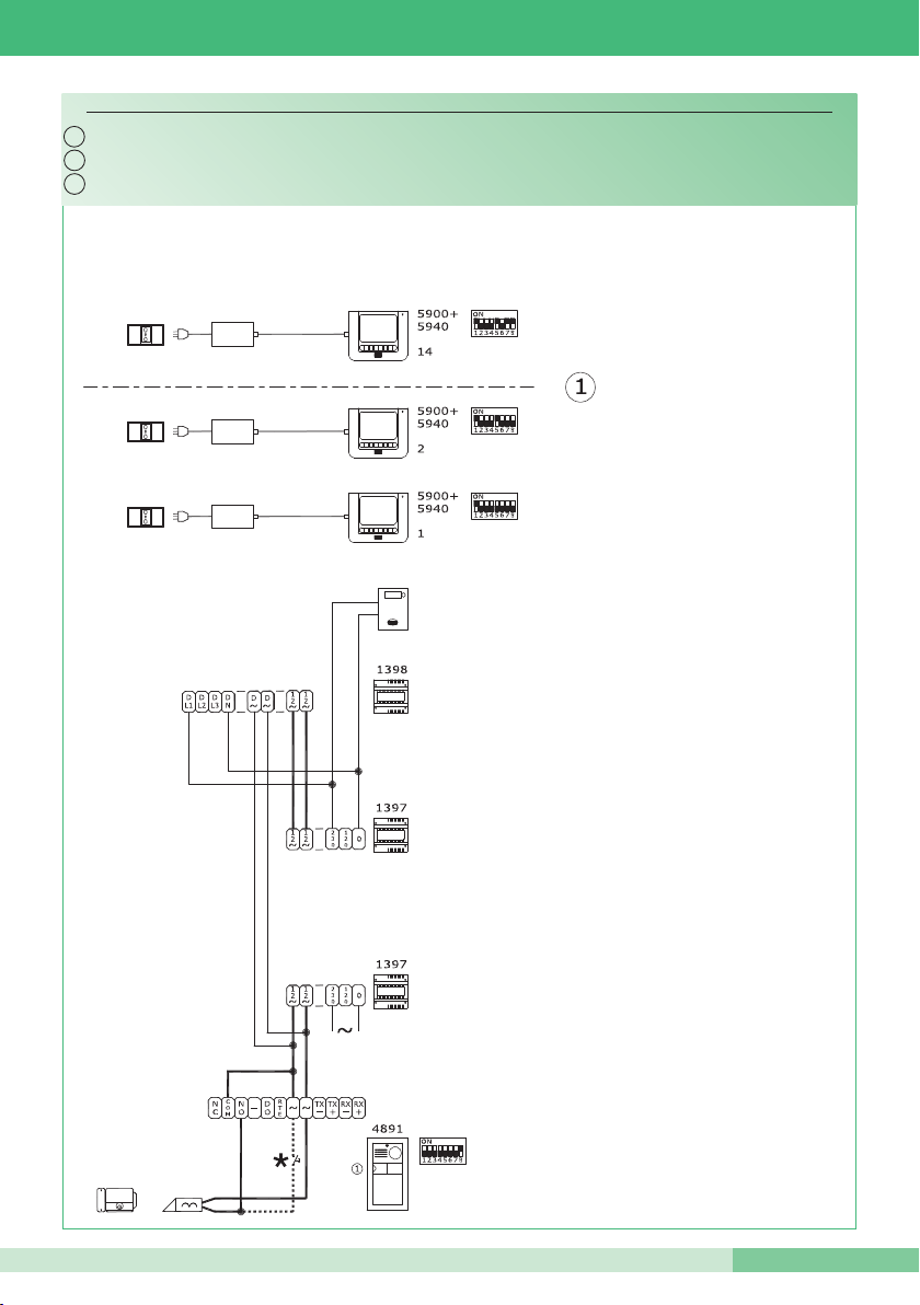
PWK/01B
Cablaggio kit monofamiliare con alimentatore supplementare per posto esterno.
* Pulsante comando apriporta locale
Contatore
Wiring for single-residence kit with additional external unit power supply.
* Door-release pushbutton
Meter
* Touche commande ouvre-porte local
Compteur
Câblage kit un appartement avec alimentateur supplémentaire pour plaque de rue.
Page 56
GROUP S.P.A.
56
MT KIT 12
IT
EN
FR
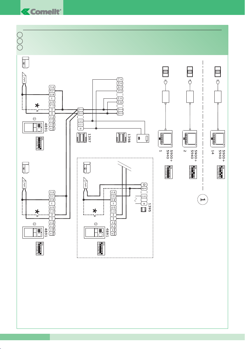
PWK/03
Cablaggio kit monofamiliare con 2 posti esterni.
* Pulsante comando apriporta locale
Serratura da alimentare a parte se attivata
contemporaneamente a quella dell’altro posto
esterno
Wiring for single-residence kit with 2 external units.
* Door-release pushbutton
Door-release device to be powered separately
if activated at the same time as the device for
the other external unit.
* Touche commande ouvre-porte local
Gâche à alimenter à part si activée
simultanément à celle de l’autre plaque de
rue
Câblage kit un appartement avec 2 plaques de rue.
Page 57
MT KIT 12
MT KIT 12
57
IT
EN
FR
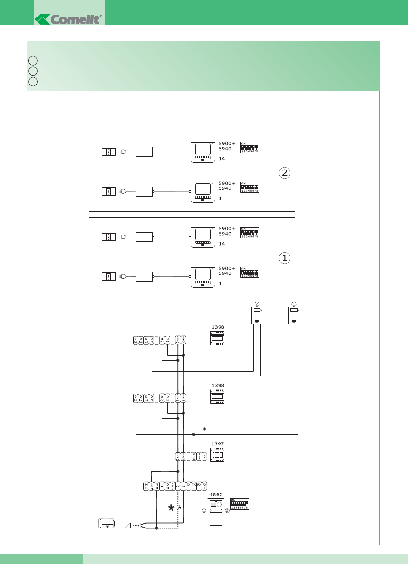
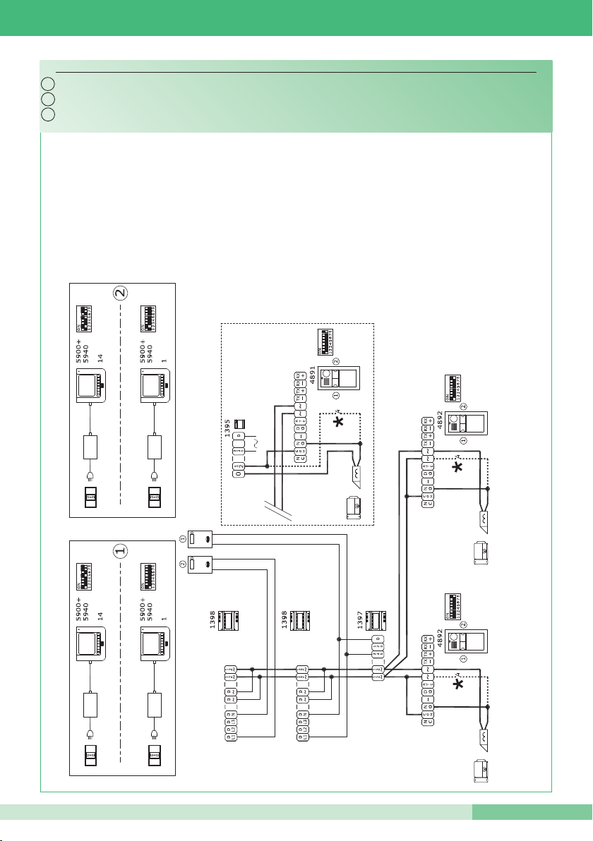
PWK/04
* Pulsante comando apriporta locale
Cablaggio kit bifamiliare con 2 posti esterni.
Serratura da alimentare a parte se
attivata contemporaneamente a quella
dell’altro posto esterno
* Door-release pushbutton
Door-release device to be powered
separately if activated at the same time
as the device for the other external unit.
Wiring fo Two-residence kit with 2 external units.
* Touche commande ouvre-porte local
Gâche à alimenter à part si activée
simultanément à celle de l’autre plaque
de rue
Câblage kit deux appartements avec 2 plaques de rue.
Page 58
GROUP S.P.A.
58
MT KIT 12
IT
EN
FR
IT
EN
FR
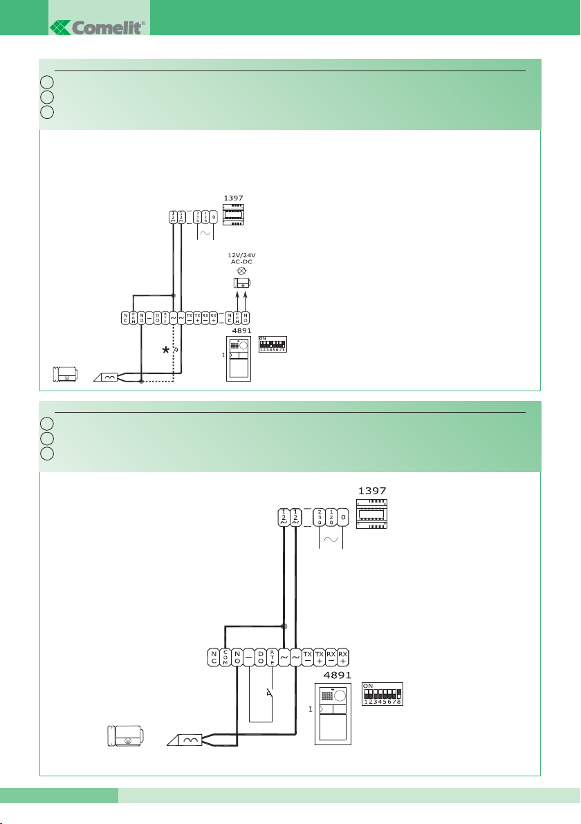
PW/AAA
PW/AAB
Variante collegamento relé temporizzato.
Variante collegamento relé del modulo numero civico (relé 2). Vedi punto 13
Utilizzare un alimentatore dedicato
* Vedi tabella programmazione posto esterno per uso
relé numero 2. Vedi punto 6
Contatto libero 12-24 V AC/DC Max 2A
Variant with timed relay connection (Request to exit).
Variant with house number module relay connection (relay 2). See paragraph 13
Use a special power supply
* See table - programming external unit for use with
relay number 2. See paragraph 6
Free contact 12-24 V AC/DC Max 2A
Variante connexion relais temporisé.
Variante connexion relais du module numéro de rue (relais 2). Voir point 13
Utiliser un alimentateur spécial
* Voir tableau programmation plaque de rue pour em-
ploi relais numéro 2. Voir point 6
Contact libre 12-24 V CA/CC Max 2A
Page 59
MT KIT 12
MT KIT 12
59
IT
EN
FR
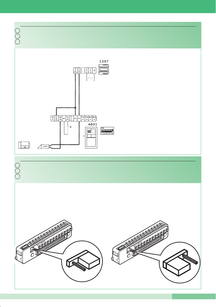
PW/AAC
IT
EN
FR
N.C. contact for DOOR OPEN signalling
Contact N.F. pour signalisation PORTE OUVERTE
Sui contatti COM. NO.
Contatto N.C. per segnalazioni PORTA APERTA
Variante per utilizzo rete RC per filtro serratura sui contatti del relé 1 o relé 2.
Variante contatto segnalazione porta aperta.
Variant using RC network for door-release filter on relay 1 or relay 2 contacts.
Variant with door open indication contact.
Variante pour emploi réseau RC pour filtre gâche sur contacts du relais 1 ou relais 2.
Variante contact signalisation porte ouverte.
On contacts COM. NO.
Sur les contacts COM. NO.
Sui contatti COM. NC.
On contacts COM. NC.
Sur les contacts COM. NC.
Page 60

GROUP S.P.A.
MT/IKIT/12 - 1
a
edizione 04/2009 - cod. 2G40000097
Assistenza tecnica Italia 0346/750090 Technical service abroad (+39) 0346750092
Commerciale Italia 0346/750091 Export department (+39) 0346750093
Comelit Hellas
9 Epiru str.
16452 Argyroupolis - Athens Greece
Tel. +30 210 9968605-6 Fax : +30 210 9945560
www.comelit.gr
[email protected]
Comelit (Shanghai) Electronics Co.,Ltd
5 Floor No. 4 Building No.30 Hongcao Road
Hi-Tech Park Caohejing, Shanghai, China
Tel. +86-21-64519192/9737/3527
Fax. +86-21-64517710
www.comelit.com.cn
[email protected]
Comelit Group Belgium
Z.3 Doornveld 170
1731 Zellik ( Asse)
Tel. +32 (0) 24115099 Fax +32 (0) 24115097
www.comelit.be - [email protected]
Comelit Piemonte
Str. Del Pascolo 6/E - 10156 Torino
Tel. e Fax +39 011 2979330
www.comelit.eu
[email protected]
[email protected]
[email protected]
Comelit Group
Singapore Representative Office
54 Genting Lane, Ruby Land Complex
Blk 2, #06-01 - Singapore 349562
Tel. +65-6748 8563 - Fax +65-6748 8584
offi[email protected]
[ F ]
Comelit Group Germany GmbH
Brusseler Allee 23- 41812 Erkelenz
Tel. +49 (0) 243190151-23
+49 (0) 243190151-24
Fax +49 (0) 24319015125
www.comelit.de - [email protected]
Comelit Sud S.r.l.
Via Corso Claudio, 18
84083 Castel San Giorgio (Sa)
Tel. +39 081 516 2021
Fax +39 081 953 5951
www.comelit.eu- [email protected]
Comelit Group U.A.E.
Middle East Office
P.O. Box 54433 - Dubai U.A.E.
Tel. +971 4 299 7533 - Fax +971 4 299 7534
www.scame.ae
[email protected]
Comelit Espana S.L.
Josef Estivill 67/69 - 08027 Barcelona
Tel. +34 932 430 376 - Fax +34 934 084 683
www.comelit.es
[email protected]
Comelit Ireland
Suite 3 Herbert Hall
16 Herbert Street - Dublin 2
Tel. +353 (0) 1 619 0204
Fax. +353 (0) 1 619 0298
www.comelit.ie
[email protected]
Comelit Group UK Ltd
Unit 4 Mallow Park - Watchmead Welwyn
Garden City Herts - AL7 1GX
Tel: +44 (0)1707377203
Fax: +44 (0)1707377204
www.comelitgroup.co.uk
[email protected]
Comelit Immotec
Siège:
Parc d’activités Technologiques EUROPARC
3, Allées des Saules - 94042 CRETEIL CEDEX
Tél. +33 (0) 1 43 53 97 97 - Fax +33 (0) 1 43 53 97 87
Centre logistique livraisons - commandes
15, Rue Jean Zay - 69800 SAINT PRIEST
Tél. +33 (0) 4 72 28 06 56 - Fax +33 (0) 4 72 28 83 29
www.comelit.fr - [email protected]
Comelit Nederland BV
Aventurijn 220-3316 LB Dordrecht
Tel. +31 (0) 786511201 - Fax +31 (0) 786170955
www.comelit.nl - [email protected]
Comelit Cyrex
250 W. Duarte Rd. Suite B
Monrovia, CA 91016
Tel. +1 626 930 0388 - Fax +1 626 930 0488
www.comelitusa.com
[email protected]
[ B ]
[ UK ]
[ NL ]
[ RC ]
[ UAE ]
[ SG ]
[ E ]
[ I ]
[ I ]
[ IRL ]
[ USA ]
[ D ]
[ GR ]
 Loading...