

Page 1
1
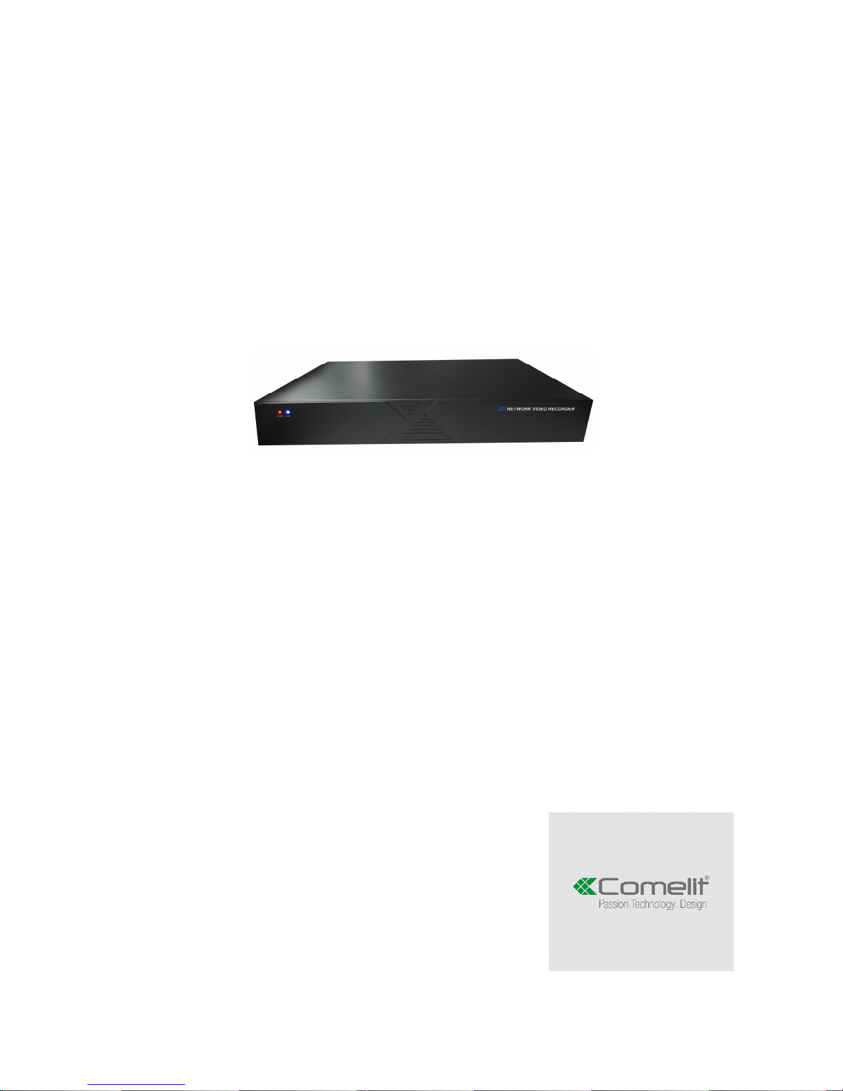
NVR IP 100 SERIES
Please read this manual thoroughly before use and keep it for future reference
Page 2

2
Contents
1.Menu operation ....................................................................................................................................... 4
1.1 Local Operation Guide .................................................................................................................. 4
2. Start/ Shutdown System ......................................................................................................................... 4
2.1 Main menu-Start (Power off, Reboot, Login, Logout) ................................................................... 4
3. Preview ................................................................................................................................................... 5
4. IP Channel setting .................................................................................................................................. 6
4.1 Search IPC .................................................................................................................................... 6
4.2 Add IPC automatically ................................................................................................................... 7
4.3 Add IPC manually ......................................................................................................................... 7
4.4 Channel parameters modification ................................................................................................. 8
4.5 Modify IPC Parameters ................................................................................................................. 9
4.6 Delete IPC ................................................................................................................................... 10
5 System configuration setting ................................................................................................................. 11
5.1 Device parameters setting .......................................................................................................... 11
5.2 Channel parameters setting ........................................................................................................ 12
5.2.1 Display Setting .................................................................................................................. 12
5.2.2 Video Parameters ............................................................................................................. 13
5.2.3 Schedule Record .............................................................................................................. 14
5.2.4 Motion Detection ............................................................................................................... 15
5.2.5 Video lost .......................................................................................................................... 17
5.2.6 Tampering Alarm .............................................................................................................. 18
5.2.7 Video Mask Setting ........................................................................................................... 19
5.3 Network parameters setting ........................................................................................................ 20
5.3.1 Network Setting ................................................................................................................ 21
5.3.2 DNNS Setting ................................................................................................................... 24
5.3.3 NTP Setting ...................................................................................................................... 25
5.3.4 Email Setting ..................................................................................................................... 26
5.4 Alarm&Exception......................................................................................................................... 26
5.4.1 Alarm Input........................................................................................................................ 27
5.4.2 Alarm output ..................................................................................................................... 28
5.4.3 Exception .......................................................................................................................... 29
5.5 Account Setting ........................................................................................................................... 29
5.5.1 User information Setting ................................................................................................ 30
5.5.2 User Online Checking ....................................................................................................... 31
5.6 System administration ................................................................................................................. 32
5.6.1 Device Log ........................................................................................................................ 33
5.6.2 Stream Info. ...................................................................................................................... 33
5.6.3 HDD Setting ...................................................................................................................... 34
Page 3

3
5.6.4 System Update ................................................................................................................. 34
5.6.5 Auto Reboot ...................................................................................................................... 35
5.6.6 Recovery Configuration .................................................................................................... 35
6. PTZ control ........................................................................................................................................... 35
7. Manual record ...................................................................................................................................... 36
8. Manual snapshot .................................................................................................................................. 37
9. Video Playback ..................................................................................................................................... 37
10. Screen Display Setting ....................................................................................................................... 38
11.Video Backup Setting .......................................................................................................................... 39
12. Alarm setting ...................................................................................................................................... 40
13. File Manage ........................................................................................................................................ 40
14. Image Setting ..................................................................................................................................... 41
15.Screen Aspect Ratio/Segmentation .................................................................................................... 42
Page 4
4
1.Menu operation
(default Username: admin / Password:none)
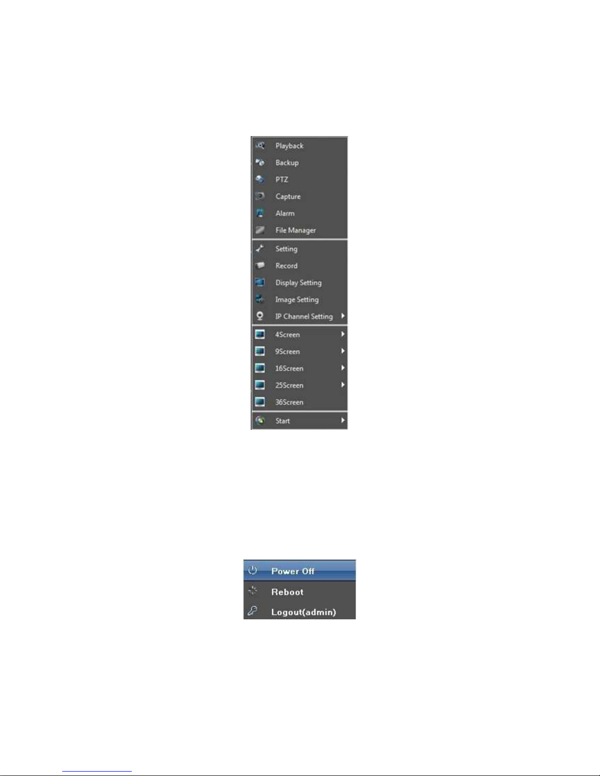
1.1 Local Operation Guide
As picture:
2. Start/ Shutdown System
2.1 Main menu-Start (Power off, Reboot, Login, Logout)
1)Start up:Switch on the power source correctly, and start up the devices
2)Power off:Click"Power off" , the device will shutdown
3)Reboot:Click "Reboot" ,the device will reboot automatically
4
)Logout: Click"Logout" , the device will logout
Page 5

5
3. Preview
Start up the devices, after successfully login the following interface will appear:
Page 6
6
4. IP Channel setting
4.1 Search IPC
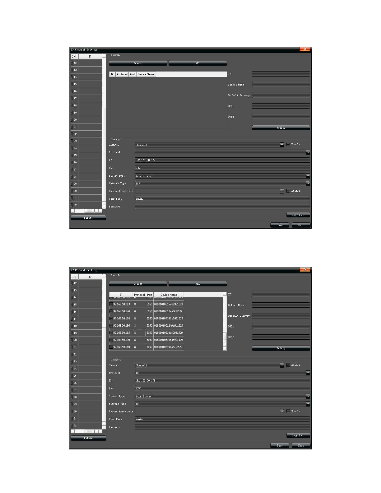
At the page of "IP Channel Setting" , click "Search", the local area network IPC will
appear, and do basic parameters modify , as shown in the below picture:
Page 7
7
4.2 Add IPC automatically
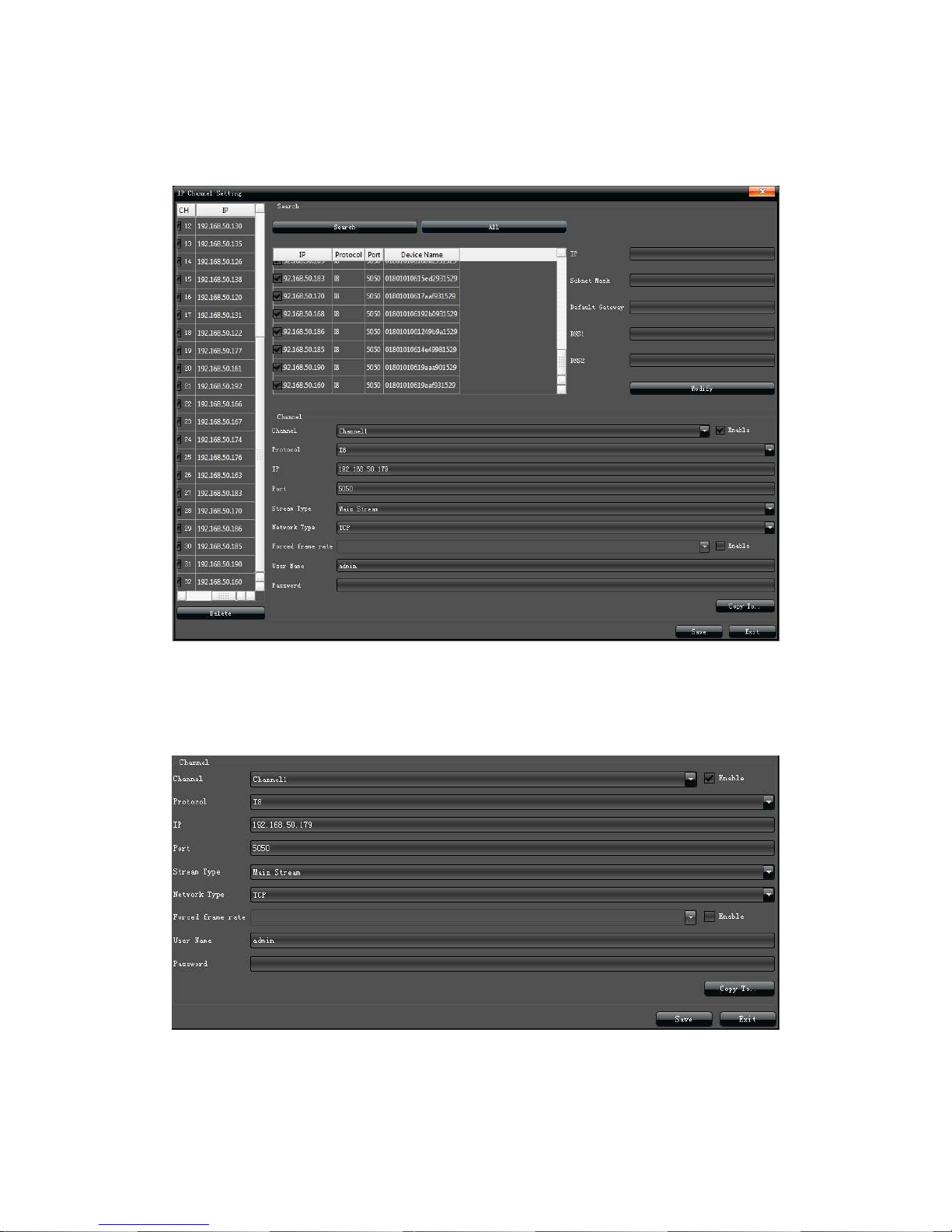
Mark the needed IPC in the "Search menu", the configuration of IP camera will add to
the left channel automatically, then click"save", as shown in the below picture:
(Note:Click "ALL" will add the search menu camera to the left channel in turn)
4.3 Add IPC manually
■ Click "√" in front of "Enable" at the channel item
■ Select relevant protocol
■ Input the IP address
Page 8
8
■ Input the port number
■ Input the user name
■ Input the IPC password, and click "Save" finally
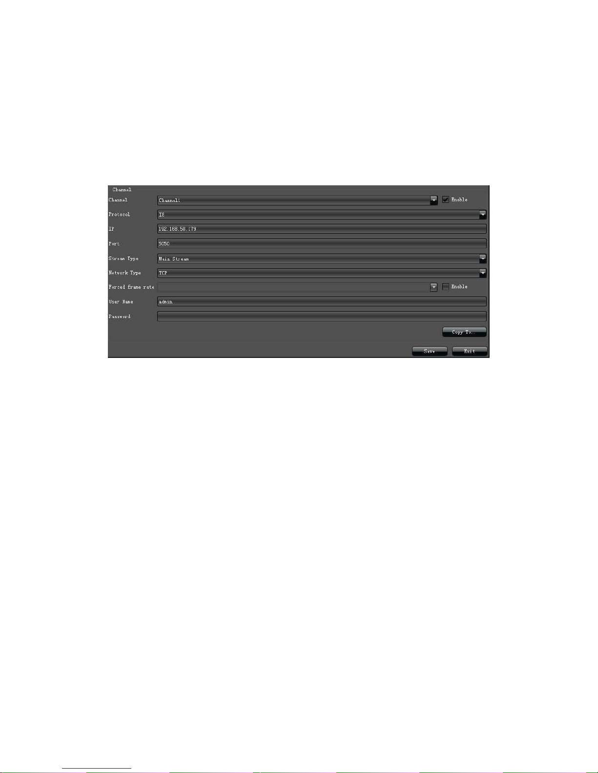
4.4 Channel parameters modification
Double-click the channel parameters which needed to modify on the left "Channel
menu", then input relevant parameters, click"Save", as shown in the below picture:
1)Enable: Select the relevant channel, check "Enable"
2)Protocol: ONVIF Standard protocol/ I8 Private protocol/ I9 Private protocol/ RTSP
Standard protocol for selection
3)IP Add:Edit and modify the IP address manually
4)Port:Edit and set the relevant port number
5)Stream Type: Select "Main Stream" or "Sub Stream"
6)Network type:Select“TCP”or“UDP”
7)User :Input the user name
8)Password:Fill the password in the password field
Page 9
9
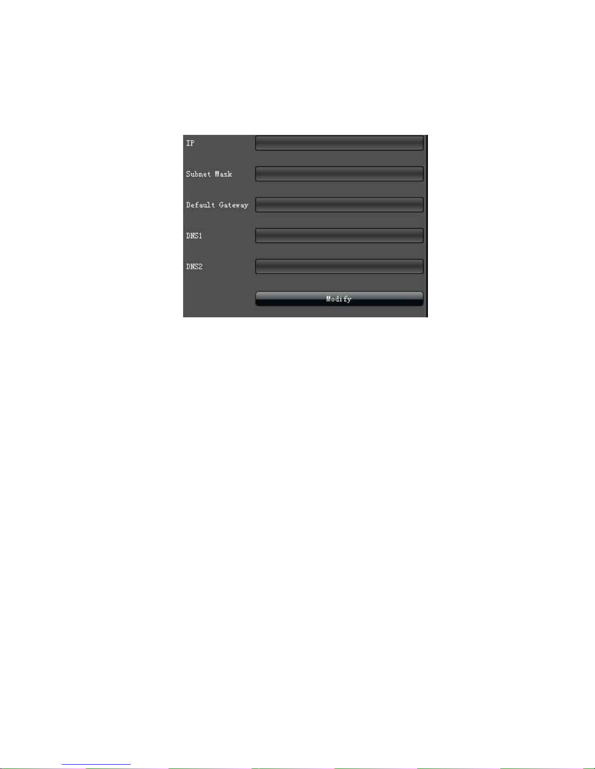
4.5 Modify IPC Parameters
Double-click the channel parameters which needed to modify on the " Channel menu",
then fill in the relevant parameters, click "Modify", as shown in the below picture:
Page 10
10
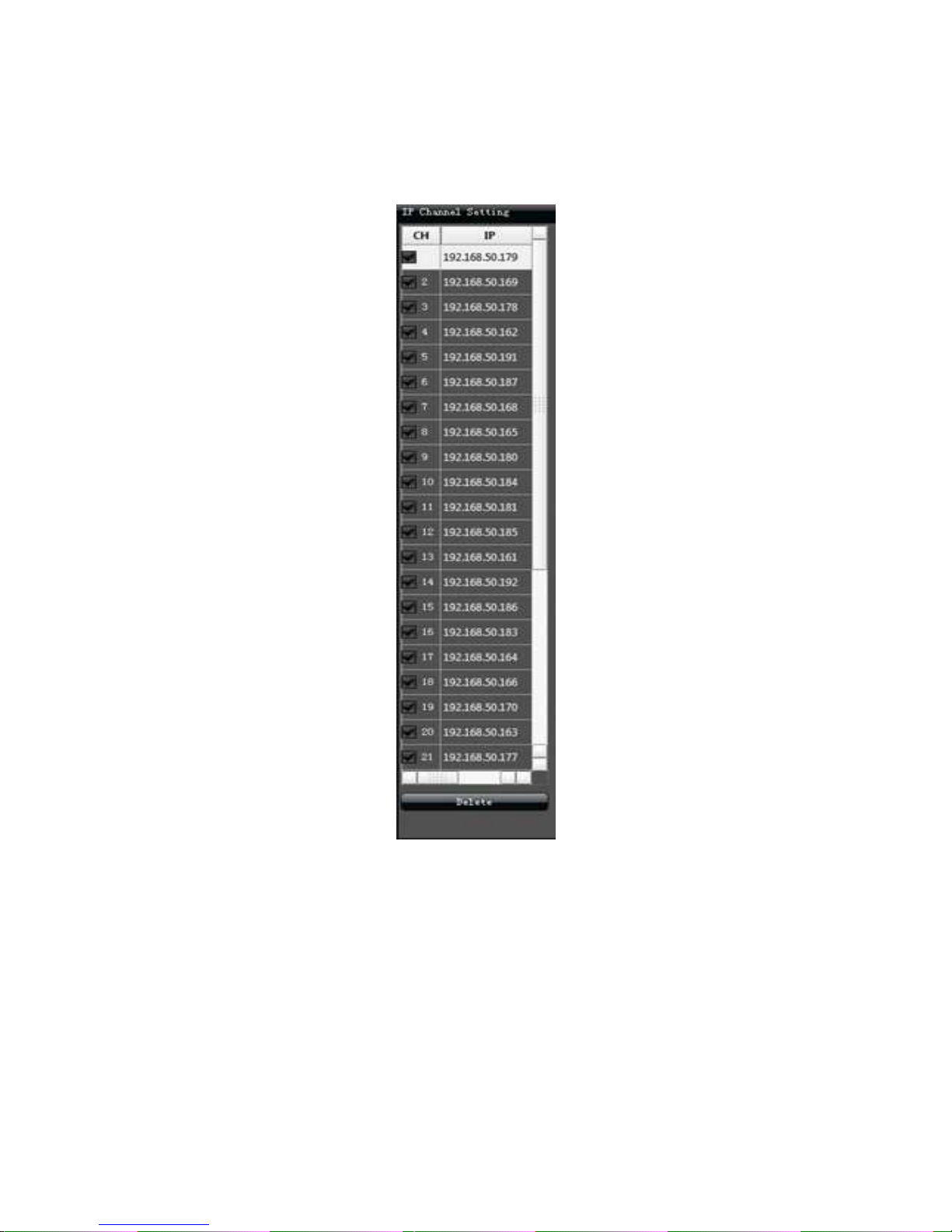
4.6 Delete IPC
Mark the IPC parameters which needed to delete, then click"Delete", as shown in the
below picture:
Page 11
11
5 System configuration setting
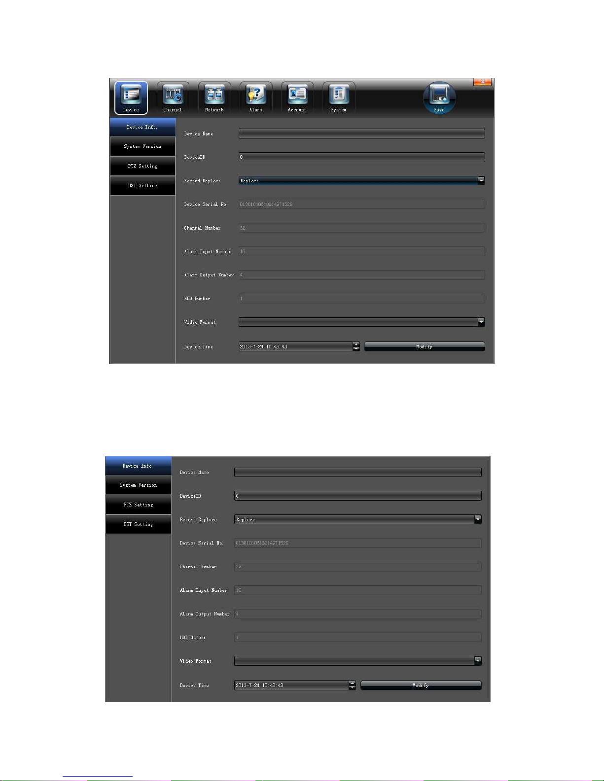
5.1 Device parameters setting
Click "Device parameters" on the "Device Info." interface, then view and modify the
relevant basic information, as shown in the below picture:
1)Device Info.:Check and modify the basic information
Page 12
12
2)System Version:Edit the system version number
3)PTZ Setting:Modify the access dome cameras parameters
4)DST Setting: Enable and set DST parameters
5.2 Channel parameters setting
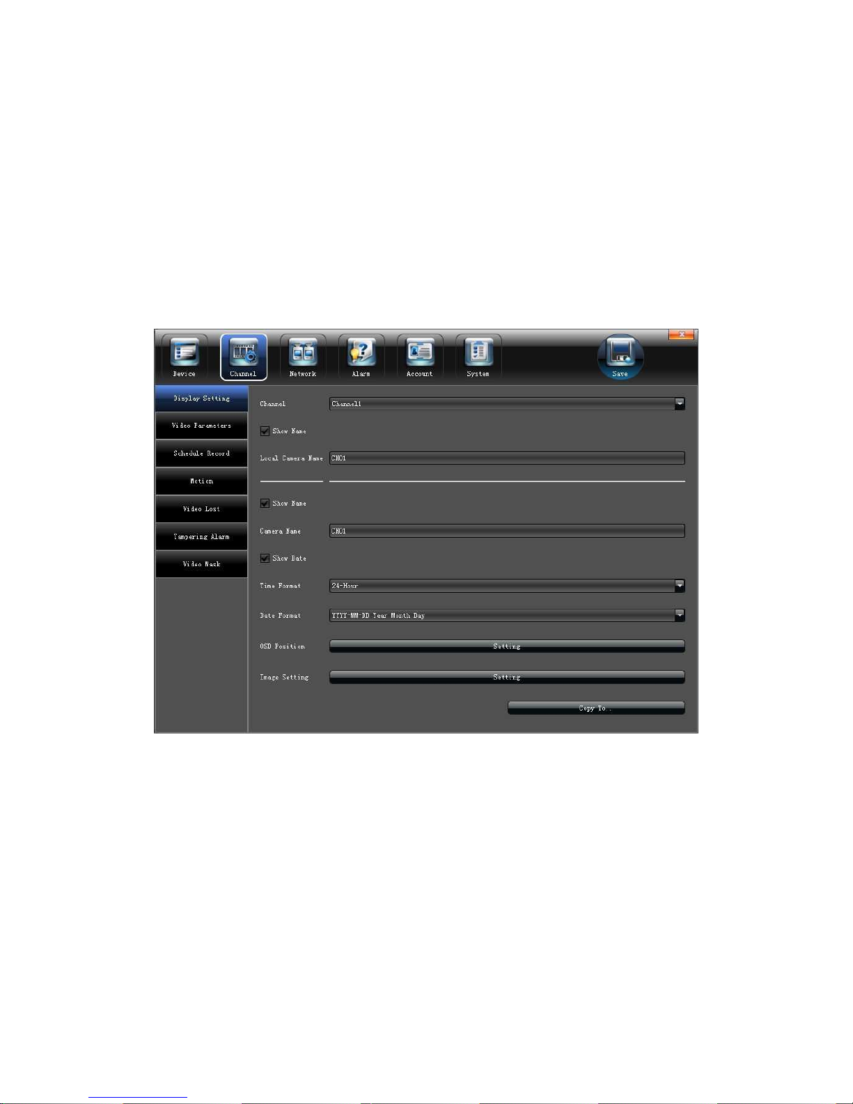
5.2.1 Display Setting
Select the relevant channel and modify the parameters on the "Display Setting"
interface, as shown in the below picture:
1)Channel:Modify the specified channel name
2)Local camera name:Modify the input devices channel name for specified channel
3)Time format:Select time display mode for the access devices
4)Date format:Select date display mode for the access devices
5)OSD Position:Set different display position for the access devices name and
display-time
6)Image Setting:Adjust the access devices brightness and contrast
(Note:Except 1), other options only efficient for privacy protocol equipments)
Page 13
13
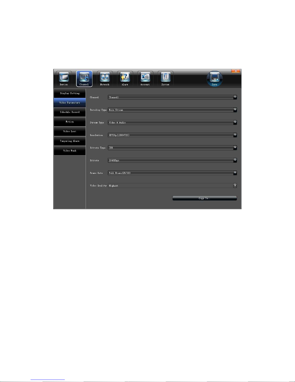
5.2.2 Video Parameters
Modify the relevant channel video parameters on the "Video Parameters"
interface,as shown in the below picture:
1)Channel:Select the channel number
2)Encoding Type: Mani stream/ Sub stream/ Main stream(Event) for selection
3)Stream type:Video&Audio/Video optional
4)Resolution:Several kinds of resolution which IPC supported
5)Bit rate Type: CBR/VBR optional
6)Bit rate: Select relevant bit rate which needed
7)Frame Rate: Select different frame rate from the drop-down list, "FULL"default.
8)Video quality: Different level video quality optional, "Highest" default.
(Note: " Video setting" will be directly modify the IP cameras parameters, and only valid for
private protocol linkage channel)
Page 14
14
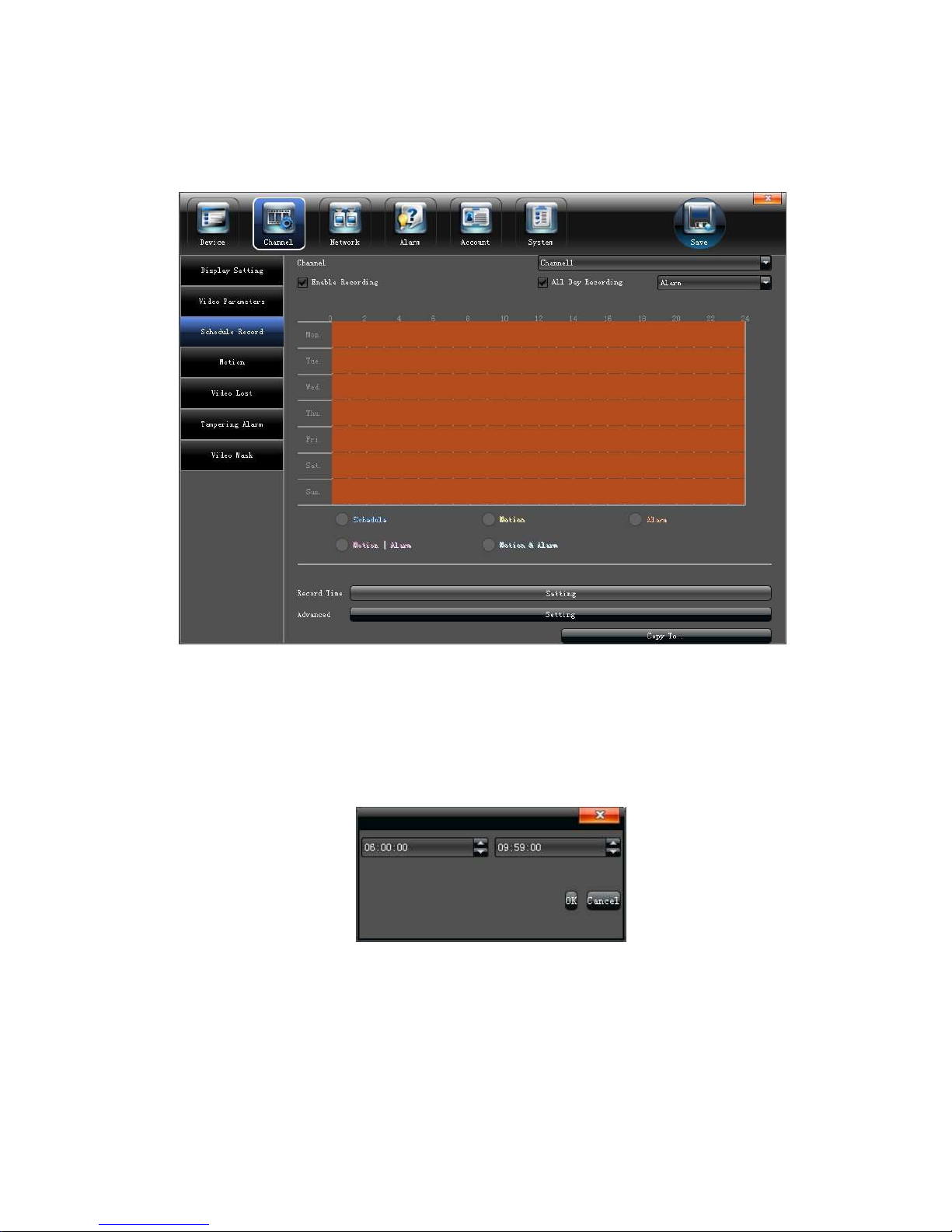
5.2.3 Schedule Record
Modify each video channel parameters on the "Schedule Record" interface,as
shown in the below picture:
5.2.3.1 Video precise backup
Double-click the time bar to set precise video backup, there will be a small check
appear, and then double-click the small check, the following interface will pop-up(The check
box in front of "All Day Recording" can not mark ):
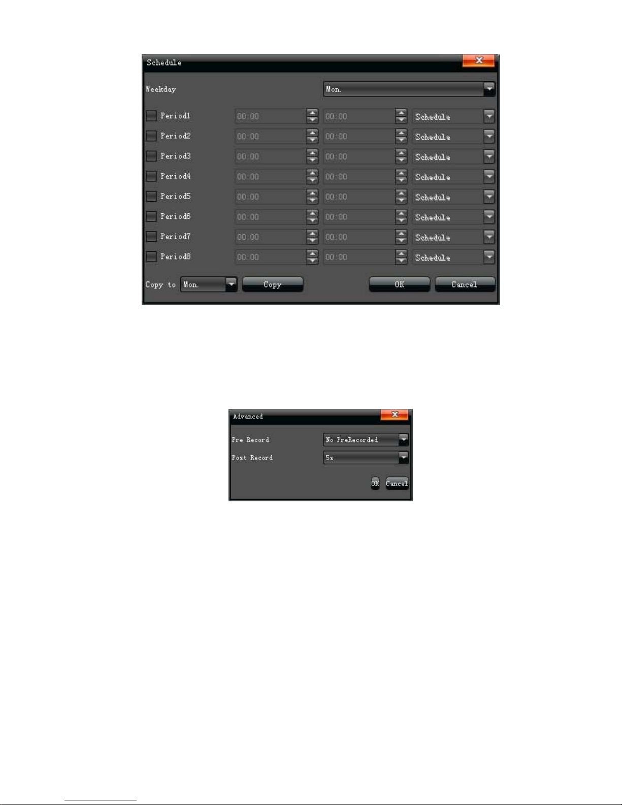
5.2.3.2 Record time
Click "Setting" to do period time recording on the "Schedule " interface, as shown in the
below picture:
Page 15
15
(Note:It can set 8 periods video recording mode during one day)
5.2.3.3 Advanced Record
Set relevant advanced recording parameters for each channel on the " Advance"
interface, as shown in the below picture:
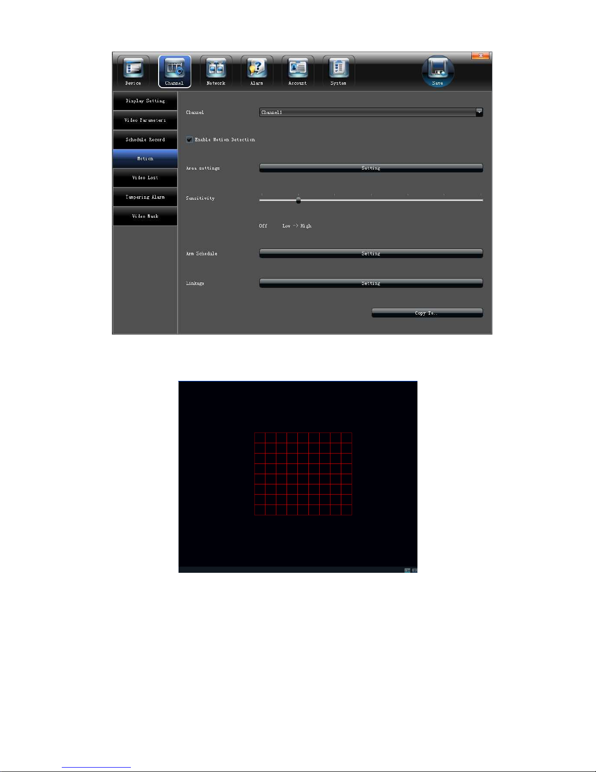
5.2.4 Motion Detection
(Note:Fore-end IP Camera must support motion detection)
Modify each video channel parameters on the "Motion" interface,as shown in the
below picture:
Page 16
16
1)Click "√" in front of "Enable Motion Detection"
2)Set motion areas, as shown in the below picture:
3)Adjust sensitivity volume
4)Set arm schedule
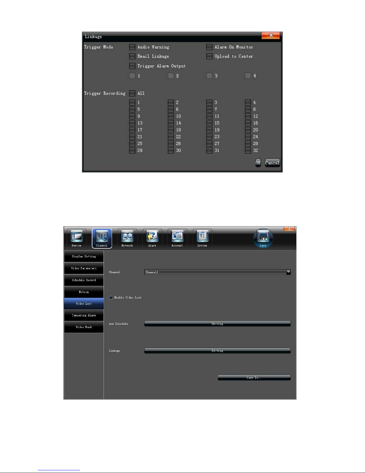
5)Select trigger mode, as shown in the below picture:
Page 17
17
5.2.5 Video lost
Modify each video channel parameters on the "Video lost" interface,as shown in the
below picture:
1)Click "√" in front of "Enable Video Lost"
2
)Set arm schedule
Page 18
18
3)Select trigger mode, as shown in the below picture:
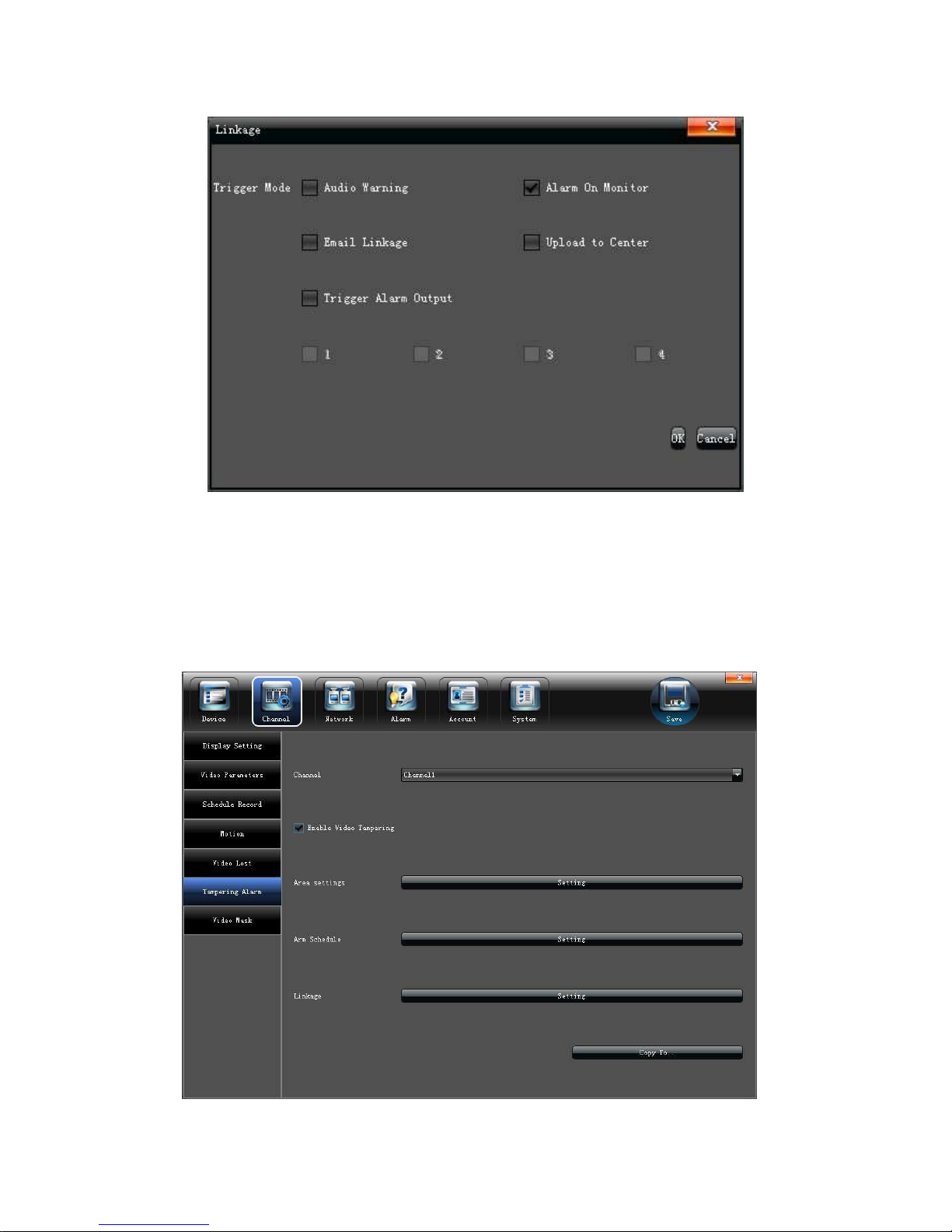
5.2.6 Tampering Alarm
(Note:Fore-end IP Camera must support tampering alarm)
Modify each video channel parameters on the "Tampering Alarm" interface,as
shown in the below picture:
1)Click "√" in front of "Enable Video Tampering"
Page 19
19
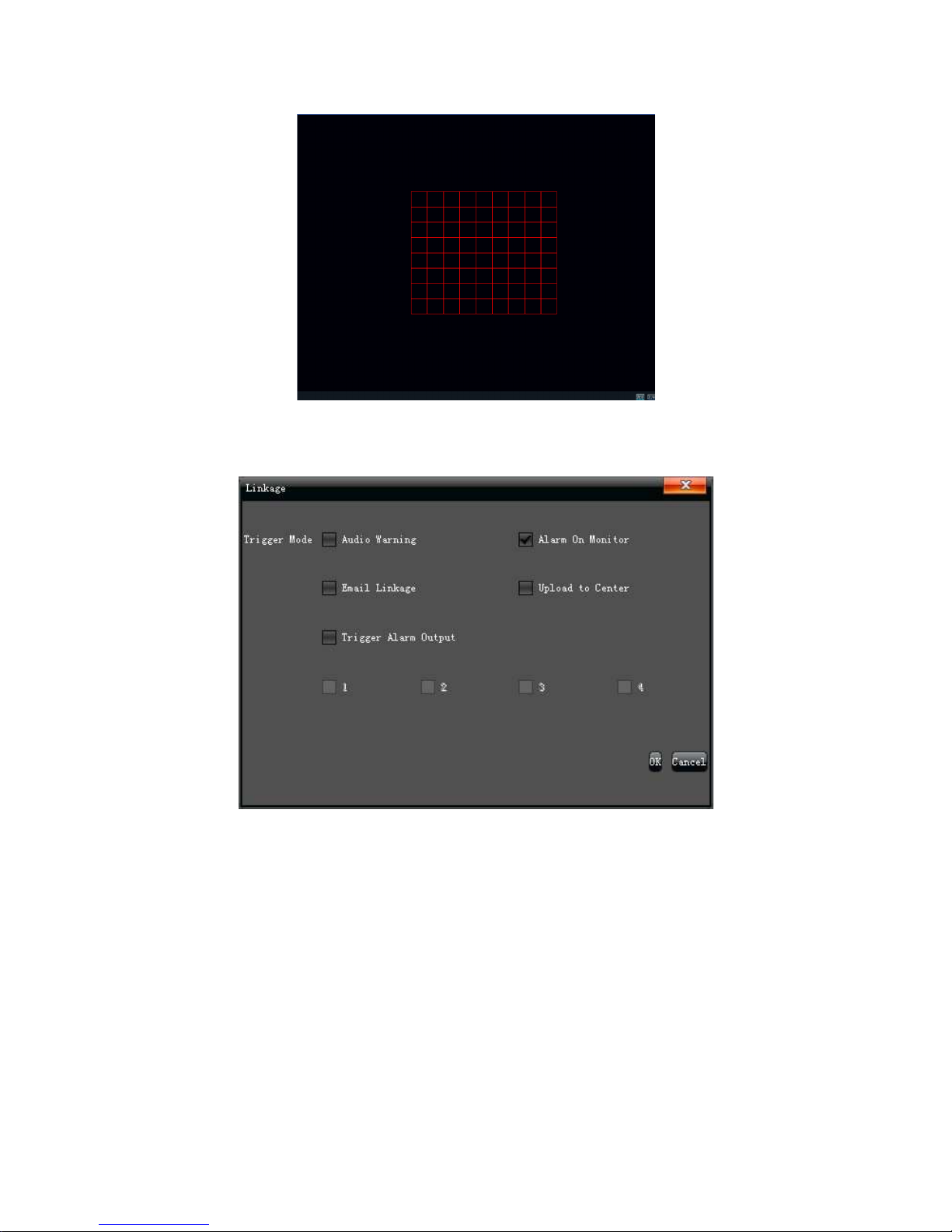
2)Area setting, as shown in the below picture:
3)Set arm schedule
4)Select trigger mode, as shown in the below picture:
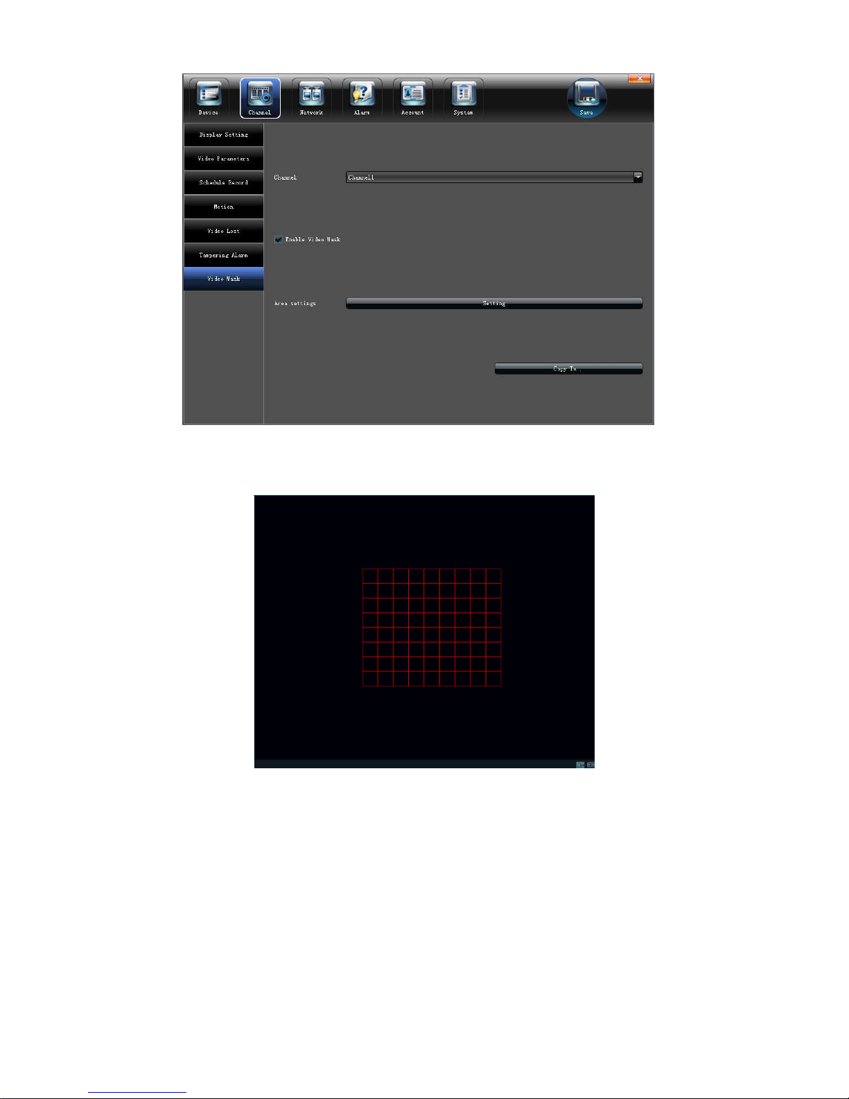
5.2.7 Video Mask Setting
Modify each video channel parameters on the "Video Mask" interface,as shown in
the below picture:
Page 20
20
1)Click "√" in front of "Enable Video Mask"
2)Set mask areas, as shown in the below picture:
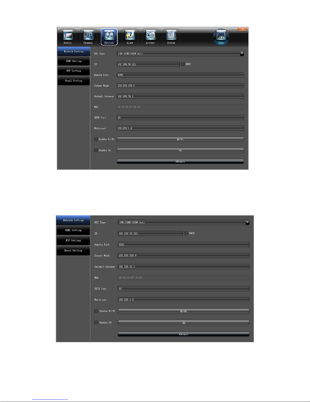
5.3 Network parameters setting
Set the relevant parameters according to the need on the "Network" interface, as
shown in the below picture.
Page 21
21
5.3.1 Network Setting
Modify the basic network parameters on the "Network setting" interface, as shown in
the below picture:
1)NIC Type:Select diverse network card according to the need
2
)IP:Input the relevant IP address number(IP:192.168.1.180 default)
Page 22
22
3)DHCP:Click "√" in front of "DHCP", it will acquire a valid IP automatically according to the
router DHCP
4)Device Port: Input relevant device port number (5050 default)
5)Subnet Mask: Input relevant IP subnet mask number
6)Default Gateway: Input relevant default gateway
7) DNS1 and DNS2: Administer main machine to realize DVR register to the servers
automatically
8)MAC:Display present MAC address
9)HTTP Port:Input relevant port number (80 default)
10)Multicast: Edit relevant multicast address
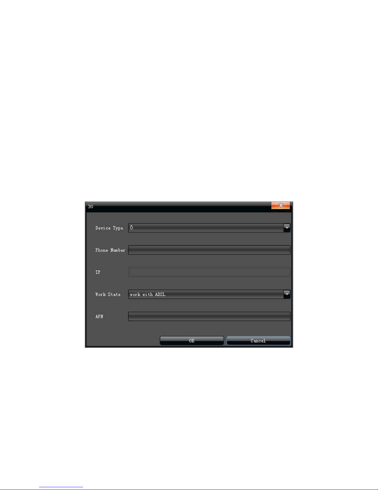
11)3G:Click "√" in front of "Enable 3G" after link 3G external attachment, relate device type,
edit relevant phone number, and select work state, click "OK" after setting, as shown in the
bellow picture:
Page 23
23
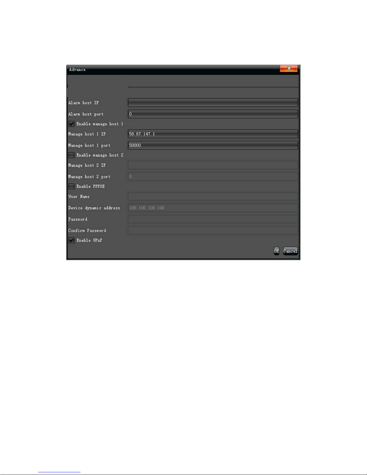
5.3.1.1 Advanced setting
Set advanced configuration parameters on the "Advance" interface, as shown in the
below picture:
1) Enable PPPOE function to achieve NVR dialing
2) Click "√" in front of " Enable UPnP",and setup HTTP port and TCP port it can match
successfully, notice the port number can not conflict with other devices.
Page 24
24
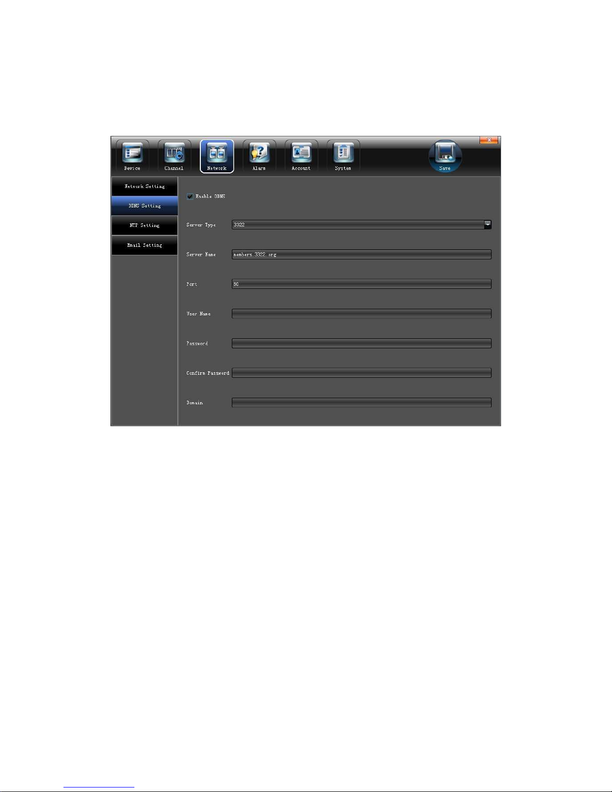
5.3.2 DNNS Setting
Through the DDNS server, there should be a PC with fixed IP address on the internet, and
run this DDNS server on it.
1) Select DDNS server type(ex. ComelitDNS)
2) Input the server name (ex. “update.comelitdns.com”)
3) Input the port
4) Input the user name
5) Input the password (10 char. max)
6) Confirm the password
7) Input the domain name (ex. Hostname.comelitdns.com)
To use the ComelitDNS service see the end of this manual.
Page 25
25
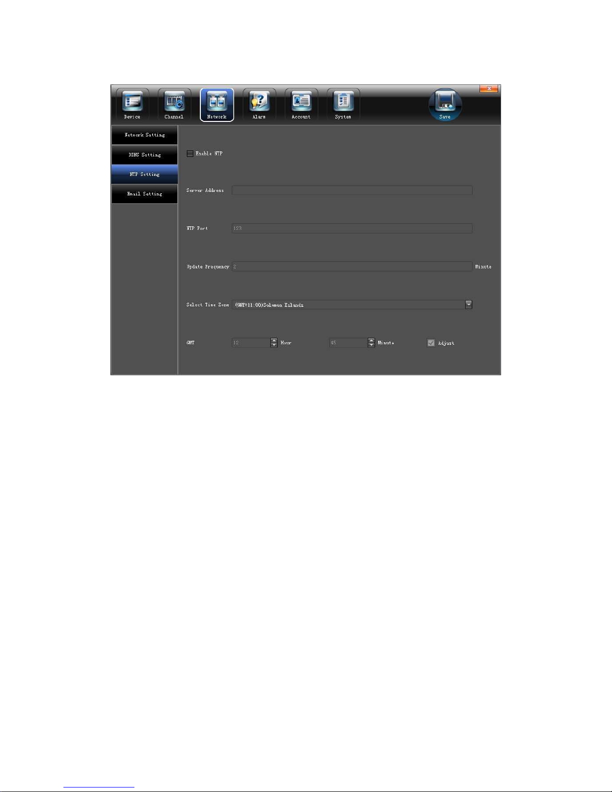
5.3.3 NTP Setting
1)Server Address: Input the IP of the NTP server
2)NTP Port: This NTP only supports TCP transmission. It is default to 123
3)Update Frequency:Input the time interval needed to be adjusted
4)Select Time Zone:Select the time zone of different places
5)GMT: Do fine adjustment of time
Page 26
26
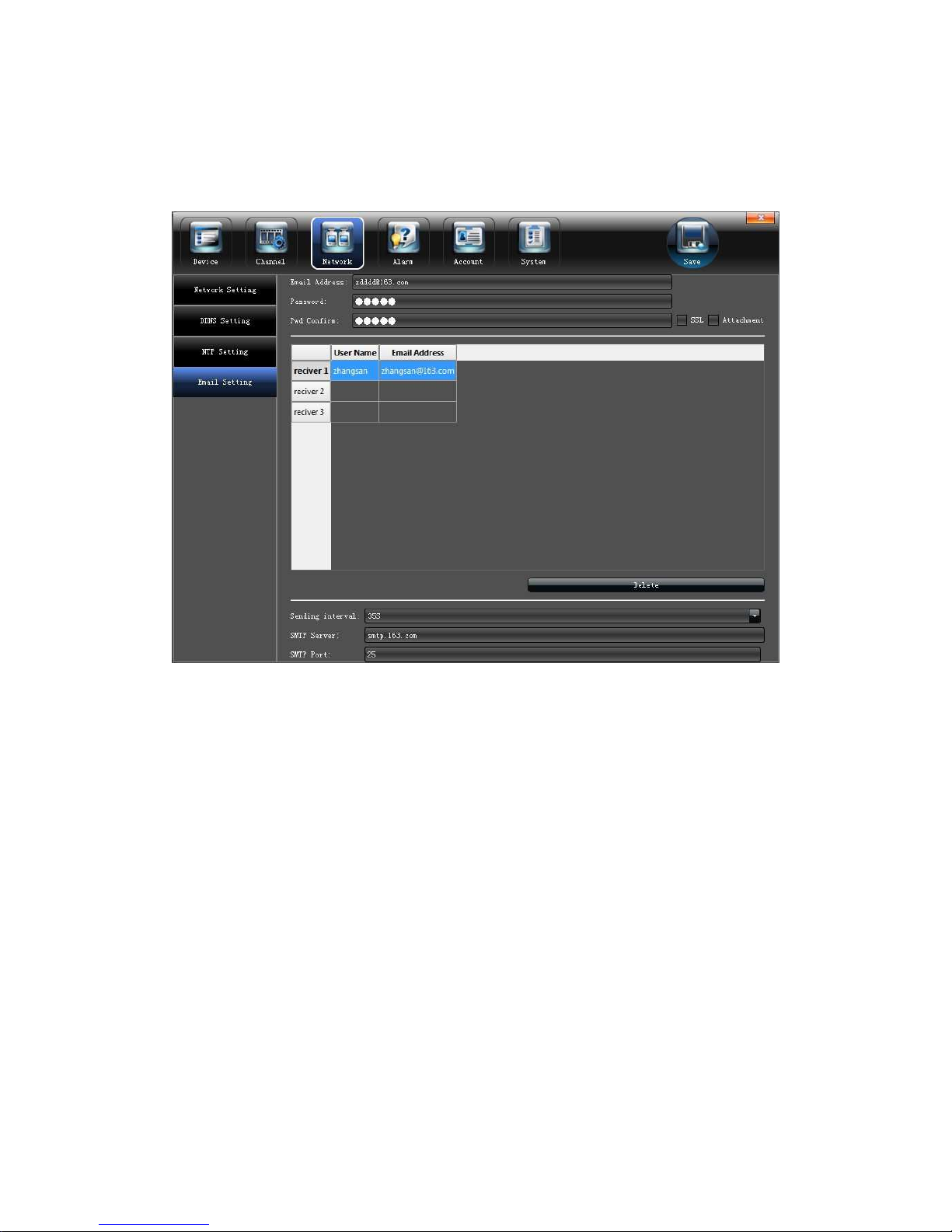
5.3.4 Email Setting
Set up alarm linkage E-mail on the " Email Setting" interface,as shown in the below
picture:
5.4 Alarm&Exception
Set the relevant parameters according to the need on the "Alarm" interface, as shown
in the below picture:
Page 27
27
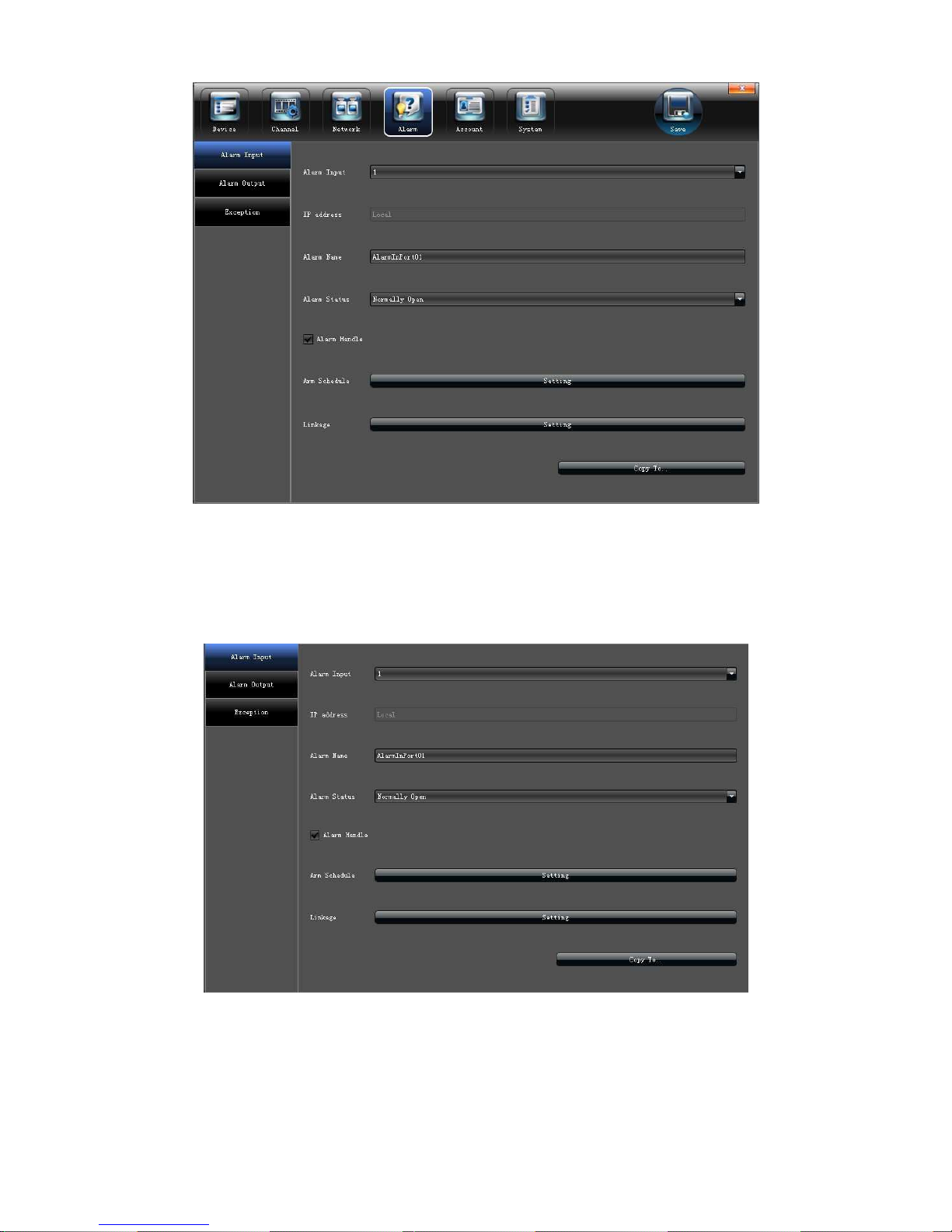
5.4.1 Alarm Input
Set alarm input parameters on the "Alarm Input" interface, as shown in the below
picture:
1)Enable alarm processing
2)Set arm schedule
3)Select trigger mode, as shown in the below picture:
Page 28
28
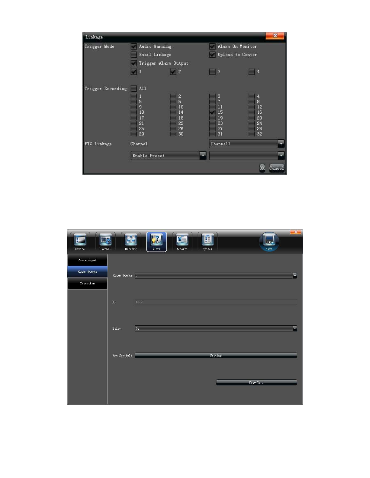
5.4.2 Alarm output
Set alarm output parameters on the "Alarm Output" interface, as shown in the
below picture:
1)Set alarm output delay
2
)Set alarm schedule
Page 29
29
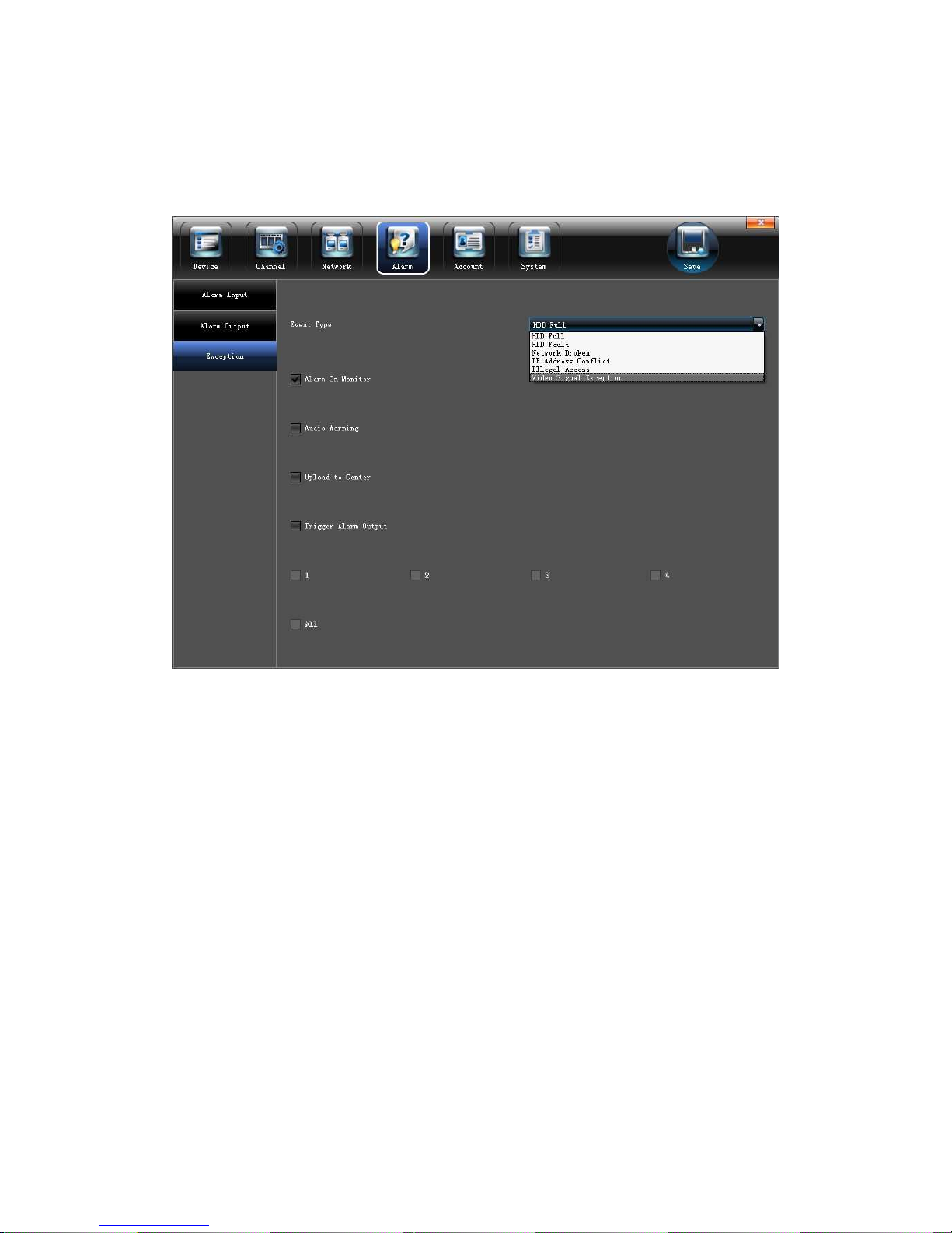
5.4.3 Exception
Set abnormality on the "Exception" interface, as shown in the below picture:
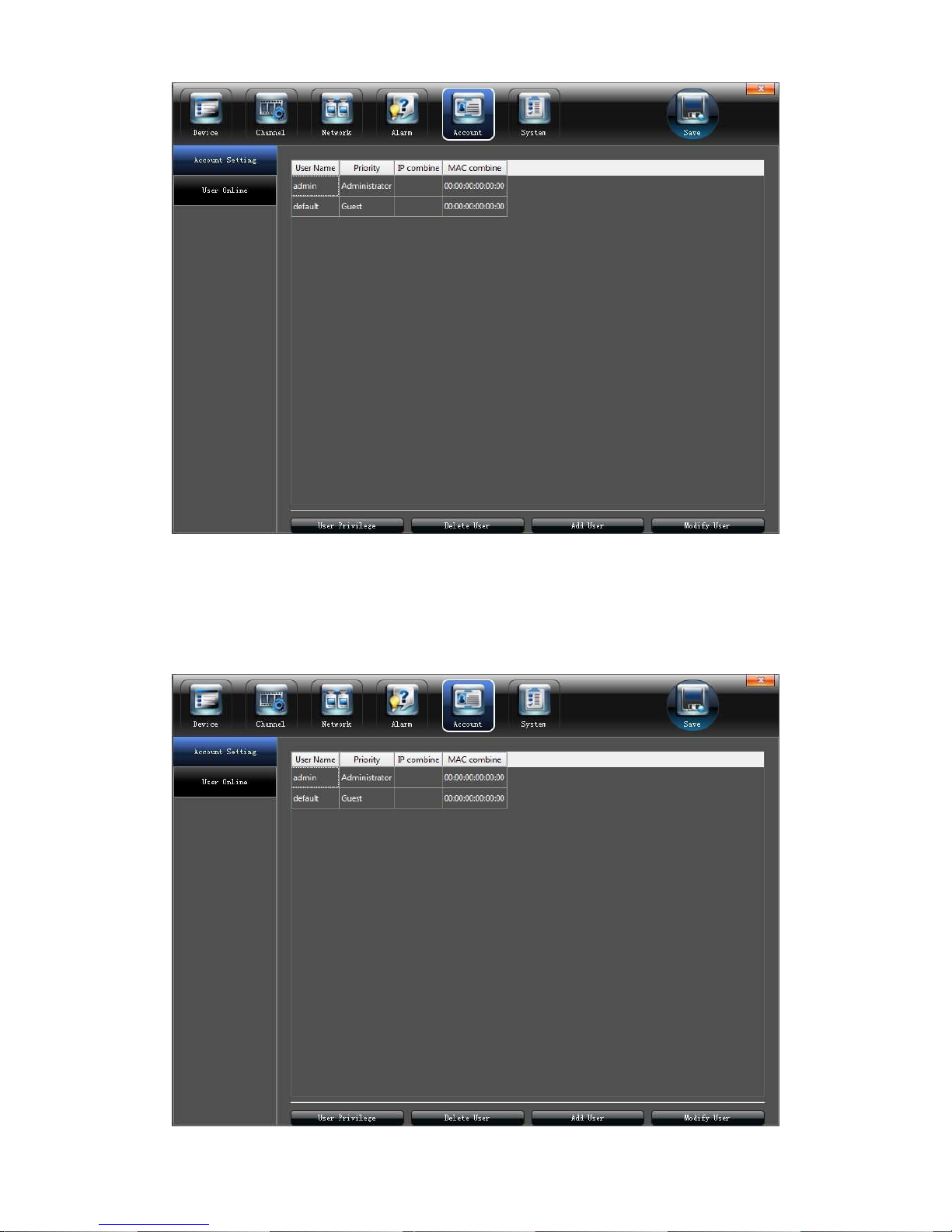
5.5 Account Setting
Set the relevant parameters according to the "Account" interface, as shown in the
below picture:
Page 30
30
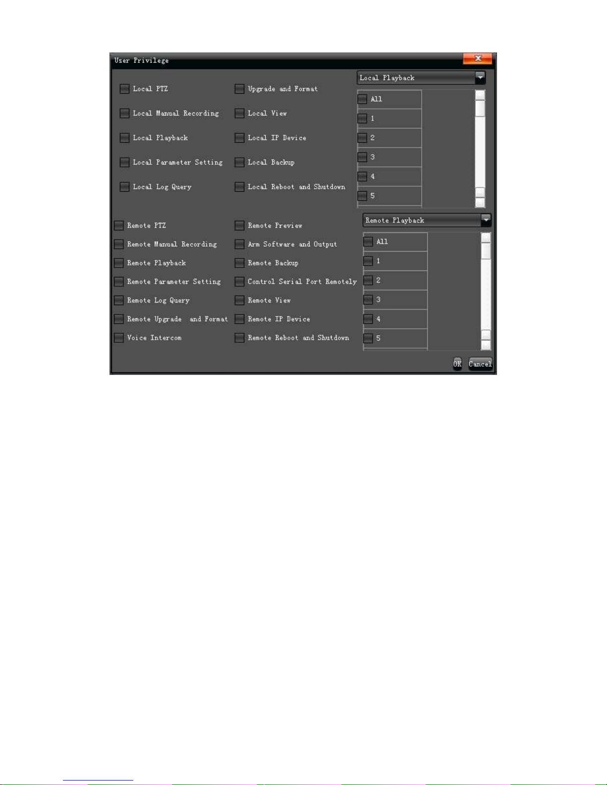
5.5.1 User information Setting
Modify /Add/Delete the user or distribute user permission on the " Account Setting"
interface, as shown in the below picture:
Page 31
31
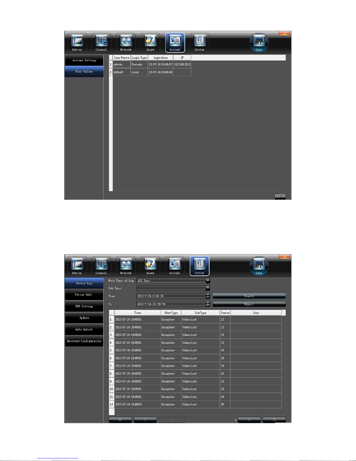
5.5.2 User Online Checking
Check the current user connection status on the "User Online" interface, as shown
on the below picture:
Page 32
32
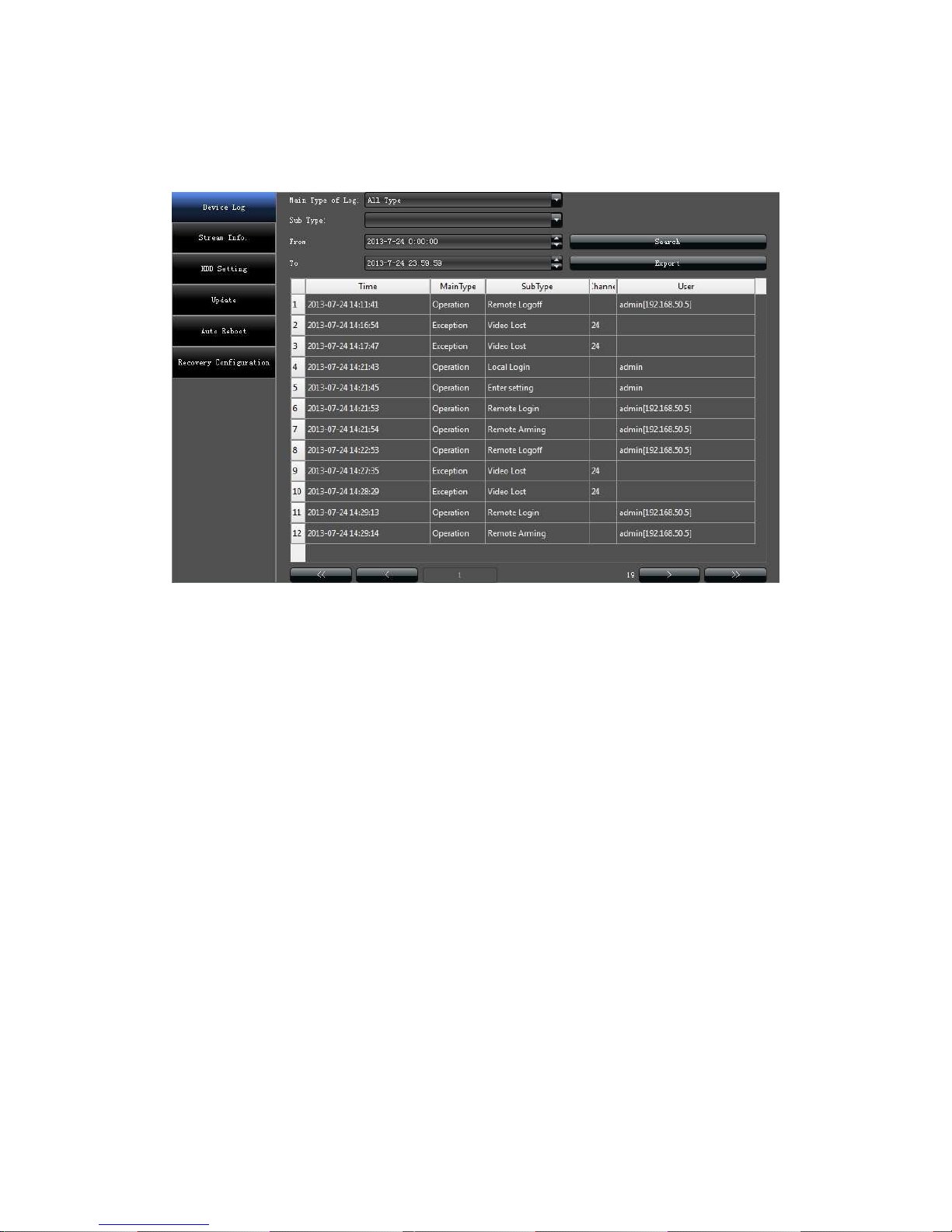
5.6 System administration
Set the relevant parameters according to the "System" interface, as shown in the below
picture.
Page 33
33
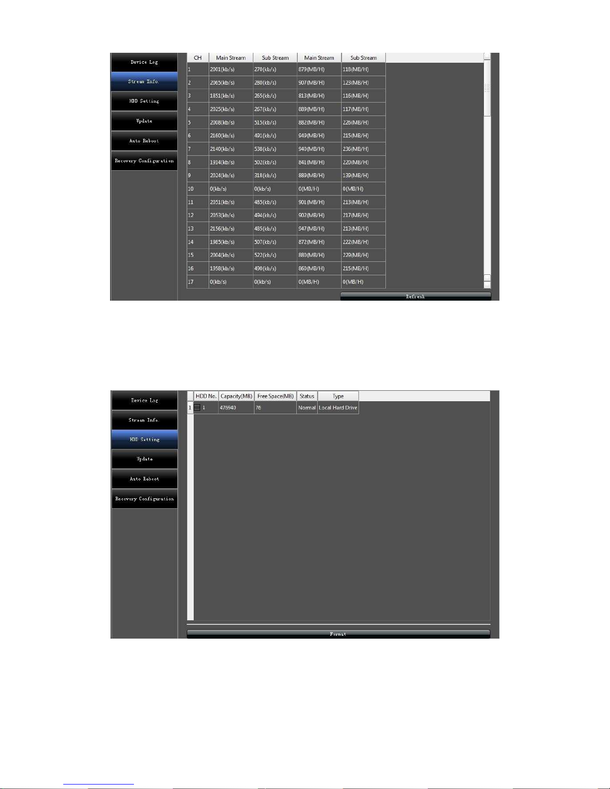
5.6.1 Device Log
Click "Device Log" on the "System" interface, check device log according to the video
type and date time, as shown in the below picture:
1)Main Type of Log: All Type/ Alarm/ Exception/ Operation for selection
2)Sub Type: According to the different main types, have corresponding sub type for
selection
3)From: Select a start time for log query
4)To: Select a end time for log query
5)Export: Export and display all query results
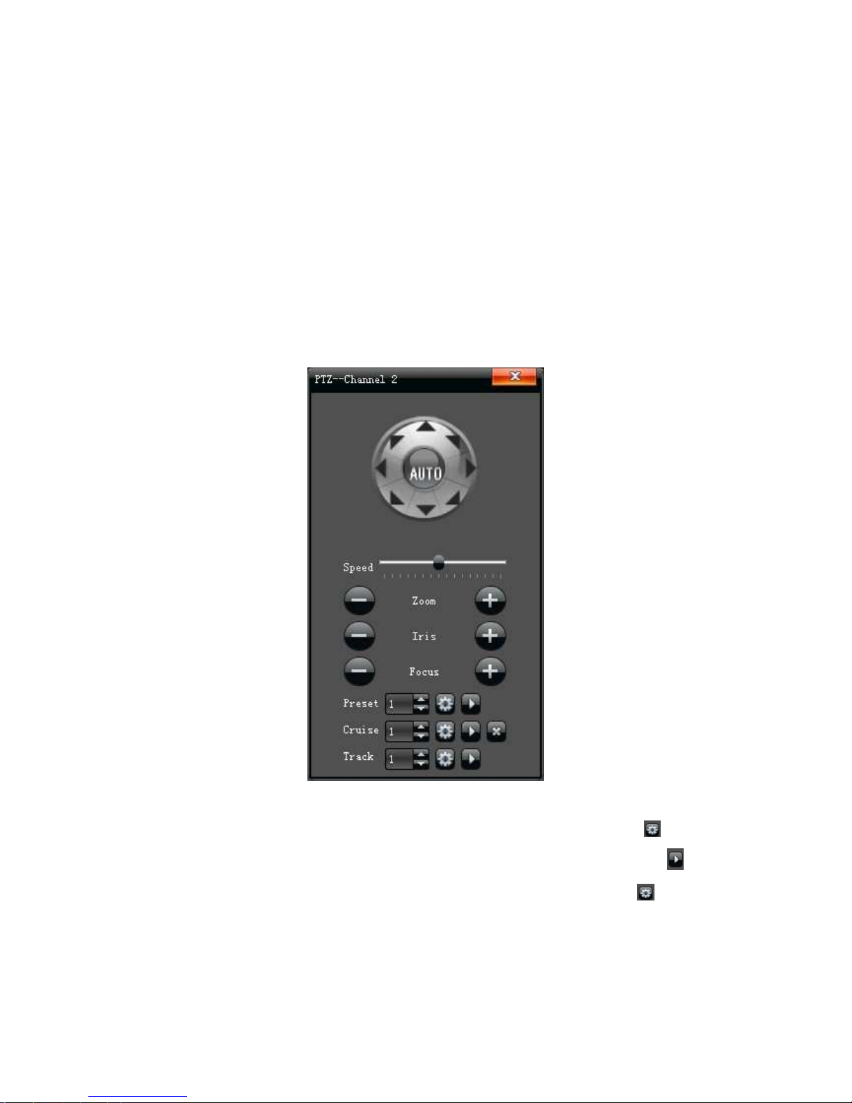
5.6.2 Stream Info
View the stream information of each current channel on the "Stream Info." interface, as
shown in the below picture:
Page 34
34
5.6.3 HDD Setting
Click “HDD Setting”, check HDD capacity / free space, and do format by click “√” in front of
HDD No. , as shown in the below picture:
5.6.4 System Update
Browsing the upgrade file on the “Update”, click “Upgrade” to do software update.
Page 35
35
5.6.5 Auto Reboot
There are Disable/ Every Day/ Every week/ Once options for selection, the device will
restart according to the maintenance mode.
5.6.6 Recovery Configuration
Click “Export Configuration”/“Import Configuration”/ “Default” to make device do
corresponding operation.
6. PTZ control
1)"Preset” setting: Rotate the camera to appropriate angle and position by PTZ
directional buttons, select a preset number in the drop-down list, and click " "button.
Call preset:Select a needed preset number in the drop-down list, and click" " button.
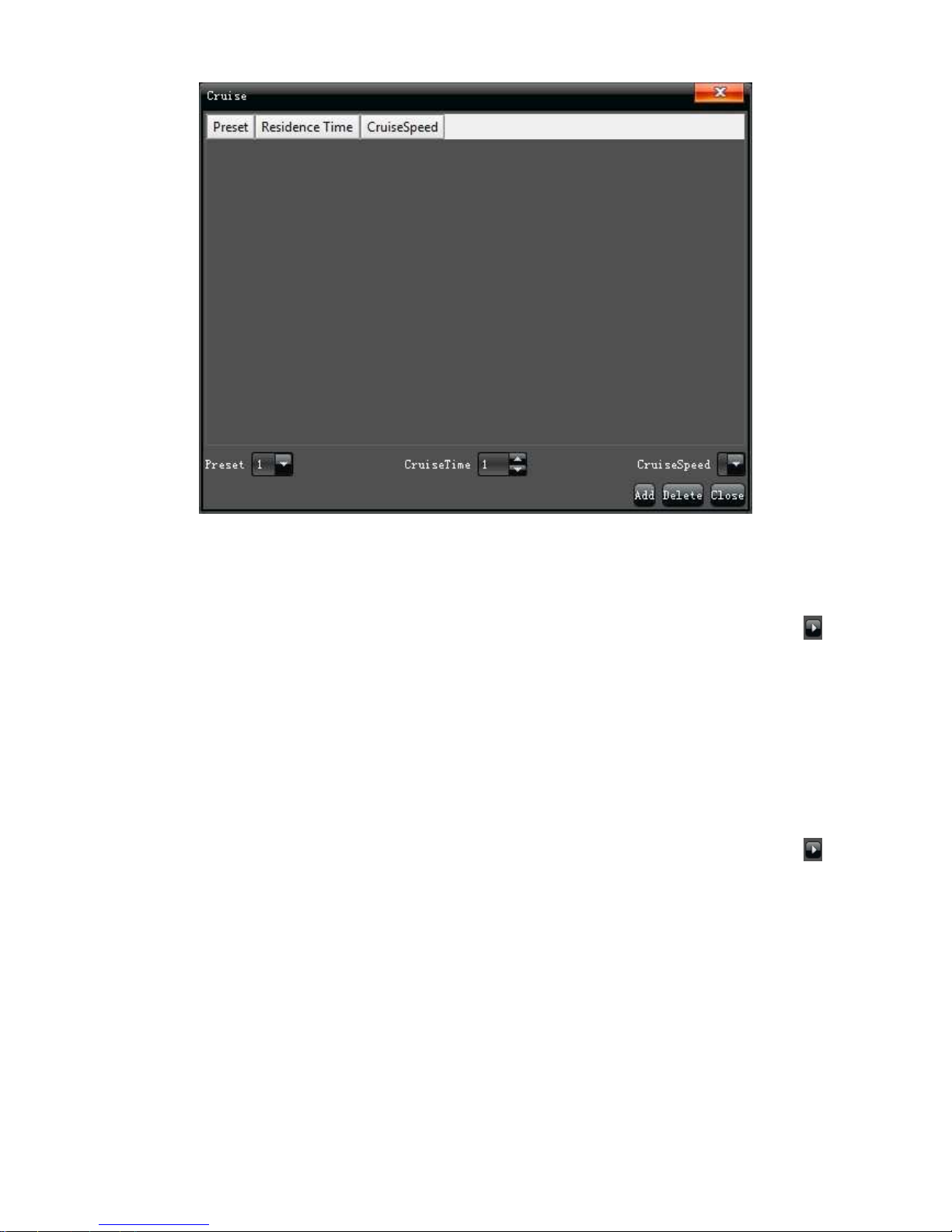
2)"Cruise" setting:select a cruise number in the drop-down list, and click " "button, the
following interface will pop-up:
Page 36
36
On the "Cruise" interface ,Set preset, residence time, cruise speed, and click
"Add" to add new cruise preset( support multiple presets) , click"Delete" to clear
the preset.
Call cruise: Select a needed cruise number in the drop-down list, and click" "
button.
Cruise delete: Select a needed cruise number in the drop-down list,and click "
delete" to clear the cruise.
3)"Track" setting: Select a track number in the drop-down list, click track start
buttons to make PTZ operation, and click again to finish, track memory
operate successfully.
Call track: Select a needed track number in the drop-down list, and click" "
button.
7. Manual record
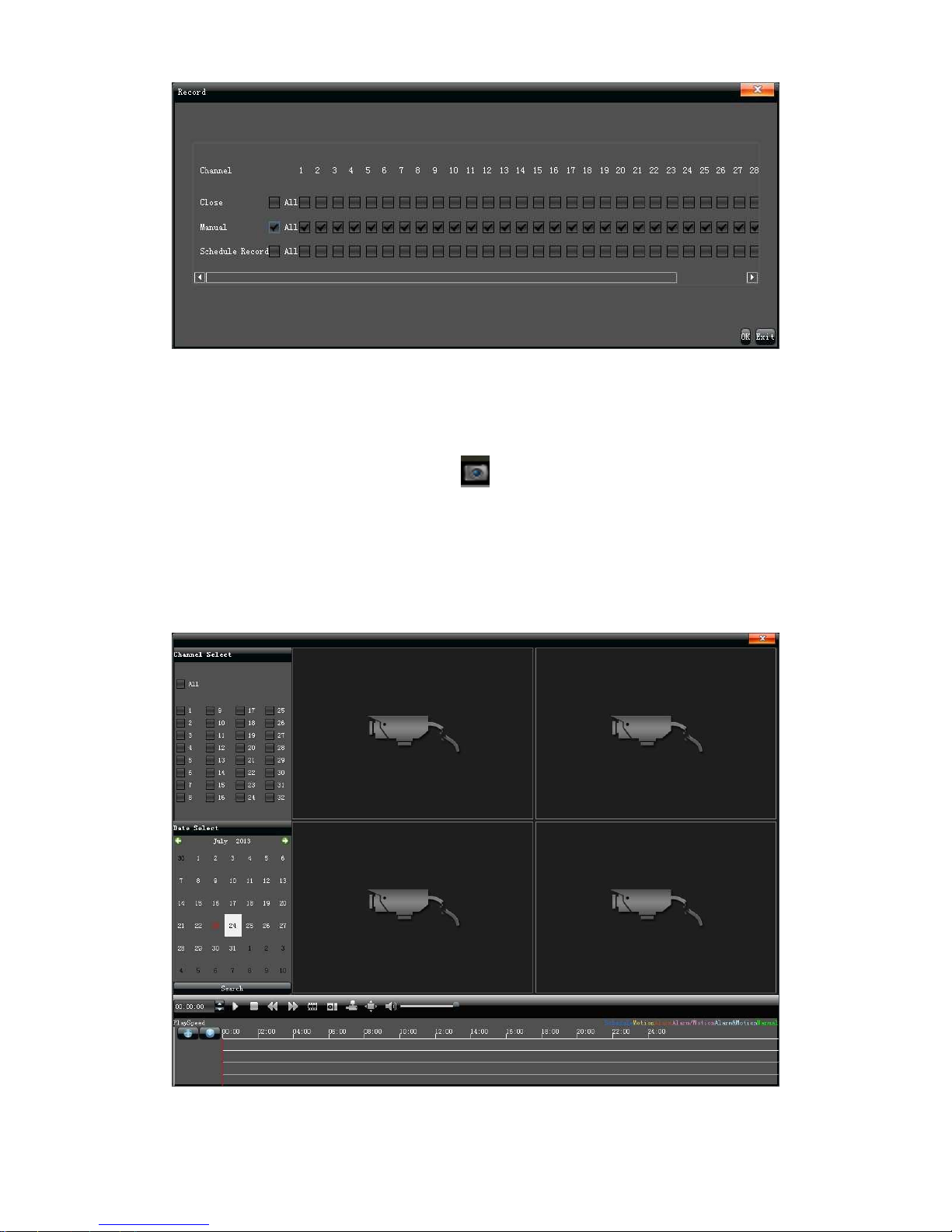
Manual recording have highest priority, whatever state of each channel at present,click
"Manual" ,then all of the corresponding channel will do ordinary record,as shown in the
below picture:
Page 37
37
8. Manual snapshot
Select "Capture" on the main menu, Click” “in the lower right corner of the screen to do
snapshot on the preview channel, and check the image picture in the file manager.
9. Video Playback
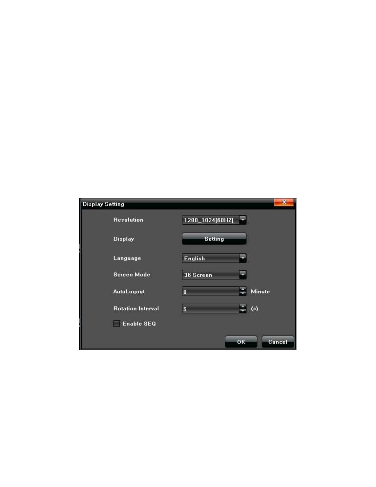
Select "Playback" on the main menu to enter into channel select interface, check
needed replay channels and the video image will retrieve automatically, as shown in the the
below picture:
1)Pause: Pause the current playback
2)Stop: Stop the current playback
Page 38
38
3)Slow:Slow down the playback speed (1/2、1/4、1/8、1/16 times optional)
4)Fast:Speed up the playback process(2、4、8、16 times optional)
5)Snapshot: Can be snapshot for any playback channel
6)Frame play:Sigel frame to play
7)Backup:Make video backup for any channel
8)Full screen: Video image playback with full screen
9)Volume:Adjust the volume of playback audio
Double-click channel bar or click "Play" button to play the backup video , double-click single
channel screen to get full screen display
10. Screen Display Setting
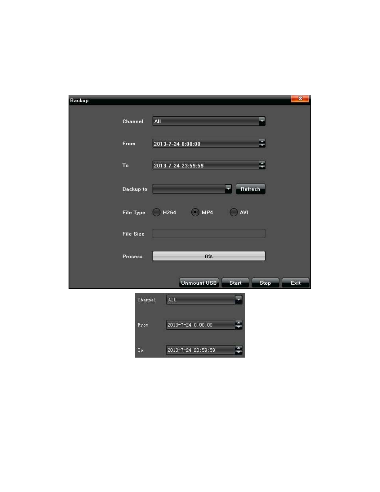
Select “ Display Setting” in the main menu, the following interface will pop-up
1)Resolution:Select different resolution according to the need
2)Display: Adjust the brightness/ contrast/ saturation/hue of the video screen display
3)Language: Different kinds of languages for selection (Simple Chinese, English, French,
etc.)
4)Screen Mode: 1/4 /9 /16 Screen for section
5)Auto Logout: It will logout automatically with no operation during setting minutes
6
)Rotation Interval: Set rotation interval time(seconds), Click “√” in front of “ Enable SEQ”
to make video image rotation automatically
Page 39
39
11.Video Backup Setting
Select "Backup" in the main menu, click" Refresh" after link USB external attachment to
test if USB devices identified normally, when it identified normally the following
information page will display:
Channel:Select relevant channel in the drop-down list according to the need
From:Select a start time for video backup
To:Select a end time for video backup
Click" Start" to make corresponding channel video backup, and show the backup
process meanwhile.
Page 40
40
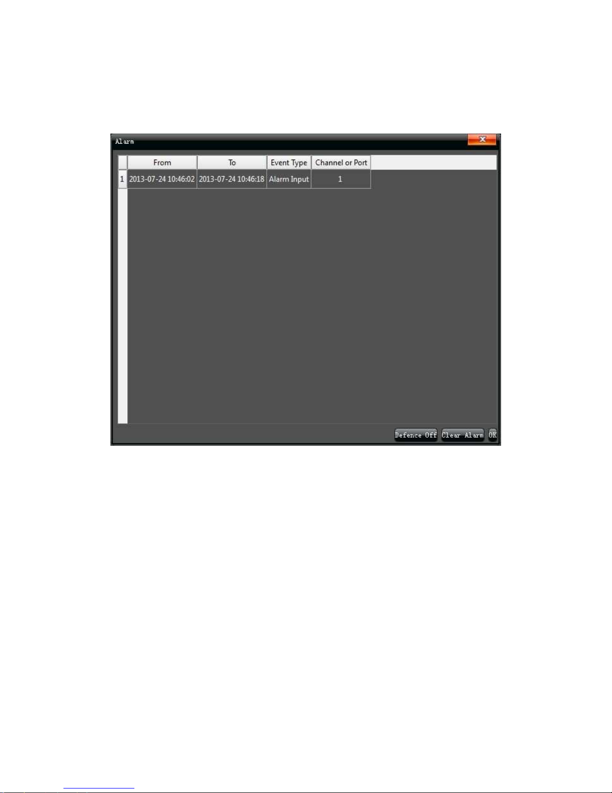
12. Alarm setting
Select "Alarm" in the main menu, all the devices alarm information will appear on the
list, as shown in the below picture:
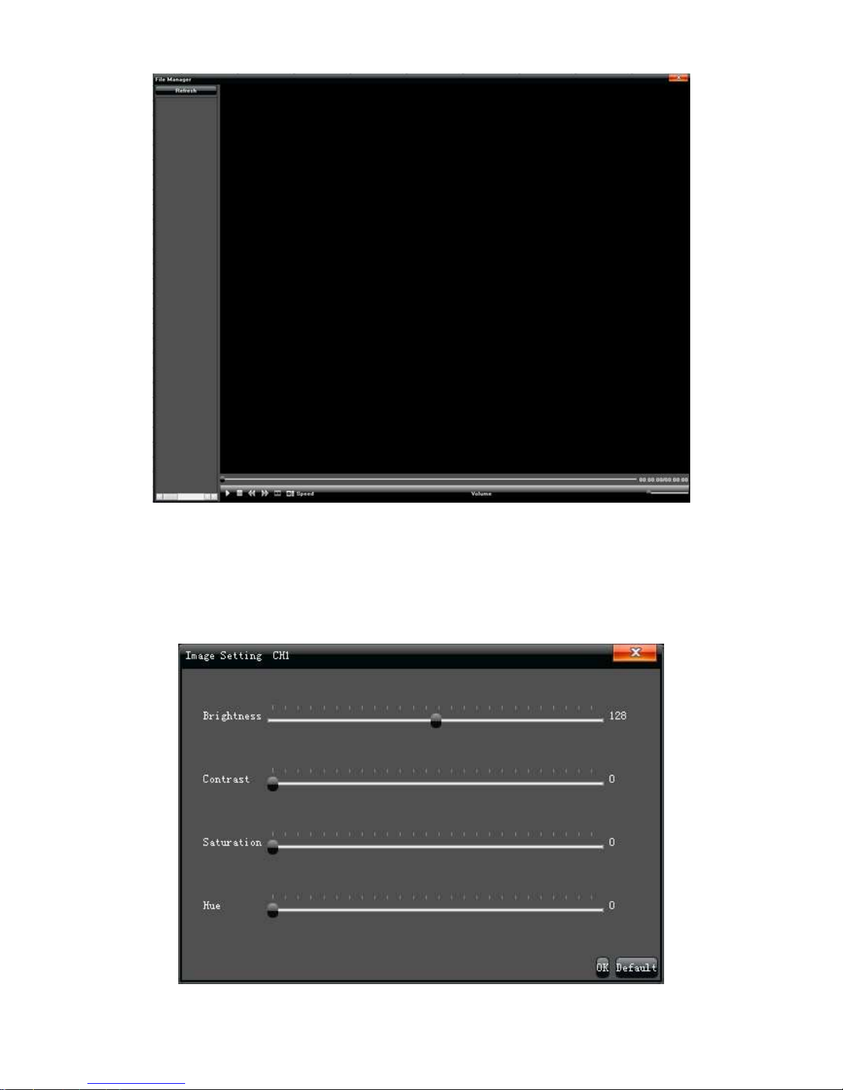
13. File Manage
Select "File Manager" in the main menu, the file list column will show an external
storage device backup files and local capture image, as shown in the below picture:
Page 41
41
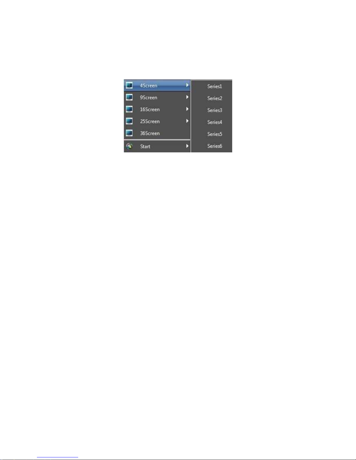
14. Image Setting
Adjust the video image brightness/sharpness/ Saturation/ tone volume on the "Image
Setting" interface, as shown in the below picture:
Page 42
42
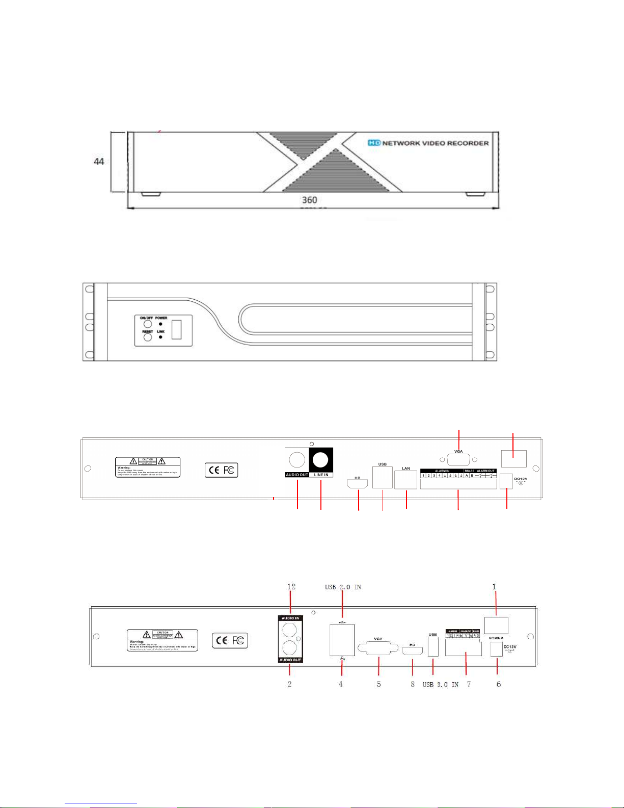
15.Screen Aspect Ratio/Segmentation
According to the NVR version there are 4 screen/9 screen/ 16 screen/ 25 screen/ 36 screen
for selection.
Page 43
43
Description of the front and rear panel of the NVR
Front Panel art. IPNVR109A, IPNVR116A, IPNVR116B and IPNVR116C
Front Panel art. IPNVR125A
Rear Panel art. IPNVR109A and IPNVR116A
Rear Panel art. IPNVR116B and IPNVR116C
1 2 3 8 9 4 7 6
Power switch
5
Power switch
Page 44
44
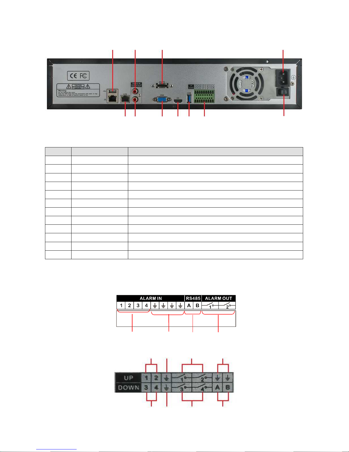
Rear Panel art. IPNVR125A
The rear panel of port function is shown as follow:
Item No.
Parameter
Description
1 Connector Main input port (230 VCA)
2 Audio output Audio signal output port
3 Talk back Audio input for talk back
4 Network port RJ-45 Network port
5 VGA port VGA video signal output port
6 Power supply input Power supply input port (12 VDC)
7 Connecting terminal Include alarm input, alarm output,RS-485 port
8 HD port HDMI Video signal output port
9 USB To connect USB mouse, Mobile HDD,USB Storage drive, etc.
10 ESATA port ESATA HDD port
11 USB 3.0 USB port
12 Audio input Audio signal input port
Rear panel I/O port connection
1 2 4 3
Power switch
1 2 3 2
1 2 3 4
Page 45

45
Rear panel I/O port function is shown as follow:
Item No.
Parameter
Description
1 Alarm input Alarm input port, connected to the alarm
2 GND Ground port
3 Alarm output Alarm output port
4 RS-485 RS-485 output port, connected to the PTZ
Description of the front and rear panel of the PoE NVR
Front Panel art. IPNVR104APOE and IPNVR104BPOE
USB
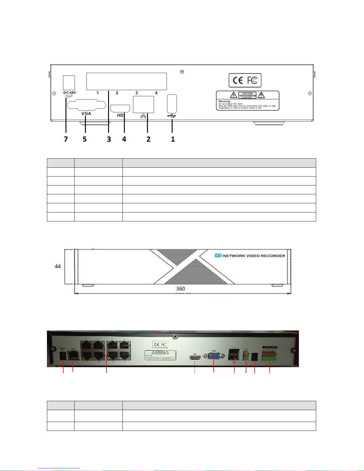
Rear panel art. IPNVR104APOE
The rear panel of port function is shown as follow:
Item No.
Parameter
Description
1 USB
To connect USB mouse, Mobile HDD,USB Storage drive, etc.
2 Network port 10/100/1000 Mbit/sec. RJ-45 Network port
3 PoE network ports RJ-45 Network port with PoE power supply to connect the cameras
4 HD port HDMI Video signal output port
5 VGA port VGA video signal output port
6
Connecting
terminals
RS-485 port
7
Power supply input
Power supply input port (48 VDC)
Page 46
46
Rear panel art. IPNVR104BPOE
The rear panel of port function is shown as follow:
Item No.
Parameter
Description
1 USB
To connect USB mouse, Mobile HDD,USB Storage drive, etc.
2 Network port 10/100/1000 Mbit/sec. RJ-45 Network port
3 PoE network ports RJ-45 Network port with PoE power supply to connect the cameras
4 HD port HDMI Video signal output port
5 VGA port VGA video signal output port
7
Power supply input
Power supply input port (48 VDC)
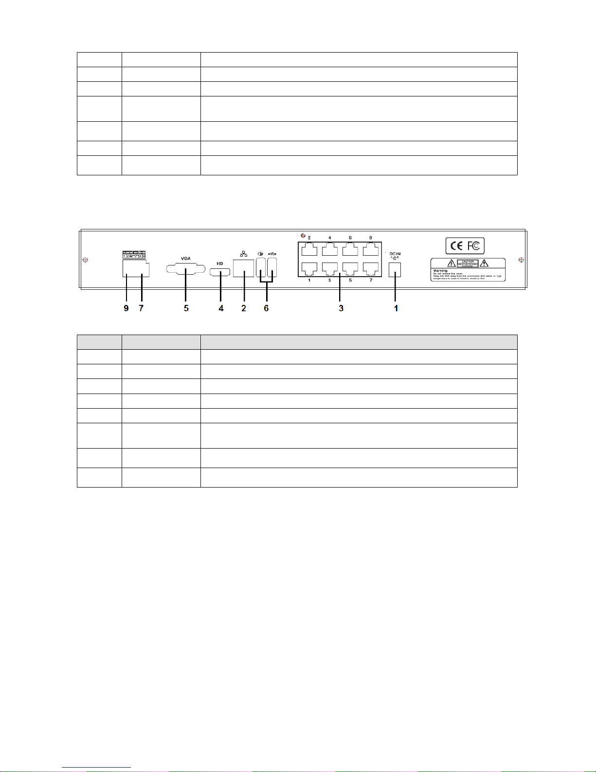
Front Panel art. IPNVR108APOE and IPNVR108BPOE
Rear panel art. IPNVR108APOE
The rear panel of port function is shown as follow:
Item No.
Parameter
Description
1
PoE Power supply
input
PoE Power supply input port (48 VDC)
2 Network port 10/100/1000 Mbit/sec. RJ-45 Network port
1 2 3 4 5 6 7 8 9
Page 47
47
3 PoE network ports RJ-45 Network port with PoE power supply to connect the cameras
4 HD port HDMI Video signal output port
5 VGA port VGA video signal output port
6 USB
To connect USB mouse, Mobile HDD,USB Storage drive, etc..
7
Connecting
terminals
RS-485 port
8
Power supply input
Power supply input port (12 VDC)
9
Connecting
terminals
To connect alarm input and alarm output
Rear panel art. IPNVR108BPOE
The rear panel of port function is shown as follow:
Item No.
Parameter
Description
1
Power supply input
Power supply input port (48 VDC)
2 Network port 10/100/1000 Mbit/sec. RJ-45 Network port
3 PoE network ports RJ-45 Network port with PoE power supply to connect the cameras
4 HD port HDMI Video signal output port
5 VGA port VGA video signal output port
6 USB
To connect USB mouse, Mobile HDD,USB Storage drive, etc..
7
Connecting
terminals
RS-485 port
9
Connecting
terminals
To connect alarm input and alarm output
NOTE: If you want to manage the NVR also via smartphone, you must correctly set on the
router, in addition to the port number in the field “Remote port”, also the following three. The
port to set on the smartphone is the third subsequent.
I.E.: if the port in the field “Remote port” is the no. 5050 (default), You must also port
forwarding on the router the ports 5051, 5052 and 5053. The port to set on the
smartphone is the 5053.
Page 48

48
COMELIT DNS SERVICE
For this series of NVR is now available the Comelit DNS service.
To use it proceed as follows:
1 – check the firmware version of the device. If necessary, update the firmware
2 – verify that on the device, nearby the label showing the model, is present the label with
the univocal code for the DNS service registration. In case it was not present, contact
Comelit Technical support
3 – connect to the site http://www.comelitdns.com , sign up by following the instructions and
then create a host using the activation code above
4 – enter the data (hostname, user and password [10 char. max) in the appropriate NVR
menu
5 – to connect to the device registered, enter http://hostname.comelitdns.com:port (if
different from 80)
 Loading...