

Page 1
1
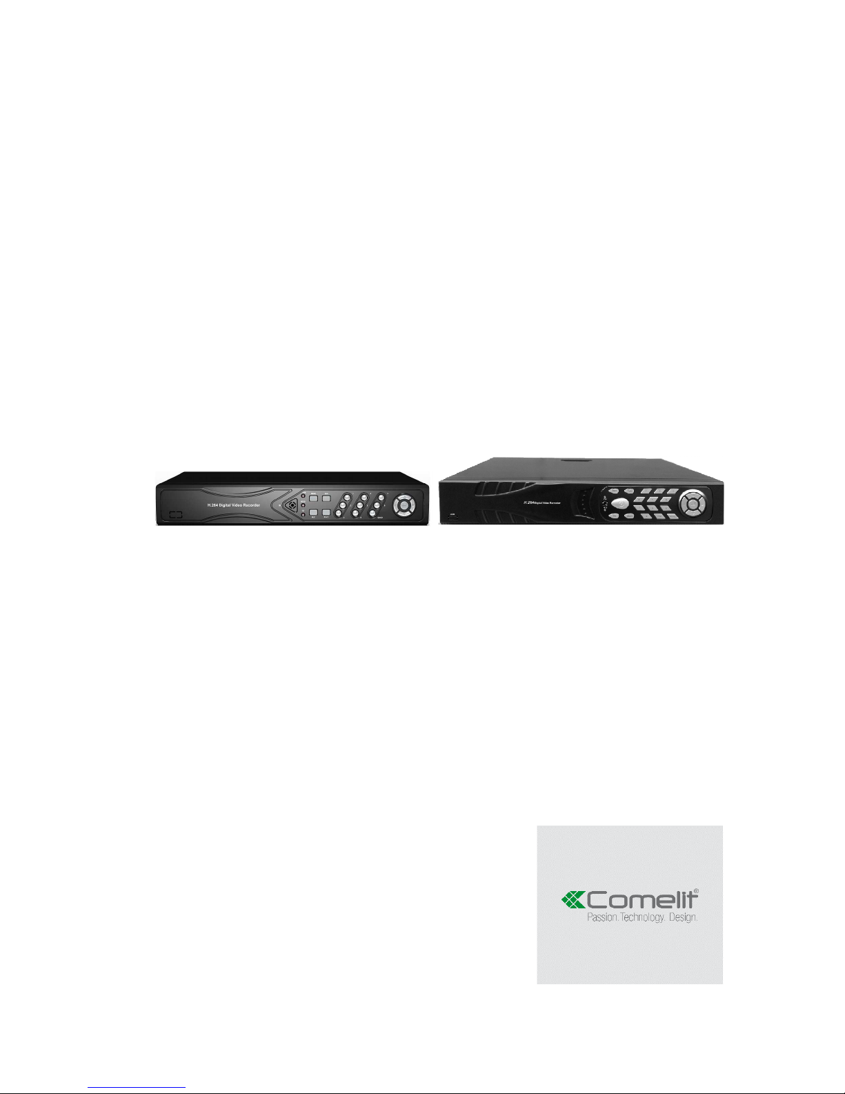
16-25-36 INPUTS H264 STAND-ALONE
NETWORK VIDEO RECORDER
ART. IPNVR006A
IPNVR025A
IPNVR036A
Please read this manual thoroughly before use and keep it for future reference
Page 2

2
Technical parameters
Model IPNVR006A-IPNVR025A-IPNVR036A
Operation Embedded Linux operation system
Operation system Graphical user interface (GUI), mouse, front button, remote control
Imagine compression H.264
Recording mode Manual, Scheduled, Event
Video Search Time, Event, Channel, Log
Backup Network, USB
Video input RJ45
Video output VGA, HDMI
Motion Detection
each channel can set the detection area and the multi-level
sensitivity
Image display 1/4/9/16
Video Save HDD, network
HDD interface SATA
USB Interface 2 x USB2.0
Power 100-240 VAC / 50-60 Hz
Page 3
3
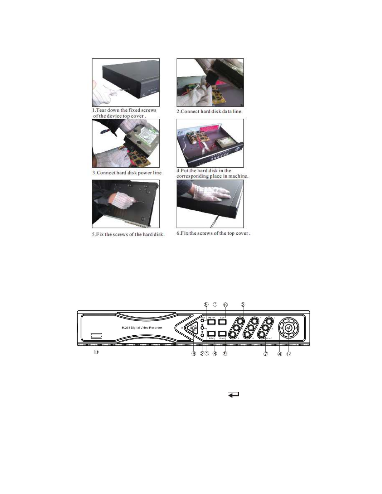
HDD Installation
Make sure to install the HDD when You first use it.
.
Front Panel Description
1. HDD led 9. PLAY: Playback key
2. State led, reserved 10. ESC: Exit key
3. 1 ~ 8: CH1 ~ CH8 Single-Screen keys 11. MENU: Menu key
4. ▲▼◄►: Direction key 12. : Confirm key
5. POWER led 13. N.C.
6. IR receiver
7. QUAD key
8. REC: Manual recording key
IPNVR006A front panel
Page 4
4
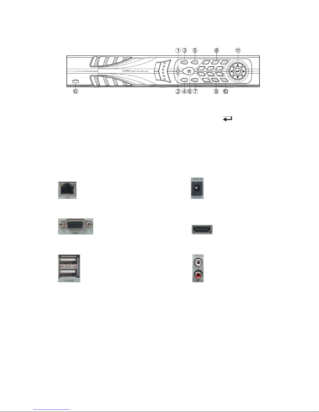
1. POWER led 9. ESC: Exit key
2. HDD led 10. MENU: Menu key
3. REC: Manual recording key 11. ▲▼◄►: Direction key, : Confirm key
4. FN key 12. N.C.
5. PLAY: Playback key
6. ON/OFF key
7. Multi-Screen key
8. Single-Screen keys
Rear Panel Description
NET: 10/100/1000 Mbit/sec. standard Ethernet port DC12V: 12 VDC power supply connector
VGA: VGA video output connector HDMI video output
USB: 2 x USB connectors Audio IN/Audio out: audio input/output connectors
Operating System Description
Turn ON / OFF
Confirm that AC voltage matches with NVR .Ensure that the NVR power outlet connect with a good
middle ground grounding. After switching power, the device started, 【POWER】 light is on. Turn into
system, if the panel status light flashing ,it's normal conditions.
Preview
After device start, preview interface can be seen immediately. In the preview interface you can see
IPNVR025A-IPNVR036A front panel
Page 5

5
the system date, time, channel name. Press corresponding number key of panel or click the left
mouse button, user can preview the single channel; Press "QUAD" key in the panel or click the left
mouse button, you can return to a multi-interface monitoring state.
Menu operation instructions
Menu
【MENU】,enter the device's main menu interface. 【PLAY】 shortcut keys for playback interface.
【REC】shortcut keys for manual recording.【PTZ】shortcut keys for PTZ control.
Note: default username is admin, default password is empty.
Menu composition
Menu component units as following:
(1)Check box: two kinds of status available, "√" means enabled, "□" means disabled; direction key:
【↑】【↓】【←】【--->】; enter key【 】. Also, click the left mouse button to choose.
For example: "channel" and "video mode" check box in the video research.
(2)Selection box: select the target content according to the drop-down box options. Use 【↑】, 【↓】
key or click the left mouse button to select.
For example: "channel" and "code stream" in the encode setup menu
(3)List Box: displays the research information in the list, you can try one option for operation
For example: press【 】 button in the video backup file. or the left mouse button.
(4)Edit box: enter the name into edit box
For example: in the setup menu, you could input numbers, English letters, punctuation and so on in
the "channel" edit box.
a) use panel key 【↑】【↓】【←】, 【→】or move the mouse to edit box , press " " key or click
the left mouse button, then enter keyboard appears, select the desired input target characters
through the arrow keys or click the left mouse button.
b) after input the information, click 【OK】【CANCEL】 button or button【ESC】can safe or exit
(5) button: used to implement a specific function or enter the next setup menu, click【OK /
key and the left mouse button.
ESC MENU
Press 【MENU】, 【ESC】 or the right mouse button to exit the menu mode
Click the right mouse button and return to the previous menu level.
Main Menu Introduction
Press MENU key or right mouse, it will pop-up the main menu. Main menu consists of the following
components:
Page 6
6
Split screen: select corresponding preview mode in the menu column.
Shortcut menu: in menu column, there are: Video Manage, System setup, Video playback, Video
backup, Color adjust, PTZ control, Manual record, Volume, Setup Wizard, System
mode, Fast network, Exit system. User could enter the corresponding menu preview
mode.
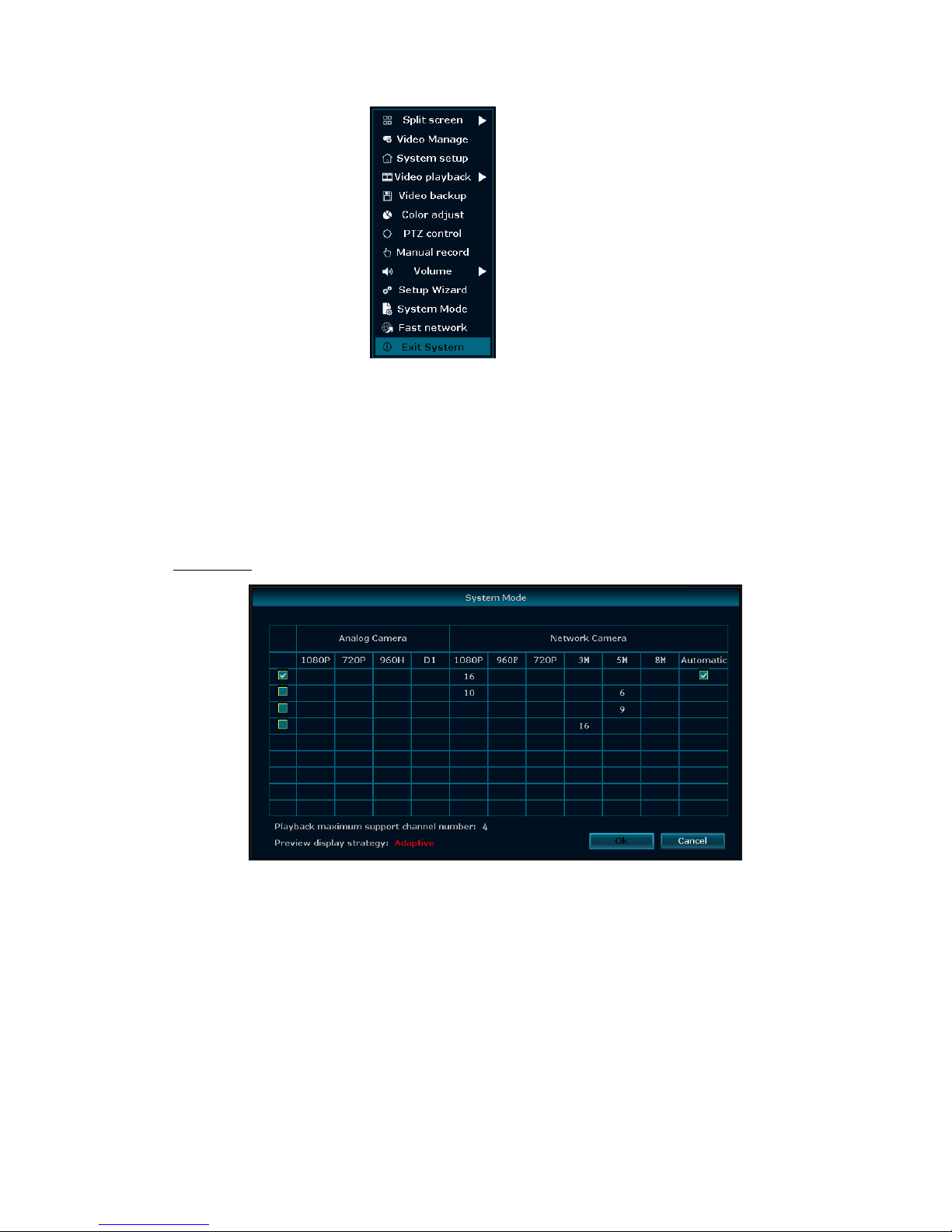
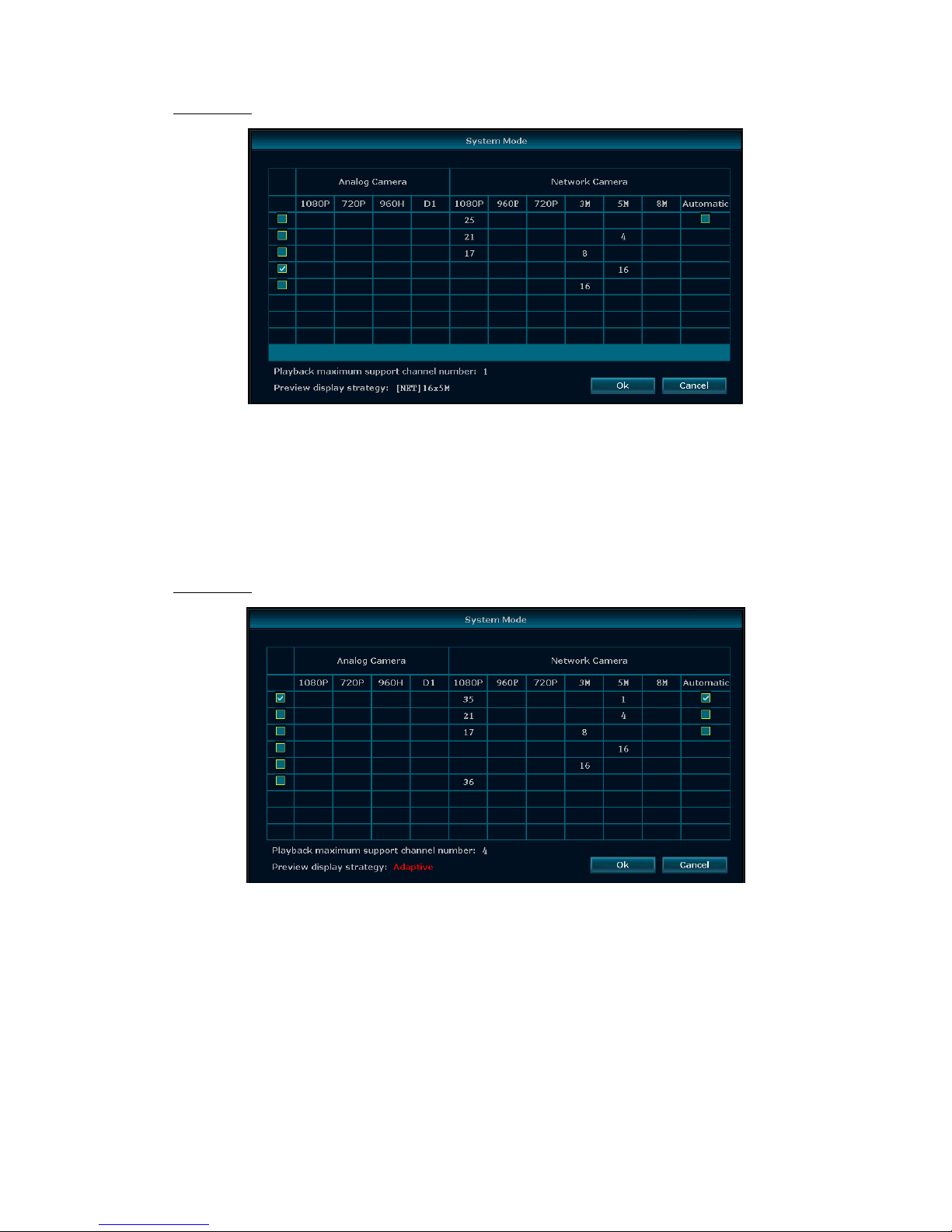
System mode
In the shortcut menu, click "System Mode", the following screen appears:
IPNVR006A
You can choose between 4 different modes:
A - 16 channels 1080p mode (720p, 960p and 1080p cameras).
B – 16 channels hybrid mode (10 cameras 720p, 960p, 1080p and 6 cameras 3MP, 4MP, 5MP).
C – 6 channels 5MP mode (720p, 960p, 1080p, 3MP, 4MP, 5MP cameras)
D – 16 channels 3MP mode (720p, 960p, 1080p and 3MP cameras)
Page 7
7
IPNVR025A
You can choose between 5 different modes:
A - 25 channels 1080p mode (720p, 960p and 1080p cameras).
B - hybrid mode 25 channels-1 (21 cameras 720p, 960p, 1080p and 4 cameras 3MP, 4MP, 5MP).
C - hybrid mode 25 channels-2 (17 cameras 720p, 960p, 1080p and 8 cameras 3MP)
D – 16 channels 5MP mode (720p, 960p, 1080p, 3MP, 4MP and 5MP cameras)
E – 16 channels 3MP mode (720p, 960p, 1080p and 3MP cameras)
IPNVR036A
You can choose between 6 different modes:
A - hybrid mode 36 channels (35 cameras 720p, 960p, 1080p and 1 camera 3MP, 4MP, 5MP).
B - hybrid mode 25 channels-1 (21 cameras 720p, 960p, 1080p and 4 cameras 3MP, 4MP, 5MP).
C - hybrid mode 25 channels-2 (17 cameras 720p, 960p, 1080p and 8 cameras 3MP).
D – 16 channels 5MP mode (720p, 960p, 1080p, 3MP, 4MP and 5MP cameras)
E – 16 channels 3MP mode (720p, 960p, 1080p and 3MP cameras)
F – 36 channels 1080p mode (720p, 960p and 1080p cameras).
The cameras 3MP/4MP/5MP must be registered mandatory on the first channels!
Page 8
8
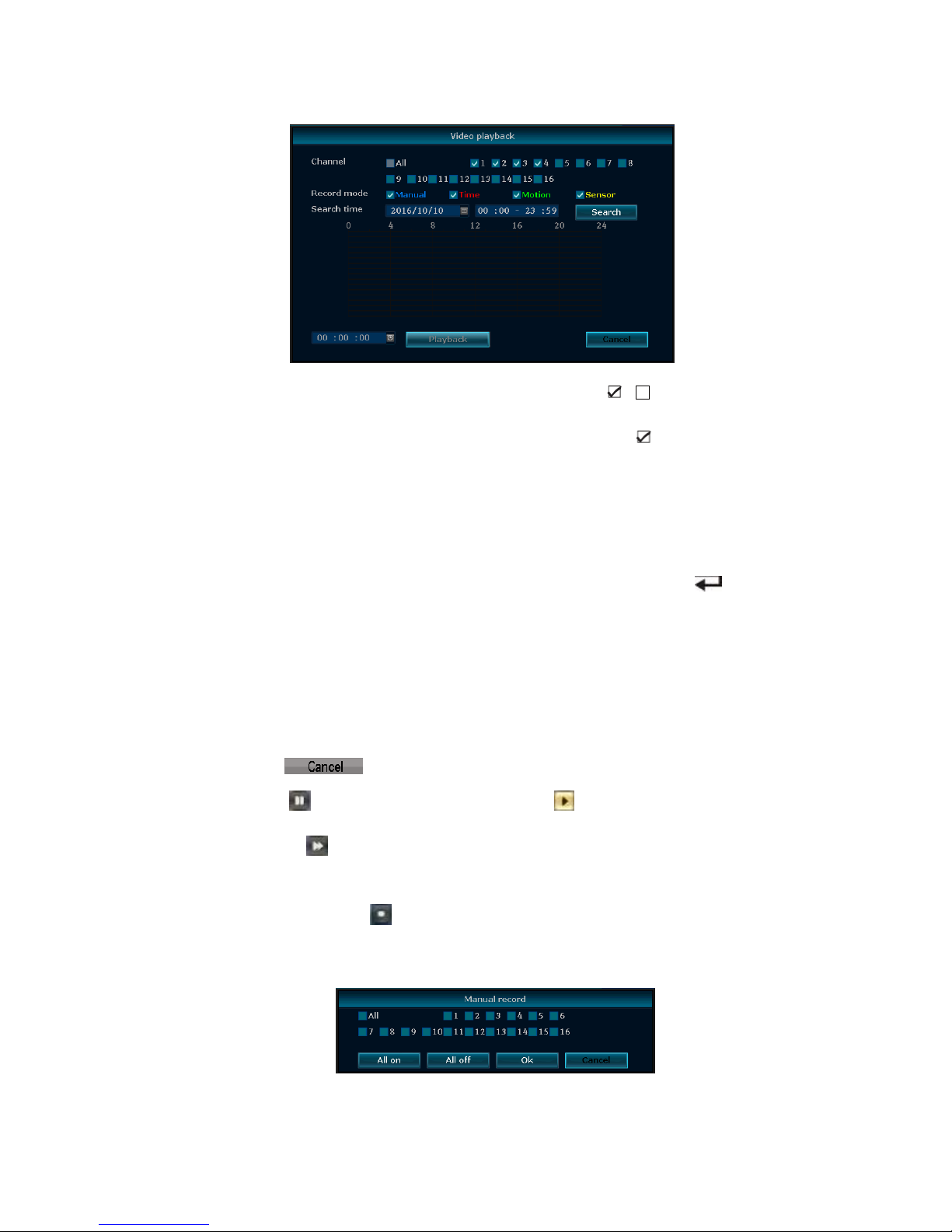
Video Playback
Channel:to choose the target channel by clicking the check box means non-selected.
Record mode:to choose the recode mode by clicking the check box
Search time:input the starting and finishing time into edit box.
Search:after setup the above search condition, click "search" to begin the corresponding video file
searching and show the files. Red means time recording, green means MD recording,
yellow means sensor recording.
Playback: chose playback and turn into playback interface. In the search list box, choose the time
bucket according up, down, left, right key or move the mouse. Click 【 】or left mouse
to enter "video playback" interface
Cancel:back to previous menu
Playback toolbar
Select the playback file or time playback file, it will turn into video playback interface.
Playback toolbar: it will show below the playback interface. Each channel can magnify or narrow by
clicking the left mouse.
Stop play:click to stop the video and turn back to playback interface.
Pause/play: click can pause the playback video, click can continue the playback video.
Fast forward:click can fast-forward the video, also times fast forward the video by click the
button again.
Exit playback:click “ESC” or can exit the playback video; or exit until all file have been played.
Manual Record
In the shortcut menu, click Manual record or click 【REC】 to enter the setup the manual record
interface.
Page 9
9
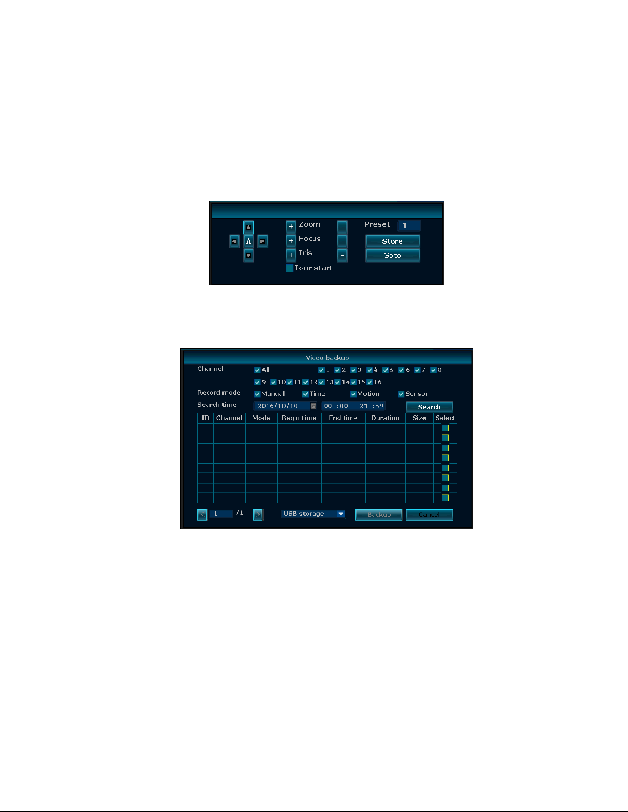
Manual record menu include several parts:
Channel: ☑”means enable; “□”means disable.
All on: enable all the channel.
All off: disable all the channel.
OK: confirm an exit
Cancel: click cancel can exit the manual record interface and back to main menu.
PTZ control
Choose the "PTZ control" from shortcut menu .
PTZ control menu including: direction control; auto pan scan; zoom; focus; Iris; speed.
Video back up
Choose the channel, and record mode; setup the search time, then begin search the file. After
choosing the needed file from list box, click Backup and Ok, wait for process bar until 100% and
show backup success.
Notes:USB driver pen must be FAT32 format when backup the file
Page 10
10
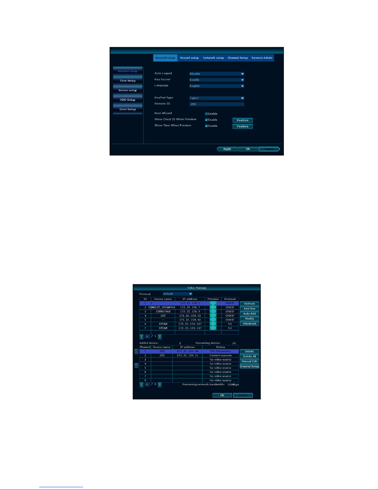
General setup
Choose the "General setup" and turn into it's setup interface.
Time Setup
:
the real time when preview, click ”Refresh” after setting, make sure saving when it
shows ”the recording will stop once you modify the time” and save the setting.
Auto Logout: the present user will be logged off if there is no operation within 10 minutes, and it
needs login again.
Key Buzzer:enabled, there is sound with the controller or pressing key on front panel. Disabled,
without sound.
Language:there is multiple choices according to users, English and so on.
Remote ID:user can use this ID to control the NVR by remote controller. The remote controller
should be correspond with the ID so that it can work.
After setting finished, click "Ok", the information will be saved. Click "Cancel" to exit without saving.
Video manage
Before connecting and set up IPC, please confirm that IPC is already connected to LAN.
Right click on the preview interface, pop-up shortcut interface, click “Video manage".
Add one: add the selected camera
Auto Add: add all cameras detected
Delete: delete the selected connected IPC
Page 11
11
Delete All: delete all the connected IPC
Manual Edit: modify the IPC parameters of the selected IPC
After finish setup, click “ Ok” button, it will be saved; click: “Cancel” button, it will be not save
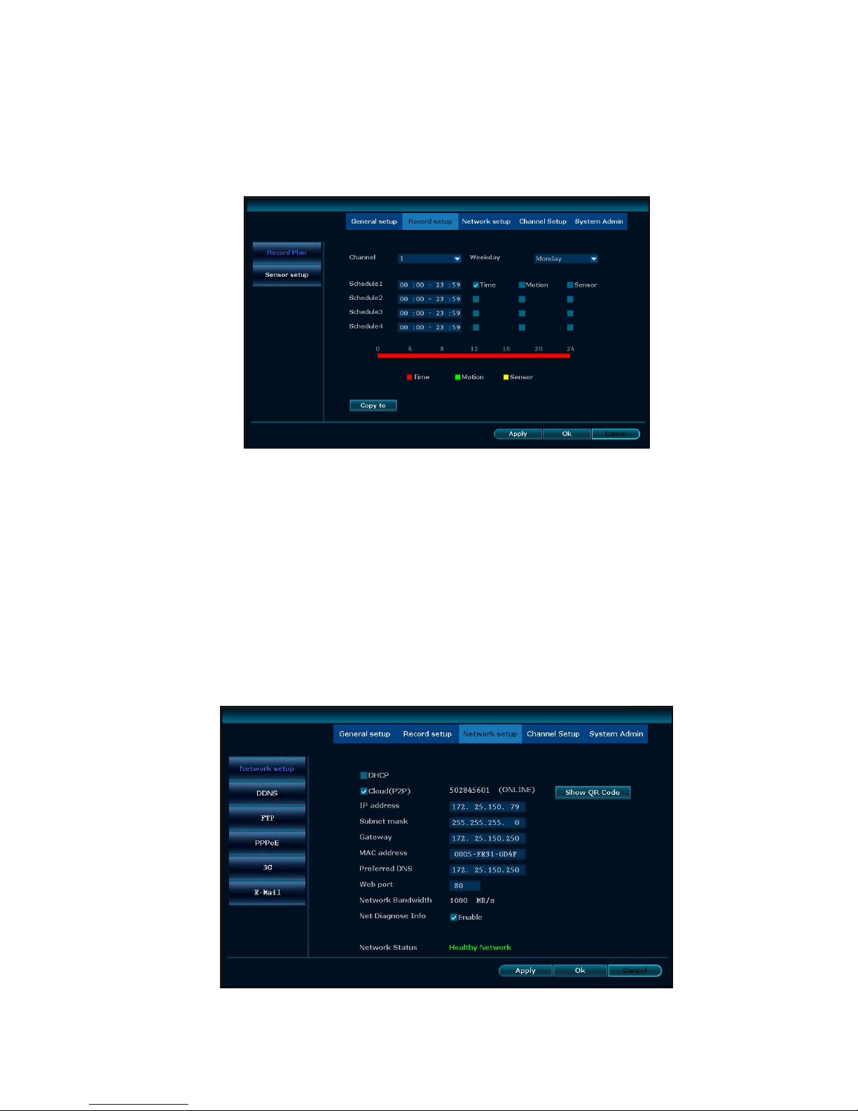
Record Setup
Select “Record setup”.
Channel:chose the channels as needed by clicking the inverted triangle
Weekday: chose the day as needed, "ALL" means all days in a week.
Schedule: every time slot can set different recording modes in all 4 time slot. "Time" recording with
red color, "Motion" recording with green color, "Sensor" recording with yellow color; “☑" means
enabled, “□” means disabled. The bottom parts has times status display, whole schedule from time
0~24 hours
Copy to: select the target channel on the right of "copy to "button, click "copy to" and ''Ok" to set
the current channel setup informations to other target video channel. By clicking the button "Cancel",
the setup informations are non-saved.
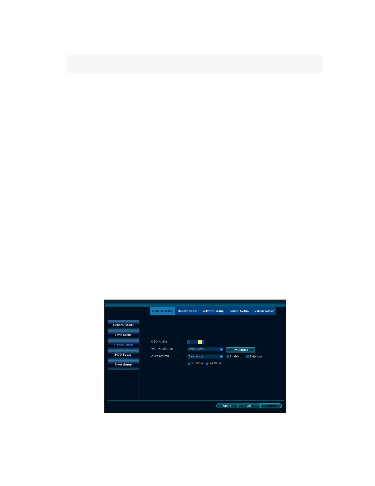
Network setup
Page 12
12
Select “network setup”.
DHCP: choose to enable to obtain IP address automatically. "☑" means enabled ,"□" means
disabled
Cloud (P2P):after connecting internet , click“☑ Cloud (P2P)” to gain a ID , which can be used in IP
remote monitoring in ESeenet network server
IP address:the IP address must be unique and cannot be in conflict with the host or workstation on
the same network segment
Subnet mask:subnet for the network segment.
Gateway: need to set the gateway address to achieve communication between the different
network segments.
MAC address:showing the device's MAC address
Preferred DNS:DNS IP address
Web port:port number IE browser visit, default port is "80"
PPPOE
Start using:“☑ PPPOE” means to start up PPPOE dial-up. “□” means not to start up
Username:input the user name of ISP into edit box
Password:input the password of ISP into edit box
After the page setup is completed, click '"Ok" to save the changes; click "Cancel ", non-save.
DDNS
Automatic analytical function of dynamic domain name, supported Comelit DNS, etc. To use Comelit
DNS see the last page of this manual.
In the "network setup" menu, click " DDNS "
Start using:“☑”means DDNS dynamic domain services start using: “□”means not to start up.
Select the right network server and input user name, password and domain
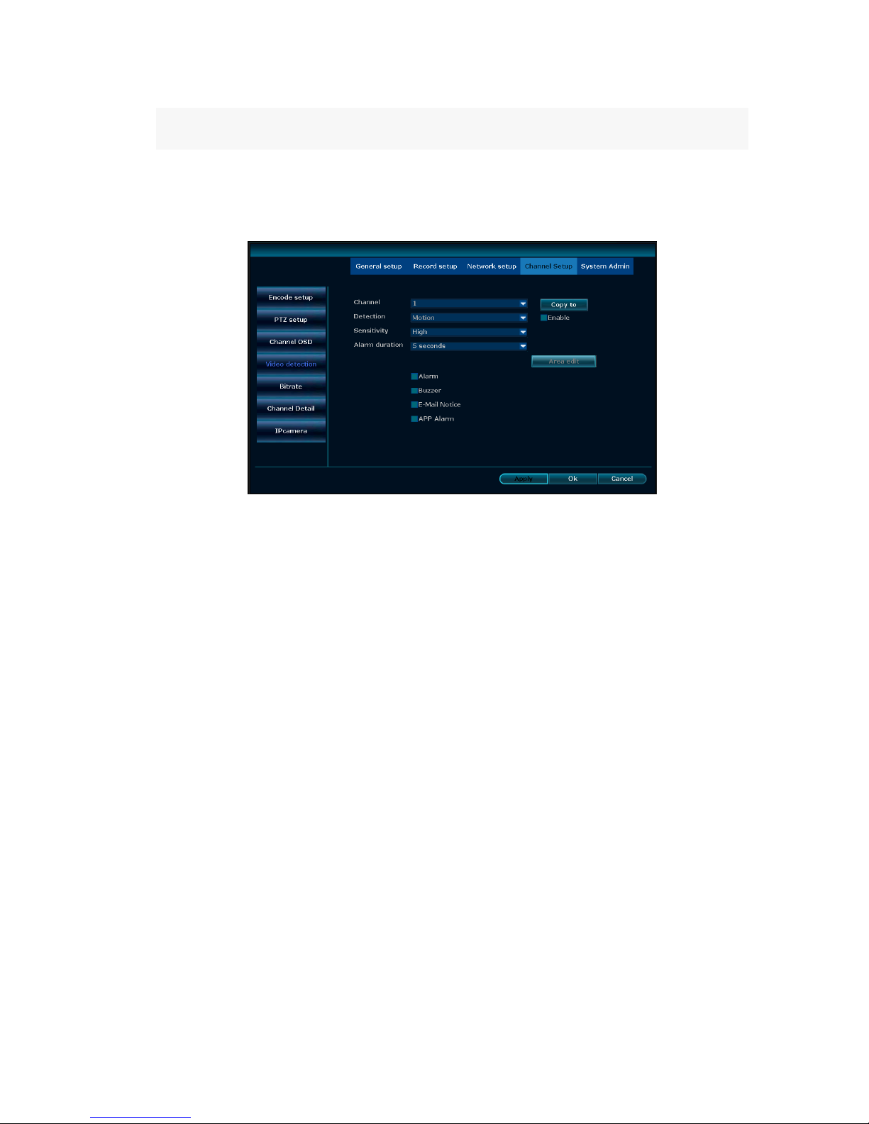
Screen Setup
Select “screen setup”
OSD Alpha
:
OSD menu transparency can be adjusted as needed.
Page 13
13
VGA Resolution:
choose the desired resolution
Auto Switch: user can setup the time of auto switching for preview image, it switch in single screen
or 4 channels screen.
Enable:“☑”start using, “□” non-start using
After the page setup is completed, click '"Ok" to save the changes ; click "Cancel ", non-save.
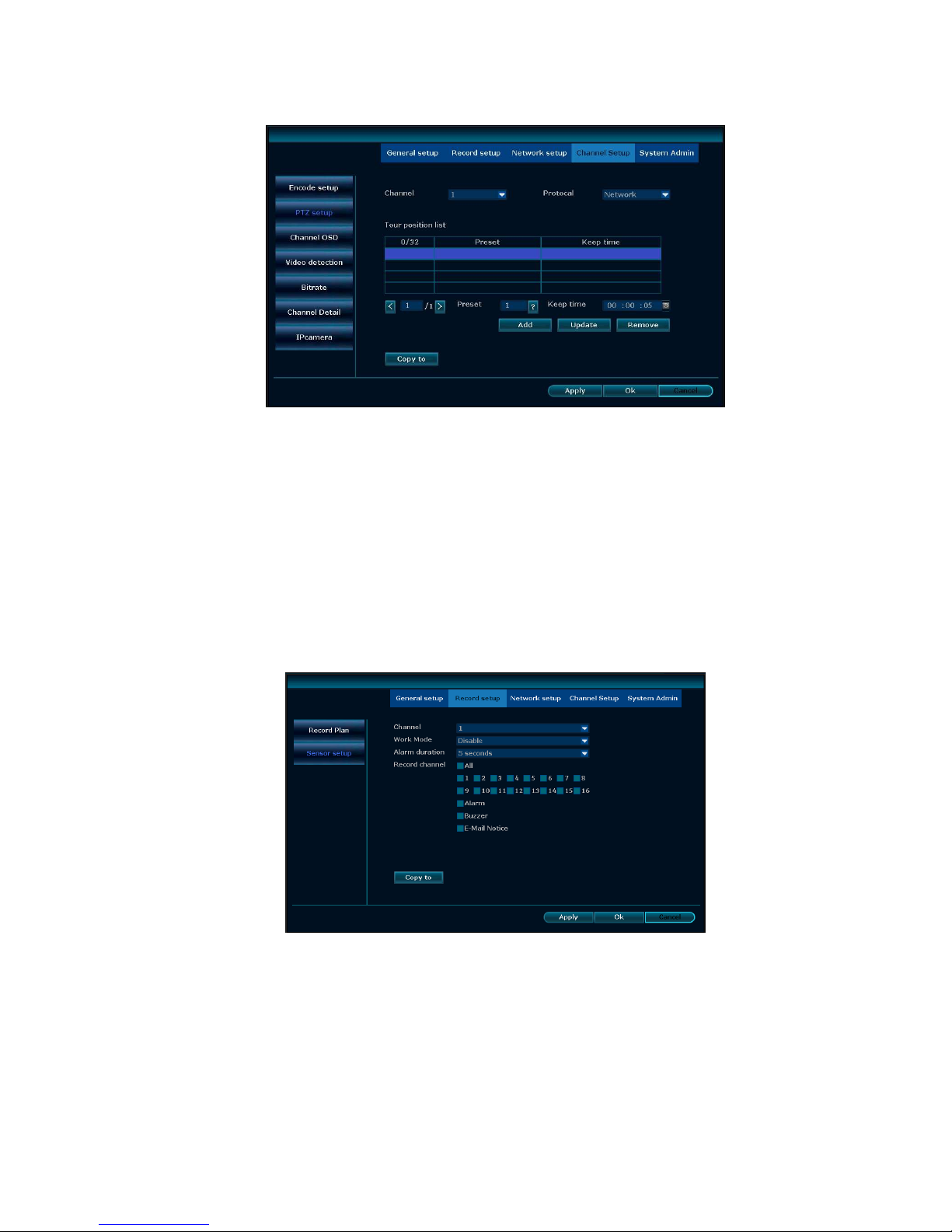
Video detection
Channel: the option to set the alarm channel selection box
Detection:select detection type motion, video loss
Sensitivity:chose the trigger video detection sensitivity
Alarm duration: after chose the trigger video detection, choose the time alarm.
Area edit : setup motion detection area; move by dragging the left of mouse.
Alarm:“☑”means start ,“□”means non start 。
Buzzer :“☑”means start ,“□”means non start。
E-Mail notice: “☑” means sent E-Mail enabled, “□” means sent E-Mail disabled.
Copy to: click "copy to", select the target channels and ''Ok" to set the current channel setup
informations to other target video channel. By clicking the button "Cancel", the setup
informations are non-saved.
Page 14
14
PTZ Setup
Select ”PTZ setup”
Select ”PTZ setup”
Channel: choose the right channel, click the select box to choose
Protocol: the selected protocol must be the same with the one of PTZ
Copy to: click "copy to", select the target channels and ''Ok" to set the current channel setup
informations to other target video channel. By clicking the button "Cancel", the setup informations
are non-saved.
After the setting, click the button of sure to exit with saving the setting, or click the button Cancel to
exit without saving.
Sensor setup
Select "Sensor setup".
Channel: choose the right channel, click the select box to choose
Work mode: setting to start alarm or not
Alarm duration: set up alarm duration time
Record channel: when alarm is triggered, channel needed to be recorded
Alarm: “☑” enable alarm, “□” close alarm
Buzzer: “☑”start buzzer, “□” close buzzer
Page 15
15
Copy to:click "copy to", select the target channels and ''Ok" to set the current channel setup
informations to other target video channel. By clicking the button "Cancel", the setup informations
are non-saved.
After the setting, click "OK" to exit with saving or click "Cancel" to exit without saving.
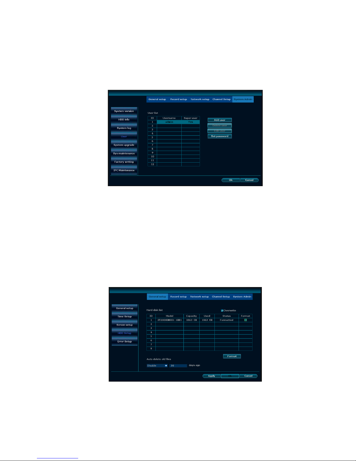
User management
Select "User".
Add user: input a new user name in the edit box and set up the operational authority. Click the "Set
Password" to set the new password or it can be the default password.
Delete user: delete the selected user (except Admin, other user has no the right to set up or delete
other users)
Edit user: modify the selected user (Admin, other users has no right to set up other user
permissions)
Set password: set password of logging in user
After the setting, click "OK" to save and exit, or click "cancel" to exit without saving
HDD setup
Select "HDD setup".
Overwrite: “☑” earliest recording files will be covered when the disk is full, “□"shows not cover.
Format: “☑” stands selected, “□” stands not selected, when click "Format" a confirm interface will
pop up, then click confirm to format, click cancel to return the main interface.
Page 16
16
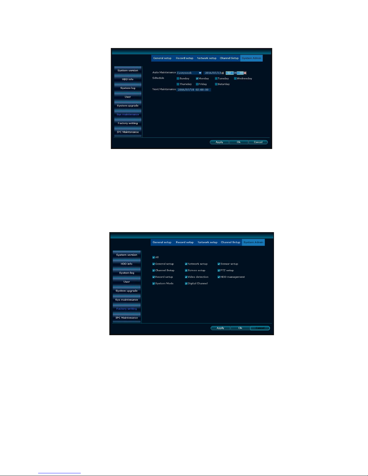
System maintenance
Select "System maintenance".
Auto reboot: setting automatic reboot time, it can set" Saturday to Sunday", "Never" means do not
reboot automatically.
System upgrade
: copy firmware to the root directory of USB drive, insert USB, select the USB
storage device, then click "start" to upgrade. When upgrade is completed, click "Ok" then system
auto reboot.
Note: during upgrade, do not cut off power to protect from device damage
Factory setting
Select "Factory setting".
Select the items which need factory setting, click "Ok" to save and exit or click "Cancel" to exit
without saving.
Notes: after factory setting, all the settings will be the initial one, please use carefully.
Page 17
17
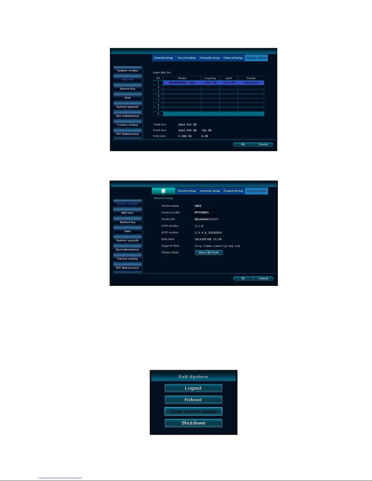
HDD info
The listbox shows the HDD status information
System version
Device name ,device model, H/W version, S/W version could be checked here.
System log
Choose the log type which need to check from list box, and input the time period in the edit box, then
click "Search", the related log information will showed below, you can turn the page by click
"previous" and "next" or input target page to turn
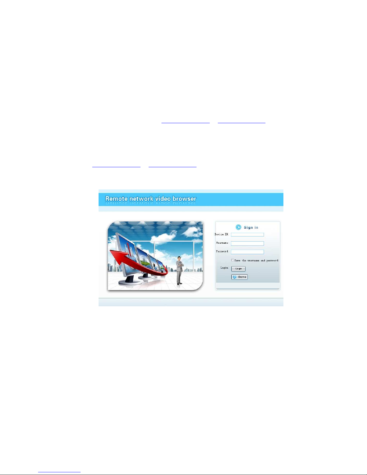
System logout
In the main menu, click "System logout", popup setting interface
Page 18
18
Logout: apply for logging users. After logout, if you want to use the device again, need to login
again
Reboot: it will reboot after "OK".
Shutdown: shutdown the NVR
Esee User Manual
1. Connect DVR with network, make sure network working fine
2. For remote view in computer, go to www.dvrskype.com or www.e-seenet.com
Do the following setup before you log in Esee on computer
Note: Internet Explorer setting. If use it for the first time and the software can't load, then
need to make the following setting: Internet options Safety-Internet Custom options
pick Active X and plugin all for opening, click ok.
1. Go to www.dvrskype.com or www.e-seenet.com,input Esee ID, user name and password, this
user name and password is same with DVR user name and password
Note: the default user name is admin, no password
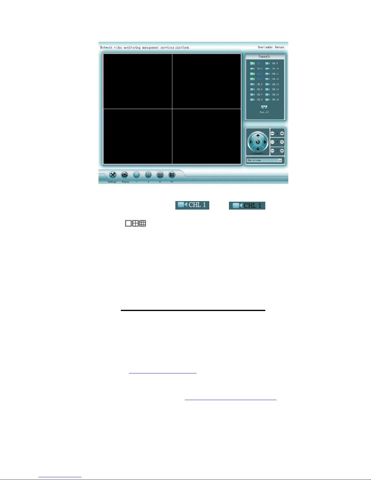
Video monitoring homepage:
Monitoring homepage including: preview window, PTZ control, preview, stream selection, channel
opening, setting, playback, user logout, as below:
Page 19
19
Open preview:click the target channel with mouse left. Double click the channel can open or close
the correspond preview channel, such as: open; close.
Preview mode: click to choose the mode or double click preview window to switchover
into multi-channel mode
NOTE: to view images of NVRs art. IPNVR006A, IPNVR025A and IPNVR036A from
smartphones (iOS or Android OS) please use the app "Comelit View S" which is freely
downloadable from the relative stores (Apple Store and Google Play). The same app for
smartphones has to be used for tablet devices.
COMELIT DNS SERVICE
For this series of NVR is now available the Comelit DNS service.
To use
it
proceed as follows:
1 – check the firmware version of the device. If necessary, update the firmware
2 – verify that, on the device, nearby
the
label showing the model, is present the label with the
univocal code for the
DNS
service registration. In case it was not present, contact Comelit
Technical support
3 – connect to the site http://www.comelitdns.com, sign up by following the instructions and then
create a host using the activation code above
4 – enter the data (hostname, user and password) in the appropriate NVR menu
5 – to connect to the device registered, enter http://hostname.comelitdns.com:port (if different from
80)
Page 20

20
 Loading...