

Page 1
EN
TECHNICAL
MANUAL
www.comelitgroup.com
VEDO system - Technical Manual
Page 2

2
SOMMARIO
General introduction ..........................................................................................................................................................................................4
Introduction to the system ................................................................................................................................................................................4
Description of system components ...........................................................................................................................................................................................4
Communication standard ........................................................................................................................................................................................................4
Module addresses ...................................................................................................................................................................................................................4
General information .....................................................................................................................................................................................................................5
Main system specifi cations: ....................................................................................................................................................................................................5
Housings .......................................................................................................................................................................................................................................6
Fitting and wiring the switchboard .............................................................................................................................................................................................6
Fitting the housing and anti-tear tamper .................................................................................................................................................................................8
Switchboard card (30001008 - 30001034 - 30001068) ...............................................................................................................................................................9
Main features ..........................................................................................................................................................................................................................9
Identifi cation of connections to switchboard terminals ....................................................................................................................................................9
Confi guration jumpers .....................................................................................................................................................................................................10
Power supply connection .................................................................................................................................................................................................10
Terminal block M1 ............................................................................................................................................................................................................10
Terminal block M2 ............................................................................................................................................................................................................10
Terminal block M3 ............................................................................................................................................................................................................10
Indicator lights .................................................................................................................................................................................................................10
Module connectors ..........................................................................................................................................................................................................10
Internal expansions .....................................................................................................................................................................................................................11
Telephone dialler functions (PSTN as standard) .............................................................................................................................................................11
Messages and Voice Control expansion module (art. 30001303) ..........................................................................................................................................11
Audio module functions ...................................................................................................................................................................................................11
Fitting the messages and voice control expansion module .............................................................................................................................................11
GSM communication expansion module (art. 30001301) .......................................................................................................................................................12
Fitting the GSM module ...................................................................................................................................................................................................12
GSM telephone dialler: antenna, SIM card and indicator lights ..............................................................................................................................................13
Connecting the antenna ..................................................................................................................................................................................................13
Locating the antenna remotely ........................................................................................................................................................................................13
Fitting the SIM card .........................................................................................................................................................................................................13
Meaning of the LEDs on the IP GSM module ..................................................................................................................................................................13
TCP/IP Ethernet expansion module (art. 30002401) ..............................................................................................................................................................13
IP network communication module .........................................................................................................................................................................................14
Plugging in and unplugging the MicroSD memory card ..................................................................................................................................................14
Meaning of the LEDs on the IP module ...........................................................................................................................................................................14
General information about connecting devices to the bus ......................................................................................................................................................15
Bus line termination: ..............................................................................................................................................................................................................15
Wiring the inputs ..........................................................................................................................................................................................................................15
Single balanced ......................................................................................................................................................................................................................16
Double balanced .....................................................................................................................................................................................................................16
Triple balanced .......................................................................................................................................................................................................................16
Double zone ............................................................................................................................................................................................................................16
Double zone with end of line (EOL double) ............................................................................................................................................................................16
Wiring the switchboard's 24-hour input .....................................................................................................................................................................................17
PSTN telephone dialler ...........................................................................................................................................................................................................17
Main control and display components .......................................................................................................................................................................................17
LCD keypad (art. 30006002) ...................................................................................................................................................................................................17
Main features: ................................................................................................................
..................................................................................................17
Meaning of LEDs .............................................................................................................................................................................................................17
DIP switches and bus termination ...................................................................................................................................................................................17
LCD keypad terminal block description ...........................................................................................................................................................................17
LCD keypad with RFID key reader (art. 30006003) ................................................................................................................................................................18
Meaning of LEDs .............................................................................................................................................................................................................18
Mounting and wiring the keypads ...........................................................................................................................................................................................18
RFID proximity reader on bus (art. 30006104) .......................................................................................................................................................................19
Main features: ..................................................................................................................................................................................................................19
Meaning of LEDs .............................................................................................................................................................................................................19
Setting RFID reader speed ..............................................................................................................................................................................................20
Addressing DIP and bus termination ..............................................................................................................................................................................20
485 line termination .........................................................................................................................................................................................................20
RFID key reader on bus terminal block description .........................................................................................................................................................20
Mounting the RFID key reader on bus ....................................................................................................................................................................................20
RFID keys (art. SK9050x/A) ....................................................................................................................................................................................................20
Other devices that can be connected to the 485 bus ...............................................................................................................................................................21
Safetouch (art. 30006001) / Minitouch (art. 20034607) with RFID key reader .......................................................................................................................21
Main features: ..................................................................................................................................................................................................................21
485 line termination .........................................................................................................................................................................................................21
Safetouch/Minitouch terminal block description ..............................................................................................................................................................21
Addressing and speed confi guration of Safetouch/Minitouch bus ...................................................................................................................................21
Planux Manager with RFID key reader (art. 20034801) .........................................................................................................................................................22
Planux Manager terminal block description .....................................................................................................................................................................22
485 line termination .........................................................................................................................................................................................................22
Addressing and speed confi guration of Planux Manager bus .........................................................................................................................................22
Warnings
• Install the equipment by carefully following the instructions given by the manufacturer and in compliance with the standards in force.
• All the equipment must only be used for the purpose it was designed for. Comelit Group S.p.A. declines any responsibility for improper use of the apparatus, for any alterations made by others
for any reason or for the use of non-original accessories or materials.
• All the products comply with the requirements of Directive 2006/95/EC, as certifi ed by the CE mark they carry.
• Installation, mounting and assistance procedures for electrical devices must only be performed by specialised electricians.
• The electrical system of the building must be fi tted with an omnipolar mains switch with a contact opening of at least , which is capable of isolating the power supply of the device.
• Cut off the power supply before carrying out any maintenance work.
• Place the protection back over the terminals and close the inspection door after every procedure.
• The device conforms to standard EN60950-1 relating to the safety of information technology equipment.
Page 3

3
Guidance on the installation of Safetouch, Minitouch and Planux Manager .........................................................................................................................22
Safetouch/Minitouch ...............................................................................................................................................................................................................22
Planux Manager ......................................................................................................................................................................................................................22
Expansions on 485 bus ...............................................................................................................................................................................................................22
Expansion on bus with 8 balanceable inputs and 8 logic outputs on bus (art. 30003101) .....................................................................................................22
Fitting the expansions in a small external housing .................................................................................................................................................................23
Main features ...................................................................................................................................................................................................................24
Confi guration jumpers description ...................................................................................................................................................................................24
Correlation table: position of DIP switches SW1, device n° and bus speed ....................................................................................................................24
Input/output expansion module terminal block description ..............................................................................................................................................24
Bidirectional radio expansion on bus (art. 30003201).............................................................................................................................................................25
Main features ...................................................................................................................................................................................................................25
Confi guration jumpers description ...................................................................................................................................................................................25
Correlation table: position of DIP switches SW1, device n° and bus speed ....................................................................................................................25
Radio expansion module terminal block description .......................................................................................................................................................25
Wireless sensors and accessories .............................................................................................................................................................................................25
Wireless connectable devices .................................................................................................................................................................................................25
Guidance on the installation of wireless sensors and sirens ..................................................................................................................................................25
PAL/IP video module art. 30001445 .......................................................................................................................................................................................26
MMS – system description and minimum requirements ..................................................................................................................................................26
Network parameters of PAL/IP module ............................................................................................................................................................................26
Outputs .........................................................................................................................................................................................................................................27
Siren connection examples .........................................................................................................................................................................................................27
Connecting a self-powered siren with 3 or 2 wires .................................................................................................................................................................27
Connecting a non-self-powered indoor siren ..........................................................................................................................................................................27
Example of connection to outputs TC1 and TC2 ......................................................................................................................................................................27
Power supply units with dynamic battery testing .....................................................................................................................................................................28
1.5A – (art. 30076101) ............................................................................................................................................................................................................28
3A – (art. 30076102) ...............................................................................................................................................................................................................28
5A – (art. 30076103) ...............................................................................................................................................................................................................28
Addressing the BUS and setting its speed via dip switch .......................................................................................................................................................30
Terminal block description ..........................................................................................................................................................................................................30
Confi guration jumpers .................................................................................................................................................................................................................30
LED signals ...................................................................................................................................................................................................................................30
PSU connector .............................................................................................................................................................................................................................30
Tamper contact connection.........................................................................................................................................................................................................30
Connecting V- reference terminal ..............................................................................................................................................................................................31
Earth connection ..........................................................................................................................................................................................................................31
Art. 30003106 technical specifi cations ......................................................................................................................................................................................31
BUS Isolator Art. 30003105 ................................................................................................................................................................................31
Addressing the BUS and setting its speed via dip switch .......................................................................................................................................................32
LED signals ...................................................................................................................................................................................................................................32
BUS isolator terminal block ........................................................................................................................................................................................................32
Tamper contact connection.........................................................................................................................................................................................................32
What to do before powering up the system ....................................................................................................................................................33
Connect the zone inputs correctly .............................................................................................................................................................................................33
Connect the bus modules ...........................................................................................................................................................................................................33
Set the addresses of the bus devices ........................................................................................................................................................................................33
Close all the anti-tamper inputs ..................................................................................................................................................................................................33
Switch on the power ....................................................................................................................................................................................................................33
Default confi guration .........................................................................................................................................................................................33
Introduction to programming from the keypad ...............................................................................................................................................33
Default codes at fi rst start-up .....................................................................................................................................................................................................33
Modifying parameters/text with the keypad ..............................................................................................................................................................................34
Setting the serial number of the keypad ....................................................................................................................................................................................35
Activating and deactivating the system .....................................................................................................................................................................................35
Muting an alarm with the system deactivated ...........................................................................................................................................................................35
Going into programming mode as a User .................................................................................................................................................................................35
Going into programming mode as an Installer (installer code authorisation) .......................................................................................................................35
Changing the date and time ........................................................................................................................................................................................................36
Acquiring an RFID key code from the keypad ...........................................................................................................................................................................36
Acquiring a radio sensor code from the keypad .......................................................................................................................................................................36
Acquiring a radio control code from the keypad ......................................................................................................................................................................37
Acquiring a siren code from the keypad ....................................................................................................................................................................................37
Exiting programming mode ........................................................................................................................................................................................................37
Restoring factory settings ...........................................................................................................................................................................................................37
Partial Reset (code recovery) ......................................................................................................................................................................................................37
Setting the control panel to Service Status ...............................................................................................................................................................................38
Exiting Service Status .................................................................................................................................................................................................................38
Switchboard electrical specifi cations ..............................................................................................................................................................38
APPENDICES ......................................................................................................................................................................................................39
Appendix 1: offi cial symbol conventions for anti-intrusion systems .....................................................................................................................................39
Appendix 2: shielded cable conductor resistance table ..........................................................................................................................................................39
Input and signal connections ..................................................................................................................................................................................................39
Power supply connections ......................................................................................................................................................................................................40
Appendix 3: data network connection cable .............................................................................................................................................................................40
Page 4

4
General introduction
Introduction to the system
VEDO is a modern, practical system capable of meeting the technical and performance requirements of modern security systems to best effect.
The switchboard allows the creation of systems that require up to 68 individually balanceable standard zones, which can be assigned to a
maximum of 8 areas.
Description of system components
The switchboard is enclosed in a compact housing, which also accommodates the power supply unit. According to system requirements, it is
possible to equip the switchboard card directly with a module for GSM communication, a messages / voice control module and a module for
communication on IP protocol.
The connectors for powering the switchboard and for the 7Ah battery are routed from the power supply unit. A dedicated compartment inside the
switchboard housing is provided for the battery.
In addition to the switchboard and PSU, the housing can also accommodate a standard input/output expansion module adjacent to the battery,
and a second module in a compartment located underneath the switchboard card. The expansion modules are connected to the bus.
The system comprises a master unit (the switchboard) and a certain number of slave units (the peripherals on the bus). Regardless of system
activation status, the switchboard's task is to query the peripheral units periodically to determine correct operation and obtain information
about system status. Each peripheral component is equipped with local intelligence, which enables it to perform a certain number of tasks
independently and, at the request of the switchboard, communicate its status and any information relating to its specifi c peripheral functions.
Communication standard
Communication between the switchboard and expansions takes place by means of a standard RS485 bus. The switchboard's standard
communication speed is set to 38400 baud.
Module addresses
The modules are all connected to the same bus, and are recognisable by their unique address. Depending on the peripheral, this address can
be confi gured by physical means (e.g. DIP switches as on the input and output expansions) or by means of a software confi guration (e.g. LCD
keypads).
√ IMPORTANT: no two components of the same type and with the same logical address must be present on the bus. For example,
there cannot be two or more keypads with the same address. Should this happen, the system will be unable to function correctly
and will generate a bus error.
Page 5

5
Main system specifi cations:
General information
The switchboard is supplied with a built-in digital dialler.
The switchboard can be programmed directly from the keypad or, more easily, by means of dedicated software. The audio messages can be
modifi ed only by using the programming software from a PC.
The association of zones to areas and partial subgroups of areas allows total, partial or selective activation of the system, according to the
authorisations assigned at the confi guration stage to the user who performs the operations.
Each input event can be associated with multiple outputs, thus potentially involving all the outputs confi gured at the installation stage. The
fl exibility of this arrangement makes it possible to adapt the switchboard to the most wide-ranging requirements.
30001008 30001034 30001034M 30001068 30001068M
Switchboard Inputs 8 + 1 24h 8 + 1 24h 8 + 1 24h 8 + 1 24h 8 + 1 24h
Maximum Number of Inputs
18 (2wired+8radio)
(max 16 radio)
34 (mixed) 34 (mixed) 68 (64Radio) 68 (64Radio)
Double Function NO YES YES YES YES
Switchboard Outputs 3: 1Relay + 2oc - 3A 3: 1Relay + 2oc 3A 3: 1Relay + 2oc 3A 3: 1Relay + 2oc 3A 3: 1Relay + 2oc 3A
Maximum Number of Outputs 7 (with SafeTouch) 30+3 30+3 36+3 (47max) 36+3 (47 max)
Areas 2 8 8 8 8
USB Programming Interface YES YES YES YES YES
User Code 8 32 32 50 50
Installer Code 2 6 6 6 6
Remote controls (Radio)
11
(8 users + 3 installers)38(32 users + 6 installers)38(32 users + 6 installers)56(50 users + 6 installers)56(50 users + 6 installers)
Keys
Balance Type
NO, NC,
Single balancing,
Double balancing,
Triple balancing
NO, NC, Single balancing, Double balancing, Triple balancing, Double Zone, Double Zone with EOL
Partial Activations 2 2 2 2 2
Activation Programmes (Scenarios) 2 8 8 16 16
Auto-activation Models (Public Holidays +
Schedules)
30 30 30 30 30
Timer 4 16 16 16 16
Events Group (Logic) 2 8 8 8 8
Text-to-Speech Audio Messages 20 32 32 48 48
Built-in digital dialler YES YES YES YES YES
Voice Telephone Numbers 16 16 16 16 16
Digital Telephone Numbers 4 4 4 4 4
Switchboard programming USB USB USB USB USB
Events Memory 1024 events 1024 events 1024 events 1024 events 1024 events
Plastic housing YES YES NO YES NO
Metal housing 440x315x10 NO NO YES NO YES
Power supply unit 1.5A 1.5A 1.5A 1.5A 3A
Number of IN/OUT expansions 0 8 8 12 12
Activators 2 8 8 8 8
Keypads / Keypads with proximity reader 2 8 8 8 8
SafeTouch Alarms with proximity reader 1 2 2 4 4
Planux/Minitouch Manager with proximity
reader
12244
Radio Receivers 12233
Plug-in Audio Module yes yes yes yes yes
Text-to-Speech Audio Messages 20 32 32 48 48
Voice Menu Command Interface yes yes yes yes yes
Plug-in GSM Module yes yes yes yes yes
Plug-in TCP/IP Module yes yes yes yes yes
Email addresses 16 16 16 16 16
Simultaneous connections 10 10 10 10 10
PAL IP Module 22222
Number of cameras managed 8 8 8 8 8
Audio message 1020 minutes
Page 6
6
Housings
The S68 switchboard has a small housing for surface wall-mounting, and a housing for fl ush-mounting for concealed installation in the case of
buildings under construction or renovation.
Fitting and wiring the switchboard
IMPORTANT: this paragraph chiefl y describes the process of fi tting the surface wall-mounted version of the housing, because specifi c knowledge
is assumed for fi tting the fl ush-mounted housing. The main points still apply however.
IMPORTANT: bear in mind that the fl ush-mounted housing might be positioned too far back once the fi nal masonry work has been fi nished
(plastering). In order to gain additional clearance for operating the anti-opening tamper correctly, a presser element has been provided on the
cover of the housing. This element has a hole in it, in which a self-tapping screw can be inserted (supplied with the kit). By adjusting the depth
of this screw, you can fi nely adjust the triggering of the tamper upon opening of the housing.
The switchboard must be positioned in such a way as to minimise the length of the cables. A connection to the mains electricity supply shall be
predisposed in conformity with the applicable standards.
At the same time, the necessary cables and conductors for wiring the system shall also be predisposed, should the customer decide to take
advantage of the access points provided in the base of the housing.
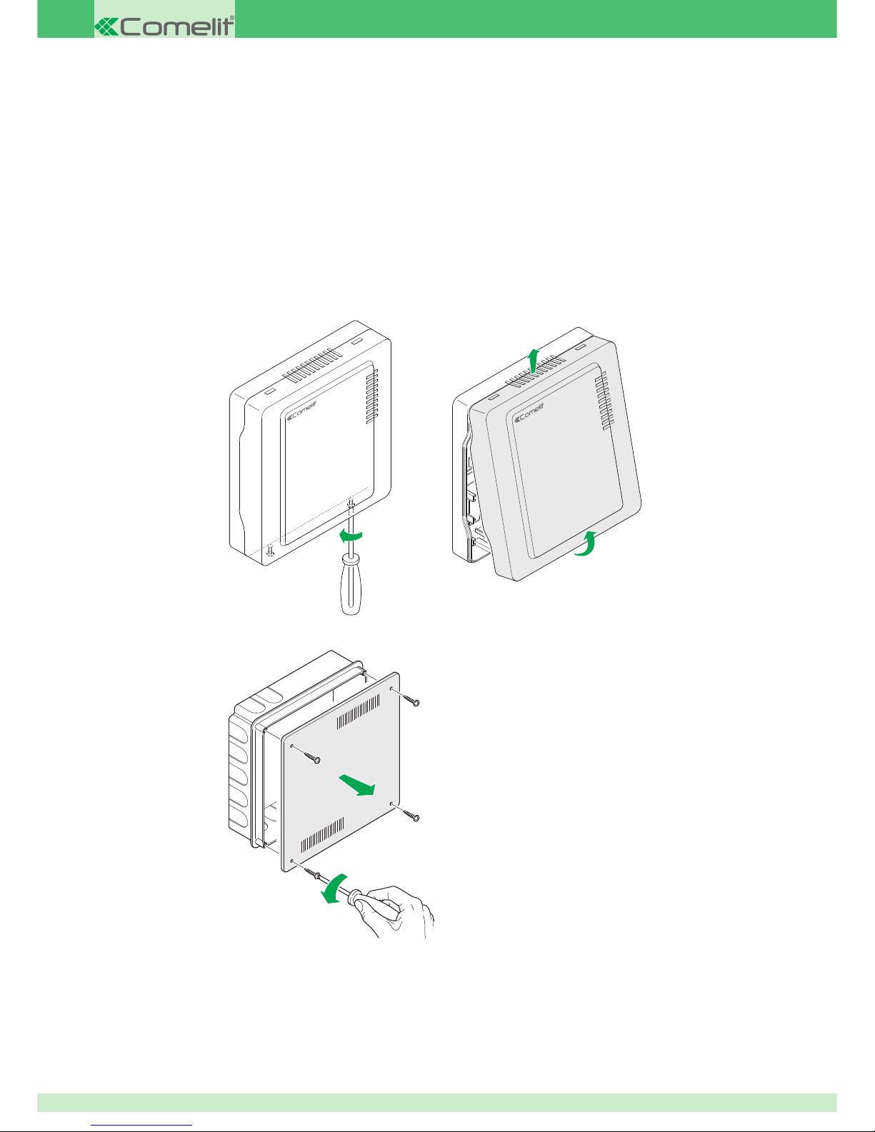
Opening the wall-mounted housing Art. 30002501
1
2
3
1
2
Opening the fl ush-mounted box Art. 30002503
Page 7
7
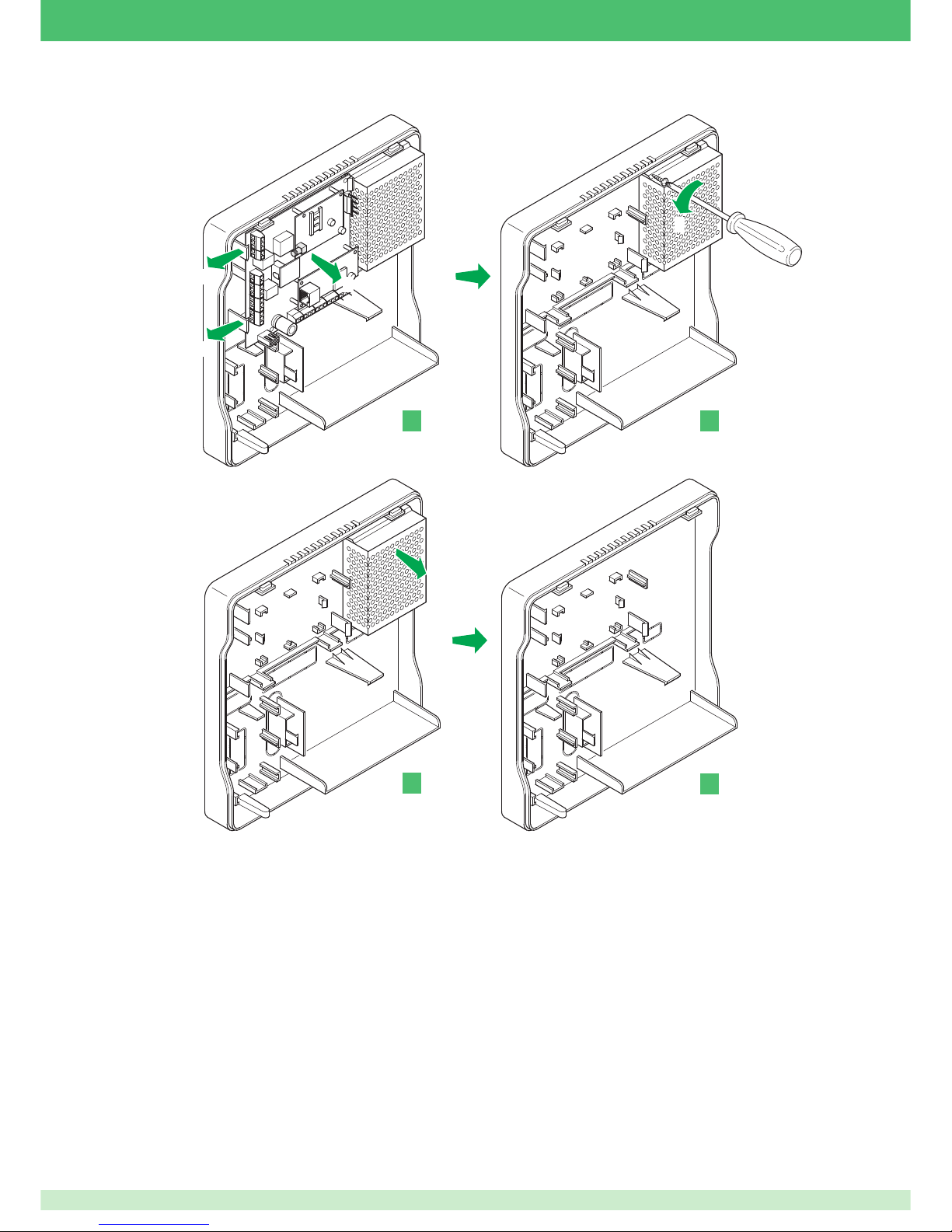
Preparing the housing: once you have opened the housing, before proceeding (if the switchboard is already assembled), remove the electronic
cards and the power supply unit from the bottom of the housing, so as to avoid the risk of damage:
1
1
2
If the input/output expansion module is present, release the retaining clips to remove it. Put it in a clean place.
3
4
1
3
2
4
Page 8
8
Fitting the housing and anti-tear tamper
It is now possible to fi t the housing to the wall:
1. Identify the position in which the switchboard is to be fi tted and make sure that no cable or service ducts (pipes, drain pipes etc.) run through or
close to the fi xing holes. Then, with the help of a pencil or marker pen, carefully mark the position of the 5 fi xing points (4 mobile fi xing points
and one anti-tear bolt anchoring point).
2. Eliminate the pre-marked sections of the cable routing holes that you intend to use.
3. Use 6 mm wall plugs (supplied) to fi x the switchboard to the wall. Drill holes accordingly and insert the wall plugs in the wall.
4. Route the cables through the respective holes.
5. Fix the housing to the wall by tightening the screws fully home into the wall plugs, but without damaging the housing mountings.
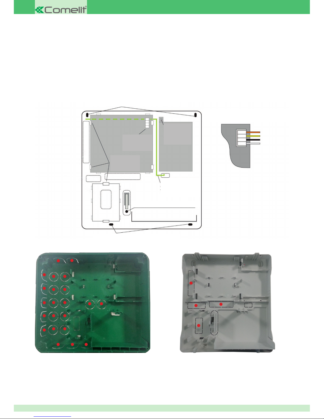
6. You can now refi t the components removed from the housing, starting with the power supply unit for the sake of convenience. To route the
conductors to the switchboard card power connector in an orderly manner, pass them below the power supply unit and then upwards, using
the two recesses in the reinforcing ribs under the PSU for the purpose.
Cable routing for fl ush-mounted box Art. 30002503
Cable routing for wall-mounted box Art. 30002501
DETAIL OF POWER SUPPLY UNIT CONNECTOR:
CORRECT POSITIONING
TELEPHONE
INTERFACE EARTH
CONDUCTOR
POWER SUPPLY
UNIT FIXING
SCREW
PSU
CONNECTOR
RETAINING
CLIPS
HOUSING MOUNTING HOLES
HOUSING MOUNTING HOLES
ANTI-TEAR TAMPER HOLE
Page 9
9
Main features
• 0.75A self-resettable fuse for protecting the power supply to the siren outputs;
• 1.35A self-resettable fuse for protecting the power supply to the RS485 buses;
• 1.35A self-resettable fuse for protecting the power supply to the sensors;
• all the inputs are fi ltered and protected against electrical and electrostatic discharges
• alarm relay with potential-free exchange contact
• 2 programmable logic outputs with confi gurable polarity, limited to 100mA, self- resettable
• built-in digital dialler
• separate power supply unit, switching type direct from mains
• power supply protection against overloads, short-circuits and voltage surges;
• battery connection (up to 7A/h hours –12V) protected against reversed polarity and short-circuits by means of a glass fuse in the power supply
unit
• circuit for dynamic testing of backup battery charge state
• circuit for monitoring the positive siren voltages, 485 bus and sensor auxiliary positive
• on-board 485 bus terminal resistor, which can be activated by means of a jumper
• USB interface for connection to a confi guration system
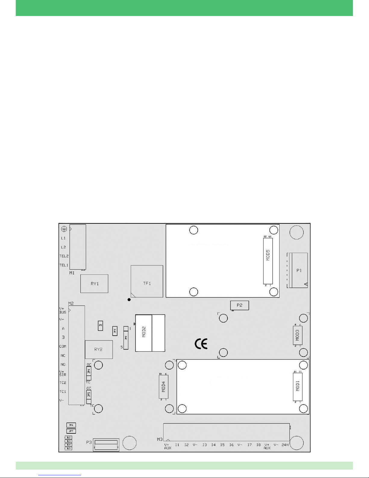
Identifi cation of connections to switchboard terminals
Switchboard card (30001008 - 30001034 - 30001068)
The switchboard card is available in 3 versions with different features; see the table on page 5 for details.
The card has a basic confi guration with 8 freely programmable zones +1 sabotage zone. It has a relay output, which by default, manages the sirens,
and 2 low-consumption programmable outputs. The switchboard card is supplied with a built-in digital dialler, which allows the transmission of voice
messages by means of an additional audio/voice control module.
It is equipped with 8 standard wired zones and one anti-tamper zone. It also has one relay output and 2 confi gurable 100 mA open-collector outputs.
The association of zones to areas and partial subgroups of areas allows total, partial or selective activation of the system,
according to the authorisations assigned at the confi guration stage to the user who performs the operations.
Each input event can be associated with multiple outputs, thus potentially involving all the outputs confi gured at the installation stage. The fl exibility
of this arrangement makes it possible to adapt the switchboard to the most wide-ranging requirements.
GSM COMMUNICATION
MODULE POSITION
IP COMMUNICATION
MODULE POSITION
MESSAGE
EXPANSION PCS
Page 10

10
Module connectors
Name Function
MOD1 IP communication expansion module connection
MOD2 Messages and voice control expansion module connection
MOD3 Reserved
MOD4 Reserved
MOD5 GSM communication expansion module connection
Terminal block M1
Pin Name Function
1 Earth symbol Connection for earthing the telephone line protection devices. Ensures their correct operation.
2 L1 Conductor 1 input from telephone line. Is connected directly to terminal TEL1
3 L2 Conductor 2 input from telephone line
4 TEL2 Conductor 2 output to telephone
5 TEL1 Conductor 1 output to telephone. Is connected directly to terminal L1
Terminal block M2
Pin Name Function
1 V+ BUS Power supply positive for 485 communication bus. Limited to 1.35A
2 V- Power supply negative All terminals marked V- are connected to each other
3 A RS485 data bus - A
4 B RS485 data bus - B
5 COM Connection for alarm relay exchange switchboard pin (RY1)
6 NC Normally closed connection for alarm relay (RY1). In standby the COM and NC terminals are kept closed together.
7 NO Normally open connection for alarm relay (RY1). When the relay is attracted, the COM and NO terminals are kept closed together.
8 V+ SIR Battery charge and power supply positive. Limited to 0.75A
9 TC2
Programmable block logic output. Permitted load 100mA. Polarity is determined by jumper JP5. If JP5 is set to OC, the output acts as an open collector: in
standby, it will not allow the passage of current, and if activated, it will close to earth. If JP5 is set to TC, however, in standby it will not allow the passage of current
and if activated, it will present a positive to the terminal.
10 TC1 As per TC1, but controlled by JP4
11 V- Power supply negative
Terminal block M3
Pin Name Function
1 V+ AUX Power supply positive for system sensors. Limited to 1.35A
2 I1 Programmable input zone 1.
3 I2 Programmable input zone 2.
4 V- Inputs common / Power supply negative
5 I3 Programmable input zone 3.
6 I4 Programmable input zone 4.
7 I5 Programmable input zone 5.
8 I6 Programmable input zone 6.
9 V- Inputs common / Power supply negative
10 I7 Programmable input zone 7.
11 I8 Programmable input zone 8.
12 V+ AUX Power supply positive for system sensors. Electrically connected to terminal 1 of the same terminal block. Shares its limitation.
13 V- Power supply negative
14 24H Programmable anti-tamper input.
Indicator lights
Name Function
DL1 Not present
DL2 Not present
DL3 Switchboard operating
DL4 Not present
DL5 Not present
Confi guration jumpers
Name Function
JP1 If activated, enables 485 bus terminal resistor
JP2 Reserved
JP3 Reset (closing it and then opening it restarts the programme)
JP4 TC2 polarity: Open Collector (OC) or Positive Command on TC (TC)
JP5 TC1 polarity: Open Collector (OC) or Positive Command on TC (TC)
JP6 Restore initial confi guration (see installation paragraph)
JP7 Service input
Power supply connection
Name Function
P1 PSU connector.
Page 11
11
Internal expansions
√ IMPORTANT: any operation involving the assembly or disassembly of expansion modules must be performed with all input power
(from power supply unit or battery) OFF, in order to avoid permanently damaging the expansion module you intend to add or
remove, as well as the switchboard card.
Telephone dialler functions (PSTN as standard)
• telephone line presence check
• number dialling, both pulse and DTMF
• 16 telephone numbers for voice calls and transmission of SMS, email and MMS (the latter three types are available only with the optional
GSM module).
• Contact ID compatible built-in digital dialler
• 4 telephone numbers for Contact ID
• confi gurable test call
• override answering machine option
Messages and Voice Control expansion module (art. 30001303)
Optional, contains the part of the audio messages relating to the digital dialler, i.e. contains the audio messages to be sent on the standard or
GSM telephone line. Equipped with a plug-in connector for simplifi ed fi tting.
The voice control section cannot be customised. It allows an authorised user to perform guided activation, deactivation, modifi cation and status
checking operations on the system from a remote location, using a standard telephone or cellphone.
A second section is provided for the input of custom messages, in other words, all messages intended to provide specifi c information about the
system. This information includes all data relating to alarm signalling (e.g. the data identifying the system address: "Home of Mr John Smith,
Queen Street, London").
The message expansion module does not initially contain any messages and must therefore be confi gured (programmed by means of the
confi guration software) at the time of fi rst installation. The same applies in the event of replacement of or addition to an existing system.
If this module is not fi tted, the only type of audio information that it will be possible to send by telephone is audio tones.
Audio module functions
• Up to 48 standard messages
• 16 freely usable messages (recording and transfer only from PC software)
• 6 service voice messages
• system management by means of interface with voice menu
• facility for activation, deactivation, output status modifi cation and alarm reset from a remote location
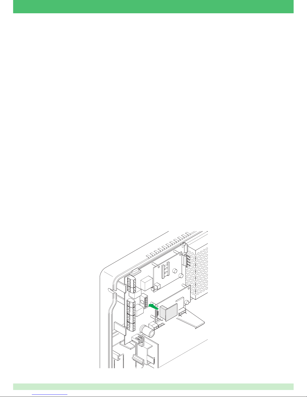
Fitting the messages and voice control expansion module
√ First check that all power is OFF.
To fi t the message and voice control expansion module, simply plug it into connector MOD2. The module connector should plug into its counterpart
without requiring any force.
No auxiliary connection is required.
1
Page 12
12
Fitting the GSM module
√ First check that all power is OFF.
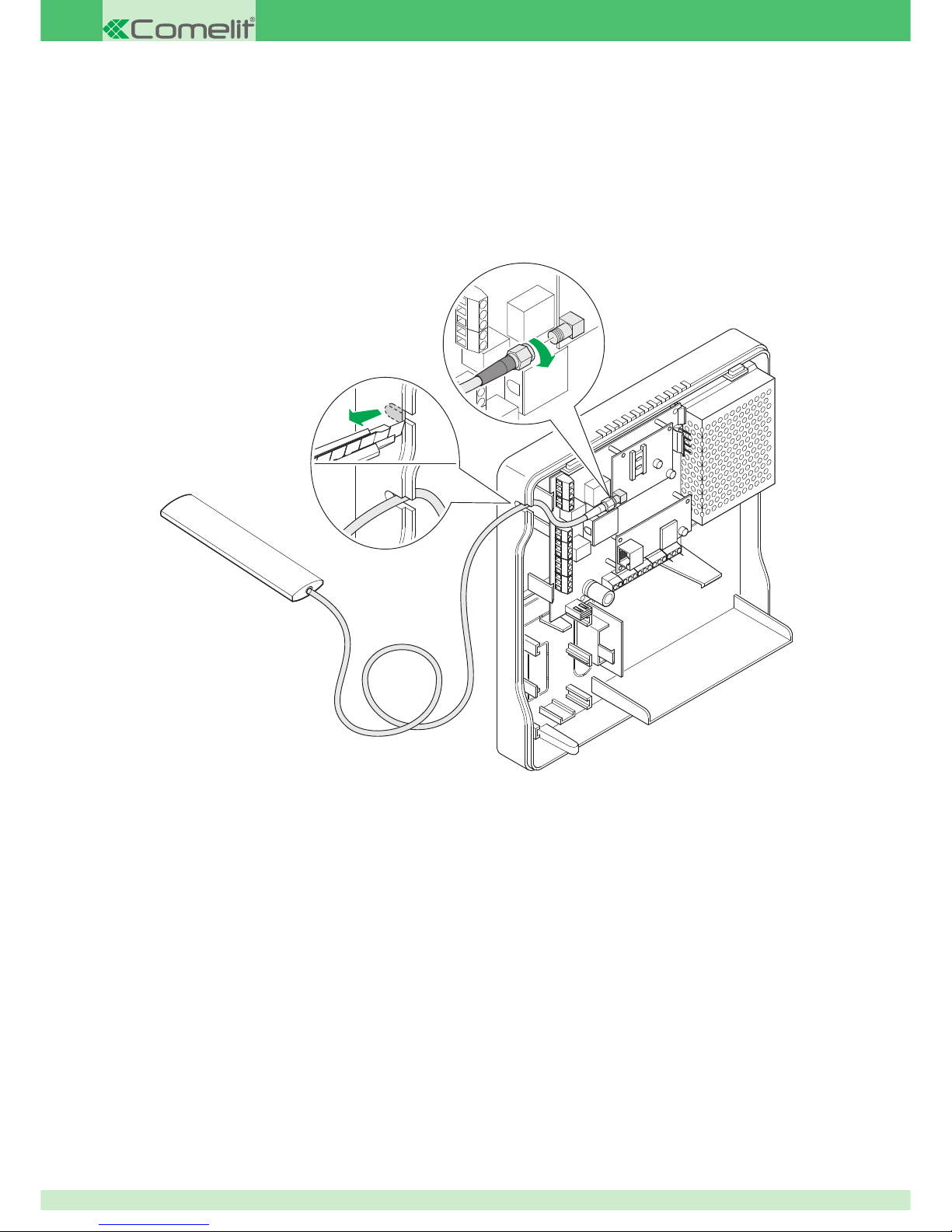
Insert the plastic spacers in the predisposed holes. Then, taking care to plug the module connector into the switchboard connector designated
MOD5 correctly, apply suffi cient pressure to engage the spacers in the GSM expansion card and plug the connector in almost completely.
Once you have fi tted the module correctly, connect the antenna to the respective connector.
IMPORTANT: if the position of the switchboard does not allow the reception of an adequate GSM signal to ensure a good connection, it is
possible, for example, to use an external antenna mounted vertically on the housing. Alternatively, you can move the antenna by using an
extension cable. For this purpose, there is a pre-marked section to allow easy exit of the antenna cable.
1
3
2
GSM communication expansion module (art. 30001301)
Page 13
13
GSM telephone dialler: antenna, SIM card and indicator lights
Once plugged into the switchboard card, the GSM dialler needs only to be connected to the antenna. The antenna must be correctly connected
and its connector must be tightened fully home.
Connecting the antenna
Connect the antenna that you intend to use by tightening the connector on the cable to the gold-coloured connector on the GSM module.
Locating the antenna remotely
If the antenna needs to be located remotely, there is a lightweight section near the top left-hand corner of the housing, which can be easily drilled
so that the shielded cable can be routed out from the switchboard.
Fitting the SIM card
The SIM card must be enabled, and if it is pay-as-you-go type, it must have suffi cient credit on it to be able to make phone calls or send
messages. It is not essential to unlock it, because the switchboard is capable of managing the PIN to unlock the SIM card.
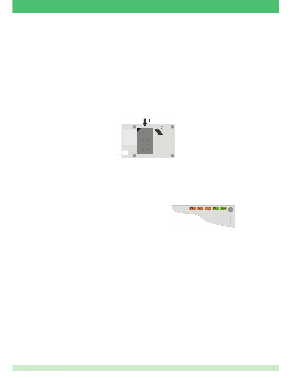
Make sure that the switchboard is not powered up.
1. Gently force the top of the SIM connector towards the centre of the switchboard card (downwards if the switchboard is already mounted on the wall).
2. Once you have overcome the resistance, turn it over on its hinges.
3. Insert the SIM card in the mobile part in such a way that you can see the gold-coloured contacts of the SIM and that the bevelled corner is on the left.
Repeat the sequence in reverse to release the SIM card from its seat.
Meaning of the LEDs on the IP GSM module
The expansion card for GSM network communication is equipped with 5 indicator LEDs for giving information about device status and operation.
The LEDs are designated DL1 to DL5
DL1, red, GSM communication. Flashes when a transfer via the GSM or GPRS network is in progress, e.g. during reception of an SMS or
during registration with the network at the time of initialisation.
DL2, red, module status. Steadily lit upon reset, during initial confi guration of the module and when engaged by the switchboard to communicate
via GSM/GPRS. Flashes in all other conditions.
DL3 and DL4, green, module serial communication. Illuminate briefl y when the module communicates with the switchboard.
DL5, red, radio connection status. Has 5 different states: OFF and
4 different levels of intensity (from control panel Fw version 2.2.1, this
indication is only visible with “service” jumper Jp7 inserted)
OFF: indicates that there is no signal (e.g. antenna or SIM card missing)
ON: four different levels of intensity indicate the level of GSM signal received.
If this indicator is lit, the module is capable of operating.
TCP/IP Ethernet expansion module (art. 30002401)
Provides support for connecting the alarm switchboard to the network. Allows an authorised user to access the switchboard locally or remotely,
using an internet connection. Once connected to the switchboard, users can totally or partially activate and deactivate the areas within their
sphere of competence, and check the status of each input.
Equipped with a plug-in connector for simplifi ed fi tting. Needs to be connected to a LAN with standard 10/100.
SIM
CONNECTOR
Page 14
14
IP network communication module
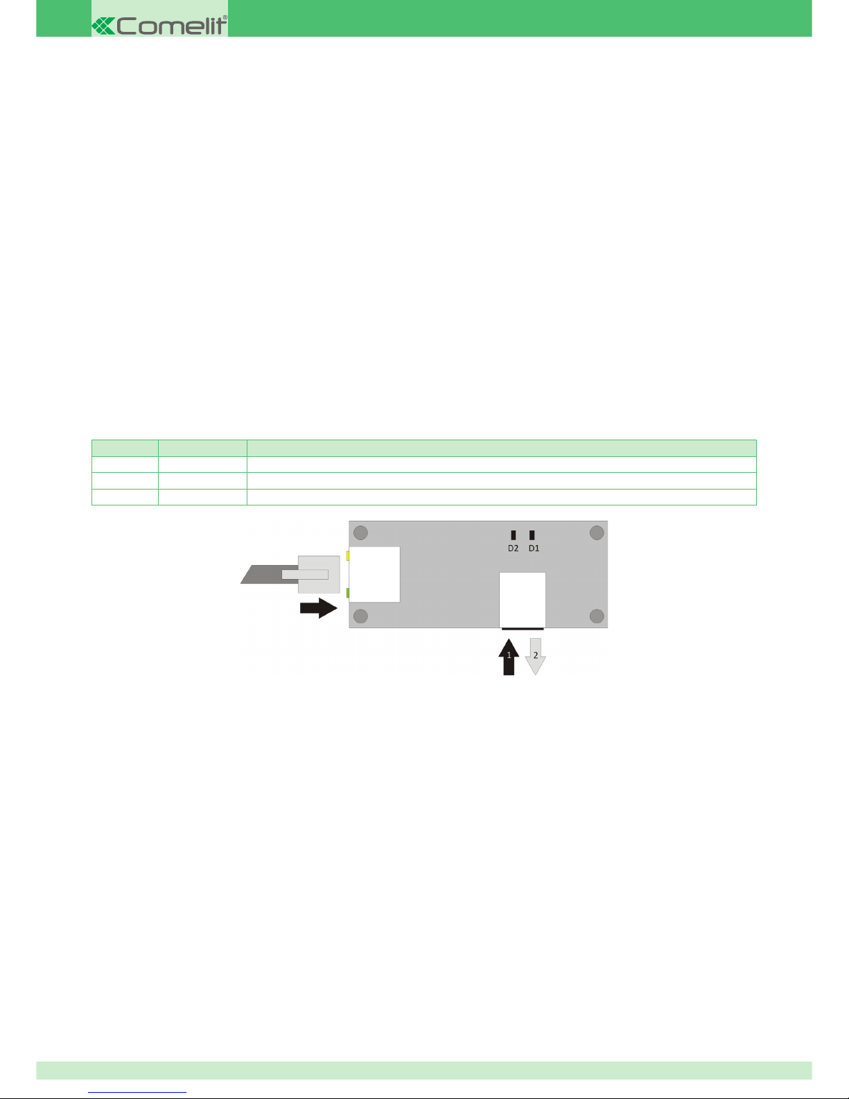
In order to be used, once fi tted on the switchboard card, it must be connected to a 10/100 compatible hub or to a switch of the same specifi cations,
that allows it to be connected to a data network.
For further details see Appendix 3.
Plug the cable in fully, until you feel it engage, in the only accessible connector of the IP communication module, with the tab facing the front
panel of the switchboard housing. To remove the connector from the module, press the same tab down.
Plugging in and unplugging the MicroSD memory card
The IP communication module is equipped with a compartment for a 2GB MicroSD memory card.
To unplug the memory card from its connector:
1. Push the card fully into the connector, then
2. release it: the card will be pushed outwards so that you can grip it more easily.
To plug the memory card back into its connector:
simply insert the card into the connector with the gold-coloured contact not visible, and press it fully home.
Meaning of the LEDs on the IP module
LEDs on the RJ45 network connector:
Yellow LED ON: link OK
Green LED ON: ACT
LEDs on the IP module – Normal operating mode
D1, fl ashing slowly: module operating correctly
D1, fl ashing quickly: module operating but SD memory card missing or defective
D2, fl ashing: confi rms communication with the switchboard
LEDs on the IP module – Programme updating stage
D1 D2 Meaning
Steadily lit: Steadily lit: Updating in progress
Flashing Inverted fl ashing MicroSD card missing
Steadily lit: Flashing MicroSD card missing for a fi le necessary for correct operation
NETWORK CABLE
NETWORK
CONNECTORS
MICRO SD
MEMORY
CONNECTOR
Page 15
15
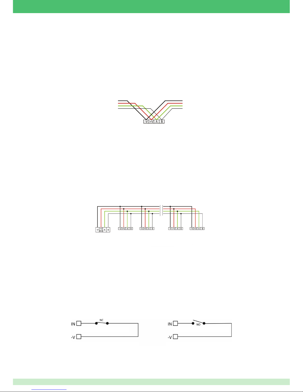
General information about connecting devices to the bus
As a general precaution, note that the 485 bus cable could cause disturbances on cables carrying video or comparable signals, if the two are laid
adjacent to each other. We therefore recommend that you use separate channels for these two types of cable and that you connect the alarm
system bus only with shielded and twisted pair cable with known impedance of 120 Ohm.
Non-compliance with the above may cause communication errors or poor quality communication between modules and switchboard. There is
also a risk that the conductors of the cables themselves might not be shielded correctly.
For correct sizing of cables, refer to the table in Appendix 2.
IMPORTANT: no current must pass through the shields of cables. Shields must not therefore be used as power supply conductors or as return
paths for input circuits. Cable shields must be connected to each other and then connected to the power supply negative at a single point in the
switchboard. This serves the dual purpose of shielding the bus conductors effectively and avoiding ground loops.
IMPORTANT: for correct communication between the devices connected to the bus, it is good practice for the devices themselves to be
interconnected without branches, i.e. avoid star connections as fas as possible. If the use of branches is unavoidable, make sure that they are as
short as possible. Consequently, it is advisable to route the bus cable correctly by adhering to the ideal connection and minimising any deviation
from it. The best way to connect the devices is to use the “in and out” method.
Bus line termination:
The two end devices (the two devices furthest from each other in an ideal layout) balance the line with the appropriate end-of-line resistor (120
ohm). On some devices, this resistor is installed on-board and can be activated by means of a jumper or DIP switch. 2 end-of-line resistors are
supplied with the switchboard, for use when a device without an on-board termination (e.g. RFID key reader) is connected to the end of the line.
IMPORTANT: the switchboard can be positioned at any point along the line, provided that the line is correctly terminated in a 120 Ohm balancing
resistor at both ends, as shown in the guideline diagram.
Wiring the inputs
The inputs routed to the switchboard or to the peripherals on the bus, including bidirectional inputs when used as inputs, are of universal type.
This means that, depending on their physical connection and their parameter settings on the switchboard, they can assume the confi gurations
shown below.
IMPORTANT: balancing resistors, if used, must be installed in the sensor to which they are associated.
NC: detects the opening of a normally closed contact connected between an input terminal and the respective negative (-V). It is not capable of
detecting a line sabotage state: in the event of cutting, it can generate an error or alarm; in the event of a line short-circuit, it does nothing.
NO: detects the closure of a normally open contact connected between an input terminal and the respective negative (-V). It is not capable of
detecting a line sabotage state: in the event of a line short-circuit, it can generate an error or alarm; in the event of cutting, it does nothing.
FROM THE
SWITCHBOARD
SWITCHBOARD:
ENABLE BUS
BALANCING RES.
MODULE N:
ENABLE BUS
BALANCING RES.
MODULE 1
GUIDELINE DIAGRAM
MODULE 2 MODULE N-1
CONNECTION TO THE BUS TERMINALS
CONNECTION TO THE BUS TERMINALS
TO THE NEXT
MODULE
MODULE 1
EXAMPLE OF "IN AND OUT" TYPE CONNECTION
ALARM
A: NORMALLY CLOSED (NC)
ALARM
B: NORMALLY OPEN (NO)
Page 16
16
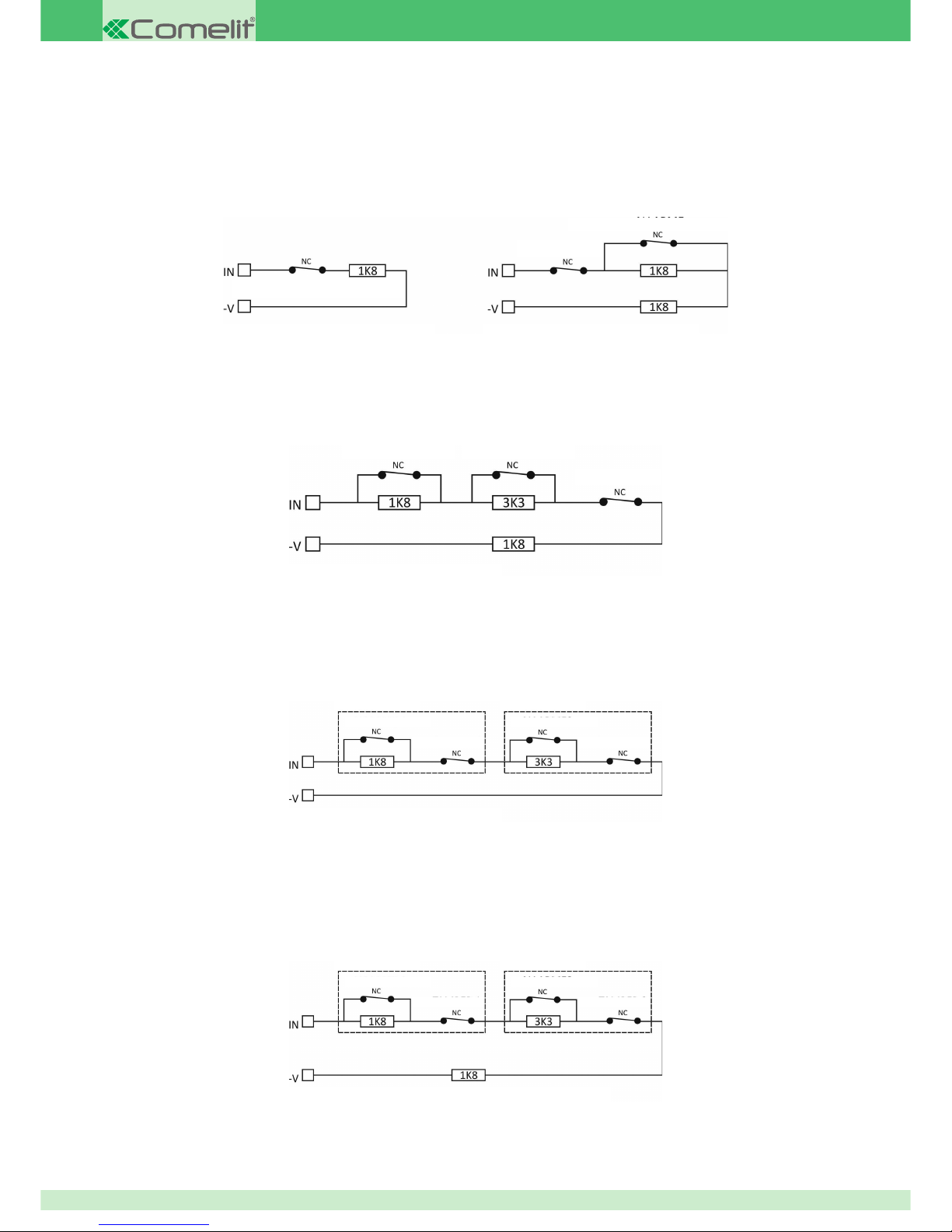
Single balancing
Detects the opening of a normally closed contact disposed in series with a balanced line (on 1.8K) connected between an input terminal and the
respective negative (-V). Detects a sabotage state due to a line short-circuit. In the event of cutting, it can generate an error or alarm.
Double balancing
Detects the opening of a normally closed contact disposed in series with a balanced line (on 1.8K) connected between an input terminal and
the respective negative (-V). Adding a second balancing resistor (also 1.8K) makes it possible to distinguish an alarm state from a line sabotage
state, both in the event of cutting and short-circuit.
Triple balancing
Detects and distinguishes the opening of two normally closed contacts, usually alarm and electrical fault, disposed in series with a balanced line
(on 1.8K) connected between an input terminal and the respective negative (-V). Its ability to distinguish derives from the adoption of a second
balancing resistor (1.8K) disposed in parallel to the fi rst of the contacts to be monitored and a third balancing resistor (3.3K). This confi guration
makes it possible to distinguish between an alarm/electrical fault state and a line sabotage state, both in the event of cutting and short-circuit.
Double zone
Detects and distinguishes the opening of two normally closed contacts, usually relating to two different sensors, disposed in series with a line
with comparable behaviour to that of an NC line, connected between an input terminal and the respective negative (-V). Its ability to distinguish
between the two sensors derives from the adoption of a balancing resistor (1.8K) disposed in parallel to the contact of the fi rst sensor to be
monitored and a second balancing resistor (3.3K) disposed in parallel with the contact of the second sensor to be monitored. It is not capable
of detecting a line sabotage state: in the event of cutting it can generate an error or sabotage; in the event of a line short-circuit it does nothing.
The sabotage can only be generically attributed to the wired line for the input to which it is connected.
Double zone with end of line (EOL double)
Detects and distinguishes the opening of two normally closed contacts, usually relating to two different sensors, disposed in series with a line
with a balanced line (1K8) connected between an input terminal and the respective negative (-V). Its ability to distinguish between the two
sensors derives from the adoption of a balancing resistor (1.8K) disposed in parallel to the contact of the fi rst sensor to be monitored and a
second balancing resistor (3.3K) disposed in parallel to the contact of the second sensor to be monitored. This confi guration makes it possible to
distinguish between an alarm/electrical fault state and a line sabotage state, both in the event of cutting and short-circuit. The alarms are correctly
recognised and assigned to the sensor from which they originate. The sabotage, however, can only be generically attributed to the wired line for
the input to which it is connected.
ALARM
ALARM FAULT
C: SINGLE BALANCED
E: TRIPLE BALANCE
F: DOUBLE ZONE
F: DOUBLE ZONE WITH END OF LINE (EOL DOUBLE)
SENSOR 1
SENSOR 1
ALARM 1
ALARM 1
TAMPER 1
TAMPER 1
SENSOR 2
SENSOR 2
ALARM 2
ALARM 2
TAMPER 2
TAMPER 2
ALARM
TAMPER
TAMPER
D: DOUBLE BALANCED
Page 17
17
Wiring the switchboard's 24-hour input
The 24-hour input must be confi gured as single balance with a resistance of 1,8 KΩ. Refer to the relevant paragraph for information about correct
connection of the tamper lines.
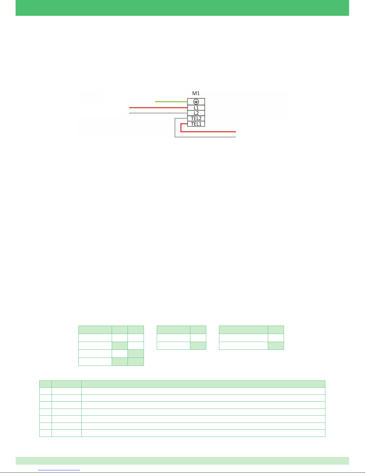
PSTN telephone dialler
To connect the telephone dialler to the telephone network correctly, you must fi rst locate the point at which the line enters the house. The dialler
must be connected as the fi rst device, as viewed from the incoming telephone line.
To ensure that the line protection devices work correctly, it is imperative to earth the corresponding terminal of M1. For this purpose, the housing
is predisposed with a length of insulated copper braid, in yellow/green, to facilitate connection of the earth terminal of switchboard terminal block
M1 to the earth terminal of the power supply unit.
Main control and display components
LCD keypad (art. 30006002)
Using the LCD keypad, authorised users can activate and deactivate the system, check and manage system status as a whole, and check the
events log records.
Using the keypad, it is also possible quickly to modify the system settings and the options of each individual output.
Operations are performed by means of a combination of numerical keys and function keys, whereas feedback is both visual (alphanumeric
display and LEDs) and aural (buzzer.)
The LCD keypad is equipped with 2 freely confi gurable alarm inputs.
Main features:
• Backlit 2 x 16 character LCD display
• initial software addressing, from built-in keypad
• Four LEDs for immediate indication of power ON, battery alarm, generic error and alarm in progress
• Backlit keypad with ten number keys and eleven function keys.
• Two universal inputs, confi gurable as NC, NO, single, double and triple balance, double zone and double zone with termination, with possibility
of direct connection of roller shutter contacts (switch alarm).
• on-board 485 bus end-of-line resistor, which can be activated by DIP switch
• ant-tamper and anti-tear tamper
Meaning of LEDs
The keypad features 4 LEDs; their meaning is as follows, working from top to bottom:
1. Green, Mains Power, steadily lit when the presence of mains power is detected
2. Yellow, Battery, if lit indicates a battery anomaly (disconnected, faulty or with voltage of less than approximately 11.8V)
3. Yellow, Anomaly, if lit indicates that the system is affected by at least one anomaly.
4. Red, Alarm, if fl ashing indicates the presence of an alarm memory state.
DIP switches and bus termination
LCD keypad terminal block description
Pin Name Function
1 I1 Input 1
2 I2 Input 2
3 V- Power supply negative input / Inputs reference
4 B RS485 data bus - B
5 A RS485 data bus - A
6 V- Power supply negative input
7 V+ Power supply positive input
INCOMING TELEPHONE
LINE
TO INTERNAL TELEPHONES
(IF PRESENT)
CONNECT TO EARTH
BUZZER DIP1 DIP2
EXCLUDED OFF OFF
DOWN ON OFF
UP OFF ON
UP ON ON
TAMPER DIP3
ACTIVE OFF
EXCLUDED ON
485 TERMINATION DIP4
EXCLUDED OFF
ENABLE ON
Page 18
18
LCD keypad with RFID key reader (art. 30006003)
The LCD keypad with RFID reader is identical to the standard LCD keypad in every respect, except that it is equipped with an RFID reader
module. This version enables users, according to their authorisations, to activate the system partially or totally or deactivate it, using an RFID
key, without having to enter a code, thereby saving time. It is compatible with Comelit RFID keys.
The RFID reader's antenna is located in the bottom left-hand corner of the housing and is clearly identifi ed by a circular, screen-printed symbol.
The RFID key must be brought close to this area of the housing so that the reader can recognise it correctly.
The connection terminal block is identical to that of the LCD keypad without RFID reader.
Meaning of LEDs
The LEDs have the same meaning as the LEDs on the keypad without RFID reader
Mounting and wiring the keypads
The base of the keypads, both with and without RFID reader, has a series of slots in it to ensure versatility of mounting on a wide range of
supports, starting with the ordinary type 503 box.
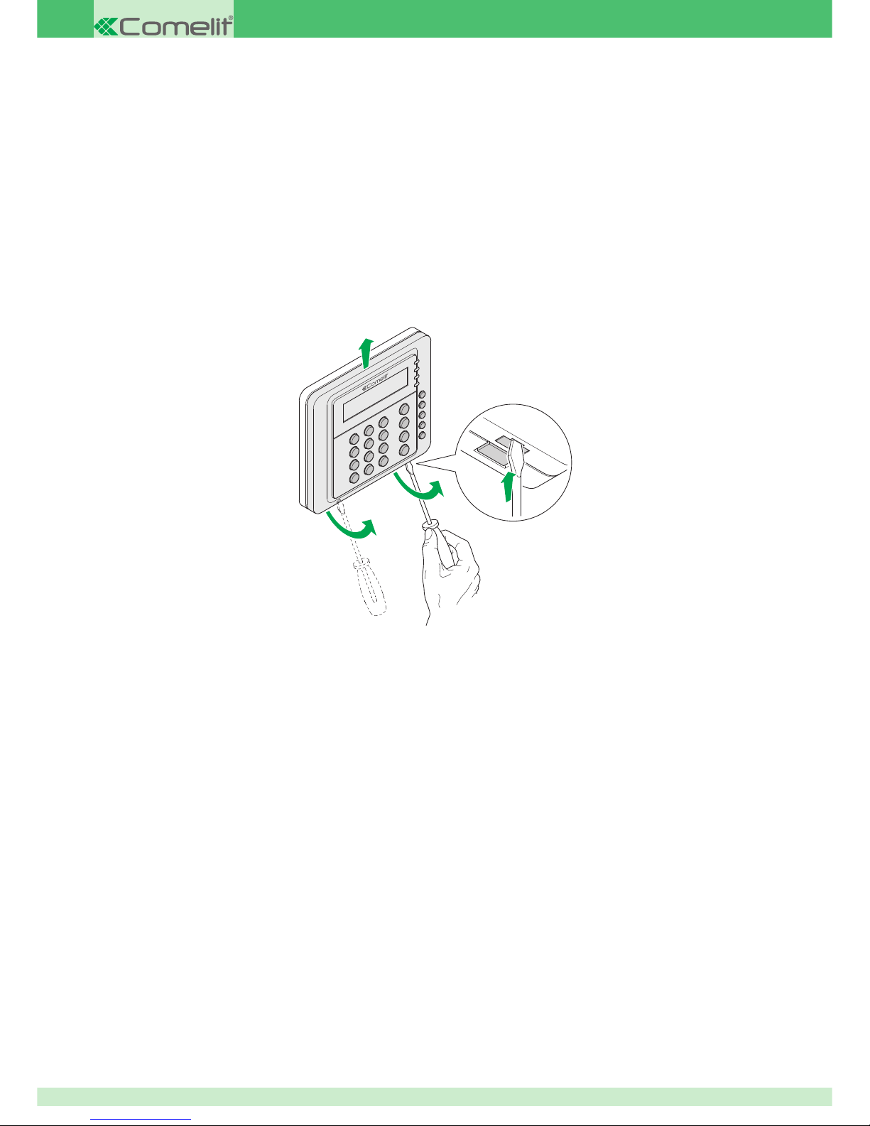
Opening the housing
1
3
2
2
Locate the area with the tamper support, with the pre-marked break-off panel for facilitating detachment of the tamper, and remove the silicon
key acting as a tamper. Put it in a clean place.
Fixing the housing: as there are no other preliminary operations, you can proceed directly with fi xing the keypad.
If the housing is to be fi tted on a type 503 box:
1. Position the base of the keypad with the fi xing holes aligned with the two clips on the 503 box and, using a pencil or marker pen, mark the
position of the hole for the anti-tear bolt (the bolt is on the base, in the bottom right-hand corner), making sure that no electrical or service ducts
(pipes, drainpipes, etc.) are routed through the area.
2. To fasten the pre-set fracture bolt of the tamper, you will be using one of the 5 mm wall plugs supplied, so drill a hole accordingly, with
precision. Insert the bolt in the wall.
3. Insert the connection cable into the main hole in the base and tighten the tamper bolt by a few turns by hand, so as to have a reference point
for correct alignment
4. Fasten the type 503 box using two suitable screws, taking care not to damage the base by overtightening the screws.
If the housing is to be wall-mounted:
1. Locate a suitable position for mounting the housing and make sure that no electrical or service ducts (pipes, drainpipes, etc.) are routed
through or near the holes you intend to use. Then, using a pencil or marker pen, accurately mark the position of the fi xing points, including the
hole for the anti-tear option.
2. To fi x the housing to the wall and anchor the pre-set fracture bolt of the tamper, you will be using 5 mm wall plugs (supplied), so drill
accordingly and insert the wall plugs in the wall.
3. Route the cables through the respective holes.
4. Secure the housing by tightening the screws into the wall plugs until they are fully home, without damaging the mounting points of the housing
IMPORTANT: when closing the housing, remember to refi t the tamper in its place. The black, conductive part must be visible.
Page 19
19
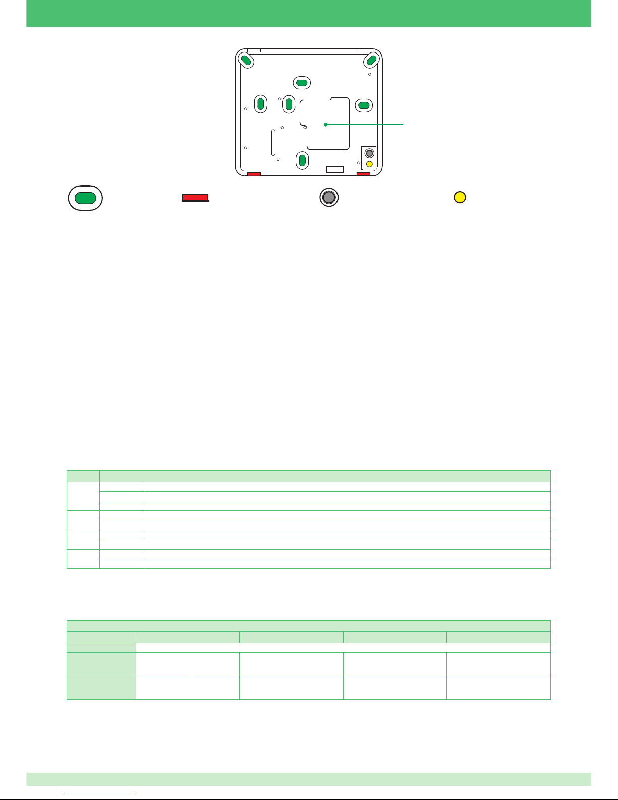
Fixing holes Elastic closure clips
Position of silicone tamper Anti-tear tamper hole
Cable routing
RFID proximity reader on bus (art. 30006104)
The RFID proximity reader on bus allows activation and deactivation with RFID keys without contact. An RFID key can be associated to each
user. Each key can operate on the zones and areas for which the associated user is enabled.
Its mechanical confi guration is such that it can be used directly on all residential series that use an adapter for Keystone standard RJ45 network
connector. It is compatible with Comelit RFID keys.
Main features:
• Simplifi ed mounting with Keystone generic RJ45 adapter on residential series frames
• Four LEDs with partially assignable functions.
• Possibility of quick total activation
• Choice of several activation modes
• Physical addressing of device by means of DIP switches
Meaning of LEDs
The reader has 4 indicator LEDs, the meaning of which varies according to reader status:
t reader in standby (no cycle in progress): LEDs show the operating status of the areas enabled for the reader
t cycle in progress: the LEDs light up in sequence to provide users with an indication of which scenarios are available, allowing them to make
a choice.
The cycle actions associated with the LEDs by default are:
t Red LED: Total activation
t Yellow LED: Scenario P1
t Blue LED: Scenario P2
t Green LED: Scenario P1+P2
IMPORTANT: The actions associated with the LEDs can be changed by the installer during system programming.
The table below lists the meanings of the LEDs while the reader is in standby.
Colour Description
Red
On Scenario associated with the Red LED active
Slow fl ash System not activated and alarm, sabotage or fault event memory present
Fast fl ash System activated and alarm, sabotage or fault event memory present
Blue
On Scenario associated with the Blue LED active
Slow fl ash System activated with unknown scenario (not saved)
Yellow
On Scenario associated with the Yellow LED active
Fast fl ash Fault present
Green
On Scenario associated with the Green LED active
Fast fl ash System not ready for enabling or there are (non-excluded) open zones
The meaning of the LEDs during the selection cycle depends on system confi guration.
As a general rule, consider the following:
• LED steadily lit: the action can be performed without forcing.
• LED fl ashing quickly: the action requires forcing (the system is not ready).
Meaning of activator LEDs during presentation of the key
RED YELLOW BLUE GREEN
OFF Request for deactivation of all areas covered by the reader.
ON
Request for activation of the activation
profi le associated with the RED LED
Request for activation of the activation
profi le associated with the YELLOW
LED
Request for activation of the activation
profi le associated with the BLUE LED
Request for activation of the activation
profi le associated with the GREEN
LED
Flashing quickly:
The reader is forcing the activation
profi le associated with the RED LED
(*)
The reader is forcing the activation
profi le associated with the YELLOW
LED (*)
The reader is forcing the activation
profi le associated with the BLUE LED
(*)
The reader is forcing the activation
profi le associated with the GREEN
LED (*)
(*) The purpose of forcing is to overcome a ‘not ready’ condition in one or more of the zones associated with the areas covered by the reader,
and/or an anomaly which can be overridden due to the choices made at the time of control panel confi guration.
Page 20
20
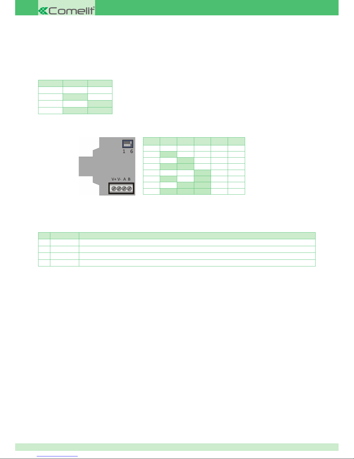
Addressing DIP and bus termination
DIP switches 1 to 5 are for addressing the reader on the bus. On the current version, only addresses 1 to 8 are used, so DIP switches 4 and 5
must be left on OFF.
485 line termination
If the RFID reader is connected as the fi nal point of the bus line, you need to connect a 120 ohm 1/4W 5% resistor in parallel to the 485 bus line,
i.e. between terminals A and B.
RFID key reader on bus terminal block description
Pin Name Function
1 V+ Power supply positive input
2 V- Power supply negative input
3 A RS485 data bus - A
4 B RS485 data bus - B
Mounting the RFID key reader on bus
To mount the RFID key reader, you need to use an interface plate for standard Keystone RJ45 sockets that is compatible with the residential
series you intend to use.
Simply connect the adapter to the plate and then plug the reader into the adapter, pressing it fully home until you hear the two parts engage.
RFID keys (art. SK9050x/A)
The keys are made using high-security, bidirectional RFID transponders.
The technology used is such that the keys can communicate with the reader without any need for electrical contacts and hence with problems
of contact wear. This ensures that performance remains high over time.
Used in conjunction with the RFID readers (on bus, on keypad, on Safetouch, on Minitouch or on Planux Manager), they make it possible to
activate and deactivate the system without any need for electrical contact. An RFID key can be associated to each user. Each key can operate
on the zones and areas for which the associated user is enabled.
They are available in various colours and their housing is shaped in such a way that they can easily be added to a bunch of keys on a keyring,
so that they are always to hand.
Setting RFID reader speed
IMPORTANT: when fi rst powered up, the RFID readers on bus automatically set themselves to a speed of 38400 baud. To change the speed
proceed as follows:
• With the device powered up, set DIP switch n°6 to ON. The LEDs on the RFID will light up until they are all lit, and will then all go off and start
lighting up again (learning mode)
• In this state, set DIP switch n°1 and n°2 as shown in the table below to set the desired speed
• Once you have set the speed, return DIP switch n°6 to OFF. The speed is now set
• Set DIP switches 1 to 5 according to the address to be set, as per the paragraph below
Note that the standard speed of the VEDO switchboards bus is 38400 baud.
Baud DIP 1 DIP 2
9600 OFF OFF
38400 ON OFF
57600 OFF ON
115200 ON ON
N° DIP1 DIP2 DIP3 DIP4 DIP5
1 OFF OFF OFF OFF OFF
2 ON OFF OFF OFF OFF
3 OFF ON OFF OFF OFF
4 ON ON OFF OFF OFF
5 OFF OFF ON OFF OFF
6 ON OFF ON OFF OFF
7 OFF ON ON OFF OFF
8 ON ON ON OFF OFF
Page 21
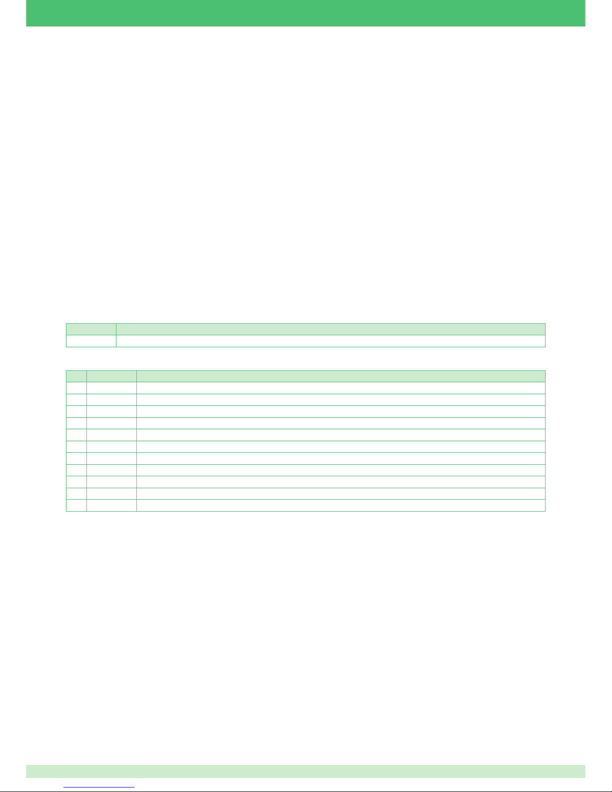
21
Other devices that can be connected to the 485 bus
Safetouch (art. 30006001) / Minitouch (art. 20034607) with RFID key reader
Safetouch/Minitouch is an innovative interface equipped with a touch screen, via which authorised users can interact with the alarm system.
The level of interaction makes it possible to perform all operations than can be done from the keyboard, whether relating to use, confi guration or
control by the user. The combined use of text, symbols and colours makes the available functions immediately comprehensible.
As well as offering alarm system management features, Minitouch is capable of interacting with the Simplebus home automation system, thereby
ensuring integration between the two systems.
Minitouch is equipped with three bidirectional lines as standard, which are identical to those of the input and output expansion module and are
hence fully programmable and can be used both as I/O lines connected to the security system, or assigned to home automation use.
The RFID reader provided as standard enables users, according to their authorisations, to activate the system partially or totally or deactivate it,
using an RFID key, without having to enter a code, thereby saving time. It is compatible with Comelit RFID keys.
The position of the RFID reader's antenna is on the right-hand side of the Safetouch/Minitouch, and is clearly identifi ed by a symbol screen-
printed on the surface of the frame. The RFID key must be brought close to this area of the housing so that the reader can recognise it correctly.
The predisposed mountings are designed for fi tting Safetouch/Minitouch on a standard type 503 box.
Main features:
• 3.5” resistive touch panel
• Optical tamper
• 485 bus interface for direct alarm interfacing
• Simplebus interface for home automation interfacing (only with Minitouch)
• Basic bridging from alarm to home automation (facility for data exchange between alarm and home automation) (only with Minitouch)
• Alarm keypad simulation for confi guration purposes
• Built-in RFID reader as standard
485 line termination
Name Function
JP8 If activated, connects the line termination to the 485 bus line
Safetouch/Minitouch terminal block description
Pin Name Function
1 V+ Power supply positive input
2 V- Power supply negative input, common to home automation bus
3 D Data Signal for home automation Simplebus
4 A RS485 data bus - A
5 B RS485 data bus - B
6 NC1 Output 1 relay normally closed contact
7 COM1 Output 1 relay common
8 NO1 Output 1 relay normally open contact
9 I1 Programmable input/output connection
10 I2 Programmable input/output connection
11 I3 Programmable input/output connection
Addressing and speed confi guration of Safetouch/Minitouch bus
Like any other device connected to the 485 bus, the Safetouch/Minitouch must also respond to a single address. This can be confi gured by
programming the Safetouch/Minitouch from its display.
If there is no bus signal (e.g. if the power is ON but the 485 bus is not connected):
• A pop-up appears on the display prompting you to confi gure the device address and bus speed. If the device has already been confi gured,
you do not need to do anything
• If the device still needs to be confi gured, or if the existing confi guration needs to be changed, select Device Address
• Enter the desired address number and confi rm, then
• Select Bus Speed: the possible options will appear, one of which will be active
• Select the desired speed, then select Exit.
For more detailed information about confi guring Safetouch/Minitouch, refer to the specifi c Safetouch/Minitouch instructions.
Page 22
22
Addressing and speed confi guration of Planux Manager bus
Like any other device connected to the 485 bus, the Minitouch must also respond to a single address. This can be confi gured by programming
the Planux Manager from its display.
If there is no bus signal (e.g. if the power is ON but the 485 bus is not connected):
• A pop-up appears on the display prompting you to confi gure the device address and bus speed. If the device has already been confi gured,
you do not need to do anything
• If the device still needs to be confi gured, or if the existing confi guration needs to be changed, select Device Address
• Enter the desired address number and confi rm, then
• Select Bus Speed: the possible options will appear, one of which will be active
• Select the desired speed, then select Exit.
For more detailed information about confi guring Planux Manager, refer to the specifi c Planux Manager instructions.
Guidance on the installation of Safetouch, Minitouch and Planux Manager
Safetouch/Minitouch
Safetouch/Minitouch is intended for installation using the mountings of a standard, pre-installed type 503 box.
Preparation: insert the tip of a slim screwdriver between the two slots on the right-hand side of the bezel to separate the mounting frame from
the electronics and display part.
Fixing:
1. Using suitable fasteners for securing the frame to the mounting points of the 503 box on the wall, fi x the Safetouch/Minitouch frame to the type
503 box with screws, taking care not to damage the frame by overtightening the screws.
2. Once you have made the necessary connections, refi t the display part to the frame, fi rst using the clips on the left-hand side and then exerting
slight pressure on the right-hand edge, to help join the remaining clips.
Planux Manager
For instructions on how to mount Planux Manager, see the specifi c sheet supplied with the Planux Manager bracket.
Expansions on 485 bus
Expansion on bus with 8 balanceable inputs and 8 logic outputs on bus (art. 30003101)
Each input can be confi gured as NC, NO, single, double and triple balance, double zone and double zone with termination.
Set to detect tampering if the housing is opened or the unit is removed from the wall.
Tampers can be disabled.
Planux Manager with RFID key reader (art. 20034801)
Planux Manager is the built-in supervisor for the range: as well as incorporating all the control features available on Minitouch, it performs
advanced, full-duplex video entry functions, with dedicated, programmable function keys. It does not have any alarm inputs or outputs.
Planux Manager terminal block description
Pin Name Function
1 +VS Not used
2 D Data Signal for home automation Simplebus
3 B RS485 data bus - B
4 A RS485 data bus - A
5 S- Call repeater device connection
6 S+ Call repeater device connection
7 CFP Floor door call input
8 CFP Floor door call input
9 L Video door entry bus line connection terminal
10 L Video door entry bus line connection terminal
11 - Power supply negative input, common to home automation bus and alarm bus
12 + Power supply positive input
485 line termination
Planux Manager also offers the possibility of inserting an end-of-line resistor for the 485 communication part.
Name Function
CV8 If activated, connects the line termination to the 485 bus line
Page 23
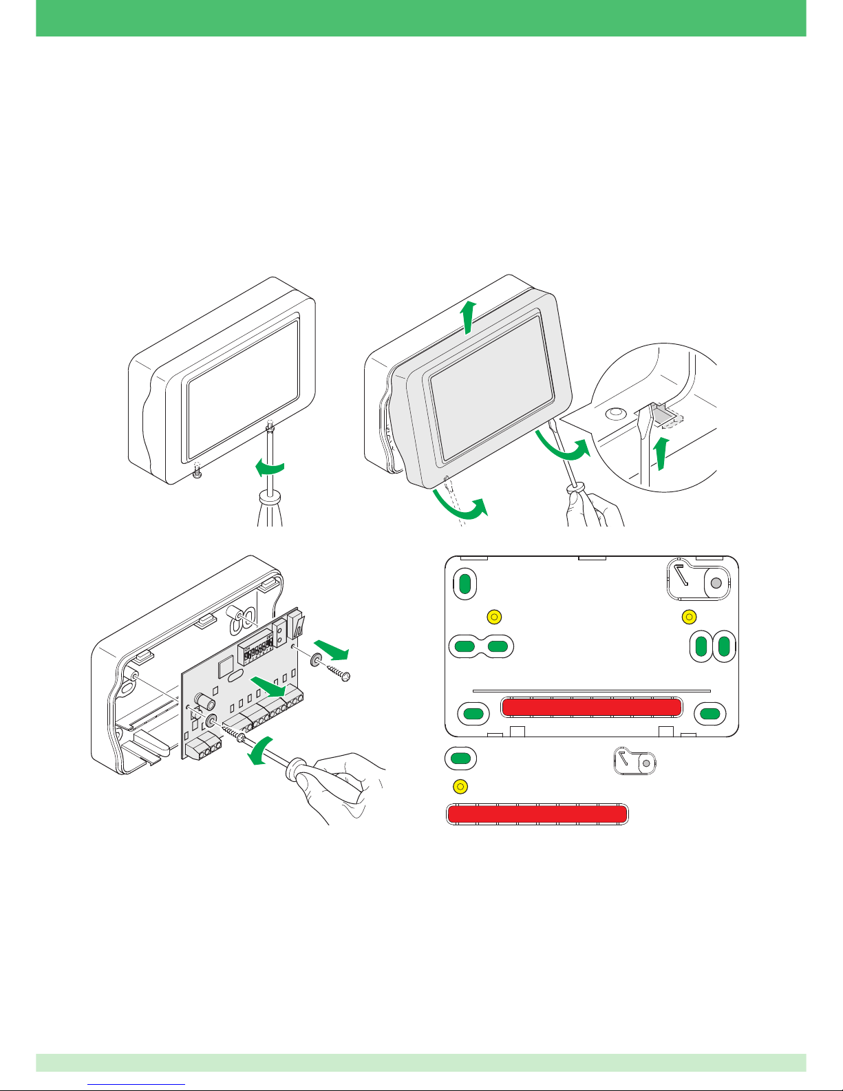
23
Fitting the expansions in a small external housing
A maximum of two input/output expansions can be fi tted inside the switchboard, but others can be distributed in the fi eld. The advantage of a
decentralised solution is that it requires fewer cables inside the switchboard enclosure. For this purpose, a housing has been produced which
has all the necessary predispositions for taking full advantage of the features of the expansions module.
Their housing is pre-drilled in such a way as to make them suitable for fi tting in fl ush-mounted wall boxes and for more generic wall-mounting. A
pre-marked section on the bottom is for routing the cables through, and another pre-marked section in the top right-hand corner, coinciding with
a fi xing hole, provides anti-tear protection.
IMPORTANT: to ensure anti-tear protection, the hole associated with the pre-marked area with anti-tear function must always be anchored to
the wall. Failure to anchor this section will make the anti-tear protection useless.
The expansion module is fi xed to the base of the housing with 2 self-tapping screws.
Opening the housing: the cover is secured to the base by means of three fasteners on the top and two spring clips at the bottom. There are
also two safety screws to prevent accidental opening.
1
4
1
3
3
2
Preparing the housing: once you have opened the housing, remove the electronic card and predispose the cable inlet.
1
3
2
Wall mounting holes
Card fi xing holes
Cable inlet hole
Anti-tear hole
Fixing the housing: as there are no other preliminary operations, you can proceed directly with fi xing the housing.
1. If you are fi tting the housing in a predisposed box, locate a suitable position for mounting the housing and make sure that no electrical or
service ducts (pipes, drainpipes, etc.) are routed through or near the holes you intend to use. Then, using a pencil or marker pen, accurately
mark the position of the fi xing points, including the hole for the anti-tear option.
2. Use 5 mm wall plugs (supplied) to fi x the housing to the wall. Drill holes accordingly and insert the wall plugs in the wall.
3. Route the cables through the respective holes.
4. Secure the housing by tightening the screws into the wall plugs until they are fully home, without damaging the mounting points of the housing
IMPORTANT: when refi tting the expansion card in its housing, make sure that the anti-tear tamper (the one furthest to the left as viewed in the
illustrations) is held properly closed by the tab originating from the pre-marked anti-tear area of the housing.
Page 24
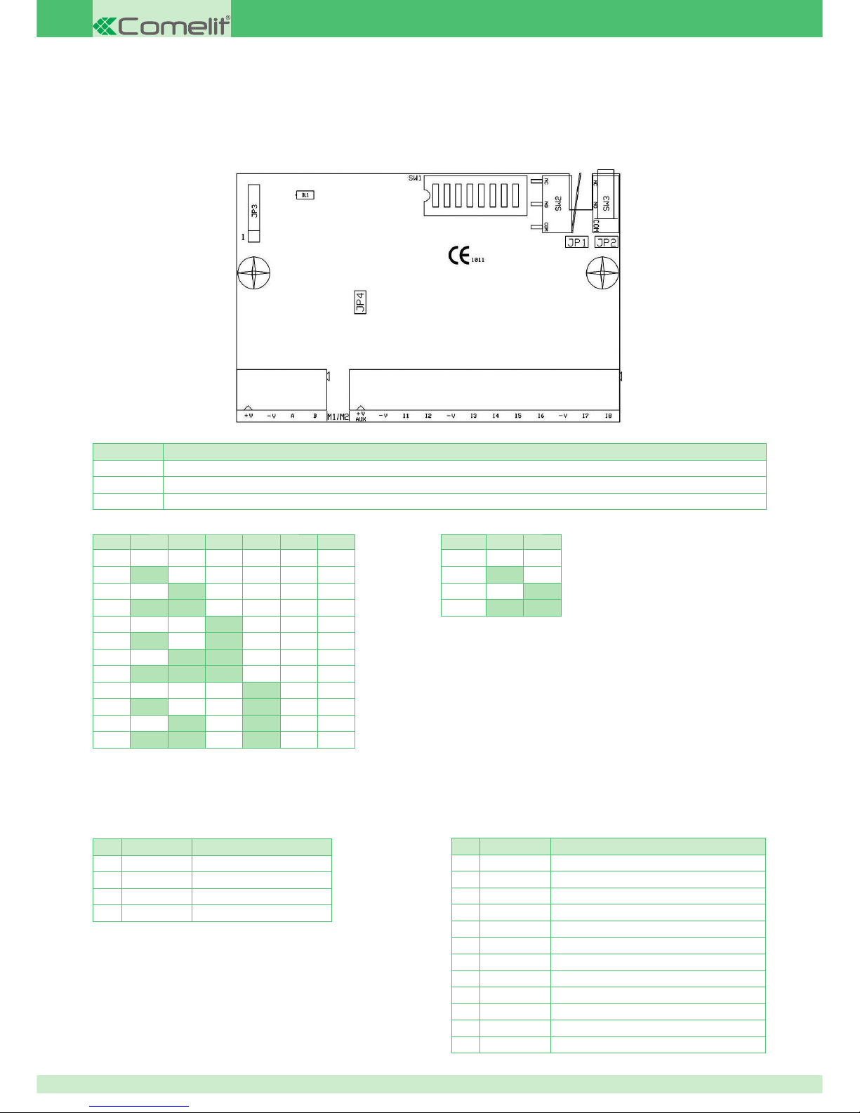
24
Correlation table: position of DIP switches SW1, device n° and bus speed
DIP switches 1 to 6 are for addressing the reader on the bus. On the current version, only addresses 1 to 12 are used, so DIP switches 5 and 6
must be left on OFF.
Note that the standard speed of the VEDO switchboards bus is 38400 baud.
Input/output expansion module terminal block description
M1
Pin Name Function
1 V+ Power supply positive input
2 V- Power supply negative input
3 A RS485 data bus - A
4 B RS485 data bus - B
M2
Pin Name Function
1 V+ AUX Power supply positive output.
2 V- Power supply negative - output reference
3 I1 Input 1 / Output 1
4 I2 Input 2 / Output 2
5 V- Power supply negative input / Inputs reference
6 I3 Input 3 / Output 3
7 I4 Input 4 / Output 4
8 I5 Input 5 / Output 5
9 I6 Input 6 / Output 6
10 V- Power supply negative input / Inputs reference
11 I7 Input 7 / Output 7
12 I8 Input 8 / Output 8
BAUD DIP7 DIP8
9600 OFF OFF
38400 ON OFF
57600 OFF ON
115200 ON ON
N° DIP1 DIP2 DIP3 DIP4 DIP5 DIP6
1 OFF OFF OFF OFF OFF OFF
2 ON OFF OFF OFF OFF OFF
3 OFF ON OFF OFF OFF OFF
4 ON ON OFF OFF OFF OFF
5 OFF OFF ON OFF OFF OFF
6 ON OFF ON OFF OFF OFF
7 OFF ON ON OFF OFF OFF
8 ON ON ON OFF OFF OFF
9 OFF OFF OFF ON OFF OFF
10 ON OFF OFF ON OFF OFF
11 OFF ON OFF ON OFF OFF
12 ON ON OFF ON OFF OFF
Main features
• 8 alternatively confi gurable inputs/outputs
• Inputs can be confi gured as NC, NO, single, double and triple balance, double zone and double zone with termination.
• Possibility of direct connection with roller shutter contacts (switch alarm)
• Outputs can be confi gured as monostable, monostable with confi gurable pattern, bistable or bistable with confi gurable pattern
• Anti-tamper and anti-tear tamper
• On-board 485 bus end-of-line resistor, which can be activated by means of a jumper
• Addressing by means of DIP switch
Confi guration jumpers description
Name Function
JP1 If activated, disables anti-removal (anti-tear) tamper
JP2 If activated, disables anti-opening tamper
JP4 If activated, enables 485 bus terminal resistor
Page 25
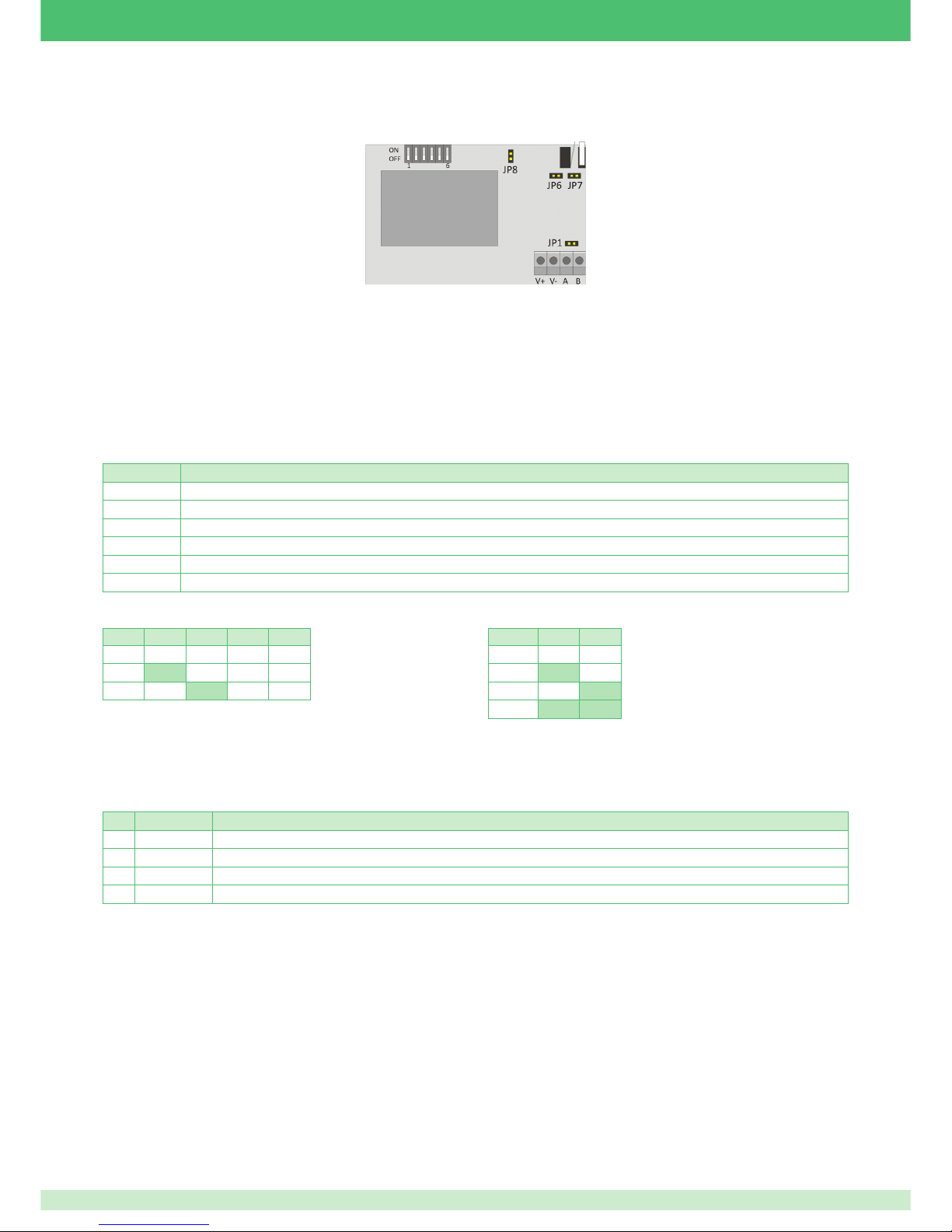
25
Confi guration jumpers description
Name Function
JP1 If activated, enables 485 bus terminal resistor
JP3 Reserved
JP4 Reserved
JP6 If activated, disables anti-removal (anti-tear) tamper
JP7 If activated, disables anti-opening tamper
JP8 TBD
Correlation table: position of DIP switches SW1, device n° and bus speed
DIP switches 1 to 4 are for addressing the reader on the bus. On the current version, only addresses 1 to 3 are used, so DIP switches 3 and 4
must be left on OFF.
Note that the standard speed of the VEDO switchboards bus is 38400 baud.
Radio expansion module terminal block description
Pin Name Function
1 V+ Power supply positive input
2 V- Power supply negative input
3 A RS485 data bus - A
4 B RS485 data bus - B
Bidirectional radio expansion on bus (art. 30003201)
The modules operate in bidirectional mode (reception and transmission). This makes it possible to associate radio controls, radio alarm sensors
(contacts and/or volumetric detectors) and supervised wireless sirens to the switchboard.
Main features
• Up to 32 radio zones per module
• Up to 16 radio outputs (including max 8 sirens)
• Up to 8 radio sirens
• Possibility of bidirectional communication
• Operating frequency in 868 MHz band, FSK mode
• Sensor and siren status monitoring
• Separate management of intruder and sabotage alarms
• Radio device power supply monitoring, including sirens
• Supervision
Wireless sensors and accessories
Wireless connectable devices
Bidirectional Pet Immunity infrared sensor, via radio
Bidirectional magnetic contact via radio
Bidirectional 4-key radio control
Self-powered indoor siren
Self-powered outdoor siren
For the above devices, refer to the specifi c product instructions.
Guidance on the installation of wireless sensors and sirens
For the correct positioning and mounting of wireless sensors and sirens, refer to the specifi c instruction sheets enclosed with the devices in
question.
N° DIP1 DIP2 DIP3 DIP4
1 OFF OFF OFF OFF
2 ON OFF OFF OFF
3 OFF ON OFF OFF
BAUD DIP5 DIP6
9600 OFF OFF
38400 ON OFF
57600 OFF ON
115200 ON ON
Page 26
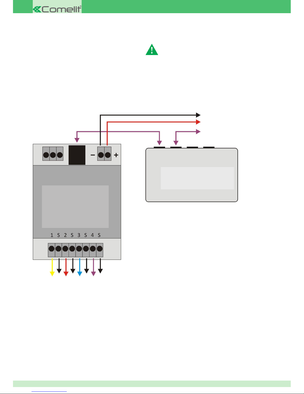
26
PAL/IP video module art. 30001445
The PAL/IP video module allows interaction between the video surveillance apparatus and the switchboard for MMS communication
MMS – system description and minimum requirements
IMPORTANT: To be able to use the MMS function, the system has to include the GSM and IP modules.
After confi guring the system correctly, the MMS function will:
• inform the recipient, by MMS, of an alarm event relating to a zone covered by a specifi c camera (only one camera can be associated to a
given zone).
• include in the same message up to 4 different frames captured at different times by the camera associated to the zone in alarm.
Network parameters of PAL/IP module
The PAL/IP module must be correctly recognised by the switchboard by means of a known network address. In default confi guration, the PAL/
IP module has the following parameters:
IP Address: 192.168.1.233
Submask: 255.255.255.0
Port: 9069
These parameters can be modifi ed when you confi gure the system.
LOCAL NETWORK
HUB OR SWITCH
SIGNAL CONNECTION TERMINALS
FOR 4 CAMERAS
TO SWITCHBOARD 12V
POWER SUPPLY
NETWORK CABLE TO
SWITCHBOARD IP MODULE
NETWORK CABLE
PAL/IP
CONVERTER
IMPORTANT:
Use module 30001445 with revision index (RI) greater than or equal to 005
ONLY with VEDO switchboards updated with SW 2.1 or higher.
Page 27
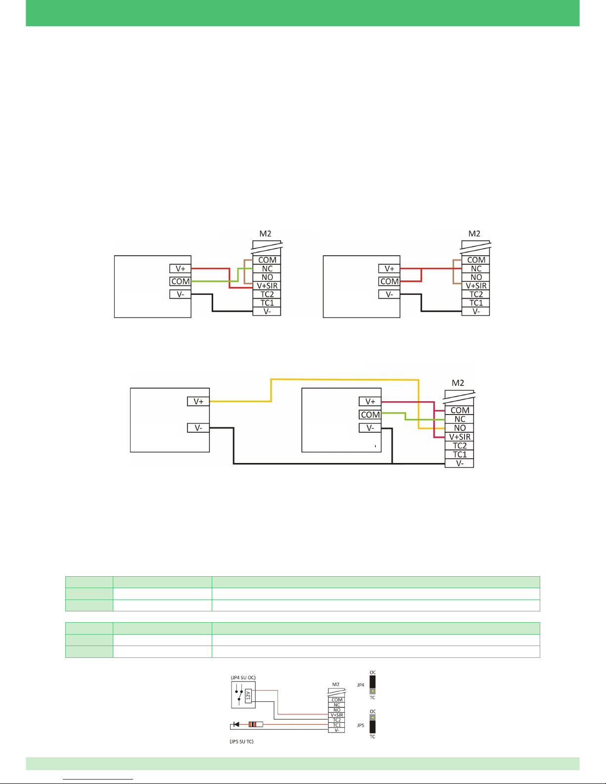
27
Outputs
Siren connection examples
The switchboard is equipped with a relay capable of supporting 3A at 24VDC, with potential-free exchange, which is assigned by default to the
control of an alarm sounder. This relay can be used to control a self-powered siren and a standard siren. The exchange is accessible via the
terminals COM (common), NC (exchange closed to common in standby) and NO (exchange open in standby) of terminal block M2.
A positive dedicated to charging the battery of a self-powered unit is available on terminal V+SIR of terminal block M2. This positive is limited by
a 2A resettable fuse.
Connecting a self-powered siren with 3 or 2 wires
With 3-wire connection, the switchboard passes only one block positive through the relay associated to the alarm; the siren power supply is
connected separately to two terminals on the switchboard (V+SIR and V-). In an alarm state, the block positive is removed and the siren sounds,
being able to use its backup battery and the system battery.
With 2-wire connection, the switchboard passes a block positive and recharges through the relay associated to the alarm. The siren negative is
connected to the switchboard V-. In an alarm state, this positive is removed and the siren sounds under its own power.
Compared with 3-wire connection, since the siren and system batteries are separate when the siren sounds, if the residual capacity of the siren
battery is low (partially discharged, defective or old), this does not compromise the switchboard functions: the siren might sound only briefl y, but
none of the switchboard functions (logic operation, GSM communication or communication to PSTN line) will be infl uenced by the siren battery.
Connecting a non-self-powered indoor siren
It is sometimes necessary to connect an additional, non-self-powered, indoor siren as backup for the outdoor siren. Using two-wire connection
for the outdoor self-powered siren simplifi es the wiring, as shown in the circuit diagram below.
Example of connection to outputs TC1 and TC2
Terminal block M2 has two generic outputs, TC1 and TC2. These outputs can be confi gured as open collectors for earth or for positive.
Output confi gured as OC. If the output is confi gured as an open collector (OC), in standby the output will be fl uctuating (=no voltage) but in active
status it will close terminal TC to V-.
Output confi gured as TC. If the output is confi gured as a camera (TC), in standby the output will be fl uctuating (=no voltage) but in active status
it will close terminal TC to positive.
This type of response is decided by the confi guration of the two jumpers.
For the connection of LEDs or small relays, refer to the diagram below.
OUTPUT TC1 JP5 ON OC JP5 ON TC
ON Output connects terminal to earth. Output assumes value of approximately 13V.
OFF Output remains fl uctuating. Output remains fl uctuating.
OUTPUT TC2 JP4 ON OC JP4 ON TC
ON Output connects terminal to earth. Output assumes value of approximately 13V.
OFF Output remains fl uctuating. Output remains fl uctuating.
3-WIRE CONNECTION
SELF-POWERED CONNECTION AND INDOOR SIREN
2-WIRE CONNECTION
SELF-
POWERED SIREN
SELF-
POWERED SIREN
SELF-
POWERED SIREN
INDOOR
SIREN
EXTERNAL RELAY ON TC2 OC MODE
EXTERNAL LED ON TC1 TC MODE
Page 28
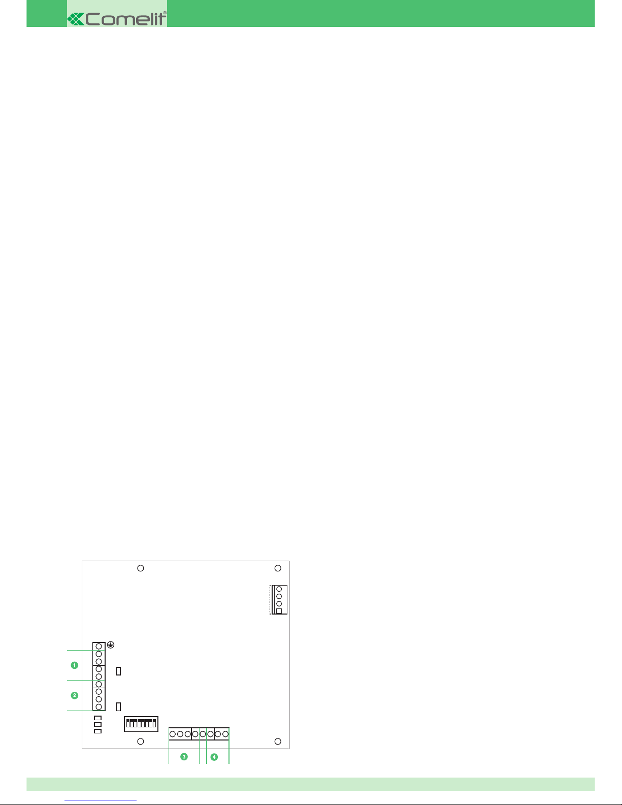
28
Power supply units with dynamic battery testing
1.5A – (art. 30076101)
This is a switching power supply unit limited in current and protected against short-circuiting on the output and against battery inversion. If the
polarity of the battery is inverted, a 6.3A fuse in the metal housing blows.
Rated output voltage is 13.85V and maximum rated current is 1.5A. It informs the switchboard when the battery is charging. Connection to the
switchboard is by means of a multiple-pole connector, whereas connection to the battery is with fast-on connectors.
A distinguishing feature of the unit is its dynamic battery testing function, which enables you to assess the real effi ciency of the battery when it
has to deliver current.
3A – (art. 30076102)
This is a switching power supply unit limited in current and protected against short-circuiting on the output and against battery inversion. If the
polarity of the battery is inverted, a 6.3A fuse in the metal housing blows. Connection to the switchboard is by means of a multiple-pole connector,
whereas connection to the battery is with fast-on connectors. A two-pole terminal block is also available, which provides an independent pick-up
point for the 13.8V.
Rated output voltage is 13.85V and maximum rated current is 3A. It informs the switchboard when the battery is charging.
A distinguishing feature of the unit is its dynamic battery testing function, which enables you to assess the real effi ciency of the battery when it
has to deliver current.
5A – (art. 30076103)
This is a switching power supply unit limited in current and protected against short-circuiting on the output and against battery inversion. If the
polarity of the battery is inverted, a 10A fuse in the metal housing blows. Connection to the switchboard is by means of a multiple-pole connector,
whereas connection to the battery is with fast-on connectors. A two-pole terminal block is also available, which provides an independent uptake
point for the 13.8V.
Rated output voltage is 13.85V and maximum rated current is 5A. It informs the switchboard when the battery is charging.
A distinguishing feature of the unit is its dynamic battery testing function, which enables you to assess the real effi ciency of the battery when it
has to deliver current.
Power supply unit management card for VEDO series control panels
Art. 30003106
This device can be used to expand VEDO series systems by providing:
• A new branch to the RS485 data BUS, electrically isolated, with corresponding power supply output.
• 2 auxiliary power supply outputs.
• 3 Open Collector indication outputs.
• One terminal for tamper contact.
The auxiliary power supplies provided by the card are acquired by the mains power supply units connected to connector J1.
The Open Collector outputs are confi gured to provide fault and anomaly indications.
• If the power supply unit is not connected to a control panel, the indication delay times are as follows:
• Power supply network alarm delay: 1 minute.
• Battery alarm delay: 5 minutes.
• When the device is connected to a VEDO series control panel, it is possible to monitor the status of the auxiliary power supplies and the
power supply unit itself. In this case the fault indication times can be confi gured (using the Safekey keypad or the Safe Manager software).
JP2
J1
JP1
V+
VA
B
V+
VA
B
DL1
DL2
DL3
V+ AUX1V-V+ AUX2V-24H0102
03
12345678
Description of Art. 30003106
1. Data BUS in
2. Data BUS out
3. Outputs Power Supply
4. Outputs
Page 29
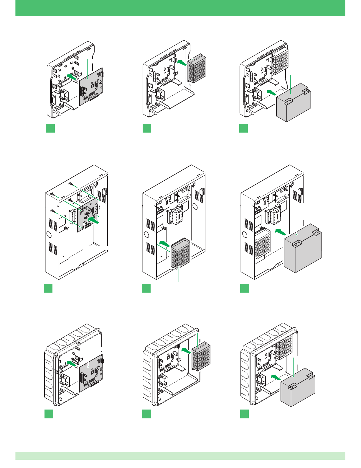
29
Art. 30003106
Art. 30076101
(13,8V/1,5A)
2
Art. 30076003
(12V/7Ah)
31
immagine 3
Art. 30076101 (13,8V/1,5A)
Art. 30076102 (13,8V/3A)
Art. 30076103 (13,8V/5A)
2
Art. 30076003
(12V/7Ah)
Art. 30076004
(12V/15Ah)
31
Art. 30003106
Art. 30076101
(13,8V/1,5A)
2
Art. 30076003
(12V/7Ah)
31
Art. 30003106
Art. 30002501 Plastic wall-mounted housing for VEDO control panels
Art. 30002502 Metal wall-mounted housing for VEDO control panels
Art. 30002503 Plastic fl ush-mounted housing for VEDO control panels
For details relating to card, power supply unit and battery installation, please refer to the manuals for the housings used. Housings,
power supply units and batteries are sold separately.
Page 30
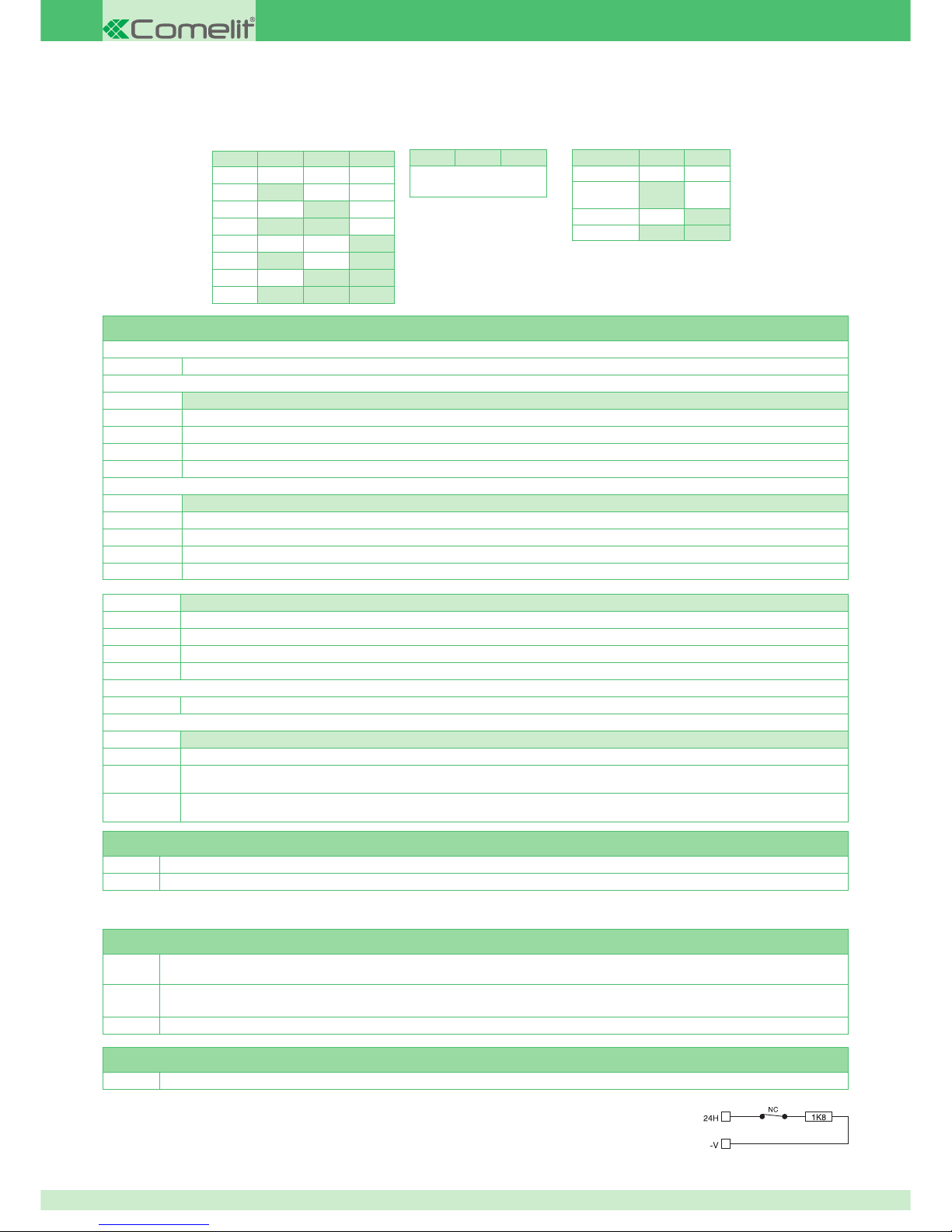
30
Addressing the BUS and setting its speed via dip switch
Note that the standard speed of the bus for VEDO control panels is 38400 baud.
The device address must be unique and can only be programmed using dip switches.
DIP4 DIP5 DIP6
not
used
No.
DIP1 DIP2 DIP3
1 OFF OFF OFF
2 ON OFF OFF
3 OFF ON OFF
4 ON ON OFF
5 OFF OFF ON
6 ON OFF ON
7 OFF ON ON
8 ON ON ON
BAUD DIP7 DIP8
9600 OFF OFF
38400
(default)
ON OFF
57600 OFF ON
115200 ON ON
Terminal block description
Earth
Earth connection terminal
BUS IN
V+
485 communication BUS power supply input positive
V-
485 communication BUS power supply input negative
A
RS485 data BUS for connection to the control panel (IN) - A
B
RS485 data BUS for connection to the control panel (IN) - B
BUS OUT
V+
Power supply positive output. 485 communication bus. Limited to 1.5A
V-
Power supply negative - output reference. 485 communication BUS power supply
A
RS485 data BUS for connection to other devices (OUT) - A
B
RS485 data BUS for connection to other devices (OUT) - B
OUTPUTS POWER SUPPLY
V+AUX1
Auxiliary 1 power supply output positive. Limited to 1.5A
V-
Auxiliary 1 power supply output negative
V+AUX2
Auxiliary 2 power supply output positive. Limited to 1.5A
V-
Auxiliary 2 power supply output negative
24H
Tamper contact input
OUTPUTS
O1
Open collector output 1. Programmed as module Anti-Sabotage by default. The output is active when module sabotage occurs.
O2
Open collector output 2. Programmed as module Low Battery Anomaly by default. The output is active when the programmed time has elapsed since
the moment at which the battery was no longer detected or the voltage at its terminals is 10.7 Vdc or 15 Vdc.
O3
Open collector output O3. Programmed as module No 230V Mains Anomaly by default. The output is active when the programmed time has
elapsed since the moment at which the network was no longer detected.
Confi guration jumpers
JP1
RS485 output termination*
JP2
RS485 input termination*.
* Always remember to insert an end-of-line resistor between A and B of the 485 connection (using the relevant jumpers) to the two ends of the
main BUS line.
LED signals
DL1
Flashing slowly: no data transfer over BUS at the speed set using the dip switch.
Flashing quickly: data transfer over BUS in progress.
DL2
Off:
the peripheral is communicating correctly.
Very slow fl ashing:
(approx. 3 seconds) no data package on the BUS.
DL3
On: indicates that one of the Open Collector outputs is under protection due to a short circuit.
PSU connector
J1
External 230 V - 50 Hz power supply unit connector
The 24H terminal needs the Tamper contact to be connected in single balanced confi guration.
A resistance of 1.8KΩ, in series with the contact, is required.
Tamper contact connection
ALARM
SINGLE BALANCED
Page 31
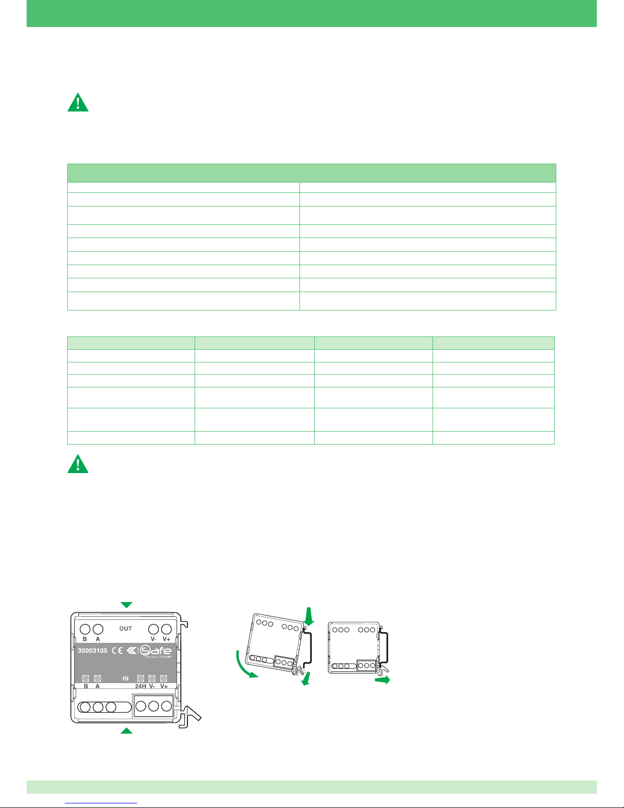
31
The incoming RS485 BUS (BUS IN) is electrically isolated from the rest of the card. As a result, the V- input terminal must only be connected to
the BUS running towards the control panel.
For standard-compliant installation, connect the earth terminal to the system earth, passing through the power supply earth connection using the
yellow/green cable supplied with the device housings.
Connecting V- reference terminal
Earth connection
Do not connect the V- terminal for the incoming BUS to other V- terminals present, and do not use it as a reference for
outgoing power supply voltage values.
This could damage the devices used, or cause them to malfunction.
Art. 30003106 technical specifi cations
Output voltage operating range (VBUS, VAUX1, VAUX2) 10.3 - 14.5 Vdc
V+BUS IN input voltage operating range 10 - 15 Vdc
Maximum Open collector output current: O1-O2-O3 100 mA
Maximum current for Outputs V+AUX1, V+AUX2, V+ BUS OUT 1.5 A
Operating temperature +5°C to +40°C, Relative Humidity 90%
Dimensions - card only (W x H x D) 140 x 127 x 23 mm
Weight - card only 90 g
Consumption in standby 25 mA
Batteries supported
Art. 30076003 - 12V and 7Ah
Art. 30076004 - 12V and 15Ah
Features linked to the type of power supply unit connected to terminal J1:
Power supply unit 30076101 30076102 30076103
Power supply unit type (EN50131-6) TYPE A TYPE A TYPE A
Input voltage 100 - 240V ± 10% 100 - 240V ± 10% 100 - 240V ± 10%
AC input frequency 50 ~ 60 Hz 50 ~ 60 Hz 50 ~ 60 Hz
Output voltage
13.8 Vdc ± 2%
(1.5A Max)
13.8 Vdc ± 2%
(3A Max)
13.8 Vdc ± 2%
(5A Max)
Batteries that can be connected
Art. 30076003 12V/7Ah
Art. 30076004 12V and 15Ah
Art. 30076003 12V/7Ah
Art. 30076004 12V and 15Ah
Art. 30076003 12V/7Ah
Art. 30076004 12V and 15Ah
Output voltage ripple 150mV 150mV 300mV
To guarantee system certifi cation, the power supply unit must be positioned in boxes protected by an anti-opening switch, or in the control
panel housing. The 24h input must be connected to a balanced line, and connected to a VEDO system input line.
BUS Isolator Art. 30003105
This device can be used to isolate the system so that any faults or sabotage events which occur downline do not affect the entire system.
The device is equipped with a dual connection to the VEDO system 485 BUS:
The section of the system that you want to isolate from the rest must be connected to the OUT port.
The plastic container allows fl ush mounting in residential series boxes or on DIN rails (see fi g. 2).
• the IN port (input);
• the OUT port (output).
1
23
4
DL2JP2
DL1JP1
Page 32
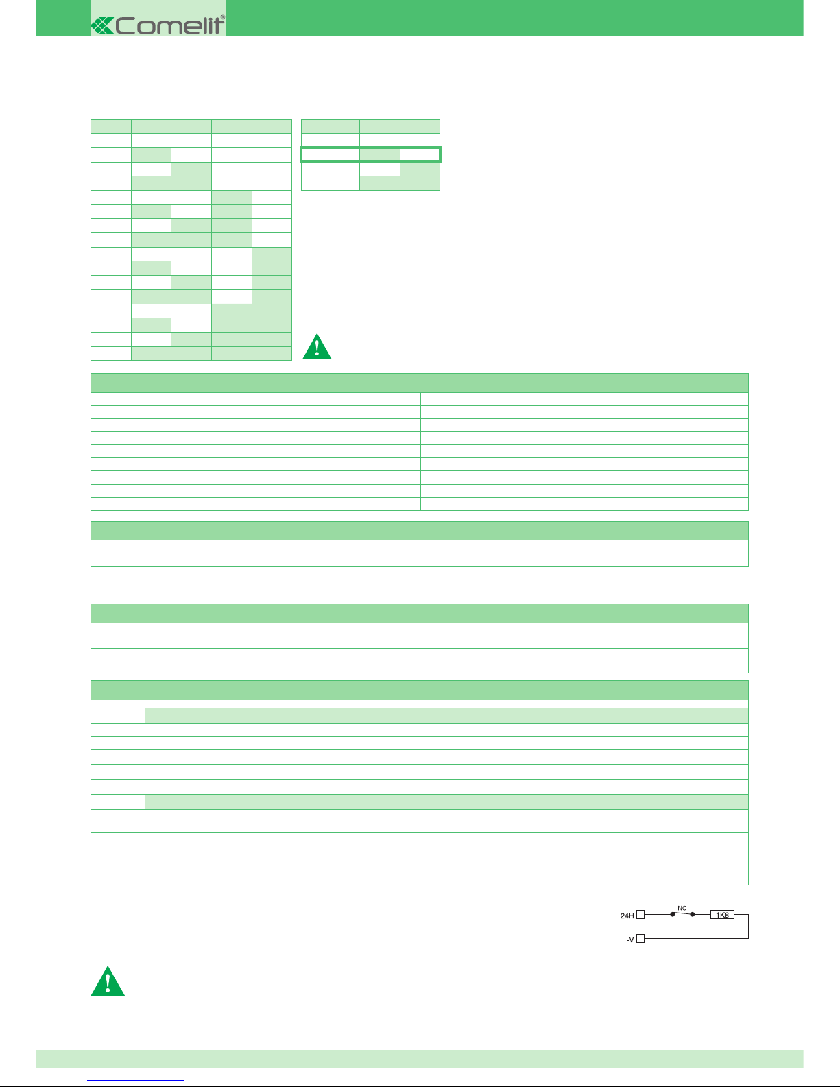
32
Note that the standard speed of the VEDO control unit BUS is 38400 baud (see table 4).
The device address must be unique and can only be programmed using dip switches (see table 3).
Addressing the BUS and setting its speed via dip switch
N°
DIP1 DIP2 DIP3 DIP4
1 OFF OFF OFF OFF
2 ON OFF OFF OFF
3 OFF ON OFF OFF
4 ON ON OFF OFF
5 OFF OFF ON OFF
6 ON OFF ON OFF
7 OFF ON ON OFF
8 ON ON ON OFF
9 OFF OFF OFF ON
10 ON OFF OFF ON
11 OFF ON OFF ON
12 ON ON OFF ON
13 OFF OFF ON ON
14 ON OFF ON ON
15 OFF ON ON ON
16 ON ON ON ON
BAUD DIP5 DIP6
9600 OFF OFF
38400 ON OFF
57600 OFF ON
115200 ON ON
default
To access dip switch S1 and jumpers JP1 and JP2, you must remove the plastic
casing at the top.
Technical characteristics
Rated voltage 13.8 Vdc
Minimum input voltage 10.3 Vdc
Maximum input voltage 14.5 Vdc
Output voltage interval 10.3 - 14.5 Vdc
Consumption 40 mA (max)
Maximum output current 500mA
Operating temperature -10°C/+40°C R.H. 75%
Dimensions [mm] 44x44x19 mm
Weight 50 g
Confi guration jumpers
JP1 If activated, enables 485 BUS input terminal resistor*
JP2 If activated, enables 485 BUS output terminal resistor*
* Always remember to insert an end-of-line resistor between A and B of the 485 connection (using the relevant jumpers) to the two ends of the
main BUS line.
LED signals
DL1
Slow fl ashing: no data transfer over BUS at the speed set using the dip switch.
Flashing quickly: data transfer over BUS in progress.
DL2
Off: the peripheral is communicating correctly;
Very slow fl ashing: (approx. 3 seconds) no data package on the BUS.
BUS isolator terminal block
IN
B RS485 data BUS for connection to Input B of the control panel serial line
A RS485 data BUS for connection to Input A of the control panel serial line
24H Tamper contact input
V- Power supply negative input
V+ Power supply positive input
OUT
B
RS485 data BUS, detects operating anomalies around the output branch and intervenes by isolating the faulty or sabotaged branch.
Terminal B for peripheral input connection via BUS
A
RS485 data BUS, detects operating anomalies around the output branch and intervenes by isolating the faulty or sabotaged branch.
Terminal A for peripheral input connection via BUS
V- Power supply negative output
V+ Power supply positive output
Tamper contact connection
The 24H terminal needs the Tamper contact to be connected in single balanced confi guration. A resistance
of 1.8KΩ, in series with the contact, is required.
In the event of V+ V- power supply shortage, the auto-reset fuse intervenes. For the reset to take place correctly, the power supply must be
cut off for one minute.
ALARM
SINGLE BALANCED
To guarantee system certifi cation, the isolator must be positioned in boxes protected by an anti-opening switch, or in the control panel
housing. The 24h input must be connected to a balanced line.
Page 33
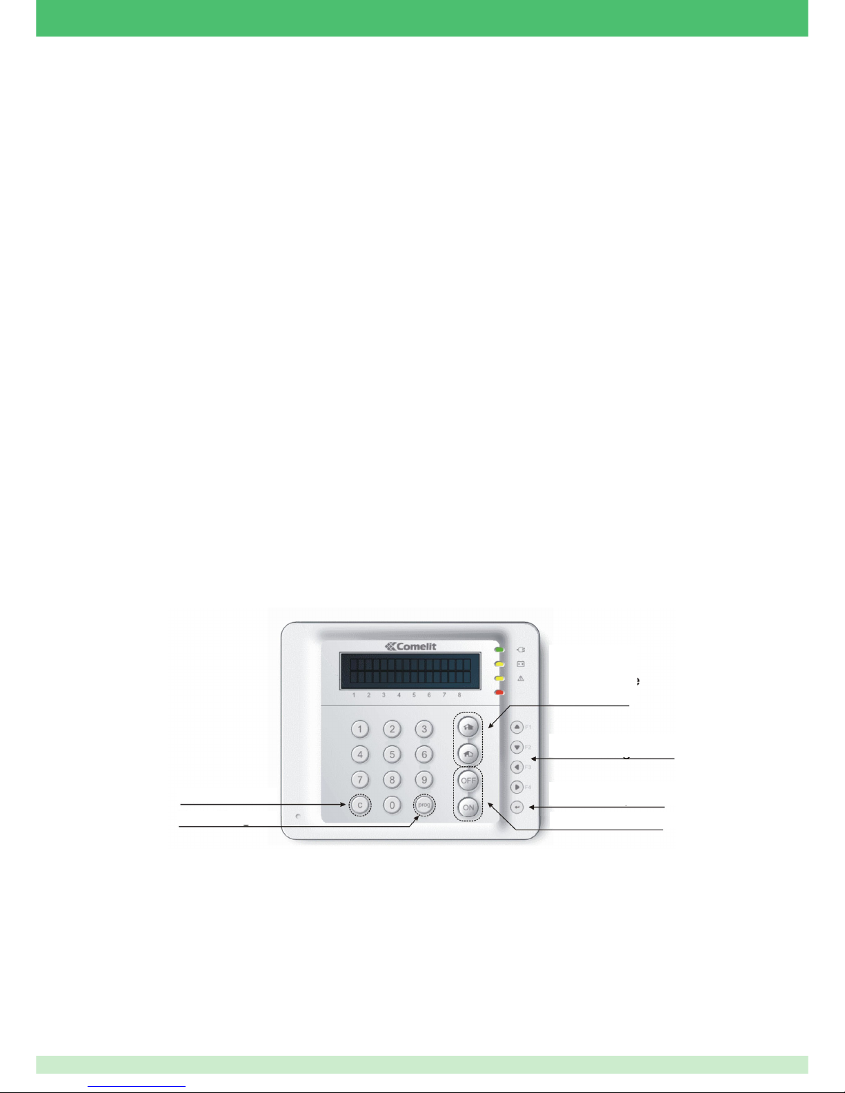
33
What to do before powering up the system
Connect the zone inputs correctly
Make sure that all the inputs are connected correctly (closed to negative directly or via suitably sized resistors, according to the confi guration of
the individual inputs).
Connect the bus modules
Make sure that all the modules are connected to each other correctly and to the alarm switchboard.
Remember to make as straight a connection as possible (in and out type), and that any branches must be as short as possible.
Always remember to insert an end-of-line resistor between A and B of the 485 connection to the two ends of the main bus line.
Set the addresses of the bus devices
Make sure that the addresses of the bus devices have been set correctly, either by means of DIP switches or by confi guration (e.g. keypad)
Close all the anti-tamper inputs
Close all the enclosures of the bus modules and of the switchboard or, alternatively, bypass the anti-tamper microswitches.
Remember that the anti-tamper inputs can be confi gured only in double balance mode.
IMPORTANT: upon fi rst start-up, only keypad number 1 will be considered active.
Switch on the power
It will now be possible to power up the system: power up the alarm switchboard from its power supply unit and connect the battery. If everything
is connected correctly, the green LED on the power supply unit will light up, confi rming that the PSU is working
The switchboard will start operating and will confi rm this by causing LED DL3 to fl ash.
Default confi guration
The switchboard is factory-set to consider only keypad number 1 to be present. The switchboard's alarm inputs, furthermore, are all enabled and
confi gured as double balance.
Introduction to programming from the keypad
Default codes at fi rst start-up
The default codes are as follows:
Master Installer Code: 001961
User 1 Code 111111
Clear Key
Prog Key
Partial 1 and
Partial 2
Keys
Navigation Keys
Confi rm KeysConfi rm Key
ON/OFF Keys
Page 34
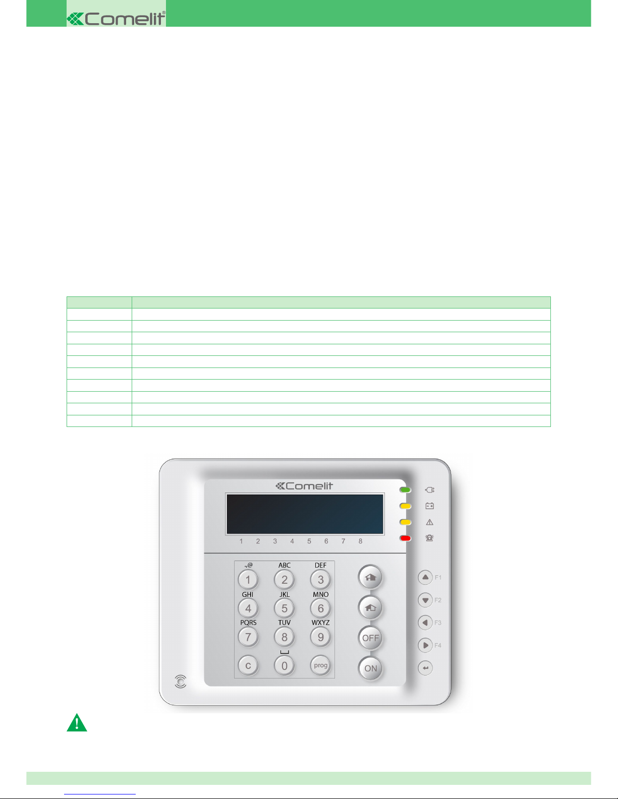
34
Modifying parameters/text with the keypad
When necessary, it is possible to confi gure the system and enter or modify data using one of the system keypads. Once you have selected the
item you want to modify, use the keys of the keypad that you are working on to enter the new data.
Navigating the menu: to navigate the menus displayed by the keypad, use the navigation keys located on the right-hand side of the keypad and
identifi ed by a black triangular arrow indicating the direction of movement (up, down, left and right). Once you have reached the data you intend
to modify, you need to press the confi rm key to go to the next level or enter the new data.
Modifying a numerical value: numerical values can be entered or modifi ed directly, simply by typing in the desired value, following the format
shown on the display, omitting non-numerical characters, but fi lling in all the numerical characters of the proposed format.
e.g. date DD-MM-YY must be entered as DDMMYY; 2 September 2012 will become 020912, without dashes but with a zero at the beginning to
fi ll the tens digit for the days.
e.g. Setpoint 1.14 is entered as 114, without the decimal point.
Modifying an alphanumeric string: once you have selected the string to modify (e.g. the description of a zone) the fi rst editable character will
start fl ashing. The characters can now be entered or replaced using the same writing mechanism as is available on cellphones with pushbutton
keypads. If you press the same key repeatedly, the proposed character will change according to a pre-set sequence. The table below shows the
sequence of characters available for each key.
If you press the C key when the character is fl ashing, you can exit the string without saving any changes.
To move around within the string, use the right and left navigation keys.
Pressing the C key while inside the string deletes the character to the left of the fl ashing character.
The new character, when necessary, will be entered to the left of the fl ashing character.
Press Confi rm to save the changes.
The table below shows the keys and the sequence of characters associated with each
Numerical Key Associated character sequence
1 . , : ; _ - # * ' @ 1
2 A B C a b c 2
3 D E F d e f 3
4 G H I g h i 4
5 J K L j k l 5
6 M N O m n o 6
7 P Q R S p q r s 7
8 T U V t u v 8
9 W X Y Z w x y z 9
0 (space) 0
The keypad package contains a removable transparent label to be affi xed during programming.
Incorrect application of the label may cause the keys to jam
Page 35

35
Setting the serial number of the keypad
At fi rst start-up, the keypad displays the message NOT CONNECTED. To enable the switchboard to recognise keypad number 1 (the only
keypad that can be recognised by the switchboard by default), proceed as follows:
1. Press the prog key on the keypad: the display will show the message 1 Confi g. Bus followed by two vertical arrows (up and down).
2. Press the confi rm key located immediately below the navigation keys
3. Enter the serial number of the fi rst keypad by typing the digits 001 in sequence, and then press confi rm
4. The display now shows the message SERIAL COM. Speed: with the proposal 38400.
5. Press confi rm.
Keypad number one will now be taken in charge by the switchboard and can be used for activating, deactivating and confi guring the system.
Activating and deactivating the system
To activate the alarm system completely, proceed as follows:
1. From the keypad, enter a valid user code (the default setting is 111111) and then press the ON key
2. The keypad asks for confi rmation: “TOTAL ACTIVATION?”
3. Press the Confi rm key to confi rm.
4. The keypad confi rms the action with the message: “ACTIVATED”
To activate the system partially or to run a scenario, proceed as follows:
1. From the keypad, enter a valid user code (default 111111) followed by either the Partial 1 key or the Partial 2 key.
2. If necessary, use the up and down navigation keys to select a different scenario from the proposed scenario, and then press Confi rm.
3. The keypad confi rms the action with the message: “ACTIVATED”
To deactivate the alarm system completely, proceed as follows:
1. From the keypad, enter a valid user code (the default setting is 111111) and then press the OFF key.
2. The keypad confi rms the action with the message: “DEACTIVATED”
3. Deactivation will also deactivate any alarms in progress within a few seconds.
Muting an alarm with the system deactivated
To mute an alarm with the system deactivated, proceed as follows:
1. From the keypad, enter a valid user code (default 111111).
2. Once the code has been recognised, press the Prog key until the message “DONE” appears on the screen.
3. This will mute the alarm.
Going into programming mode as a User
To go into programming mode as a user, proceed as follows:
1. From the keypad, enter a valid user code (default 111111)
2. Press Prog
3. The fi rst line of the display will show the message “System Mgmt.” indicating that you can now modify the system options
Going into programming mode as an Installer (installer code authorisation)
The installer code must be authorised by the user, so the procedure is as follows:
1. Go into programming mode as a user (see previous paragraph)
2. Using the navigation keys (up and down), select the “COMMANDS” menu on the second line of the display, and press Confi rm: the message
“GENERATE COMMAND” will appear on the fi rst line of the display
3. Using the navigation keys (up and down), select “AUTH. INSTALLER?” on the second line, and press Confi rm: the message “DONE” will
appear on the display
4. Press C until you have exited the menus completely (i.e. until the date and time are displayed on the keypad)
5. From the keypad, enter a valid installer code (default master code 001961).
6. Press Prog
7. The fi rst and second lines of the display will show the messages “Main Menu” and “Parameter Mgmt.” indicating that you can now display or
modify the system options
8. From this position, you can use the navigation keys to select either the “System Mgmt.” menu, which corresponds to the user menu, or the
“Parameter Prog.” menu, which is reserved for the installer
9. Press the Confi rm key to enter the respective submenus
Page 36

36
Acquiring an RFID key code from the keypad
1. From the keypad, enter a valid installer code (default master code 001961).
2. Press Prog
3. The fi rst and second lines of the display will show the messages “Main Menu” and “Parameter Prog.” respectively, indicating that you can now
modify the system options
4. Press the Confi rm key to enter the respective submenus
5. Using the navigation keys (up and down) select “ProximityKeys” submenu. Press Confi rm
6. The display will show the message “Key 1” and below it, the parameter that you can modify, namely “Description”
7. Using the navigation keys (left and right), select the number of the key you intend to acquire.
8. Press Confi rm if you intend to change the description, then confi rm to make the change or press C to leave the description as it is
9. Using the navigation keys (up and down), select the "Acquire" submenu. Still using the navigation keys, select the type of peripheral from
which you intend to acquire the key code and its bus address, then press Confi rm again
10. The display will show the message “Acq. Key: In progress...”
11. Bring the key close to the RFID reader: the message will change from "In progress..." to "Acquired"
12. Press Confi rm: the display will show a description of the colour of the key's plastic housing
13. Press Confi rm again to associate the key to the desired user.
14. Once you have fi nished making changes from the keypad, remember to transfer them to the PC by means of the Comelit alarm switchboards
confi guration programme.
Changing the date and time
√ To change the date and time from the keypad, you need to go into programming mode.
1. Go into programming mode as an installer (see relevant paragraph).
2. Using the navigation keys, select “System Mgmt.”, then continue as a user.
As installer:
1. Go into programming mode as a user (see relevant paragraph).
2. Using the navigation keys (up and down), select the “Options” menu on the second line of the display, and press Confi rm.
3. Using the navigation keys (up and down), select the “Change date/time” option on the second line, and press Confi rm.
4. The fi rst line will show DD-MM-YY (day, month and year) and the second line will display the date set on the switchboard.
5. Enter the date using the number keys (e.g. 1 September 2012 becomes 010912), then confi rm.
6. The fi rst line of the display now shows HH-MM (hours and minutes) and the second line shows the time set on the switchboard.
7. Enter the time in the format displayed (e.g. 1.15 pm becomes 1315), then confi rm.
8. This done, the display will show the message PARAMETER CHANGED.
9. Press C to go up one level in the menu, or C repeatedly until the date and time appear on the keypad.
As user:
Acquiring a radio sensor code from the keypad
1. Insert the battery in the sensor concerned and wait until the LED stops fl ashing. This applies to both magnetic contacts (REED) and infrared detectors
(PIR)
2. From the keypad, enter a valid installer code (default master code 001961).
3. Press Prog
4. The fi rst and second lines of the display will show the messages “Main Menu” and “Parameter Prog.” respectively, indicating that you can now modify
the system options
5. Press the Confi rm key to enter the respective submenus
6. Using the navigation keys (up and down), select “Radio Zones” submenu. Press Confi rm
7. The display will show the message “Radio Zone 1” and below it, the parameter that you can modify, namely “Description”
8. Using the navigation keys (left and right), select the position in which you intend to acquire the sensor
9. Using the navigation keys (up and down), select “Acquisition” and press Confi rm The display will show the message “Acq. Radio Zone: In progress...”
10. Now press and release the tamper button on the sensor
11. If acquisition is successful, the display will show the type of sensor (REED or PIR) and the unique code number of the sensor.
12. If acquisition fails because the sensor is already saved on the switchboard, the display will show the message “Acq. failed Dev. Duplicated” In this
case, it is preferable to acquire the parameters from a PC using the confi guration software, in order to check the programmed sensors, the acquired
codes and their parameters. This will make it easier to correct any confi guration errors.
13. Once you have fi nished making changes from the keypad, remember to transfer them to the PC by means of the Comelit alarm switchboards
confi guration programme.
Page 37

37
Acquiring a radio control code from the keypad
1. Press buttons n° 2 and 3 simultaneously until the radio control LEDs start fl ashing autonomously, then release the buttons and wait for the
LEDs to go off. Should this not happen within about ten seconds (e.g. with a new radio control) move onto the next point
2. From the keypad, enter a valid installer code (default master code 001961).
3. Press Prog
4. The fi rst and second lines of the display will show the messages “Main Menu” and “Parameter Prog.” respectively, indicating that you can now
modify the system options
5. Press the Confi rm key to enter the respective submenus
6. Using the navigation keys (up and down), select the “Radio Controls” submenu. Press Confi rm
7. The display will show the message “Radio Control 1” and below it, the parameter that you can modify, namely “Description”
8. Using the navigation keys (left and right), select the position in which you intend to acquire the radio control
9. Using the navigation keys (up and down), select “Acquisition” and press Confi rm The display will show the message “Acq. Radio Tel.: In
progress...”
10. Press buttons 3 and 4 simultaneously until the radio control LEDs start fl ashing, then release the buttons.
11. If acquisition is successful, the display will show the message “DEV. PENDANT” and the unique code number of the radio control.
12. Once you have fi nished making changes from the keypad, remember to transfer them to the PC by means of the Comelit alarm switchboards
confi guration programme.
Acquiring a siren code from the keypad
1. Disconnect the siren battery, if connected, and disconnect the audio from its connector. If the audio is already disconnected, connect it briefl y
to discharge the capacitors in the circuit and ensure subsequent clean switch-on
2. From the keypad, enter a valid installer code (default master code 001961).
3. Press Prog
4. The fi rst and second lines of the display will show the messages “Main Menu” and “Parameter Prog.” respectively, indicating that you can now
modify the system options
5. Press the Confi rm key to enter the respective submenus
6. Using the navigation keys (up and down) select the “Radio Outputs” submenu. Press Confi rm
7. The display will show the message “Output 1” and below it, the parameter that you can modify, namely“Description”
8. Using the navigation keys (left and right) select the position in which you intend to acquire the radio control
9. Using the navigation keys (up and down) select “Acquisition”.
10. Press and hold the siren's LEARN button, which is located near the connection strip for the confi guration jumpers, and connect the battery.
Hold the LEARN button down until the siren fl asher starts fl ashing quickly, then release the button
11. Wait until the fl asher starts fl ashing more slowly
12. Now press Confi rm on the keypad. The display will show the message “Acq. Radio Tel.: In progress...”
13. After about fi fteen seconds, the result of the acquisition will appear on the display
14. Once you have fi nished making changes from the keypad, remember to transfer them to the PC by means of the Comelit alarm switchboards
confi guration programme.
Exiting programming mode
To exit programming mode, simply press C until you have exited the menus completely, i.e. until the date and time are displayed on the keypad.
Restoring factory settings
You can reset the switchboard confi guration at two levels: level one, defi ned as Partial, and level two, defi ned as Total.
A partial reset is confi ned to recovering the switchboard codes, thereby making it possible to restore a system from which all the necessary codes
for use and management have been lost.
A total reset, by contrast, reconfi gures the switchboard card to its default settings, in such a way that it can be re-used as though newly unpacked
from its packaging. Total resets can be performed only via the confi guration software, provided you know both a user code and an installer code.
It may be necessary to perform a partial reset to recover the necessary codes.
The total reset process is described in the procedures set down in the system confi guration manual.
Partial Reset (code recovery)
A partial reset can be performed in hardware mode only.
To perform a partial reset to recover the default master installer and user codes, proceed as follows:
1. Switch off all power to the switchboard card
2. Insert a jumper on connector JP6
3. Power up the control panel
4. Wait until LED DL3 starts fl ashing at about 1 fl ash per second
5. Remove the jumper from JP6
6. The codes are now restored to their factory settings
Page 38

38
Switchboard electrical specifi cations
Rated supply voltage 230V~ ± 10% - 50Hz ± 10% 25VA
Consumption from mains 230V~
(power supply unit, switchboard and battery only)
0,3 A
Switchboard PSU output voltage 13.8V DC ± 5% 1.5A max.
Battery predisposition 12V 7Ah max.
Operating temperature +5°C to +40°C, RH max 90%
Tamper detection circuit Double balance, closed on termination - 1800 ohm (2 resistors)
Switchboard current consumption @13.8V DC,
with message module and IP module active but not connected and GSM module not in
transmission
180mA
Keypad current consumption @13.8V DC,
1) LEDs and LCD OFF 2) LEDs and LCD ON
1) 30mA
2) 70mA
Keypad current consumption with RFID reader @13.8V DC,
1) LEDs and LCD OFF 2) LEDs and LCD ON
1) 35mA
2) 75mA
I/O expansion module current consumption in standby @13.8V DC 25mA
Bus RFID reader current consumption @13.8V DC 1) in standby, 2) LEDs ON
3) reading / writing
1) 19mA
2) 24mA
3) 45 / 55mA
Bus radio receiver current consumption @13.8V DC
1) idle 2) idle and LEDs ON 3) reading key and LEDs ON
1) 12mA
2) 18mA
3) 45mA - 55mA max
Value of end-of-line resistors in double balance 1800 ohm (2 resistors per circuit)
Value of end-of-line resistors in triple balance (e.g. alarm + fault) 1800 ohm (2 resistors per circuit, plus one 3300 ohm resistor)
RS485 cable connection
V+ BUS (Power supply positive)
V- (Power supply negative)
A (Data bus signal A)
B (Data bus signal B)
Maximum length of data cable 1000m
Relay output 1 potential-free exchange, 3A @ 24VDC
TC outputs Confi gurable as OC or OE, limited to 100mA
Setting the control panel to Service Status
Exiting Service Status
This function allows the installer to work on the VEDO System with complete peace of mind, with the siren, PSTN part, GSM part and
email all “silenced”.
The control panel is working and can be programmed (via Safe Manager) but does not generate any Alarm event.
1. From the keypad, enter a valid user code (default 111111)
2. Press Prog
3. The fi rst line of the display will show the message “System, Mgmt.” indicating that you can now modify the system options
4. Using the navigation keys (up and down), select the “COMMANDS” menu on the second line of the display, and press Confi rm: the message
“GENERATE COMMAND” will appear on the fi rst line of the display
5. Using the navigation keys (up and down), select “AUTH. INSTALLER?” on the second line, and press Confi rm: the message “DONE” will
appear on the display
6. Press C until you have exited the menus completely (i.e. until the date and time are displayed on the keypad)
7. Enter a valid user code (default 111111) or a valid installer code (default Master code 001961).
8. Press Prog
9. Open the control panel cover
10. Insert jumper JP7
1. Remove jumper JP7.
2. Enter a valid user code (default 111111) or a valid installer code (default Master code 001961).
3. Press Prog
4. Close the control panel cover
5. Press C until you have exited the menus completely
» The control panel will remain in service while jumper JP7 remains inserted. The keypad display will show "SCHEDULED MAINTENANCE!" or
"N" across all areas.
Page 39
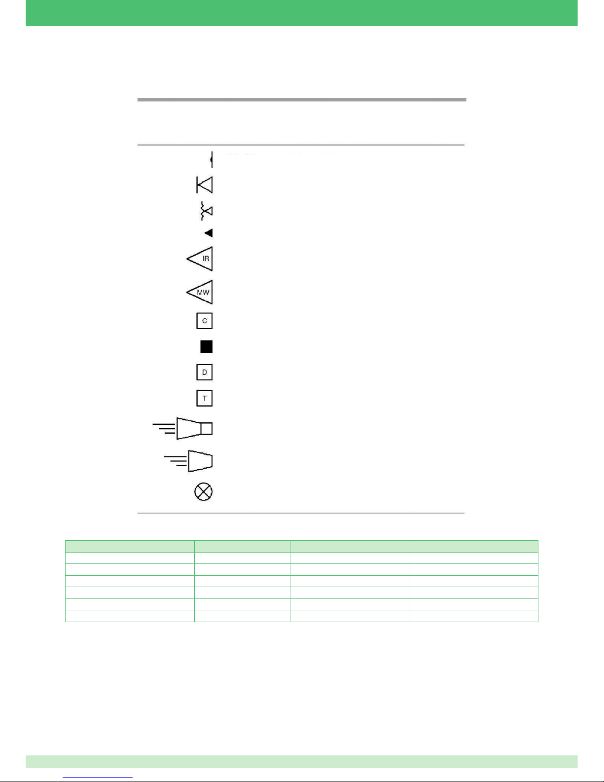
39
APPENDICES
Appendix 1: offi cial symbol conventions for anti-intrusion systems
Appendix 2: shielded cable conductor resistance table
Input and signal connections
For the bus signals (A and B) you can use a conductor with section of 0.22 mm2.
The resistance shown in the table refers to a single conductor, so if, for example, you want to evaluate the additional resistance introduced by
the cable for a run of 100m, you need to double the length. You therefore need to consider 200m total length of conductor (100m outward to the
point and 100m return from the point).
In the case of a contact connected to the switchboard by a run of 100m of cable with “n” structure for 0.22 mm
2
, the total resistance added by the
cable becomes 17 ohm. For connection to an alarm input, 17 ohm does not generally compromise the performance of the system.
SHIELDED ALARM CABLE FORMATION CONDUCTOR DIAMETER [mm] MINIMUM RESISTANCE OHM PER 1 METRE MINIMUM RESISTANCE OHM PER 100 METRES
n X 0.22 mm
2
0.50 0.085 8.5
n X 0.50 mm
2
0.80 0.032 3.2
n X 0.75 mm
2
0.90 0.026 2.6
n X 1 mm
2
1 0.020 2
n X 1.5 mm
2
1.28 0.013 1.3
n X 2.5 mm
2
1.65 0.008 0.82
Legend
Magnetic contact detector
Inertial vibration detector
Microphone glass break detector
Microphone detector
Passive infrared detector
Microwave detector
Switchboard
Control component with electronic key
Message dispatcher on dedicated line
Message dispatcher on switched line
Self-powered audible alarm device
Audible alarm device
Illuminating alarm device
Page 40
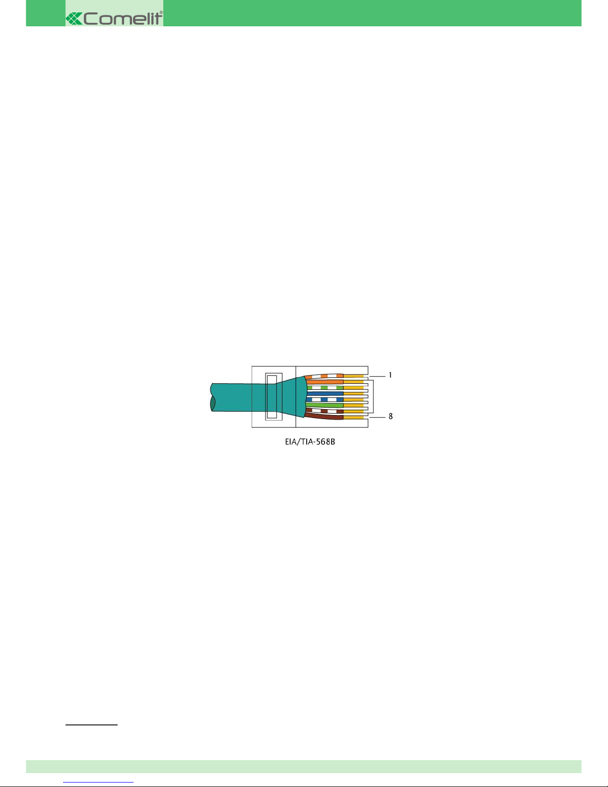
40
Power supply connections
In the above circumstances, the resistance can be overlooked in the majority of cases. More care must be taken, however, if the cable has to
carry power: in this case, the resistance could cause a signifi cant drop for the purposes of correct operation of the device you intend to power.
Supposing we have a run of 100m of cable powering a device with consumption of 100mA. Using Ohm's Law
1
, let us analyse the voltage drops
for a range of sections:
0.22 mm
2
: V=R*I = 17*0.1 = 1.7V
0.50 mm
2
: V=R*I = 6.4*0.1 = 0.64V
0.75 mm
2
: V=R*I = 5.2*0.1 = 0.52V
1 mm
2
: V=R*I = 4*0.1 = 0.4V
This is why it is important to size the power supply conductors correctly.
Appendix 3: data network connection cable
To connect the IP module of the S68 switchboard to a data network, you need to go through a hub or a network switch. The switchboard will be
connected by means of a network cable in straight confi guration. In many cases, it will be possible to buy a standard cable of suitable length, but
when this is not possible, you will need to make the connection autonomously.
This is done using UTP CAT5 cable or higher.
The cable will be terminated at both ends with RJ45 plugs with the aid of a specifi c crimp tool. Both RJ45 plugs must be wired in the same
sequence as shown in the fi gure.
The conductor colours shown in the fi gure must be rigorously observed. Non-conformance with the colours may cause the connection to work
intermittently or not at all.
Procedure:
1. Remove about 5 cm of jacket from the cable so as to make the 4 pairs of wire accessible
2. Separate the conductors in the pairs
3. Stretch the conductors out so as to straighten them, and place them in the order shown in the fi gure
4. Adjust the length of the conductors to about 12mm
5. Insert the conductors as shown in the fi gure (the connector is illustrated as seen from the side)
1 V = R * I. The estimated drop in Volts is equal to the total resistance of the circuit, expressed in Ohms, multiplied by the circulating
current I, expressed in amps.
2° edition 07/2014 code 2G40001178
 Loading...