

Page 1
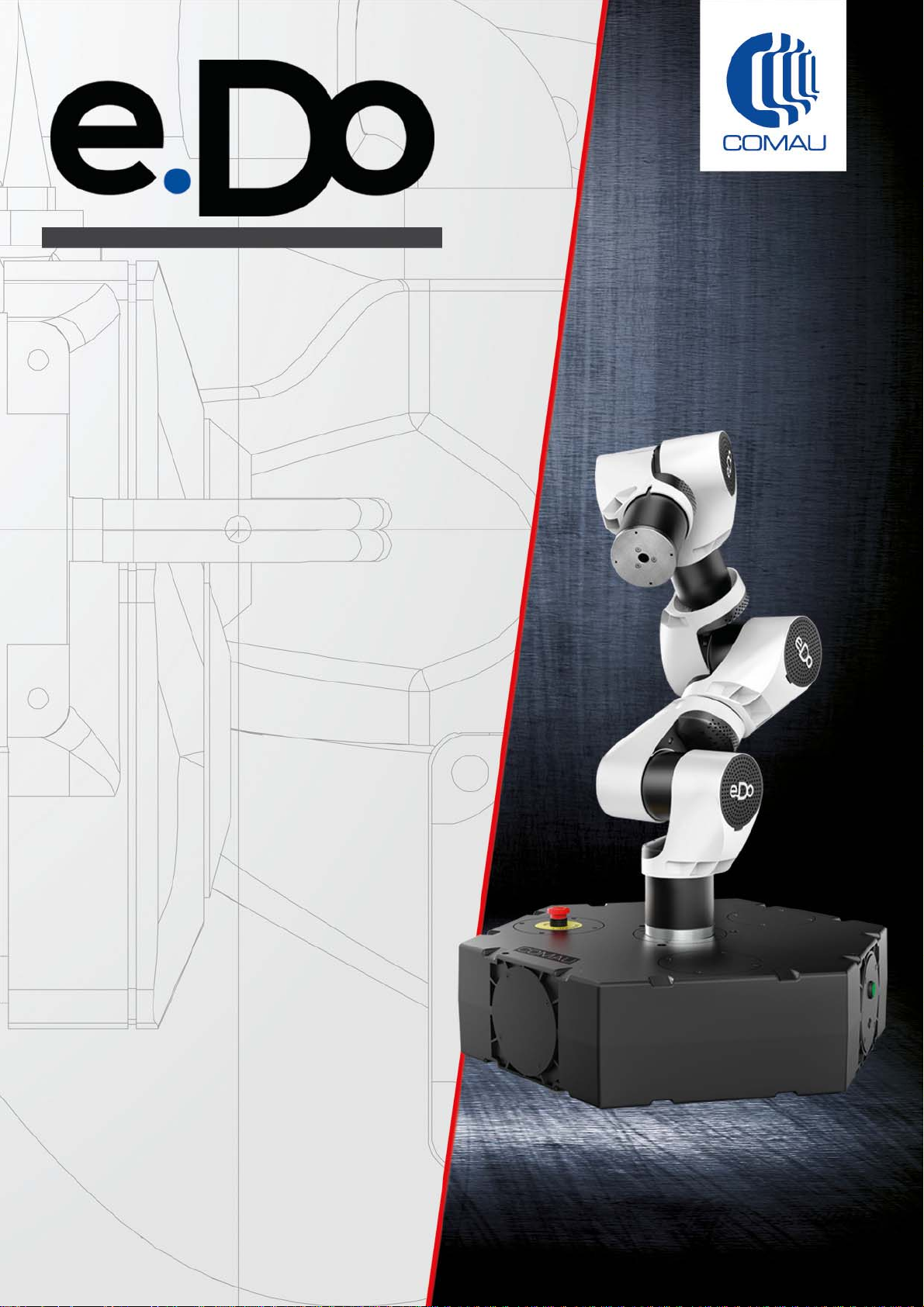
e.DO Robot
Rel. 00 - Versions
- 6 central axes
- 6 side axes
- 6 central axes, with Gripper
- 6 side axes, with Gripper
User Manual
- Robot description
- Removal of packaging and installation
- Connection and first power-up
- Tablet configuration
- Instructions for use of the application
- Instructions for cleaning and periodic checks.
CR00758210-en_00/2019.04
Page 2

The contents of this handbook are the property of COMAU S.p.A.
Any reproduction, even partial, is prohibited without prior written authorization from COMAU S.p.A.
COMAU S.p.A. reserves the right to modify, without notice, the features of the product presented in this handbook.
Copyright © 2008-2019 by COMAU - Published 04/2019
Page 3

Comau Robotics Product Instruction
SUMMARY
SUMMARY
TO WHOM IS THIS HANDBOOK ADDRESSED? . . . . . . . . . . . . . . . . . . . . . . . . . . . . .6
PREFACE . . . . . . . . . . . . . . . . . . . . . . . . . . . . . . . . . . . . . . . . . . . . . . . . . . . . . . . . . . . .7
Documentation storage . . . . . . . . . . . . . . . . . . . . . . . . . . . . . . . . . . . . . . . . . . . . . . . . . . . . . . . . 8
Limits on the handbook contents . . . . . . . . . . . . . . . . . . . . . . . . . . . . . . . . . . . . . . . . . . . . . . . . . 8
Symbols used in the handbook . . . . . . . . . . . . . . . . . . . . . . . . . . . . . . . . . . . . . . . . . . . . . . . . . . 8
MODIFICATION HISTORY . . . . . . . . . . . . . . . . . . . . . . . . . . . . . . . . . . . . . . . . . . . . . . .9
1. SAFETY REQUIREMENTS . . . . . . . . . . . . . . . . . . . . . . . . . . . . . . . . . . . . . . . . . . . . ...10
2. ROBOT GENERAL DESCRIPTION . . . . . . . . . . . . . . . . . . . . . . . . . . . . . . . . . . . . . ...11
Introduction . . . . . . . . . . . . . . . . . . . . . . . . . . . . . . . . . . . . . . . . . . . . . . . . . . . . . . . . . . . . . . . . 11
Description of the main parts that make up the Robot. . . . . . . . . . . . . . . . . . . . . . . . . . . . . . . . 12
Robot axis identification. . . . . . . . . . . . . . . . . . . . . . . . . . . . . . . . . . . . . . . . . . . . . . . . . . . . . . . 14
Intended use . . . . . . . . . . . . . . . . . . . . . . . . . . . . . . . . . . . . . . . . . . . . . . . . . . . . . . . . . . . . . . . 14
Incorrect, unintended and not allowed uses . . . . . . . . . . . . . . . . . . . . . . . . . . . . . . . . . . . . . . . 15
Robot certification . . . . . . . . . . . . . . . . . . . . . . . . . . . . . . . . . . . . . . . . . . . . . . . . . . . . . . . . . . . 15
3. ROBOT HANDLING, ASSEMBLY AND FIRST START . . . . . . . . . . . . . . . . . . . . . . ...18
How to handle the Robot inside the packaging . . . . . . . . . . . . . . . . . . . . . . . . . . . . . . . . . . . . . 18
Removal of the Robot from the packaging. . . . . . . . . . . . . . . . . . . . . . . . . . . . . . . . . . . . . . . . . 19
Robot positioning on supporting surface . . . . . . . . . . . . . . . . . . . . . . . . . . . . . . . . . . . . . . . . . . 20
Robot connection. . . . . . . . . . . . . . . . . . . . . . . . . . . . . . . . . . . . . . . . . . . . . . . . . . . . . . . . . . . . 21
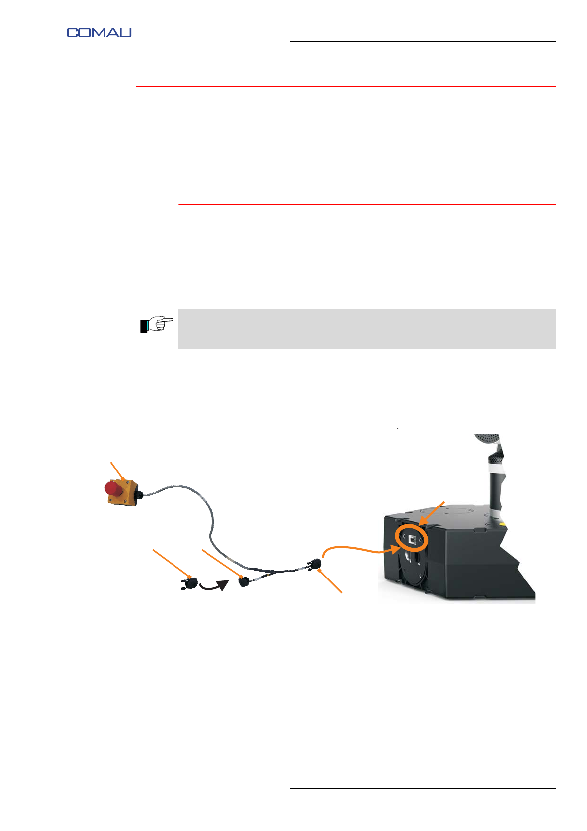
Emergency stop push-button connection. . . . . . . . . . . . . . . . . . . . . . . . . . . . . . . . . . . . . . . . 21
Connection to the electric power supply mains . . . . . . . . . . . . . . . . . . . . . . . . . . . . . . . . . . . 22
First power-up of the Robot . . . . . . . . . . . . . . . . . . . . . . . . . . . . . . . . . . . . . . . . . . . . . . . . . . . . 23
4. CONFIGURATION AND CONNECTION OF THE COMMAND INTERFACE (TABLET) .
..24
Requirements. . . . . . . . . . . . . . . . . . . . . . . . . . . . . . . . . . . . . . . . . . . . . . . . . . . . . . . . . . . . . . . 24
Download of the app . . . . . . . . . . . . . . . . . . . . . . . . . . . . . . . . . . . . . . . . . . . . . . . . . . . . . . . . . 25
Installation of the app . . . . . . . . . . . . . . . . . . . . . . . . . . . . . . . . . . . . . . . . . . . . . . . . . . . . . . . . . 26
3
Page 4

Comau Robotics Product Instruction
SUMMARY
Running of the app and connection to e.DO . . . . . . . . . . . . . . . . . . . . . . . . . . . . . . . . . . . . . . . 27
Selection of interface language . . . . . . . . . . . . . . . . . . . . . . . . . . . . . . . . . . . . . . . . . . . . . . . 28
Connection to e.DO . . . . . . . . . . . . . . . . . . . . . . . . . . . . . . . . . . . . . . . . . . . . . . . . . . . . . . . . 29
e.DO configuration . . . . . . . . . . . . . . . . . . . . . . . . . . . . . . . . . . . . . . . . . . . . . . . . . . . . . . . . . . . 30
e.DO configuration selection . . . . . . . . . . . . . . . . . . . . . . . . . . . . . . . . . . . . . . . . . . . . . . . . . 30
e.DO calibration . . . . . . . . . . . . . . . . . . . . . . . . . . . . . . . . . . . . . . . . . . . . . . . . . . . . . . . . . . . 31
5. USE OF THE “E.DO” APP. . . . . . . . . . . . . . . . . . . . . . . . . . . . . . . . . . . . . . . . . . . . . ..33
How to move e.DO through the app . . . . . . . . . . . . . . . . . . . . . . . . . . . . . . . . . . . . . . . . . . . . . 33
Movement in Cartesian mode . . . . . . . . . . . . . . . . . . . . . . . . . . . . . . . . . . . . . . . . . . . . . . . . 34
Movement in Joints mode . . . . . . . . . . . . . . . . . . . . . . . . . . . . . . . . . . . . . . . . . . . . . . . . . . . 35
Movement in Input mode . . . . . . . . . . . . . . . . . . . . . . . . . . . . . . . . . . . . . . . . . . . . . . . . . . . . 37
How to create a movement program . . . . . . . . . . . . . . . . . . . . . . . . . . . . . . . . . . . . . . . . . . . . . 39
Creating a movement program through “Projects” page . . . . . . . . . . . . . . . . . . . . . . . . . . . . 39
Creating a movement program through “Blockly”. . . . . . . . . . . . . . . . . . . . . . . . . . . . . . . . . . 42
“Settings” Menu . . . . . . . . . . . . . . . . . . . . . . . . . . . . . . . . . . . . . . . . . . . . . . . . . . . . . . . . . . . . . 45
LAN Configuration . . . . . . . . . . . . . . . . . . . . . . . . . . . . . . . . . . . . . . . . . . . . . . . . . . . . . . . . . 46
Wi-Fi Configuration. . . . . . . . . . . . . . . . . . . . . . . . . . . . . . . . . . . . . . . . . . . . . . . . . . . . . . . . . 47
Blockly . . . . . . . . . . . . . . . . . . . . . . . . . . . . . . . . . . . . . . . . . . . . . . . . . . . . . . . . . . . . . . . . . . 48
Control switch. . . . . . . . . . . . . . . . . . . . . . . . . . . . . . . . . . . . . . . . . . . . . . . . . . . . . . . . . . . . . 49
Language . . . . . . . . . . . . . . . . . . . . . . . . . . . . . . . . . . . . . . . . . . . . . . . . . . . . . . . . . . . . . . . . 49
“About” Menu . . . . . . . . . . . . . . . . . . . . . . . . . . . . . . . . . . . . . . . . . . . . . . . . . . . . . . . . . . . . . . . 50
6. AVAILABLE OPTIONS FOR E.DO . . . . . . . . . . . . . . . . . . . . . . . . . . . . . . . . . . . . . . ..51
e.DO Gripper . . . . . . . . . . . . . . . . . . . . . . . . . . . . . . . . . . . . . . . . . . . . . . . . . . . . . . . . . . . . . . . 52
What is the e.DO Gripper for? . . . . . . . . . . . . . . . . . . . . . . . . . . . . . . . . . . . . . . . . . . . . . . . . 52
e.DO Gripper technical features. . . . . . . . . . . . . . . . . . . . . . . . . . . . . . . . . . . . . . . . . . . . . . . 53
Safety requirements for e.DO Gripper use. . . . . . . . . . . . . . . . . . . . . . . . . . . . . . . . . . . . . . . 53
e.DO Gripper diagrams and drawings . . . . . . . . . . . . . . . . . . . . . . . . . . . . . . . . . . . . . . . . . . 53
How to mount the e.DO Gripper on the e.DO Robot . . . . . . . . . . . . . . . . . . . . . . . . . . . . . . . 54
e.DO Marker Holder . . . . . . . . . . . . . . . . . . . . . . . . . . . . . . . . . . . . . . . . . . . . . . . . . . . . . . . . . . 55
What is the e.DO Marker Holder for? . . . . . . . . . . . . . . . . . . . . . . . . . . . . . . . . . . . . . . . . . . . 55
Safety requirements for e.DO Marker Holder use . . . . . . . . . . . . . . . . . . . . . . . . . . . . . . . . . 56
e.DO Marker Holder diagrams and drawings . . . . . . . . . . . . . . . . . . . . . . . . . . . . . . . . . . . . . 56
How to mount the e.DO Marker Holder on the e.DO Robot. . . . . . . . . . . . . . . . . . . . . . . . . . 56
How to fix the marker on the e.DO Marker Holder . . . . . . . . . . . . . . . . . . . . . . . . . . . . . . . . . 57
7. E.DO CLEANING INSTRUCTIONS AND PERIODIC CHECKS. . . . . . . . . . . . . . . . . ..58
Periodic checks . . . . . . . . . . . . . . . . . . . . . . . . . . . . . . . . . . . . . . . . . . . . . . . . . . . . . . . . . . . . . 59
Check the presence and conservation state of the warning signs and labels . . . . . . . . . . . . 59
Check the correct fixing of the e.DO parts . . . . . . . . . . . . . . . . . . . . . . . . . . . . . . . . . . . . . . . 60
Check the correct functioning of emergency push-buttons . . . . . . . . . . . . . . . . . . . . . . . . . . 60
e.DO cleaning . . . . . . . . . . . . . . . . . . . . . . . . . . . . . . . . . . . . . . . . . . . . . . . . . . . . . . . . . . . . . . 61
4
Page 5

Comau Robotics Product Instruction
SUMMARY
8. GENERAL TECHNICAL FEATURES OF THE E.DO ROBOT . . . . . . . . . . . . . . . . . ...62
9. WARRANTY TERMS AND CONDITIONS. . . . . . . . . . . . . . . . . . . . . . . . . . . . . . . . . ...63
Warranty conditions for B2B (Business-to-Business) sale. . . . . . . . . . . . . . . . . . . . . . . . . . . . . 64
Warranty conditions for B2C (Business-to-Customer) sale . . . . . . . . . . . . . . . . . . . . . . . . . . . . 64
5
Page 6

Comau Robotics Product Instruction
TO WHOM IS THIS HANDBOOK ADDRESSED?
TO WHOM IS THIS HANDBOOK
ADDRESSED?
This handbook is addressed to users of e.DO.
It contains information (e.g. description of the Robot, removal of packaging and
installation, connection and first power-up, configuration of the tablet, Instructions for
use of the application, instructions for cleaning and periodic checks) essential for the
correct use of the Robot and the relative control app.
6
Page 7

PREFACE
This chapter contains:
– Documentation storage
– Limits on the handbook contents
– Symbols used in the handbook
– Modification History.
Comau Robotics Product Instruction
PREFACE
7
Page 8
Comau Robotics Product Instruction
PREFACE
Documentati on storage
All documents supplied with e.DO must be stored in the immediate vicinity of the area
in which e.DO is in use and kept available to all persons operating on the machine.
The documentation must be kept intact for the entire operational life of e.DO.
In case of lost or damage of this manual (also partial), require a new copy to the
manufacturer.
Limits on the handbook contents
The images included in the instructions handbook have the purpose to represent the
product
and can differ from what is actually visible on the system.
Symbols used in the handbook
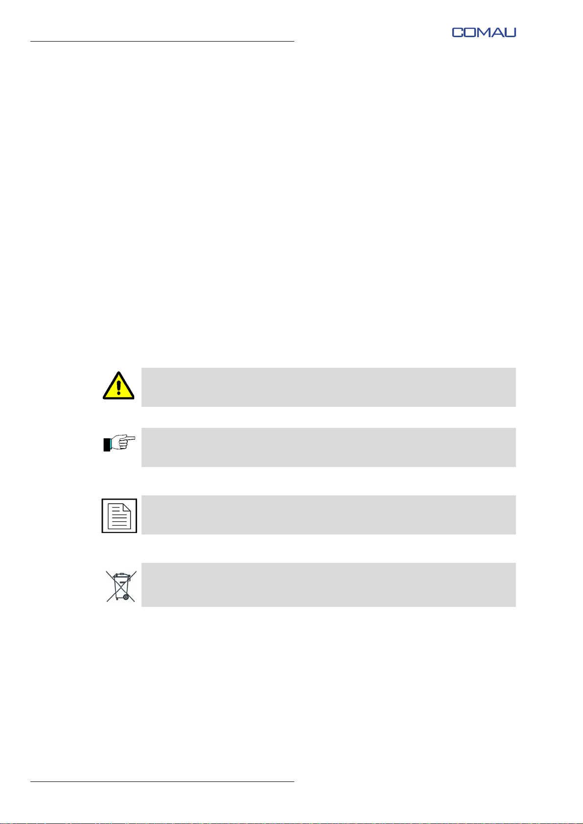
Below are indicated the symbols that represent: WARNING, CAUTION and NOTES and
their meaning.
This symbol indicates operating procedures, technical information and precautions that
if are not observed and/or correctly performed may cause injuries to the personnel.
This symbol indicates operating procedures, technical information and precautions that
if are not observed and/or correctly performed may cause damage to the equipment.
This symbol indicates operating procedures, technical information and precautions that
must be underlined.
The symbol draws the attention to materials disposal that is regulated by the WEEE
Directive.
8
Page 9
Comau Robotics Product Instruction
MODIFICATION HISTORY
MODIFICATION HISTORY
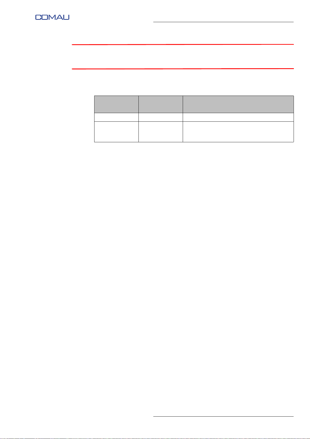
The following table shows the history of the Handbook release, with related changes /
improvements made.
Date
2019/03 00/2019.03 First release of the handbook
2019/04 00/2019.04 Improvement of paragraphs related to “Control
Edition of the
Handbook
Contents
Switch” on Desk Simulator.
Minor content improvements.
9
Page 10
Comau Robotics Product Instruction
SAFETY REQUIREMENTS
1.
SAFETY REQUIREMENTS
Carefully read this document before carrying out any operation on the Robot. Comau
will not be responsible for any damages or injuries caused by improper/unauthorized
installations, uses or operations carried out on the Robot.
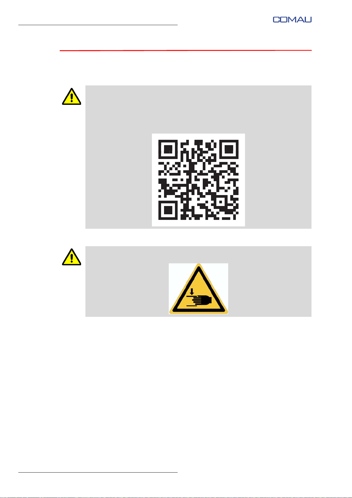
Before using or operating on the Robot, view the introductory video on safety aspects,
available online.
The video is accessible by scanning the following QR code:
During the use of the Robot, pay attention because a residual risk of pinching remains
on the axes 2, 3 and 5, identified by specific warning labels:
10
Page 11
Comau Robotics Product Instruction
ROBOT GENERAL DESCRIPTION
2.
ROBOT GENERAL DESCRIPTION
– Introduction
– Description of the main parts that make up the Robot
– Robot axis identification
– Intended use
– Incorrect, unintended and not allowed uses
– Robot certification
2.1 Introduction
e.DO Robot is a modular, multi-axis articulated (anthropomorphic with 6 degrees of
freedom) Personal Care Robot with an integrated open-source intelligence, specially
designed and built in order to be used in an educational environment, with the aim of
making learning, creation, exploration and programming more fun and interactive.
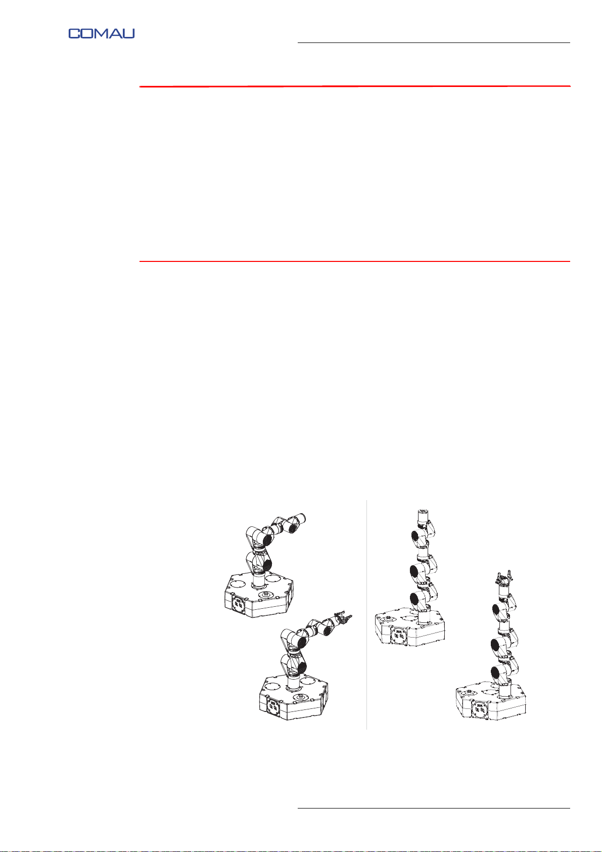
e.DO is available in different versions and configurations:
– e.DO with 6 central axes
– e.DO with 6 side axes
– e.DO with 6 central axes, with Gripper
– e.DO with 6 side axes, with Gripper
Fig. 2.1 - e.DO - overview
central e.DO side e.DO
11
Page 12
Comau Robotics Product Instruction
ROBOT GENERAL DESCRIPTION
2.2 Description of the main parts that make up the Robot
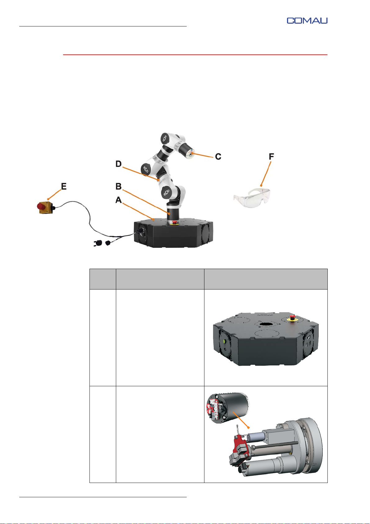
The Robot is characterized by a modular composition, obtained by assembling and
connecting the “smallest construction units” described below.
Fig. 2.2 - Identification of e.DO components
Tab. 2.1 - Description of the e.DO components
Ref.
Fig. 2.2
A
B
Name and description Image
Robot base
Robot basic structure
equipped with interface
devices (switch, buttons,
connectors) inside which the
Robot main power supply and
controller boards are installed.
Big joint
Unit consisting of joint board
(for motor control), motor,
encoder, gearbox, brake,
main shaft, support plate,
gears and output flange.
The big joint constitutes the
first 3 axes of the Robot (Ax.
1, Ax. 2 and Ax. 3).
12
Page 13
Comau Robotics Product Instruction
ROBOT GENERAL DESCRIPTION
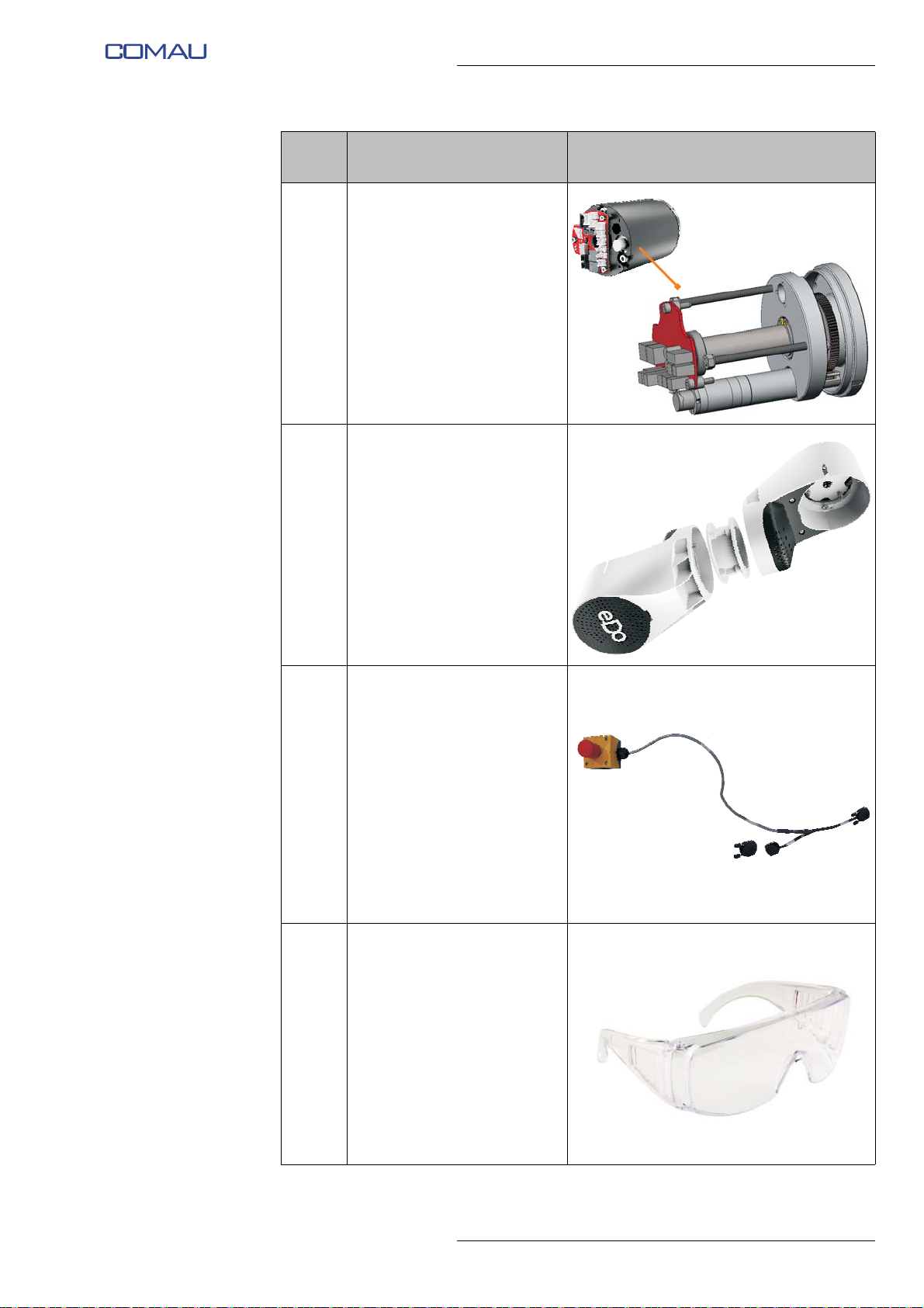
Ref.
Fig. 2.2
C
D
Name and description Image
Small joint
Unit consisting of joint board
(for motor control), motor,
encoder, gearbox, main shaft,
support plate, gears and
output flange.
The small joint constitutes the
remaining 3 axes of the Robot
(Ax. 4, Ax. 5 and Ax. 6).
Brackets and adapters
Assembly composed of
brackets and adapters, used
for physical connection
between the various joints.
Remote emergency
push-button
An additional emergency
push-button is available to be
positioned freely near the
Robot.
E
The cap connector to be used
in case of absence of
additional emergency
push-buttons and/or
interlocking devices
associated with guards is also
available.
Protective glasses
F
Protective equipment to wear
during the use of the Robot.
13
Page 14
Comau Robotics Product Instruction
Ax. 1Ax. 1
Ax. 2Ax. 2
Ax. 3Ax. 3
Ax. 5Ax. 5
Ax. 6Ax. 6
Ax. 4Ax. 4
ROBOT GENERAL DESCRIPTION
2.3 Robot axis identification
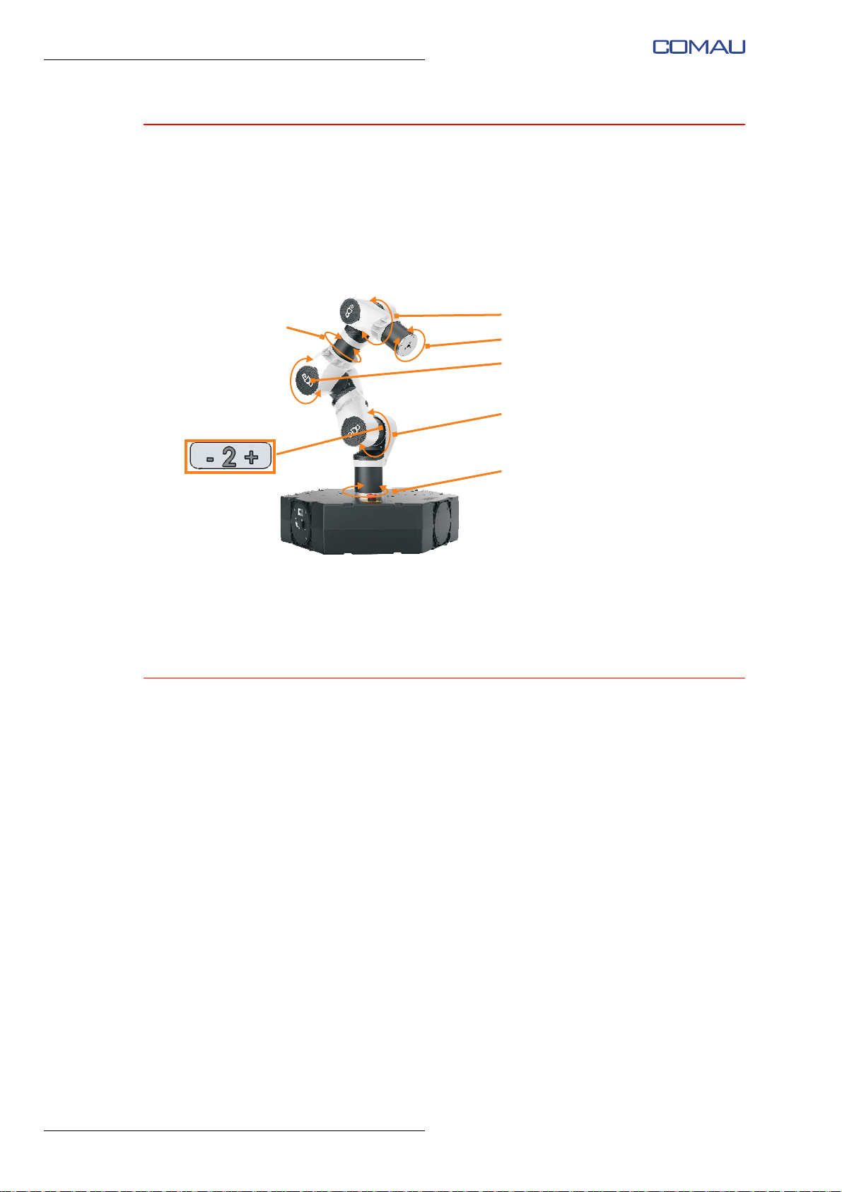
The Robot is equipped with 6 degrees of freedom (called axes), as shown in the
following figure.
Fig. 2.3 - Robot axis identification
6-axis e.DO
Each axis has the ability to rotate clockwise or counterclockwise; in order to facilitate
their identification, the direction of rotation of the individual axes is indicated by special
labels “+” / “-” affixed directly on the Robot structure.
2.4 Intended use
e.DO is suitable for use in schools / educational settings as an educational tool to
support the teaching of school subjects such as mathematics, geometry, technical
education and programming and finds various applications depending on the school of
use (elementary, middle, high schools, university, etc.).
It can be equipped with some optional devices to expand its functionalities (see details
in Chap.6. - Available options for e.DO).
The Robot and its optional devices can be used:
– by children of minimum age of 14 years (if minors, only in the presence of an adult);
in c
ase of use of the e.DO Robot in educational environments with children aged 8
or over, it is necessary to limit the activity of the children to interaction only, with
constant supervision of a trained and instructed adult and with the use of PPE for
eye protection;
– by persons with reduced physical, sensory or mental capabilities, or with lack of
exp
erience and knowledge, on conditions that they are under the supervision of an
adequately trained and informed adult, responsible for the safe use of the Robot
itself.
14
– The aforementioned persons must not play with the equipment, nor must they
per
form cleaning and routine maintenance operations.
Page 15

Comau Robotics Product Instruction
ROBOT GENERAL DESCRIPTION
2.5 Incorrect, unintended and not allowed uses
Methods of use other than those indicated in par. Intended use are considered as
incorrect, unintended and not allowed use.
In particular:
– do not use the Robot working with wet or damp hands or feet;
– do not use the Robot in dangerous environments (e.g. environments with potential
fire and/or explosion risks);
– do not suspend or fix objects or similar to the Robot structure during operation;
– do not make changes to the mechanical conformation of the Robot;
– do not use the Robot for handling / lifting of loads, items or potentially dangerous
objects (e.g. sharp objects or with sharp shapes) or in any case outside of what is
intended and allowed by the
Available options for e.DO.
2.6 Robot certification
The e.DO Robot is considered a “Machine” as defined in Article 2(a) of the Machinery
Directive 2006/42/EC and anthropomorphic “Personal Care Robot (type 1.1)” with 6
degrees of freedom as set out in the standard EN ISO 13482:2014.
The Robot complies with the requirements of the following Community Directives:
– DIRECTIVE 2006/42/EC OF THE EUROPEAN PARLIAMENT AND OF THE
COUNCIL of 17 May 2006 on machinery, and amending Directive 95/16/EC
(recast)
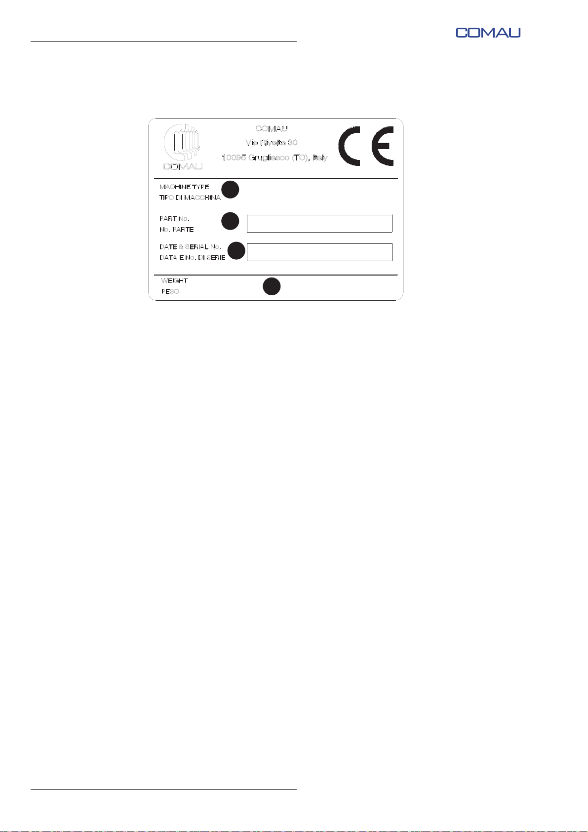
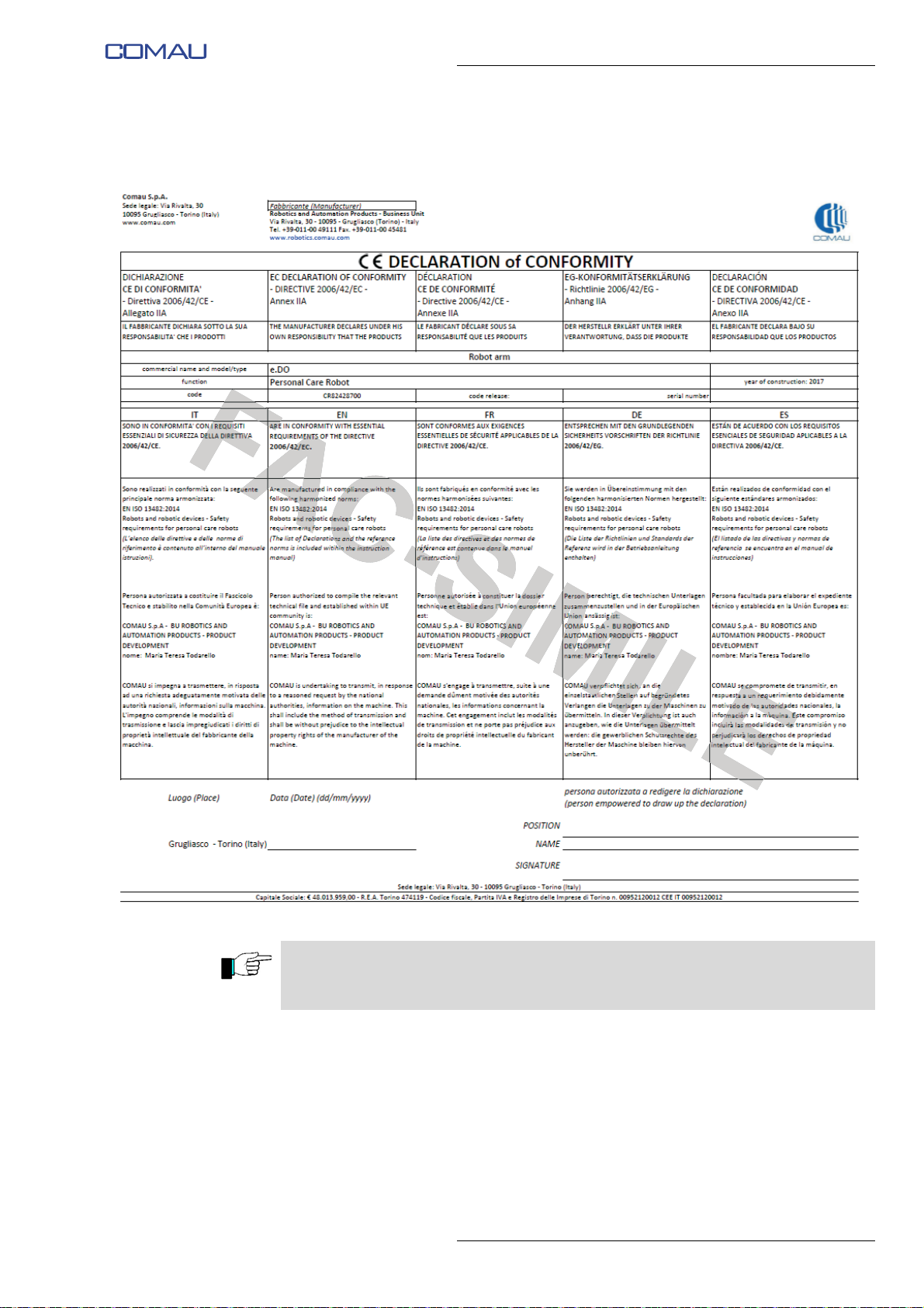
The following Fig. 2.4 and Fig. 2.5 show the plate with CE marking applied on the Robot
and an example of the EC Declaration of Conformity, respectively.
The original document is provided as an attachment thereto.
The following are the harmonized standards followed for the design and construction of
the Robot:
– EN ISO 13482: 2014 Robot and robotic devices – Safety requirements for personal
care Robots
– EN ISO 12100: 2010 Safety of machinery - General principles for design - Risk
assessment and risk reduction.
– EN ISO 13849-1: 2016 Safety of machinery – Safety related parts of control
systems – Part 1: General principles for design.
– EN 60204-1: 2006 Safety of machinery - Electrical equipment of machines. Part 1:
General requirements and subsequent amendments.
15
Page 16
Comau Robotics Product Instruction
xxx lb / xxx kg
REL. xxx
xxxx
xxxxxxxx
xxxxxxxx
A
B
C
D
ROBOT GENERAL DESCRIPTION
Fig. 2.4 - Plate with CE marking (facsimile)
– A: Machine name and release
– B: Product Part No.
– C: Date of issue and serial number
– D: Weight
16
Page 17
Comau Robotics Product Instruction
ROBOT GENERAL DESCRIPTION
Fig. 2.5 - CE Declaration of Conformity (facsimile)
Any unauthorized HW / SW modification and/or use of tools or tools other than those
listed and described in the chapter Available options for e.DO will give rise to forfeiture
of the CE certification.
17
Page 18

Comau Robotics Product Instruction
ROBOT HANDLING, ASSEMBLY AND FIRST START
3.
ROBOT HANDLING, ASSEMBLY AND FIRST
START
– How to handle the Robot inside the packaging
– Removal of the Robot from the packaging
– Robot positioning on supporting surface
– Robot connection
– First power-up of the Robot
3.1 How to handle the Robot inside the packaging
The e.DO Robot is packed inside a cardboard box.
The box is equipped with special handles to be used as gripping points for manual lifting
and handling.
Given the weight of the box, the manual handling must be carried out by adults.
18
Page 19
Comau Robotics Product Instruction
ROBOT HANDLING, ASSEMBLY AND FIRST START
3.2 Removal of the Robot from the packaging
Do not handle the Robot and perform the installation working with wet or damp hands
or feet.
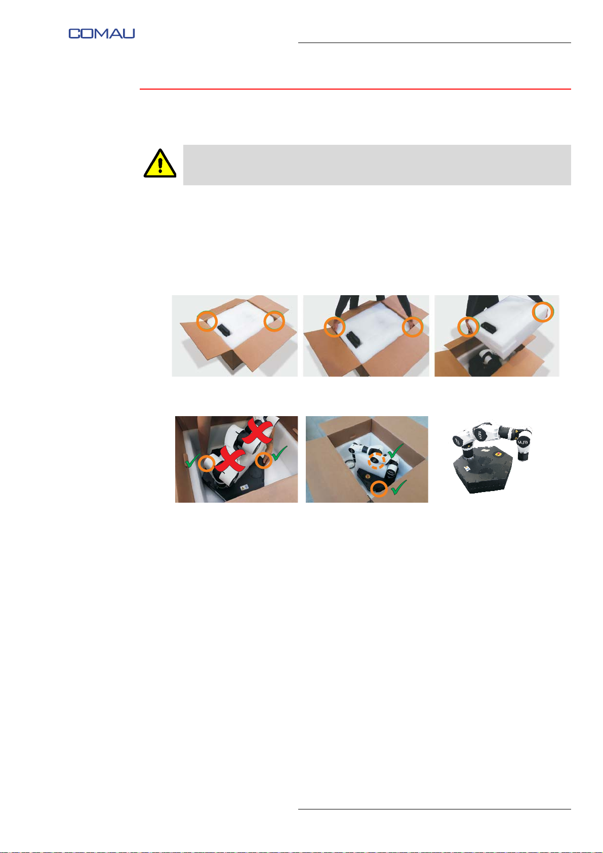
To remove the Robot from the box inside which it is packed and transported, proceed
as follows:
– open the box from the upper side, operating carefully to avoid damaging the
components inside the box;
– remove the upper layer of expanded polyethylene packaging using the 2 corners
shown in the figure as gripping points;
– remove e.DO by grasping it by the base as shown in the figure; do not grasp e.DO
by the rest of the structure to avoid possible damage;
– after removing the packaging, check that the Robot does not show signs of
damage during transport; if it does, do not install the Robot and contact the Comau
Service Centre (https://edo.cloud/support-and-contacts/);
– verify that all the components of the Robot are correctly and permanently fixed and
that there are no wobbly parts or elements;
– check that the power supply and cables provided are intact and do not show
damage, cuts, fraying, etc.
19
Page 20
Comau Robotics Product Instruction
ROBOT HANDLING, ASSEMBLY AND FIRST START
3.3 Robot positioning on supporting surface
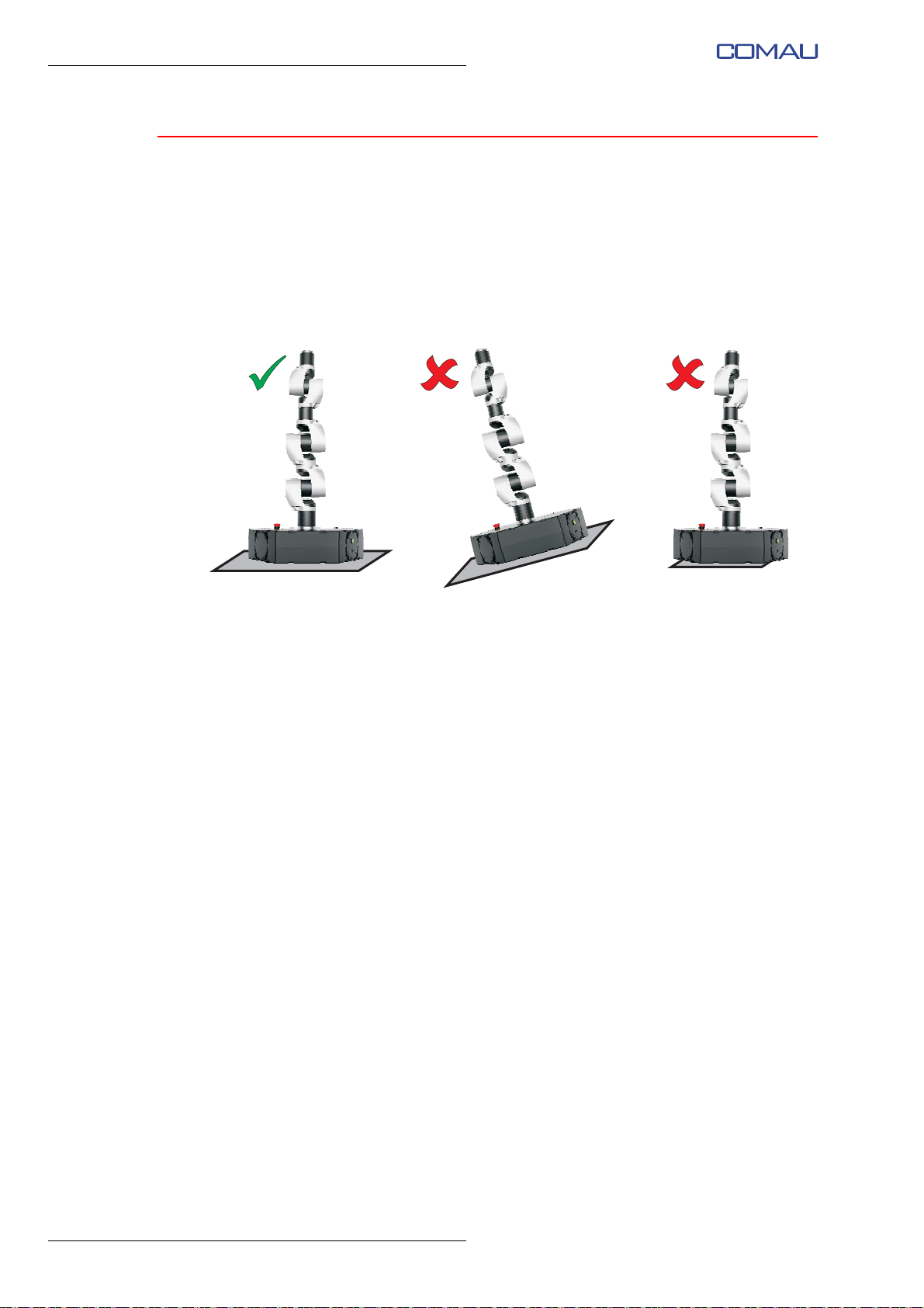
After removing the Robot from the packaging, position it on the supporting surface.
Make sure that the supporting surface:
– is not made of particularly slippery material;
– is not inclined (horizontal plane);
– has a larger supporting surface than the surface of the Robot base.
Check that under the Robot base there are not present objects (or similar) that can alter
the Robot stability during operation, with consequent risk of overturning.
20
Page 21
Comau Robotics Product Instruction
A
B
B1B
1
A1A
1
C
ROBOT HANDLING, ASSEMBLY AND FIRST START
3.4 Robot connection
In order to make the Robot operational it is necessary to make the following minimum
connections:
– Emergency stop push-button connection
– Connection to the electric power supply mains.
3.4.1 Emergency stop push-button connection
To connect the emergency push-button:
– connect the connector (A) to the connector (A1) present on Robot base;
– connect the cap connector (B1) to the connector (B) present on the emergency
push-button cable;
Failure to do this will impede the Robot to start.
– position the emergency push-button (C) in an easily accessible position outside the
Robot workspace.
Fig. 3.1 - Emergency stop push-button connection
21
Page 22
Comau Robotics Product Instruction
Electrical socket
90÷264 Vac
47÷63 Hz
A
B
C
ROBOT HANDLING, ASSEMBLY AND FIRST START
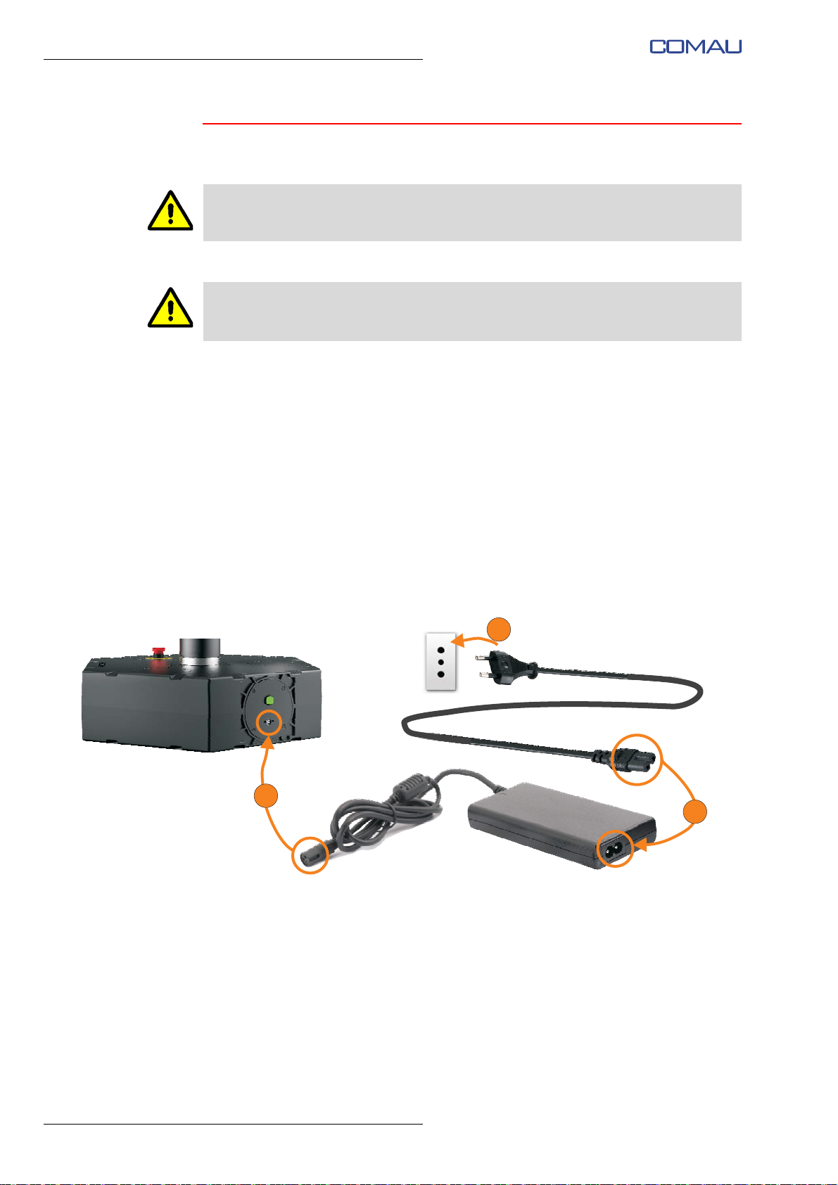
3.4.2 Connection to the electric power supply mains
Use only the power supply provided as standard with the Robot;
Check the integrity of the power cord and the power supply; in case the power cord is
damaged, do not connect it to the electrical mains and contact the Comau Service
Centre.
To connect the Robot to the power supply:
– Check that the power supply voltage and frequency of the electric network are
compatible with the electrical characteristics of the Robot (230 V, 50 Hz
respectively);
– make sure that the Robot is powered off (main switch open in 0 - OFF position);
– connect the power cord to the power supply (A);
– connect the power cord to the Robot base (B);
– connect the power cord to the power outlet (input voltage 90÷264 Vac, frequency
47÷63 Hz) (C).
Fig. 3.2 - Connection to electrical power mains
22
Representative figure illustrating the power supply with European 2-pole plug (Type C - CEE 7/16)
Page 23

ROBOT HANDLING, ASSEMBLY AND FIRST START
3.5 First power-up of the Robot
To power up the Robot for the first time:
– check that you have correctly performed the Connection to the electric power
supply mains and the Emergency stop push-button connection;
– check that no emergency push-button is pressed; if necessary, reset the
push-buttons by turning them in direction indicated by the arrows printed on the
push-buttons themselves;
– turn on the power supply by positioning the main switch on the Robot base in
closed position (1 - ON);
– check that on the joint management electronic boards (installed on the single
joints) the orange signalling LED blinks with a frequency of 1 time per second (1
Hz).
Comau Robotics Product Instruction
23
Page 24
Comau Robotics Product Instruction
CONFIGURATION AND CONNECTION OF THE COMMAND INTERFACE (TABLET)
4.
CONFIGURATION AND CONNECTION OF
THE COMMAND INTERFACE (TABLET)
– Requirements
– Download of the app
– Installation of the app
– Running of the app and connection to e.DO
– e.DO configuration
4.1 Requirements
The e.DO Robot can be controlled through a special app that can be installed on tablets
with Android operating system (supported versions: from Android 5.0 to 8.0.0) and with
a minimum screen size of 7”.
Below are the recommended requirements of the tablet, in order to allow a correct
running of the app:
– Wi-Fi connectivity - 802.11 a/b/g/n/ac
– CPU Octa-core (1.8 GHz Quad + 1.4 GHz Quad)
For an optimal app running, we recommend the use of Samsung Galaxy Tab S2 9.7”.
The fluidity and responsiveness of the app may depend on the technical features and
performance of the tablet (CPU, RAM, GPU, etc.).
24
Page 25
CONFIGURATION AND CONNECTION OF THE COMMAND INTERFACE (TABLET)
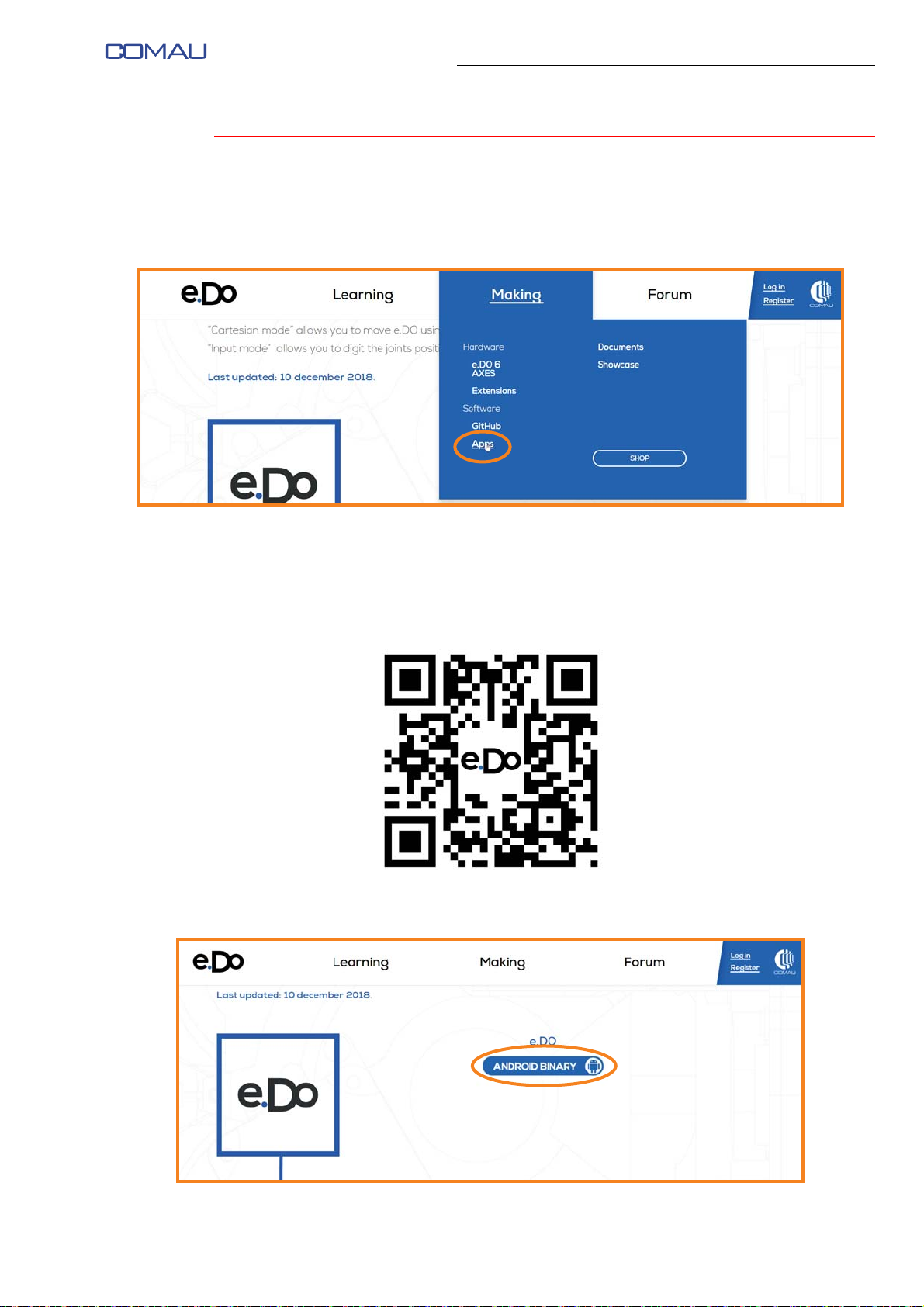
4.2 Download of the app
The app for e.DO control via tablet can be downloaded for free from the internet, directly
from the “Making / Apps” section of the website:
https://edo.cloud
Comau Robotics Product Instruction
The “Apps” section is accessible via:
– the link
https://edo.cloud/apps/
or
– by scanning the following QR code:
To download the app, click on the “Android Binary” button in the center of the web page
and save the “edo-ui-signed.apk” file.
25
Page 26
Comau Robotics Product Instruction
CONFIGURATION AND CONNECTION OF THE COMMAND INTERFACE (TABLET)
4.3 Installation of the app
Once the Download of the app is finished, open the file called “edo-ui-signed.apk” as
soon as it is downloaded.
Install the app by following the step-by-step wizard that will appear on the tablet screen.
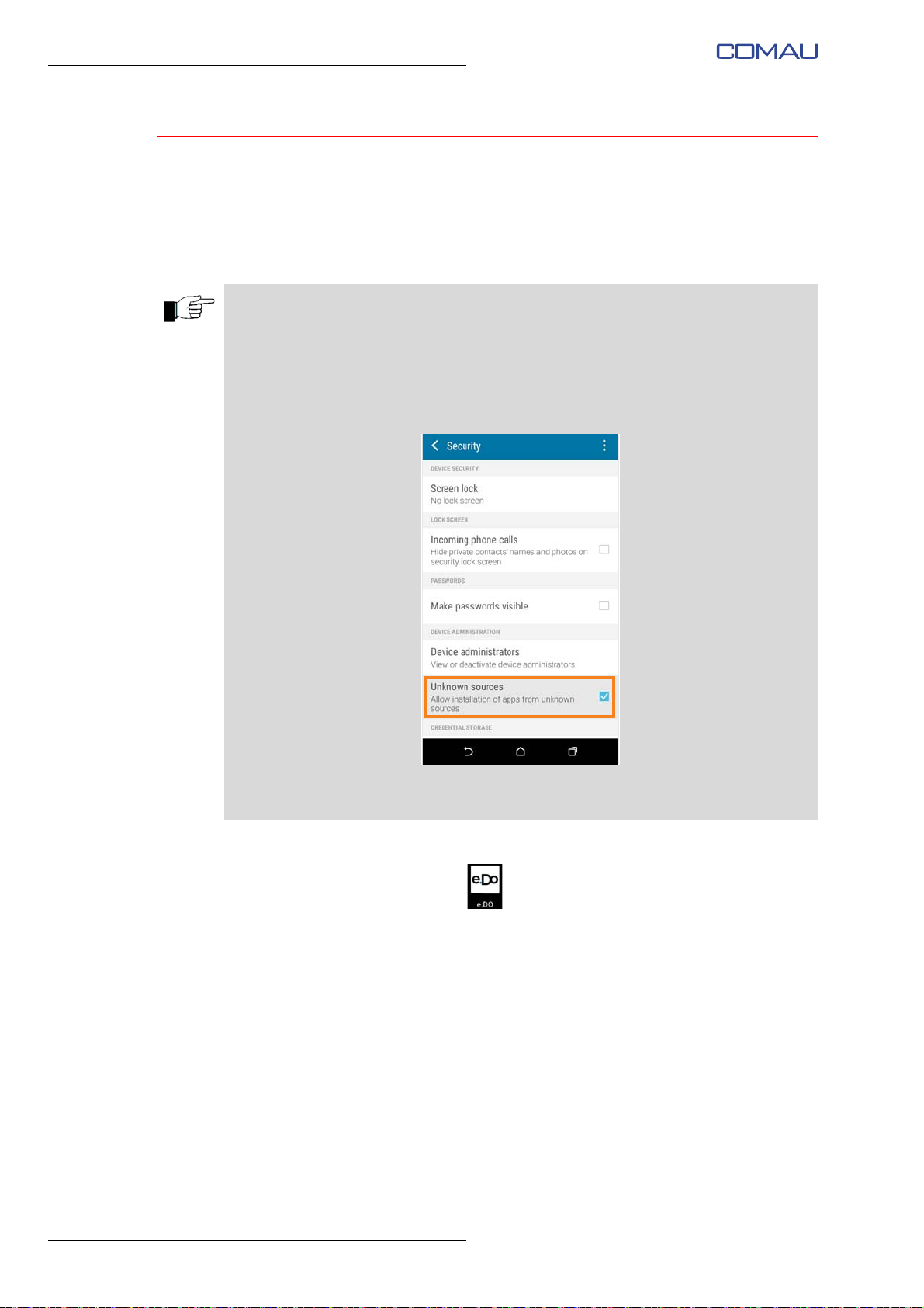
If, during the installation process, a warning message is displayed indicating that “For
security reasons, the tablet is not enabled to install unknown applications from this
source”*, proceed as follows:
– on the tablet, open the Settings menu -> Security;
– scroll until you find the item “Unknown sources”;
– enable the installation of apps from unknown sources, checking the related tick box
as shown in the following figure:
* the wording may vary depending on the tablet model and the version and/or customization of the tablet's
operating system.
At the end of the installation, the e.DO app will be available among the tablet
applications, identified by the icon
.
26
Page 27
Comau Robotics Product Instruction
CONFIGURATION AND CONNECTION OF THE COMMAND INTERFACE (TABLET)
4.4 Running of the app and connection to e.DO
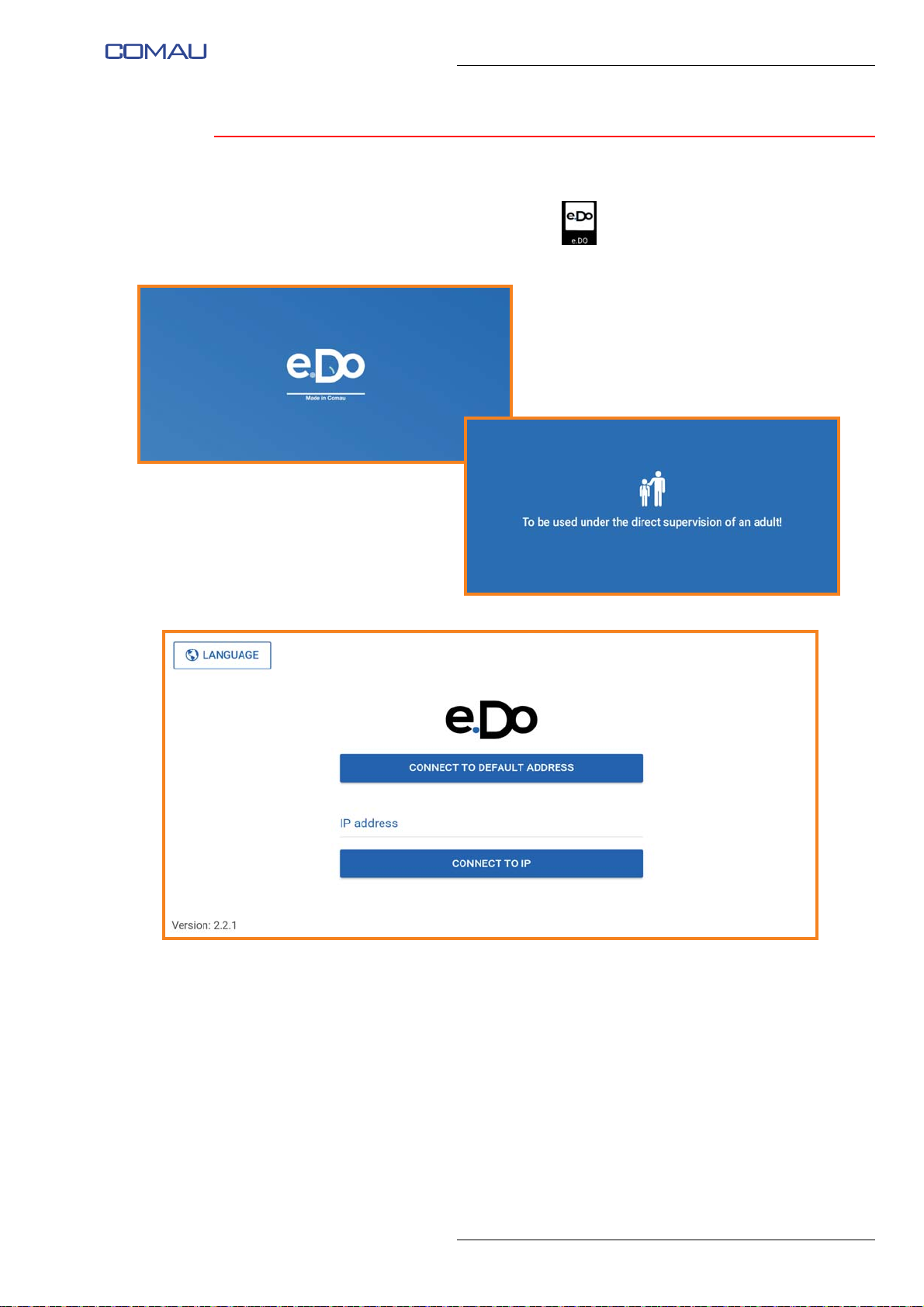
Open the e.DO app by tapping the icon .
When launched, the following screen images are displayed:
Once the app has been completely started, the following screen image appears:
Via this screen image it is possible to perform:
– Selection of interface language
– Connection to e.DO
as described below.
27
Page 28
Comau Robotics Product Instruction
CONFIGURATION AND CONNECTION OF THE COMMAND INTERFACE (TABLET)
4.4.1 Selection of interface language
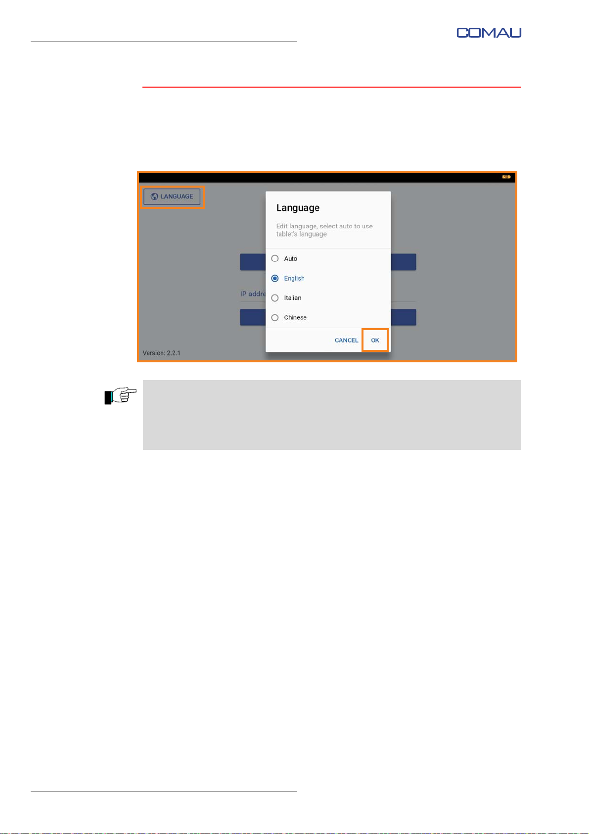
To select the language of the app interface:
– press the “Language” button at the top left of the app's main screen image;
– in the pop-up menu, select the desired language and confirm by pressing “OK”.
The application supports English, Italian and Traditional Chinese languages.
Selecting the “Auto” item, the application language will correspond to the system
language currently in use on the tablet.
In case the language currently used on the tablet is different from those supported by
the application, the English language will be set by default.
28
Page 29
CONFIGURATION AND CONNECTION OF THE COMMAND INTERFACE (TABLET)
xxx lb / xxx kg
REL. xxx
xxxx
xxxxxxxx
201x - xxxxxxx
C
4.4.2 Connection to e.DO
To connect the app to e.DO:
– connect e.DO to the power supply and switch it on, as indicated in the Robot
connection procedure described above;
– wait a few of minutes;
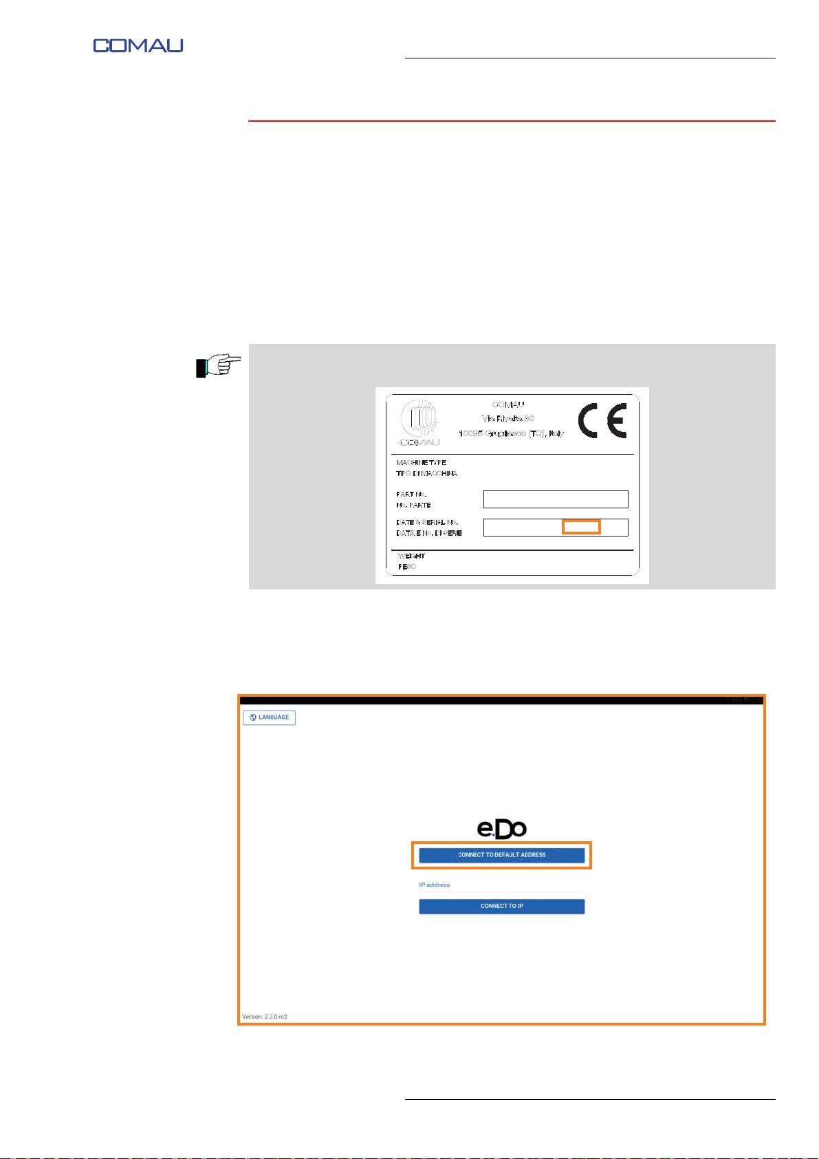
– open the tablet's network settings and access the “Wi-Fi” section; among the
available Wi-Fi networks, there will be a network named according to the following
syntax:
edo.wifi.SerialNumber*
*The e.DO Serial Number is indicated on the CE identification plate of the Robot, as
shown below:
Comau Robotics Product Instruction
– select the e.DO Wi-Fi network and make the connection; default password is
edoedoedo;
– open the e.DO app and, on the main page, click on “Connect to default address”
button.
29
Page 30
Comau Robotics Product Instruction
CONFIGURATION AND CONNECTION OF THE COMMAND INTERFACE (TABLET)
4.5 e.DO configuration
To start using e.DO, you need to configure it by performing the following steps:
– e.DO configuration selection
– e.DO calibration
4.5.1 e.DO configuration selection
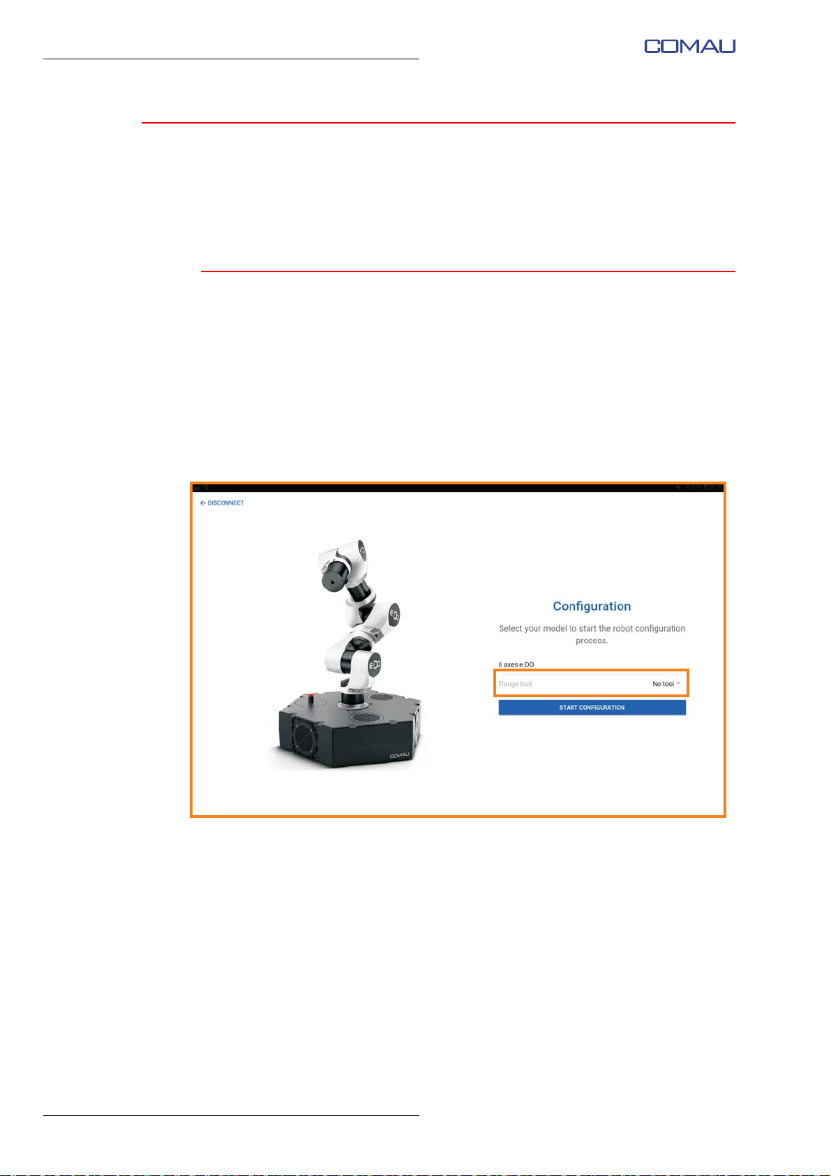
After connection of e.DO, the configuration selection page is displayed.
Through this page it is possible to select the configuration of e.DO tool, choosing one of
the available items from the drop-down menu:
- no tool
- e.DO Gripper
- Max Payload (to be used in the case where on the Robot wrist there is a tool having a
mass of 1 kg, corresponding to the maximum lifting capacity of the Robot “Payload”).
After selecting the configuration, confirm by pressing “Start configuration”; e.DO
calibration wizard will start automatically.
30
Page 31
CONFIGURATION AND CONNECTION OF THE COMMAND INTERFACE (TABLET)
4.5.2 e.DO calibration
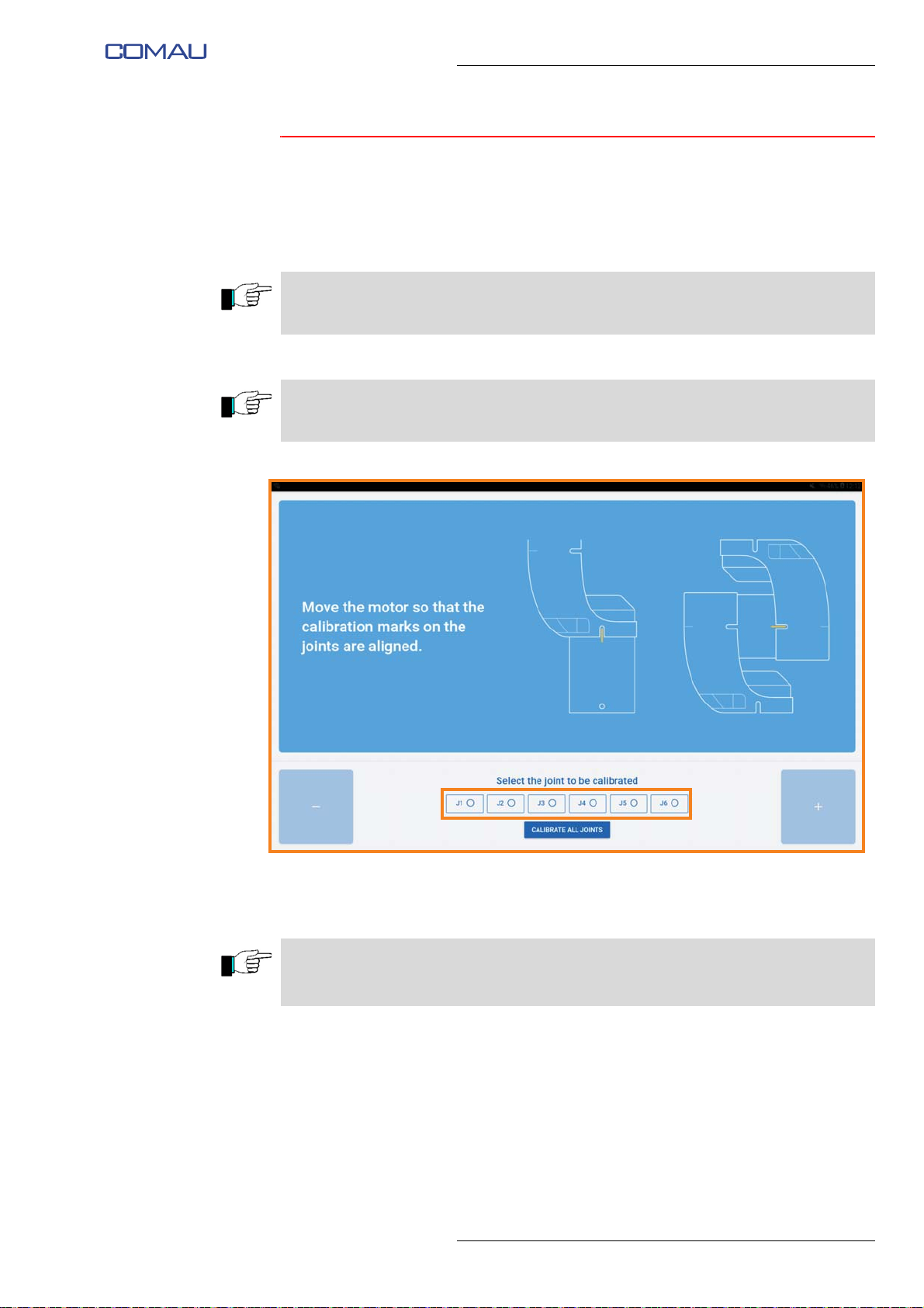
At the first start of e.DO, the calibration procedure is required.
To perform the calibration procedure, carry out the following steps:
– using the buttons at the bottom, select the joint to be calibrated;
The e.DO calibration must be performed on all joints; we recommend a progressive
calibration of the joints, from joint 1 to 6.
If the Robot is already in the calibration position (Robot in “vertical” position), it is
possible to calibrate all the joints simultaneously by pressing “Calibrate all joints” button.
Comau Robotics Product Instruction
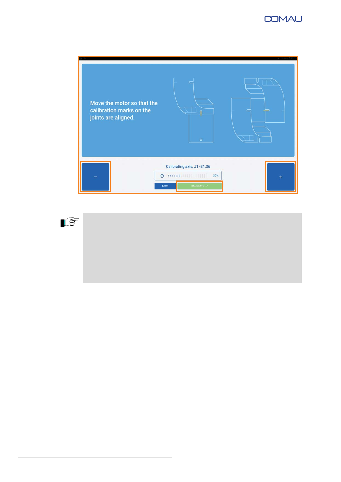
– using “+/-” buttons, move the selected joint as long as the calibration notches on
the Robot structure are aligned;
The axis “+/-” direction of rotation is indicated by special identification labels installed
directly on the Robot structure.
The axis movement speed can be adjusted through the slider in the center of the page.
31
Page 32
Comau Robotics Product Instruction
CONFIGURATION AND CONNECTION OF THE COMMAND INTERFACE (TABLET)
– once the correct alignment is obtained, confirm by pressing “Calibrate” button;
– repeat the calibration operations for the remaining axes of the Robot.
The e.DO calibration is required:
– after turning off e.DO, setting the main switch to the 0 - OFF position
– due to lack of electrical power supply to e.DO (for various reasons such as for
example lack of power supply directly from the electrical power mains,
disconnection of the power supply cord, etc.).
The e.DO calibration is not required:
– after pressing the emergency stop push-button
– after a collision
32
Page 33
Comau Robotics Product Instruction
USE OF THE “E.DO” APP
5.
USE OF THE “E.DO” APP
– How to move e.DO through the app
– How to create a movement program
– “Settings” Menu
– “About” Menu
5.1 How to move e.DO through the app
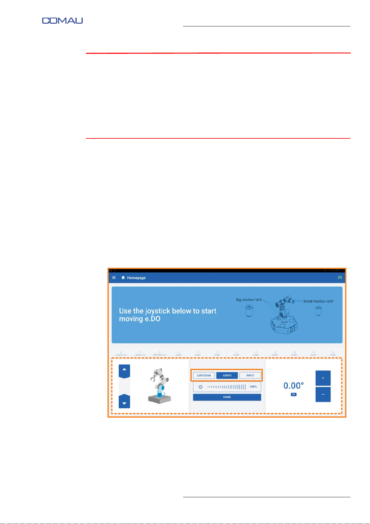
To move e.DO, it is necessary to access the Homepage of the app by selecting the
menu button at the top left, then selecting “Home” item.
The movement of e.DO through the app can be done in three different ways, described
below:
– Movement in Cartesian mode
– Movement in Joints mode
– Movement in Input mode
The movement mode can be selected by pressing one of the “Cartesian”, “Joints” or
“Input” buttons in the application homepage.
For each mode, specific information / commands will be displayed on the bottom of the
screen image (dotted area).
33
Page 34
Comau Robotics Product Instruction
X- Z+
Z-X+
Y-
Y+
USE OF THE “E.DO” APP
5.1.1 Movement in Cartesian mode
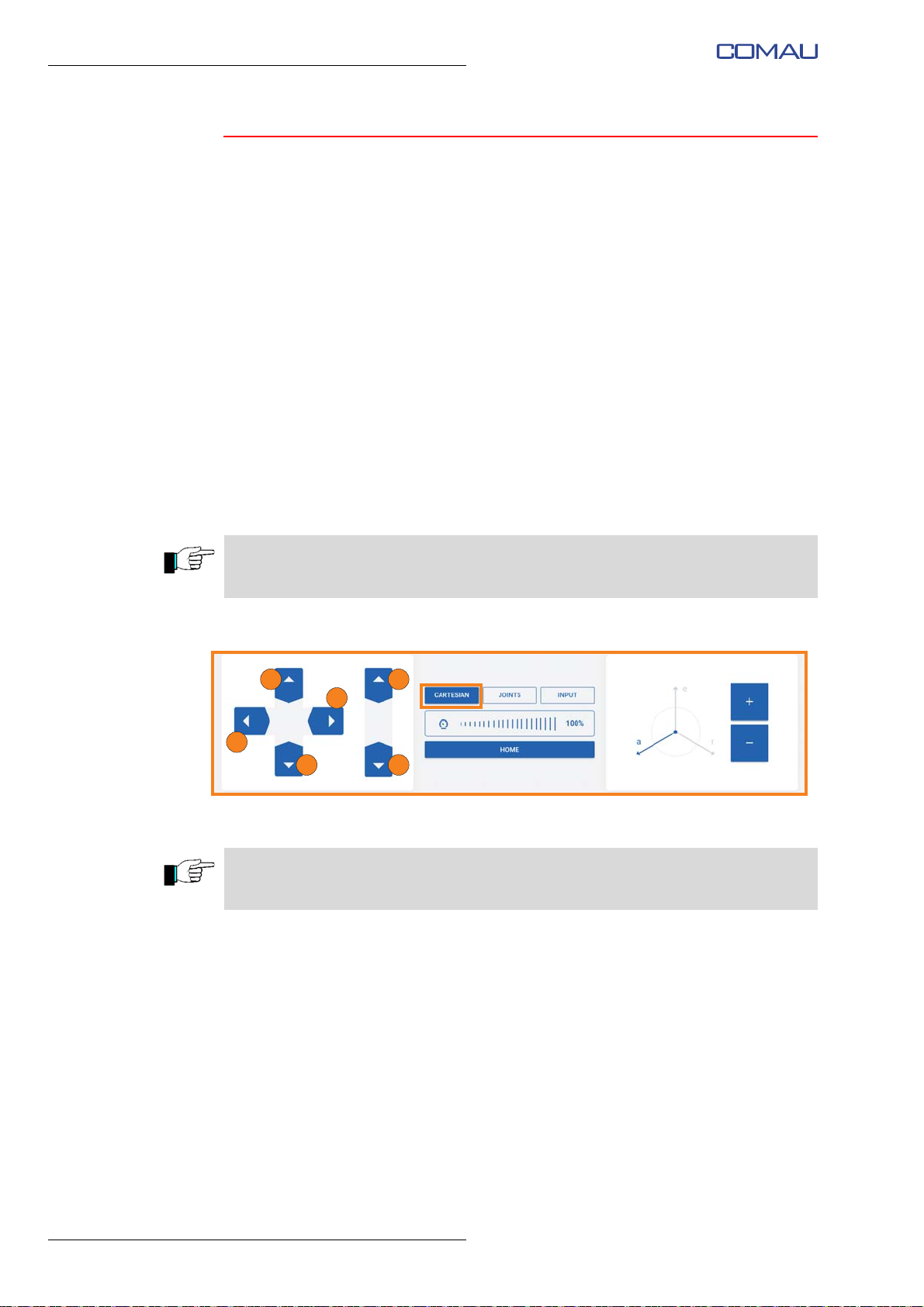
The movement in Cartesian mode allows e.DO to be moved using Cartesian
coordinates.
Movement modes
To carry out the movement in Cartesian mode:
– select the “Cartesian” item;
– if necessary, adjust the movement speed using the slider in the center of the
– using the directional arrows on the left side of the screen image, it is possible to
– furthermore, by manually selecting an axis (a, e, r) of the reference frame on the
screen image;
move the Robot in Cartesian mode, on the reference frame X, Y, Z (whose origin
is positioned on Robot base) as shown in the figure;
right side of the screen image (tap the axis to select it) it is possible to move the
Robot using the “+/-” keys; the Robot will move in Cartesian mode (coordinating all
the axes simultaneously) on the reference frame a, e, r.
The commands are of hold-to-run type; press and hold the directional arrows until the
Robot reaches the desired position.
The “Home” button allows you to move the Robot to the calibration position. The
command is of the hold-to-run type.
Stopping mode
In the Cartesian mode, the Robot stops automatically after releasing the directional
arrows on the left side of the screen image or after releasing the “Home” button.
34
Recovery mode from anomaly / collision
Following a collision, the Robot stops automatically and no movement is allowed
through the app; “Unbrake” screen image appears on the tablet (need for the execution
of the Robot axis brake release).
To perform the recovery after the collision it is necessary to perform the Robot axis
break release through the relevant screen image on the tablet. After the collision it is not
necessary to calibrate the Robot.
Page 35
5.1.2 Movement in Joints mode
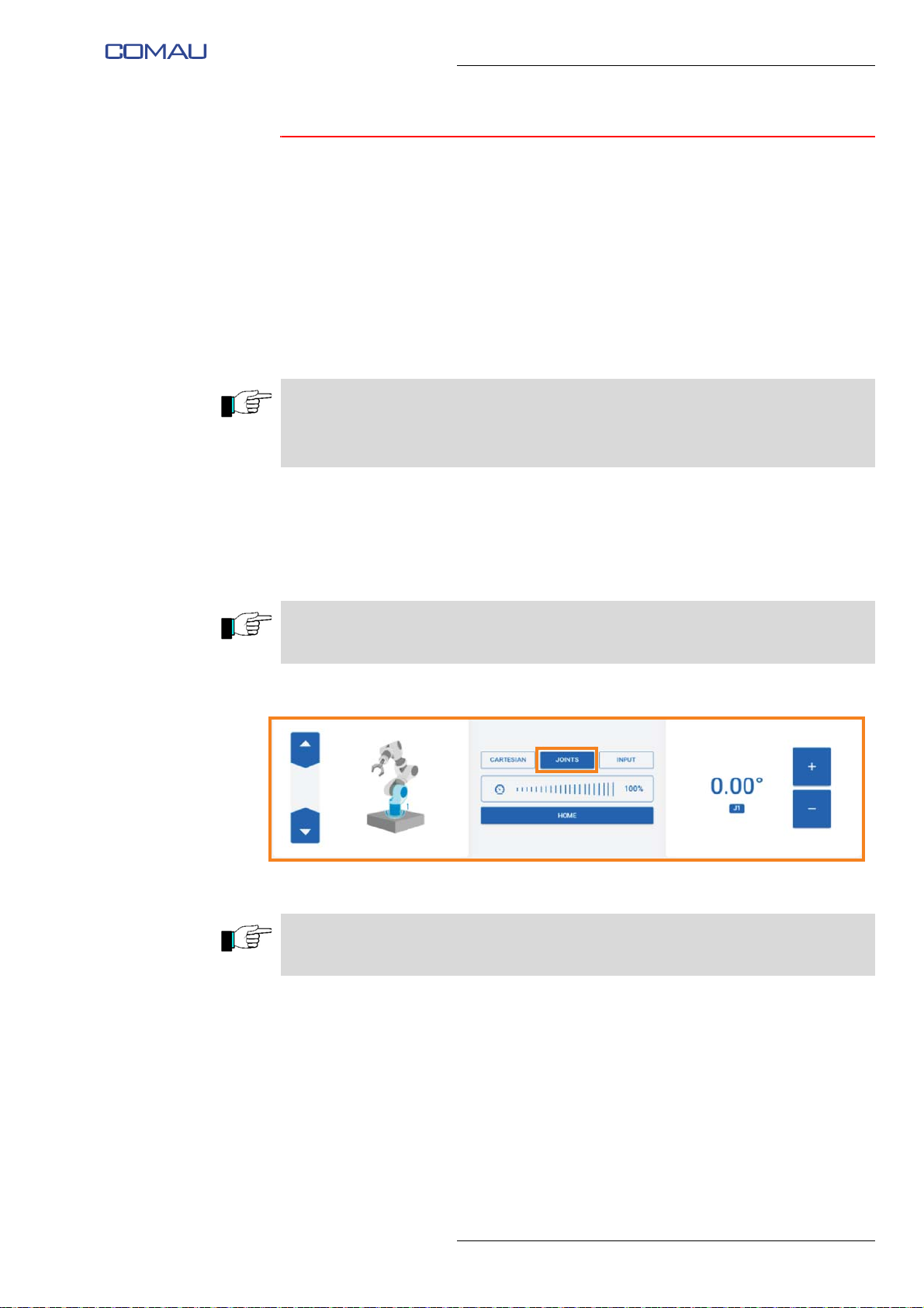
The movement in Joints mode makes it possible to move the e.DO axes (joints) one at
a time by selecting them individually directly from the app interface.
Movement modes
To carry out the movement in Joints mode:
– select the “Joints” item;
– using the arrows on the left side of the page, select the joint you want to move; the
selected joint will be highlighted on the image illustrating the Robot;
When present, the e.DO Gripper is identified as an additional joint (joint 7) and can be
moved in the same modes as the other joints of the Robot. By pressing the “+” key, it
commands the opening of e.DO Gripper; by pressing the “-” key, it commands the e.DO
Gripper to close.
Comau Robotics Product Instruction
USE OF THE “E.DO” APP
– if necessary, adjust the movement speed using the slider in the center of the
screen image;
– move the selected joint using the “+/-” arrow keys on the right side of the screen
image.
The commands are of hold-to-run type; press and hold the “+” or “-” key until the selected
joint reaches the desired position.
The “Home” button allows you to move the Robot to the calibration position. The
command is of the hold-to-run type.
Stopping mode
In the Joints mode, the Robot stops automatically after pressing and holding the “+/-”
keys on the right side of the screen image or after releasing the “Home” button.
35
Page 36

Comau Robotics Product Instruction
USE OF THE “E.DO” APP
Recovery mode from anomaly / collision
Following a collision, the Robot stops automatically and no movement is allowed
through the app; “Unbrake” screen image appears on the tablet (need for the execution
of the Robot axis brake release).
To perform the recovery after the collision it is necessary to perform the Robot axis
break release through the relevant screen image on the tablet. After the collision it is not
necessary to calibrate the Robot.
36
Page 37
5.1.3 Movement in Input mode
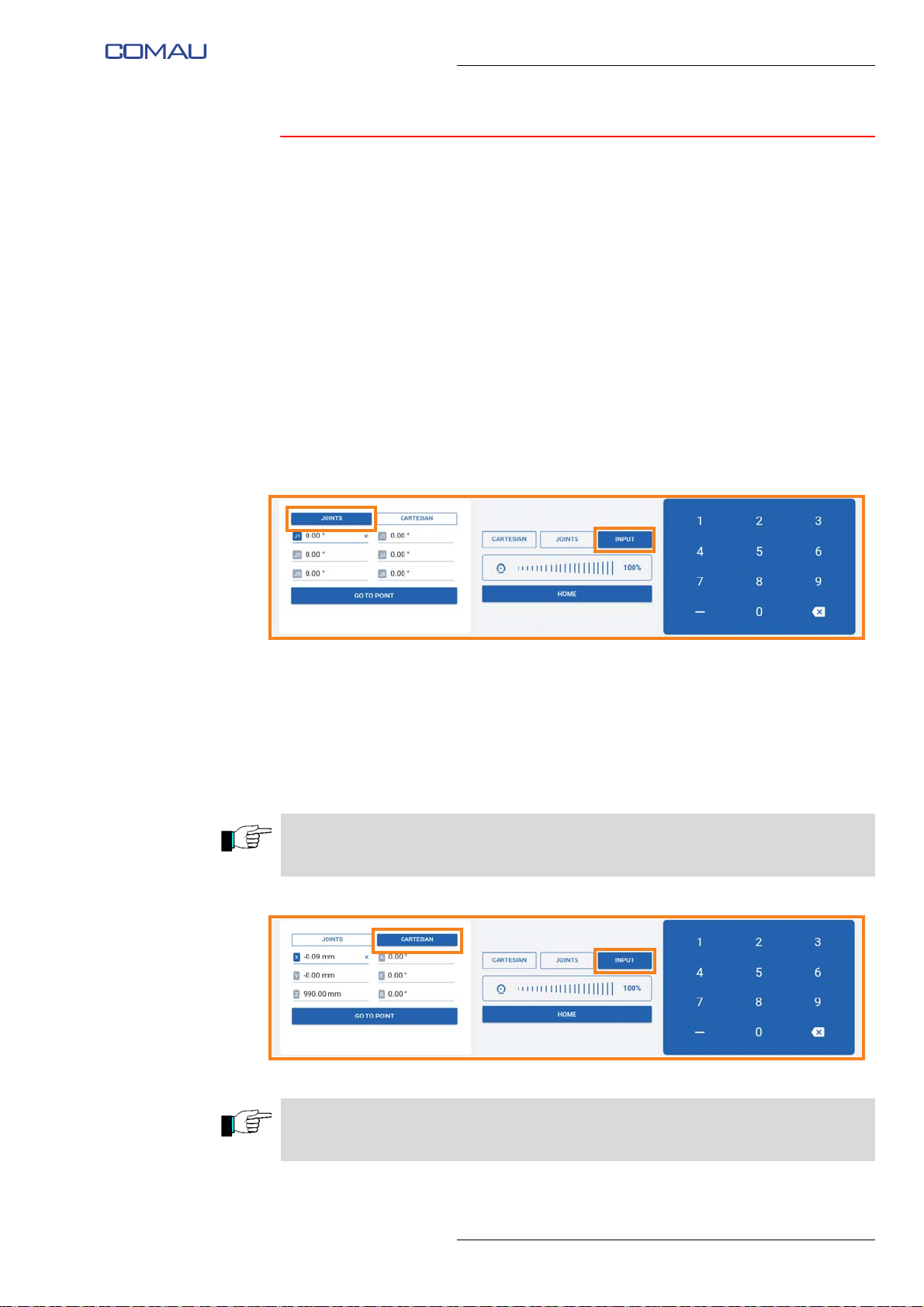
The movement in Input mode makes it possible to manually enter the coordinates of the
individual points you want e.DO to reach; e.DO will reach the set points by automatically
coordinating the movements of the individual axes.
Movement modes
To carry out the movement in Input mode:
– select the “Input” item present in the center of the screen image;
– on the left side of the screen image, select the mode (Joints or Cartesian) through
which to enter the coordinates of the point that you want to be reached by e.DO;
– in case of selection of “Joints”
• select the various joints individually (J1 ÷ J6);
• using the numeric keypad on the right, enter the value in degrees for each
joint movement;
• then, press “Go to point” button to move the Robot to the desired point.
Comau Robotics Product Instruction
USE OF THE “E.DO” APP
– in case of selection of “Cartesian”
• using the numeric keypad on the right, enter the desired coordinates for each
axis (reference frame X, Y, Z with the origin in the center of the joint 1 on
Robot base);
• using the numeric keypad on the right, enter the desired degrees for each
corner (a, e, r);
• then, press the “Go to point” button to move the Robot to the desired point.
The “Go to point” button is of the hold-to-run type; press and hold the button until the
Robot reaches the desired position.
The “Home” button allows you to move the Robot to the calibration position. The
command is of the hold-to-run type.
37
Page 38

Comau Robotics Product Instruction
USE OF THE “E.DO” APP
Stopping mode
In the Input mode, the Robot stops automatically after releasing the “Go to point” button
or after releasing the “Home” button.
Recovery mode from anomaly / collision
Following a collision, the Robot stops automatically and no movement is allowed
through the app; “Unbrake” screen image appears on the tablet (need for the execution
of the Robot axis brake release).
To perform the recovery after the collision it is necessary to perform the Robot axis
break release through the relevant screen image on the tablet. After the collision it is not
necessary to calibrate the Robot.
38
Page 39
Comau Robotics Product Instruction
USE OF THE “E.DO” APP
5.2 How to create a movement program
e.DO allows the user to create small movement programs, to be run in automatic mode.
The creation of a movement program is possible in the following 2 ways:
– Creating a movement program through “Projects” page;
– Creating a movement program through “Blockly”.
5.2.1 Creating a movement program through “Projects” page
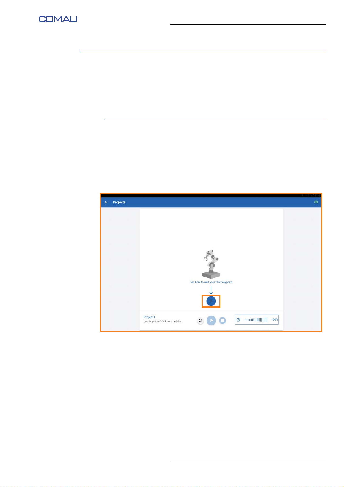
To create a movement program you need to:
– access the “Projects” page using the drop-down menu in the left area of the “Home
page”;
– create a new project, entering the desired name by means of the relevant pop-up
window that will appear at the time of the project creation;
– press “+” button to create a new point
39
Page 40
Comau Robotics Product Instruction
A
C D E
FB
USE OF THE “E.DO” APP
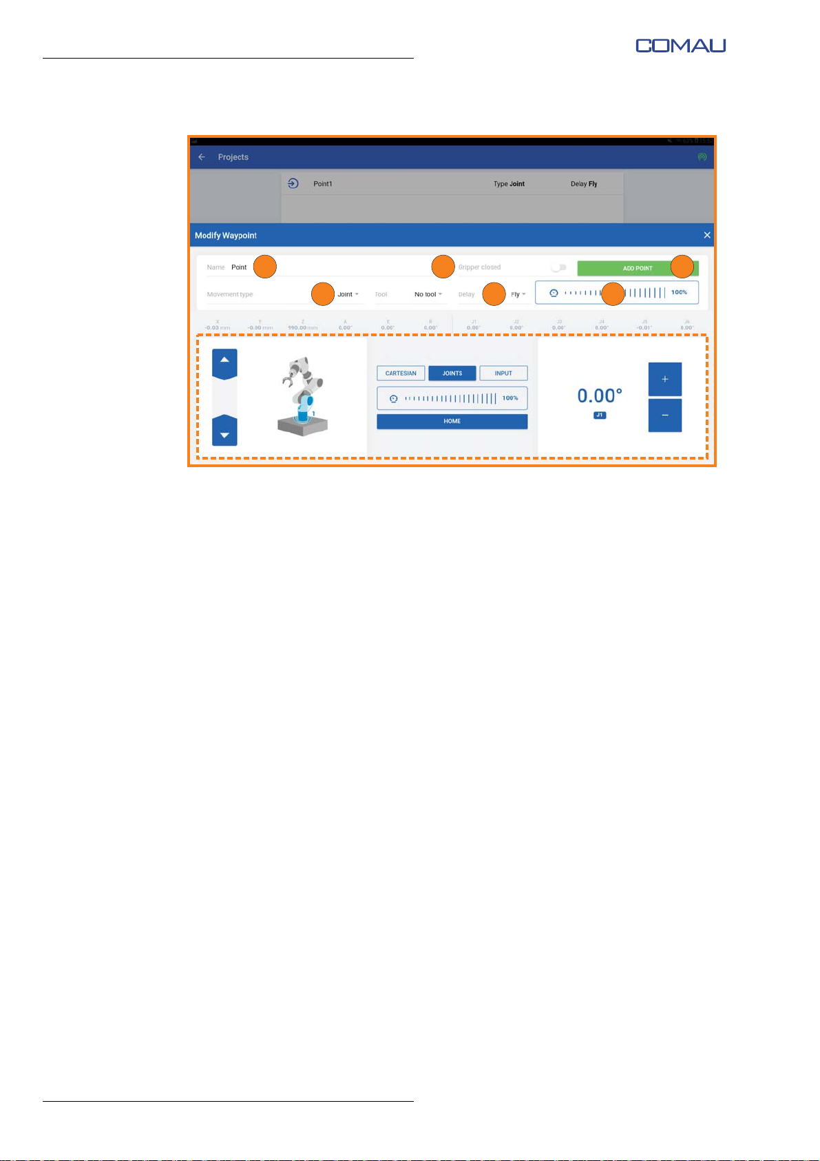
– a new point creation screen image will open;
– assign a name to the point (“Name” field (A) at the top left);
– if present, select the open or closed position of the e.DO Gripper (“Gripper closed”
switch (B) at the top right);
– select the type of movement with which you want to save the point, to be chosen
between Joints and Cartesian (“Movement type” field (C) at the top left);
– set the delay time, which elapses from the reaching of the previous point to the
beginning of the Robot movement towards the next point (“Delay” field (D) at the
top right). It is possible to set a zero delay by selecting “Fly”, or a delay in seconds
that can be selected from the drop-down menu;
– set the speed with which the Robot will move to the desired point during program
execution (“Speed” slider (E) at the top right);
– manually move the Robot to the desired point using the commands present in the
lower part of the screen image (dotted area), according to one of the previously
described movement modes (
mode or Movement in Input mode);
– having obtained the correct positioning of the Robot, confirm the creation of the
point by pressing the green button “Add point” (F) at the top right;
– following the same procedure, create the remaining points of the movement
program;
Movement in Cartesian mode, Movement in Joints
40
Page 41
Comau Robotics Product Instruction
G
Edit
Delete
Sort
Clone
Delete
Sort
Clone
K HJ
USE OF THE “E.DO” APP
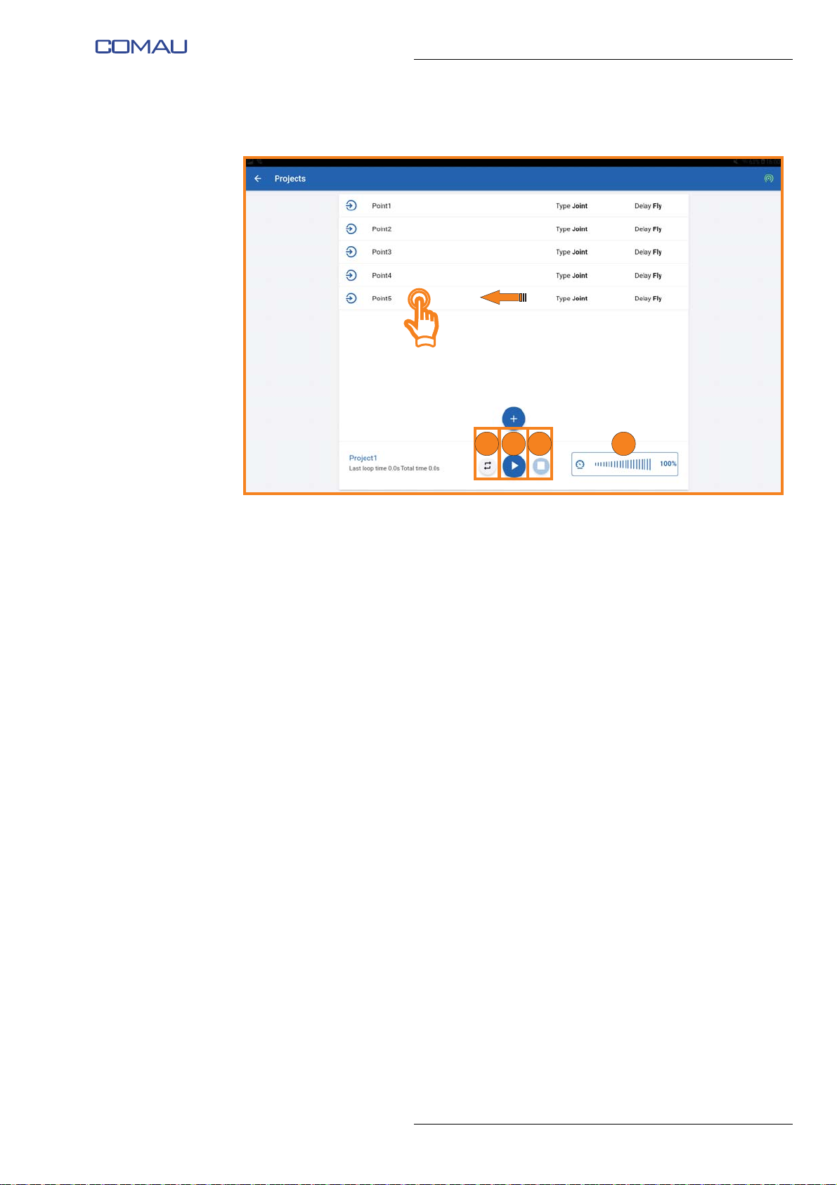
– at the end of program creation, a screen image similar to the following will be
displayed;
– you can:
• modify a previously created point by tapping on the corresponding line;
• delete, sort or clone a point by swiping from right to left on the corresponding
line;
– set the number of times in which the Robot will cyclically repeat the movement
program just created by pressing the “Repeat” button (G);
– using the slider (H), set the speed at which the Robot will execute the movement
program;
– execute the movement program by pressing the “Play” button (H);
– the movement program can be stopped by pressing the “Stop” button (J).
41
Page 42
Comau Robotics Product Instruction
USE OF THE “E.DO” APP
5.2.2 Creating a movement program through “Blockly”
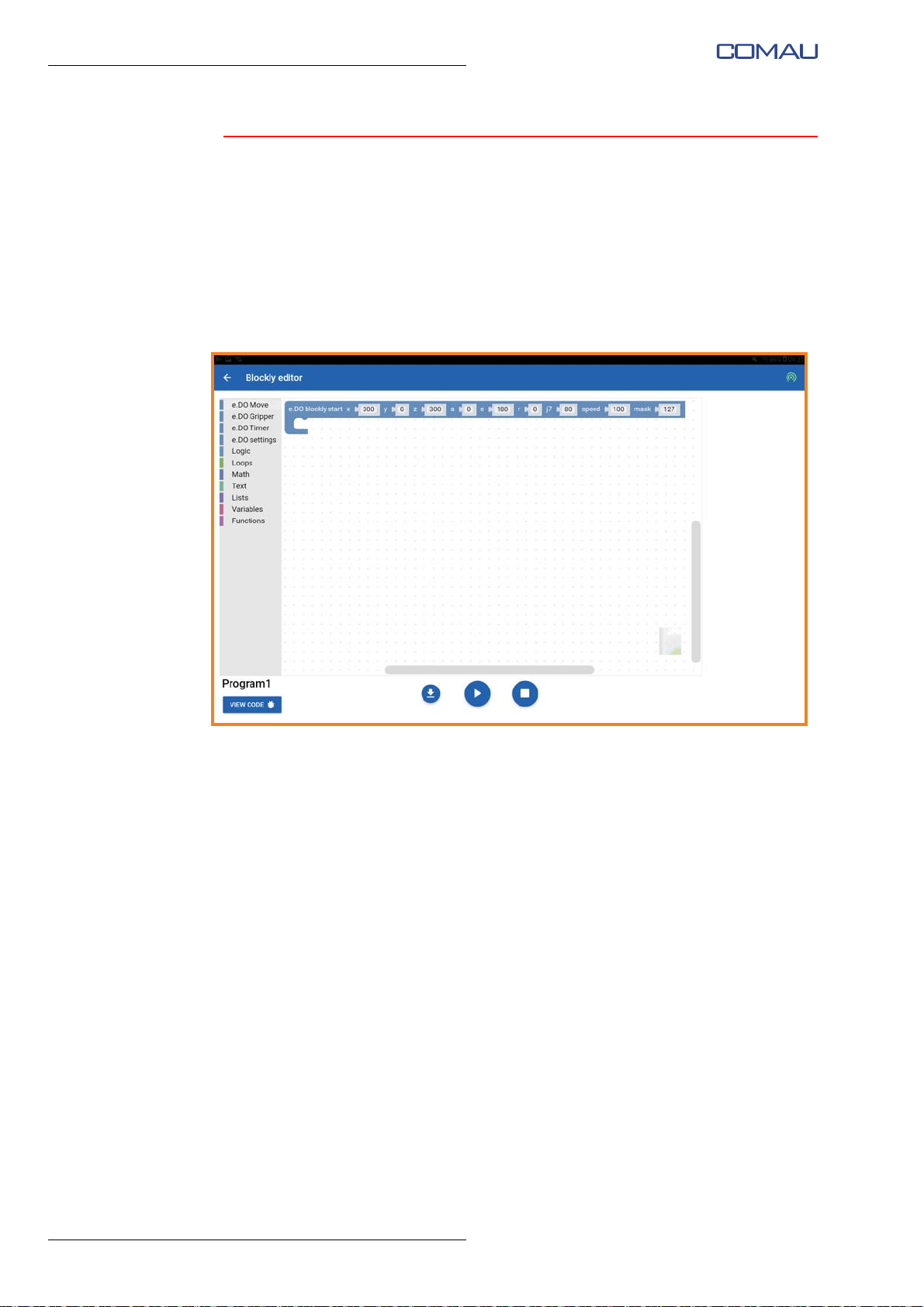
To create a movement program through Blockly, you need to:
– access the “Blockly” page using the drop-down menu in the left area of the “Home
– press the “+” button to create a new project, entering the desired name by means
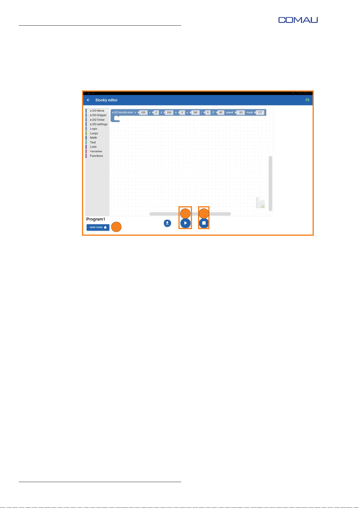
– “Blockly editor” screen image for creating the new Blockly program will open; the
page”;
of the related pop-up window that will appear at the time of the project creation;
first block “e.DO Blockly start” will be created automatically;
42
Page 43
Comau Robotics Product Instruction
USE OF THE “E.DO” APP
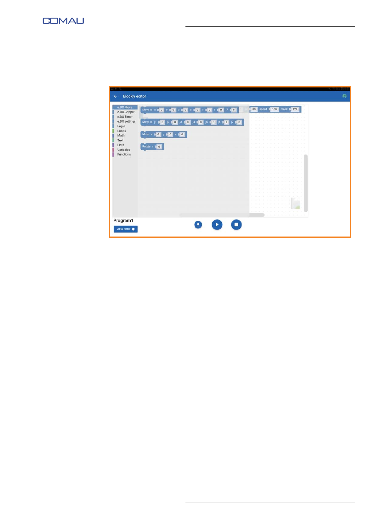
– from the menu on the left side you can select a series of operating blocks:
• specific for e.DO (the first 4 from the top, described below), or
• belonging to the standard Blockly libraries (the methods of use of which can
be found at the following address https://developers.google.com/blockly/);
– e.DO specific blocks have the following functionality / characteristics:
• “e.DO Move” blocks allow to enter e.DO movement commands in Joints or
Cartesian mode;
• “e.DO Gripper” blocks allow to enter e.DO Gripper movement commands
(opening / closing) and to measure the opening level of the e.DO Gripper
itself;
• “e.DO Timer” blocks allow to enter delays between the movements;
• “e.DO Settings” blocks allow to enter the settings of individual e.DO
movements (e.g. speed of the movements);
– by dragging the various blocks into the “Blockly editor” programming space, you
can create Robot movement programs;
– within each block it is possible to enter specific parameters, tapping on the desired
field and entering the relevant value;
43
Page 44
Comau Robotics Product Instruction
C
BA
USE OF THE “E.DO” APP
– once the program has been completed it is possible to:
• start / stop using “Play” (A) and “Stop” (B) buttons present at the bottom of the
screen image;
• display the source code of the program by pressing “View code” button (C) in
the lower left corner of the screen image.
44
Page 45
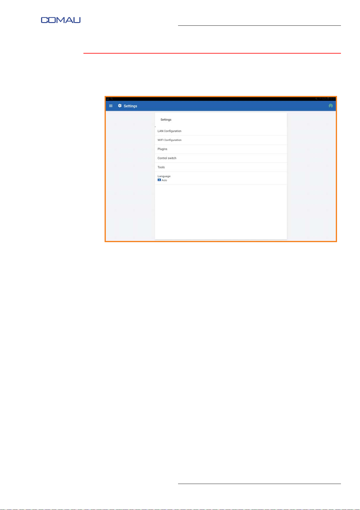
5.3 “Settings” Menu
“Settings” menu is accessible by selecting the menu button at the top left, then selecting
the “Settings” item.
Comau Robotics Product Instruction
USE OF THE “E.DO” APP
Through the “Settings” menu, you can access a series of Robot settings pages:
– LAN Configuration
– Wi-Fi Configuration
– Blockly
– Control switch
– Language
45
Page 46
Comau Robotics Product Instruction
USE OF THE “E.DO” APP
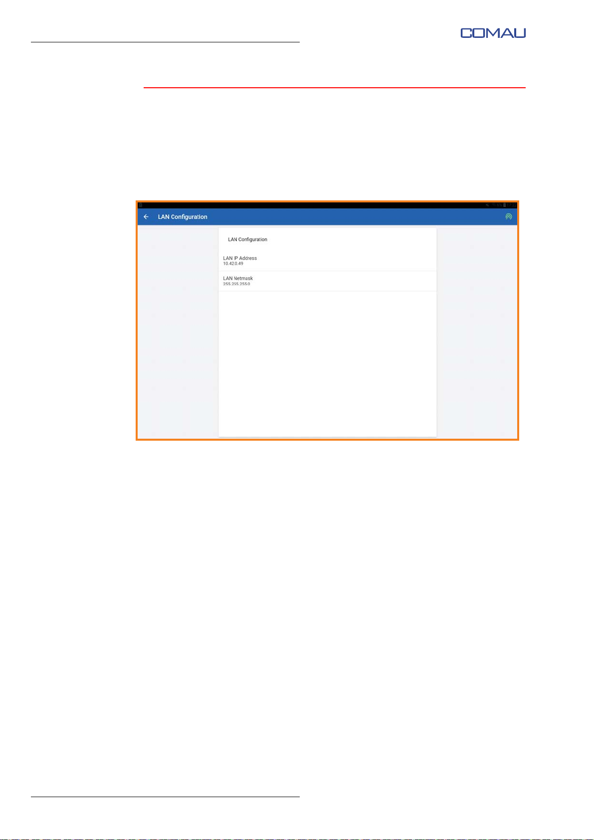
5.3.1 LAN Configuration
Through “LAN Configuration” page, it is possible to access the page showing the
information relating to the LAN to which the Robot is connected, and to modify the
related properties/settings:
– LAN IP Address: Robot IP address
– LAN Netmask: Subnet mask
46
Page 47
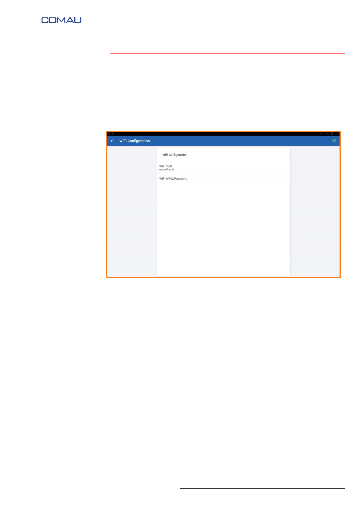
5.3.2 Wi-Fi Configuration
Through “Wi-Fi Configuration” page, it is possible to access the page showing the
information relating to the Wi-Fi network to which the Robot is connected, and to modify
the related properties/settings:
– WiFi SSID: identification name of the Wi-Fi network
– WiFi WPA2 Password: indicates the security protocol used to protect the Wi-Fi
network.
Comau Robotics Product Instruction
USE OF THE “E.DO” APP
47
Page 48
Comau Robotics Product Instruction
USE OF THE “E.DO” APP
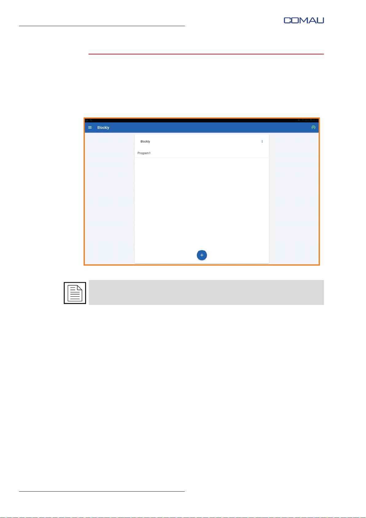
5.3.3 Blockly
Through the “Blockly” page, it is possible to create e.DO movement programs using a
simplified visual programming environment composed of function blocks, each
corresponding to a specific command.
To create a program, simply drag the desired blocks into the appropriate programming
spa
ce, positioning and constraining them in order to obtain the desired function.
For more information on creating programs with Blockly, see par. 5.2 How to create a
movement program on pag. 5-39.
48
Page 49
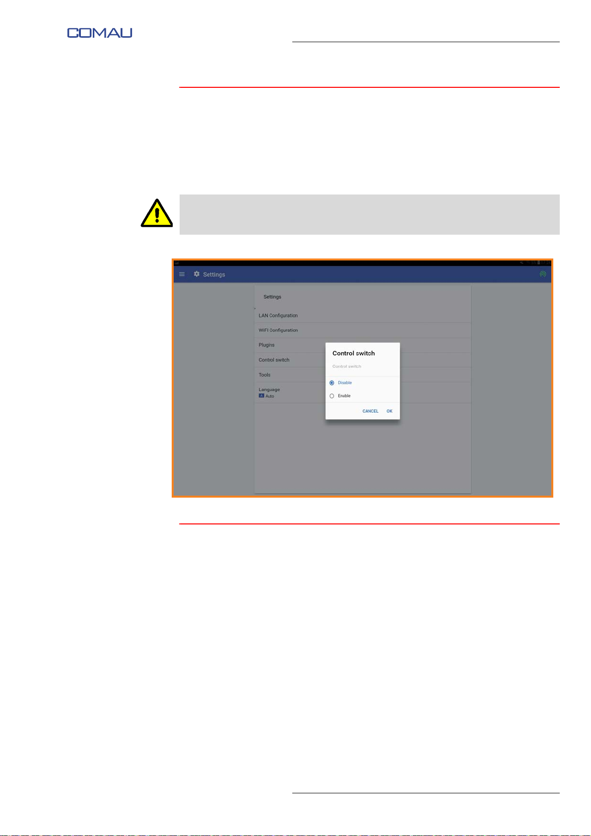
5.3.4 Control switch
Selecting the “Control switch” item, a pop-up window will appear through which it will be
possible to switch the e.DO control mode from tablet to Teach Pendant after a specific
Procedure for connecting e.DO to the Desk Simulator and related configuration, as
described in the Service Manual.
By enabling the functionality, e.DO can be controlled through the Teach Pendant.
The movement of the Robot through the Teach Pendant is allowed only to personnel
adequately instructed and trained to use the Teach Pendant itself.
Comau Robotics Product Instruction
USE OF THE “E.DO” APP
5.3.5 Language
Selecting the “Language” item, a pop-up window will be displayed through which you
can set the language of the app, according to the methods indicated in the par. 4.4.1
Selection of interface language on pag. 4-28.
49
Page 50
Comau Robotics Product Instruction
USE OF THE “E.DO” APP
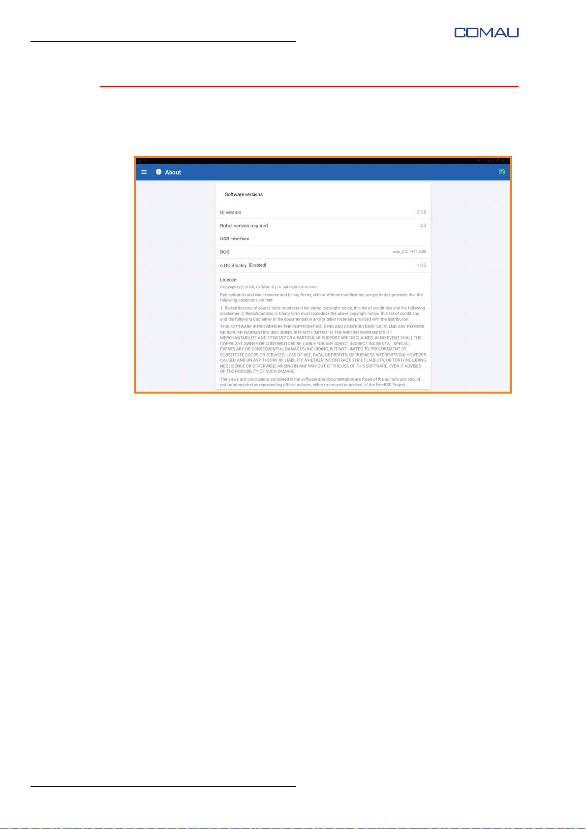
5.4 “About” Menu
“About” menu is accessible by selecting the menu button at the top left, then selecting
the “About” item.
Through this page you can view information relating to the firmware version of various
HW and SW elements of e.DO.
50
Page 51

Comau Robotics Product Instruction
AVAILABLE OPTIONS FOR E.DO
6.
AVAILABLE OPTIONS FOR E.DO
e.DO can be equipped with the following optional devices, in order to expand its
functionalities:
– e.DO Gripper
– e.DO Marker Holder
The use of other tools or extensions different from those indicated in this chapter is to
be understood as “incorrect use” of the Robot and therefore involves the forfeiture of the
CE certification of the Robot.
Any damage to the Robot generated by or during the use of other tools or extensions
other than those indicated in this chapter are not covered by the warranty.
51
Page 52
Comau Robotics Product Instruction
AVAILABLE OPTIONS FOR E.DO
6.1 e.DO Gripper
– What is the e.DO Gripper for?
– e.DO Gripper technical features
– Safety requirements for e.DO Gripper use
– e.DO Gripper diagrams and drawings
– How to mount the e.DO Gripper on the e.DO Robot
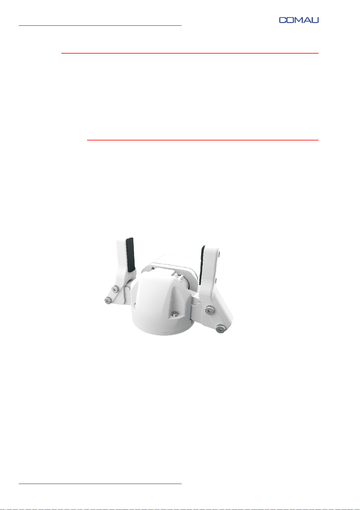
6.1.1 What is the e.DO Gripper for?
The e.DO Gripper is a gripper specifically designed to be installed on the wrist of the
e.DO Robot.
The e.DO Gripper allows the execution of programs including small operations for
handling small and non-dangerous objects, compatibly with
of the e.DO Robot and e.DO Gripper technical features.
General technical features
Fig. 6.1 - e.DO Gripper - Overview
52
Page 53
6.1.2 e.DO Gripper technical features
Tab. 6.1 - e.DO Gripper technical features
Description Feature
Type 2-finger (fingertips) Gripper
Weight 200 g
Stroke With neoprene fingertip cover 77 mm
Payload 400 g
Opening / closing maximum speed 80 mm/s
Clamping force <65 N
On-board sensors / Position
identification system
Comau Part No. CR82442100
Comau Robotics Product Instruction
AVAILABLE OPTIONS FOR E.DO
Encoder
For information on the maximum load supported by the Robot, refer to par. Robot wrist
features in the Service Manual.
6.1.3 Safety requirements for e.DO Gripper use
– During motion, do not insert body parts (fingers, hands, arms, etc.) between the
gripper fingers of the e.DO Gripper in order to avoid possible pinching;
– handle exclusively objects of conformation such as to guarantee a good grip on the
part of e.DO Gripper;
When using the e.DO Gripper, wear safety glasses of F.F. class (low energy impact).
Do not use the e.DO Gripper working with wet or damp hands or feet.
In the event of a fault or malfunction, do not disassemble or attempt to repair the e.DO
Gripper by yourself; contact the Comau Service Center. See also the following address:
edo.cloud/support-and-contacts/.
6.1.4 e.DO Gripper diagrams and drawings
For detailed instructions, connection diagrams, and drawings of the e.DO Gripper,
consult the Service Manual.
53
Page 54

Comau Robotics Product Instruction
AVAILABLE OPTIONS FOR E.DO
6.1.5 How to mount the e.DO Gripper on the e.DO Robot
For detailed instructions and mounting procedures of the e.DO Gripper on the e.DO
Robot, consult the Service Manual.
54
Page 55
6.2 e.DO Marker Holder
– What is the e.DO Marker Holder for?
– Safety requirements for e.DO Marker Holder use
– e.DO Marker Holder diagrams and drawings
– How to mount the e.DO Marker Holder on the e.DO Robot
– How to fix the marker on the e.DO Marker Holder
6.2.1 What is the e.DO Marker Holder for?
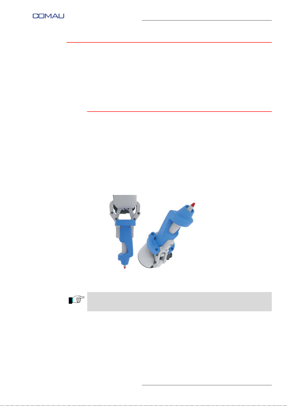
The e.DO Marker Holder is a tool specifically designed to be installed on the wrist of the
e.DO Robot.
The e.DO Marker Holder allows you to fix on the wrist of the e.DO Robot a felt-tip marker
and have e.DO write operations on flat surfaces.
The surfaces on which it is possible to write with the e.DO Marker Holder must be
horizontal and parallel to the floor.
Comau Robotics Product Instruction
AVAILABLE OPTIONS FOR E.DO
Fig. 6.2 - e.DO Marker Holder - Overview
The e.DO Marker Holder can be mounted directly on the Robot flange, or used matching
it with the e.DO Gripper.
55
Page 56
Comau Robotics Product Instruction
AVAILABLE OPTIONS FOR E.DO
6.2.2 Safety requirements for e.DO Marker Holder use
When using the e.DO Marker Holder, wear safety glasses of F.F. class (low energy
impact).
6.2.3 e.DO Marker Holder diagrams and drawings
For detailed instructions and drawings of the e.DO Marker Holder, consult the Service
Manual.
6.2.4 How to mount the e.DO Marker Holder on the e.DO Robot
For detailed instructions and mounting procedures of the e.DO Marker Holder on the
e.DO Robot, consult the Service Manual.
56
Page 57
Comau Robotics Product Instruction
A B
AVAILABLE OPTIONS FOR E.DO
6.2.5 How to fix the marker on the e.DO Marker Holder
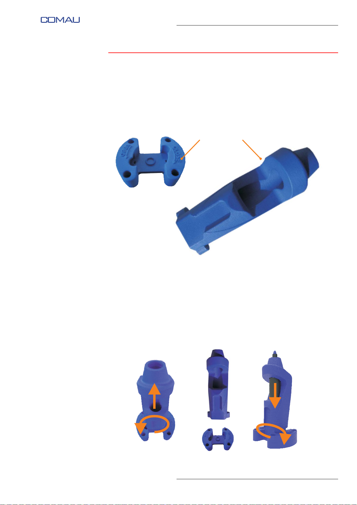
The e.DO Marker Holder consists of 2 main parts:
– a base flange (A) (to be fixed to the Robot)
– a marker holder (B) (to be fixed on the base flange)
Fig. 6.3 - e.DO Marker Holder - Composition
To fix the marker on the e.DO Marker Holder you need to:
– remove the marker holder (B) from the base flange (A), turning it counterclockwise,
as indicated by the arrow “OPEN” stamped on the flange itself;
– insert the felt-tip marker into the marker holder (B);
– reposition the marker holder (B) on the base flange (A) matching the “teeth” on the
marker holder with the corresponding notches on the flange;
– fix the marker holder (B) to the base flange (A), turning it clockwise, as indicated
by the arrow “CLOSE” stamped on the flange itself.
57
Page 58
Comau Robotics Product Instruction
E.DO CLEANING INSTRUCTIONS AND PERIODIC CHECKS
7.
E.DO CLEANING INSTRUCTIONS AND
PERIODIC CHECKS
To keep e.DO efficient and properly functioning it is necessary to periodically carry out
cleaning operations and checks as described and summarized below in the following
table.
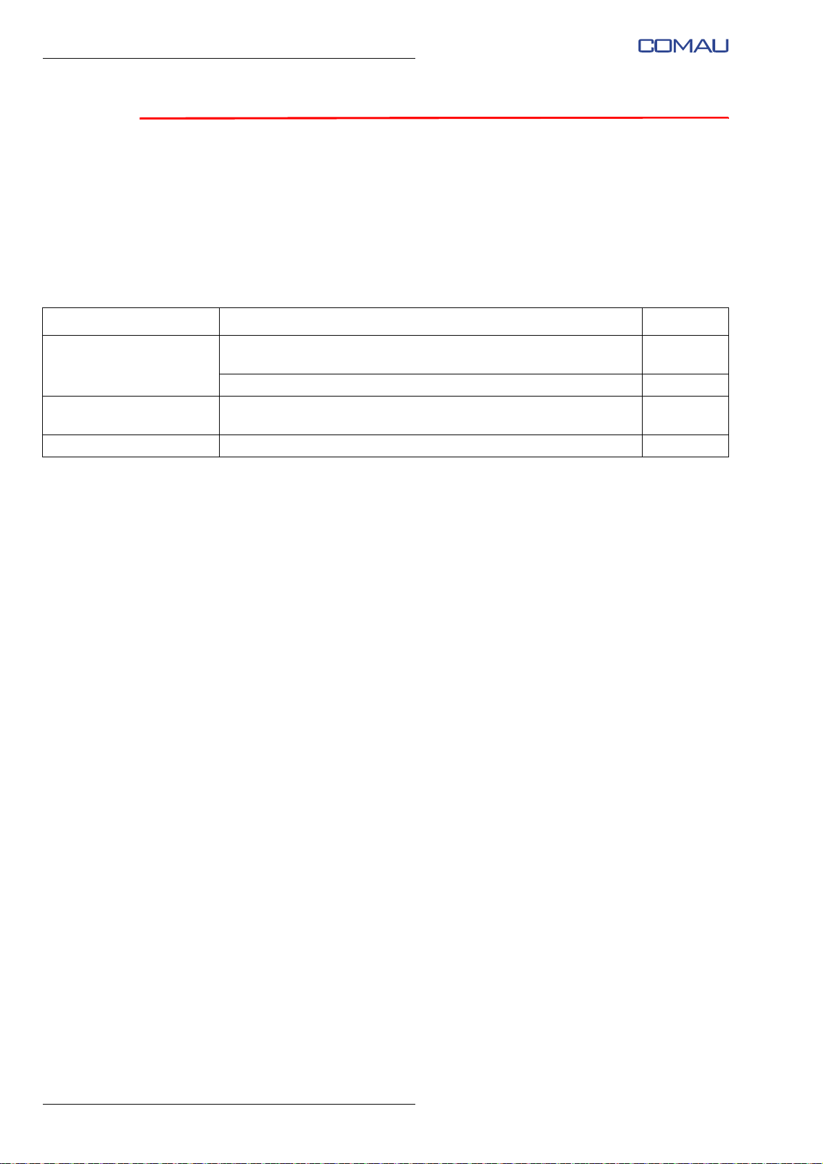
Tab. 7.1 - Cleaning operations and periodic checks
When / how often Type of activity Paragraph
Before each use of the
Robot
At every power-up of the
Robot
After each use e.DO cleaning par. 7.2
Check the presence and conservation state of the warning signs
and labels
Check the correct fixing of the e.DO parts par. 7.1.2
Check the correct functioning of emergency push-buttons par. 7.1.3
par. 7.1.1
58
Page 59
Comau Robotics Product Instruction
E.DO CLEANING INSTRUCTIONS AND PERIODIC CHECKS
7.1 Periodic checks
– Check the presence and conservation state of the warning signs and labels
– Check the correct fixing of the e.DO parts
– Check the correct functioning of emergency push-buttons
7.1.1 Check the presence and conservation state of the w arning signs and labels
When is it necessary to check the warning signs and labels of e.DO?
The check of the warning signs and labels must be carried out before each use of the
Robot.
How to check the warning signs and labels of e.DO?
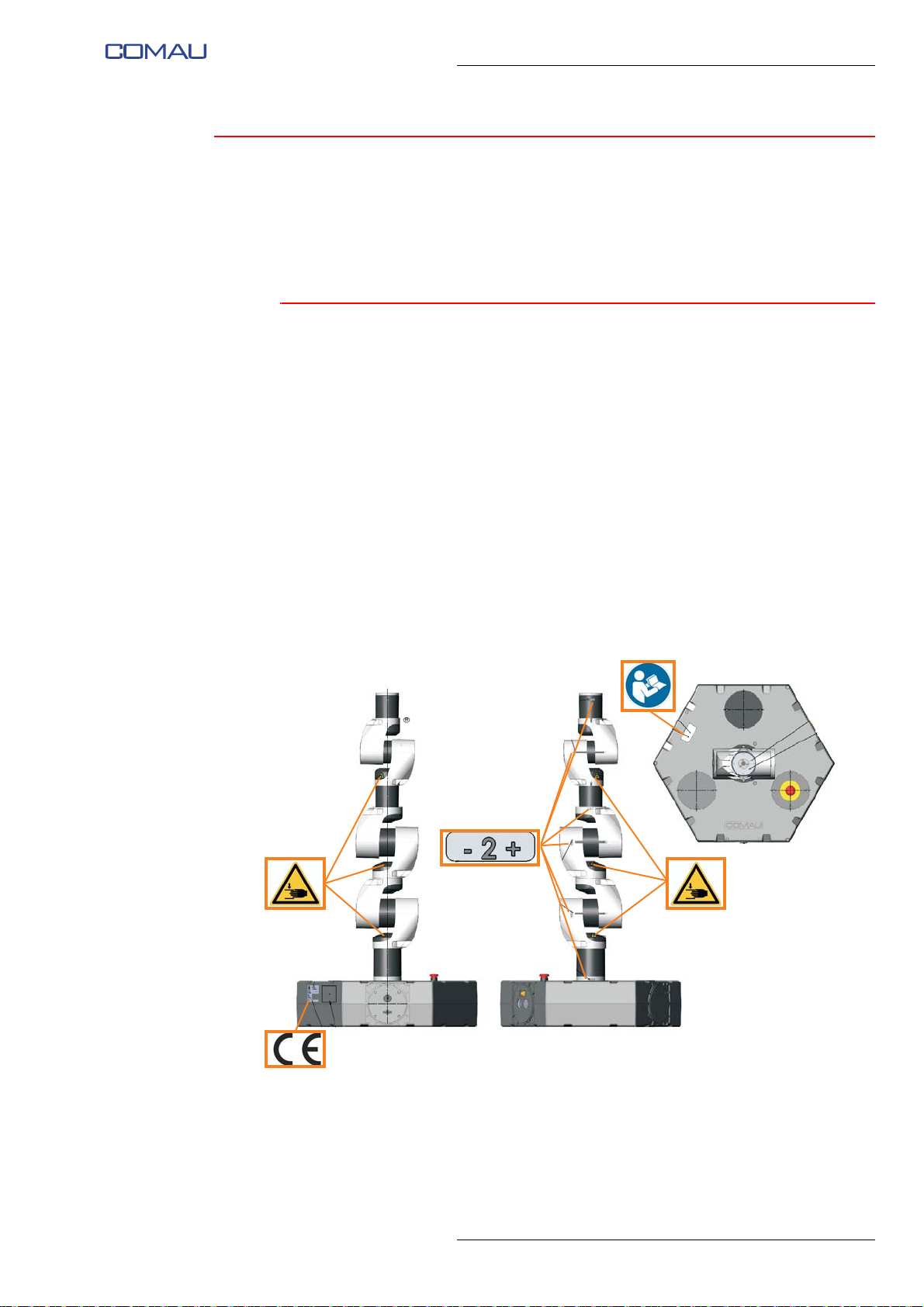
Check that the following warning signs and labels are present and clearly visible on the
Robot:
– “+” and “-” labels to identify the direction of rotation of the Robot axes;
– “pinching risk” labels on the Robot axes;
– “read the handbook” label on the Robot base;
– plate with CE marking on the Robot base.
59
Page 60

Comau Robotics Product Instruction
E.DO CLEANING INSTRUCTIONS AND PERIODIC CHECKS
7.1.2 Check the correct fixing of the e.DO parts
When is it necessary to check the correct fixing of the e.DO parts?
The check of the correct fixing of the e.DO parts must be carried out before each use of
the Robot.
How to check the fixing of the e.DO parts?
Check the correct fixing of:
– e.DO to its base;
– all caps and covers on the base of the Robot;
– all individual joints of the Robot and the corresponding support brackets;
– all perforated covers installed to cover the electronic boards of the Robot joints.
In the event that one or more parts of e.DO are not correctly fixed, do not use the Robot
and ensure correct tightening and fastening of loose or wobbly parts (for details, see the
Service Manual).
7.1.3 Check the correct functioning of emergency push-buttons
When is it necessary to check the correct functioning of the e.DO
emergency push-buttons?
The check of the correct functioning of the emergency push-buttons must be carried out
each time the Robot is powered up.
How to check the correct functioning of the e.DO emergency
push-buttons?
Check the correct functioning of the emergency push-buttons before starting the Robot
itself, as indicated below:
– power up the Robot;
– connect the tablet:
– reset the Robot emergency push-buttons by rotating them in the direction indicated
by the arrow;
– calibrate the Robot;
– press the emergency push-buttons, one at a time, and check that after pressing a
push-button, the “Unbrake” screen image is displayed on the tablet (need for the
execution of the Robot axis brake release);
– in this way, check the correct operation of all the emergency push-buttons present
on the Robot.
60
Page 61

7.2 e.DO cleaning
Before carrying out any cleaning operation, make sure that the Robot is powered off and
remove the plug from the power socket.
When is the e.DO cleaning required?
The general cleaning of e.DO must be performed at the end of each use.
In case of long periods of non-use, it is recommended to put e.DO inside the original
packaging or cover it appropriately with special sheets / nylon, to protect it from dust.
How to clean e.DO?
The general cleaning of e.DO must be performed using a soft bristle brush or soft damp
cloth. Do not use abrasive products, abrasive sponges, solvents or metal objects.
Carefully clean the Robot base and the related areas of the connectors; clean the
perforated plastic covers on each Robot joint. If not used, carefully clean the threaded
holes for tool installation present at the end of the Robot (Robot wrist flange).
Comau Robotics Product Instruction
E.DO CLEANING INSTRUCTIONS AND PERIODIC CHECKS
61
Page 62
Comau Robotics Product Instruction
GENERAL TECHNICAL FEATURES OF THE E.DO ROBOT
8.
GENERAL TECHNICAL FEATURES OF THE
E.DO ROBOT
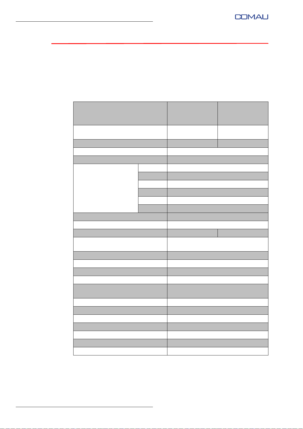
The following table lists the main Robot technical features:
Tab. 8.1 - e.DO Robot technical features
VERSION
Structure / No. of axes
Wrist load max 1 kg (2.2 lb) max 0.4 kg (0.88 lb)*
Torque of axis 4 - 5 - 6 2.75 Nm
Admissible inertia on axis 4 - 5 - 6 0.003 kgm²
Axis 1 ± 179° (23 °/s)
Axis 2 ± 99° (23 °/s)
Axis 3 ± 99° (23 °/s)
Stroke (Speed)
Axis 4 ± 179° (34 °/s)
Axis 5 ± 103.5° (34 °/s)
Axis 6 ± 179° (34 °/s)
Max horizontal reach 478 mm (1.56 ft)
Repeatability ± 1 mm
Robot weight 13.5 kg (29.8 lb) 13.7 kg (30.20 lb)
Robot tool coupling flange features See Diagram of holes on Robot flange for
Motors DC motors
Position measurement system Encoder 256 IMP
Protection degree IP2x
Robot colour White and black
Assembly position Horizontal plane, on the relative hexagonal
Operating environment temperature from +10 °C to +40 °C
Storage temperature from -10 °C to +55 °C
Relative humidity 5% to 95% without condensate
Maximum temperature gradient 1,5 °C/min
Power supply voltage / frequency 230 Vac / 50 Hz
Area of application and intended use Educational, mainly for didactic purposes
Noisiness < 70 dB(A)
* Limitation due to the maximum capacity load of the e.DO Gripper
e.DO with 6 axes
(central and side)
Anthropomorphic 6
axes
tool fixing in the Service Manual.
e.DO with 6 axes
with e.DO Gripper
(central and side)
Anthropomorphic 7
axes
base
62
Page 63

Comau Robotics Product Instruction
WARRANTY TERMS AND CONDITIONS
9.
WARRANTY TERMS AND CONDITIONS
The Robot warranty is exclusively related to malfunctions or damages of the Robot itself
caused by manufacturing defects or incidents of non-compliance and applies as long as
the Robot has been installed and used correctly, in full compliance with the technical
features indicated in the technical documentation and instructions.
To activate the Robot warranty it is necessary to register on the e.DO website, at
https://edo.cloud/.
As an example, outside the scope of the warranty are any malfunctions deriving from:
–
use of the Robot in environments with environmental specifications not suitable for
normal operation of the Robot itself (for details consult Chap. General
technical features of the e.DO Robot);
– cases of force majeure (such as lightning, particular atmospheric agents, etc.)
– modifications of electrical power supply conditions (including voltage and current
peaks
, etc.) that are higher than the limits set in the Robot technical
documentation;
mechanical, electrical, software modifications not authorized by the manufacturer
–
(details at par. 4.2 List of allowed and not-allowed operations, in order to preserve
the warranty on pag. 4-56 of the Service Manual);
performance of maintenance or repair operations not authorized by the
–
m
nufacturer and indicated in the Service Manual.
a
The Robot is subject to different warranty conditions, depending on the methods of sale,
as in
dicated below:
– Warranty conditions for B2B (Business-to-Business) sale
– Warranty conditions for B2C (Business-to-Customer) sale
63
Page 64

Comau Robotics Product Instruction
WARRANTY TERMS AND CONDITIONS
9.1 Warranty conditions for B2B (Business-to-Business) sale
In case of B2B sale, to the Robot shall be applied the following warranty conditions:
– the warranty has a duration of 24 months;
– the warranty period starts from the effective date of delivery of the Robot to the end
use
– return rights are not applicable;
– in case of need for technical assistance during the warranty period, the product
shi
shall be sent to the Customer directly by Comau, free of charge.
9.2 Warranty conditions for B2C
r or, if not available, the delivery date of the Robot to the courier;
pment costs are charged to the final Customer; after the assistance, the Robot
(Business-to-Customer) sale
In case of B2C sale, to the Robot shall be applied the following warranty conditions:
– the warranty has a duration of 24 months;
– the warranty period starts from the effective date of delivery of the Robot to the end
use
r or, if not available, the delivery date of the Robot to the courier;
– the possibility of Robot return within 15 days from the effective date of delivery is
pr
ovided; the Robot shall be put inside its original packaging;
– in case of need for technical assistance during the warranty period, the product
shi
pment costs are charged to the final Customer; after the assistance, the Robot
shall be sent to the Customer directly by Comau, free of charge.
64
Page 65

Page 66
MadeinComau
Original instructions
 Loading...