

Page 1

PRESSURE
TEST PUMP
OPERATOR MANUAL
Page 2

CONTENTS
1. INTRODUCTION . . . . . . . . . . . . . . . . . . . . . . . . . 2
1.1 Pressure Test Pump Kits . . . . . . . . . . . . . . . 4
1.2 Release Valve . . . . . . . . . . . . . . . . . . . . . . . . . 4
1.3 Volume Control. . . . . . . . . . . . . . . . . . . . . . . . 4
1.4 Over Pressure Protection . . . . . . . . . . . . . . . 5
1.5 Pressure/Vacuum Selection . . . . . . . . . . . . . 5
2. GUIDELINES FOR USE . . . . . . . . . . . . . . . . . . . 6
2.1 Calibration/Comparison against
Comark Digital Pressure Meter. . . . . . . . . . 6
2.2 Use with High Resolution Pressure
Ranges (1mBar) . . . . . . . . . . . . . . . . . . . . . . . 8
2.3 Fault Investigation . . . . . . . . . . . . . . . . . . . . 8
3. PERFORMING HYSTERESIS TESTS . . . . . . . 10
3.1 Increasing Pressure. . . . . . . . . . . . . . . . . . . . 10
3.2 Decreasing Pressure to Measure
Hysteresis . . . . . . . . . . . . . . . . . . . . . . . . . . . . 12
4. SPECIFICATION . . . . . . . . . . . . . . . . . . . . . . . . . 13
1
Page 3

1. INTRODUCTION
The pressure test pump is a dual portable source of
either vacuum or pressure supply. Each pump
incorporates a vacuum/pressure selector and a volume
control feature for fine adjustment.
WARNING
THE HAND PUMP IS CAPABLE OF GENERATING
PRESSURES IN EXCESS OF 200 PSI. TO
PREVENT DAMAGE IT IS ESSENTIAL NOT TO
OVER PRESSURE ANY GAUGE CONNECTED TO
THE PUMP.
2
Page 4
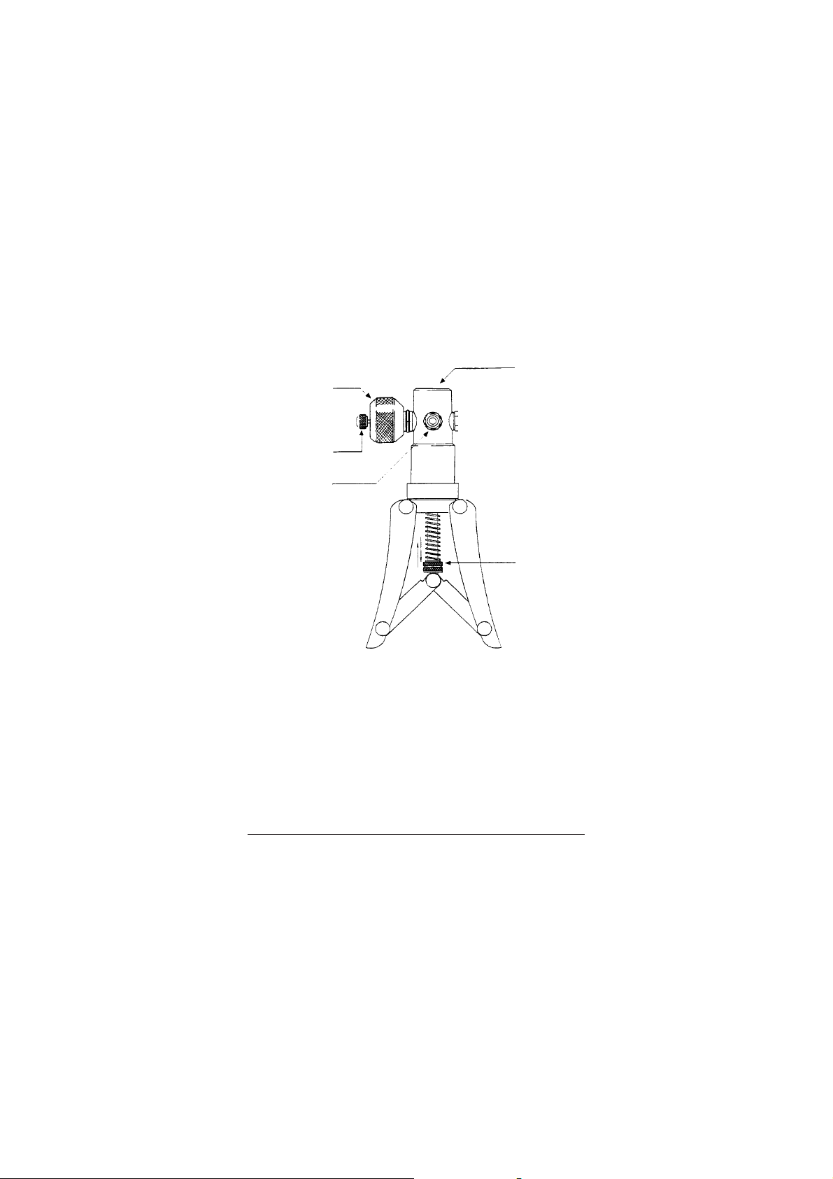
n
o
p
q
r
n Pressure port — 3/8" BSP Parallel female connection
o Fine adjustment valve
p Pressure release valve
q Pressure/vacuum selector
r Adjustable stroke for varying maximum pressure
output (over pressure protection)
3
Page 5

1.1 Pressure Test Pump Kits
The TK1 kit can be used with the Kane-May
KM5000 series and the TK2 kit with the C9500
series pressure meters and provides the capability
to set up and check the calibration of pressure
gauges, switches, pressure to current convertors
and other pneumatic instruments.
Note: Do not overtighten the hexagonal nut when
connecting the pressure meter tubing to the hand
pump or the pressure pump could be damaged.
1.2 Release Valve
This can be used to reduce or release the pressure
in the system. The rate of pressure reduction is
dependent upon the degree of rotation when
opening the valve. Minimal force is required to seal
the system. Excessive force may damage the
internal seals.
1.3 Volume Control
The pressure generated can be finely adjusted by
turning the volume control valve either clockwise
or anti-clockwise to increase or decrease pressure
accordingly.
IMPORTANT: Under no circumstances
should the volume control valve o be wound
back beyond the red line indicator on the
body. Should this occur, then the pressure
must be released from the system before
attempting to re-engage the volume control
valve.
4
pp
p
pp
oo
o
oo
Page 6
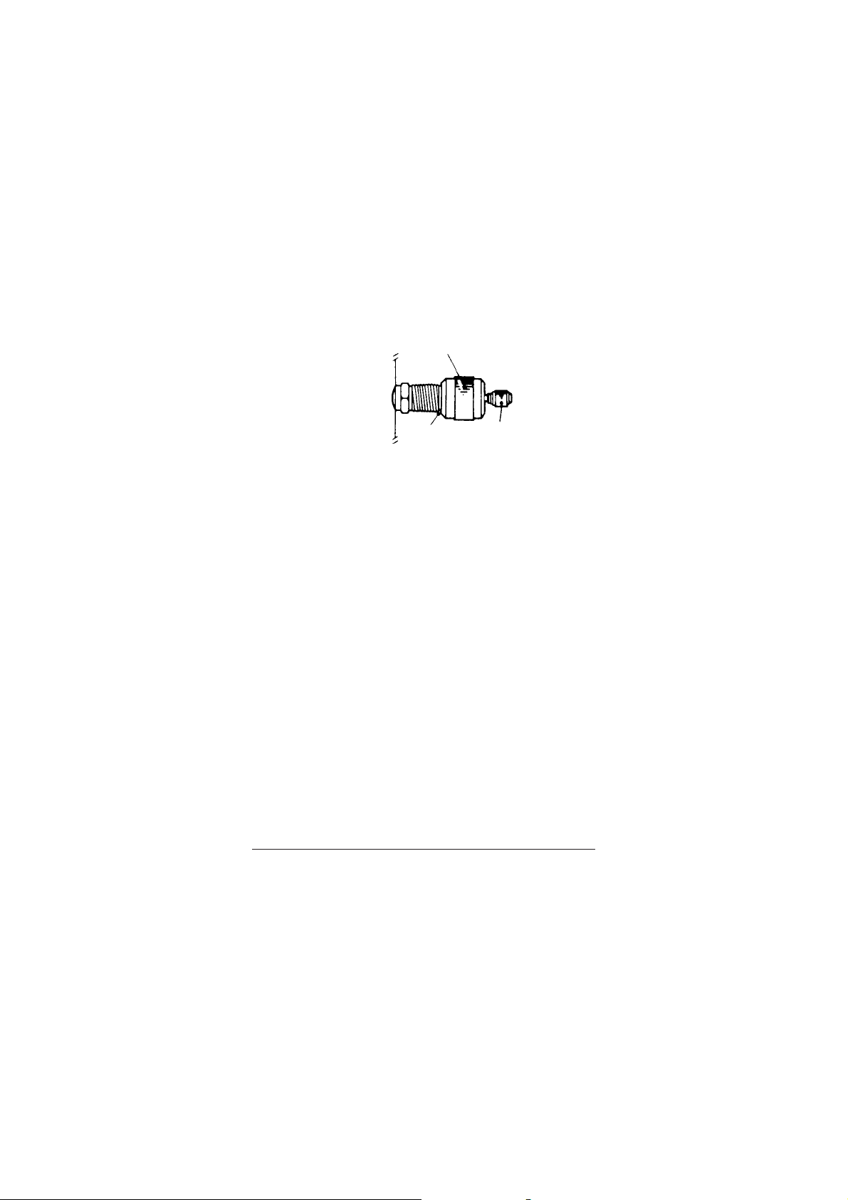
VOLUME CONTROL VAL VE
RED LINE
INDICATOR
RELEASE
VALVE
1.4 Over Pressure Protection
To adjust the maximum output pressure of the
system turn the nuts r to increase or decrease the
stroke length.
1.5 Pressure/Vacuum Selection
qq
q
qq
Press the selector q as indicated on the label to
engage the desired mode. Ensure that the release
valve p is fully closed (clockwise motion) prior to
pumping.
Notes:
1. The pump should only be used for pressurising
small volumes due to its small displacement.
2. If the pump has not been used for a period of
time, it could be difficult to operate on the
first stroke. This is due to the piston seal
drying slightly.
3. The cylinder has been lightly greased on
assembly but, if additional lubrication should
ever be required, then apply a minimal
amount to the inside of the cylinder. Access is
via the three retaining screws located under
the black collar.
For release valve seal replacement, please contact
Comark Service Department or your Distributor.
5
Page 7

2. GUIDELINES FOR USE
2.1 Calibration/Comparison against
Comark Digital Pressure Meter
(a) Fit KM5000 or C9500 instrument to test
pump.
(b) Connect gauge under test to pump choosing
correct adaptors and seals from the set
provided.
Note: Ensure both seals are fitted and
adaptors are tightened. (See paragraph 1.1).
(c) Screw volume control knob fully clockwise.
(d) Screw pressure release valve fully clockwise,
tightening to ensure good seal.
(e) Screw volume control knob 4–6 full turns
anti-clockwise.
(f) Operate handles until the pressure is close to
that finally required.
WARNING
ONE FULL SQUEEZE OF THE
HANDLES IS SUFFICIENT TO OVER
RANGE A COMARK 2 PSI METER. IF
THIS SHOULD OCCUR REDUCE THE
PRESSURE UNTIL A READING SHOWS
ON THE DISPLAY.
6
Page 8

(g) Wind volume control knob clockwise to
increase pressure or anti-clockwise to
decrease pressure until required pressure is
reached.
Note: The pressure may settle for up to
30 seconds after increasing pressure with
pump due to thermodynamic effects, settling
of seals and expansion of the flexible pipe.
CAUTION: NEVER screw volume
control knob anti-clockwise when red
band is showing.
(h) Reductions in pressure can be achieved by
careful use of the pressure release valve,
however this valve is not guaranteed to seal
fully unless the volume control knob is
screwed fully clockwise.
(i) Vacuum is achieved using procedure
identified above and having the changeover
valve pushed completely towards the vacuum
position.
Note: The changeover valve should never be
operated with the unit pressurised, only
when the pressure release valve is open.
Operation of this valve when unit is
pressurised causes an instantaneous release
of pressure which can damage the seals
within the pump.
7
Page 9

2.2 Use with High Resolution Pressure
Ranges (1mBar)
The higher resolution available will amplify the
visibility of the thermodynamic effects as
mentioned in paragraph 2.1(g). These should
however still settle to useable values within one
minute of pressurisation.
Note: On very high resolutions such as 1mBar or
0.1 inches of water, small movements of the pipe
may result in noticeable pressure changes.
2.3 Fault Investigation
In the event that the system appears to lose
pressure then the procedure above should be
repeated ensuring new seals are used, adaptors are
tightened sufficiently and the pressure release
valve is tightened firmly with the volume control
knob screwed fully clockwise.
Note: The connections to the hand held test pump
are sealed with nylon washers and should not leak.
The pipe to body connection can be checked but
tightened no more than 2Nm.
DO NOT attempt to tighten the other fitments to
the test pump as this could lead to breaking of
sealed joints.
When testing for leaks it may be noticed that air is
drawn in or expelled from around the changeover
valve. This is normal and should cause no concern.
8
Page 10

Some instruments include pressure relief valves to
protect the instrument. Before suspecting a leak in
the pump check the relief valve pressure is not
being exceeded and the relief valve is seated
properly. This can be achieved by substitution with
another gauge and retest for leaks.
9
Page 11

3. PERFORMING HYSTERESIS TESTS
The hand held test pump can be used with a high
resolution instrument to check accuracy and hysteresis
of a pressure measuring instrument.
3.1 Increasing Pressure
(a) Fit KM5000 or C9500 instrument to test
pump.
(b) Connect the gauge under test to pump
choosing correct adaptors and seals from the
set provided.
Note: Ensure both seals are fitted and
adaptors are tightened. (See paragraph 1.1).
(c) Screw the volume control knob fully
clockwise.
(d) Screw the pressure release valve fully
clockwise, tightening to ensure good seal.
(e) Screw the volume control knob 8–9 full turns
anti-clockwise.
(f) Operate the handles until the pressure is
slightly less than that finally required.
10
Page 12

WARNING
ONE FULL SQUEEZE OF THE
HANDLES IS SUFFICIENT TO OVER
RANGE A COMARK 2 PSI METER. IF
THIS SHOULD OCCUR REDUCE THE
PRESSURE UNTIL A READING SHOWS
ON THE DISPLAY.
(g) Wind the volume control knob clockwise to
increase pressure to the calibration point
and record readings.
Note: The pressure may settle for up to
1 minute after increasing pressure with
pump due to thermodynamic effects, settling
of seals and expansion of the flexible pipe. If
this is significant, operate the volume control
knob again to retain calibration pressure.
CAUTION: NEVER screw the volume
control knob anti-clockwise when red
band is showing.
(h) Repeat steps 3.1(f) and (g) for other
calibration points. If the volume control knob
does not have sufficient travel remaining,
screw it fully clockwise and return to
paragraph 3.1(e).
(i) When maximum calibration pressure has
been achieved and the results noted, proceed
to paragraph 3.2 — Decreasing Pressure.
11
Page 13

3.2 Decreasing Pressure to Measure Hysteresis
To correctly measure hysteresis it is important
that the pressure in the system never falls lower
than the calibration point next required.
(a) Carefully unscrew the release valve slightly
to allow the pressure to drop gently, but not
to fall below the next calibration point. Fully
tighten the release valve (clockwise).
(b) Screw the volume control knob fully
clockwise, repeating paragraph 3.2(a) if
maximum pressure is reached before volume
control knob is fully screwed in.
(c) Carefully unscrew the release valve slightly
to allow the pressure to drop close to the
next lowest calibration point ensuring that
the pressure does not fall below the
calibration point. Fully tighten the release
valve (clockwise).
(d) Wind the volume control knob anti-clockwise
until calibration pressure is reached and
record readings.
(e) Wind the volume control knob fully clockwise
(to ensure that the pressure release valve
can be tightened satisfactorily).
(f) Repeat paragraphs 3.2(c) to 3.2(e) for
remaining calibration positions.
(g) When test completed unscrew the pressure
release valve before removing either
instrument to ensure the system is not
pressurised.
12
Page 14

4. SPECIFICATION
Output Pressure 0 to 25bar (adjustable)
Output Vacuum 0 to –0.8bar/0 to –24inHg
Materials Bright nickel plated brass, clear
anodised aluminium
Adjustment Fine volumetric pressure/vacuum
adjuster
Dimensions 220mm (L) x 105mm (W) x 63mm (D)
Weight 650 grams
13
Page 15

141516
Page 16

Page 17

Page 18

Comark
52 Hurricane Way
Norwich, Norfolk, NR6 6JB England
Tel: 01603 (+44 1603) 256647
Fax: 01603 (+44 1603) 256644
E-mail: service@comarkltd.com
Website: www.comarkltd.com
Comark Instruments
PO Box 9090, Everett
WA 98206, USA
Tel: (503) 643 5204
Fax: (503) 644 5859
Email: sales@comarkUSA.com
Website: www.comarkUSA.com
© Comark Stock No. 16683 Issue 3
 Loading...