

Page 1

MainsPro
Mains Decoupling Protection
SW version 1.6.1
1 Document information 6
2 Introduction of Installation and Operation Guide 9
3 Installation data 11
Relay
4 User interface 19
5 Introduction of Application Guide 28
6 Important Steps of MainsPro utilization 30
7 TRIP and Fault Reset 31
8 Protective features 33
9 Application tips 40
10 Introduction of Reference Guide 44
11 Technical data 45
12 Appendix 50
Copyright © 2019 ComAp a.s.
Written byPetra Piclová
Prague, Czech Republic
ComAp a.s., U Uranie 1612/14a,
170 00 Prague 7, Czech Republic
Tel: +420 246 012 111
E-mail: info@comap-control.com, www.comap-control.com
Global Guide
Page 2

Table of contents
1 Document information 6
1.1 Clarification of notation 6
1.2 About this guide 6
1.2.1 Installation and Operation Guide 6
1.2.2 Application Guide 6
1.2.3 Reference Guide 6
1.3 Legal notice 6
1.4 Document history 8
2 Introduction of Installation and Operation Guide 9
2.1 Purpose of this manual 9
2.2 Confornity declaration 9
2.3 Warnings 10
2.3.1 Dangerous voltage 10
2.3.2 Adjust the setpoints 10
3 Installation data 11
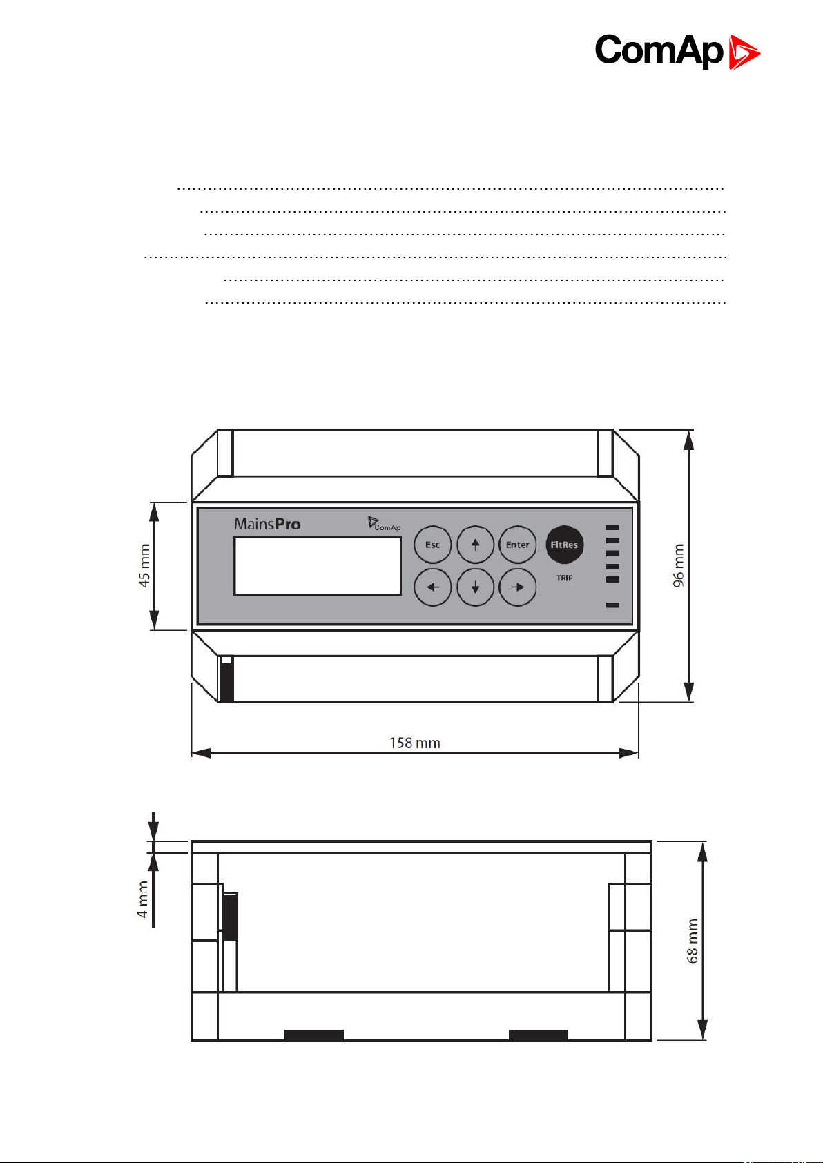
3.1 Dimensions 11
3.2 List of terminals 12
3.3 MainsPro Frame 12
3.4 Wiring 12
3.4.1 “Star” connection 13
3.4.2 “Delta” connection 13
3.4.3 Connection with voltage transformers 14
3.4.4 Single-phase connection 14
3.4.5 Power supply 15
3.4.6 Relay outputs connection 16
3.4.7 Binary switches connection 16
3.5 Measurement range 16
3.6 Wiring examples 17
4 User interface 19
4.1 Front panel elements 19
4.1.1 Pushbuttons 20
4.1.2 Setpoints change 20
4.1.3 Reset operation time 21
4.1.4 Reset trip counters 21
4.1.5 TEST mode activation 21
Mains pro 1.6.1 Global Guide
2
Page 3

4.1.6 Factory default 22
4.2 Mechanical sealing 22
4.3 Signalization LEDs 22
4.4 Measurement screens 24
4.5 Alarm messages 26
5 Introduction of Application Guide 28
5.1 Purpose of this manual 28
5.2 MainsPro typical usage 28
5.3 Typical applications of MainsPro protection relay 28
6 Important Steps of MainsPro utilization 30
7 TRIP and Fault Reset 31
7.1 TRIP 31
7.1.1 TRIP event 31
7.1.2 TRIP status 31
7.2 Fault reset 32
8 Protective features 33
8.1 ANSI 59 Overvoltage, ANSI 27 Undervoltage 33
8.2 Floating 10 minutes average overvoltage 34
8.3 ANSI 81H Overfrequency, 81L Underfrequency 34
8.4 ANSI 47 Voltage unbalance and angle asymmetry 36
8.4.1 Voltage unbalance 36
8.4.2 Positive sequence undervoltage, Negative sequence overvoltage 36
8.5 ANSI 78 Vector shift 37
8.5.1 Measuring principle 38
8.6 81R Rate Of Change Of Frequency (ROCOF) 39
8.7 Phase rotation, incorrect phase polarity 39
9 Application tips 40
9.1 Automatic return to mains 40
9.2 Binary switches 40
9.2.1 External trip 41
9.2.2 Fault reset 41
9.2.3 Alternative settings 41
9.2.4 Disable 41
9.2.5 CB Feedback 41
9.3 Counters 41
9.4 Timer 42
Mains pro 1.6.1 Global Guide
3
Page 4

9.5 Start trip 42
9.6 TEST mode 42
10 Introduction of Reference Guide 44
10.1 Purpose of this manual 44
11 Technical data 45
11.1 Accuracies and reaction times 45
11.1.1 Operating area 45
11.1.2 Voltage measurement 46
11.1.3 Frequency measurement 46
11.1.4 Time delays accuracy 46
11.1.5 Loss of Mains reaction times 46
11.2 Technical parameters 46
11.2.1 Endurance to the power supply voltage fails 47
11.3 Factory default setting of MainsPro unit 47
12 Appendix 50
12.1 Library of Setpoints 51
12.1.1 Group: Basic 52
12.1.2 Group: V <>, A.V <> 55
12.1.3 Group: dU, A.dU 56
12.1.4 Group: f <>, A.f <> 57
12.1.5 Group: LOM, A.LOM 58
12.1.6 Group: f(BI) 59
12.1.7 Group: f(RE) 60
12.2 Library of Binary switches 61
12.2.1 Ext Trip 61
12.2.2 Fault Reset 61
12.2.3 Alt Settings 61
12.2.4 Disable 61
12.2.5 CB Feedback 61
12.3 Relay outputs 62
12.3.1 CommTrpPer 63
12.3.2 !CommTrpPer 63
12.3.3 CommTrpImp 63
12.3.4 !CommTrpImp 63
12.3.5 CommSigImp 63
12.3.6 !CommSigImp 64
12.3.7 CommSigDel 64
Mains pro 1.6.1 Global Guide
4
Page 5

12.3.8 !CommSigDel 64
12.3.9 U Sig 64
12.3.10 !U Sig 64
12.3.11 f Sig 65
12.3.12 !f Sig 65
12.3.13 LOM Sig 65
12.3.14 !LOM Sig 65
12.3.15 dU Sig 65
12.3.16 !dU Sig 66
12.3.17 Other Sig 66
12.3.18 !Other Sig 66
12.3.19 Alt Sig 66
12.3.20 TrpEndImp 66
12.3.21 !TrpEndImp 67
12.3.22 InternFail 67
12.3.23 !InternFail 67
12.3.24 BakTrpPer 67
12.3.25 !BakTrpPer 67
12.3.26 BakTrpImp 68
12.3.27 !BakTrpImp 68
Mains pro 1.6.1 Global Guide
5
Page 6

1 Document information
1.1 Clarification of notation 6
1.2 About this guide 6
1.3 Legal notice 6
1.4 Document history 8
1.1 Clarification of notation
Note: This type of paragraph calls readers attention to a notice or related theme.
IMPORTANT: This type of paragraph highlights a procedure, adjustment etc., which can cause a
damage or improper function of the equipment if not performed correctly and may not be clear at
first sight.
Example: This type of paragraph contains information that is used to illustrate how a specific function
works.
1.2 About this guide
1.2.1 Installation and Operation Guide
The Installation and Operation Guide serves for the personnel providing installation of the MainsPro unit. It
contains wiring and setting instructions needed for service and commissioning of the unit. It also contains
introduction of the user interface and necessary procedures for setting and operation of the unit. Though
MainsPro is very simple and intuitive for the operating personnel, we recommend keeping one copy of this
manual available permanently at the site where MainsPro unit is installed, to facilitate the necessary service
and operation tasks.
1.2.2 Application Guide
The Application Guide serves for the designers and engineers, who process the necessary documentation and
implementation procedures on the site, where MainsPro is installed. It contains detailed description of MainsPro
functionalities and their practical application.
1.2.3 Reference Guide
The Reference Guide contains library of setpoints, inputs and outputs functionalities and detailed technical
information. This information is referenced in the Installation and Operation Guide and Application Guide.
1.3 Legal notice
This End User's Guide/Manual as part of the Documentation is an inseparable part of ComAp’s Product and
may be used exclusively according to the conditions defined in the “END USER or Distributor LICENSE
AGREEMENT CONDITIONS – COMAP CONTROL SYSTEMS SOFTWARE” (License Agreement) and/or in
the “ComAp a.s. Global terms and conditions for sale of Products and provision of Services” (Terms) and/or in
Mains pro 1.6.1 Global Guide
6
Page 7

the “Standardní podmínky projektů komplexního řešení ke smlouvě o dílo, Standard Conditions for Supply of
Complete Solutions” (Conditions) as applicable.
ComAp’s License Agreement is governed by the Czech Civil Code 89/2012 Col., by the Authorship Act
121/2000 Col., by international treaties and by other relevant legal documents regulating protection of the
intellectual properties (TRIPS).
The End User and/or ComAp’s Distributor shall only be permitted to use this End User's Guide/Manual with
ComAp Control System Registered Products. The Documentation is not intended and applicable for any other
purpose.
Official version of the ComAp’s End User's Guide/Manual is the version published in English. ComAp reserves
the right to update this End User's Guide/Manual at any time. ComAp does not assume any responsibility for its
use outside of the scope of the Terms or the Conditions and the License Agreement.
Licensed End User is entitled to make only necessary number of copies of the End User's Guide/Manual. Any
translation of this End User's Guide/Manual without the prior written consent of ComAp is expressly prohibited!
Even if the prior written consent from ComAp is acquired, ComAp does not take any responsibility for the
content, trustworthiness and quality of any such translation. ComAp will deem a translation equal to this End
User's Guide/Manual only if it agrees to verify such translation. The terms and conditions of such verification
must be agreed in the written form and in advance.
For more details relating to the Ownership, Extent of Permitted Reproductions Term of Use of the
Documentation and to the Confidentiality rules please review and comply with the ComAp’s License
Agreement, Terms and Conditions available on www.comap-control.com.
Security Risk Disclaimer
Pay attention to the following recommendations and measures to increase the level of security of ComAp
products and services.
Please note that possible cyber-attacks cannot be fully avoided by the below mentioned recommendations and
set of measures already performed by ComAp, but by following them the cyber-attacks can be considerably
reduced and thereby to reduce the risk of damage. ComAp does not take any responsibility for the actions of
persons responsible for cyber-attacks, nor for any damage caused by the cyber-attack. However, ComAp is
prepared to provide technical support to resolve problems arising from such actions, including but not limited to
restoring settings prior to the cyber-attacks, backing up data, recommending other preventive measures against
any further attacks.
Warning: Some forms of technical support may be provided against payment. There is no legal or factual
entitlement for technical services provided in connection to resolving problems arising from cyber-attack or
other unauthorized accesses to ComAp's Products or Services.
General security recommendations and set of measures
1. AccessCode
• Change the AccessCode BEFORE the device is connected to a network.
• Use a secure AccessCode – ideally a random string of 8 characters containing lowercase, uppercase letters
and digits.
• For each device use a different AccessCode.
2. Password
• Change the password BEFORE the device enters a regular operation.
• Do not leave displays or PC tools unattended if an user, especially administrator, is logged in.
3. Controller Web interface
Mains pro 1.6.1 Global Guide
7
Page 8

• The controller web interface at port TCP/80 is based on http, not https, and thus it is intended to be used only
in closed private network infrastructures.
• Avoid exposing the port TCP/80 to the public Internet.
4. MODBUS/TCP
• The MODBUS/TCP protocol (port TCP/502) is an instrumentation protocol designed to exchange data
between locally connected devices like sensors, I/O modules, controllers etc. From it’s nature it does not
contain any kind of security – neither encryption nor authentication. Thus it is intended to be used only in closed
private network infrastructures.
• Avoid exposing the port TCP/502 to the public Internet.
5. SNMP
• The SNMP protocol (port UDP/161) version 1,2 is not encrypted. Thus it is intended to be used only in closed
private network infrastructures.
• Avoid exposing the port UDP/161 to the public Internet.
1.4 Document history
Revision number Related SW Date of issue Author
9 1.6.1 26.4.2019 Petra Piclová
8 1.6.0 13.3.2018 Petra Piclová
7 1.5.0 16.1.2015 Petra Piclová
6 1.4.1 15.11.2013 Petra Piclová
5 1.4.0 30.10.2013 Petra Piclová
4 1.3.0 30.8.2012 Tomáš Jelen
3 1.2.0 20.4.2012 Tomáš Jelen
2 1.1.0 2.11.2011 Tomáš Jelen
1 1.0.0 18.6.2010 Tomáš Jelen
6 back to Document information
Mains pro 1.6.1 Global Guide
8
Page 9

2 Introduction of Installation and Operation Guide
2.1 Purpose of this manual 9
2.2 Confornity declaration 9
2.3 Warnings 10
6 back to Table of contents
Congratulations to your purchase of ComAp MainsPro unit! MainsPro is a microprocessor-based protective
relay, providing a comprehensive set of protective and supplementary functionalities. The basic protective
functions are:
Voltage
Frequency
Loss of mains
This covers the basic requirements for mains-decoupling (inter-tie, „G59/2“) protection, but allows also usage in
many applications where benefits of the unit’s unique functionality is needed.
2.1 Purpose of this manual
The Installation and Operation Guide serves for the personnel, providing installation of the MainsPro unit. It
contains wiring and setting instructions, needed for service and commissioning of the unit. It also contains
introduction of the user interface and necessary procedures to perform setting and operating of the unit. Though
MainsPro is very simple and intuitive for the operating personnel, we recommend keeping one copy of this
manual available permanently at the installation site, where MainsPro unit is installed, to facilitate the
necessary service and operation tasks.
2.2 Confornity declaration
Following described machine complies with the appropriate basic safety and health requirement of
the EC Low Voltage Directive No: 73/23 / EEC and EC Electromagnetic Compatibility Directive
89/336 / EEC based on its design and type, as brought into circulation by us.
The unit is certified to comply to the appropriate requirements of the standard DIN V
VDE V 0126-1-1 (certificate ref. 44 207 11 398020, available upon request), with the
following conditions:
The conformity with the Standard DIN V VDE V 0126-1-1, chapter 4.1/ 6.1,
VDE O126-1-1
which is declared in the certificate 44 207 11 398020, requires the tolerance
against one fault. In order to fulfill this functional safety requirement, a
redundant architecture has to be built by the usage of two certified units.
CEI 0-21
Mains pro 1.6.1 Global Guide
It has to be ensured that each of both units is connected to an output (relay)
which is capable to induce opening of the operated contactor.
The unit is certified to comply with the requirements of the standard CEI 0-21. The
9
Page 10

product MainsPro CEI 0-21 is set by default to cover the functionalities and default
limits requested by this certification. In line with this certification, the output
!CommTrpPer, set by default on the RE1 output of the unit, is to be used for opening
the circuit breaker in the connection point between generator and the mains.
2.3 Warnings
IMPORTANT: Be aware that the relay outputs can change state during and after the unit setting
(before the unit is used again ensure that the proper setting is done)!!!
IMPORTANT: Be aware that the devices connected to binary outputs of the unit may operate upon
disconnection of power supply, measurement inputs and/or binary inputs!!!
2.3.1 Dangerous voltage
In no case touch the terminals for voltage and current measurement!
Always connect grounding terminals!
In any case do not disconnect controller CT terminals!
2.3.2 Adjust the setpoints
All parameters are adjusted to their typical values. However the setpoints has to be checked and adjusted to
their real values before the first starting of the gen-set.
The following instructions are for qualified personnel only. To avoid personal injury do not perform any action not
specified in related guides for product.
Note: ComAp believes that all information provided herein is correct and reliable and reserves the right to
update at any time. ComAp does not assume any responsibility for its use unless otherwise expressly
undertaken.
6 back to Introduction of Installation and Operation Guide
Mains pro 1.6.1 Global Guide
10
Page 11
3 Installation data
3.1 Dimensions 11
3.2 List of terminals 12
3.3 MainsPro Frame 12
3.4 Wiring 12
3.5 Measurement range 16
3.6 Wiring examples 17
6 back to Table of contents
3.1 Dimensions
Mains pro 1.6.1 Global Guide
11
Page 12

3.2 List of terminals
BIC Binary inputs – COM terminal
BI1 – BI4 Configurable binary inputs
UA1 to 3
UB1 to 3
UC1 to 3
11, 21, 31, 41, 51 RE1-5 relay contact – common
12, 22, 32, 42, 52
14, 24, 34, 44, 54
L/+ Power supply – high range 85-265 VAC / 110 – 370 VDC
+ Power supply – low range 8 – 40 VDC. Connect “+” pole to this terminal
N/-
First set of voltage measurement terminals (UA).
Terminals UA1 and UA2 are internally interconnected
Second set of voltage measurement terminals (UB).
Terminals UB1 and UB2 are internally interconnected
Third set of voltage measurement terminals (UC).
Terminals UC1 and UC2 are internally interconnected
RE1-5 relay contact – normally closed
(during fault-free conditions maintained in open position)
RE1-5 relay contact – normally open
(during fault-free conditions maintained in closed position)
Common terminal for power supply.
In case of DC supply, connect “–“ pole to this terminal
3.3 MainsPro Frame
MainsPro Frame is a MainsPro accessory product, allowing door-mounting of the unit, direct access to the
keyboard and the screen without opening the switchboard, and additional shielding (IP 55) for the front panel.
The frame size is 230x180x34 mm.
3.4 Wiring
3.4.1 “Star” connection 13
3.4.2 “Delta” connection 13
3.4.3 Connection with voltage transformers 14
3.4.4 Single-phase connection 14
3.4.5 Power supply 15
3.4.6 Relay outputs connection 16
3.4.7 Binary switches connection 16
Mains pro 1.6.1 Global Guide
12
Page 13
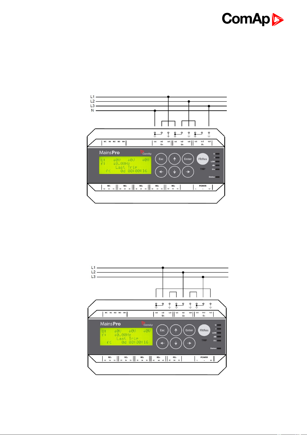
3.4.1 “Star” connection
If used for rated voltage 230 VAC ph-ground, set the setpoint Uin (page 52) to 230 V, for systems with rated
voltage 120VAC ph-ground, set the setpoint Uin (page 52) is to 120V. No additional setting is necessary for
indication of “Star” connection - MainsPro provides automatic detection of phase-ground voltage measurement.
MainsPro provides over-range to 130% of the rated voltage, i.e. 300 VAC for 230 V system and 156 V for 120 V
system with no change of measurement accuracy.
3.4.2 “Delta” connection
In this arrangement, MainsPro is rated for 400 VAC ph-ph with over-range to 130% = 520 VAC with no change of
measurement accuracy. Setpoint Uin (page 52) is to be set to 400 V, no additional setting is necessary for
indication of “Delta” connection. MainsPro provides automatic detection of phase-phase voltage measurement.
Mains pro 1.6.1 Global Guide
13
Page 14
3.4.3 Connection with voltage transformers
MainsPro allows connecting HV or other measurement transformers with secondary rated voltage 100V.
Provide the "Star" or "Delta" arrangement on the primary windings of the transformers and connect the
secondary 100 V to the MainsPro measurement inputs. Setpoint Uin (page 52) is to be set to 120V. This setting
provides the guaranteed measurement accuracy for the 100V inputs with overrange to 120V * 130% = 156 VAC.
Note: It is recommended to use “Delta” arrangement on the HV side to avoid nuisance tripping caused by phase
voltage unbalance.
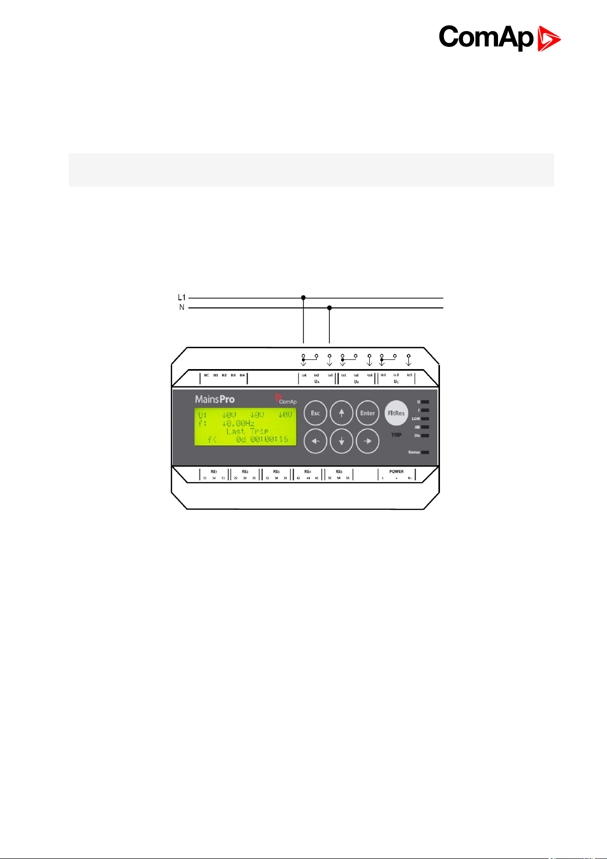
3.4.4 Single-phase connection
MainsPro provides support for single-phase applications. Use the UA terminals to connect the measured
voltage to the unit and set the setpoint System (page 52) to 1ph. Use the same setting of rated voltage
selection as mentioned above.
Mains pro 1.6.1 Global Guide
14
Page 15
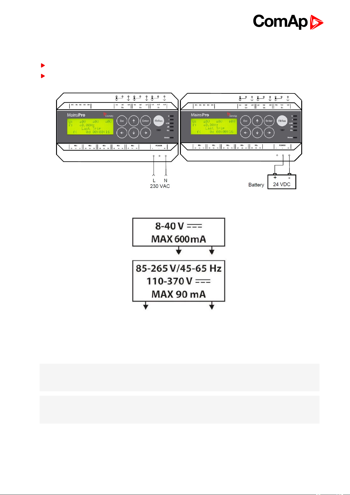
3.4.5 Power supply
MainsPro provides set of 3 terminals for the purpose of dual power supply range:
8 - 40 VDC: use the terminals + and N/-
85 - 265 VAC / 110-370 VDC: use the terminals L/+and N/-
For proper connection of the power supply, see also the printed sign on the MainsPro unit:
Requirements for power supply connections
The unit is suitable for permanent connection to the power supply. The power supply circuits must have
sufficient current withstand, corresponding to the appropriate power supply range and comply with the
standards relevant for the installation.
Note: External power supply is recommended in order to avoid excess of allowed supply voltage (256Vrms,
respectively 370V of peak value including dc offset).
Please be aware that not all power meters can detect the supply voltage including the dc component!
Note: The difference between power supply voltage and measured voltage must not exceed 1kV (peak-to-
peak), otherwise external power supply with appropriate voltage withstand is recommended to use. For
isolated, ungrounded systems external, galvanically isolated power supply is recommended in all cases.
Mains pro 1.6.1 Global Guide
15
Page 16

Requirements for power supply disconnecting device:
In case of power supply from AC voltage, the unit must be equipped by circuit breaker or contactor, marked as
disconnecting device in accordance with the EN 61010-1 standard.
Note: The power supply circuit 8-40 VDC is internally interconnected with the supply circuit 85-265 VAC. In
case of operation with both power supply terminals connected, keep in mind, that a failure of insulation in the
AC power supply may cause propagation of AC voltage into the circuits of low safe DC voltage, due to galvanic
interconnection of both circuits!
3.4.6 Relay outputs connection
For safety purposes, it is recommended to set all MainsPro relay outputs to inverse logic for failure trips and
signaling. This means that under fault-free conditions all contacts are kept in energized position. In trip or out-of-
range signaling state, the contacts de-energize. In case of power-supply fail, the unit automatically moves to
fault-signaling by de-energizing the output relays, assuring safety disconnection of the controlled devices.
These outputs are marked with exclamation mark (i.e.!CommTrpPer).
However, the outputs can be set to normal logic which means, that in fault-free state all contacts are kept in de-
energized position. In trip or out-of-range signaling state, the contacts energize. These outputs are without
exclamation mark (i.e.CommTrpPer).
Relay outputs in MainsPro are freely assignable by the setpoints f(RE).
In default configuration, RE1 serves as the permanently energized common trip output contact
(!CommTrpPer (page 63)). Use this contact to operate the connector devices with permanently energized
inputs.
In default configuration, RE2 serves as an impulse common trip contact (CommTrpImp (page 63)). Use
this contact to operate e.g. opening or UV coil of circuit breakers.
Remaining 3 relay outputs serve for signaling of any sensed failure.
The arrangement of RE1 to 4 outputs in default configuration corresponds to the functionality of the previous
NPU-FUV unit outputs.
3.4.7 Binary switches connection
MainsPro provides 4 galvanically isolated binary switches with configurable functionality. These inputs allow
connection of any voltage free contact between the common terminal BIC and the appropriate functional contact
(BI2 – BI4).
Particular functions (External Trip, Fault Reset, Alternative settings, Disable, CB Feedback) are freely
assignable by setpoint in Group: f(BI) (page 59).
For full description see Library of Binary switches on page 61.
3.5 Measurement range
MainsPro allows using multiple voltage ranges on the measurement inputs with unchanged measurement
accuracy. The following ranges are applicable:
230 V - this range applies in case of "star" connection of the 3-phase system using nominal 230V phase to
neutral. It may be also used for single-phase applications 230V phase to neutral. Overshoot by 30% up to
290V is possible for this measurement range. For this case, set the setpoint Uin (page 52) to 230/400V.
MainsPro will adjust automatically the measurement method, to assure the defined accuracy for the
measured voltage 230 V.
Mains pro 1.6.1 Global Guide
16
Page 17
400 V - this range applies in case of "delta" connection of the 3-phase system using nominal 400V phase to
phase. Overshoot by 30% up to 520V is possible for this measurement range. For this case, set the setpoint
Uin (page 52) to 230/400V. MainsPro will adjust automatically the measurement method, to assure the
defined accuracy for the measured voltage 400 V.
120 V - this range is applicable in countries using 120 V nominal voltage phase to neutral. Another
application is for the high-voltage and other applications, using voltage transformers from rated voltage to
100 V. The guaranteed accuracy applies to both ranges 100 and 120 V. Overshoot by 30% up to 156V is
possible for this measurement range. For this case, set the setpoint Uin (page 52) to 120V.
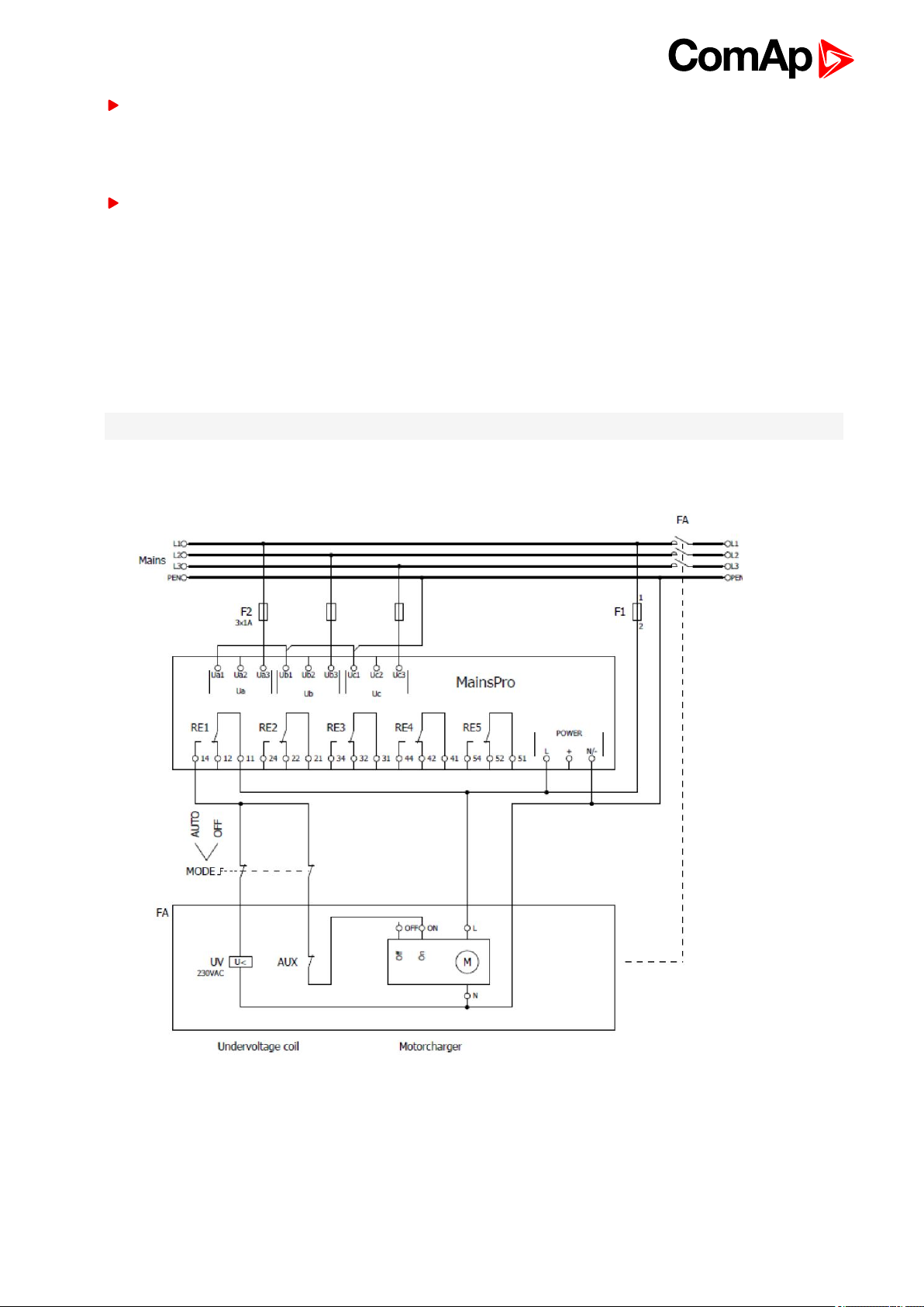
3.6 Wiring examples
This chapter provides examples of possible wiring of MainsPro which can be used as a preparation concept of
wiring scheme.
Note: ComAp bears no responsibility of functionality of the solution where these concepts are applied.
1. Under normal conditions the undervoltage coil is powered. In case of fault, the voltage is lost and the breaker
undervoltage coil opens.
2. Under normal conditions the Off coil is not powered and contacts are open. In case of failure, the contacts
(12) close and the voltage is applied on the Off coil, therefore auxiliary power supply (e.g.UPS) is necessary
to provide voltage for the Off coil.
Mains pro 1.6.1 Global Guide
17
Page 18
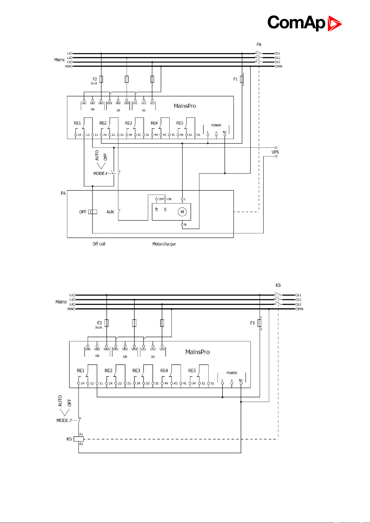
3. Under normal conditions the contacts are closed, in case of failure the contacts open. This wiring is typically
used for coil driven contactors.
6 back to Installation data
Mains pro 1.6.1 Global Guide
18
Page 19
4 User interface
4.1 Front panel elements 19
4.2 Mechanical sealing 22
4.3 Signalization LEDs 22
4.4 Measurement screens 24
4.5 Alarm messages 26
6 back to Table of contents
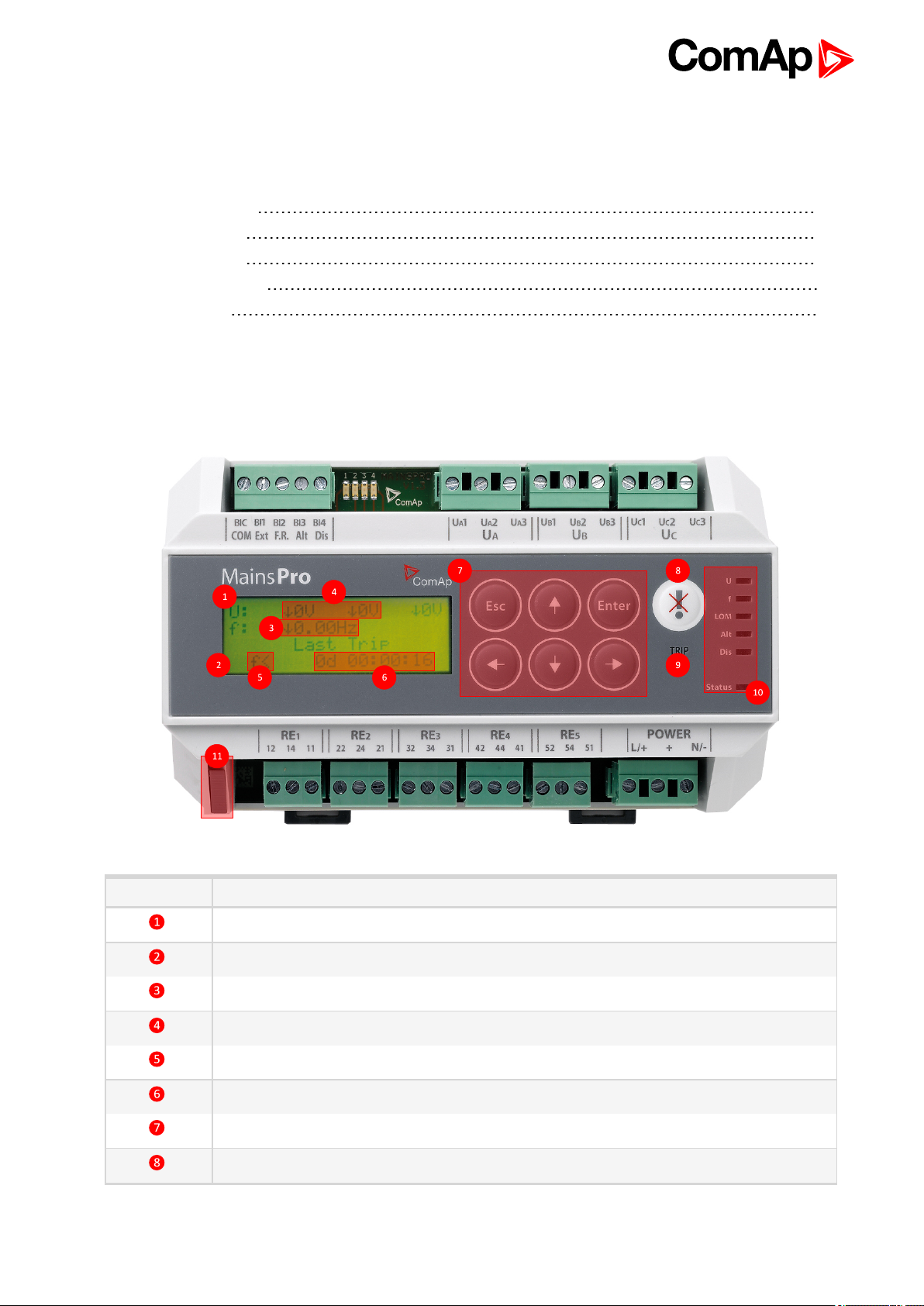
4.1 Front panel elements
Number Description
4 x 20 Alpha-numerical display
Mechanical sealing indication
Frequency measurement
3-phase voltage measurement
Last trip indication
Last trip timer
Control and navigation pushbuttons
Fault Reset button
Mains pro 1.6.1 Global Guide
19
Page 20

Number Description
TRIP LED
Singalization LEDs
Mechanical seal
4.1.1 Pushbuttons
In the measurement screens, use the ↑ and ↓ arrow buttons to browse through the measured values as
displayed on the 4x20 alphanumerical display. See the chapter Measurement screens (page 24) to get the
basic orientation.
To enter the setpoints menu, push the → button. For setpoints change, see Setpoints change on page 20.
To enter the init screen, to reset operation time, perform factory default reset, reset statistics or enter the
Test mode, push the ENTER and ESC at the same time. Together with the init screen display, the unit
performs lamp test by simultaneous cycling of all LEDs through all indication colors.
For confirmation of any value change or query, use the ENTERbutton.
For leaving any value change or query screen without change, use ESC button.
From any screen, press and hold the ESC button for 2 seconds to return back to the main measurement
screen (homepage).
4.1.2 Setpoints change
1. Push the → button to open the setpoints menu.
2. By buttons ↑ and ↓ browse through the menu. The setpoint groups are displayed in the cycling order, i.e.
from the last setpoint group by button ↓, the cursor moves to the first group and vice versa.
3. By button → or ENTER, enter the setpoint group, by button ←, move one level up in the setpoint tree. The
setpoints are displayed in the cycling order, i.e. from the last setpoint by button ↓, the cursor moves to the
first one and vice versa.
4. If standing on a setpoint, the setpoint change screen opens by pressing ENTER or →. In the screen, see the
setpoint limits at the lowest row of the screen.
5. The change is done by orders, starting from the least important digit. Use the buttons ← and → to move
between the digits. Use the buttons ↑ and ↓ to edit the digit. Please note, that the value is not limited by the
parameters limits during editing, but if an out-of-limits value is set-up, it will not be allowed to store in the unit
memory (the change may not be confirmed).
6. After the setpoint change is done, press ENTER to confirm the set value, or ESC to leave the setpoint
change screen without saving the changes.
Note: The unit allows mechanical sealing of the setpoints by the black switch in left-bottom corner of the unit. If
locked, the icon of closed padlock will appear on the position of setpoint change and the setpoints may not be
changed. Also, the padlock icon will be seen on the “homepage” measurement screen. Once the setpoint
change screen is entered and afterwards the sealing position is changed, the padlock indication is not changed,
but the internal lock is applied immediately.
Mains pro 1.6.1 Global Guide
20
Page 21

4.1.3 Reset operation time
1. Enter the init screen, by pushing the ENTER and ESC at the same time.
2. Press ← to enter the Reset Oper.Time? screen:
3. Using ← and → do your selection. By selecting YES, “Operation Time" timer will be reset, and the last five
events will be deleted. Press ENTER to confirm your selection.
4. By selecting NO and pressing ESC or by pressing ESC, return to the measurement screens with no change.
4.1.4 Reset trip counters
1. Enter the init screen, by pushing the ENTER and ESC at the same time.
2. Press ← to enter the Clear Statistics dialog screen:
3. Using ← and → do your selection. By selecting YES, all trip counters will be reset. Press ENTER to confirm
your selection.
4. By selecting NO and pressing ENTER or by pressing ESC, return to the measurement screens with no
change.
4.1.5 TEST mode activation
1. Enter the init screen, by pushing the ENTER and ESC at the same time.
2. Press ← and → to enter the Test mode activation screen:
3. Using ← and → do your selection. By selecting YES, you will activate the TEST mode - see the chapter
TEST mode (page 42) in Application Guide. Press ENTER to confirm your selection.
4. By selecting NO and pressing ENTER or by pressing ESC, return to the measurement screens with no
change.
Mains pro 1.6.1 Global Guide
21
Page 22

4.1.6 Factory default
MainsPro contains a default set of all setpoints, which corresponds to the typical requirement of distribution
network operator in some countries.
1. Enter the init screen, by pushing the ENTER and ESC at the same time.
2. Press ← and → to enter the Factory default activation screen:
3. Using ← and → do your selection. By selecting YES, you will return all previously done setting to the default
values. Please note that by this selection, you will lose all setting done prior to this operation!
Press ENTER to confirm your selection.
4. By selecting NO and pressing ENTER or by pressing ESC, return to the measurement screens with no
change.
4.2 Mechanical sealing
MainsPro allows to mechanically prevent the setting changes by securing the mechanical seal in locked
position by sealing wire. The locked position is indicated at the MainsPro side-print and on the alphanumerical
display.
4.3 Signalization LEDs
There are 7 LEDs for indication of MainsPro status with the meaning indicated in the table below
In case of signaling different statuses by one LED, the following priorities apply, i.e. the higher priority signal
is provided by the LED:
Red flashing
Red
Orange flashing
Orange
Green
Note: The U and f signalization is immediate at detection of fault conditions, regardless of the set delay for the
unit trip. After the conditions get back to the fault-free state, the LEDs may move back to green colour,
regardless of whether the unit is currently in TRIP status.
Indication of LED LOM is immediate at detection of the particular protection stage (Vector shift or ROCOF)
and fault indication remains active for the period of time, set by the setpoint Basic: Imp Len Del.
TRIP signalization is delayed according to the particular delay of the appropriate protective stage.
Mains pro 1.6.1 Global Guide
22
Page 23

Meaning of signaling LEDs
LED Color Meaning
TRIP
U
Red
Red
flashing
Nothing The unit has no output in TRIP position
Red
flashing
Red
Orange
flashing
Orange
Green All voltages are in fault-free state
Green
flashing
The unit has the appropriate outputs in TRIP position and the unit is
sensing a fault situation
The unit has the appropriate outputs in TRIP position, but the unit is
sensing fault-free situation. Fault reset is possible.
Voltage of any phase is above threshold for 1st or 2nd stage
overvoltage
Voltage of any phase is under threshold for 1st or 2nd stage
undervoltage
Voltage unbalance (amplitude) is indicated.
If activated together with LED f and LOM, indicates incorrect phase
rotation
Negative sequence overvoltage or Positive sequence undervoltage
is indicated.
If activated together with LED f and LOM, indicates incorrect
polarity of one phase
Floating 10 minutes average overvoltage (page 34) is detected
f
LOM
Nothing
Red
flashing
Red
Orange
flashing
Orange
Green Frequency, rotation and phases polarity are in fault-free state
Nothing
Red
Orange
flashing
Orange Together with LED U and f, indicates incorrect polarity of one phase
Over/under voltage protections are not enabled by setpoint and no
other voltage failure is sensed
Frequency as sensed on terminals Ua is above threshold for 1st or
2nd stage overfrequency
Frequency as sensed on terminals Ua is under threshold for 1st or
2nd stage underfrequency
Together with LED U and LOM, indicates incorrect phase rotation
Together with LED U and LOM, indicates incorrect polarity of one
phase
Over/under frequency is protections are not enabled by setpoint and
no other indicated failure is sensed
Vector shift or ROCOF protection was indicated and Fault reset
was not yet done
Together with LED U and f, indicates incorrect phase rotation
Mains pro 1.6.1 Global Guide
Nothing
None of Vector shift or ROCOF failure is detected or neither Vector
shift nor ROCOF protections are not enabled by setpoint and no
other indicated failure is sensed
23
Page 24

LED Color Meaning
Status
Alt
Dis
Red
flashing
Orange
flahing
Orange Indication of internal failure. Contact ComAp technical support!
Green The unit is in operation with no internal problems.
Nothing The unit is not in operation
Orange
Nothing The function Alternative setting is not activated
Orange The unit is disabled by means of binary switch Disable
Nothing The unit is not disabled by means of binary switch Disable
Indication of severe internal failure. Contact ComAp technical
support!
Indication of internal failure. Contact ComAp technical support!
The function Alternative setting is activated by means of binary
switch Alt setting.
4.4 Measurement screens
Following are the examples of the measurement screens, showing values measured and evaluated by the unit:
U: measured voltages on terminal sets
Ua, Ub and Uc. If overvoltage or
undervoltage is detected on a particular
Main measurement screen (homepage), 3-phase
application:
phase, arrow symbol is displayed left of
the particular voltage value.
f: measured frequency on terminal set Ua.
If overfrequency or underfrequency is
detected, arrow symbol is displayed left of
the frequency value.
Main measurement screen (homepage), 1-phase
application (setpoint System set to 1ph):
Loss of mains (LOM) measurement screen:
Last Trip: indication of the latest event,
which caused trip by the MainsPro unit.
See the following chapter for trip
messages explanation.
U: measured voltage on terminal set Ua. If
overvoltage or undervoltage is detected,
arrow symbol is displayed left of the
voltage value.
f: measured frequency on terminal set Ua.
If overfrequency or underfrequency is
detected, arrow symbol is displayed left of
the frequency value.
Last trip: indication of the latest event, that
caused trip by the MainsPro unit
Max Vs: maximum value of measured
Vector shift since unit power-up or since
the last reset Vector shift trip.
Mains pro 1.6.1 Global Guide
24
Page 25

Act RCF: actual measured value of
ROCOF protection
Max RCF: maximum value of measured
ROCOF protection since unit power-up or
since the last reset ROCOF trip.
V asymmetry: actual value of asymmetry
of effective values measured on terminals
Ua, Ub, Uc
Voltage asymmetry measurement screen:
Binary switches status screen:
Relay outputs 1-4 status screen:
V negative: actual value of negative
sequence voltage
V positive: actual value of positive
sequence voltage
Negative sequence overvoltage and positive
sequence undervoltage are methods of
evaluation of angle asymmetry of the 3-phase
voltage system. See more in the chapter
Voltage unbalance (page 36).
List of the assigned binary switches.
Functions that are configured are displayed in
the appropriate order.
Its status is displayed in brackets.
Status of the first 4 MainsPro relay
outputs.
Name in parenthesis marks the function
assigned by the setpoints in group f(RE).
Relay output 5 status screen:
Trip counters and indication screen:
Mains pro 1.6.1 Global Guide
Status of the 5th MainsPro relay output.
Name in parenthesis marks the function
assigned by the setpoints in group f(RE).
Last Trip: indication of the latest event,
which caused trip. See the following
chapter for trip messages explanation.
TripCnt: total counter of MainsPro trips
since the MainsPro unit counters reset
U: counter of overvoltage and
undervoltage -related trips
f: counter of overfrequency and
25
Page 26

Time measurement screen:
Trip history screen
underfrequency - related trips
LOM: counter of Loss-of-Mains - related
trips (Vector shift and ROCOF)
Otr: counter of trips with other reason than
the above mentioned: External trip,
voltage asymmetry, phase sequence or
inverse phase polarity
Operation Time: time since MainsPro was
powered up*
Last Trip Time: time of the latest trip since
MainsPro was powered-up
Please note that the time information on the
MainsPro unit is not measured by a calibrated
RTC device and may serve for orientation
purposes only. Find more in Technical data
(page 45).
List of last five trips - contains reason of the
trip and time since the unit was powered up
Note:
*For case of power cut off, the time stamp is stored and after the unit is powered up again, the timer will start
from the from following second after the last stored one.
4.5 Alarm messages
One of these indications appears on the homepage screen in case of the unit trip. It indicates the first protective
stage, which issued the trip event:
f> Overfrequency, 1st stage
f>> Overfrequency, 2nd stage
f< Underfrequency, 1st stage
f<< Underfrequency, 2nd stage
U> Overvoltage, 1st stage
U>> Overvoltage, 2nd stage
U< Undervoltage, 1st stage
U<< Undervoltage, 2nd stage
Vs Vector shift
RCF ROCOF
Vunb Voltage (amplitude) unbalance
Mains pro 1.6.1 Global Guide
26
Page 27

Vneg Negative sequence overvoltage
Vpos Positive sequence undervoltage
Vavg 10 minutes floating average overvoltage
Rot Wrong phase rotation
Pol Wrong polarity of one phase
Ext External trip
STr Start Trip
6 back to User interface
Mains pro 1.6.1 Global Guide
27
Page 28

5 Introduction of Application Guide
5.1 Purpose of this manual 28
5.2 MainsPro typical usage 28
5.3 Typical applications of MainsPro protection relay 28
6 back to Table of contents
5.1 Purpose of this manual
The Application Guide serves for the designers and engineers, who process the necessary documentation and
implementation procedures on the installation site, where MainsPro is installed. It contains detailed description
of MainsPro functionalities its practical application.
5.2 MainsPro typical usage
MainsPro is a mains protective relay protecting operation of parallel-to-mains generators or other electrical
resources of distributed generation of electricity. The main purpose is to prevent unwanted interaction between
the generator and mains in case of its abnormal state (e.g. mains failure):
Specific situations may occur, causing e.g. the utility network to momentarily disconnect part of the network
and connect it back by automatic-recloser. During this fault-clearing period, the generators may move away
from synchronism and their eventual re-connection may cause severe damage to the property of the
generator operator, or to the utility equipment.
The sole operation of a generator into an unintentionally islanded part of electricity network provides
potentially dangerous situation. The load of the area may exceed the generator capacity and cause
instability of the voltage, delivered to the consumers connected in the islanded area.
Severe hazards may occur to the working personnel on the grid equipment in the area, where the mains is
presumed as failed, but there are still generators delivering power into this area without central control of
their operation.
These are some of the situations, leading the utilities to strictly require that any parallel connection to the mains
is approved and protection devices with required protective features are installed.
5.3 Typical applications of MainsPro protection relay
These are installations of any sources of electrical energy. For example:
Cogeneration
Peak-lopping power stations
Stand-by generators with soft return/short-time parallel operation with mains
Microturbines
Mains pro 1.6.1 Global Guide
28
Page 29

Small hydro power-plant
Photovoltaic power plant
Windmills
6 back to Introduction of Application Guide
Mains pro 1.6.1 Global Guide
29
Page 30

6 Important Steps of MainsPro utilization
This process describes a typical decisions and technical steps to follow in case of MainsPro utilization, if
required by the distribution network operator (DNO).
Mains pro 1.6.1 Global Guide
30
Page 31

7 TRIP and Fault Reset
7.1 TRIP 31
7.2 Fault reset 32
6 back to Table of contents
7.1 TRIP
TRIP may be considered as event or status of the unit (see chapters bellow).
7.1.1 TRIP event
Starts in the moment of terminating the count-down of any protective function with delay, or in the moment of
activation of any immediate protective function.
As a result of the trip event, are e.g. the following consequences:
Immediate deactivation of outputs !CommTrpPer and !CommTrpImp or activation of CommTrpPer and
CommTrpImp
LED TRIP goes to red
The appropriate counter in the statistics screen increments
The cause of the TRIP event is recorded among the last five history events
The Last Trip Time timer starts to count time and the last trip indication is set
7.1.2 TRIP status
Starts at the moment of TRIP event
During this status, the appropriate outputs are kept in fault position
During this status, it is not possible to perform Fault reset
TRIP status is active until a successful Fault reset. This may not be done before all measured and evaluated
values are within preset limits.
If during the TRIP status, caused by some value, another value overreached its limits for TRIP evaluation,
this second overreach is not considered as TRIP. It does not cause a second TRIP event. However, as a
consequence of this, the TRIP duration may be prolonged until the moment when both (all) values are within
limits.
If the BI Disable is set to ENABLED and the BI Disable is activated during this state, the TRIP status is
terminated and the fault is reset.
If the BI Disable is set to ENABLEDexl.TRP and the BI Disable is activated during this state, it will have no
effect on the unit.
Mains pro 1.6.1 Global Guide
31
Page 32

7.2 Fault reset
Fault reset is an event, caused by one of the following reasons:
FltRes button is pressed
Binary switch Fault reset is activated
Automatic fault reset timer set by setpoint Auto FR Del [s] (page 53), has count down. The counter is
started in the moment when all evaluated values are back within their limits. If during the count-down another
fault status appears, the timer is reset and started no sooner than after all evaluated values are back within
limits again.
The above mentioned reasons are a trigger to provide Fault reset, however, it is successfully done only in case
that the TRIP status is activated and all evaluated values have returned back into limits. If the TRIP status is
not activated, or it is activated, but any of the values is still out of limits, Fault reset is not done and any of the
mentioned triggers is forgotten. I.e., the unit may not be „provisionally“ fault-reset.
By a successful Fault reset, the TRIP status is terminated.
6 back to TRIP and Fault Reset
Mains pro 1.6.1 Global Guide
32
Page 33

8 Protective features
The following protective functionalities, referred also by their ANSI number, are available in MainsPro unit:
8.1 ANSI 59 Overvoltage, ANSI 27 Undervoltage 33
8.2 Floating 10 minutes average overvoltage 34
8.3 ANSI 81H Overfrequency, 81L Underfrequency 34
8.4 ANSI 47 Voltage unbalance and angle asymmetry 36
8.4.1 Voltage unbalance 36
8.4.2 Positive sequence undervoltage, Negative sequence overvoltage 36
8.5 ANSI 78 Vector shift 37
8.5.1 Measuring principle 38
8.6 81R Rate Of Change Of Frequency (ROCOF) 39
8.7 Phase rotation, incorrect phase polarity 39
6 back to Table of contents
8.1 ANSI 59 Overvoltage, ANSI 27 Undervoltage
The RMS value of measured voltage is compared with the preset limit of overvoltage or undervoltage. When any
of the preset limits is over/underreached, the appropriate LED signal is issued by LED U and the output U Sig
moves to fault-indicating position immediately. If voltage of in the given phase keeps out of limits for the delay of
the appropriate stage, TRIP (page 31) is issued. As the voltage returns back within limits in all measured
phases, the LED and U Sig (page 64) output stop to signal the fault state immediately, regardless of whether
TRIP (page 31) was issued or not or Fault reset (page 32) was performed or not. Both overvoltage and
undervoltage protective stages provide possibility of setting 2 levels with independent delay assigned to each
level.
In order to prevent from unwanted voltage oscillation around the overvoltage, respective undervoltage limits,
there is a possibility to set up a voltage hysteresis. The principle is shown in the pictures below. After
overvoltage situation, voltage must decrease under the hysteresis limit to clear the fault. After undervoltage
situation, voltage must exceed the hysteresis limit to clear the fault.
Mains pro 1.6.1 Global Guide
33
Page 34

Image 8.1 Voltage hysteresis for overvoltage
Image 8.2 Voltage hysteresis for undervoltage
8.2 Floating 10 minutes average overvoltage
The unit calculates floating average of the measured voltage in each phase over 10 minutes interval. If any of
the three phase values overreaches the setpoint Avg V> [V] (page 55), TRIP (page 31) is issued, LED U
flashes and counter of voltage disturbances is incremented. As the Last Trip record, the message "Vavg" is
displayed. The protection stage is blocked for the first 10 minutes after power-up of the unit.
8.3 ANSI 81H Overfrequency, 81L Underfrequency
The frequency value measured on phase L1 is compared with the preset limit of overfrequency or
underfrequency. When any of the preset limits is over/underreached, the appropriate LED signal is issued by
Mains pro 1.6.1 Global Guide
34
Page 35

LED f and the output f Sig (page 65) moves to fault-indicating position immediately. If the frequency keeps out
of limits for the delay of the appropriate stage, TRIP (page 31) is issued. As the frequency returns back within
limits, the LED and f Sig (page 65) output stop to signal the fault state immediately, regardless of whether
TRIP (page 31) was issued or not or Fault reset (page 32) was performed or not.
Both overfrequency and underfrequency protective stages provide possibility of setting 2 levels with
independent delay assigned to each level.
Note: MainsPro measures frequency on the phase L1 only, therefore frequency measurement will be distorted
in case that a fault occurs in this phase.
In order to prevent from unwanted frequency oscillation around the overfrequency, respective underfrequency
limits, there is a possibility to set up a frequency hysteresis. The principle is shown in the pictures below. After
overfrequency situation, frequency must decrease under the hysteresis limit to clear the fault. After
underfrequency situation, frequency must exceed the hysteresis limit to clear the fault.
Image 8.3 Frequency hysteresis for overfrequency
Mains pro 1.6.1 Global Guide
35
Page 36

Image 8.4 Frequency hysteresis for underfrequency
8.4 ANSI 47 Voltage unbalance and angle asymmetry
MainsPro provides 3 independent methods for evaluation of voltage symmetry failures. All of these protections
are only active in case that 3-phase system is selected by the setpoint System (page 52).
8.4.1 Voltage unbalance
In further text, this term refers to the state, when amplitude difference between any 2 phases overreaches the
preset limit V unb, A.V unb [V] (page 56). I.e., it refers to the amplitude unbalance of the measured voltage.
8.4.2 Positive sequence undervoltage, Negative sequence overvoltage
These two methods provide very good sensitivity also to angle asymmetry of the measured voltages. The
evaluation is based on the mathematical principle of evaluation of the symmetrical components of measured
voltage. Any 3-phase system in any asymmetrical arrangement may be decomposed to 3 perfectly symmetrical
components:
Positive sequence - system of 3 phases with 120° phase-shift between the system vectors and the same
phase-order as the original system.
Negative sequence - system of 3 phases with 120° phase-shift between the system vectors and opposite
phase-order as the original system.
Zero sequence - system of 3 conphase vectors (with 0° phase-shift between the phases).
Mains pro 1.6.1 Global Guide
36
Page 37

Image 8.5 Decomposition of a generic 3-phase voltage to symmetrical components
MainsPro provides positive and negative sequence voltage evaluation and compares the measured values with
V> neg, A.V> neg [V] (page 57) and V< pos, A.V< pos [V] (page 56) thresholds. In the perfectly
symmetrical arrangement, negative sequence voltage is zero and positive sequence voltage equals to the
measured voltage. If the asymmetry situation occurs, non-zero negative sequence voltage is calculated and
positive sequence voltage drops. When any of the preset limits is over/underreached, the appropriate LED
signal is issued by LED U and the output dU Sig (page 65) moves to fault-indicating position immediately. If
the calculated values keep out of limits for the delay dU del, TRIP (page 31) is issued. As the calculated values
of voltage asymmetry return back within limits, the LED and dU Sig (page 65) output stop to signal the fault
state immediately, regardless of whether TRIP (page 31) was issued or not or Fault reset (page 32) was
performed or not. Some utilities strictly require in their regulations that symmetrical components are evaluated in
the mains-decupling relay and appropriate trip is provided. However, the method may also be used in the areas,
where no such requirement is in place, to minimize non-detection zones of detection of 1-phase mains failures.
In case that the generator, connected to the mains is operated close to equity-state, i.e. power delivered to the
mains is close to zero, it may be difficult to sense loss of one phase further in the system. The only change seen
in such situation may be movement of the failed phase by a certain angle with small or no voltage drop in the
absolute values. This may not be detected by undervoltage or unbalance protection stage. Symmetrical
components provide very good and sensitive method to detect such a situation and trip the generator in case of
this situation.
Typical setting of the V< pos vary from 0,65 to 0,85 of the rate voltage value. The exact values are delivered by
the mains operator or may be set-up during commissioning after experimental verification of the protection stage
sensitivity to the single-phase failures in equity state of the generator (e.g. by opening one fuse on the mains
transformer).
Note: If the phase L1 occurs a rapid voltage drop from 230V to e.g. 50V, tripping times might be longer and can
reach 100ms.
8.5 ANSI 78 Vector shift
The vector shift is one of the fast "Loss of Mains" protection stages. The principle is based on the fact that if a
generator works into an islanded area of the electricity network, its voltage and frequency depend strongly on
the load size, remaining in the islanded area. Decrease of the generator speed due to overload may not be fast
enough to assure e.g. trip by underfrequency stage. The mains may be equipped with auto-reclosing
mechanisms and in case that the generator is not disconnected within the auto-reclosing delay, the area may be
reconnected back to the grid by this mechanism. This reconnection may meet the generator in asynchronous
state, imposing severe risk of damage to the generator, its feeder equipment as well as equipment of the mains
operator. Vector shift provides fast protective function for this situation.
Mains pro 1.6.1 Global Guide
37
Page 38

8.5.1 Measuring principle
When synchronous alternator is loaded, the rotor displacement angle is built between the terminal voltage
(mains voltage) g and the synchronous electromotive force e. Therefore a voltage difference ΔU is built
between e and g. The rotor displacement angle between stator and rotor is depending on mechanical
moving torque of the generator shaft. The mechanical shaft power is balanced with the electrical feeder mains
power and therefore the synchronous speed keeps constant.
Image 8.6 In parallel with the mains
In case of mains failure or auto reclosing the generator suddenly feeds a very high consumer load. The rotor
displacement angle is decreased repeatedly and the voltage vector g changes its direction to g’.
Image 8.7 At mains failure
As shown in the timing diagram the voltage jumps to another value and the phase position changes. This
procedure is called phase or vector surge. MainsPro continuously measures the cycles, starting each zero up
ward slope. The time cycle is internally compared to the reference time. In case of vector surge the zero up ward
is delayed and the device trips instantaneously. The trip angle Δ and consequently the sensitivity of the vector
surge detection is adjustable by the setpoint VS lim, A.VS lim [°] (page 58).
Mains pro 1.6.1 Global Guide
38
Page 39

Proper setting of Vector shift limit has to be examined at the field tests, especially at very low setting of the
protection limit (under 3°). Vector shift is very fast method and may be sensitive to disturbances, naturally
present in the electricity grid.
Note: Due to high sensitivity, Vector shift protection is not evaluated in the transient states, e.g. when Alt
settings functionality is turned on or off, Fault reset (page 32) is performed or Vector shift limit is being set.
Functionality is blocked in the sine wave period, when such an event occurs.
8.6 81R Rate Of Change Of Frequency (ROCOF)
ROCOF is another fast "Loss of Mains" protection stages provided in MainsPro. It is based on the similar
principle as Vector shift, i.e. dependence of the generator speed and voltage on the load size. The variations of
frequency delivered by the gen-set depend on the load fluctuations and speed of the compensated fuel inlet. In
case of operation in parallel with large network, these changes are absorbed in the network and frequency is
stable. When the connected area disconnects from the mains into island operation, the frequency becomes
instable. MainsPro ROCOF stage provides fast evaluation of the frequency instability and TRIPS immediately
in case of fast frequency changes. The threshold is set by the setpoint ROCOF, A.ROCOF [Hz/s] (page 58).
As the ROCOF stage provides very sensitive protection, software filter may be set using the LOM: ROCOF filt
setpoint. By appropriate setting of those two setpoints, perfect ratio between sensitivity and speed of reaction of
ROCOF protection may be established at the field tests.
Note: ROCOF is sensitive to voltage jumps, therefore it is recommended to be disabled during tests of
overvoltage and enabled after tests are finished.
8.7 Phase rotation, incorrect phase polarity
MainsPro provides check of the phase sequence and polarity. The correct connection is indicated in the wiring
instructions e.g. on MainsPro box or in chapter Wiring (page 12), where clockwise rotation system is expected
on the mains side. It may happen, that e.g. by redesign in the mains or generator site installation, the phase
rotation changes. MainsPro ensures in such case, that this state is indicated and it prevents incorrect closing of
the circuit breaker by its standard protective functionality. To allow phase sequence or incorrect phase polarity
check, the phase angle between the 3 voltage vectors is expected in range 120° +/- 30°. If wrong phase
arrangement is detected, TRIP (page 31) is issued and the appropriate LED signalization is given. The
reconnection of measurement terminals is necessary to ensure further proper functionality of the unit.
6 back to Protective features
Mains pro 1.6.1 Global Guide
39
Page 40

9 Application tips
9.1 Automatic return to mains 40
9.2 Binary switches 40
9.3 Counters 41
9.4 Timer 42
9.5 Start trip 42
9.6 TEST mode 42
6 back to Table of contents
9.1 Automatic return to mains
Some utilities require that the protection unit provides an automatic return of the generating unit back to parallel
operation with mains. This automatic return usually does not happen immediately after the mains parameters
are within limits, but with pre-defined time delay. For such case, the unit allows setting a time delay during
which the Fault reset (page 32) can be automatically performed after the set time runs out.
Appropriate setting of automatic fault reset by setpoint Auto FR Del [s] (page 53) timer allows setting the
waiting time reserved for mains parameters to settle in their fault-free conditions after a TRIP (page 31). This
state is indicated by flashing red signal of the TRIP LED. If during this time any measured value reaches out of
the preset limits, MainsPro terminates the automatic fault reset count-down and goes back into fault indication
state. The automatic fault reset is reset and started again in the moment when all measured values are back in
limits again. After automatic fault reset is count down to zero, the unit performs automatic Fault reset (page 32)
and terminates the TRIP (page 31) status.
9.2 Binary switches
MainsPro allows basic remote operation by means of binary signals wired from an external logic to MainsPro
binary switches. The signals may be also provided remotely, e.g. through radio or GSM communicator devices.
As an example for the many similar devices on the market, see the uGATE communicator below. Ask for more
information about this product at protections@comap-control.com.
This way, MainsPro functionality may be simply controlled by a mobile telephone commands. All four binary
switches may be enabled or disabled by the appropriate setpoints in the group Basic.
Mains pro 1.6.1 Global Guide
40
Page 41

9.2.1 External trip
In case that a specific protective function is requested and this function is not supported in MainsPro, it may
be provided in an external device. Wire the output of this device to Ext Trip (page 61) to allow tripping by
this external device.
Use the External trip also for forced disconnection of the generator if such command is for example
evaluated in a superior system or transmitted through remote communication device.
External trip functionality may be also used for intertripping method of protection system topology. This
method is required by the mains operator for bigger generators.
9.2.2 Fault reset
Use this switch in case that complex conditions are to be evaluated before the generator is connected back
to mains. These conditions may be processed in an external system and the result may be sent to this
switch.
External fault reset may be also provided in case that locked button is used for performing the Fault reset
(page 32) operation by authorized personnel only. In this case, MainsPro is to be secured inside of the
locked switchboard and external fault reset only made possible.
Remote fault reset via GSM communicator may also be a useful feature for the remote sites.
9.2.3 Alternative settings
Alt Settings (page 61) binary switch may be used in case that a specific setting of the protection relay is
required by the mains operator when exceptional conditions occur. After deactivation, the unit immediately
switches to the default groups of setpoints.
9.2.4 Disable
The Disable (page 61) switch may be used for blocking the MainsPro protective functions, e.g. in case that
the generator is not running in parallel operation with mains, or any other blocking conditions are fulfilled.
9.2.5 CB Feedback
The CB Feedback (page 61) switch is used to confirm that a circuit breaker opened on a command issued
by MainsPro. Any time some protective function is activated and a trip is issued, deactivation of this binary
input is expected. If the feedback does not confirm opening of the CB, additional back-up trip BakTrpPer
(page 67) and BakTrpImp (page 68) will be issued after adjustable time delay BakTrpDel.
9.3 Counters
Keeping a track of the most frequent trips may provide valuable information for the generator as well as
distribution network operator. Use the counters indication on the Measurement screens (page 24) for keeping
track of the most frequent failures detected in the point of your connection. For example, in case that the
MainsPro counters show significantly higher rate of a certain failure types (e.g. overvoltage or Vector shift), it
may be a good signal to perform a detailed evaluation of the voltage quality in the point of connection or start
discussions with the DNO to allow for wider limits of the protection setting to minimize down-times of the
generator.
Mains pro 1.6.1 Global Guide
41
Page 42

9.4 Timer
MainsPro provides two time counters: since the unit power-up and since the last TRIP (page 31). Use these
timers for investigation of failures that were detected by MainsPro unit. Please note that MainsPro does not
provide RTC clock and after each power-up of the unit, the time and date is lost. For this reason only indication
of days / hh : mm is used. The accuracy of the time measurement may also not be fully guaranteed. During
internal tests, the measurement error of 4 seconds per 24 hours was recorded.
9.5 Start trip
The unit supports start into the TRIP (page 31) state after connection of the power supply, depending on the
setpoint Start Trip (page 53). If this setpoint is set to ENABLED, the unit goes into the TRIP state immediately
after the auxiliary power supply is turned on. If there are no failures detected by the unit measurement, it is
possible to provide Fault reset (page 32) by any of the mentioned means and so to put the unit into fault-free
operation. If the setpoint is set to DISABLED, the unit goes directly into the fail-free state.
The purpose of this functionality is to allow automatic delayed return to mains in case that the mains is
completely lost and MainsPro unit is powered from the same mains voltage.
9.6 TEST mode
MainsPro provides a TEST mode, which enables phase-to-phase testing of 3-phase protective features by
single-phase power source.
The test mode may be activated by entering the init screen (entered by pressing the ENTER and ESC at the
same time). Follow by ← button and then ↑ button. This will open the Test mode activation screen.
Select Y to enter the TEST mode.
The voltage asymmetry protections are deactivated.
The following functions are fix-assigned to the appropriate relay outputs, regardless of their actual
assignment:
Comm Trp Per to RE3
f Sig to RE4
U Sig to RE5
In TEST mode, the setpoint group TEST becomes visible. This group contains only one setpoint – „Phase“.
Use this setpoint to assign to which input is the 1-phase measurement voltage source connected (UA, UBor
UC).
All relevant protections are evaluated only in that phase, which is selected:
If TEST/Phase = Ua, the following protective functions are evaluated:
Overvoltage and undervoltage on the UA terminals, with dual stage setting, including the Alt
parameters possibility
Overfrequency and underfrequency on the UA terminals, with dual stage setting, including the Alt
parameters possibility
Loss OF Mains protections on the UA terminals, with the Alt parameters possibility
Mains pro 1.6.1 Global Guide
42
Page 43

If TEST/Phase = Ub or Uc, the following protective functions are evaluated:
Overvoltage and undervoltage on the appropriate terminals, with dual stage setting, including the Alt
parameters possibility
Note: When testing on the terminals Ub and Uc, it is always necessary, that the same measurement voltage
as applied on terminals Ub or Uc is also present at the terminals Ua. It is not used for testing purposes, but
serves for the internal synchronization of the measurement process of the unit.
On the first measurement screen (homepage), the sign !!!TEST!!! is displayed in the bottom line instead of
the last trip information.
If any TRIP is performed during the TEST mode, no counters are incremented and the last trip indication and
timer is not affected.
In the TEST mode, it is possible to change setpoints, but some functionality, which is disabled in the TEST
mode (e.g. voltage asymmetry setting or assignment of f(RE)) is not active.
After return from the TEST mode, the unit goes back to its original setting including the outputs assignment
and the setpoint group TEST is hidden.
To return from the TEST mode:
Go to Test mode activation screen and select NO, or
Turn the unit off and on again, or
The unit goes back to the standard operation after 10 minutes from the last keyboard activity.
6 back to Application tips
Mains pro 1.6.1 Global Guide
43
Page 44

10 Introduction of Reference Guide
10.1 Purpose of this manual
The Reference Guide contains library of setpoints, inputs and outputs functionalities and technical data for the
purpose of detailed technical information. This information is referenced in the Installation and Operation Guide
and Application Guide.
Mains pro 1.6.1 Global Guide
44
Page 45

11 Technical data
11.1 Accuracies and reaction times 45
11.2 Technical parameters 46
11.3 Factory default setting of MainsPro unit 47
6 back to Table of contents
11.1 Accuracies and reaction times
11.1.1 Operating area
MainsPro provides the below mentioned accuracies and reaction times in case that the measured voltage on all
3 phases is within the green area on the picture below. Outside of the green area, MainsPro provides the
expected performance (i.e. trips in case of voltage overreaching the green area border), but the behaviour,
accuracies and reaction times may not be guaranteed.
Mains pro 1.6.1 Global Guide
45
Page 46

Note: Please note, that in order to fulfill the requested accuracies of the unit, it is necessary that the voltage is
always present at the terminals UA with the same frequency as on the other terminals. If this is not fulfilled,
even if the voltages on the measurement inputs UB and UC are within green area, they will not be evaluated
accurately!
11.1.2 Voltage measurement
Voltage measurement accuracy is 1% of the nominal value at frequency 50 Hz ± 10% and temperature
25°C.
The accuracy is 1,5% within the complete temperature range and in the green operational area (see
Operating area on page 45).
Maximum reaction time for voltage failures (in case of the delay set to 0,00 s) is 2 periods of measured
voltage + 15 ms. This is valid at nominal frequencies 50 Hz ± 10% and 60 Hz ± 10%.
11.1.3 Frequency measurement
Frequency measurement is 0,1 Hz in the complete green operating area.
Maximum reaction time for frequency failures (in case of the delay set to 0,00 s) is 75 ms. This is valid in
complete green operating area.
11.1.4 Time delays accuracy
The unit allows to set the time delays with step 10 ms.
The maximum tolerance of the unit timing is ≤3% ± 15ms.
11.1.5 Loss of Mains reaction times
Reaction time of Vector shift protection is 1,5 period of measured signal + 15 ms.
11.2 Technical parameters
Power supply:
8 - 40 V
85 - 265 V/45-65 Hz, 110 - 370V Maximum consumption 90 mA
Operating temperature range -20°C to +70°C
Heat radiation 13 W
Dimensions 158 x 96 x 68 mm
Protection IP20
Maximum consumption 600 mA
Not galvanically separated from power supply 85 - 265 VAC!
Rated voltage 120 V / 230 V ph-n / 400 V ph-ph
Maximal voltage range Rated + 30%
50 Hz,60 Hz
Rated frequency of measured voltage
(indicated accuracy is guaranteed on frequency range 40-70 Hz)
Measurement input impedance: 400 kΩ
Signal relay contacts:
Mains pro 1.6.1 Global Guide
46
Page 47

Max switched voltage/current 250 V / 4A
Max switched power resistive load: 1000 VA AC, 200 W DC
inductive load: 50 VA AC, 25 W DC
Rated voltage/current resistive load: 250 V / 4 A AC
200 V / 0,1 A DC, 24 V / 4A DC
inductive load: 250 V / 2 A AC
200 V / 0,1 A DC, 24 V 3A DC
Minimum load 1 W / 1VA at U
Lifetime 1 x 10⁵cycles
Terminal tightening torque 0,4 Nm
Measurement category III (EN 61010-1)
Appliance class
Recommended fuse of the unit power
supply and measurement circuits
Intended use according to UL508
standard
The unit is intended for use on a DIN rail inside a switchboard with prevention of access of non-qualified
personnel. In case of access of non-qualified personnel, it is necessary to cover the terminals by means
corresponding to the environment of the unit operation. It is possible to make the user interface accessible to the
operation staff.
II, double insulation, the device has no protective earthing terminal
(IEC 61140)
fuse 1A
MainsPro is intended for use with switchgear and associated
equipment as per the category for Protective relays – NRGU
min
> 10 V
11.2.1 Endurance to the power supply voltage fails
MainsPro unit withstands the power supply voltages failures of 100 ms lengths in the full range of power supply
voltage on the 85 - 265 VAC / 110 - 370 VDC terminals and at the voltage .18 - 40 VDC connected to the 8 - 40
VDC terminals. The construction of the power supply allows that the unit withstands the voltage drop down to
min 40 VAC in case that the unit was started from the AC voltage within the allowed range 85 - 265 VAC. Such
a drop of the voltage for unlimited time does not influence the unit operation.
11.3 Factory default setting of MainsPro unit
Note: The following default setting is available from version 1.5. For older versions, different factory default
setting was applied.
Setting
Overvoltage limit 1*)
Overvoltage delay 1
Overvoltage limit 2
Overvoltage delay 2
Undervoltage limit 1*)
Undervoltage delay 1
Mains pro 1.6.1 Global Guide
Setpoint
group
V<>
V<>
V<>
V<>
V<>
V<>
Setpointname Value Step Unit
V>
V> Del
V>>
V>> Del
V<
V< Del
262
1.00
273
0.50
184
2.50
1
0.01
1
0.01
1
0.01
[V]
[s]
[V]
[s]
[V]
[s]
47
Page 48

Setting
Setpoint
group
Setpointname Value Step Unit
Undervoltage limit 2
Undervoltage delay 2
10 minutes floating average
overvoltage*
Overvoltage hysteresis V<> RstV>,RstV>> 100 1 [%]
Undervoltage hysteresis V<> RstV<,RstV<< 100 1 [%]
Voltage asymmetry limit
Negative sequence overvoltage limit
Positive sequence undervoltage limit
Common delay of all voltage asymmetry
protections
Overfrequency limit 1
Overfrequency delay 1
Overfrequency limit 2
Overfrequency delay 2
Underfrequency limit 1
Underfrequency delay 1
V<>
V<>
V<> Avg V> 0 (OFF) 1 [V]
dU
dU
dU
dU
f<>
f<>
f<>
f<>
f<>
f<>
V<<
V<< Del
V unb
V> neg
V< pos
dU Del
f>
f> Del
f>>
f>> Del
f<
f< Del
0
0.50
0.0 (OFF)
0.0 (OFF)
0.0 (OFF)
2.50
0
0
52.00
0.50
47.50
20.00
1
0.01
0.1
0.1
0.1
0.01
0.1
0.01
0.1
0.01
0.1
0.01
[V]
[s]
[%]
[%]
[%]
[s]
[Hz]
[s]
[Hz]
[s]
[Hz]
[s]
Underfrequency limit 2
Underfrequency delay 2
Overfrequency hysteresis f<> Rstf>,Rstf>> 100 0.1 [%]
Underfrequency hysteresis f<> Rstf<,Rstf<< 100 0.1 [%]
Vector shift limit
ROCOF limit
ROCOF filter
ROCOF delay
Vector shift and ROCOF evaluation delay
Vector shift and ROCOF signalization time
(TRIP duration)
Measurement range Basic Uin 230 - [V]
Measured system Basic System 3ph - -
Display timeout Basic DispT 0 1 [min]
Automatic Fault Reset enabling Basic Auto FR ENABLED - -
Automatic Fault Reset timer Basic Auto FR Del ˃20 1 [s]
TRIP at the unit startup Basic Start Trip DISABLED - -
f<>
f<>
LOM
LOM
LOM
LOM
LOM
LOM LOM Trp Del 3 1 [s]
f<<
f<< Del
Vs Lim
ROCOF
ROCOF Filt
ROCOF Del
LOM Init Del
47.00
0.50
0
1
9
0.5
3
0.1
0.01
1
0.01
1
0.01
1
[Hz]
[s]
[°]
[Hz/s]
[-]
[s]
[s]
Common impulse length Basic Imp Len 3 1 [s]
Back-up Trip Output Delay Basic Bak Trp Del 0.5 0.1 [s]
Enabling the external trip binary switch Basic Ext ENABLED - -
Mains pro 1.6.1 Global Guide
48
Page 49

Setting
Enabling the fault Reset binary switch Basic F.R. DISABLED - -
Enabling the Alt settings binary switch Basic Alt ENABLED - -
Enabling the blocking binary switch Basic Dis DISABLED - -
Function of 1strelay output f(RE) f(RE1) !CommTrpPer - -
Function of 2ndrelay output f(RE) f(RE2) CommTrpImp - -
Function of 3rdrelay output f(RE) f(RE3) BakTrpImp - -
Function of 4threlay output f(RE) f(RE4) !InternFail - -
Function of 5threlay output f(RE) f(RE5) TrpEndImp - -
Note: Please note, that the indicated setting is adjusted for "Star" connection of the measured voltage, i.e. ph-
to-N voltage measurement. In case of using "Delta" connection, the appropriate change of the setpoints is
necessary. Please refer to the MainsPro Installation and Operation Guide for the wiring explanation and to the
MainsPro Reference Guide for information about the setpoints adjustment.
ComAp states that the mentioned setting is guaranteed for all MainsPro units, SW version 1.5, upon shipment
of a new unit, if no other setting is explicitly requested. In case of need, the factory default settings can be
provided by the following procedure:
Setpoint
group
Setpointname Value Step Unit
1. Enter the init screen, by pushing the ENTER and ESCat the same time.
2. Press ← and ↓ to enter the Factory default activation screen:
3. Using ← and → do your selection. By selecting YES, you will return all previously done setting to the default
values. Please note that by this selection, you will lose all setting done prior to this operation!
Press ENTER to confirm your selection.
4. By selecting NO and pressing ENTER or by pressing ESC, return to the measurement screens with no
change.
6 back to Technical data
Mains pro 1.6.1 Global Guide
49
Page 50

12 Appendix
12.1 Library of Setpoints 51
12.2 Library of Binary switches 61
12.3 Relay outputs 62
6 back to Table of contents
Mains pro 1.6.1 Global Guide
50
Page 51

12.1 Library of Setpoints
MainsPro provides the possibility of dual setting of the protection functions setpoints. This setting may be used
in case that the installation is running in exceptional conditions with different requirements for protections
setting. Some groups of setpoints have their alternative setpoints identified by the same name, but with latter
“A.” at the beginning (e.g. V<>, A.V<> etc.). By activating the binary switch Alt settings, the unit is immediately
switched to the setting, done in the “A.xx” group, see Library of Binary switches on page 61.
Uin 52
System 52
DispT [min] 52
Auto FR 52
Auto FR Del [s] 53
Start Trip 53
Imp Len [s] 53
Bak Trp Del [s] 53
Ext 54
F.R. 54
Alt 54
Disable 54
V>, V>>, V<, V<<, A.V>, A.V>>, A.V<, A.V<< [V] 55
V> del, V>> del, V< del, V<< del [s] 55
Avg V> [V] 55
RstV>,V>> [%V>] 56
RstV<,V<< [%V<] 56
V unb, A.V unb [V] 56
V< pos, A.V< pos [V] 56
V> neg, A.V> neg [V] 57
dU del, A.dU del [s] 57
f>, f>>, f<, f<<, A.f>, A.f>>, A.f<, A.f<< [Hz] 57
f> del, f>> del, f< del, f<< del, A.f> del, A.f>> del, A.f< del, A.f<< del [s] 57
Rstf>,f>> [%f>] 58
Rstf<,f<< [%f<] 58
VS lim, A.VS lim [°] 58
ROCOF, A.ROCOF [Hz/s] 58
ROCOF filt, A.ROCOF filt [-] 59
LOM Init Del, A. LOM Init Del [s] 59
LOM Trp Del, A.LOM Trp Del [s] 59
ROCOF Del/A.ROCOF Del [s] 59
f(RE1-5) 60
6 back to Appendix
Mains pro 1.6.1 Global Guide
51
Page 52

12.1.1 Group: Basic
Uin
Selection of the measurement range to adjust the HW for maximum accuracy.
230 V the unit measures 230 VAC phase-ground with max over-range 130% (300 VAC)
400 V the unit measures 400 V phase-phase with max over-range 130% (520 VAC)
120 V
Default setting 230 V
6 back to Library of Setpoints
the unit measures 120 VAC phase-ground or on the secondary winding of the VT with
max over-range 130% (156 VAC)
System
Selection of single phase or three-phase application. In case of single phase setting, the voltage on last two
phases and voltage asymmetry are not measured.
3ph the unit measures 3-phase system
1ph the unit measures single-phase system
Default setting 3ph
6 back to Library of Setpoints
DispT [min]
Setting of display backlight timeout since the last button activity.
Range 1..60 min
0 min = OFF, display is set to permanent backlight
Default setting 0 min
6 back to Library of Setpoints
Auto FR
Enables or disables the functionality of the automatic fault reset by internal timer.
ENABLED the functionality is enabled
DISABLED the functionality is disabled
Default setting ENABLED
6 back to Library of Setpoints
Mains pro 1.6.1 Global Guide
52
Page 53

Auto FR Del [s]
Automatic fault reset delay. The timer starts to count in the moment when TRIP is detected, but the fault
conditions are cleared. After the Auto FR del time, the Fault reset is done automatically to allow automatic
reconnection.
Range 0..6000 s
Default setting ˃20 s
6 back to Library of Setpoints
Start Trip
Start of the unit into the TRIP state to allow automatic delayed return to mains in case that the mains is
completely lost and MainsPro unit is powered from the same mains voltage.
ENABLED
DISABLED
Default setting DISABLED
6 back to Library of Setpoints
after power-up, the unit goes immediately into the TRIP state and only after successful
fault reset its outputs are set to the fault-free state.
after power-up, all values are evaluated on the measurement inputs and depending on
the measured values, the unit goes either into fault-free or TRIP state.
Imp Len [s]
Impulse length in case of activation of various impulse outputs of the protection. The setpoint is reverenced in
the appropriate outputs description.
Range 0..60 s
Default setting 3 s
6 back to Library of Setpoints
Bak Trp Del [s]
Adjustable time period during which the BI CB Feedback is expected to deactivate. If the input does not
deactivate within this time, immediate backup trip BakTrpPer or BackTrpImp is issued to open the backup
circuit breaker.
Range 0.0..10.0 s
Default setting 0.5 s
6 back to Library of Setpoints
Mains pro 1.6.1 Global Guide
53
Page 54

Ext
Enables or disables the functionality of the External trip binary switch.
ENABLED the binary switch is enabled
DISABLED the binary switch is disabled
Default setting ENABLED
6 back to Library of Setpoints
F.R.
Enables or disables the functionality of the Fault reset binary switch and the button Fault reset.
ENABLED the binary switch and the button is enabled for fault reset
DISABLED the binary switch the button is disabled for fault reset
Default setting DISABLED
6 back to Library of Setpoints
Alt
Enables or disables the functionality of the Alternative settings binary switch.
ENABLED the binary switch is enabled
DISABLED the binary switch is disabled
Default setting ENABLED
6 back to Library of Setpoints
Disable
Enables or disables the functionality of the Disable binary switch.
ENABLED the binary switch is enabled
the binary switch is enabled only in case that the unit is not in TRIP state. If the fault
ENABLEDexlTRP
DISABLED the binary switch is disabled
Default setting DISABLED
6 back to Library of Setpoints
was not reset after its detection, activation of the BI Disable will have no influence on
the unit operation until fault reset is performed
Mains pro 1.6.1 Global Guide
54
Page 55

12.1.2 Group: V <>, A.V <>
V>, V>>, V<, V<<, A.V>, A.V>>, A.V<, A.V<< [V]
Threshold of 1st and 2nd stage overvoltage, and 1st and 2nd stage undervoltage protection, respectively.
Range 1..999 V
0 = OFF, the appropriate stage of voltage protection is not enabled
V> 262 V
Default setting
Note: Please note, that the indicated setting is adjusted for "Star" connection of the measured voltage, i.e. ph-
to-N voltage measurement. In case of using "Delta" connection, the appropriate change of the setpoints to ph-
ph voltage is necessary.
6 back to Library of Setpoints
V>> 273 V
V< 184 V
V<< 0 V
V> del, V>> del, V< del, V<< del [s]
Delay of the appropriate stage of the voltage protection.
Range 0.00..600.00 s
V> Del 1.00 s
Default setting
V>> Del 0.50 s
V< Del 2.50 s
V<< Del 0.50 s
6 back to Library of Setpoints
Avg V> [V]
Limit for Floating 10 minutes average overvoltage (page 34) protection.
Range 0..34000 V
0 = OFF, the 10 minutes average overvoltage protection is not enabled
Default setting 0 (OFF)
6 back to Library of Setpoints
Mains pro 1.6.1 Global Guide
55
Page 56

RstV>,V>> [%V>]
Voltage level at which the protection activates again after a trip caused by overvoltage. The TRIP status will be
terminated. The setpoint is set in percentage of overvoltage threshold. In case the nominal voltage is 230 V and
the overvoltage threshold is 250 V, the hysteresis limit for default setting 96 %V> is 240 V. It means that voltage
must drop under 240 V to reset the fault.
Range 90 - 100 %V>
0 = OFF, the reset threshold is not activated
Default setting 100 %V>
6 back to Library of Setpoints
RstV<,V<< [%V<]
Voltage level at which the protection activates again after a trip caused by undervoltage. The TRIP status will
be terminated. The setpoint is set in percentage of undervoltage threshold. In case the nominal voltage is 230 V
and the undervoltage threshold is 200 V, the hysteresis limit for default setting 104 %V> is 208 V. It means that
voltage must get over 208 V to reset the fault.
Range 100 - 110 %V<
0 = OFF, the reset threshold is not activated
Default setting 100 %V<
6 back to Library of Setpoints
12.1.3 Group: dU, A.dU
V unb, A.V unb [V]
Threshold of the voltage unbalance (amplitude asymmetry). The value corresponds to the maximum difference
between highest and lowest RMS phase voltage of the 3-phase system.
Range 0.0..100.0 %Un
0 = OFF, the amplitude asymmetry is disabled
Default setting 0.0 %Un = OFF
6 back to Library of Setpoints
V< pos, A.V< pos [V]
Threshold of the positive sequence undervoltage (angle asymmetry method).
Range 0.0..100.0 %Un
0 = OFF, the positive sequence undervoltage is disabled
Default setting 0.0 %Un = OFF
6 back to Library of Setpoints
Mains pro 1.6.1 Global Guide
56
Page 57

V> neg, A.V> neg [V]
Threshold of the negative sequence overvoltage (angle asymmetry method).
Range 0.0..100.0 %Un
0 = OFF, the negative sequence overvoltage is disabled
Default setting 0.0 %Un = OFF
6 back to Library of Setpoints
dU del, A.dU del [s]
Delay of the voltage unbalance (amplitude asymmetry) protection.
Range 0.00..600.00 s
Default setting 2.5 s
6 back to Library of Setpoints
12.1.4 Group: f <>, A.f <>
f>, f>>, f<, f<<, A.f>, A.f>>, A.f<, A.f<< [Hz]
Threshold of 1st and 2nd stage overfrequency and 1st and 2nd stage underfrequency protection, respectively.
Range 45.00..65.00 Hz
0 = OFF, the appropriate stage of frequency protection is not enabled
f> 0 Hz
Default setting
6 back to Library of Setpoints
f>> 52.00 Hz
f< 47.50 Hz
f<< 47.00 Hz
f> del, f>> del, f< del, f<< del, A.f> del, A.f>> del, A.f< del, A.f<< del [s]
Delay of the appropriate stage of the frequency protection.
Range 0.00..600.00 s
f> Del 0 s
Default setting
f>> Del 0.50 s
f< Del 20.0 s
f<< Del 0.50 s
6 back to Library of Setpoints
Mains pro 1.6.1 Global Guide
57
Page 58

Rstf>,f>> [%f>]
Frequency level at which the protection activates again after a trip caused by overfrequency. The TRIP status
will be terminated.
Range 90.0 - 100.0 %f>
0 = OFF, the reset threshold is not activated
Default setting 100.0 %f>
6 back to Library of Setpoints
Rstf<,f<< [%f<]
Frequency level at which the protection activates again after a trip caused by underfrequency. The TRIP status
will be terminated.
Range 100.0 - 110.0 %f<
0 = OFF, the reset threshold is not activated
Default setting 100.0 %f<
6 back to Library of Setpoints
12.1.5 Group: LOM, A.LOM
VS lim, A.VS lim [°]
Threshold at which the Vector shift protection is activated.
Range 1..50°
0 = OFF, the Vector shift protection is not enabled
Default setting 0°
6 back to Library of Setpoints
ROCOF, A.ROCOF [Hz/s]
Threshold at which the Rate of change of frequency (ROCOF) protection is activated.
Range 0.01..10.00 Hz/s
0 = OFF, the ROCOF protection is not enabled
Default setting 1
6 back to Library of Setpoints
Mains pro 1.6.1 Global Guide
58
Page 59

ROCOF filt, A.ROCOF filt [-]
Number of periods considered for evaluating ROCOF protection. Higher number means lower sensitivity and
longer evaluation time. Lower number means increased sensitivity and shorter evaluation time.
Range 1.100
Default setting 9 [-]
6 back to Library of Setpoints
LOM Init Del, A. LOM Init Del [s]
Delay for what the Loss of Mains (LOM, i.e. Vector shift and ROCOF) protection is disabled after sensing the
valid voltage on measurement terminals (stepping into the operational area of voltage and frequency).
Range 0..600 s
Default setting 3 s
6 back to Library of Setpoints
LOM Trp Del, A.LOM Trp Del [s]
Duration of Loss of Mains (LOM, i.e. Vector shift and ROCOF) protection trip. After this delay, the fault is
considered as terminated and Fault reset is possible. In case of automatic fault reset, the timer is started.
Range 0..3600 s
Default setting 3 s
6 back to Library of Setpoints
ROCOF Del/A.ROCOF Del [s]
When ROCOF value is above the ROCOF threshold, trip is delayed based on ROCOF Del setting. ROCOF
protection trips only in case that ROCOF value is above the ROCOF threshold for the ROCOF Del time. Use
the default ROCOF Del setting to 0,00 s in case that ROCOF protection should trip immediately as soon as
ROCOF value above the ROCOF threshold is detected.
Range 0..10 s
Default setting 0.5 s
6 back to Library of Setpoints
12.1.6 Group: f(BI)
Function assigned to the appropriate binary input. For description, see Library of Binary switches on page
61.
Mains pro 1.6.1 Global Guide
59
Page 60

Ext
F.R.
Alt
Dis
CB Fdb
Not used (for the possibility if none of the defined BI is assigned)
BI1 Ext
Default setting
BI2 F.R.
BI3 Alt
BI4 Dis
12.1.7 Group: f(RE)
f(RE1-5)
Function assigned to the appropriate relay output 1 to 5. For description, see Relay outputs on page 62.
CommTrpPer
!CommTrpPer
CommTrpImp
!CommTrpImp
CommSigImp
!CommSigImp
CommSigDel
!CommSigDel
LOM Sig
!LOM Sig
dU Sig
!dU Sig
Other Sig
!Other Sig
Alt sig
TrpEndImp
U Sig
!U Sig
f Sig
!f Sig
RE1 !CommTrpPer
RE2 CommTrpImp
Default setting
6 back to Library of Setpoints
RE3 BakTrpImp
RE4 !InternFail
RE5 TrpEndImp
InternFail
BakTrpPer
BakTrpImp
Mains pro 1.6.1 Global Guide
60
Page 61

12.2 Library of Binary switches
12.2.1 Ext Trip 61
12.2.2 Fault Reset 61
12.2.3 Alt Settings 61
12.2.4 Disable 61
12.2.5 CB Feedback 61
6 back to Appendix
12.2.1 Ext Trip
Activation of this input causes immediate trip of the protection. The trip conditions are active throughout the
activation of this input.
12.2.2 Fault Reset
Activation of this switch causes fault reset. The input has the same effect as pushing the button FltRes. If
permanently activated, every 100ms an impulse to fault reset the unit is done internally.
12.2.3 Alt Settings
Activation of this switch causes immediate switching to the setting, done in the setpoint groups marked as
„A.xx”. In case that the switchover comes in the moment when a delay of some of the protection stage is being
count-down (the unit is about to trip), the timer setting is kept as before the switch. However, if the trip
conditions change during the delay run (e.g. by changing the protection threshold), the trip is not performed.
12.2.4 Disable
Activation of this switch disables immediately all protective features of the unit. The switch may be used e.g. in
case that the generator is not yet in parallel-to-mains operation, and so the mains parameters do not have to be
evaluated. In this case, the unit does not trip on any fault conditions.
12.2.5 CB Feedback
Deactivation of this switch confirms opening of the circuit breaker after a trip is issued by MainsPro. If the
feedback does not confirm opening of the CB, additional back-up trip BakTrpPer or BakTrpImp will be issued
after adjustable time delay BakTrp Del.
6 back to Library of Binary switches
Mains pro 1.6.1 Global Guide
61
Page 62

12.3 Relay outputs
The standard logic of MainsPro corresponds to the standard of protective relays and offers an option to set the
logic of the relay outputs. For safety reasons there are available full set of outputs marked with an exclamation
mark “!”, which remain energized in fault-free state and in case of power supply failure, the unit goes to “fault”
indication position - the output relay deactivates. MainsPro also allows setting the output relays to normal logic,
so the outputs maintain de-energized in fault-free state and in case of a trip, the relays energize.
12.3.1 CommTrpPer 63
12.3.2 !CommTrpPer 63
12.3.3 CommTrpImp 63
12.3.4 !CommTrpImp 63
12.3.5 CommSigImp 63
12.3.6 !CommSigImp 64
12.3.7 CommSigDel 64
12.3.8 !CommSigDel 64
12.3.9 U Sig 64
12.3.10 !U Sig 64
12.3.11 f Sig 65
12.3.12 !f Sig 65
12.3.13 LOM Sig 65
12.3.14 !LOM Sig 65
12.3.15 dU Sig 65
12.3.16 !dU Sig 66
12.3.17 Other Sig 66
12.3.18 !Other Sig 66
12.3.19 Alt Sig 66
12.3.20 TrpEndImp 66
12.3.21 !TrpEndImp 67
12.3.22 InternFail 67
12.3.23 !InternFail 67
12.3.24 BakTrpPer 67
12.3.25 !BakTrpPer 67
12.3.26 BakTrpImp 68
12.3.27 !BakTrpImp 68
6 back to Appendix
Mains pro 1.6.1 Global Guide
62
Page 63

12.3.1 CommTrpPer
Common trip permanent relay; closes at any failure with delay given by appropriate parameter. Relay is in fault-
free state kept in open position and closes immediately in case of LOM protection (Vector shift or ROCOF),
External trip, incorrect phase rotation or wrong phase polarity. Relay opens in fault free state after successful
fault reset. In case of LOM protection, the delay LOM Trp Del, A.LOM Trp Del [s] (page 59) is timed out and
after this time it is possible to perform Fault reset (page 32).
6 back to Relay outputs
12.3.2 !CommTrpPer
Inverse common trip permanent relay; opens at any failure with delay given by appropriate parameter. Relay
opens immediately in case of LOM protection (Vector shift or ROCOF), External trip, incorrect phase rotation or
wrong phase polarity. Relay closes in fault free state after a successful fault reset. In case of LOM protection,
the delay LOM Trp Del, A.LOM Trp Del [s] (page 59) is timed out and after this time it is possible to perform
Fault reset.
6 back to Relay outputs
12.3.3 CommTrpImp
Common trip impulse relay; closes at any failure with delay given by appropriate parameter. Relay is in fault-free
state kept in open position and closes immediately in case of LOM protection (Vector shift or ROCOF), External
trip, incorrect phase rotation or wrong phase polarity. Relay opens after Imp Len [s] (page 53) has timed out,
his opening however does not mean end of trip state! Trip is terminated in fault free state after a successful fault
reset. In case of LOM protection, the delay LOM Trp Del, A.LOM Trp Del [s] (page 59) is timed out and after
this time it is possible to perform Fault reset. During trip status, the relay does not react on any new failure.
6 back to Relay outputs
12.3.4 !CommTrpImp
Inverse common trip impulse relay; opens at any failure with delay given by appropriate parameter. Relay opens
immediately in case of LOM protection (Vector shift or ROCOF), External trip, incorrect phase rotation or wrong
phase polarity. Relay closes after Basic: Imp Len has timed out, his closing however does not mean end of trip
state! Trip is terminated in fault free state after a successful fault reset. In case of LOM protection, the delay
LOM Trp Del, A.LOM Trp Del [s] (page 59) is timed out and after this time it is possible to perform Fault
reset. During trip status, the relay does not react on any new failure.
6 back to Relay outputs
12.3.5 CommSigImp
Immediate impulse signaling relay; closes immediately at any failure. Relay opens after Imp Len [s] (page 53)
since its closing. Any other detected fault-state during run of this timer has no effect. Fault reset has no
influence on this output.
6 back to Relay outputs
Mains pro 1.6.1 Global Guide
63
Page 64

12.3.6 !CommSigImp
Inverse immediate impulse signaling relay; opens immediately at any failure. Relay closes after Imp Len [s]
(page 53) since its opening. Any other detected fault-state during run of this timer has no effect. Fault reset has
no influence on this output.
6 back to Relay outputs
12.3.7 CommSigDel
Impulse signaling relay delayed; closes at any failure with delay given by appropriate parameter. Relay closes
immediately in case of LOM protection (Vector shift or ROCOF), External trip, incorrect phase rotation or wrong
phase polarity. Relay opens after Imp Len [s] (page 53) since its closing. Any other detected fault-state during
run of this timer causes a new activation of this relay or extends timing of Imp Len [s] (page 53) by the new
impulse length from the moment of the failure detection. Fault reset has no influence on this output.
6 back to Relay outputs
12.3.8 !CommSigDel
Inverse impulse signaling relay delayed; opens at any failure with delay given by appropriate parameter. Relay
opens immediately in case of LOM protection (Vector shift or ROCOF), External trip, incorrect phase rotation or
wrong phase polarity. Relay closes after Imp Len [s] (page 53) since its opening. Any other detected fault-
state during run of this timer causes a new activation of this relay or extends timing of Imp Len [s] (page 53) by
the new impulse length from the moment of the failure detection. Fault reset has no influence on this output.
6 back to Relay outputs
12.3.9 U Sig
Immediate signaling relay – voltage; closes immediately in case of voltage failure (over, under voltage or
average overvoltage). Relay opens in case that all parameters are back within limits, but no sooner than after
Basic: Imp Len from its activation. If the relay is closed during trip activation, it opens no sooner than Imp Len
[s] (page 53) since trip status activation. Fault reset has no influence on this output. If any voltage protection is
disabled by setpoint (limit set to 0), the output does not signal activation of this protection stage.
6 back to Relay outputs
12.3.10 !U Sig
Inverse immediate signaling relay – voltage; opens immediately in case of voltage failure (over, under voltage or
average overvoltage). Relay closes in case that all parameters are back within limits, but no sooner than after
Imp Len [s] (page 53) from its activation. If the relay is open during trip activation, it closes no sooner than
Basic: Imp Len since trip status activation. Fault reset has no influence on this output. If any voltage protection
is disabled by setpoint (limit set to 0), the output does not signal activation of this protection stage.
6 back to Relay outputs
Mains pro 1.6.1 Global Guide
64
Page 65

12.3.11 f Sig
Immediate signaling relay – frequency; closes immediately in case of frequency failure (over or under
frequency). Relay opens in case that all parameters are back within limits, but no sooner than after Basic: Imp
Len from its activation. If the relay is closed during trip activation, it opens no sooner than Imp Len [s] (page
53) since trip status activation. Fault reset has no influence on this output. If any frequency protection is
disabled by setpoint (limit set to 0), the output does not signal activation of this protection stage.
6 back to Relay outputs
12.3.12 !f Sig
Inverse immediate signaling relay – frequency; opens immediately in case of frequency failure (over or under
frequency). Relay closes in case that all parameters are back within limits, but no sooner than after Imp Len [s]
(page 53) from its activation. If the relay is open during trip activation, it closes no sooner than Basic: Imp Len
since trip status activation. Fault reset has no influence on this output. If any frequency protection is disabled by
setpoint (limit set to 0), the output does not signal activation of this protection stage.
6 back to Relay outputs
12.3.13 LOM Sig
Immediate signaling relay – loss of mains; closes immediately in case of loss of mains failure (Vector shift or
ROCOF). Relay opens afterLOM Trp Del, A.LOM Trp Del [s] (page 59) since the last LOM protection
activation. Fault reset has no influence on this output. If any LOM protection is disabled by setpoint (limit set to
0), the output does not signal activation of this protection stage.
6 back to Relay outputs
12.3.14 !LOM Sig
Inverse immediate signaling relay – loss of mains; opens immediately in case of loss of mains failure (Vector
shift or ROCOF). Relay closes after LOM Trp Del, A.LOM Trp Del [s] (page 59) since the last LOM
protection activation. Fault reset has no influence on this output. If any LOM protection is disabled by setpoint
(limit set to 0), the output does not signal activation of this protection stage.
6 back to Relay outputs
12.3.15 dU Sig
Immediate signaling relay – asymmetry; closes immediately in case of voltage (amplitude) unbalance, positive
sequence undervoltage, negative sequence overvoltage, or failure (over or under frequency). Relay opens in
case that all three evaluation methods of voltage asymmetry are in fail-free state, but no sooner than after Imp
Len [s] (page 53) from its activation. If the relay is closed during trip activation, it opens no sooner than Basic:
Imp Len since trip status activation. Fault reset has no influence on this output. If any asymmetry protection is
disabled by setpoint (limit set to 0), the output does not signal activation of this protection stage.
6 back to Relay outputs
Mains pro 1.6.1 Global Guide
65
Page 66

12.3.16 !dU Sig
Inverse immediate signaling relay – asymmetry; opens immediately in case of voltage (amplitude) unbalance,
positive sequence undervoltage, negative sequence overvoltage, or failure (over or under frequency). Relay
closes in case that all three methods of voltage asymmetry are in fail-free state, but no sooner than after Imp
Len [s] (page 53) from its activation. If the relay is open during trip activation, it closes no sooner than Basic:
Imp Len since trip status activation. Fault reset has no influence on this output. If any asymmetry protection is
disabled by setpoint (limit set to 0), the output does not signal activation of this protection stage.
6 back to Relay outputs
12.3.17 Other Sig
Immediate signaling relay – other failures; closes immediately in case of incorrect phase rotation, wrong polarity
of one phase or External trip. Relay opens in case that all observed failures are not active, but no sooner than
after Imp Len [s] (page 53) from its activation. If the relay is closed during trip activation, it opens no sooner
than Basic: Imp Len since trip status activation. Fault reset has no influence on this output.
6 back to Relay outputs
12.3.18 !Other Sig
Inverse immediate signaling relay – other failures; opens immediately in case of incorrect phase rotation, wrong
polarity of one phase or External trip. Relay closes in case that all observed failures are not active, but no
sooner than after Imp Len [s] (page 53) from its activation. If the relay is open during trip activation, it closes no
sooner than Basic: Imp Len since trip status activation. Fault reset has no influence on this output.
6 back to Relay outputs
12.3.19 Alt Sig
This output signals activation of binary input Alt Setting.This output is activated as long as alternative setting is
active and Alt setting is enabled.
6 back to Relay outputs
12.3.20 TrpEndImp
Impulse at the end of the TRIP state. The output is normally activated during operation of the unit. The output
deactivates at the end of the TRIP (page 31) (i.e. after successful Fault reset (page 32) is performed) for
period given by the parameter Imp Len [s] (page 53).
In case of subsequent trip in the moment of the output deactivation, the countdown of the Imp Len delay is not
interrupted and the output stays deactivated for the complete Imp Len period. If in that period the TRIP state is
terminated again, the deactivation period is prolonged to Imp Len from the latest Fault Reset. If during TRIP
state the unit is disabled by the input Disable (page 61), the output TrpEndImp is deactivated, same as in case
of a successful Fault reset.
The output can generally be used for closing the circuit breaker by the ON coil.
6 back to Relay outputs
Mains pro 1.6.1 Global Guide
66
Page 67

12.3.21 !TrpEndImp
Inverse impulse at the end of the TRIP state. The output is normally deactivated during operation of the unit.
The output activates at the end of the TRIP (page 31) (i.e. after successful Fault reset (page 32) is performed)
for period given by the parameter Imp Len [s] (page 53).
In case of subsequent trip in the moment of the output activation, the countdown of the Imp Len delay is not
interrupted and the output stays activated for the complete Imp Len period. If in that period the TRIP state is
terminated again, the activation period is prolonged to Imp Len from the latest Fault reset (page 32). If during
TRIP state the unit is disabled by the input Disable (page 61), the output TrpEndImp is activated, same as in
case of a successful Fault reset.
The output can generally be used for closing the circuit breaker by the ON coil.
6 back to Relay outputs
12.3.22 InternFail
Immediate signaling relay – internal failures; closes immediately in case of internal software failure, including
watchdog activation. Relay opens in case that all observed failures are not active, but no sooner than after Imp
Len [s] (page 53) from its activation. If the relay is closed during trip activation, it opens no sooner than Basic:
Imp Len time is up. Fault reset, performed either by pressing the Fault reset button or through binary input, has
no influence on this output.
6 back to Relay outputs
12.3.23 !InternFail
Inverse immediate signaling relay – internal failures; opens immediately in case of internal software failure,
including watchdog activation. Relay closes in case that all observed failures are not active, but no sooner than
after Imp Len [s] (page 53) from its activation. If the relay is open during trip activation, it closes no sooner than
Basic: Imp Len time is up. Fault reset, performed either by pressing the Fault reset button or through binary
input, has no influence on this output.
6 back to Relay outputs
12.3.24 BakTrpPer
Backup trip permanent relay; closes if any of the CommTrpPer (page 63) or CommTrpImp (page 63) is
activated and CB Feedback doesn't deactivate within Bak Trp Del. Resets by successful fault reset or if the CB
Feedback deactivates before the countdown stops.
If the CB Feedback input or Bak Trp output are not configured on any physical input or output, this function is
blocked.
6 back to Relay outputs
12.3.25 !BakTrpPer
Inverse backup trip permanent relay; opens if any of the CommTrpPer (page 63) or CommTrpImp (page 63)
is activated and CB Feedback doesn't deactivate within BakTrpPer (page 1). Resets by successful fault reset
or if the CB Feedback deactivates before the countdown stops.
If the CB Feedback input or Bak Trp output are not configured on any physical input or output, this function is
blocked.
6 back to Relay outputs
Mains pro 1.6.1 Global Guide
67
Page 68

12.3.26 BakTrpImp
Backup trip impulse relay; closes immediately if any of the CommTrpPer (page 63) or CommTrpImp (page
63) is activated and CB Feedback doesn't deactivate within Bak Trp Del. The length of the impulse can be
adjusted in Imp Len [s] (page 53). Opening of the relay does not mean end of trip state. The trip is terminated in
fault free state after a successful fault reset. During trip status, the relay does not react on any new failure and
also, if the CB Feedback input or Bak Trp output are not configured on any physical input or output, this function
is blocked.
6 back to Relay outputs
12.3.27 !BakTrpImp
Inverse backup trip impulse relay; opens immediately if any of the CommTrpPer (page 63) or CommTrpImp
(page 63) is activated and CB Feedback doesn't deactivate within Bak Trp Del. The length of the impulse can
be adjusted in Imp Len [s] (page 53). Closing of the relay does not mean end of trip state. The trip is terminated
in fault free state after a successful fault reset. During trip status, the relay does not react on any new failure and
also, if the CB Feedback input or Bak Trp output are not configured on any physical input or output, this function
is blocked.
6 back to Relay outputs
6 back to Appendix
Mains pro 1.6.1 Global Guide
68
 Loading...