

Page 1

Copyright © 2005 ComAp s.r.o.
ComAp, spol. s r.o.
Kundratka 2359/17, 180 00 Praha 8, Czech Republic
Tel: +420 266 012 111, Fax: +420 266 316 647
Technical support hotline: +420 266 012 666
E-mail: info@comap.cz, www.comap.cz
Compact Controller for Stand-by and Parallel Operating Gen-sets
Inteli New Technology
Modular Gen-set Controller
Multiple Internal engines application – SW configuration
MINT
IG-NT, IG-NTC, IG-EE, IG-EEC, IS-NT,IG-NT-BB, IG-NTC-BB, IS-NTC-BB
Software version IGS-NT-3.0, May 2013
REFERENCE GUIDE
Page 2

2
Table of Contents
Table of Contents ............................................................................................................................................... 2
Document information ........................................................................................................................................ 4
Available related documentation ........................................................................................................................ 5
General guidelines .............................................................................................................................................. 6
What is described in this manual? ................................................................................................................. 6
Dangerous voltage ......................................................................................................................................... 7
Adjust set points ............................................................................................................................................. 7
Clarification of notation ................................................................................................................................... 8
Available Firmware and Archive sets ................................................................................................................. 9
General description .......................................................................................................................................... 10
Basic description of MINT application .......................................................................................................... 10
Functions .......................................................................................................................................................... 11
OFF-MAN-AUT mode .................................................................................................................................. 11
Active and Reactive Power control modes in MINT ..................................................................................... 12
Power management ..................................................................................................................................... 12
Load shedding .............................................................................................................................................. 17
Engine states................................................................................................................................................ 18
Circuit breakers operation sequence, GCB/MCB fail detection ................................................................... 26
Remote Alarm Messaging ............................................................................................................................ 32
Controller Redundancy ................................................................................................................................ 33
Force value – step by step guide ................................................................................................................. 34
Values for continuous writing from external sources ................................................................................... 36
General Purpose Timers .............................................................................................................................. 36
History Related functions ............................................................................................................................. 37
User Buttons................................................................................................................................................. 39
Remote Control Function ............................................................................................................................. 39
Virtual Peripheral Inputs-Outputs (VPIO) module ........................................................................................ 40
Shared Inputs and Outputs .......................................................................................................................... 40
Distributed Binary Inputs and Outputs ......................................................................................................... 42
Modbus Reading and Writing ....................................................................................................................... 43
User MODBUS ............................................................................................................................................. 44
Analog Input Sensors and User Sensors ..................................................................................................... 44
Languages and Translator tool in GenConfig .............................................................................................. 45
Power Formats ............................................................................................................................................. 45
System Start/Stop ........................................................................................................................................ 46
User Mask function ...................................................................................................................................... 47
PLC functions ............................................................................................................................................... 47
Multi language support ................................................................................................................................. 47
ECU interface customizing ........................................................................................................................... 47
Protections and Alarm management ................................................................................................................ 49
Configuration of User configurable protections in GenConfig ...................................................................... 55
Gen-set operation states .................................................................................................................................. 58
Inputs and Outputs ........................................................................................................................................... 60
Virtual and physical modules ....................................................................................................................... 60
Setpoints ........................................................................................................................................................... 61
List of possible events ...................................................................................................................................... 62
Controller configuration and monitoring ........................................................................................................... 63
Direct connection to the PC ......................................................................................................................... 63
GenConfig functions ..................................................................................................................................... 63
InteliMonitor .................................................................................................................................................. 64
Modbus protocol ........................................................................................................................................... 64
Value and setpoint codes ............................................................................................................................. 64
Technical data .............................................................................................................................................. 64
Language support ........................................................................................................................................ 64
Setpoint groups ................................................................................................................................................ 67
Inteli NT MINT, SW Version 3.0, ©ComAp –May 2013
IGS-NT-MINT-3.0 Reference Guide.PDF
Page 3

3
Setpoints - SMS/E-Mail ................................................................................................................................ 67
Setpoints - Analog protect ............................................................................................................................ 67
Setpoints - Basic Settings ............................................................................................................................ 68
Setpoints - Comms settings ......................................................................................................................... 68
Setpoints - Date/Time .................................................................................................................................. 69
Setpoints - Engine Params .......................................................................................................................... 69
Setpoints - Engine Protect ........................................................................................................................... 69
Setpoints - Force value ................................................................................................................................ 70
Setpoints - Gener Protect ............................................................................................................................. 70
Setpoints - Load shedding ........................................................................................................................... 71
Setpoints - Power Management ................................................................................................................... 71
Setpoints - Process Control ......................................................................................................................... 72
Setpoints - Sync/load Ctrl ............................................................................................................................. 72
Setpoints - Timer settings ............................................................................................................................ 73
Setpoints - Volt/PF Control ........................................................................................................................... 73
Value groups .................................................................................................................................................... 74
Values group - Analog CU ........................................................................................................................... 74
Values group - Bin inputs CU ....................................................................................................................... 74
Values group - Bin outputs CU ..................................................................................................................... 74
Values group - Engine values ...................................................................................................................... 74
Values group - Force value .......................................................................................................................... 74
Values group - Gener values ....................................................................................................................... 75
Values group - Info ....................................................................................................................................... 75
Values group - Log Bout .............................................................................................................................. 76
Values group - Load shedding ..................................................................................................................... 76
Values group - Bus values ........................................................................................................................... 76
Values group - Power management ............................................................................................................ 76
Values group - Statistics .............................................................................................................................. 76
Values group - Sync/Load ctrl ...................................................................................................................... 77
Values group - Volt/PF ctrl ........................................................................................................................... 77
Binary input functions ....................................................................................................................................... 78
Analog input functions ...................................................................................................................................... 80
Binary output functions ..................................................................................................................................... 81
Common functions ....................................................................................................................................... 81
Breaker control ............................................................................................................................................. 81
Control loops ................................................................................................................................................ 81
Power management ..................................................................................................................................... 81
Status information ........................................................................................................................................ 82
Fixed protections output ............................................................................................................................... 82
Configurable protections output ................................................................................................................... 83
Table of setpoints ......................................................................................................................................... 84
Table of values ........................................................................................................................................... 196
Table of binary input functions ................................................................................................................... 230
Table of analog input functions .................................................................................................................. 275
Table of binary output functions ................................................................................................................. 284
Inteli NT MINT, SW Version 3.0, ©ComAp –May 2013
IGS-NT-MINT-3.0 Reference Guide.PDF
Page 4

4
Document information
REVISION NUMBER
RELATED SW. VERSION
DATE
1
3.0
31.5.2013
Pressing F1 in the GenConfig and InteliMonitor setpoint, values or configuration window will
open the help with the context of currently selected setpoint, value and binary input or output
function.
IGS-NT® – MINT Reference guide
Written by: Pavel Mareš
©2013 ComAp a.s.
Kundratka 17, Praha 8, Czech Republic
Phone: +420 246 012 111, Fax: +420 266 316 647
Web: HTTP://WWW.COMAP.CZ, e-mail: info@comap.cz
DOCUMENT HISTORY
Inteli NT MINT, SW Version 3.0, ©ComAp –May 2013
IGS-NT-MINT-3.0 Reference Guide.PDF
Page 5

5
Available related documentation
PDF files
Description
IGS-NT-SPTM-3.0 Reference Guide.pdf
General description of SPtM applications for
InteliGen-NT and InetliSys-NT. Contains
description of engine and generator control, control
of power in parallel to mains operation, list of all
Setpoints, Values, Logical Binary Inputs and
Logical Binary Output.
IGS-NT-SPI-3.0 Reference Guide.pdf
General description of SPI applications for
InteliGen-NT and InetliSys-NT. Contains
description of engine and generator control, control
of power in parallel to mains operation, list of all
Setpoints, Values, Logical Binary Inputs and
Logical Binary Output.
IGS-NT-MINT-3.0 Reference Guide.pdf
General description of MINT applications for
InteliGen NT and InetliSys NT. Contains
description of engine and generator control,
powermanagement, list of all Setpoints, Values,
Logical Binary Inputs and Logical Binary Output.
IGS-NT-Combi-3.0 Reference Guide.pdf
General description of Combi applications for
InteliGen-NT and InetliSys-NT. Contains
description of engine, and generator control in
SPTM, SPI and MINT mode, powermanagement,
list of all Setpoints, Values, Logical Binary Inputs
and Logical Binary Output.
IGS-NT-COX-3.0 Reference Guide.pdf
General description of COX applications for
InteliGen NT and InetliSys NT. Contains
description of engine and generator control,
powermanagement, list of all Setpoints, Values,
Logical Binary Inputs and Logical Binary Output.
IGS-NT Application Guide 05-2013.pdf
Applications of InteliGen NT, InetliSys NT and
InteliMains NT, examples of connection,
description of PLC functions, Virtual and Shared
peripheries.
IGS-NT Operator Guide 05-2013.pdf
Operator Guide for all hardware variation of
InteliGen NT and InetliSys NT, InteliVision 5 and
InteliVision 8.
IGS-NT Installation Guide 05-2013.pdf
Thorough description of installation and technical
information about InteliGen NT, InetliSys NT and
InteliMains NT and related accessories.
IGS-NT Communication Guide 05-2013.pdf
Thorough description of connectivity and
communication for InteliGen NT, InetliSys NT and
InteliMains NT and related accessories.
IGS-NT Troubleshooting Guide 05-2013.pdf
How to solve most common troubles with
InteliGen NT and InetliSys NT controllers. Including
the list of alarm massages.
IGS-NT & ID-DCU Accessory Modules 05-2013.pdf
Thorough description of accessory modules for
IGS-NT family, technical data, information about
installation of the modules, how to connect them to
controller and set them properly.
Inteli NT MINT, SW Version 3.0, ©ComAp –May 2013
IGS-NT-MINT-3.0 Reference Guide.PDF
Page 6
6
General guidelines
Following described machine complies with the appropriate basic safety and health
requirement of the EC Low Voltage Directive No: 73/23 / EEC and EC
Electromagnetic Compatibility Directive 89/336 / EEC based on its design and type,
as brought into circulation by us.
What is described in this manual?
This manual describes „MINT“ software configuration. The software configuration is designed for multiple
sets applications with internal load sharer and synchronizer.
What is the purpose of this manual?
This manual provides general information on how to configure and operate the controller.
This manual is intended for use by:
Operators of gen-sets
Gen-set control panel builders
For everybody who is concerned with installation, operation and maintenance of the gen-set
!! Warnings !!
The NT controller can be remotely controlled. In the event that maintenance needs to be done to the gen-set,
check the following to ensure that the engine cannot be started.
To be sure:
Disconnect remote control via RS232 line
Disconnect input REMOTE START/STOP
or
Disconnect output STARTER and outputs GCB CLOSE/OPEN and MCB CLOSE/OPEN
The controller contains a large number of configurable setpoints, because of this it is impossible to describe
all of its functions. These are subject to change from SW version to SW version. This manual only describes
the product and is not guaranteed to be set for your application on arrival.
Text
ESC (Capital letters in the frame) buttons on the front panel
Break Return (Italic) set points
Generator protections (Bold) Set point group
Cyan background Valid for IS-NT only
Conformity declaration
Note:
ComAp believes that all information provided herein is correct and reliable and reserves the right to update
at any time. ComAp does not assume any responsibility for its use unless otherwise expressly undertaken.
Inteli NT MINT, SW Version 3.0, ©ComAp –May 2013
IGS-NT-MINT-3.0 Reference Guide.PDF
Page 7

7
Be aware that the binary outputs can change state during and after software
reprogramming (before the controller is used again ensure that the proper
configuration and setpoint settings are set in the controller).
Every time you want to disconnect following NT controller terminals:
Mains voltage measuring and / or
Binary output for MCB control and / or
MCB feedback
Be aware that the MCB can be switched off and gen-set can start !!!
Switch the controller to MAN mode and disconnect the Binary outputs Starter and Fuel
to avoid unexpected automatic start of gen-set and GCB closing.
!!! CAUTION !!!
Dangerous voltage
The terminals for voltage and current measurement should never be touched.
Properly connect the grounding terminals.
Do not disconnect the CT terminals for any reason.
Adjust set points
All setpoints are preadjusted to their typical values. But the set points in the “Basic settings” settings
group !!must!! be adjusted before the first startup of the gen-set.
!!! WRONG ADJUSTMENT OF BASIC PARAMETERS
CAN DESTROY THE GEN-SET !!!
The following instructions are for qualified personnel only. To avoid personal injury do
not perform any action not specified in this User guide !!!
WARNING – VERY IMPORTANT !!!
Inteli NT MINT, SW Version 3.0, ©ComAp –May 2013
IGS-NT-MINT-3.0 Reference Guide.PDF
Page 8

8
Clarification of notation
HINT
This type of paragraph points out details to help user installation/configuration.
NOTE:
This type of paragraph calls readers’ attention to a notice or related theme.
CAUTION!
This type of paragraph highlights a procedure, adjustment, etc. which may cause damage or improper
functioning of the equipment if not carried out correctly and may not be clear at first sight.
WARNING!
This type of paragraph indicates things, procedures, adjustments, etc. which demand a high level of
attention, otherwise personal injury or death may occur.
EXAMPLE:
This type of paragraph indicates examples of usage for illustrational purposes.
Inteli NT MINT, SW Version 3.0, ©ComAp –May 2013
IGS-NT-MINT-3.0 Reference Guide.PDF
Page 9

9
Available Firmware and Archive sets
For IG-NT-GC and IG-NTC-GC
For IG-NT-BB and IG-NTC-BB
For IS-NT-BB and IS-NTC-BB
IG-NT-GC-3.0
IG-NT-BB-3.0
IS-NT-3.0
For IG-NT(C) GC
For IG-NT-BB and IG-NTC-BB
For IS-NT-BB and IS-NTC-BB
IG-GC-SPTM-3.0
IG-BB-SPTM-3.0
IS-SPTM-3.0
IG-GC-SPI-3.0
IG-BB-SPI-3.0
IS-SPI-3.0
IG-GC-MINT-3.0
IG-BB-MINT-3.0
IS-MINT-3.0
IG-GC-COMBI-3.0
IG-BB-COMBI-3.0
IS-COMBI-3.0
IG-GC-COX-3.0
IG-BB-COX-3.0
IS-COX-3.0
IG-GC-MINT-Marine-3.0
IS-MINT-Marine-3.0
Since version 3.0 of IGS-NT Standard firmware is the Firmware differentiated for InteliGen-NT GC and
InteliGen-NT BaseBox type controllers. For suitable firmware for your controller please consult this table:
Firmware (*.mhx)
Archives (*.ant)
Some features are available only in InteliGen-NT Basebox, InteliGen-NTC Basebox and InteliSys. These
features are highlighted by green background.
Inteli NT MINT, SW Version 3.0, ©ComAp –May 2013
IGS-NT-MINT-3.0 Reference Guide.PDF
Page 10
10
General description
Basic description of MINT application
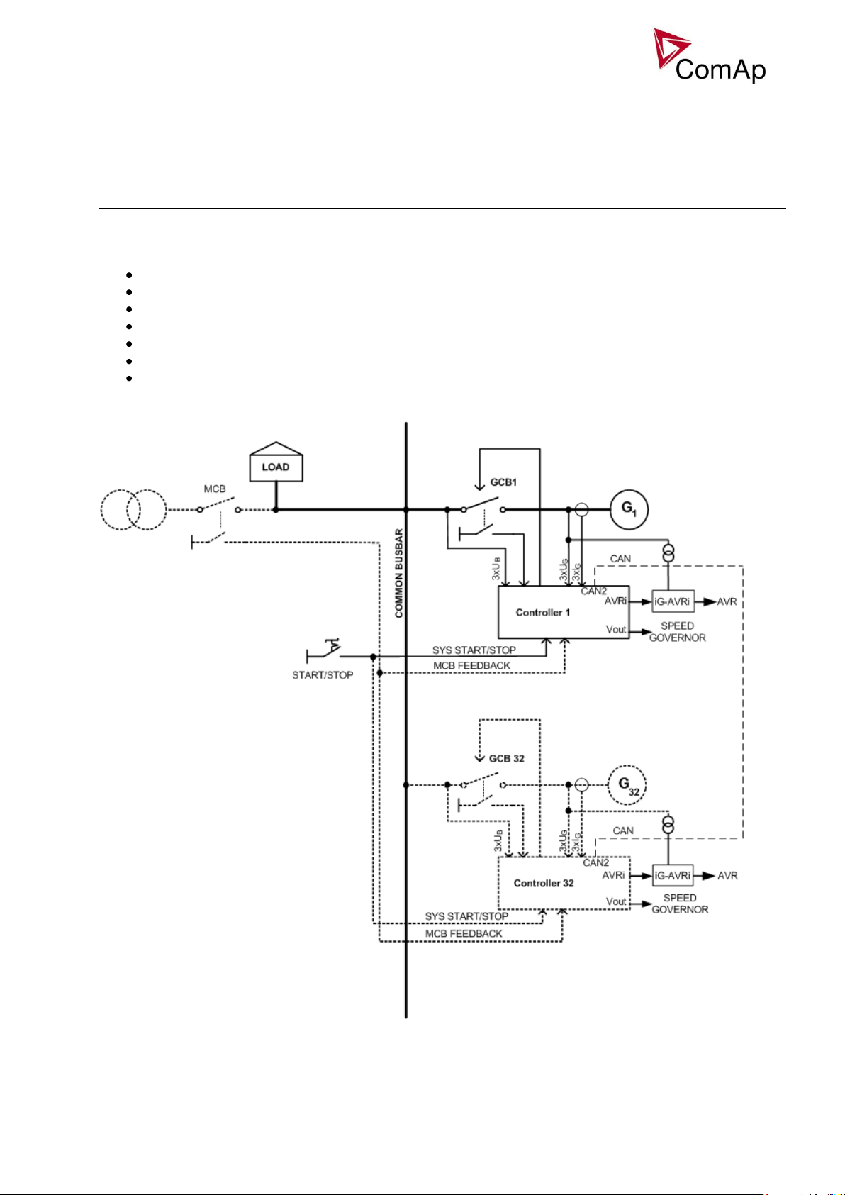
The MINT application is intended for sites where up to 32 gen-sets cooperate with each one. It includes
following main features:
Automatic startup and stop sequences with adjustable timing
Wide range of generator and engine protections, additional freely configurable protections
Multiple island operation with digital active and reactive load sharing
Parallel to the mains operation
One breaker control (GCB) including synchronizing to the busbar.
Soft loading and unloading
Power management - automatic starting and stopping of gen-sets according to the load demand,
running hours equalization and other optimalization features
Inteli NT MINT, SW Version 3.0, ©ComAp –May 2013
IGS-NT-MINT-3.0 Reference Guide.PDF
Page 11

11
Functions
OFF-MAN-AUT mode
OFF mode
Outputs STARTER, GCB CLOSE/OPEN and FUEL SOLENOID are not energized.
Gen-set cannot be started. If START,STOP,GCB ON/OFF buttons are pressed the controller will not
respond.
When the gen-set is running it is not possible to switch directly to OFF mode. First you have to stop the
engine.
MAN mode
1) START - starts the gen-set.
2) GCB ON/OFF
If generator voltage is out of the limits (adjusted in the set point group Gener protect) controller does
not respond to the GCB ON/OFF
a) controller closes GCB to dead bus.
b) controller starts GCB synchronizing when bus voltage is OK and MCB is closed or when other
gen-set(s) provide healthy voltage to the bus. Closes the GCB when synchronized and stays
running in parallel (island or mains parallel).
c) Unloads gen-set and opens the GCB if gen-set was running in parallel to the mains or to other
gen-set(s).
3) STOP
a) When gen-set is running in parallel: transfers the load to the mains or to other gen-set(s), opens
GCB, goes into cooling state and stops the engine.
b) When gen-set is running in single island (or in general there is no mains and no other gen-set(s)
to transfer the load to): opens GCB, goes into cooling state and stops the engine.
c) When engine is running unloaded: activates cooling sequence and then stops the engine.
d) During cooling state causes immediate engine stop.
HINT
The gen-set is permitted to run unloaded for unlimited time.
Controller does not automatically start the gen-set when SYS START/STOP input is closed.
Load control type in mains parallel depends on ProcessControl: #SysLdCtrlPtM = BASELOAD or
LDSHARING setpoint.
SEM
In SEM mode, pressing of START or STOP buttons performs a predefined sequence:
1) START – starts the engine, synchronizes and runs in parallel.
2) STOP – softly unloads the gen-set, opens GCB, provides cooldown and stops the engine.
AUT mode
1) All gen-sets necessary to cover selected LoadRes strt are started when binary input SYS START/STOP
is closed and Pwr management is ENABLED. Power management can be based on kW, kVA or on
relative % reserve.
a) 1 sec delayed when MCB FEEDBACK binary input is closed (mains parallel)
b) delayed #SysAMFstrt del when MCB FEEDBACK binary input is opened – start to island parallel
(multi AMF) situation
2) The first gen-set closes the GCB to the dead bus, the rest are synchronized to the bus.
3) When all necessary gen-sets are connected to the bus and LoadRes strt is achieved, SYST RES OK
output is closed. Output could be used to close the MGCB (Master GCB).
4) Total load and power factor are shared between parallel operating gen-sets.
5) Close input LOAD RESERVE 2 (or 3 or 4) and use setpoint LoadRes strt2(or 3 or 4) to switch to another
load reserve setting. E.g. high load reserve during system start to be able to switch-on big devices, then
during normal operation lower reserve to save engines (and fuel).
Inteli NT MINT, SW Version 3.0, ©ComAp –May 2013
IGS-NT-MINT-3.0 Reference Guide.PDF
Page 12

12
6) If total load increases and selected LoadRes strt is no more fulfilled, after a Next start del next ready
gen-set with the highest priority (lowest priority number) is started and synchronized to the bus.
7) If load decreases and selected LoadRes stp is exceeded, after a Next stop del the running gen-set with
the lowest priority is unloaded, got off line, cooled and stopped.
8) Complete gen-sets group stops when binary input SYS START/STOP opens. If the input MCB
FEEDBACK is closed (gen-sets are in parallel to mains) controllers softly transfer the load to the mains.
When gen-set is unloaded (see GCB open level or GCB open del) opens the output GCB
CLOSE/OPEN.
9) The Running hours balancing or Load demand engines swap can be activated in power management.
HINT
Controller does not respond to GCB ON/OFF , STOP, START buttons and corresponding remote
InteliMonitor or Modbus commands in AUT mode.
Set Basic setting: FltRes GoToMAN = ENABLED to avoid automatic engine start when pressing FAULT
RESET after any 2nd level alarm (Shutdown, Slow stop, Breaker Open&Cooldown).
Active and Reactive Power control modes in MINT
System Base load
Gen-set group is controlled on constant (or adjustable) power. The Baseload value can by changed by
setpoint or via analog input.
Important setpoints: ProcessControl: #SysLdCtrlPtM = BASELOAD; #SysBaseload; SysBaseLdMode.
Local Baseload
Selected gen-set from island or mains parallel running group can be loaded to constant LocalBaseload
value. This engine is taken out from Load sharing and Power management. LocalBaseload value is reduced
only when common group (actual) load is lower than this value. The gen-sets in the group will try to match
their LocalBaseloads (when more than one) based on their controller addresses, so the first limited would be
the one with the highest CAN address. I.e. this function will switch-off automatically in one or more
controllers if there is not enough load to cover all the requested LocalBaseloads.
Important setpoints: ProcessControl: LocalBaseload.
System Base power factor
Gen-set group is controlled in mains parallel to keep a constant (or adjustable) power factor.
Important setpoints: ProcessControl: #SysPFCtrlPtM = BASEPF; #SysPwrFactor.
Import-Export
Gen-set group is controlled to keep constant (or adjustable) Import or Export value. The external controller
InteliMains NT must be connected on the CAN2 to control gen-set group kW I/E.
Important setpoints: ProcessControl: #SysLdCtrlPtM = LDSHARING.
Import/Export power factor
Gen-set group is controlled to keep constant (or adjustable) Import or Export power factor.
Important setpoints: ProcessControl: #SysLdCtrlPtM = VSHARING. The external InteliMains NT controller
must be connected on the CAN2 to control gen-set group PF I/E.
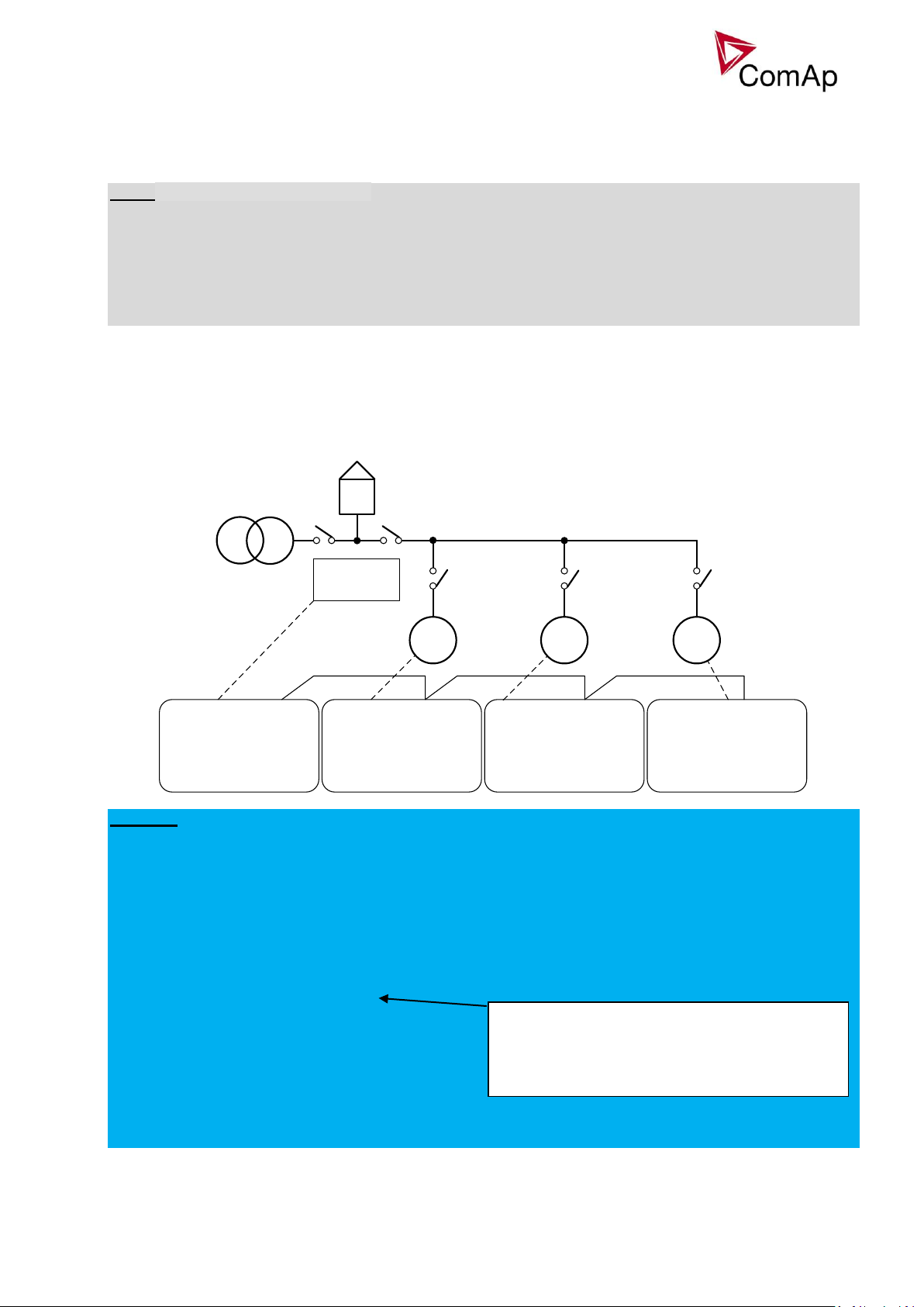
Power management
Automatic gen-set start / stop function based on load changes and/or Running hours or Engine size.
Following functions are available:
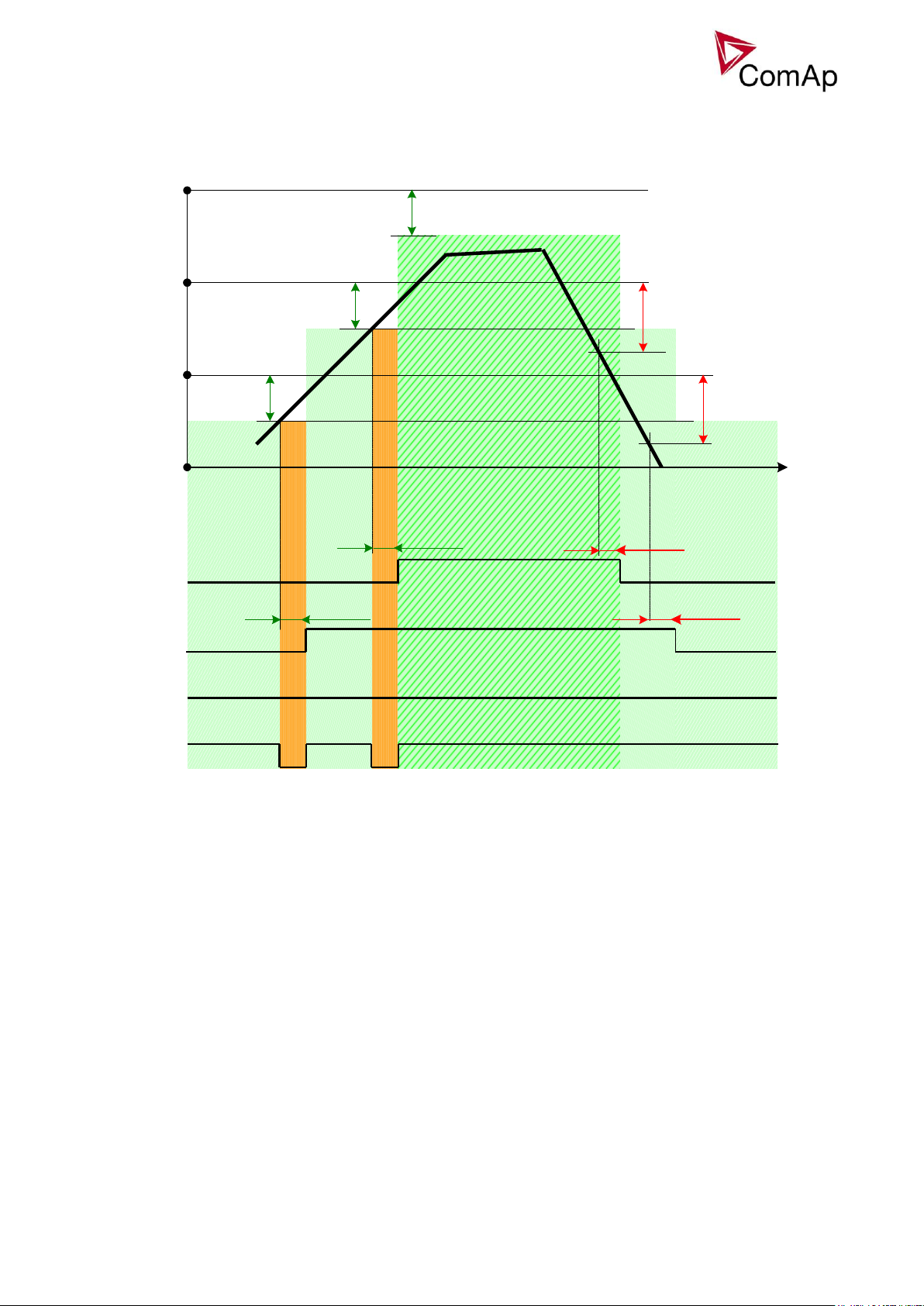
Power management in kW
Guarantees adjustable load reserve (load step) in kW. Suitable for load demand-based optimization.
Activation: Pwr management:#Pwr mgmt mode = ABS (kW)
Inteli NT MINT, SW Version 3.0, ©ComAp –May 2013
IGS-NT-MINT-3.0 Reference Guide.PDF
Page 13
13
Power management in kVA
Gen1
Priority 1
Gen2
Priority 2
Gen3
Priority 3
Gen 1 = Running, Loaded
Gen 2
#LdResStrt1
#LdResStrt1
#NextStrt del
Running
Gen 3
#NextStrt del
Running
#LdResStp1
#NextStp del
Unloading / Cooling
#NextStp del
Unloading / Cooling
#LdResStp1
Actual power [ kW or kVA ]
Time
BO Syst res OK
#LdResStrt1
Figure: Power management function in absolute mode
Guarantees adjustable load reserve (load step) in kVA. Suitable for generator- or busbar dimensioningbased optimization.
Activation: Pwr management:#Pwr mgmt mode = ABS (kVA)
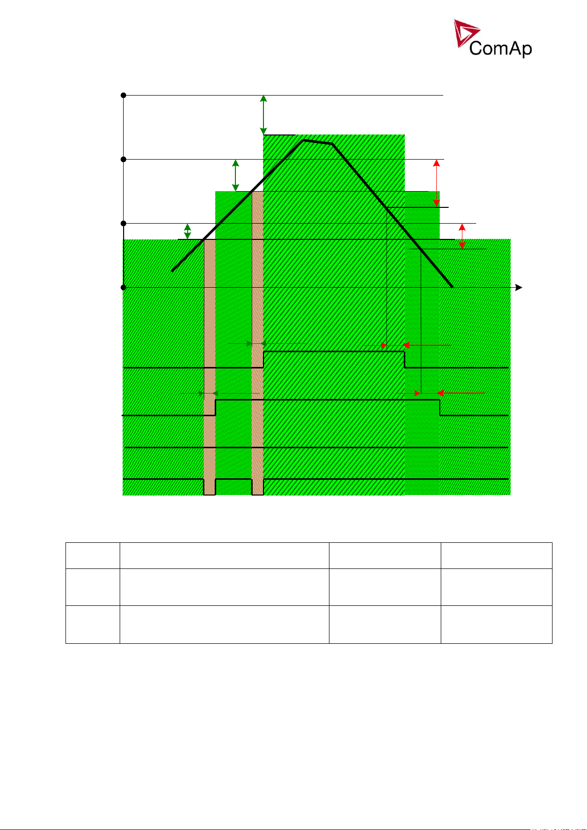
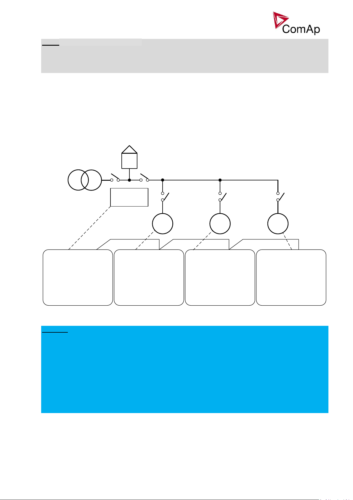
Relative power management in %
Guarantees that the engines are not continuously loaded more than to a certain level. Suitable for engine
life-based optimization.
Activation: Pwr management:#Pwr mgmt mode = REL (%)
Inteli NT MINT, SW Version 3.0, ©ComAp –May 2013
IGS-NT-MINT-3.0 Reference Guide.PDF
Page 14
14
Gen1
Priority 1
Gen2
Priority 2
Gen3
Priority 3
Gen 1 = Running, Loaded
Gen 2
#%LdResStrt1
= 25%
#%LdResStrt1
= 25%
#NextStrt del
Running
Gen 3
#NextStrt del
Running
#%LdResStp1
=37%
#NextStp del
Unloading / Cooling
#NextStp del
Unloading / Cooling
#%LdResStp1
=37%
Actual power [ kW or kVA ]
Time
BO Syst res OK
#%LdResStrt1
= 25%
Reserve
Actual Reserve
Start condition
Stop condition
Absolute
kW / kVA
ARstrt = ΣPg
Nom
– ΣPg
Act
ARstp = ΣPg*
Nom
– ΣPg
Act
ARstrt < #LdResStrt
ARstp > #LdResStp
Relative
%
RRstrt = [(ΣPg
Nom
– ΣPg
Act
) / ΣPg
Nom
].100%
RRstp = [(ΣPg*
Nom
– ΣPg
Act
) / ΣPg*
Nom
].100%
RRstrt < #%LdResStrt
RRstp > #%LdResStp
ARstrt
Actual Absolute reserve in kW or kVA - for engine start calculation.
ARstp
Actual Absolute reserves in kW or kVA - for engine stop calculation.
RRstrt
Actual Relative reserve in % - for engine start calculation.
RRstp
Actual Relative reserves in % - for engine stop calculation.
ΣPg
Nom
Sum of Nominal power of all gen-sets on the bus.
Figure: Power management function in relative mode
art/Stop conditions in Power management
St
Where
Inteli NT MINT, SW Version 3.0, ©ComAp –May 2013
IGS-NT-MINT-3.0 Reference Guide.PDF
Page 15
15
Second lowest considered running hours –
Current lowest considered running hours +
#RunHrsMaxDiff
450 – 250 + 10 = 210 hours
ΣPg*
Nom
Sum of Nominal power of all gen-sets on the bus apart of the one, which is going to be
stopped.
ΣPg
Act
Sum of Actual power of all gen-sets on the bus = system load.
NOTE:
G1 G2 G3
Basic settings:
Contr. Addr = 2
Pwr management:
#PriorAutoSwap = RUN HOURS EQU
Priority ctrl = SLAVE
RunHoursBase = 200h
#RunHrsMaxDiff = 10h
Control group = COMMON
Basic settings:
Contr. Addr = 1
Pwr management:
#PriorAutoSwap = RUN HOURS EQU
Priority ctrl = SLAVE
RunHoursBase = 100h
#RunHrsMaxDiff = 10h
Control group = COMMON
Basic settings:
Contr. Addr = 3
Pwr management:
#PriorAutoSwap = RUN HOURS EQU
Priority ctrl = SLAVE
RunHoursBase = 300h
#RunHrsMaxDiff = 10h
Control group = COMMON
Basic settings:
Contr. Addr = 4
Pwr management:
#PriorAutoSwap = RUN HOURS EQU
Priority ctrl = MASTER
#RunHrsMaxDiff = 10h
Control group = COMMON
InteliMains
CAN
System starting sequences may be very different due to their complexity (i.e. gensets which do not take part
in power management, various nominal powers etc.). Each system should be considered individually.
Optional functions in absolute or relative Power management are:
- Running hours balancing (equalization) – in absolute or relative pwr mgmnt
- Load demand (different size) engines swap – in absolute pwr mgmnt only
- Power management of two or more gen-set groups (bus tie support) – in absolute or relative
pwr mgmnt
Running hours equalization (RHE)
The gen-sets priorities are automatically swapped to balance engine running hours. Up to 32 controllers are
supported.
Activation: Pwr management:#PriorAutoSwap = RUN HOURS EQU
Important setpoints: RunHoursBase, #RunHrsMaxDiff, Priority ctrl, Control group
Figure: Running Hours Equalization example
EXAMPLE:
In this example the system is shown in previous figure. InteliMains assumes the role of master in priority
swapping and swappes priority of the engines based on their running hours.
Gen-set 1 running hours = 250 -> running hours considered in RHE = 150 (250-RunHoursBase)
Gen-set 2 running hours = 450 -> running hours considered in RHE = 250 (450-RunHoursBase)
Gen-set 3 running hours = 750 -> running hours considered in RHE = 450 (750-RunHoursBase)
All the engines have the same nominal power which is 700 kW. Originally priority of gen-sets was G1 = 3, G2
= 2, G3 = 1. Load demand in this example is constant and it is 500 kW (so only one engine is running at any
time).
InteliMains will change priority of gen-set 1 to 1 because it has the lowest considered running hours and genset 1 will run for 210 hours.
After 210 hours, situation will change. Gen-set 2 will
now have the lowest considered running hours
(Gen-set 1 = 460, Gen-set 2 = 450, Gen-set 3 =
750). Gen-set 2 will now have priority 1 and it will run
for 20 hours. Then Gen-set 1 will run again for 20
hours. This will continue until both engines will have
running hours 770. Then the third engine will run. At that point engines will be swapping with period of 20
hours (2 x Pwr management:#RunHrsMaxDiff).
Inteli NT MINT, SW Version 3.0, ©ComAp –May 2013
IGS-NT-MINT-3.0 Reference Guide.PDF
Page 16
16
G1 G2 G3
Basic settings:
Contr. Addr = 2
Pwr management:
#PriorAutoSwap = LD DEMAND SWAP
Priority ctrl = SLAVE
#PwrBandContr1 = 1
#PwrBandContr2 = 2
#PwrBandContr3 = 2+3
#PwrBandChngDlUp = 10s
#PwrBandChngDlDn = 10s
Control group = COMMON
Basic settings:
Contr. Addr = 1
Pwr management:
#PriorAutoSwap = LD DEMAND SWAP
Priority ctrl = SLAVE
#PwrBandContr1 = 1
#PwrBandContr2 = 2
#PwrBandContr3 = 2+3
#PwrBandChngDlUp = 10s
#PwrBandChngDlDn = 10s
Control group = COMMON
Basic settings:
Contr. Addr = 3
Pwr management:
#PriorAutoSwap = LD DEMAND SWAP
Priority ctrl = SLAVE
#PwrBandContr1 = 1
#PwrBandContr2 = 2
#PwrBandContr3 = 2+3
#PwrBandChngDlUp = 10s
#PwrBandChngDlDn = 10s
Control group = COMMON
Basic settings:
Contr. Addr = 4
Pwr management:
#PriorAutoSwap = LD DEMAND SWAP
Priority ctrl = MASTER
#PwrBandContr1 = 1
#PwrBandContr2 = 2
#PwrBandContr3 = 2+3
#PwrBandChngDlUp = 10s
#PwrBandChngDlDn = 10s
Control group = COMMON
InteliMains
CAN
NOTE:
Core power management is still fully functional.
Priority setpoints are not actually changed. Virtual values are used. If changing of priority setpoints is
required, they need to be changed and RHE needs to disabled and enabled again for the changes to take
place
Different sized engines (Load demand) swap (LDS)
Up to three running engines (priorities) can be swapped based on load demand (e.g. one “small” engine may
run on “small” load and swaps to another one, “big” engine that runs when load increases). This function is
availatible only in combination with absolute power management.
Activation: Pwr management:#PriorAutoSwap = LD DEMAND SWAP
Important setpoints: #PwrBandContr1, #PwrBandContr2, #PwrBandContr3, #PwrBandContr4,
#PwrBandChngDlUp, #PwrBandChngDlDn, Load reserve setpoints (depending on selected load reserve
set), Priority ctrl, Control group.
EXAMPLE:
In this example the system is shown in previous figure. InteliMains assumes the role of master in priority
swapping and swappes priority of the engines based on user defined power bands. In power band 1, gen-set
with CAN address 1 will be running, in power band 2, gen-set with CAN address 2 will be running and in
power band 3, gen-sets with address 2 and 3 will be running.
Power bands are changed up if:
or down if:
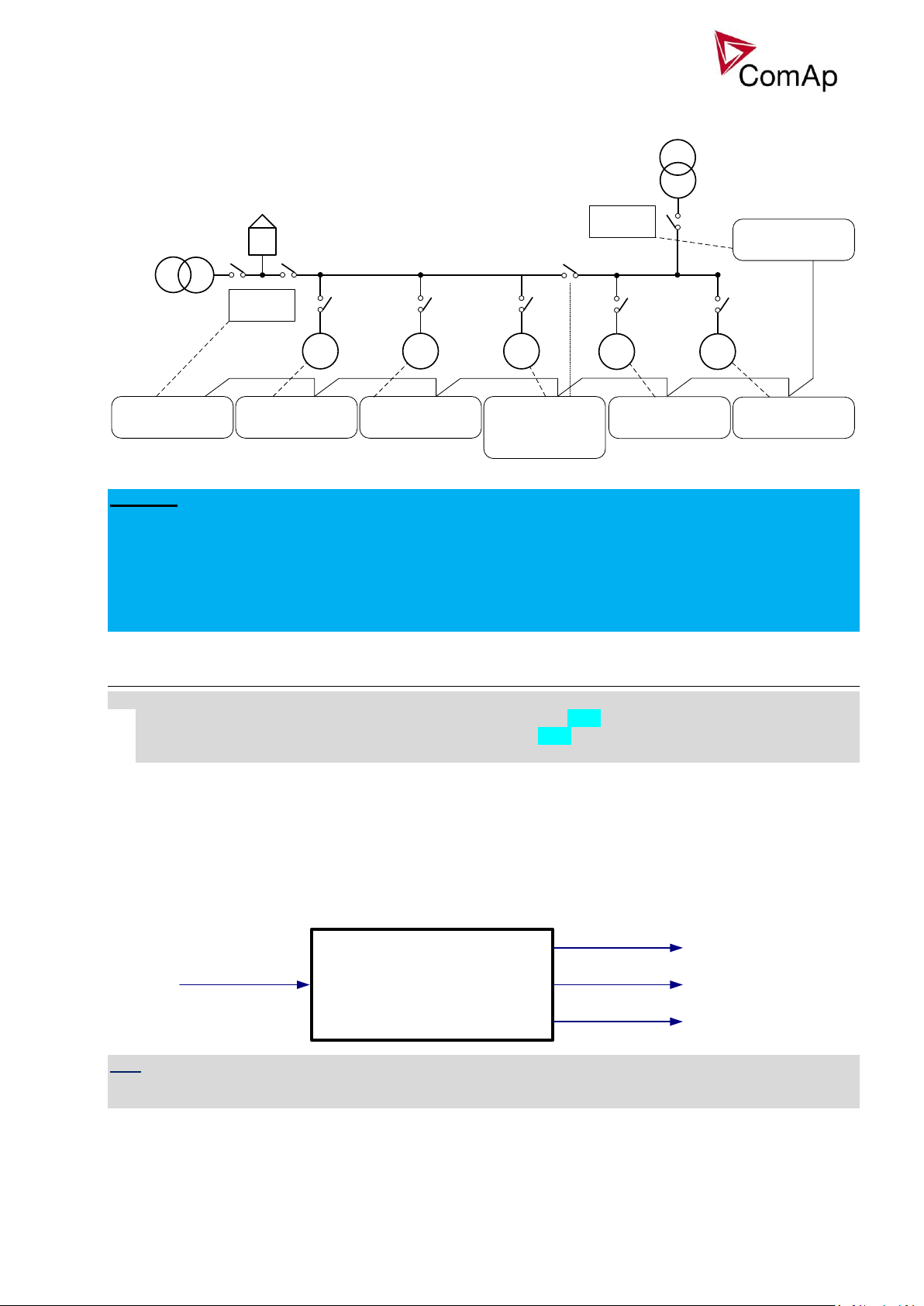
Power management using control groups
When a Bus-tie separates the gen-set groups, they can operate separately (power management, load
control, mode of function etc.). When GROUPLINK is active, all the gen-sets in according groups are controlled
by InteliMains with lower CAN address only.
Inteli NT MINT, SW Version 3.0, ©ComAp –May 2013
IGS-NT-MINT-3.0 Reference Guide.PDF
Figure: Load Demand Swapping example
(Nominal power of all gen-sets in a particular band - Total generated power by gen-sets in power
management) < Reserve for start
(Nominal power of all gen-sets in next lower band - Total generated power by gen-sets in power
management) > Reserve for stop
Page 17
17
G1 G2 G3
Basic settings:
Contr. Addr = 2
Pwr management:
Control group = COMMON
Basic settings:
Contr. Addr = 1
Pwr management:
Control group = COMMON
Basic settings:
Contr. Addr = 3
Pwr management:
Control group = COMMON
GroupLinkLeft = COMMON
GroupLinkRight = 2
BTBfeedback = GroupLink
Basic settings:
Contr. Addr = 6
Pwr management:
Control group = COMMON
InteliMains
CAN
G4 G5
InteliMains
Basic settings:
Contr. Addr = 4
Pwr management:
Control group = 2
Basic settings:
Contr. Addr = 5
Pwr management:
Control group = 2
Basic settings:
Contr. Addr = 7
Pwr management:
Control group = 2
Load shedding: Ld shed level
Ld shed delay
Ld recon level
Ld recon delay
AutoLd recon
LdShed stage 1
LdShed stage 2
LdShed stage 3
ManualLdRecon
Important setpoints: Control group, GroupLinkLeft, GroupLinkRight
Figure: Power management using control groups
EXAMPLE:
In the example above, bus tie breaker separates gen-sets into two groups. BTB is operated manually in this
example. If BTB is opened, each control group is working independently. If the BTB closes, controller
number 3 sends signal via CAN bus and groups COMMON and 2 are connected together. One InteliMains
(the one with lower CAN address) takes over and controls both groups. It is not possible to use both
InteliMains parallel to the Mains when BTB is closed and InteliMains with lower CAN address takes over the
control. In this case gen-sets are controlled only by this InteliMains and the second InteliMains does not have
any means to control its parallel function.
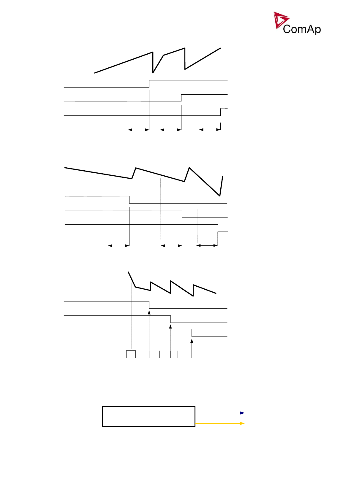
Load shedding
All LOAD SHED outputs are activated (closed) to trip the unessential load when gen-set goes to island:
a) When GCB is closed after mains fail and gen-set starts in SEM / AUT mode.
b) When MCB opens from parallel to mains operation in SEM / AUT mode.
c) Before MCB is opened in MAN mode by button.
The load shedding function is active in all controller modes except OFF.
Load shedding has three steps and each step is linked with its own Load shed x binary output. There is only
one load shed level and delay for all three steps as well as recon level and delay. Load shed can only move
from one step to the next, e.g. No LoadShed to LdShed S1 to LdShed S2 to LdShed S3 and vice versa.
If manual reconnection of the load is desired, the AutoLd recon setpoint needs to be disabled (AutoLd recon
= DISABLED) and the MAN load recon binary input needs to be configured.
Rising edge on this input resets the controller to a lower stage, but only if the load is under the Ld recon level
at that moment.
HINT
If no Load Shedding outputs are configured, there is no record to history and no scrren timer indication of the
activity of this function.
Inteli NT MINT, SW Version 3.0, ©ComAp –May 2013
IGS-NT-MINT-3.0 Reference Guide.PDF
Page 18
18
Ld shed del
Ld shed del
Ld shed del
BO Load shed 1
BO Load shed 2
BO Load shed 3
Ld shed level
Gen-set power
closed
closed
closed
Ld recon del Ld recon delLd recon del
BO Load shed 2
Ld recon level
Gen-set power
BO Load shed 3
BO Load shed 1
opened
opened
opened
BO Load shed 2
Ld recon level
G
e
n
-
s
e
t
p
o
w
e
r
BO Load shed 3
BO Load shed 1
BI Man load recon
opened
opened
opened
no action
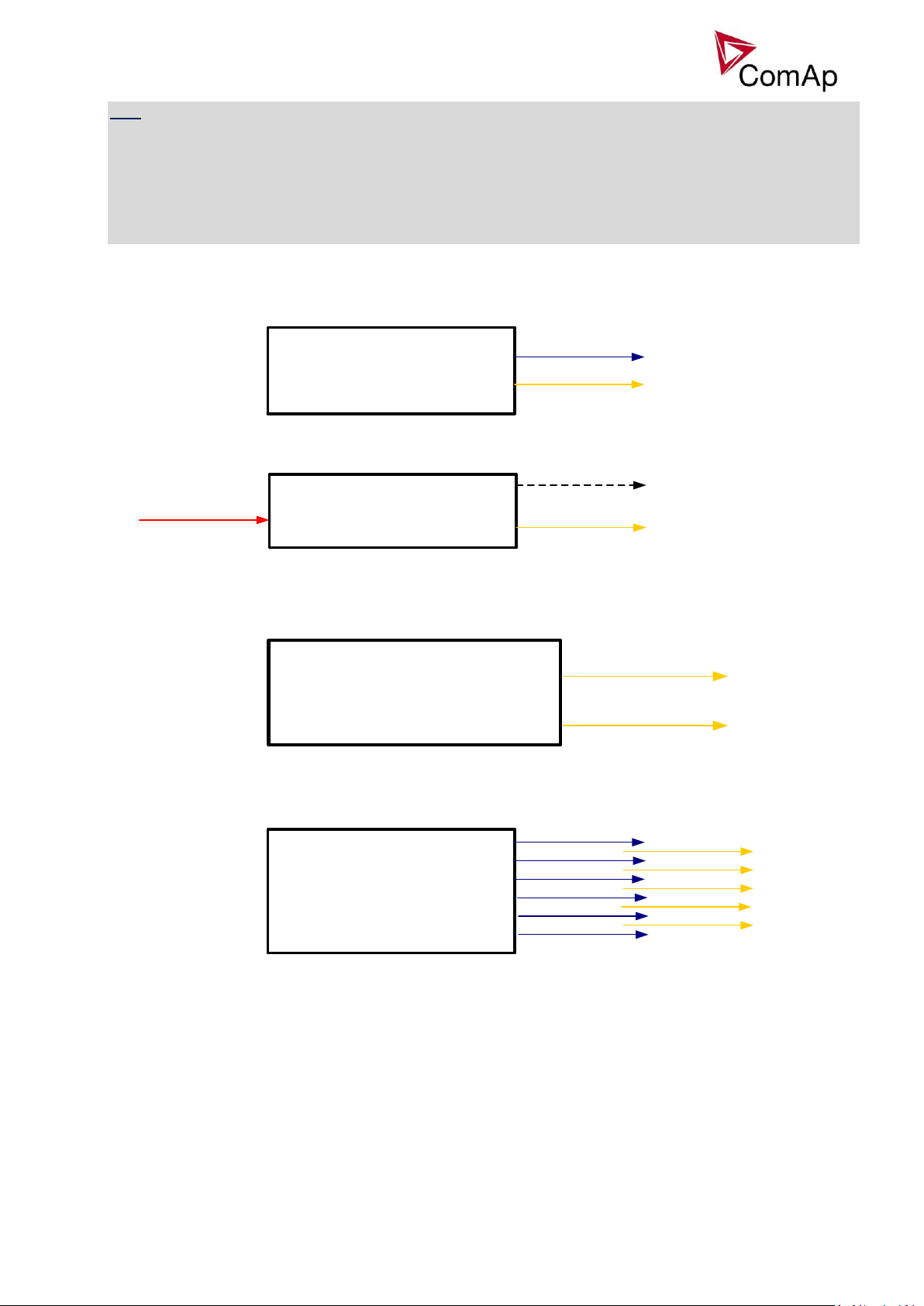
Engine params: PrelubrTime
PrelubrPause
Prelubr pump
Not lubricated
Load reconnection – automatic -> AutoLd recon = ENABLED
Load reconnection – manual -> AutoLd recon = DISABLED
Engine states
Engine prelubrication
Inteli NT MINT, SW Version 3.0, ©ComAp –May 2013
IGS-NT-MINT-3.0 Reference Guide.PDF
Page 19
19
Engine params: Cooling speed
Cooling time
Cooldown optim
AfterCoolTime
Cooling pump
Cooling
Engine params: Warming load
Warming temp
Max warm time
Reduces
requested load
Warming
Warming temp
Analog input
Engine protect: Service time 1
Service time 2
Service time 3
Service time 4
WrnServiceT3+4
WrnServiceT1+2
Engine params: Starting RPM
Prestart time
MaxCrank time
CrnkFail pause
Crank attempts
Idle time
Fuel solenoid
Starting
Stop solenoid
Starter
Prestart
Cranking
Crank procedure
Idle/Nominal
Idle run
Ignition
Operational
HINT
To use Prelubrication, configure Binary output PRELUBR PUMP first.
Prelubrication is disabled in controller OFF mode or if Prelubr time is set to zero.
Binary output PRELUBR PUMP is opened when engine is running.
Prelubrication cycle starts with PrelubrPause after engine stop.
Prelubrication cycle starts immediately when controller power supply is switched on or when mode changes
from OFF to MAN or AUT or after Emergency stop was reset. An Alarmlist message “Not lubricated” is active
until this first lubrication cycle has been completed.
Engine cooling
Engine warming
Service time alarm
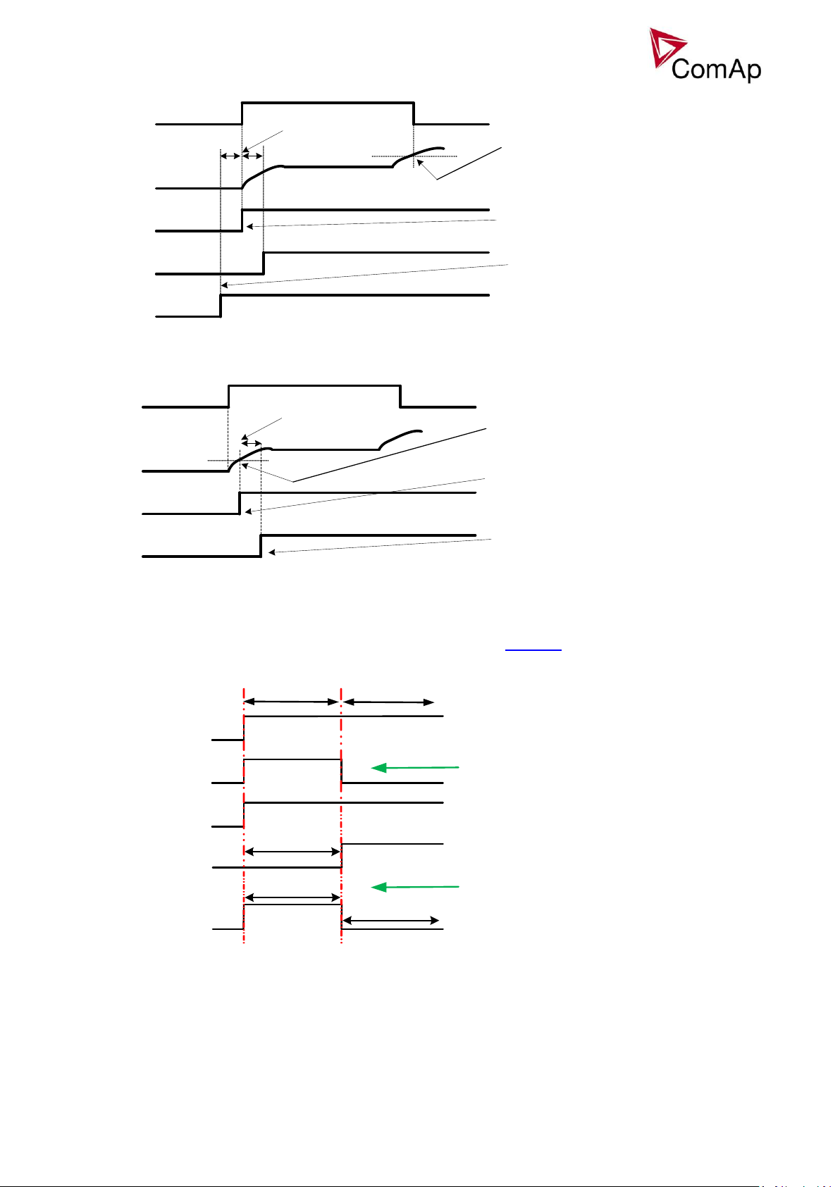
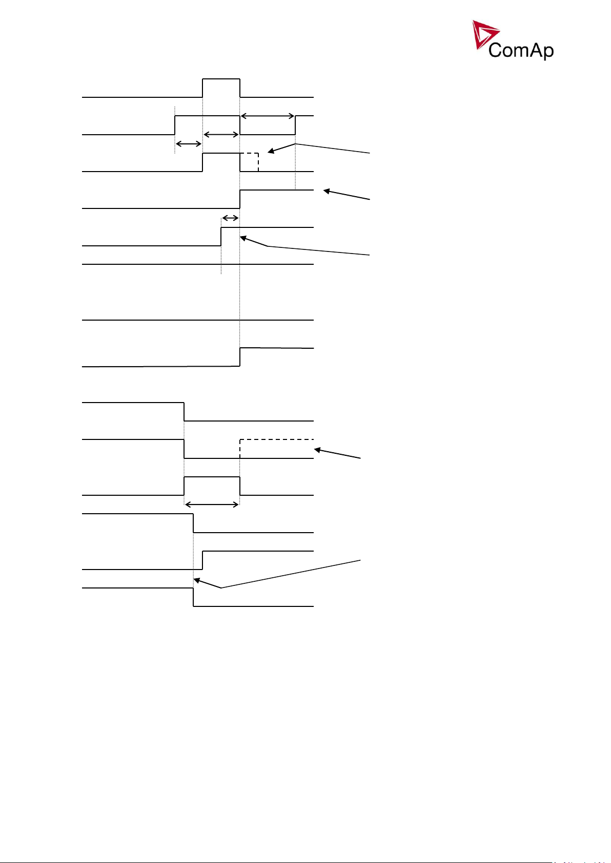
Engine starting procedures
Engine starting procedure if Engine params: Fuel solenoid = DIESEL ENGINE with different setting of
FuelSol offset.
Inteli NT MINT, SW Version 3.0, ©ComAp –May 2013
IGS-NT-MINT-3.0 Reference Guide.PDF
Page 20
20
-5s
BO: Fuel solenoid
RPM
BO: Starter
Negative values possible only
with DIESEL setting.
BO: Fuel solenoid
BO: Fuel solenoid
0 s offset means that Fuel
solenoid is activated together
with Starter.
FuelSol offset
+5s
RPM > Starting RPM or
Oil pressure > Starting POil or
RunIndication1,2,3 = 1
BO: Fuel solenoid
BO: Fuel solenoid
RPM > 30
BO: Starter
0 s FuelSol offset
activates
the Fuel solenoid
immediately if RPM > 30.
FuelSol ofset countdown is
started if RPM > 30.
Max up to 5s
Fuel solenoid activation
FuelSol offset
+5s
= 231 V
Idle run
BI: Sys Start /stop
BO: Starter
BO: Fuel solenoid
RPM
GenNomV
< Starting RPM
= 1000 V
Cranking
GenNomV is forced during
BO: Starter is deactivated
Starting RPM > 1000
cranking untill
Engine starting procedure if Engine params: Fuel solenoid = GAS ENGINE
Engine starting procedure with own starting procedure:
Engine is started after Starting RPM reach starting leve or other condition. BO: Starter is deactivated only if
one of those condition is fulfilled.
Generator nominal voltage is 231V but during Cranking is forced to 1000V until engine in Idle state (at least
one of condition has to be fulfilled).
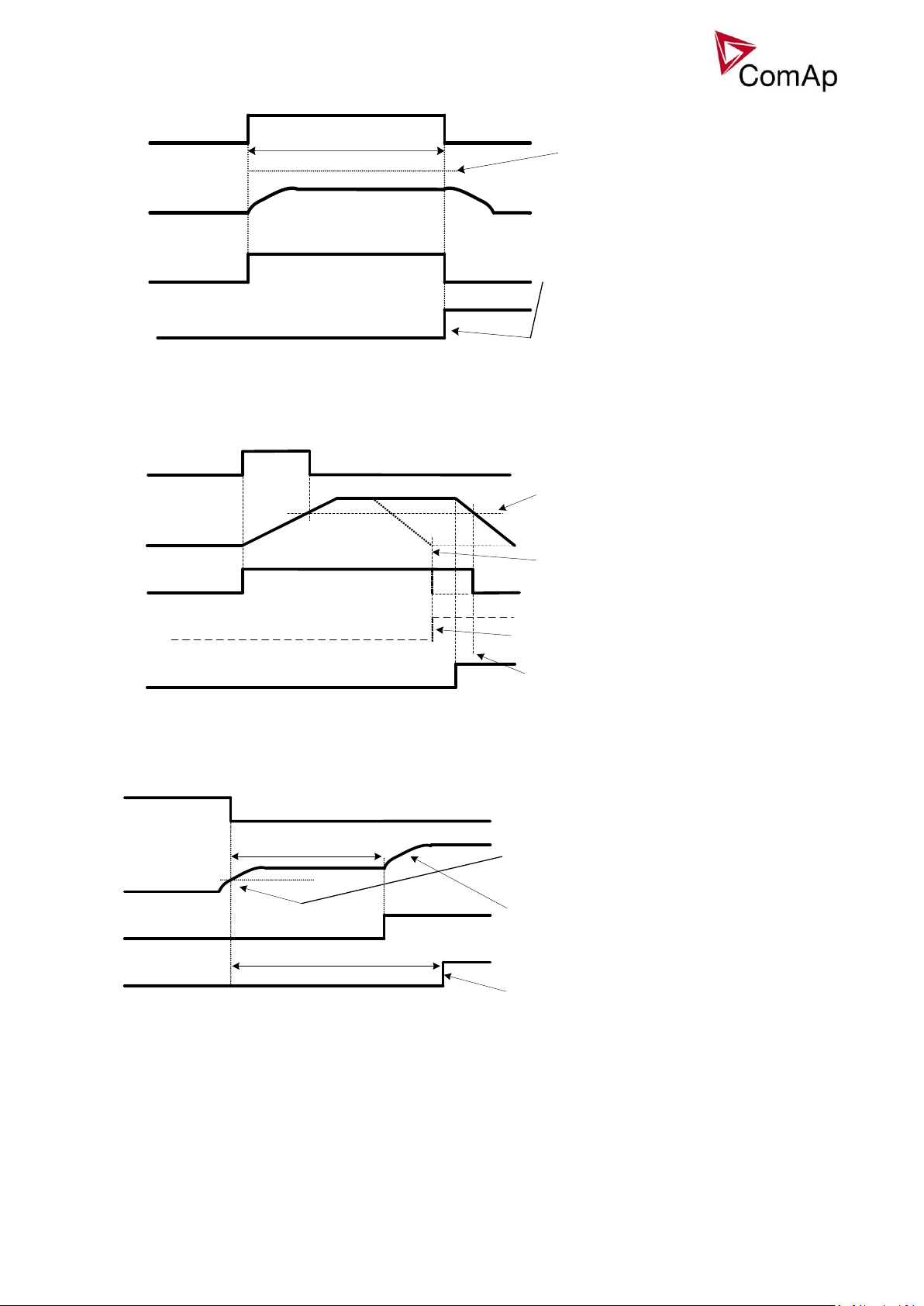
Unsuccessful start – no Engine params: Starting RPM reached
Inteli NT MINT, SW Version 3.0, ©ComAp –May 2013
IGS-NT-MINT-3.0 Reference Guide.PDF
Page 21
21
MaxCrank time
BO: Fuel solenoid
RPM
BO: Starter
Start fail activated only if this
has been the last start attempt in
a series.
BO: Start fail
Starting RPM level not reached
and no other signs of running
engine is present.
RPM dropped under Starting RPM
level and Underspeed enabled
-> protection activated.
Underspeed unblocking
BO: Fuel solenoid
RPM
BO: Starter
Start fail activated because of
RPM loss.
BO: Start fail
Starting RPM level.
Underspeed protection is not yet
Active. Underspeed is detected
only if RPM <= 2 and other
signs of moving engine
present = „still engine“.
= 5s
BO: Idle/Nominal
RPM
BO: Starter
Transition Idle - > Nominal RPM.
Idle time <5s
Starter switched off after
reaching Starting RPM or other
engine „running“ condition.
Underspeed protection
unblocked
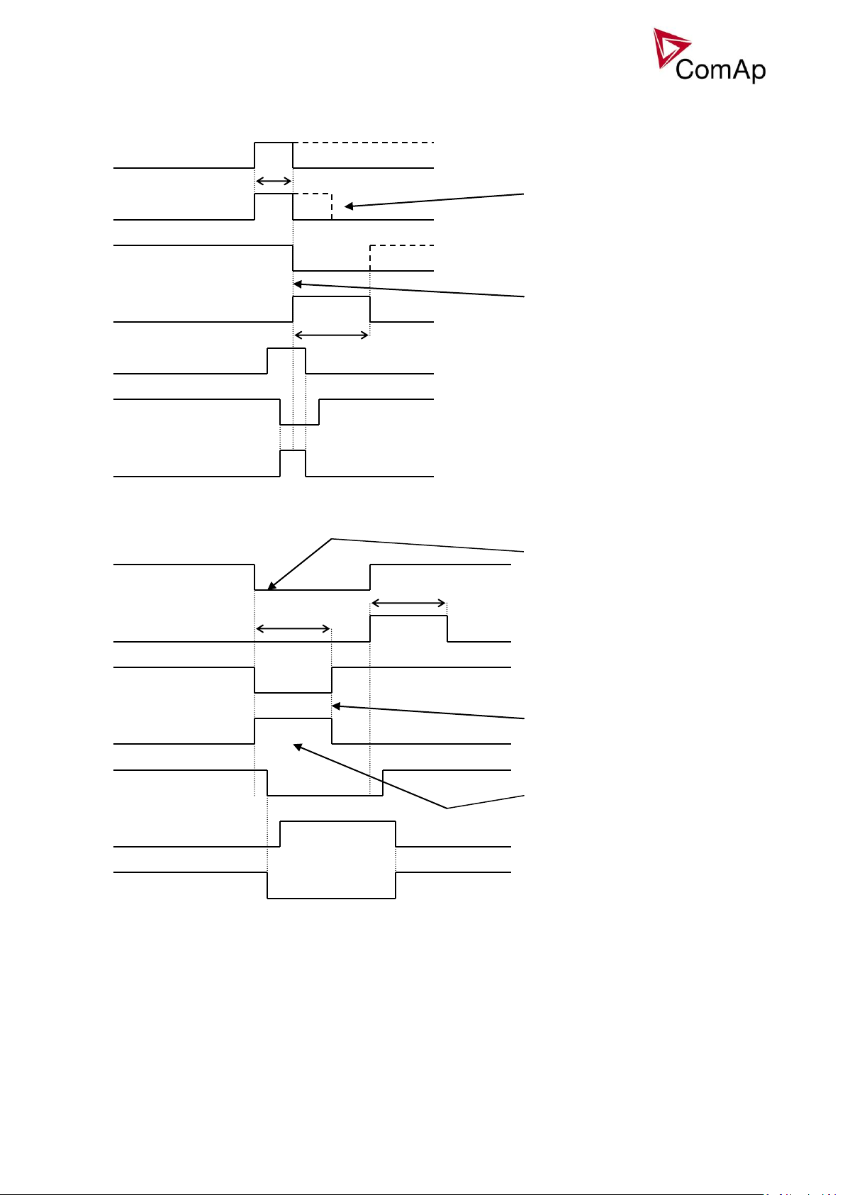
Unsuccessful start – RPM disappeared before/after Underspeed protection got active:
Underspeed protection unblocking if Idle time < 5s:
Underspeed protection unblocking if Idle time > 5s:
Inteli NT MINT, SW Version 3.0, ©ComAp –May 2013
IGS-NT-MINT-3.0 Reference Guide.PDF
Page 22
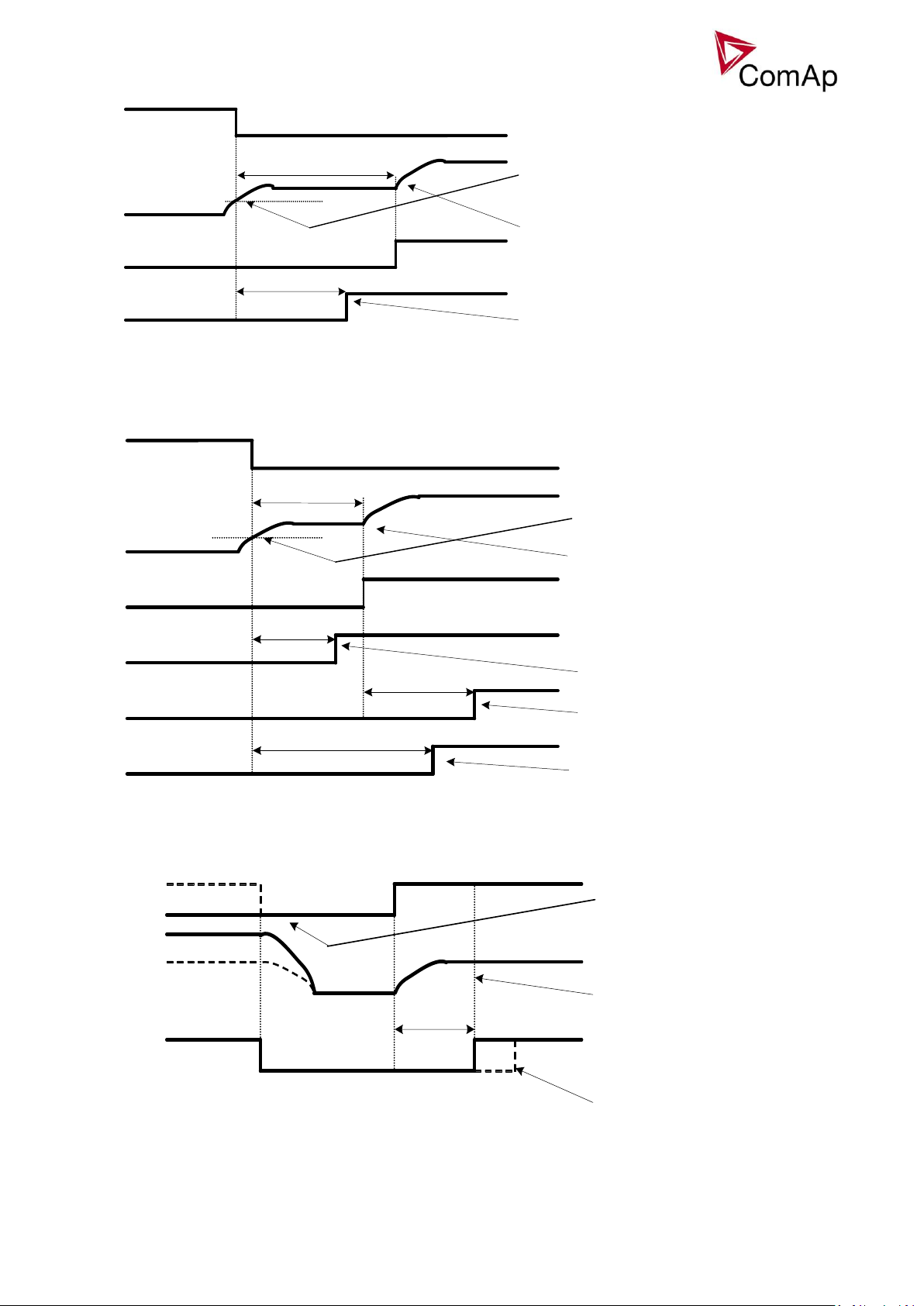
22
Idle time > 5s
= 5s
BO: Idle/Nominal
RPM
BO: Starter
Transition Idle - > Nominal RPM.
Starter switched off after
reaching Starting RPM or other
„running“ condition.
Underspeed protection
unblocked.
= 5s
Max stab time
ProtDel GroupX
Idle time
BO: Idle/Nominal
RPM
BO: Starter
Transition Idle - > Nominal RPM.
Starter switched off.
Underspeed protection
unblocked.
Electrical protections enabled.
„Engine running only“
protections of group X (=1 -3)
enabled.
Underspeed unblocking
PreVentil time
BO: Fuel solenoid
RPM
BO: Starter
Last unsuccessful start attempt or
engine Shutdown.
Starter activated, but Fuel solenoid
delayed for PreVentil time because:
last start attempt wasn‘t successful or
engine Shutdown or
this is the first start attempt after the
controller switch -on.
Additional Fuel solenoid activation
delay can be caused by
FuelSol offset setting.
Transition Idle -> Nominal RPM, protections unblocking:
Preventilation (if Fuel solenoid = GAS):
Inteli NT MINT, SW Version 3.0, ©ComAp –May 2013
IGS-NT-MINT-3.0 Reference Guide.PDF
Page 23
23
+25%
= MaxCrank time
BO: Fuel solenoid
RPM
BO: Starter
( CrankAttempts - 1) the attempt
The last crank attempt is extended by
25% of MaxCrank time, with Fuel
solenoid closed, to ventilate the gas
from the engine.
Fuel solenoid activation delay can
be set using FuelSol offset.
1s
BO: Stop pulse
BO: Stop solenoid
Stop time
BO: Fuel solenoid
RPM + pick - up signal
Typical engine stop time
Correct setting – Stop time
setpoint is set to longer
time than typical engine
stop time.
pick up signal
BO: Stop pulse
BO: Stop solenoid
Stop time
BO: Fuel solenoid
actual RPM
Moment of the pick -up
sensor fault – measured
RPM=0.
In this moment „still engine“
is detected. If pick-up sensor
failed, there may be other
signals determining if
engine is still moving or not.
1s
Ventilation (if Fuel solenoid = GAS ENGINE):
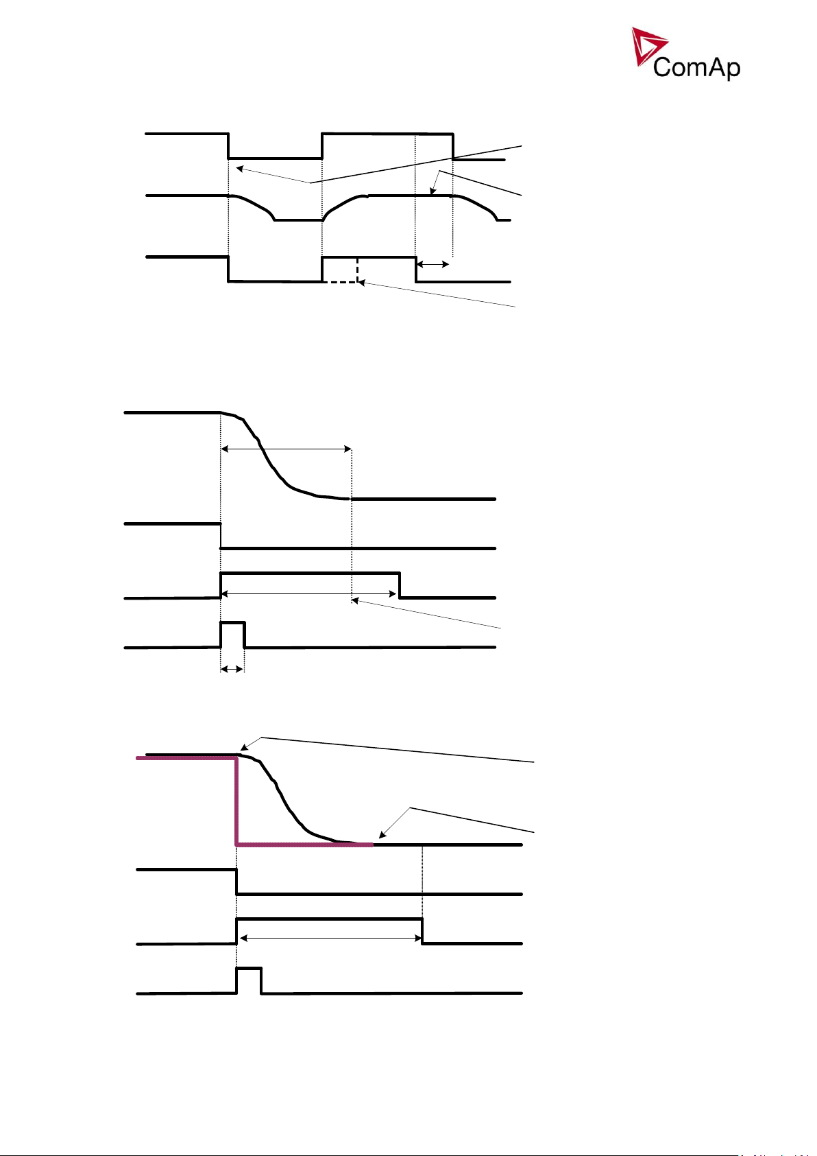
Engine stopping procedures
Normal engine stop:
Pick-up sensor fault – forced engine stop:
Normal engine stop, but Stop time is set too short:
Inteli NT MINT, SW Version 3.0, ©ComAp –May 2013
IGS-NT-MINT-3.0 Reference Guide.PDF
Page 24
24
2s
5s
BO: Stop solenoid
Stop time
BO: Fuel solenoid
RPM + pick - up signal
Stop command issued.
In this moment „still engine“
is detected.
In this moment the Stop time
elapsed, but the engine is still
moving. „Sd Stop fail“ alarm
appears.
„Still engine“ confirmed.
Additional 5s delay elapsed,
Stop solenoid deactivated.
BO: Stop pulse
5s
BO: Stop solenoid
Stop time
BO: Fuel solenoid
RPM + pick - up signal > 0
Stop command issued, but
no reaction.
The cyclic stop attempts
continue until the engine
actually stops.
Stop time
In this moment the Stop time
elapsed, but the engine is still
moving. „Sd Stop fail“ alarm
appears.
The fuel or stop valve probably
stucked in wrong position.
BO: Stop pulse
BO: Stop solenoid
= Stop time
BO: Fuel solenoid
measured RPM = 0
Stop button pressed (MAN
mode).
Stop solenoid activated for
Stop time period.
Stop pulse activated for 1s.
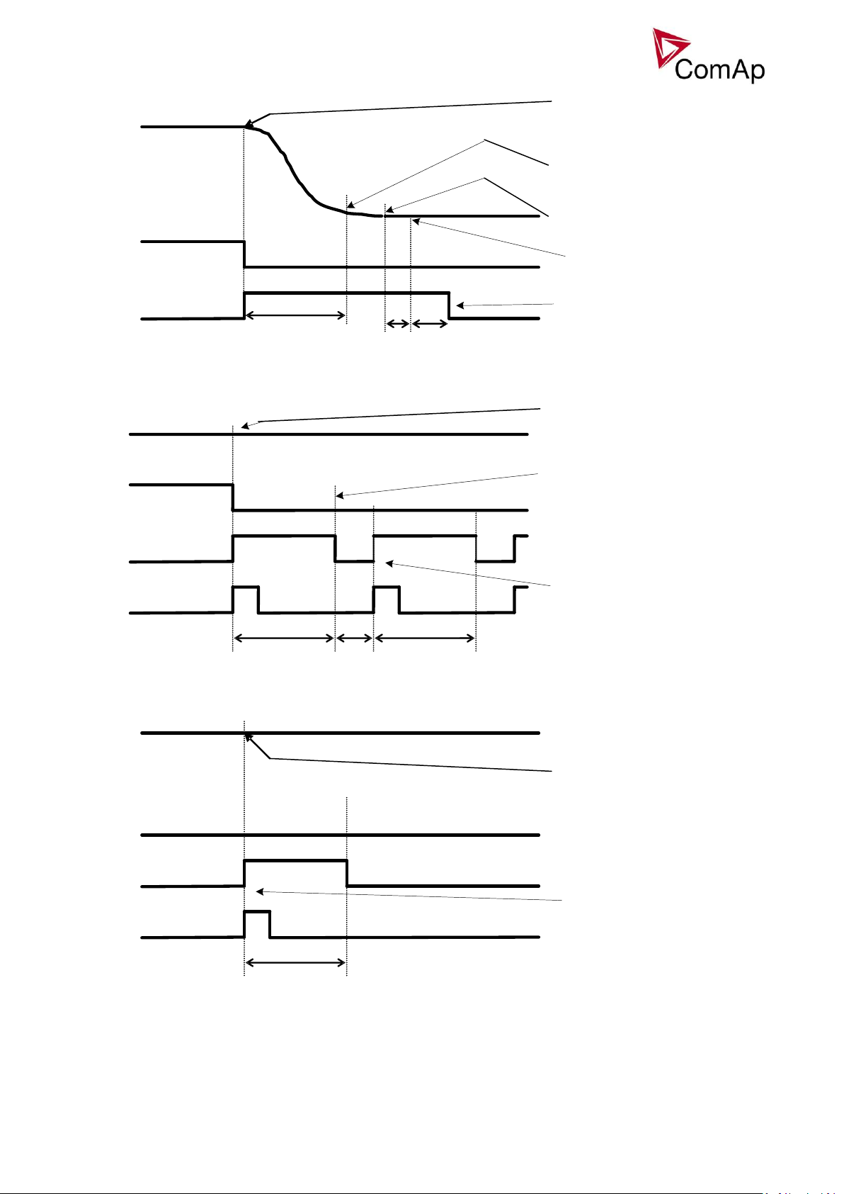
Unsuccessful engine stop:
“Forced” stop in still state:
Spontaneous engine start-up:
Inteli NT MINT, SW Version 3.0, ©ComAp –May 2013
IGS-NT-MINT-3.0 Reference Guide.PDF
Page 25
25
B) BO: Stop solenoid
=2+10s
A) BO: Stop solenoid
Stop time
BO: Fuel solenoid
measured RPM
„Engine running“ condition
detected. Alarm „Sd Stop fail“
appears.
„Still engine“ condition
achieved.
Stop time
A) Stop time long enough to
stop the engine.
B) Stop time too short,
additional Stop solenoid
activation needed.
The overlay is 2+10s since „still
engine“ condition achieved.
Gen V > 25% Generator Nominal
D+ terminal active for minimum 1s
Idle run
> Starting RPM
> 25% GenNomV
Cranking
Oil press > Starting POil
AI: Oil press function
Voltage (any phase)
RPM > Starting RPM
RunIndication 1,2,3 active
Oil Press
D+ indication
RPM
GenNomV
BI: RunIndication 1,2,3
BO: Fuel solenoid
or
or
or
or
Starting
“Engine started” conditions
- Engine speed (RPM) > Starting RPM or
- AI: Oil press > Starting POil or
- D+ terminal active for minimum 1s or
- BI: RunIndication 1 or 2 or 3 = active or
- Generator voltage > 25% of GenNomV (any phase)
-
“Engine running” conditions
- RPM > Engine params: Starting RPM or
- Analog input Oil pressure > Engine params: Starting POil or
Inteli NT MINT, SW Version 3.0, ©ComAp –May 2013
IGS-NT-MINT-3.0 Reference Guide.PDF
- D+ terminal active and Engine params: D+ function = ENABLED or
- Active Binary input RunIndication1 or
Page 26

26
- Active Binary input RunIndication2 or
- Active Binary input RunIndication3 or
- Vgen > 15 V (any phase).
“Still engine” conditions
- Engine speed (RPM) = 0 and
- AI: Oil press < Starting POil and
- D+ terminal not active and
- BI: RunIndication 1 and 2 and 3 = not active and
- Generator voltage < 15V (all phases) and
- Generator frequency = 0 Hz and
- if all above conditions are fulfilled, additional 2s delay is necessary to confirm “still engine”
NOTE:
If any of the functions not used (e.g. BI RunIndication3 not configured), it’s state is omitted in the evaluation.
This is not valid for RPM comparisons, this condition is always active.
Circuit breakers operation sequence, GCB/MCB fail detection
NOTE:
In the following text, “CB” abbreviation is used for MCB or GCB respectively.
Related binary inputs:
- CB fdb – CB feedback binary input
- CB fdb neg – negative CB feedback binary input. Used for increasing the reliability of CB status
evaluated by the controller. In case that it is not configured, negative value of CB fdb is calculated
internally within the controller.
Related binary outputs:
- CB close/open – output for circuit breaker. Equals to 1 during the time when CB is requested o be
closed.
- CB ON coil – output for closing coil of the CB. 2s pulse (5s if synchronising is not provided by the
particuilar CB) is used for closing the CB.
- CB OFF coil – output for opening coil of the CB. 2s pulse (5s if synchronising is not provided by the
particuilar CB) is used for opening the CB.
- CB UV coil – output for undervoltage coil of the CB. Permanently active, 2s negative pulse (5s if
synchronising is not provided by the particuilar CB) is used for CB opening request
- CB status – output indicating CB status as evaluated by the controller. This signal is used for lighting
LEDs on the panel, switching the regulations, CB fail evaluation, etc.
Inteli NT MINT, SW Version 3.0, ©ComAp –May 2013
IGS-NT-MINT-3.0 Reference Guide.PDF
Page 27

27
Possible CB sequences:
2s
BO: CB status
BI: CB fdb neg
BI: CB fdb
BO: CB ON coil
1s
BO: CB close/open
BO: CB UV coil
minimum 1s from UV switching on,
together with MinStab time elapsing is
necessary before the CB is allowed to
close
When closing the CB, the CB status LBO
switches over only when both feedbacks
are in correct position
CB close command:
Inteli NT MINT, SW Version 3.0, ©ComAp –May 2013
IGS-NT-MINT-3.0 Reference Guide.PDF
Page 28
28
2s
2s
1s
BO: CB OFF coil
2s
BO: CB status
BI: CB fdb neg
BI: CB fdb
BO: CB ON coil
1s
BO: CB close/open
BO: CB UV coil
If the CB is not closed after
the first attempt, it is only reset
by OFF pulse and no CB fail is
issued. This would be issued
after the second unsuccessfull
attempt.
BO: CB status = 0
BI: CB fdb neg = 1
BI: CB fdb = 0
BO: CB fail
ON pulse has finished and CB
status is not =1. CB fail is
issued immediatelly
Repeated CB close command:
Inteli NT MINT, SW Version 3.0, ©ComAp –May 2013
IGS-NT-MINT-3.0 Reference Guide.PDF
Page 29
29
2s
BO: CB OFF coil
BO: CB fail
500 ms
<2s
BO: CB status = 0
BI: CB fdb neg = 1
BI: CB fdb
BO: CB ON coil
1s
BO: CB close/open
BO: CB UV coil
CB fail – If any inconsistence between
the two feedback signals is detected, CB
fail is issued.
ON pulse is shortened/interrupted
and replaced by UV and OFF pulse
OFF pulse is activated until both
feedbacks return to the correct
position +2 seconds.
2s
BO: CB OFF coil
BI: CB fdb neg
BI: CB fdb
BO: CB close/open
BO: CB UV coil
During CB opening the CB status
LBO is deactivated with change of
the first feddback status
Further behavior of UV output
depends on the system status. In
case of transition to cooling stays
off, if the Cb was opened manually
and the engine keeps running, it
activates again after timeout
elapses.
BO: CB status
CB fail – fdb mismatch:
CB open command:
Inteli NT MINT, SW Version 3.0, ©ComAp –May 2013
IGS-NT-MINT-3.0 Reference Guide.PDF
Page 30
30
Transition closing -> opening (opening command is issued during closing pulse):
<2s
2s
BO: CB OFF coil
BI: CB fdb neg
BI: CB fdb
BO: CB close/open
BO: CB UV coil
BO: CB status
BO: CB ON coil
Closing pulse is shortened, opening
sequence is started immediatelly
CB opening by protection or manual
command (button pressed)
2s
2s
BO: CB OFF coil
BI: CB fdb neg
BI: CB fdb
BO: CB close/open
BO: CB UV coil
BO: CB status
BO: CB ON coil
OFF a UV pulse is always activated for
the full time. manual control (= CB
button) is deactivated during opening
pulse.
Here starts the standard closing
sequence – see CB close command.
In this moment, the reason for closing the
CB is activated again (e.g. Remote
Start/Stop is activated)
Transition opening -> closing (closing command is issued during opening pulse)
Inteli NT MINT, SW Version 3.0, ©ComAp –May 2013
IGS-NT-MINT-3.0 Reference Guide.PDF
Page 31

31
Alarm: GCB fail
BO GCB close/open
BI GCB feedback
Alarm detection:
immediatelly
active
closed
opened
Alarm: GCB fail
BI GCB feedback
BO GCB close /open
Alarm detection:
immediatelly
active
opened
closed
BO: MCB UV coil
FwRet break
RPM / fg / Ug
EmergStart del
2s
BO: MCB OFF coil
BI: MCB fdb neg
BI: MCB fdb
BO: Mains OK
BO: MCB status
BO: Fuel solenoid
FwRet break dealy is between MCB
status deactivation and command for
GCB closing.
BO: MCB close/open
Generator voltage is within limits
BO: GCB close/open
BO: GCB ON coil
If mains returns in this moment,
starting sequence is interrupted
and MCB stays closed. It is valid
until the moment when generator
voltage is within limits.
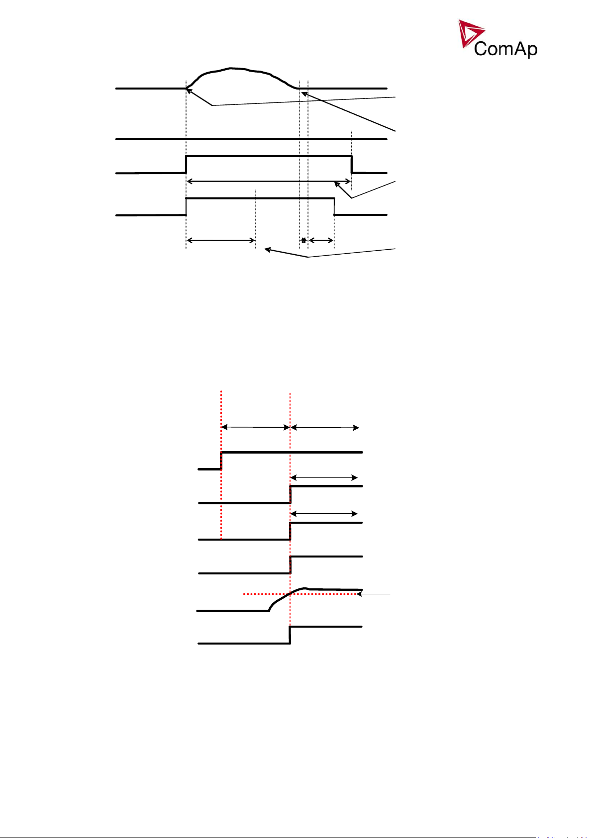
MCB opens on = GENRUN:
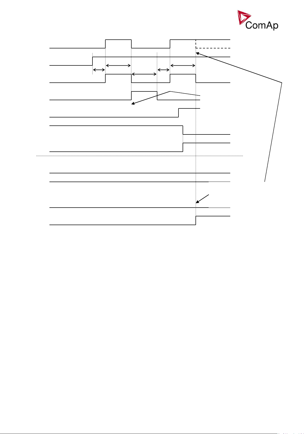
Other CB fail reasons:
When the BO CB close/open is in steady state and CB feedback is changed, the CB fail is detected
immediately (no delay).
When the BO CB close/open opens, there is 5 resp. 2 sec delay for the breaker to respond before a CB
fail is detected. In such case, if CB OFF coil is used for opening the CB and CB fail occurs during
Inteli NT MINT, SW Version 3.0, ©ComAp –May 2013
IGS-NT-MINT-3.0 Reference Guide.PDF
Not valid for MCB:
MCB fail is not detected in this case.
If BI Ext MF relay is active, controller switches to Island
operation. If BI Ext MF relay is not active and Mains is
OK, controller synchronizes back to the mains and tries
to close MCB.
Page 32

32
Alarm: GCB fail
BO GCB close/open
BI GCB feedback
active
opened
opened
Time delay
5 sec
opening the CB, the signal CB OFF coil is automatically extended until the breaker opening is detected
(evaluated as CB status).
2 sec when the CB is used for synchronizing
5 sec in other cases
In case that CB fail is detected after switching the controller on (CB is closed), the CB OFF coil output is
activated immediatelly.
Remote Alarm Messaging
It is possible to use up to five channels for Active Call, Email and SMS upon defined type of Alarm. It is
possible to define protection type for all ENABLED channels to react. All the possibilities in the controller are:
History record, Alarm only, Warning, Mains protect and Mains protect with Reset. Find more information
about alarm types in the chapter Protections and alarm management.
Communication Types for Remote Alarm Messaging
Below there all types of communication available for each Active Call channel.
DATA-ANA: This option sends a complete archive to the recipient's PC via analog modem. An analog
modem must be connected either to one of controller COM ports or to one of I-LB modules connected to the
controller via CAN2 bus. The channel address must contain complete telephone number of the recipient's
PC where InteliMonitor is running in Active call receiving mode.
DATA-GSM: This option sends a complete archive to the recipient's PC via GSM modem. A GSM modem
with activated CSD data transfers must be connected either to one of controller COM ports or to one of I-LB
modules connected to the controller via CAN2 bus. The channel address must contain complete telephone
number of the recipient's PC where InteliMonitor is running in Active call receiving mode.
DATA-ISDN: This option sends a complete archive to the recipient's PC via ISDN modem. An ISDN modem
must be connected either to one of controller COM ports or to one of I-LB modules connected to the
controller via CAN2 bus. The channel address must contain complete telephone number of the recipient's
PC where InteliMonitor is running in Active call receiving mode.
DATA-CDMA: This option sends a complete archive to the recipient's PC via CDMA modem. A CDMA
modem must be connected either to one of controller COM ports or to one of I-LB modules connected to the
controller via CAN2 bus. The local CDMA network must allow point-to-point data transfers. The channel
address must contain complete telephone number of the recipient's PC where InteliMonitor is running in
Active call receiving mode.
SMS-GSM: This option sends a short text message (SMS) containing the actual Alarmlist contents to the
recipient's mobile phone via the GSM modem. The channel address must contain complete telephone
number of the recipient's mobile phone.
SMS-CDMA: This option sends a short text message (SMS) containing the actual Alarmlist contents to the
recipient's mobile phone via the CDMA modem. The channel address must contain complete telephone
number of the recipient's mobile phone.
IB-E-MAIL: This option sends an e-mail containing the actual Alarmlist contents and latest 20 history records
(only date, time, reason) to the recipient's mailbox via the IB-COM module or IG-IB module. The channel
address must contain valid e-mail address of the recipient.
NOTE:
The SMTP settings (SMTP authent,SMTP user name, SMTP password, SMTP address, Contr mailbox) must
be properly adjusted for sending e-mails.
Inteli NT MINT, SW Version 3.0, ©ComAp –May 2013
IGS-NT-MINT-3.0 Reference Guide.PDF
Page 33

33
Example of setting
There is an example of setting of Remote Alarm Messaging. In this case active calls we be triggered on
Mains protect and Mains protect with Reset alarms. Message is sent via email to
emailAddress@domain.com (Channel 1 – available for NTC controller or with any controller with connected
IB-NT or I-LB+), archive is sent via ISDN modem to the number +111222333444 (Channel 2) and SMS is
sent to the number +999111333555 (Channel 3).
It is also possible to adjust number of attempts that controller performs in case of not successful Active Call –
Comms settings:ActCallAttempt. The language of messages can be changed –
Comms settings:Acall+SMS lang (use Translator and Languages tabs in GenConfig to adjust languages).
Up to five channels can be used.
Controller Redundancy
Redundant system is a general term for applications where there are two controllers at each gen-set. One is
the main controller, which controls the gen-set in normal conditions, the other is the redundant controller,
which takes over the control when the main controller fails. Both controllers have identical firmware and most
of the configuration and setpoints. Only several things need to be adjusted/configured differently because of
the rendundancy function itself.
CAUTION!
If there are shared binary or analog outputs used on the controller (e.g. for system start/stop), it is necessary
to prepare the configuration in the way so each controller uses binary or analog output set with different
address. Configuration in gen-set controllers then needs to be altered so it can receive signals from both
controllers (e.g. using built-in PLC functions).
Redundant systems using binary signals
It is not possible to use this redundancy system since correct function of the ccontroller depends on CAN bus
communication and thus CAN redundancy should be always used.
Redundant systems using CAN bus
This system uses the CAN bus for detection whether the main controller is operational or not. If the
redundant controller has not received two consequent messages from the main one (~100ms) it will take
over the system control - it activates the binary output CTRLHBEAT FD, which has to be wired in such a way,
that it disconnects the dead main controller from the control, connects the redundancy controller instead and
activates it by deactivation of the binary input EMERG. MANUAL.
Inteli NT MINT, SW Version 3.0, ©ComAp –May 2013
IGS-NT-MINT-3.0 Reference Guide.PDF
Page 34

34
VPIO
VPI
VPO
CtrlHBeat FD
Emerg. manual
CAN
LOG BOUT
LOG BIN
Watched contr = X
Setpoint
Emerg. manual
LOG BIN
CAN
BOUT
BIN
LOG BIN
MAIN CONTROLLER
REDUNDANT CONTROLLER
Contr. Address = X
Setpoint
As there can be up to 16 pairs of controllers at the CAN bus it is necessary to select which main controller
(address) belongs to which redundant one. The setpoint ProcessControl:Watched Contr is used for this
purpose. It must be adjusted to address of the respective main controller in each redundant controller and it
must be adjusted to 0 in each main controller.
CAUTION!
Correct wiring of all inputs and outputs that should be used both by the main and the redundant controller
needs to be done. Please refer to the corresponding chapter for wiring of binary inputs and outputs.
Do not use Shared Binary Inputs/Outputs for CTRLHBEAT FD -> EMERG.MANUAL connection since the failed
controller may not interpret it correctly!
In the figure above the signal of logical function CtrlHBeat FD is used to disable the main controller if it is lost
from CAN bus or CAN bus communication from that controller becomes erratic. It is used also to disable the
redundant controller when the communication on CAN bus is alright (it is negated). For more information on
Virtual Binary Inputs and Outputs (VPIO) please refer to the chapter about Shared Binary Inputs and Outputs
and Virtual Binary Inputs and Outputs.
NOTE:
Use pulse signals for control of circuit breakers. MCB ON COIL, MCB OFF COIL, MGCB ON COIL and MGCB
OFF COIL should be used to prevent sudden opening for a short period of time when the controller fails and
to ensure proper function of redundancy.
Force value – step by step guide
In this chapter there is complete step by step guide which shows how to use Force value function of the
controller.
Forcing of values is used to change particular setpoint temporarily by activation of related Binary Input. This
is used to change function of controller under given conditions (e.g. there are two different periods during the
day when Export limit given by distribution network is required or not).
WARNING!
Setpoints must not be written continuously (e.g. via Modbus connection)! If continuous change of setpoints
is required, combination of External values and Force value function needs to be used. The memory that
holds setpoints is designed for up to 105 writings. Than memory may be damaged!
Setpoints that are available for forcing may be identified by Force value button on the right side in GenConfig
(see the figure below).
Figure: Example of redundancy function
When the button is clicked, Force value dialog appears.
Inteli NT MINT, SW Version 3.0, ©ComAp –May 2013
IGS-NT-MINT-3.0 Reference Guide.PDF
Page 35

35
Add or remove Force value
Change position of Force value functions (priority)
Change the name of the source setpoint
(available only for Force value 1-16 setpoints)
Select the value that should be forced (i.e.
the value of the particular setpoint)
Rename binary input that
triggers the forcing
ID of binary input
(1 for ForceValueIn 1 etc.)
Select source setpoint or value
For example if we add Force value:Force value 1 to be forced to ProcessControl:Export limit as value 0
(DISABLED) by Binary Input FORCEVALUEIN 1 we can change the function of Export limit from ENABLED to
DISABLED by activation of FORCEVALUEIN 1. It is possible to rename the setpoint to e.g.
Force value:ExportDisabled and Binary Input as well to e.g. DISABLEEXPLIM. The function will not change
(only the corresponding names).
It is possible to use several force value functions for one setpoint. If more than one forcing Binary Input is
active, the one with the highest position (lowest number in the Force value dialog) is used.
It is possible as well to use one Binary Input to force multiple setpoints (e.g. in case of complex function
change).
NOTE:
It is possible only to force value or setpoint in other setpoint if their dimension and range are the same (e.g.
only value with dimension in hours and which is Integer 16 to a setpoint with dimension hours and which is
as well Integer 16). You may use PLC block Convert to change the dimension and range if needed.
Inteli NT MINT, SW Version 3.0, ©ComAp –May 2013
IGS-NT-MINT-3.0 Reference Guide.PDF
Page 36

36
Values for continuous writing from external sources
ONCE
This is a single shot mode. The timer will be activated only once at preset date/time for
preset duration.
DAILY
The timer is activated every "x-th" day. The day period "x" is adjustable. Weekends can
be excluded. E.g. the timer can be adjusted to every 2nd day excluding saturdays and
sundays.
WEEKLY
The timer is activated every "x-th" week on selected weekdays. The week period "x" is
adjustable. E.g. the timer can be adjusted to every 2nd week on monday and friday.
MONTHLY
The timer is activated every "x-th" month on the selected day. The requested day can
be selected either as "y-th" day in the month or as "y-th" weekday in the month. E.g. the
timer can be adjusted to every 1st month on 1st tuesday.
This function is especially designed for continuous writing of setpoints from external sources (e.g. via
Modbus connection).
WARNING!
Setpoints must not be written continuously (e.g. via Modbus connection)! If continuous change of setpoints
is required, combination of External values and Force value function needs to be used. The memory that
holds setpoints is designed for up to 105 writings. Than memory may be damaged!
It is possible to use up to four different External values for continuous writing from external sources. The
values are adjusted by setpoints in Force value group. Default (also initial) value may be adjusted, rate of
change of ExtValueX (by Binary Inputs EXTVALUEX UP and EXTVALUEX DOWN) can be adjusted as well as
high and low limit of the value.
There are two way, how to adjust External values. One is using Binary Inputs mentioned above. Second one
is to write the value directly using e.g. Modbus. External values then may be converted using PLC block
convert and force into setpoint which is then continuously forced (note: NOT WRITTEN) by the value of
ExtValueX. This way internal memory is safe and no damage may occur.
External values are reverted back to their default (initial) value (given by corresponding setpoint) when
Binary Input for their reset is active (and they change to the previous value after Binary Input deactivates).
When the Binary Input is active the External value cannot be changed by Modbus writing or by using Binary
Inputs for up and down value.
NOTE:
External values are not available for external writing when any Binary Input (up, down or reset) related to
them is active.
Note also that when the controller is reset (powered down and up again), all external values are reverted
back to their default (initial) values.
HINT
For information on how to write (or read) objects from controller via Modbus, please refer to the latest
Communication guide for InteliGen and InteliSys.
General Purpose Timers
There is 16 general-purpose timers in the controller, each 4 of them are joined together to one output. That
means there are 4 fully independent timer blocks including 4 timer channels each. The combined outputs
from the timer blocks are TIMERACT 1-4, TIMERACT 5-8, TIMERACT 9-12 AND TIMERACT 13-16.
The timers are intended for scheduling of any operations such as e.g. periodic tests of the gen-set,
scheduled transfer of the load to the gen-set prior to an expected disconection of the mains etc. Each timer
channel can be activated only once within a single day. The activation time and duration of each channel is
adjustable (both as hh:mm).
Timer modes
Available modes of each timer:
Inteli NT MINT, SW Version 3.0, ©ComAp –May 2013
IGS-NT-MINT-3.0 Reference Guide.PDF
Page 37

37
SHORT PERIOD
The timer is repeated with adjusted period (hh:mm). The timer duration is included in
the preriod.
The mode of each timer channel is adjusted by an assigned setpoint. The setpoints are located int the Timer
settings group and can be adjusted via InteliMonitor and GenConfig.
Figure: Principial scheme of one block containing 4 timers
EXAMPLE:
Below is an example how to use the timers for periodic tests of the gen-set performed every sunday with
duration of 30 minutes and also for scheduled transfer of the load before expected mains failure announced
by the local electricity distribution company to 1.5.2010 from 01:00 to 04:00.
1. The output TIMERACT 1-4 is configured internally in GenConfig (LBI tab) to the logical binary
inputs REMOTE TEST and TEST ON LOAD.
2. The setpoint Timer settings:TimerChannel 1 is adjusted to "repeated" mode, "weekly" period, only
sundays, starting date/time next sunday at 0:00, timer duration 0:30 min.
3. The setpoint Timer settings:TimerChannel 2 is adjusted to "once" mode, starting date/time 1.5.2010
at 01:00, timer duration 3:00 hrs.
History Related functions
History Records Adjustment
It is possible to change History records content. Each record contains date, time and cause of the record as
obligatory columns. The rest of columns are configurable.
The history record structure has two parts. The upper part is so-called fast and is written into the history
memory immediately in the moment when the written event occurs. The rest of the record may be written
Inteli NT MINT, SW Version 3.0, ©ComAp –May 2013
IGS-NT-MINT-3.0 Reference Guide.PDF
Page 38

38
with a delay max. 100ms. The fast part is intended for fast changing values as e.g. currents, voltages or
power. The parts are separated by a line in the record content list.
1. Values selection tree
2. Buttons for adding/removing values into/from the record structure
3. Buttons for ordering of the values in the record structure
4. Fast history separator. The fast part is located above the separator
5. Estimated number of records depending on record size
6. Record capacity usage indicator
NOTE:
Values that are displayed in green color are recomended to be placed in the fast part.
If the checkbox Add modules to history automatically.. in the Modules tab is checked then all values of a
module are automatically added into the history record when the module is inserted into the configuration.
Time Stamp function
The controller allows user to define when the history records are written even though there is no other
reason for history record (so called Time Stamp).
It is possible to disable time stamping function (for example when time stamping is not needed and just
floods the history). It may be conditioned by activation of logical Binary Input function (TIME STAMP ACT) or it
may be enabled always.
Period of time stamping may be adjusted from 1 to 240 minutes.
NOTE:
Beware of History flooding by to many Time Stamps (vital information may be overwritten).
Time and Date Intercontroller Sharing
Time and Date are used mainly for History records. These values are shared between controllers that are
connected to CAN. When the value is changed in one controller, it sends its new value to all other controllers
that are connected to the same CAN bus and they update their time and date values and setpoints
accordingly.
Summer Time Mode
Summer Time Mode function may be enabled and disabled by user. It is possible to set if the controller is
located in the northern or southern hemisphere as well.
SummerTimeMode implemented in ComAp controllers is based on CET summer time which means:
Clock goes forward 1 hour at 2:00 a.m. on the last Sunday in March
Clock goes backwards 1 hour at 3:00 a.m. on the last Sunday in Octorber
NOTE:
Please be aware that in other regions summer time adjustments may be done in different time.
Inteli NT MINT, SW Version 3.0, ©ComAp –May 2013
IGS-NT-MINT-3.0 Reference Guide.PDF
Page 39

39
User Buttons
Selects which button is this function mapped to
(0 – first button, 1 – second button and so on)
Choose UserButton index and
its function (ON/OFF etc.)
Choose which colour will be
available for this button
Select which condition triggers
which coulour
Adjust text for the button
when it is active or inactive
ON
Pressing the button changes the state of log. Binary Output USER BUTTON X to closed.
When the output is closed and the button is pressed state is not changed.
OFF
Pressing the button changes the state of log. Binary Output USER BUTTON X to opened.
When the output is opened and the button is pressed state is not changed.
ON/OFF
Pressing the button changes the state of log. Binary Output USER BUTTON X to opened or
closed depending on previous state (it is changed to the opposite state).
PULSE ON
Pressing the button issues log. Binary Output USER BUTTON X to close for one second.
NOTE:
Repeated pressing of button during the closed period (one second) causes issuing other
puls of length of one second to be generated from the moment of button pushing.
There are several User Buttons available in the controller. It is possible to set them on Soft Buttons in
InteliVision 5 or 8.
Available functions for soft buttons are listed in the following table.
HINT
It is possible to lock User Button with password (go to tab Commands in GenConfig). User Buttons 1-5, 6-8
and 9-16 can be locked separately. It is also possible to use User Buttons in SCADA diagrams.
Remote Control Function
It is possible to remotely control several Binary Outputs in the controller. You can either use Remote
Switches tool in InteliMonitor (select Remote switches in menu for corresponding controller), import Remote
Switches tool to a SCADA diagram in Line Diagram Editor or use external device via Modbus (register
#46361 and command #26 (1A hex), for more information on Modbus please refer to the InteliGen/InteliSys
Communication guide).
Remote Switch will activate or deactivate depending on remote control so it can be used to manually control
devices, simulate malfunctions while commissioning etc.
Inteli NT MINT, SW Version 3.0, ©ComAp –May 2013
IGS-NT-MINT-3.0 Reference Guide.PDF
Page 40

40
LBO:RemoteControl1 LBI:Emerg. manual
Remote Switch
command
Vitual Output
Virtual Input
1
2
3
4
5
6
7
8
VPIO module
Figure: Remote Switches tool in InteliMonitor, Remote Switches tools in Line Diagram Editor and Mobus commands
Remote Switches may be easily used to trigger logical Binary Input function and all other related functions as
normal switch on Binary Input. Module VPIO (Virtual Peripheral Inputs- Outputs) can be added to
configuration and it will copy the state of Remote Switch on virtual output to its counterpart virtual input.
Refer to the figure below for example.
Figure: Using of Remote Switches to trigger logical binary inputs
Virtual Peripheral Inputs-Outputs (VPIO) module
For the controller there are several modules available. One of them is Virtual Peripheral Inputs-Outputs
module which is particularly usefull for connection of logical Binary Output functions to logical Binary Input
functions. This way internal controller function may easily trigger other internal controller functions without
unnecessary wiring or usage of PLC functions.
Module is functioning the same way as normal module with 8 outputs and 8 inputs, but the difference is, that
each input copies its counterpart output. It is possible to select any logical Binary Output function for one of
the outputs of VPIO module. Inputs on VPIO module work the same way as standard input of the controller
(i.e. it can be assigned function and protection).
For example of this function please refer to the chapter Remote Control function.
Shared Inputs and Outputs
It is possible to share Binary and Analog values between all the controllers via CAN bus, thus saving
physical Inputs and Outputs and excess wiring.
Inteli NT MINT, SW Version 3.0, ©ComAp –May 2013
IGS-NT-MINT-3.0 Reference Guide.PDF
Page 41

41
SHBOUT (1) SHBIN (1)
SHBOUT (2)
Not Received
Module SHBIN (2) is not
inserted
SHBOUT (3)SHBIN (3)
SHBIN (2)
Not Received
Module SHBIN (3) is not
inserted
Not Received
Module SHBIN (1) is not
inserted
CAN
CAN
Controller 1 Controller 2
Controller 3
Shared Binary Inputs and Outputs may be used exactly in the same way as standard physical Inputs and
Outputs. If SHBIN or SHAIN modules are configured, at least one corresponding module of SHBOUT or
SHAOUT (respectively) is needed. If it is not configured, corresponding protection appears because SHBIN
or SHAIN will be missing. See the figure below for more information.
CAUTION!
For proper function of Shared Binary and Analog Inputs and Outputs, only one source of Shared Binary or
Analog Outputs must be configured (i.e. it is not possible to configure in one controller SHBOUT1 and to
another one as well SHBOUT1).
HINT
Controller sends Shared Binary Outputs each 100ms if there are any changes in any bit position. If there are
no changes, controller sends the information with period 1s.
Figure: Adding of various modules
Figure: Principal Scheme (same for shared Binary I/O and shared Analogue I/O
Inteli NT MINT, SW Version 3.0, ©ComAp –May 2013
IGS-NT-MINT-3.0 Reference Guide.PDF
Page 42

42
SHBIN (1)
SHBOUT (2)
Not Received
Module SHBIN (2) is not
inserted
SHBOUT (3)SHBIN (3)
CAN
Controller 2
Controller 3
Not Transimitted
Module SHBOUT (1) is not
inserted
Level 1, Level 2 or no protection is displayed
DISTBOUT
DISTBIN
-01
DISTBIN
-02
DISTBIN
-03
DISTBIN
-04
Controller CAN 1
DISTBOUT
DISTBIN
-01
DISTBIN
-02
DISTBIN
-03
DISTBIN
-04
Controller CAN 2
DISTBOUT
DISTBIN
-01
DISTBIN
-02
DISTBIN
-03
DISTBIN
-04
Controller CAN 3
DISTBOUT
DISTBIN
-01
DISTBIN
-02
DISTBIN
-03
DISTBIN
-04
Controller CAN 4
CAN communication
Distributed Binary Inputs and Outputs
It is possible to share Binary and Analog values between all the controllers via CAN bus, thus saving
physical Inputs and Outputs and excess wiring.
DISTBIN and DISTBOUT work in a different way than SHBIN and SHBOUT. Each controller has one pack of
eight DISTBOUT available (if not configured or no function is assigned to any output, it does not broadcast
them). The number of DISTBOUT module is not shown in the configuration and it is always corresponding to
the CAN address of the controller (e.g. the controller with address 5 will be broadcasting DISTBOUT-05
which can be received if module DISTBIN-05 is configured in another controller. Up to 32 DISTBIN modules
can be configured (meaning that the controller will be receiving all DISTBOUT from all the controller, even
his own).
It is not possible to change the name of DISTBIN inputs or add protections.
In the example below you can see 4 controllers with various DISTBIN and DISTBOUT configuration.
NOTE:
HINT
Controller sends Distributed Binary Outputs each 100ms if there are any changes in any bit position. If there
are no changes, controller sends the information with period 1s.
NOTE:
DISTBIN and DISTBOUT function is not available for IM-NT-GC controller.
Inteli NT MINT, SW Version 3.0, ©ComAp –May 2013
IGS-NT-MINT-3.0 Reference Guide.PDF
Page 43

43
Modbus Reading and Writing
Controller supports Modbus Slave functions (an external device may write or read from a controller). Modbus
registers corresponding to objects in the controller can be exported to text form in GenConfig.
Figure: Exporting of Modbus registers
If Modbus Master function is required extension module I-CB/Modbus connected via CAN1 can be used. For
more information on how to use this module please refer to InteliGen/InteliSys Communication Guide and to
I-CBEdit manual.
Inteli NT MINT, SW Version 3.0, ©ComAp –May 2013
IGS-NT-MINT-3.0 Reference Guide.PDF
Page 44

44
User Modbus register number
Standard Modbus register number
Communication object number
Value, Setpoint, Alarm state
Select type
Select object
Name of the
Analog Input
Dimension
Connected Sensor
(default and user
sensors)
Resolution and Range of the sensor (in
some cases this is fixed by sensor type
and cannot be changed)
Interpretation of
the received value
in bar graph form
Offset of the
received value
User MODBUS
Users can define Modbus registers from 42873 to 43000. Values, setpoints and Alarm states can be
specified for these new Modbus registers to prepare the Modbus protocol for batch reading and writing or to
standardize Modbus protocol between FW versions or branches.
NOTE:
User MODBUS function is not available for IM-NT-GC controller.
Analog Input Sensors and User Sensors
Controller and/or some extension modules allow connection of sensor outputs to Analog Inputs. There is
whole variety of common sensor output characteristics prepared in configuration by default. Although if there
is sensor that is not in the list, it is possible to prepare custom characteristics (up to 16) with up to 31
definition points.
Figure: Sensor adjustment in GenConfig
Inteli NT MINT, SW Version 3.0, ©ComAp –May 2013
IGS-NT-MINT-3.0 Reference Guide.PDF
Page 45

45
Add or Remove Custom sensor curve
General type of sensor
Custom curve name
Resolution of
converted value
Add or Remove points from the curve
Order values from lowest to highest
Open curve points from file or save
current curve to file
Curve preview (no preview is
displayed if values or their order is
not valid)
Default sensors: PT100/°C, PT1000/°C, NI1000/°C, PT100/°F, PT1000/°F, NI1000/°F,
4-20mA active, 0-2400ohm, 0-2.4V, Tristate
HINT
There is “electronic” type of sensor available for Shared Analog Inputs which can be used to interpret shared
data over CAN bus.
Languages and Translator tool in GenConfig
For detailed description of Languages and Translator tool please refer to GenConfig interactive help (press
F1 when in corresponding tab or open Help -> GenConfig Help).
Power Formats
IGS-NT family allows user to choose from several Power Formats that affect dimensions in which values and
some setpoints are interpreted or adjusted. Power formats may be changed in Miscellaneous tab in
GenConfig. There are following Power Formats available:
1 kW kVAr kVA kX V
0,1 kW kVAr kVA kX V
0,01 MW MVAr MVA MX kV
0,01 MW MVAr MVA MX V
NOTE:
Range of some setpoints and values is changed significantly when different Power Formats are selected.
Last Power Format is designed to be used in combined Power/High Voltage and Low Voltage instalations.
High voltage is then interpreted in Volts (e.g. 33256V instead of 33kV).
Last two Power Formats can be used in combination on one CAN bus.
Figure: User Sensor definition
Inteli NT MINT, SW Version 3.0, ©ComAp –May 2013
IGS-NT-MINT-3.0 Reference Guide.PDF
Page 46

46
System Start/Stop
InteliGen/
InteliSys
InteliGen/
InteliSys
InteliGen/
InteliSys
InteliGen/
InteliSys
BTB feedback
CAN
SHBOUT2 SHBOUT1
SHBIN1
SHBIN2
SHBIN1
SHBIN2
SHBIN1
SHBIN2
SHBIN1
SHBIN2
SHBOUT1-1
Sys Start/Stop
SHBOUT1-2
BTB feedback
InteliMains1
InteliMains2
SHBOUT2-1
Sys Start/Stop
Sys S/S from IM2
BTB feedback
Sys S/S from IM1
M2 Start
(sheet output)
Sys S/S from IM1
BTB feedback
Sys S/S from IM2
M1 Start
(sheet output)
Shared binary inputs
Logical Group 2
Logical Group 1
For proper function of the system, System start and stop signal needs to be used properly. Below there is
scheme that shows how to use the Binary Output SYS START/STOP in the system using just CAN wiring (no
physical wiring is needed to share the starting and stoping signal into all controllers in the system).
Figure: Preparation of correct system start/stop function for two logical groups
Inteli NT MINT, SW Version 3.0, ©ComAp –May 2013
IGS-NT-MINT-3.0 Reference Guide.PDF
Page 47

47
User Mask function
Select the proper function
Show = appears when LBI gets active
Hide = disappears when LBI gets active
None = no function
Select the object
Select which User Mask is used for
this object
In GenConfig you can easily set any object in Screen Editor to show or hide based on activation of particular
Logical Binary Input available for users. Below, there is diagram showing the setup of User Mask function in
Screen Editor.
NOTE:
Masking of screens in InteliVision 5 supports only Show function
Use also other masking functions (masking can react on several internal states, e.g. activation of Timers).
PLC functions
See description in IGS-NT-Application Guide 05-2013.pdf.
Multi language support
NT family controllers support up to five Languages that is possible to switch during controller duty. Every
terminal (i.e. Remote display or PC-InteliMonitor) can be switched to different language. Use PC-GenConfig
- Translator tool to translate texts to another language.
Default application archives contain all texts in English only.
ECU interface customizing
The list of available ECU interfaces can be found in GenConfig / Modules / ECU list.
Inteli NT MINT, SW Version 3.0, ©ComAp –May 2013
IGS-NT-MINT-3.0 Reference Guide.PDF
Page 48

48
Binary selector
J1939 value
ECU command
Governor mode
Isochronous - Droop
Idle Speed select
Idle – Nominal
Frequency select
1500 – 1800
Preheat request
Yes – No
Protection override
Yes – No
Engine params: Bin selector x
Bin selector x
CAN - J1939
Force value: Force value y
Force value y
This function enables to change the following CAN values transmitted to ECU via J1939 or binary output
only. The change can be provided by setpoint or via Binary input. There are four Bin selector channels
available.
Inteli NT MINT, SW Version 3.0, ©ComAp –May 2013
IGS-NT-MINT-3.0 Reference Guide.PDF
Page 49

49
Protections and Alarm management
ANSI CODE
PROTECTION
IG-NT, IG-NTC,
IG-NT-BB, IG-NTC-BB
IS-NT-BB,
IS-NTC-BB
59
Overvoltage
27
Undervoltage
47
Voltage Assymetry
81H
Overfrequency
81L
Underfrequency
50+51
Overcurrent
46
Current Unbalance
32
Overload
50N+64
Earth Fault Current
51N+64
Earth Fault Current, IDMT
32R
Reverse Power
25
Synchronism Check
47
Phase Rotation
37
Undercurrent
@ @
55
Power Factor
@ @
71
Gas (Fuel) Level
40
Excitation Loss
PROTECTION GROUP
CONFIGURABILITY
SETTINGS
Analogu protection
Configurable
Analog protect
Generator
protection
Configurable
Gener protect
Fix protections
Fix
Engine params, Gener protect, Mains protect, Analog
protect
ComAp gen-set controllers provide following range of generator protections.
For each protection adjustable limit and time delay are available.
Note: - excluded; - included
@
- can be created using universal protections
Protection groups
There are two groups of protections in the controller: fix and universal (configurable)
Inteli NT MINT, SW Version 3.0, ©ComAp –May 2013
IGS-NT-MINT-3.0 Reference Guide.PDF
Page 50

50
Alarm types
ALARM/EVENT KIND
LEVEL
DESCRIPTION
Warning
1
The alarm appears in the Alarmlist and is recorded into the history log.
Activates the output Common Wrn as well as the standard alarm outputs.
Alarm Only
1
The alarm appears only in the Alarmlist.
Activates the output Common Al as well as the standard alarm outputs.
HistRecOnly
1
The event is recorded into the history.
Activates the output Common Hst for one second. Standard alarm outputs
are not activated.
AL indication
1
The event is only indicated in the Alarmlist.
It disappear for the alarmist automatically as soon as the cause
disappears.
Standard alarm outputs are not activated.
A+H indication
1
The event is only indicated in the Alarmlist and recorded into the history
log.
It disappear for the alarmist automatically as soon as the cause
disappears.
Standard alarm outputs are not activated.
Shutdown
2
The alarm appears in the Alarmlist and is recorded into the history log.
It causes immediate stop of the gen-set without unloading and cooling
phase.
The gen-set can't be started again while there is a Shutdown alarm in the
Alarmlist.
Activates the output Common Sd as well as the standard alarm outputs.
Slow Stop
2
The alarm appears in the Alarmlist and is recorded into the history log.
It causes stop of the gen-set by the standard stop sequence, i.e. including
unloading and cooling phase.
The gen-set can't be started again while there is a Slow stop alarm in the
Alarmlist.
Activates the output Common Stp as well as the standard alarm outputs.
Off Load
2
The event appears in the Alarmlist and is recorded into the history log. It
does not require confirmation, diappears by itself.
It causes immediate opening of the GCB. In AUT and SEM modes the genset remains running for 60 seconds and then it is stopped by the standard
stop sequence. In MAN mode the gen-set remains running until the
operator changes it's operational state manually.
If the controller is in AUT or SEM mode and all previously active Off load
alarms disappeared the gen-set is automatically started back and
connected to the load if the condition for the gen-set to be running persists
(e.g. Rem start/stop is active ..).
This event is used to put the gen-set temporarily off the load for any
reason.
Activates the output Common OfL.
Inteli NT MINT, SW Version 3.0, ©ComAp –May 2013
IGS-NT-MINT-3.0 Reference Guide.PDF
Page 51

51
Low Power
2
The event appears in the Alarmlist and is recorded into the history log. It
does not require confirmation, diappears by itself.
It causes reduction of the required gen-set load to the Min Power PtM
during parallel-to-mains operation or local baseload operation.
If all previously active Low power alarms disappeared the gen-set is
automatically ramped back to the original required load, which is given
according to the currently active load control mode (Load ctrl PtM) in PtM
operation.
Activates the output Common LoP.
This alarm type is not overriden by the input Sd Override.
Note:
Available in IS-NT only.
BrkOpen&CoolDn
2
The event appears in the Alarmlist and is recorded into the history log.
It causes immediate opening of the GCB (without unloading) and then the
standard stop sequence with cooling follows.
The gen-set can't be started again while there is a BOC alarm in the
Alarmlist.
Activates the output Common BOC as well as the standard alarm outputs.
Sd Override
2
The alarm appears in the Alarmlist and is recorded into the history log.
It causes immediate stop of the gen-set without unloading and cooling
phase.
The gen-set can't be started again while there is a Sd override alarm in the
Alarmlist.
Activates the standard alarm outputs.
This alarm type is not overriden by the input Sd Override.
HINT
The Standard alarm outputs are Alarm and Horn.
Sensor fail detection (FLS)
If the measured resistance, voltage or current on an analog input gets out of valid range, the sensor fail will
be detected and a sensor fail message will appear in the alarmlist. The valid range is defined by the most-left
(RL) and most-right (R
) points of the sensor characteristic ±12.5% from R
H
H-RL
.
HINT
The sensor fail alarm does not influence the gen-set operation
Inteli NT MINT, SW Version 3.0, ©ComAp –May 2013
IGS-NT-MINT-3.0 Reference Guide.PDF
Page 52
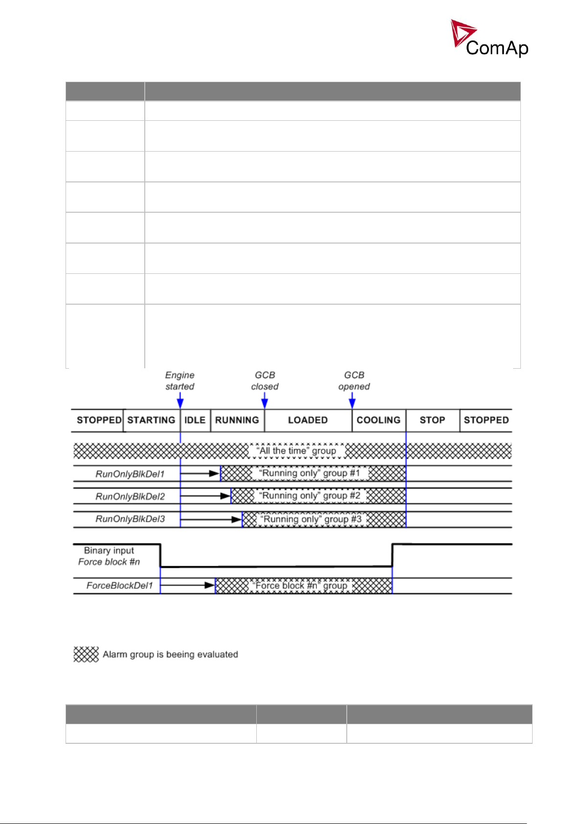
52
Blocking types
BLOCKING TYPE
DESCRIPTION
All the time
The alarms are beeing evaluated all the time the controller is switched on.
RunOnlyBlkDel1
The alarms are beeing evaluated only while the gen-set is running. The evaluation
begins RunOnlyBlkDel1 seconds after the engine has been started.
RunOnlyBlkDel2
The alarms are beeing evaluated only while the gen-set is running. The evaluation
begins RunOnlyBlkDel2 seconds after the engine has been started.
RunOnlyBlkDel3
The alarms are beeing evaluated only while the gen-set is running. The evaluation
begins RunOnlyBlkDel3 seconds after the engine has been started.
Force block 1
The alarms are beeing evaluated while the input Force block 1 is not active. The
evaluation begins ForceBlockDel1 seconds after the input has been deactivated.
Force block 2
The alarms are beeing evaluated while the input Force block 2 is not active. The
evaluation begins ForceBlockDel2 seconds after the input has been deactivated.
Force block 3
The alarms are beeing evaluated while the input Force block 3 is not active. The
evaluation begins ForceBlockDel3 seconds after the input has been deactivated.
El. prot
The alarms are beeing evaluated while the generator is expected to provide correct
voltage and frequency. That means the alarms start to be evaluated after transition
form Idle to Running phase when the period of Max stab time has already elapsed,
remain beeing evaluated while the gen-set is running at nominal speed (regardless
of GCB position) and stop to be evaluated by transition to the Cooling phase.
ENGINE
PROTECTION TYPE
CORESPONDING SETPOINTS
Overspeed
SD
Engine protections: Overspeed
Default protections in MINT
Fix – firmware based protections
Inteli NT MINT, SW Version 3.0, ©ComAp –May 2013
IGS-NT-MINT-3.0 Reference Guide.PDF
Page 53

53
Underspeed
SD
Engine params: Starting RPM
GENERATOR
PROTECTION TYPE
CORESPONDING SETPOINTS
IDMT overcurrent
BOC
Basic settings: Nomin current; Gener
protect: 2Inom del
IDMT Active power
BOC
Gener protect: OverldStrtEval;
2POvrldStrtEvDel
IDMT EarthFault Current
BOC
Gener protect: NomEthFltCurr,
2EthFltCurr del
Shortcurrent
BOC
Gener protect: Ishort; Ishort del
Generator voltage: Ug1>, Ug1<, Ug2>,
Ug2<, Ug3>, Ug3<
BOC
Gener protect: Gen >V BOC; Gen <V
BOC; Gen V del.
Generator voltage: Ug1>>, Ug2>>, Ug3>>
Sd
Gener protect: Gen >V Sd; Gen V del.
Generator frequency: fg<, fg>
BOC
Gener protect: Gen >f; Gen <f; Gen V
del
Excitation Loss
BOC
Gener protect: ExcitationLoss,
ExctLoss del
BUS
PROTECTION TYPE
CORESPONDING SETPOINTS
Bus voltage
MP
Mains protect: Mains >V MP; Mains <V
MP; Mains V del
Bus frequency
MP
Mains protect: Mains >f; Mains <f;
Mains f del
DEFAULT CONFIGURABLE
PROTECTION TYPE
CORESPONDING SETPOINTS
Reverse power (UnivState 1)
BOC
Gener protect: Reverse power;
ReversePwr del
Batt <V, Batt >V (UnivState 2)
Wrn
Analog protect: Batt >V; Batt <V; Batt V
del
Gen Current unbalance
BOC
Gener protect: Gen I unbal; Gen I unb
del
Gen Voltage unbalance
BOC
Gener protect: Gen V unbal;Gen V unb
del
Bus Voltage unbalance
BOC
Mains protect: Mains V unbal; Mains
Vunb del
Basic settings:
VoltProtSelect = PHASE-NEUTRAL
Gener protect: Gen >V BOC
Gen <V BOC
Gen >V Sd
Gen V del
Gen >f
Gen <f
Gen f del
Bus V L1-N
Bus freq
Bus V L2-N
Bus V L3-N
Bus voltage and frequency protections - limits and indications
Inteli NT MINT, SW Version 3.0, ©ComAp –May 2013
IGS-NT-MINT-3.0 Reference Guide.PDF
Page 54

54
Basic settings:
VoltProtSelect = PHASE-PHASE
Gener protect: Gen >V BOC
Gen <V BOC
Gen >V Sd
Gen V del
Gen >f
Gen <f
Gen f del
Bus V L1-L2
Bus V L2-L3
Bus V L3-L1
Bus freq
Basic settings:
VoltProtSelect = PHASE-NEUTRAL
Gener protect: Gen >V BOC
Gen <V BOC
Gen V Sd
Gen V del
Gen >f
Gen <f
Gen f del
BOC L1 under
BOC L2 under
BOC L3 under
BOC L1 over
BOC L2 over
BOC L3 over
Gen V L1-N
BOC fg under
BOC fg over
Gen freq
Gen V L2-N
Gen V L3-N
BOC L12 under
BOC L23 under
BOC L31 under
BOC L12 over
BOC L23 over
BOC L31 over
Gen V L1-L2
BOC fg under
BOC fg over
Gen freq
Gen V L2-L3
Gen V L3-L1
Basic settings:
VoltProtSelect = PHASE-PHASE
Gener protect: Gen >V BOC
Gen <V BOC
Gen V Sd
Gen V del
Gen >f
Gen <f
Gen f del
Generator voltage and frequency protections - limits and indications
Shutdown override
If the Binary input shutdown override (Sd override) is closed, all 2nd level protections are disabled to allow
engine run in an emergency situation, e.g. sprinkler devices power supply.
All protections are shown in Alarmlist and recorded into History, but the controller doesn’t stop the engine
because of them. If the input is deactivated and some protections are still active or not yet reset, the
controller starts to take these protections into account and consequently stops the engine.
HINT
All 2nd level protections are locked out, except of these:
- Emergency stop
- Overspeed
- Underspeed (only if Fuel solenoid = GAS ENGINE)
- Binary and analog protections configured as Sd override type. In fact this protection type means
"Unoverridable shutdown", i.e. it works the same way as standard shutdown protection, however it can not
be overriden (blocked) by the Sd override input.
Inteli NT MINT, SW Version 3.0, ©ComAp –May 2013
IGS-NT-MINT-3.0 Reference Guide.PDF
Page 55

55
Alarm time chart
Ready
RPM=0
LoadedCranking Starting Running
All the time & Overspeed protections & Ig IDMT, Ig unbal, Ig short
Mains >V, Mains <V, Mains >f, Mains <f, MVolt unbal
Gen>V, Gen<V, Gen>f, Gen<f,
Volt unbal, Curr unbal, Reverse
power, Unload protection, Load surge
GCB opened
Engine running only, SD, Slow stop, Wrn
Underspeed
Stop
Start
Starter OFF
Protection
delay
Idle
Min stab time
GCB closed
or
Max stab time
Loaded
Synchronizing
Unloading
Cooling
Gen-set operating states
Protections - evaluation depends on the gen-set state
- depends on the actual gen-set conditions
Enable/Disable protection for this input
Name of the binary input is also
used as the name of the protection
Type of protection
Toggle normally closed/normally open
Defines when the protection is active
Defines protection delay
Configuration of User configurable protections in GenConfig
It is possible to configure protections on Binary Input, Analog Input or any value that is available in the
controller.
Binary Input protection configuration
Open I/O tab in GenCofig and adjust parameters that are described below.
Analog Input protection configuration
Open I/O tab in GenCofig and adjust parameters that are described below.
Inteli NT MINT, SW Version 3.0, ©ComAp –May 2013
IGS-NT-MINT-3.0 Reference Guide.PDF
Page 56

56
Enable/Disable protection for
this input
Level 1 protection type
Level 2 protection type
Sensor fail protection ON/OFF
Protection is written to the
history
- alway = when it is trigged
- once = only when it is trigged
for the first time
Defines when the protection
is active
User custom setpoint for
level 1 limit (enables when
level 1 protection type is
selected)
User custom setpoint for
level 2 limit (enables when
level 2 protection type is
selected)
Delay of the protection
evaluation for both levels
(enables when at least one
protection type is selected)
Existing custom protections
list
Add protection
Delete protection
Select the value for the
protection
Select the protection type
Select if the protection is
under or over limit and if it
should have fail sensor
protection
Defines when the protection
is active
Add new message for
protections
Select message from existing
ones
Select
protection group
(setpoints for
this protection
will be placed in
corresponding
group)
Select wheter the
protection should be
evaluated each 100ms
or each 20 ms.
Protection is
written to the
history
- alway = when it is
trigged
- once = only when
it is trigged for the
first time
Select whether new setpoint should
be created to limit the protection or
an existing one should be used or if
the limit should be constant
Limit the new setpoint value range
Select whether new setpoint should
be created todelay the protection
or an existing one should be used or
if the delay should be constant
HINT
Fail Sensor protection (when activated) does not affect the function of the system itself. If you adjust “Active
when” to Under limit + Fls or Over limit + Fls the protection will considered the value that is out of range
(failed sensor) to be under or over limit (depending on the setting) and it will issue corresponding alarm after
the delay of the protection. This can be used for example when the function of the particular sensor
connected to an analog input is crucial for the operation of the system and its failure requires the system to
be affected (open breakers etc.).
Custom configurable protection
Open Protections tab in GenCofig and adjust parameters that are described below.
HINT
You need to prepare two separate protections for level 1 and level 2.
Select the value for protection first and then use Wizard – it will take you through all the steps and help you
adjust them correctly.
Inteli NT MINT, SW Version 3.0, ©ComAp –May 2013
IGS-NT-MINT-3.0 Reference Guide.PDF
Page 57

57
Reset Actual Alarms selection
DISABLED
Pressing of the fault reset button (at any terminal or external button) resets
only inactive alarms. Active alarms remain in the alarmlist unchanged and must be reset
again when they become inactive.
ENABLED
Pressing of the fault reset button (at any terminal or external button) resets all alarms that
are currently present in the alarm list. Inactive alarms disappear from the alarm list
immediately, active alarms are changed to "confirmed" state and disappear when the
alarm condition disappear or the alarm starts to be blocked.
It is possible to determine the behavior of alarms that are in alarm list when Fault Reset button is pressed.
Select behavior with ComProtSetting:ResetActAlarms.
NOTE:
ENABLED position corresponds to the method how the IG-classic and IS-classic controllers handled the
alarms.
Inteli NT MINT, SW Version 3.0, ©ComAp –May 2013
IGS-NT-MINT-3.0 Reference Guide.PDF
Page 58

58
Gen-set operation states
GEN-SET STATE
DESCRIPTION
Init
Controller is powerd up and configuration setting is initialized
Not ready
Gen-set is not ready to start or is not allowed to start
Ready
Gen-set is ready to run, all condition for start are fulfilled
Prestart
Prestart sequence in process. From closing of Prestart output to closing
of Starter output
Cranking
Engine is cranking and the starter output is closed
Pause
Pause between start attempts is counting down
Starting
Starting RPM is reached
Running
Gen-set is running and waiting for GCB connection
Warming
Gen-set is running in parallel operation and gen-set load is reduced to
Warming load
Soft load
Gen-set power is ramping up
Loaded
Gen-set is loaded
Soft unld
Gen-set power is ramping down
Cooling
State after GCB was opened and engine is not stopped
Stop
Engine is stopped
Shutdown
Shutdown alarm activated
Ventil
Gas engine – ventilation of unburned fuel when stop command comes
during cranking with gas
SDVentil
Gas engine – ventilation of unburned fuel after unsuccessful start attempt
Off load
GCB is opened, gen-set keeps running on nominal RPM
Emerg man
Emergency manual state
Gen-set can operate in following states
GEN-SET OPERATION STATES
Inteli NT MINT, SW Version 3.0, ©ComAp –May 2013
IGS-NT-MINT-3.0 Reference Guide.PDF
Page 59

59
GEN-SET CONDITIONS
DESCRIPTION
IslOper
Island operation (MCB is opened, GCB is closed)
Brks Off
GCB, MCB opened
MainsOper
Mains is present (MCB is closed, GCB is opened)
Synchro
Gen-set is synchronizing (MCb is closed, GCB is opened)
ParalOper
Gen-set is in parallel with mains (MCB is closed, GCB is closed)
MainsOper/Brk Off
Engine is running idle
GEN-SET EXTERNAL CONDITIONS
Inteli NT MINT, SW Version 3.0, ©ComAp –May 2013
IGS-NT-MINT-3.0 Reference Guide.PDF
Page 60

60
Inputs and Outputs
Module
name
BIN
BOUT
AIN
AOUT
IMPULSE
Note
IGS-NT
controller
x x x x
Number of I/O depends on type.
IGS-PTM
8 8 4 1 -
Standard I/O extension module.
IS-AIN8
- - 8 - -
Standard I/O extension module.
IS-AIN8TC
- - 8 - -
8 thermocouple inputs
IS-BIN16/8
16 8 - - -
Standard I/O extension module.
InteliAIN8
- - 8 - 2
InteliAIN8TC
- - 8 - -
InteliIO8/8
8 8 - 2 -
InteliIO16/0
16 0 - 2 -
I-CB
x x x x -
Configurable communication bridge.
IGL-RA15
-
15 - - - 15 Green, Red, Yellow LED panel.
I-AOUT8
- - - 8 -
8 Analog outputs
VPIO
8 8 - - -
Virtual periphery I/O module.
SHBIN
8 - - - -
SHared (virtual) Binary INput module
SHBOUT
- 8 - - -
SHared (virtual) Binary OUTput module
SHAIN
- - 8 - -
Shared (virtual) Analog INput module
SHAOUT
- - - 8 -
Shared (virtual) Analog OUTput module
PLC x x x x - Programmable (internal) logic module.
Virtual and physical modules
Number of I/O can be extended and project wiring can be reduced using the following extension and virtual
modules.
HINT
For more details about Virtual peripherals (Shared and Internal virtual I/O periphery and PLC) see IGS-NTApplication guide-2.4.pdf.
CAUTION!
Usage of any 3rd-party peripheral modules in cooperation with ComAp controller is not recommended.
ComAp can’t guarantee the proper function of controller with none-ComAp peripheral modules.
Inteli NT MINT, SW Version 3.0, ©ComAp –May 2013
IGS-NT-MINT-3.0 Reference Guide.PDF
Page 61

61
Setpoints
Setpoints are analog, binary or special data objects, that are used for adjusting the controller to the specific
environment. Setpoints are collected to groups according to their meaning. Setpoints can be adjusted from
the controller front panel, PC, MODBUS etc.
Password protection
Any setpoint can be password protected - 7 levels of protection are available. There can be up to 8 users
defined, each one with different access rights (levels of protection). Every user has it’s own password. The
password is a four-digit number. Only setpoints protected by the protection level that is covered by currently
logged-in user’s access rights can be modified.
If a user logs in from a particular terminal (e.g. the controller front panel), this does not unlock the other
terminals for him, e.g. InteliMonitor connected directly or via modem.
Setpoints opened from front panel are automatically closed 15 minutes (return to measurement screens)
after the last setpoint change or when wrong value of password is set.
System administrator (User 0 – always present in the system) can reset the password for any other user.
The controller programming (configuration) requires the highest - password 7 level, so only User 0 is able to
modify the controller configuration or firmware.
Continuous internal evaluation of setpoints validity
In case of detection of Setpoints checksum (validity) evaluation error, the Shutdown alarm “Setpoint CS
error” is issued to prevent the controller to run the engine with incorrect setting. The evaluation is provided at
controller startup and continuously during the standard operation. I.e. in case of detection of such error, the
engine is shut down immediatelly.
Setpoint synchronization
Setpoints, that are marked with "#" sign at the begin of their names, are synchronized with other controllers
present on the CAN bus line, i.e. the system will ensure that the respective setpoint will have identical value
in each connected controller. If the setpoint is changed in one controller, the same change will occur in all
other controllers. This function is necessary especially for MINT application, where the system of Power
management is based on fact that the respective setpoints are identical in all controllers.
CAUTION!
Do not perform repeated writing of setpoints (e.g. power control from a PLC by repeated writing of baseload
setpoint via Modbus) The setpoints are stored in EEPROM memory, which can be overwritten up to 105
times without risk of damage or data loss, however it may become damaged, when allowed number of
writing cycles is exceeded!
Inteli NT MINT, SW Version 3.0, ©ComAp –May 2013
IGS-NT-MINT-3.0 Reference Guide.PDF
Page 62

62
List of possible events
The complete list is available in Troubleshooting guide.
Inteli NT MINT, SW Version 3.0, ©ComAp –May 2013
IGS-NT-MINT-3.0 Reference Guide.PDF
Page 63

63
Controller configuration and monitoring
5 - GND
2 - RxD
3 - TxD
PC
5 - GND
2 - RxD
3 - TxD
RS232
RS232
230 VAC
0 VDC
CONTROLLER
+
-
Battery
Required the same
voltage potential
betw een GND ‘s
RS 232
IGS-NT istallation pack contains separate PC software tools: GenConfig (GC) and InteliMonitor (IM).
GC and IM are based on Windows 95/98/NT/ME/2000/XP or higher platform and require approximately 30
Mbyte of hard disc free space.
Direct connection to the PC
IGS-NT controller can be connected directly with PC via RS232 or USB interface. Use the crossed RS232 or
USB cable to connect PC with controller.
HINT
Make sure the grounding system on controller and PC – COM port (negative of the PC DC supply) are
identical – before the first direct connection. There must not be any voltage between these two points
otherwise the internal PTC protection activates and interrupts RS232 communication. In such case
disconnect RS232 line wait a minute for PTC recovery and try again. The simple solution is to assure, that
the PC supply 240/20V is ground free (GND terminal is not connected).
GenConfig functions
Extension modules addressing
All I/O function or protection configuration
Setpoints adjusting
Sensor characteristics modification
History record modification
Password level protection modification (password value must be changed in DriveMonitor)
Controller firmware (mhx file) upgrade
Controller application file Up/Down load
Language translator enables
o Create Dictionary between two languages (Dictionary can be used repeatedly)
o Translate current text in Controller (in any language)
o Add new language (up to five)
Configuration steps
Following configuration steps are available in GenConfig software:
Select Extension modules when more inputs and outputs are required
Configure J1939 interface when Electronic engine is connected
Configure Binary inputs as Protection or Function
Configure Binary outputs
Configure Analog inputs as Protection or Function
Define user sensors
Configure History record
Configure password protection
Add/Translate the language
Inteli NT MINT, SW Version 3.0, ©ComAp –May 2013
IGS-NT-MINT-3.0 Reference Guide.PDF
Page 64

64
InteliMonitor
Code page
Language
Windows code
0
West European languages
Windows 1252
134
Chinese
GB 2312
162
Turkish
Windows 1254
129
Korean
Windows 1258
204
Russian
Windows 1251
238
East European languages
Windows 1250
Functions
On-line direct, Modem or Internet single or multiple engine monitoring
Active Modem or Internet call from the controller to PC (activated by selected Alarm)
On-line or Off-line History record listing
Setpoints listing and adjusting (password protected)
Statistics value (e.g. Running hours) Set/Reset
Password and Access code change
Modbus protocol
Standard protocol enables receive/transmit any data or command from a Master system:
Direct connection: RS232, RS422, RS485
Modem connection
9600, 19200, 38400 or 57600 bps, 8 data bits, 1 stop bit, no parity
Transfer mode RTU
Function 3 (Read Multiply Registers)
Function 6 (Write Single Register)
Function 16 (Write Multiply Registers)
The response to an incoming message depends on the communication speed. The delay is not shorter
than the time needed to send/receive 3 and ½ characters.
The complete description of Modbus communication protocol can be found in Modbus Protocol Reference
Guide PI-MBUS-300 and Open Modbus Specification Release 1.0. Both documents are available from web
site at http://www.modicon.com/openmbus/ .
HINT
Detail Modbus command description see in ComAp InteliCommunication guide.
Value and setpoint codes
HINT
It is possible to export actual values, setpoints and history file on-line from the controller or off-line from the
archive using InteliMonitor – Monitor – Export data… function.
Technical data
HINT
Technical data of the controller and extension modules find in the IGS-NT-Installation guide-x.y.pdf.
Language support
IG-NT from display firmware version 1.4 supports following language code pages:
Inteli NT MINT, SW Version 3.0, ©ComAp –May 2013
IGS-NT-MINT-3.0 Reference Guide.PDF
Page 65

65
Code page
Language
Windows code
0
West European languages
Windows 1252
134
Chinese
GB 2312
162
Turkish
Windows 1254
129
Korean
Windows 1258
136
Thailand
GB 2312
204
Russian
Windows 1251
238
East European languages
Windows 1250
IS-NT display from firmware version 1.5 supports following language code pages:
Inteli NT MINT, SW Version 3.0, ©ComAp –May 2013
IGS-NT-MINT-3.0 Reference Guide.PDF
Page 66

66
APPENDIX
Inteli NT MINT, SW Version 3.0, ©ComAp –May 2013
IGS-NT-MINT-3.0 Reference Guide.PDF
Page 67

67
Setpoint groups
1. ProcessControl
2. Basic settings
3. Comms settings
4. Engine params
5. Engine protect
6. Analog protect
7. Gener protect
8. Pwr Management
9. Sync/Load ctrl
10. Volt/PF ctrl
11. Force value
12. Load shedding
13. Timer settings
14. Act. calls/SMS
15. Date/Time
CAUTION!
Do not perform repeated writing of setpoints (e.g. power control from a PLC by repeated writing of baseload
setpoint via Modbus) The setpoints are stored in EEPROM memory, which can be overwritten more than 105
times without risk of damage or data loss, but it may become damaged, when allowed number of writing
cycles is exceeded!
Setpoints - SMS/E-Mail
1. History record
2. Alarm only
3. Warning
4. Off load
5. BrkOpen CoolDn
6. Mains protect
7. Slow stop
8. Shutdown
9. ShutdownOvr
10. AcallCH1-Type
11. AcallCH1-Addr
12. AcallCH2-Type
13. AcallCH2-Addr
14. AcallCH3-TYPE
15. AcallCH3-Addr
16. AcallCH4-TYPE
17. AcallCH4-Addr
18. AcallCH5-TYPE
19. AcallCH5-Addr
20. NumberRings AA
21. ActCallAttempt
22. Acall+SMS Lang
Setpoints - Analog protect
1. Batt >V
2. Batt <V>
Inteli NT MINT, SW Version 3.0, ©ComAp –May 2013
IGS-NT-MINT-3.0 Reference Guide.PDF
Page 68

68
3. Batt volt del
Setpoints - Basic Settings
1. Nomin Power
2. Nomin current
3. CT ratio prim
4. CT ratio sec
5. EarthFltCurCTp
6. Im3/ErFlCurCTs
7. VT ratio
8. Vg InpRangeSel
9. Vb VT ratio
10. Vm InpRangeSel
11. GenNomV
12. GenNomVph-ph
13. BusNomV
14. BusNomVph-ph
15. FixVoltProtSel
16. Nominal Freq
17. Nom frq offset
18. Gear Teeth
19. Nominal RPM
20. ControllerMode
21. FltRes GoToMAN
22. Local buttons
23. DispBaklightTO
24. DispBklStrtOff
25. FastHistPeriod
26. ConvCoefPulse1
27. ConvCoefPulse2 (for IS-NT only)
28. ConvCoefPulse3 (for IS-NT only)
29. ConvCoefPulse4 (for IS-NT only)
Setpoints - Comms settings
1. Gen-set name
2. Contr. address
3. RS232(1) mode
4. RS232(2) mode
5. RS232(1)MBCSpd
6. RS232(2)MBCSpd
7. RS232(1)MdmIni
8. RS485(1) conv.
9. RS485(2) conv.
10. RS232(2)MdmIni
11. CAN bus mode
12. CAN2emptDetect
13. LB/UART Log
14. CANAddrSwitch1
15. CANAddrSwitch2
16. IP Addr mode
17. IP address
18. Net mask
19. Gateway IP
20. ComApProtoPort
21. AirGate
22. AirGate IP
Inteli NT MINT, SW Version 3.0, ©ComAp –May 2013
IGS-NT-MINT-3.0 Reference Guide.PDF
Page 69

69
23. SMTP authent
24. SMTP user name
25. SMTP password
26. SMTP address
27. Contr mailbox
28. Time zone
29. DNS IP
30. ECU Diag
31. SHxOcol detect
Setpoints - Date/Time
1. Time stamp act
2. Time Stamp Per
3. #SummerTimeMod
4. #Time
5. #Date
Setpoints - Engine Params
1. Starting RPM
2. Starting POil
3. Prestart time
4. Prelubr time
5. Prelubr pause
6. MaxCrank time
7. CrnkFail pause
8. Crank attempts
9. Idle time
10. Min stab time
11. Max stab time
12. Warming load
13. Warming temp
14. Max warm time
15. Cooling speed
16. Cooling time
17. CoolDnAfterBOC
18. Cooldown optim
19. AfterCool time
20. Stop time
21. SDVentil time
22. Fuel solenoid
23. FuelSol offset
24. D+ Function
25. Bin selector 1
26. Bin selector 2
27. Bin selector 3
28. Bin selector 4
29. MaxLevelDrop
Setpoints - Engine Protect
1. Horn timeout
2. RunOnlyBlkDel1
3. RunOnlyBlkDel2
4. RunOnlyBlkDel3
Inteli NT MINT, SW Version 3.0, ©ComAp –May 2013
IGS-NT-MINT-3.0 Reference Guide.PDF
Page 70

70
5. BinInp delay 1
6. BinInp delay 2
7. BinInp delay 3
8. ForceBlockDel1
9. ForceBlockDel2
10. ForceBlockDel3
11. ResetActAlarms
12. Overspeed
13. Service time 1
14. Service time 2
15. Service time 3
16. Service time 4
17. Max+CylDifPmin(for IS-NT only)
18. Max-CylDifPmin(for IS-NT only)
19. Max+CylDifPnom(for IS-NT only)
20. Max-CylDifPnom(for IS-NT only)
21. PminCylDifEval(for IS-NT only)
22. CylDifEvalDel(for IS-NT only)
Setpoints - Force value
1. Force value 1
2. Force value 2
3. Force value 3
4. Force value 4
5. Force value 5
6. Force value 6
7. Force value 7
8. Force value 8
9. Force value 9
10. Force value 10
11. Force value 11
12. Force value 12
13. Force value 13
14. Force value 14
15. Force value 15
16. Force value 16
17. ExtValue1LoLim
18. ExtValue2LoLim
19. ExtValue3LoLim
20. ExtValue4LoLim
21. ExtValue1HiLim
22. ExtValue2HiLim
23. ExtValue3HiLim
24. ExtValue4HiLim
25. ExtValue1 rate
26. ExtValue2 rate
27. ExtValue3 rate
28. ExtValue4 rate
29. ExtValue1deflt
30. ExtValue2deflt
31. ExtValue3deflt
32. ExtValue4deflt
Setpoints - Gener Protect
1. OverldStrtEval
2. 2PovrldStEvDel
Inteli NT MINT, SW Version 3.0, ©ComAp –May 2013
IGS-NT-MINT-3.0 Reference Guide.PDF
Page 71

71
3. Min Power PtM
4. Ishort
5. Ishort del
6. 2Inom del
7. Gen >V BOC
8. Gen <V BOC
9. Gen >V Sd
10. Gen V del
11. Gen >f
12. Gen <f
13. Gen f del
14. BusMeasError
15. Reverse power
16. ReversePwr del
17. ExcitationLoss
18. ExctLoss del
19. EarthFaultCurr
20. EthFltCurr del
21. Gen V unbal
22. Gen V unb del
23. Gen I unbal
24. Gen I unb del
25. Bus V unbal
26. Bus V unb del
Setpoints - Load shedding
1. Ld shed active
2. Ld shed level
3. Ld shed delay
4. Ld recon level
5. Ld recon delay
6. AutoLd recon
Setpoints - Power Management
1. Pwr management
2. #Pwr mgmt mode
3. Priority
4. #PriorityAutoSwap
5. Priority ctrl
6. #SysAMFstrtDel
7. #SysAMFstopDel
8. #LoadResStrt 1
9. #LoadResStop 1
10. #LoadResStrt 2
11. #LoadResStop 2
12. #LoadResStrt 3
13. #LoadResStop 3
14. #LoadResStrt 4
15. #LoadResStop 4
16. #%LdResStrt 1
17. #%LdResStop 1
18. #%LdResStrt 2
19. #%LdResStop 2
20. #%LdResStrt 3
21. #%LdResStop 3
22. #%LdResStrt 4
Inteli NT MINT, SW Version 3.0, ©ComAp –May 2013
IGS-NT-MINT-3.0 Reference Guide.PDF
Page 72

72
23. #%LdResStop 4
24. #NextStrt del
25. #OverldNextDel
26. #NextStopDel
27. #SlowStopDel
28. #MinRunPower 1
29. #MinRunPower 2
30. #MinRunPower 3
31. RunHoursBase
32. #RunHrsMaxDiff
33. #PwrBandContr1
34. #PwrBandContr2
35. #PwrBandContr3
36. #PwrBandContr4
37. #PwrBnChngDlUp
38. #PwrBnChngDlDn
39. Control group
40. GroupLinkLeft
41. GroupLinkRight
Setpoints - Process Control
1. #SysBaseLoad
2. LocalBaseload
3. #SysPwrFactor
4. #SysLdCtrl PtM
5. #SysPFCtrl PtM
6. SysBaseLdMode
7. SysBasePFMode
8. Derating1 strt (IS-NT only)
9. Derating2 strt (IS-NT only)
10. Derating1 end (IS-NT only)
11. Derating2 end (IS-NT only)
12. Derated1 pwr (IS-NT only)
13. Derated2 pwr (IS-NT only)
14. #Neutral cont
15. Watched contr
Setpoints - Sync/load Ctrl
1. SpeedRegChar
2. Voltage window
3. GtoM AngleReq
4. Dwell time
5. Freq gain
6. Freq int
7. Freq reg loop
8. Angle gain
9. Speed gov bias
10. SpdGovPWM rate
11. SpeedGovLowLim
12. SpeedGovHiLim
13. TauSpeedActuat
14. Load ramp
15. Load gain
16. Load int
17. RampStartLevel
18. GCB open level
Inteli NT MINT, SW Version 3.0, ©ComAp –May 2013
IGS-NT-MINT-3.0 Reference Guide.PDF
Page 73

73
19. GCB open del
20. Sync timeout
21. LS gain
22. LS int
Setpoints - Timer settings
1. TimerChannel 1
2. TimerChannel 2
3. TimerChannel 3
4. TimerChannel 4
5. TimerChannel 5
6. TimerChannel 6
7. TimerChannel 7
8. TimerChannel 8
9. TimerChannel 9
10. TimerChannel 10
11. TimerChannel 11
12. TimerChannel 12
13. TimerChannel 13
14. TimerChannel 14
15. TimerChannel 15
16. TimerChannel 16
Setpoints - Volt/PF Control
1. AVRRegChar
2. Voltage gain
3. Voltage int
4. PF gain
5. PF int
6. AVR DCout bias
7. VS gain
8. VS int
9. TauVoltActuat
Inteli NT MINT, SW Version 3.0, ©ComAp –May 2013
IGS-NT-MINT-3.0 Reference Guide.PDF
Page 74

74
Value groups
1. Analog CU
2. Bin inputs CU
3. Bin outputs CU
4. Engine values
5. Force value
6. Gener values
7. Info
8. Log Bout
9. Load shedding
10. Bus values
11. Power management
12. Statistics
13. Sync/Load ctrl
14. Volt/PF ctrl
Values group - Analog CU
1. Ubat
2. CPU temp
3. D+
4. AIN CU-1
5. AIN CU-2
6. AIN CU-3
7. AIN CU-4
Values group - Bin inputs CU
1. BIN
Values group - Bin outputs CU
1. BOUT
Values group - Engine values
1. RPM
2. T Cyl aver
3. T Cyl max
4. T Cyl min
Values group - Force value
1. ExtValue1
2. ExtValue2
3. ExtValue3
4. ExtValue4
Inteli NT MINT, SW Version 3.0, ©ComAp –May 2013
IGS-NT-MINT-3.0 Reference Guide.PDF
Page 75

75
Values group - Gener values
1. Act power
2. Act pwr L1
3. Act pwr L2
4. Act pwr L3
5. React power
6. React pwr L1
7. React pwr L2
8. React pwr L3
9. Appar pwr
10. Appar pwr L1
11. Appar pwr L2
12. Appar pwr L3
13. Pwr factor
14. Load char
15. Pwr factor L1
16. Load char L1
17. Pwr factor L2
18. Load char L2
19. Pwr factor L3
20. Load char L3
21. Gen freq
22. Gen V L1-N
23. Gen V L2-N
24. Gen V L3-N
25. Gen V
26. Gen curr L1
27. Gen curr L2
28. Gen curr L3
29. Gen V unbal
30. Gen I unbal
31. Slip freq
32. Angle
Values group - Info
1. Controller mode
2. SW version
3. Application
4. SW branch
5. Password decode
6. CAN16
7. CAN32
8. Reg16
9. Reg32
10. Engine state
11. Breaker state
12. Timer text
13. Timer val
14. ECU DiagSource
15. NextTime1-4
16. NextDate1-4
17. NextTime5-8
18. NextDate5-8
19. NextTime9-12
20. NextDate9-12
21. NextTime13-16
Inteli NT MINT, SW Version 3.0, ©ComAp –May 2013
IGS-NT-MINT-3.0 Reference Guide.PDF
Page 76

76
22. NextDate13-16
23. AirGate ID
24. AirGate status
Values group - Log Bout
1. LogBout 1
2. LogBout 2
3. LogBout 3
4. LogBout 4
5. LogBout 5
6. LogBout 6
7. LogBout 7
8. LogBout 8
9. RemoteControl
Values group - Load shedding
1. StatLdShed
Values group - Bus values
1. Bus freq
2. Bus V L1-N
3. Bus V L2-N
4. Bus V L3-N
5. Bus V
6. Bus V L1-L2
7. Bus V L2-L3
8. Bus V L3-L1
9. Bus V unbal
10. EarthFC
Values group - Power management
1. EnginePriority
2. Act Reserve
3. Reserve
4. Reserve Stp
5. ActRes rel
6. Res rel
7. ResStp rel
8. MinR PWR
Values group - Statistics
1. kWhours
2. kVArhours
3. Run hours
4. Num starts
5. NumUnsc start
6. Service time 1
7. Service time 2
8. Service time 3
Inteli NT MINT, SW Version 3.0, ©ComAp –May 2013
IGS-NT-MINT-3.0 Reference Guide.PDF
Page 77

77
9. Service time 4
10. Total downtime
11. DnTimeReqToRun
12. PulseCounter 1
13. PulseCounter 2
14. PulseCounter 3
15. PulseCounter 4
Values group - Sync/Load ctrl
1. ActPwrReq
2. SpdRegOut
3. Speed request
4. SpeedReq RPM
5. ReqEngineSpeed
6. SystLoadCtrl
7. TotRunPact Q
8. TotRunPact P
9. netPgnomPh
Values group - Volt/PF ctrl
1. VoltRegOut
2. SystPfCtrl
Inteli NT MINT, SW Version 3.0, ©ComAp –May 2013
IGS-NT-MINT-3.0 Reference Guide.PDF
Page 78

78
Binary input functions
1. Sys start/stop
2. Emergency stop
3. Nominal speed
4. PrestartBypass
5. Oil press
6. Sd override
7. Emerg. manual
8. RunIndication 1
9. RunIndication 2
10. RunIndication 3
11. GCB feedback
12. GCB fdb neg
13. MCB feedback
14. MCB fdb neg
15. NeutralCB fdb
16. AccessLock int
17. AccessLock D#2
18. AccessLock D#3 (for IS-NT only)
19. AccessLock ext
20. Remote OFF
21. Remote MAN
22. Remote AUT
23. Force block 1
24. Force block 2
25. Force block 3
26. Load res 2
27. Load res 3
28. Load res 4
29. MinRun power 1
30. MinRun power 2
31. MinRun power 3
32. Priority sw A
33. Priority sw B
34. Priority sw C
35. Priority sw D
36. GroupLink
37. StartButton
38. StopButton
39. FaultResButton
40. HornResButton
41. GCBButton
42. ManualLdRecon
43. GCB disable
44. Alt brightness
45. IssueActCallC1
46. IssueActCallC2
47. IssueActCallC3
48. ECUComFailBlck
49. Startblocking
50. ECU StoppedEng
51. CtrlHBeat sens
52. Force value 1
53. Force value 2
54. Force value 3
55. Force value 4
56. Force value 5
Inteli NT MINT, SW Version 3.0, ©ComAp –May 2013
IGS-NT-MINT-3.0 Reference Guide.PDF
Page 79

79
57. Force value 6
58. Force value 7
59. Force value 8
60. Force value 9
61. Force value 10
62. Force value 11
63. Force value 12
64. Force value 13
65. Force value 14
66. Force value 15
67. Force value 16
68. CylDifEvalBlk (for IS-NT only)
69. ExtValue1 up (for IS-NT only)
70. ExtValue2 up (for IS-NT only)
71. ExtValue3 up (for IS-NT only)
72. ExtValue4 up (for IS-NT only)
73. ExtValue1 down (for IS-NT only)
74. ExtValue2 down (for IS-NT only)
75. ExtValue3 down (for IS-NT only)
76. ExtValue4 down (for IS-NT only)
77. ExtValue1reset
78. ExtValue2reset
79. ExtValue3reset
80. ExtValue4reset
81. PulseCounter 1 (for IS-NT only)
82. PulseCounter 2 (for IS-NT only)
83. PulseCounter 3 (for IS-NT only)
84. PulseCounter 4 (for IS-NT only)
85. Timer block 1
86. Timer block 2
87. Timer block 3
88. Timer block 4
89. Timer block 5
90. Timer block 6
91. Timer block 7
92. Timer block 8
93. Timer block 9
94. Timer block 10
95. Timer block 11
96. Timer block 12
97. Timer block 13
98. Timer block 14
99. Timer block 15
100. Timer block 16
101. Lang sel int A
102. Lang sel int B
103. Lang sel int C
104. Lang sel D#2 A
105. Lang sel D#2 B
106. Lang sel D#2 C
107. Lang sel D#3 A (for IS-NT only)
108. Lang sel D#3 B (for IS-NT only)
109. Lang sel D#3 C (for IS-NT only)
Inteli NT MINT, SW Version 3.0, ©ComAp –May 2013
IGS-NT-MINT-3.0 Reference Guide.PDF
Page 80

80
Analog input functions
1. LCD brightness
2. RPM pick-up
3. Oil press
4. Warming temp
5. PowerDerating1 (IS-NT only)
6. PowerDerating2 (IS-NT only)
7. MLC:AnExSysBld
8. MPF:AnExSysBPF
9. Cyl temp 1 (IS-NT only)
10. Cyl temp 2 (IS-NT only)
11. Cyl temp 3 (IS-NT only)
12. Cyl temp 4 (IS-NT only)
13. Cyl temp 5 (IS-NT only)
14. Cyl temp 6 (IS-NT only)
15. Cyl temp 7 (IS-NT only)
16. Cyl temp 8 (IS-NT only)
17. Cyl temp 9 (IS-NT only)
18. Cyl temp 10 (IS-NT only)
19. Cyl temp 11 (IS-NT only)
20. Cyl temp 12 (IS-NT only)
21. Cyl temp 13 (IS-NT only)
22. Cyl temp 14 (IS-NT only)
23. Cyl temp 15 (IS-NT only)
24. Cyl temp 16 (IS-NT only)
25. Cyl temp 17 (IS-NT only)
26. Cyl temp 18 (IS-NT only)
27. Cyl temp 19 (IS-NT only)
28. Cyl temp 20 (IS-NT only)
29. Cyl temp 21 (IS-NT only)
30. Cyl temp 22 (IS-NT only)
31. Cyl temp 23 (IS-NT only)
32. Cyl temp 24 (IS-NT only)
33. Cyl temp 25 (IS-NT only)
34. Cyl temp 26 (IS-NT only)
35. Cyl temp 27 (IS-NT only)
36. Cyl temp 28 (IS-NT only)
37. Cyl temp 29 (IS-NT only)
38. Cyl temp 30 (IS-NT only)
39. Cyl temp 31 (IS-NT only)
40. Cyl temp 32 (IS-NT only)
41. Cold temp 1 (IS-NT only)
42. Cold temp 2 (IS-NT only)
43. Cold temp 3 (IS-NT only)
44. Cold temp 4 (IS-NT only)
Inteli NT MINT, SW Version 3.0, ©ComAp –May 2013
IGS-NT-MINT-3.0 Reference Guide.PDF
Page 81

81
Binary output functions
Common functions
1. Starter
2. Fuel Solenoid
3. Stop Solenoid
4. Stop Pulse
5. Prestart
6. Ignition
7. Ventilation
8. Idle/Nominal
9. Cooling pump
10. Prelubr pump
11. ECU PwrRelay
12. Remote control1
13. Remote control2
14. Remote control3
15. Remote control4
16. Remote control5
17. Remote control6
18. Remote control7
19. Remote control8
Breaker control
1. GCB close/open
2. GCB ON coil
3. GCB OFF coil
4. GCB UV coil
5. GCB status
6. MCB status
7. Neutral CB C/O
8. LdShed stage 1
9. LdShed stage 2
10. LdShed stage 3
Control loops
1. AVR up
2. AVR dn
3. Speed up
4. Speed dn
Power management
1. SystReady
2. Syst res OK
3. Syst res 1 OK
4. Syst res 2 OK
5. Syst res 3 OK
6. Syst res 4 OK
7. AllAvailGS run
Inteli NT MINT, SW Version 3.0, ©ComAp –May 2013
IGS-NT-MINT-3.0 Reference Guide.PDF
Page 82

82
8. Engines swapped
Status information
1. Ready for load
2. Gen-set active
3. Operational
4. Ready
5. Not ready
6. CrankProcedure
7. Cranking
8. Starting
9. Idle run
10. Running
11. ForwardSynchro
12. Warming
13. Soft load
14. Loaded
15. Soft unload
16. Cooling
17. Stopping
18. Off mode
19. Man mode
20. Sem mode (IS-NT only)
21. Aut mode
22. Gen params OK
23. In synchronism
24. StartButnEcho
25. StopButnEcho
26. FltResButnEcho
27. HrnResButnEcho
28. GCBButnEcho
29. CtrlHeartBeat
30. Bin selector 1
31. Bin selector 2
32. Bin selector 3
33. Bin selector 4
34. Logical 0
35. Logical 1
36. InMainsParal
37. TimerAct 1-4
38. TimerAct 5-8
39. TimerAct 9-12
40. TimerAct 13-16
41. TimerActiveCom
42. kWh pulse
Fixed protections output
1. Alarm
2. Alarm flashing
3. Horn
4. Horn flashing
5. Common Hst
6. Common LoP (IS-NT only)
7. Common Al
8. Common Wrn
9. CommonActLev 1
Inteli NT MINT, SW Version 3.0, ©ComAp –May 2013
IGS-NT-MINT-3.0 Reference Guide.PDF
Page 83

83
10. CommonAlLev 1
11. Common OfL
12. Common BOC
13. Common Stp
14. Common Sd
15. CommonActLev 2
16. CommonAlLev 2
17. Common Fls
18. T cyl differ (IS-NT only)
19. Vgen <>
20. Vbus <>
21. Overcurrent
22. ECU comm error
23. PeriphCommErr
24. CtrlHBeat FD
25. Not lubricated
26. CAN2 bus empty
27. Bus meas error
28. ECU
29. SHBinCfgErr
30. SHAinCfgErr
31. ECUDiagBlocked
32. WrongConfig
33. Dongle incomp
34. Emergency stop
35. WrnServiceT1+2
36. WrnServiceT3+4
37. Overspeed
38. Underspeed
39. Start fail
40. Sd Stop fail
41. ChrgAlternFail
42. Pickup fail
43. Sd ExtBattFlat
44. Stp GCB fail
45. BOC NCB fail
46. Stp Sync fail
47. WrnSpdRegLim
48. WrnVoltRegLim
49. Sd Oil press B
50. OfL StartBlck
51. Start blocking
52. Fuel theft
Configurable protections output
1. PLC State 1
2. PLC State 2
3. PLC State 3
4. PLC State 4
5. UnivState 1
6. UnivState 2
7. UnivState 3
8. UnivState 4
9. UnivState 5
10. UnivState 6
11. UnivState 7
12. UnivState 8
13. UnivState 9
Inteli NT MINT, SW Version 3.0, ©ComAp –May 2013
IGS-NT-MINT-3.0 Reference Guide.PDF
Page 84

84
Group
Process Control
Range [units]
0 .. 65000 [kW]
Related FW
3.0
Description
This setpoint is used to adjust the requested load for the whole gen-set group
in system baseload mode (i.e. #SysLdCtrl PtM = BASELOAD). Each gen-set
takes proprtionally equal part of this total required value. The number of running
gen-sets is resolved by the power management function according to the
requested total load, gen-sets nominal power and adjusted reserves.
Group
Process control
Range [units]
OFF, 1 .. Nomin power [kW]
Related FW
3.0
Force value
possible
YES
Description
This setpoint is used to adjust local baseload level. The gen-set maintains this
load instead of performing proportional load sharing whenever the total load is
high enough. Load variations are then equalized by the gen-sets with lower
priority (higher number) or by gen-sets with local baseload switched off. If the
setpoint is adjusted to 0 (OFF) the function is off. Description of the function is
available in the chapter Local baseload.
Group
Process Control
Range [units]
0.60 .. 1.20 [-]
Related FW
3.0
Description
The setpoint is used for adjusting the requested gen-set power factor during the
parallel-to-mains operation if #SysPFCtrl PtM = BASEPF and also during the local
baseload operation. Values 0.60 – 0.99 correspond to inductive PF (0.60L -
0.99L), 1.01 – 1.20 correspond to capacitive PF (0.99C - 0.80C).
NOTE:
# sign in the name of this setpoint marks that this setpoint is shared among all
controllers connected by CAN2 bus.
14. UnivState 10
15. UnivState 11
16. UnivState 12
17. UnivState 13
18. UnivState 14
19. UnivState 15
Table of setpoints
Group: ProcessControl
Setpoint: #SysBaseLoad
Setpoint: LocalBaseload
Setpoint: #SysPwrFactor
Inteli NT MINT, SW Version 3.0, ©ComAp –May 2013
IGS-NT-MINT-3.0 Reference Guide.PDF
Page 85

85
Group
Process Control
Range [units]
BASELOAD, LDSHARING [-]
Related FW
3.0
Description
This setpoint is used to adjust the power control mode in parallel-to-mains
operation.
BASELOAD: The gen-set is controlled by the load control loop (i.e. as in
SPtM) to provide constant proportional part of the requested system
baseload (see SysBaseLdMode). The proportional parts of all running
gen-sets are equal relative to their nominal power.
LDSHARING: The gen-set load controlled by the load sharing loop as in
island operation. This option is intended only for systems with InteliMains,
where the InteliMains controls the power of the group via the load sharing
line (e.g. in Import/Export mode).
Group
Process Control
Range [units]
BASEPF, VSHARING [-]
Related FW
3.0
Description
This setpoint is used to adjust the power factor control mode in parallel-to-mains
operation.
BASEPF: The gen-set power factor is controlled to a preadjusted level
#SysPwrFactor.
VSHARING: The power factor is equalized with other gen-sets according
to the actual reactive load.
NOTE:
If the power factor control mode is switched to VSHARING the load control mode
must be switched to LDSHARING.
Group
Process control
Range [units]
INTERNAL, EXTERNAL [-]
Related FW
3.0
Force value
possible
YES
Description
This setpoint selects from where the System Base load value is taken if the load
control mode in parallel-to-mains operation is switched to baseload (i.e.
#SysLdCtrl PtM = BASELOAD).
Setpoint: #SysLdCtrl PtM
Setpoint: #SysPFCtrl PtM
Setpoint: SysBaseLdMode
Inteli NT MINT, SW Version 3.0, ©ComAp –May 2013
IGS-NT-MINT-3.0 Reference Guide.PDF
Page 86

86
INTERNAL
The baseload is adjusted by the setpoint #SysBaseLoad.
EXTERNAL
The baseload is adjusted by the logical (functional) analog
input MLC:AnExSysBld.
NOTE:
If the external source is selected the logical analog input must be configured at
each gen-set to the identical source. The shared peripherial modules can be used
to distribute the value over the controllers via the CAN2 bus.
One controller measures the value physically on it's analog input and the
function MLC:AnExSysBld is configured onto this physical input. But the
value is also beeing transmitted from this controller to the CAN bus via
one shared analog output (e.g. SHAOUT #1.1).
The other controllers reads the value from their shared analog inputs (e.g.
SHAIN #1.1) and the function MLC:AnExSysBld is configured onto these
shared inputs.
The transmitting controller must be always switched on!
Group
Process control
Range [units]
INTERNAL, EXTERNAL [-]
Related FW
3.0
Force value
possible
YES
Description
This setpoint selects from where the System Power Factor value is taken if the PF
control mode in parallel-to-mains operation is switched to BasePF (i.e. #SysPFCtrl
PtM = BASEPF).
INTERNAL
The required power factor is adjusted by the setpoint
#SysPwrFactor.
EXTERNAL
The baseload is adjusted by the logical (functional) analog
input MPF:AnExSysBPF.
NOTE:
If the external source is selected the logical analog input must be configured at
each gen-set to the identical source. See the note at the setpoint
SysBaseLdMode.
Group
Process control
Range [units]
-32000 .. +32000 [x]
Related FW
3.0
Setpoint: SysBasePFMode
Setpoint: Derating1 strt
Inteli NT MINT, SW Version 3.0, ©ComAp –May 2013
IGS-NT-MINT-3.0 Reference Guide.PDF
Page 87

87
Force value
possible
YES
Description
This setpoint is used for adjusting the starting point of the Power derating 1
function, where the gen-set nominal power is still 100% of the setpoint Nomin
power.
See the chapter Power derating for details.
NOTE:
The setpoint actual physical dimension depends on configuration of the physical
analog input to which the logical input PowerDerating1 is assigned.
Group
Process control
Range [units]
-32000 .. +32000 [x]
Related FW
3.0
Force value
possible
YES
Description
This setpoint is used for adjusting the end point of the Power derating 1 function,
where the gen-set nominal power is reduced to the value adjusted by setpoint
Derated1 pwr.
See the chapter Power derating for details.
NOTE:
The setpoint actual physical dimension depends on configuration of the physical
analog input to which the logical input PowerDerating1 is assigned.
Group
Process control
Range [units]
0 .. 100 [%]
Related FW
3.0
Force value
possible
YES
Description
This setpoint is used for adjusting the final power level for the Power derating 1
function. The nominal power is not reduced below this setpoint even if the
respective analog input increases further.
See the chapter Power derating for details.
Group
Process control
Range [units]
-32000 .. +32000 [x]
Setpoint: Derating1 end
Setpoint: Derated1 pwr
Setpoint: Derating2 strt
Inteli NT MINT, SW Version 3.0, ©ComAp –May 2013
IGS-NT-MINT-3.0 Reference Guide.PDF
Page 88

88
Related FW
3.0
Force value
possible
YES
Description
This setpoint is used for adjusting the starting point of the Power derating 2
function, where the gen-set nominal power is still 100% of the setpoint Nomin
power.
See the chapter Power derating for details.
NOTE:
The setpoint actual physical dimension depends on configuration of the physical
analog input to which the logical input PowerDerating2 is assigned.
Group
Process control
Range [units]
-32000 .. +32000 [x]
Related FW
3.0
Force value
possible
YES
Description
This setpoint is used for adjusting the end point of the Power derating 2 function,
where the gen-set nominal power is reduced to the value adjusted by setpoint
Derated2 pwr.
See the chapter Power derating for details.
NOTE:
The setpoint actual physical dimension depends on configuration of the physical
analog input to which the logical input PowerDerating1 is assigned.
Group
Process control
Range [units]
0 .. 100 [%]
Related FW
3.0
Force value
possible
YES
Description
This setpoint is used for adjusting the final power level for the Power derating 2
function. The nominal power is not reduced below this setpoint even if the
respective analog input increases further.
See the chapter Power derating for details.
Group
Process Control
Setpoint: Derating2 end
Setpoint: Derated2 pwr
Setpoint: Synchro enable
Inteli NT MINT, SW Version 3.0, ©ComAp –May 2013
IGS-NT-MINT-3.0 Reference Guide.PDF
Page 89

89
Range [units]
NONE, FORWARD, REVERSE, BOTH [-]
Related FW
3.0
Force value
possible
YES
Description
The setpoint is used for enable/disable forward and reverse synchronization.
NONE: No synchronizing is enabled.
FORWARD: GCB synchronizing is enabled.
REVERSE: MCB synchronizing is enabled.
BOTH: GCB and MCB synchronizing are enabled.
NOTE:
Although synchronizing of the particular breaker is disabled the breaker can be
closed to a "dead" (voltage-free) bus.
NOTE:
See table with examples in the description of the setpoint MFStart enable.
Group
Process control
Range [units]
EACH, COMMON [-]
Related FW
3.0
Description
The setpoint is used for adjusting the behavior of the Neutral CB C/O output
according to actual site wiring.
The neutral contactor is used to connect the neutral wire (N) with the protective
wire (PE) in a TN-S system. This connection must exist in one moment at one
point of the circuit only.
The EACH option should be used if each gen-set has it's own neutral contactor.
Four-pole GCB must be used for this case.
The output is always opened while the gen-set is not running.
The output is always opened while the MCB is closed.
While the gen-set is running and GCB is open, the output closes when
generator voltage in at least one phase exceeds 85% of the nominal
voltage. It opens when the generator voltage in all phases drops below
50% of the nominal voltage.
While the gen-set is running, MCB is open and GCB is closed, then the
position of the output is given by an internal algorithm, which ensures, that
always exactly one gen-set connected to the bus has the neutral contactor
closed.
NOTE:
Functional CAN2 communication between the controllers is required for
this function.
Setpoint: #Neutral cont
Inteli NT MINT, SW Version 3.0, ©ComAp –May 2013
IGS-NT-MINT-3.0 Reference Guide.PDF
Page 90

90
PRINCIPIAL SCHEME OF A SITE IF NEUTRAL CONT = EACH
The COMMON option should be used if there is one common neutral contactor for
the whole site. The outputs Neutral CB C/O from all controllers are combined
together and the combined signal is used to control the breaker. Three-pole GCB
must be used for this case.
The output is always opened while the gen-set is not running.
The output is always opened while the MCB is closed.
While the gen-set is running the output closes when generator voltage in at
least one phase exceeds 85% of the nominal voltage. It opens when the
generator voltage in all phases drops below 50% of the nominal voltage.
That means if at least one gen-set in the site is running and having proper
voltage, the neutral breaker is closed.
NOTE:
If there are more logical groups the "common" option is related to the group. That
means one common neutral contactor is expected for each group.
PRINCIPIAL SCHEME OF A SITE IF NEUTRAL CONT = COMMON
Inteli NT MINT, SW Version 3.0, ©ComAp –May 2013
IGS-NT-MINT-3.0 Reference Guide.PDF
Page 91

91
NOTE:
As there is always a connection between the N and PE wires at the mains side the
generator neutral contactors are always open when the mains breaker is closed.
Group
Process Control
Range [units]
0 .. 16 [min]
Related FW
3.0
Description
This setpoint is used at redundant controller to specify the address of the related
main controller in CAN-based rendundant systems. Adjust this setpoint to 0 if the
controller is not used as redundant or if wired rendundancy system is used.
Group
Basic Settings
Range [units]
1 .. 32000 [kW]
Related FW
3.0
Force value
possible
YES
Description
This setpoint is used for adjusting the gen-set nominal (rated) power, i.e. the
maximum allowed gen-set power level.
IS-NT controllers provide two independent power derating functions, which can be
used for derating of the gen-set according to an analog value (e.g. temperature).
See the setpoints Derating1 strt and Derating2 strt.
The nominal power or derated nominal power is used as the basis (100%) for genset power protections, as the upper limit of the requested power in the parallel-tomains operation, for power management and other functions.
NOTE:
The actual setpoint units and range depend on setting of the Power format in
GenConfig.
Group
Basic Settings
Range [units]
1 .. 10000 [A]
Related FW
3.0
Force value
possible
YES
Setpoint: WatchedContr
Group: Basic settings
Setpoint: Nomin Power
Setpoint: Nomin current
Inteli NT MINT, SW Version 3.0, ©ComAp –May 2013
IGS-NT-MINT-3.0 Reference Guide.PDF
Page 92

92
Description
This setpoint is used for adjusting the generator nominal current.
The nominal current is used as the basis (100%) for generator thermal-
overcurrent protection (2Inom del), and for short current protection (Ishort).
NOTE:
The setpoints CT ratio prim and CT ratio sec must be adjusted properly to obtain
correct generator current readings.
CAUTION!
The maximum measurable input current to the controller current terminals is 11A.
WARNING!
Do not discconnect the CT terminals from the controller while there is nonzero
current in the CT primary circuit!
Group
Basic Settings
Range [units]
1 .. 15000 [A]
Related FW
3.0
Description
Nominal current of the primary side of the generator current transformers. The
secondary side is adjusted by setpoint CT ratio sec.
Group
Basic settings
Range [units]
/5A, /1A [-]
Related FW
3.0
Description
Nominal current of the secondary side of the generator current transformers. The
primary side is adjusted by setpoint CT ratio prim.
NOTE:
The CT secondary nominal current is adjustable only in IG-NTC and IS-NT. The
IG-NT has the CT secondary nominal current adjusted fixedly to 5A regardless of
this setpoint.
Group
Basic settings
Range [units]
1 .. 15000 [A]
Related FW
3.0
Description
Nominal current of the primary side of the current transformer connected to the
controller terminals labeled IN. The secondary side is adjusted by setpoint
EarthFltCurCTs.
NOTE:
Setpoint: CT ratio prim
Setpoint: CT ratio sec
Setpoint: EarthFltCurCTp
Inteli NT MINT, SW Version 3.0, ©ComAp –May 2013
IGS-NT-MINT-3.0 Reference Guide.PDF
Page 93

93
The IN terminals are used for measurement of earth fault current.
Group
Basic settings
Range [units]
/5, /1 [A]
Related FW
3.0
Description
Nominal current of the secondary side of the current transformer connected to
the controller terminals labeled IN. The primary side is adjusted by setpoint
Im3/ErFlCurCTp.
NOTE:
The IN terminals can be used either for measurement of earth current or mains
current (mains import). See also the setpoint I/E-Pm meas.
NOTE:
The CT secondary nominal current is adjustable only in IG-NTC and IS-NT. The
IG-NT has the CT secondary nominal current adjusted fixedly to 5A regardless of
this setpoint.
Group
Basic Settings
Range [units]
0.1 .. 500.0 [V/V]
Related FW
3.0
Description
The setpoint is used to adjust the generator voltage transformers ratio.
NOTE:
Adjust the setpoint to the value of 1.0 if the generator voltage is connected directly
to the controller terminals, i.e. without transformers.
NOTE:
Example: if you have transformers with ratio 6000/100V adjust the setpoint to the
value of 60.0.
NOTE:
The range of the generator voltage inputs must be adjusted properly. See the
setpoint Vg InpRangeSel.
Group
Basic settings
Range [units]
277V, 120V [-]
Related FW
3.0
Description
This setpoint selects the range of the generator voltage terminals. The 120V
range is available only in IG-NTC and IS-NT. The IG-NT has the range adjusted
Setpoint: Im3/ErFlCurCTs
Setpoint: VT ratio
Setpoint: Vg InpRangeSel
Inteli NT MINT, SW Version 3.0, ©ComAp –May 2013
IGS-NT-MINT-3.0 Reference Guide.PDF
Page 94

94
fixedly to 277V regardless of this setpoint.
NOTE:
The 277V range is suitable for both European (230V) and American (277V)
measurement. The range 120V is intended for high-voltage applications where
voltage transformers with 100V secondary range are used or for alternative
American (120V) measurement.
Group
Basic Settings
Range [units]
0.1 .. 500.0 [V/V]
Related FW
3.0
Description
The setpoint is used to adjust the bus voltage transformers ratio.
NOTE:
See all notes mentioned above.
Group
Basic settings
Range [units]
277V, 120V [-]
Related FW
3.0
Description
This setpoint selects the range of the mains voltage terminals. The 120V range is
available only in IG-NTC and IS-NT. The IG-NT has the range adjusted fixedly to
277V regardless of this setpoint.
NOTE:
The 277V range is suitable for both European (230V) and American (277V)
measurement. The range 120V is intended for high-voltage applications where
voltage transformers with 100V secondary range are used or for alternative
American (120V) measurement.
Group
Basic settings
Range [units]
277V, 120V [-]
Related FW
3.0
Description
This setpoint selects the range of the bus voltage terminals. The 120V range is
available only in IG-NTC and IS-NT. The IG-NT has the range adjusted fixedly to
277V regardless of this setpoint.
NOTE:
See all notes mentioned above.
Group
Basic Settings
Setpoint: Vb VT ratio
Setpoint: Vm InpRangeSel
Setpoint: Vb InpRangeSel
Setpoint: GenNomV
Inteli NT MINT, SW Version 3.0, ©ComAp –May 2013
IGS-NT-MINT-3.0 Reference Guide.PDF
Page 95

95
Range [units]
10 .. 34641 [V]
Related FW
3.0
Force value
possible
YES
Description
This setpoint is used to adjust the nominal (rated) generator voltage (phase to
neutral). If you do not know the phase-neutral nominal voltage, you can adjust the
phase-phase nominal voltage GenNomVph-ph. The controller will then recalculate
the phase-neutral nominal voltage automatically.
NOTE:
The actual setpoint units and range depend on setting of the Power format in
GenConfig.
NOTE:
If different voltage on gen-set and on Bus/Mains is required the following
procedure is required:
Both setpoints (BusNomV and GenNomV) must be adjusted to the same values
according to the value of actual generator nominal voltage. E.g. gen-set nominal is
231 V but Bus/Mains nominal is 240 V.
In this case both setpoints need to be adjusted to 231 V and setpoints of
corresponding protections for Bus/Mains need to be set assymetrically.
For 240 V on Bus/Mains it is typical to open MCB when voltage reaches 254 V or
225 V. Since the setpoint is adjusted to 231 V corresponding protection setpoints
need to be adjusted to Mains >V MP = 106% and Mains <V MP = 97 % (hence
the desired values are reached).
Group
Basic Settings
Range [units]
17 .. 60000 [V]
Related FW
3.0
Description
This setpoint is used to adjust the nominal (rated) generator voltage (phase to
phase). This setpoint is also recalculated automatically when the phase-neutral
nominal voltage GenNomV is changed.
This setpoint can be used if you know the phase-phase nominal voltage only. The
controller will recalculate the phase-neutral nominal voltage automatically when
this setpoint is changed.
NOTE:
The actual setpoint units and range depend on setting of the Power format in
GenConfig.
NOTE:
If different voltage on gen-set and on Bus/Mains is required the following
procedure is required:
Both setpoints (GenNomVph-ph and BusNomVph-ph) must be adjusted to the
same values according to the value of actual generator nominal voltage. E.g. genset nominal is 400 V but Bus/Mains nominal is 415 V.
In this case both setpoints need to be adjusted to 400 V and setpoints of
corresponding protections for Bus/Mains need to be set assymetrically.
For 415 V on Bus/Mains it is typical to open MCB when voltage reaches 440 V or
390 V. Since the setpoint is adjusted to 400 V corresponding protection setpoints
Setpoint: GenNomVph-ph
Inteli NT MINT, SW Version 3.0, ©ComAp –May 2013
IGS-NT-MINT-3.0 Reference Guide.PDF
Page 96

96
need to be adjusted to Mains >V MP = 106% and Mains <V MP = 97 % (hence
the desired values are reached).
Group
Basic Settings
Range [units]
10 .. 34641 [V]
Related FW
3.0
Description
This setpoint is used to adjust the nominal bus voltage (phase to neutral). If you
do not know the phase-neutral nominal voltage, you can adjust the phase-phase
nominal voltage BusNomVph-ph. The controller will then recalculate the phaseneutral nominal voltage automatically.
NOTE:
The actual setpoint units and range depend on setting of the Power format in
GenConfig.
NOTE:
If different voltage on gen-set and on Bus/Mains is required the following
procedure is required:
Both setpoints (BusNomV and GenNomV) must be adjusted to the same values
according to the value of actual generator nominal voltage. E.g. gen-set nominal is
231 V but Bus/Mains nominal is 240 V.
In this case both setpoints need to be adjusted to 231 V and setpoints of
corresponding protections for Bus/Mains need to be set assymetrically.
For 240 V on Bus/Mains it is typical to open MCB when voltage reaches 254 V or
225 V. Since the setpoint is adjusted to 231 V corresponding protection setpoints
need to be adjusted to Mains >V MP = 106% and Mains <V MP = 97 % (hence
the desired values are reached).
Group
Basic settings
Range [units]
17 .. 60000 [V]
Related FW
3.0
Description
In application MINT and COX.
This setpoint is used to adjust the nominal bus voltage (phase to phase). This
setpoint is also recalculated automatically when the phase-neutral nominal voltage
BusNomV is changed.
This setpoint can be used if you know the phase-phase nominal voltage only. The
controller will recalculate the phase-neutral nominal voltage automatically when
this setpoint is changed.
NOTE:
The actual setpoint units and range depend on setting of the Power format in
GenConfig.
NOTE:
If different voltage on gen-set and on Bus/Mains is required the following
Setpoint: BusNomV
Setpoint: BusNomVph-ph
Inteli NT MINT, SW Version 3.0, ©ComAp –May 2013
IGS-NT-MINT-3.0 Reference Guide.PDF
Page 97

97
procedure is required:
Both setpoints (GenNomVph-ph and BusNomVph-ph) must be adjusted to the
same values according to the value of actual generator nominal voltage. E.g. genset nominal is 400 V but Bus/Mains nominal is 415 V.
In this case both setpoints need to be adjusted to 400 V and setpoints of
corresponding protections for Bus/Mains need to be set assymetrically.
For 415 V on Bus/Mains it is typical to open MCB when voltage reaches 440 V or
390 V. Since the setpoint is adjusted to 400 V corresponding protection setpoints
need to be adjusted to Mains >V MP = 106% and Mains <V MP = 97 % (hence
the desired values are reached).
Group
Basic settings
Range [units]
PHASE-NEUTRAL, PHASE-PHASE [-]
Related FW
3.0
Description
PHASE-NEUTRAL: The generator and mains/bus voltage protections are based
on phase-neutral voltages and the phase-neutral nominal voltages are taken as
100%.
PHASE-PHASE: The generator and mains/bus voltage protections are based on
phase-phase voltages and the phase-phase nominal voltages are taken as 100%.
NOTE:
Both options require different settings of protection levels to achieve identical
results.
EXAMPLE:
Phase-nominal voltage is 231V, actual voltages are L1N = 231V, L2N = 231V,
L3N = 219.5V => the L3N voltage is at 95% of the nominal. The same situation
evaluated from phase-phase voltages gives following results: nominal phasephase voltage is 400V, measured voltages are L12 = 400V, L23 = 390V, L31 =
390V => the L23 and L31 are at 97.5% of the nominal. It is obvious that if the
situation is evaluated from phase-neutral voltages the tripping level must be
adjusted to 95%, whereas the same situation evaluated from phase-phase
voltages require tripping level adjusted to 97.5%.
Group
Basic Settings
Range [units]
50 Hz, 60 Hz [-]
Related FW
3.0
Force value
possible
YES
Description
The setpoint adjusts nominal system frequency (choose 50 Hz or 60 Hz).
Setpoint Nom frq offset is used for setting offset to the chosen nominal frequency
(-2 to +2 Hz with step 0.01 Hz). Controller regulates to the Nominal Freq + Nom
frq offset frequency.
The value Nominal Freq + Nom frq offset is used as 100% for generator and
Setpoint: FixVoltProtSel
Setpoint: Nominal Freq
Inteli NT MINT, SW Version 3.0, ©ComAp –May 2013
IGS-NT-MINT-3.0 Reference Guide.PDF
Page 98

98
mains/bus frequency protections and as requested value for frequency regulation
(except synchronizing) if the setpoint Freq reg loop is set to ALL THE TIME.
Group
Basic Settings
Range [units]
-2.00 .. 2.00 [Hz]
Related FW
3.0
Force value
possible
YES
Description
The setpoint adjusts offset of nominal system frequency (Nominal Freq) with step
0.01 Hz.
Controller regulates to the Nominal Freq + Nom frq offset frequency.
The value Nominal Freq + Nom frq offset is used as 100% for generator and
mains/bus frequency protections and as requested value for frequency regulation
(except synchronizing) if the setpoint Freq reg loop is set to ALL THE TIME.
Group
Basic Settings
Range [units]
1 .. 500 [-]
Related FW
3.0
Description
Number of teeth on the engine’s flywheel for the pick-up sensor. Adjust the
setpoint to Fgen->RPM (0), if the pick-up sensor is not used. Then the engine
speed will be calculated from the generator frequency.
NOTE:
Generator voltage must be higher than 10V effective to measure the speed from
the frequency correctly. If this condition is not fulfiled at low speeds (cranking) it is
reccommended using additional running indication as e.g. D+ signal to prevent
overcranking of the engine. See the binary output Starter for additional
information.
CAUTION!
The starting procedure of gas engine may not work without the pickup. The pickup
must me always used for gas engines.
Group
Basic Settings
Range [units]
100 .. 4000 [RPM]
Related FW
3.0
Force value
possible
YES
Setpoint: Nom frq offset
Setpoint: Gear Teeth
Setpoint: Nominal RPM
Inteli NT MINT, SW Version 3.0, ©ComAp –May 2013
IGS-NT-MINT-3.0 Reference Guide.PDF
Page 99

99
Description
The setpoint adjusts the nominal gen-set speed.
The nominal speed is used:
As 100% for the overspeed protection (setpoint Overspeed)
For current speed calculation if it is calculated from generator frequency.
See the setpoint Gear teeth.
NOTE:
The setpoints Nominal RPM and system frequency (Nominal Freq + Nom frq
offset) must correspond to each other, i.e. if the engine speed is at nominal value
then the generator frequency must be at nominal value as well.
Group
Basic Settings
Range [units]
OFF, MAN, SEM, AUT, TEST [-]
Related FW
3.0
Description
This setpoint can be used to select the controller mode. It is equivalent to
selecting the mode by the buttons on the front panel. Currently active mode is
displayed on the controller main screen.
NOTE:
If any of the mode forcing inputs Remote OFF, Remote MAN, Remote AUT or
Remote TEST is active, then the currenly active mode can be different than the
mode selected by the setpoint (resp. panel buttons).
OFF
The GCB is opened and the engine is immediately stopped in this
mode without unloading and cooling. After that the controller is in
Not ready state and can not be started any way. The MCB is closed
permanently (MCB Opens On = GENRUN) or is open or closed
according to the mains is present or not (MCB Opens On =
MAINSFAIL).
MAN
The engine can be started and stopped manually using START and
STOP buttons (or external buttons wired to appropiate binary inputs)
in MAN mode. When the engine is running, GCB can be closed to a
dead bus or synchronizing can be started by the GCB button. Also
MCB can be closed and opened manually using the MCB button,
regardless the mains is present or not. No autostart is performed. No
reaction to the inputs Sys Start/Stop or Rem Start/Stop.
SEM
(IS-NT only) - The gen-set is started and stopped only manually
using START and STOP buttons (or external buttons wired to
appropiate binary inputs), however the the full start sequence up to
the moment when the engine is loaded is automatic as well as
unloading and stop sequence. The only case when the gen-set
starts automatically in SEMI is the start/stop initiated by the AMF
function.
AUT
This is fully automatic operation. The engine is started and stopped
by:
Setpoint: ControllerMode
Inteli NT MINT, SW Version 3.0, ©ComAp –May 2013
IGS-NT-MINT-3.0 Reference Guide.PDF
Page 100

100
Binary input Rem Start/Stop (SPtM, SPI, COMBI)
Mains import dependent autostart function (peak start/stop)
(SPtM, SPI, Combi)
AMF function (SPtM, Combi)
Power management (MINT, Combi)
Buttons MCB, GCB, START, STOP including the appropriate binary
inputs for external buttons are not active. The full start sequence up
to the moment when the engine is loaded is automatic as well as
unloading and stop sequence.
WARNING!
If an red alarm is present and the gen-set is in AUT mode, it can
start by self after all red alarms becomes inactive and are
acknowledged!!! If you want to avoid this situation, adjust the
setpoint FltRes GoToMAN to the ENABLED position.
TEST
(SPtM, Combi) - the gen-set is started when the controller is
switched to TEST mode and remains running unloaded until the
mode is changed. If a mains failure occurs, the gen-set takes over
the load.
Group
Basic Settings
Range [units]
DISABLED,ENABLED [-]
Related FW
3.0
Force value
possible
YES
Description
This setpoint can be used to aviod possible unexpected automatic start of the
gen-set in AUT mode after the gen-set was stopped by a protection and then fault
reset was pressed.
ENABLED
The controller mode is automatically changed from any mode
except OFF to MAN if any red-level protection is
acknowledged by pressing of the fault reset.
DISABLED
The automatic change of the controller mode is disabled.
NOTE:
The function will not work if the current controller mode is forced by one of the
inputs Remote AUT or Remote TEST.
Group
Basic settings
Range [units]
PANEL, EXTBUTTONS, BOTH [-]
Related FW
3.0
Setpoint: FltRes GoToMAN
Setpoint: Local buttons
Inteli NT MINT, SW Version 3.0, ©ComAp –May 2013
IGS-NT-MINT-3.0 Reference Guide.PDF
 Loading...