

ComAp InteliGen NT, InteliGen NTC, InteliGen NT BaseBox, InteliGen NTC BaseBox, InteliSys NT Communications Manual
...Page 1
ComAp a.s.
Kundratka 2359/17, 180 00 Praha 8, Czech Republic
Tel: +420 246 012 111, Fax: +266 31 66 47
E-mail: info@comap.cz, www.comap.cz
Communication Guide for ComAp Controllers
InteliGen NT
InteliGen NTC
InteliGen NT BaseBox
InteliGen NTC BaseBox
InteliSys NT
InteliSys NTC BaseBox
Inteli Mains NT
Inteli Mains NT BaseBox
Inteli Mains NTC BaseBox
IGS-NT SW version 3.0
COMMUNICATION GUIDE
Page 2

Table of contents
Table of contents ..................................................................................................................................... 2
Scope of the document ............................................................................................................................ 5
Definition of terms .................................................................................................................................... 6
Controllers communication capabilities ................................................................................................... 7
IG/IS/IM-NTC-BB - Communications .................................................................................... 7
IG/IS/IM-NTC-BB - Terminals ............................................................................................... 8
IG/IS/IM-NTC-BB - Peripheral modules ................................................................................ 9
IG/IS/IM-NTC-BB - Jumpers settings .................................................................................. 10
IG/IM-NT-BB - Communication ........................................................................................... 11
IG/IM-NT-BB - Terminals .................................................................................................... 12
IG/IM-NT-BB - Peripheral modules ..................................................................................... 13
IG/IM-NT-BB - Jumpers settings ......................................................................................... 14
IG-NT - Communications, Terminals .................................................................................. 15
IG-NTC - Communications, Terminals ................................................................................ 16
IS-NT-BB - Communications, Terminals............................................................................. 17
IM-NT - Communications, Terminals .................................................................................. 18
Monitoring Local on site - Comap SW ................................................................................................... 19
Direct PC connection to Single gen-set ................................................................................ 19
RS232 connection .......................................................................................................................... 19
USB connection .............................................................................................................................. 20
RS485 connection .......................................................................................................................... 21
Ethernet connection (Direct) .......................................................................................................... 22
Direct PC connection to Multiple gen-sets ............................................................................ 23
RS485 connection .......................................................................................................................... 23
RS232/485 connection (I-LB+) ....................................................................................................... 24
USB connection via I-LB+ module ................................................................................................. 26
Ethernet connection via IB-NT (IG-IB) ........................................................................................... 27
Ethernet connection (Direct) .......................................................................................................... 28
Monitoring Local on site - MODBUS ..................................................................................................... 30
ModBus - Single gen-set ...................................................................................................... 30
RS232 ModBus .............................................................................................................................. 30
RS485 ModBus .............................................................................................................................. 31
Ethernet - MODBUS/TCP (Direct) .................................................................................................. 32
ModBus - Multiple gen-sets .................................................................................................. 33
RS485 – MODBUS ......................................................................................................................... 33
RS232/RS485 – MODBUS (I-LB+) ................................................................................................ 34
Ethernet - MODBUS (IB-NT) .......................................................................................................... 35
Ethernet - MODBUS/TCP (Direct) .................................................................................................. 36
Remote monitoring ................................................................................................................................ 37
Connection to Internet (Direct) .............................................................................................. 37
Internet connection via AirGate ............................................................................................ 39
WebSupervisor ..................................................................................................................... 41
Web interface ........................................................................................................................ 44
Internet connection via cellular network................................................................................ 48
Connection via Internet bridge IB-NT ............................................................................................. 48
Modem connection ................................................................................................................ 49
Modem connection to Single gen-set ............................................................................................. 49
Modem connection to Multiple gen-sets......................................................................................... 50
Active Call ............................................................................................................................. 51
Active SMS ........................................................................................................................... 52
Active E-mail (SMS E-mail) ............................................................................................................ 53
Peripheral modules ................................................................................................................................ 54
Displays ................................................................................................................................ 54
InteliVision 8 display ....................................................................................................................... 54
Communication Guide, ©ComAp – March 2014 2
IGS-NT Communication Guide 03-2014.pdf
Page 3

InteliVision 5 display ....................................................................................................................... 54
Comms extension - I-LB+ Local bridge ................................................................................ 55
Comms extension - IG-IB Internet Bridge ............................................................................. 57
I-CR Module for CAN Bus Extension .................................................................................... 69
I-LB ................................................................................................................................................. 70
I-CR-R Module for CAN Bus Redundancy............................................................................ 71
Appendix ................................................................................................................................................ 75
Communication cables.......................................................................................................... 75
RS232 cable ................................................................................................................................... 75
USB cable ...................................................................................................................................... 76
Ethernet cable ................................................................................................................................ 77
Recommended CAN/RS485 connection .............................................................................. 78
CAN bus connection....................................................................................................................... 78
CAN bus extension options ............................................................................................................ 79
RS485 connection .......................................................................................................................... 82
Modem Recommendations ................................................................................................... 84
Analog Modem with DC Supply ..................................................................................................... 84
Recommended ISDN Modem ........................................................................................................ 84
Recommended CDMA Modem ...................................................................................................... 84
Recommended GSM Modems ....................................................................................................... 84
3G Modems .................................................................................................................................... 87
Recommended Satellite Modems .................................................................................................. 87
Converters ............................................................................................................................ 87
Converter RS232 RS485 ........................................................................................................... 87
RS232 Bluetooth adapter ............................................................................................................... 88
Converter 230V AC TCP/IP ....................................................................................................... 88
Converter USB RS232 .............................................................................................................. 88
Converter USB RS485 .............................................................................................................. 89
Converter Modbus RTU TCP .................................................................................................... 90
Isolator RS232 ................................................................................................................................ 90
Radio Link ...................................................................................................................................... 91
Converter Modbus RTU SNMP ................................................................................................. 92
Converter Modbus RTU Profibus .............................................................................................. 94
Ethernet converter from twisted pair (UTP/STP) to optic ............................................................. 101
SMS message commands .................................................................................................. 102
Modbus Connection ............................................................................................................................. 107
Modbus Step by Step.......................................................................................................... 107
Important setpoints in the controller .................................................................................... 107
Modbus communication via RS232 – single controller ................................................................ 107
Modbus communication via RS485 .............................................................................................. 108
Modbus communication via RS485 – multiple controllers ........................................................... 108
Modbus communication via I-LB .................................................................................................. 109
Modbus Communication ...................................................................................................................... 110
Data reading ....................................................................................................................... 110
Data writing ......................................................................................................................... 110
Modbus Protocol Description............................................................................................................... 112
Read Multiple Registers ............................................................................................................... 113
Write Single Register.................................................................................................................... 113
Alarm list reading ................................................................................................................ 115
Alarm list reading via Modbus ...................................................................................................... 115
History reading .................................................................................................................... 117
Check field calculation ........................................................................................................ 118
How get numbers of ModBus communication objects ........................................................ 118
Reserved communication objects ....................................................................................... 120
Access to password protected objects ............................................................................... 121
Commands for IGS-NT ....................................................................................................... 122
Commands for IM-NT ......................................................................................................... 123
User Modbus ....................................................................................................................................... 125
Modbus Appendix ................................................................................................................................ 126
Communication Guide, ©ComAp – March 2014 3
IGS-NT Communication Guide 03-2014.pdf
Page 4

Error list ............................................................................................................................... 126
Data types ........................................................................................................................... 127
Communication status ........................................................................................................ 129
Examples of Modbus Communication ................................................................................................. 131
Battery voltage – reading (read multiple registers) ...................................................................... 131
Values (Oil press, Water temp, Fuel level) – reading .................................................................. 132
Binary input - reading .................................................................................................................. 132
Password decode - reading ........................................................................................................ 132
Gen-set name - reading .............................................................................................................. 133
Engine state - reading .................................................................................................................. 133
Gear teeth – writing ...................................................................................................................... 134
Nominal Power – writing .............................................................................................................. 134
Mode – writing .............................................................................................................................. 134
Reset / Confirm Alarm .................................................................................................................. 135
Remote Switch 1 – Set (Remote Control 1) ................................................................................. 136
External Value1 – writing ............................................................................................................. 136
User & Password – in two steps .................................................................................................. 137
User & Password – in one step .................................................................................................... 138
Start the engine – in one step ...................................................................................................... 138
Start the engine – in two steps ..................................................................................................... 139
History – reading .......................................................................................................................... 139
AlarmList reading ......................................................................................................................... 140
Communication Guide, ©ComAp – March 2014 4
IGS-NT Communication Guide 03-2014.pdf
Page 5

Scope of the document
There are following types of communication between controller(s) and superior system in the
controller.
1. Local (on site) communication
via ComAp software
via MOUDBUS (MODBUS RTU or MODBUS TCP)
2. Remote communication
via Ethernet
via Internet (AirGate)
via MODEM
These types of connections are available via RS232, RS485, USB, ETHERNET
communication ports.
Communication Guide, ©ComAp – March 2014 5
IGS-NT Communication Guide 03-2014.pdf
Page 6

Definition of terms
InteliSys NTC Basebox
IS-NTC-BB
InteliSys NT
IS-NT-BB
InteliGen NTC Basebox
IG-NTS-BB
InteliGen NT Basebox
IG-NT-BB
InteliGen NTC
IG-NTC
InteliGen NT
IG-NT
InteliMains NTC Basebox
IM-NTC-BB
InteliMains NT Basebox
IM-NT-BB
InteliMains NT
IM-NT
Local connection
Type of connection using direct connection on site via protocol of ports on the controller. Length of
connection is given by protocol specification.
Remote connection
Type of connection using standard communication lines such as Internet, modem connection and
GSM connection for communication between controller and other superior device.
Comap Protocol
Communication between PC with ComAp software (InteliMonitor, GenConfig) and controller is running
on this protocol.
3rd party software
Software using standardized protocol for sharing of data between particular systems (for example
ModBus RTU, ModBus TCP etc.).
Single gen-set communication
This type of connection allows communication only with one controller. Communication with other
controllers on site via this type of connection is not possible.
Multiple gen-set communication
This type of connection allows communication with more than one controller on site via single
communication link.
Monitoring
Type of communication used for continuous displaying of process data and process control of the
system.
Configuration
Type of communication used for writing of configuration file into the controller.
Note:
There are used some abbreviations for resolution of all hardware variations of IGS-NT controllers in
this document. These abbreviations correspond with order codes of each HW variation.
Communication Guide, ©ComAp – March 2014 6
IGS-NT Communication Guide 03-2014.pdf
Page 7
Controllers communication capabilities
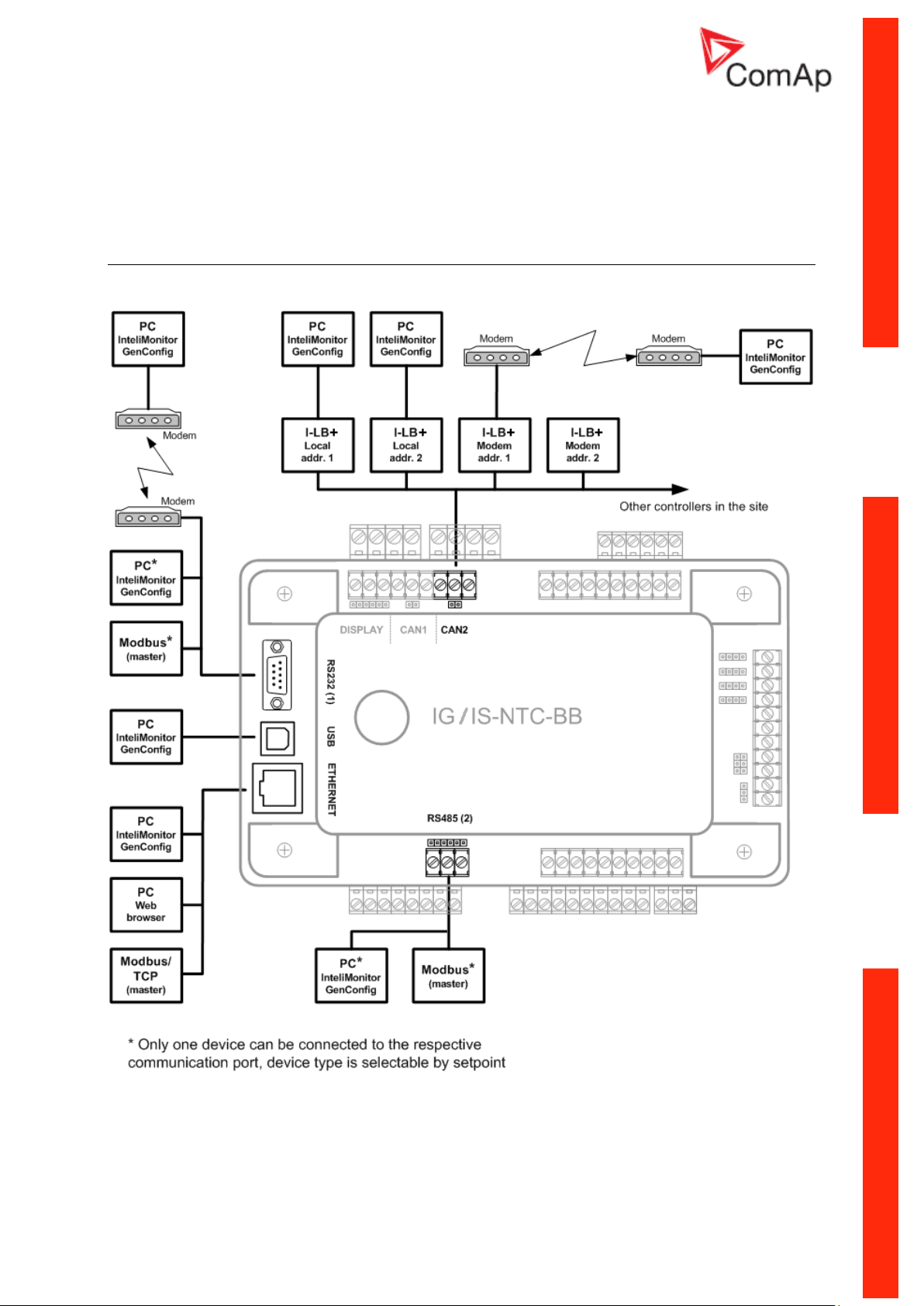
IG/IS/IM-NTC-BB - Communications
Communication Guide, ©ComAp – March 2014 7
IGS-NT Communication Guide 03-2014.pdf
Page 8
IG/IS/IM-NTC-BB - Terminals
Communication Guide, ©ComAp – March 2014 8
IGS-NT Communication Guide 03-2014.pdf
Page 9

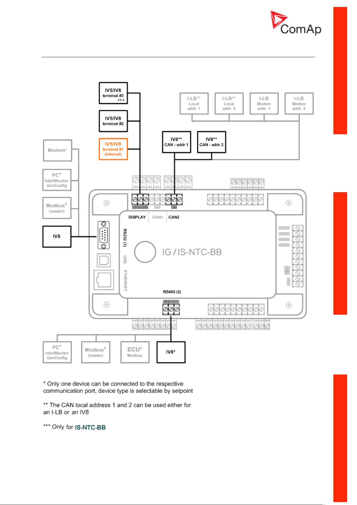
IG/IS/IM-NTC-BB - Peripheral modules
Communication Guide, ©ComAp – March 2014 9
IGS-NT Communication Guide 03-2014.pdf
Page 10
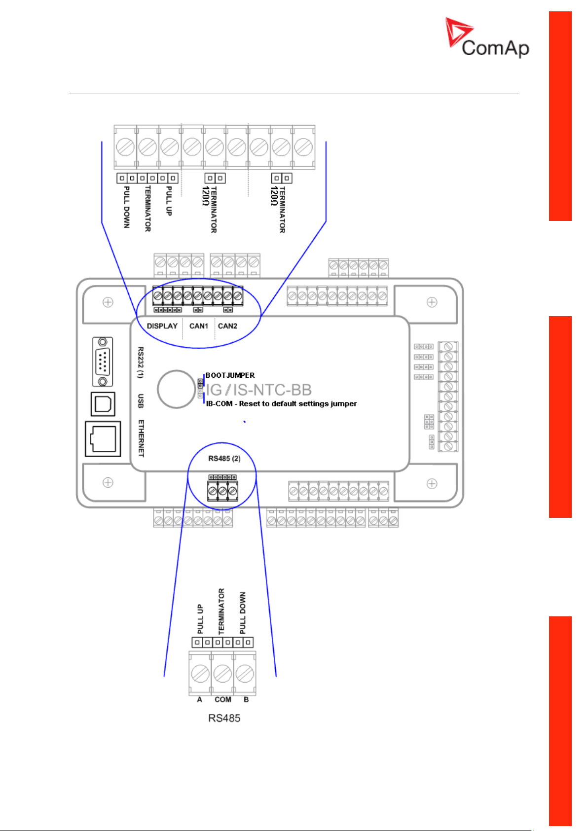
IG/IS/IM-NTC-BB - Jumpers settings
Communication Guide, ©ComAp – March 2014 10
IGS-NT Communication Guide 03-2014.pdf
Page 11
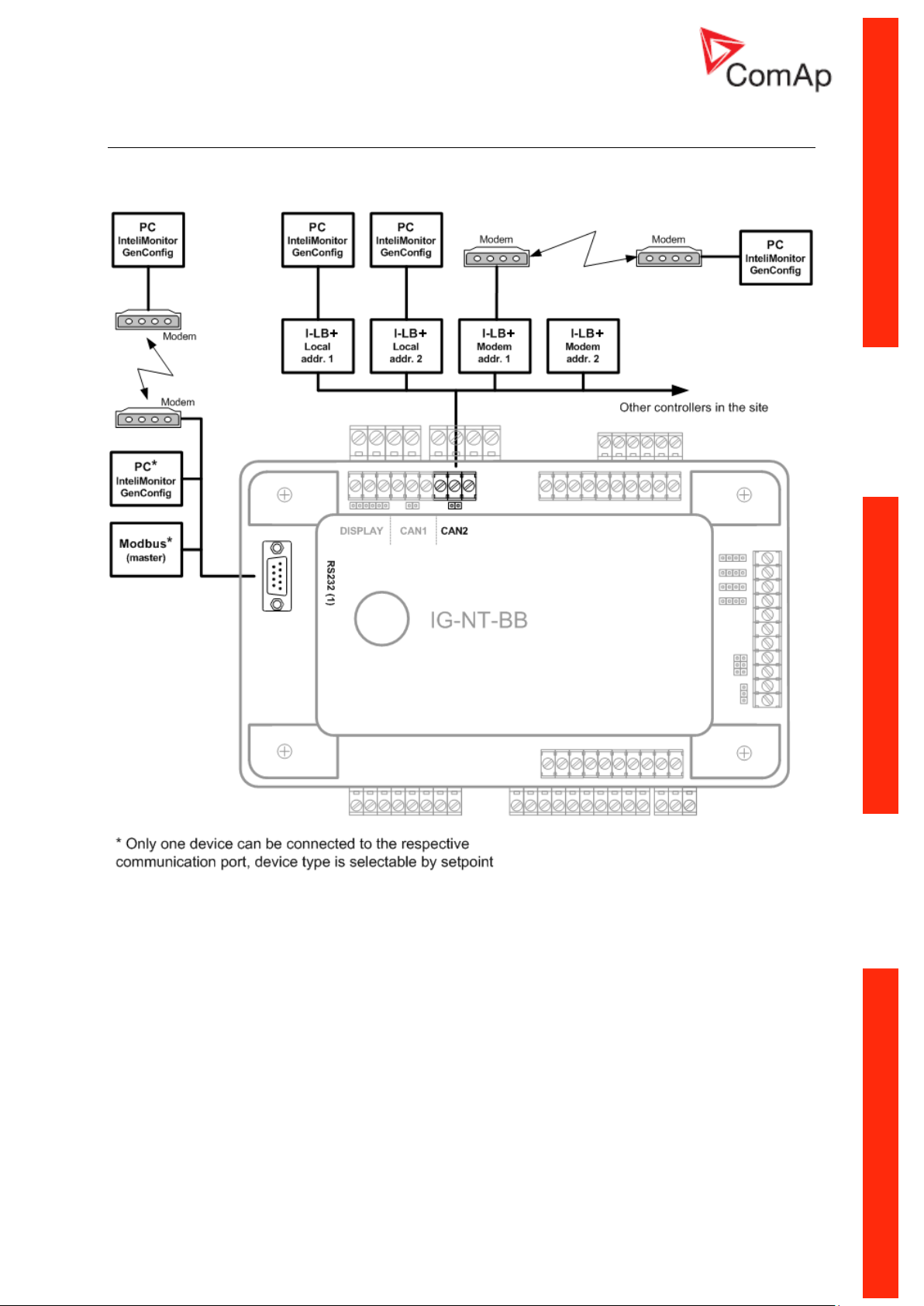
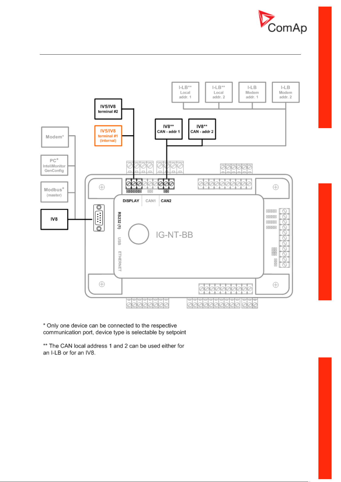
IG/IM-NT-BB - Communication
Communication Guide, ©ComAp – March 2014 11
IGS-NT Communication Guide 03-2014.pdf
Page 12
IG/IM-NT-BB - Terminals
Communication Guide, ©ComAp – March 2014 12
IGS-NT Communication Guide 03-2014.pdf
Page 13
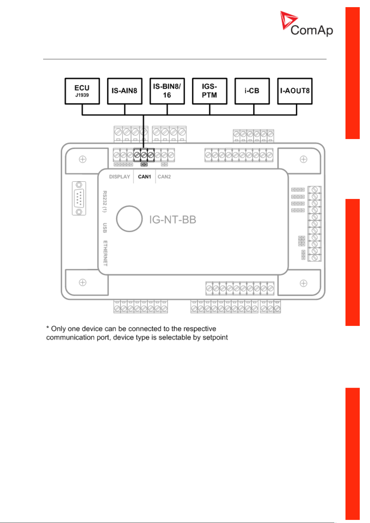
IG/IM-NT-BB - Peripheral modules
Communication Guide, ©ComAp – March 2014 13
IGS-NT Communication Guide 03-2014.pdf
Page 14

IG/IM-NT-BB - Jumpers settings
Communication Guide, ©ComAp – March 2014 14
IGS-NT Communication Guide 03-2014.pdf
Page 15
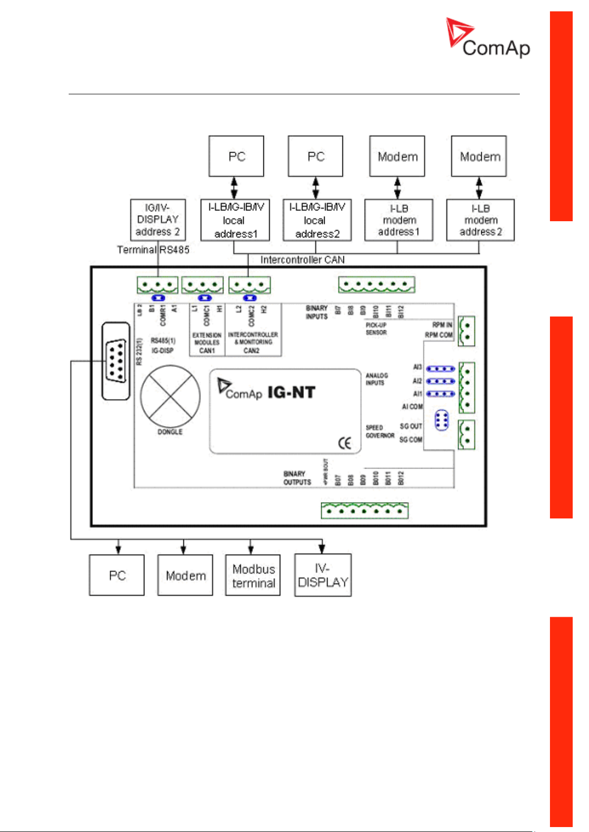
IG-NT - Communications, Terminals
Communication Guide, ©ComAp – March 2014 15
IGS-NT Communication Guide 03-2014.pdf
Page 16
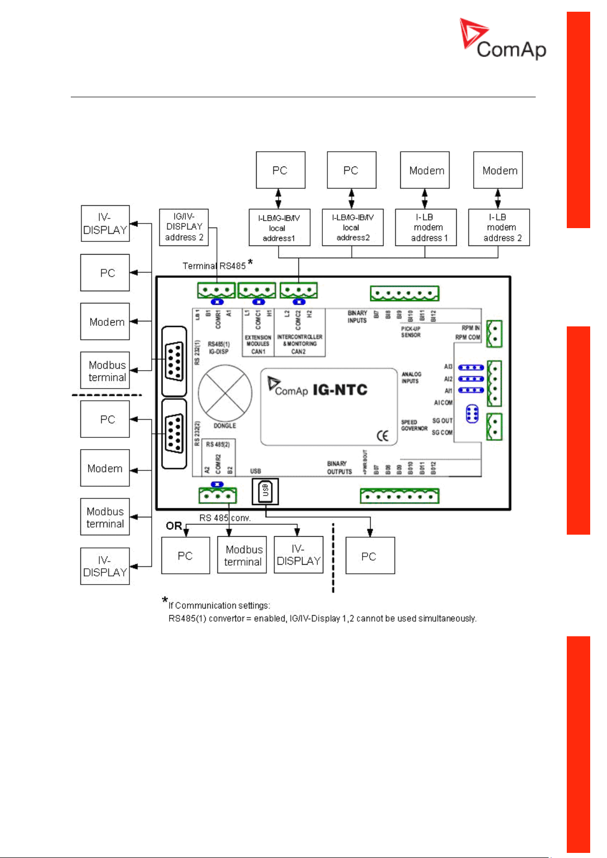
IG-NTC - Communications, Terminals
Communication Guide, ©ComAp – March 2014 16
IGS-NT Communication Guide 03-2014.pdf
Page 17
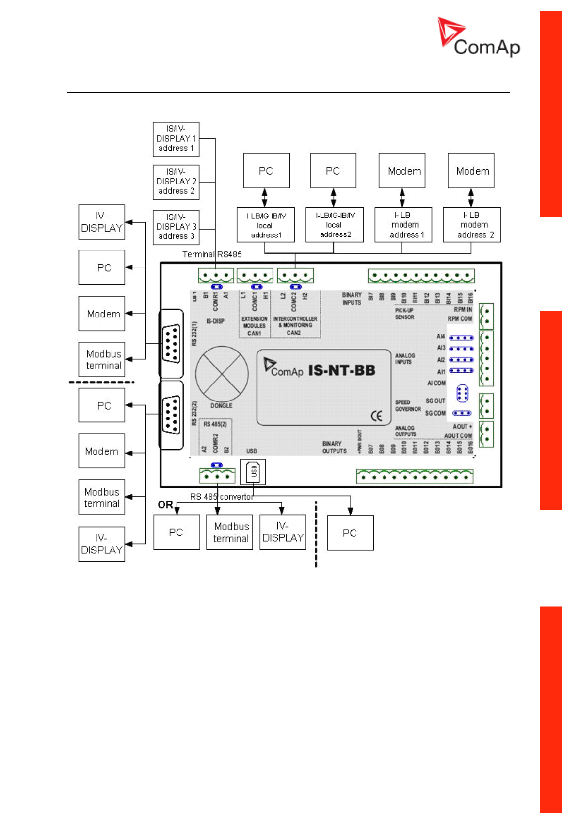
IS-NT-BB - Communications, Terminals
Communication Guide, ©ComAp – March 2014 17
IGS-NT Communication Guide 03-2014.pdf
Page 18
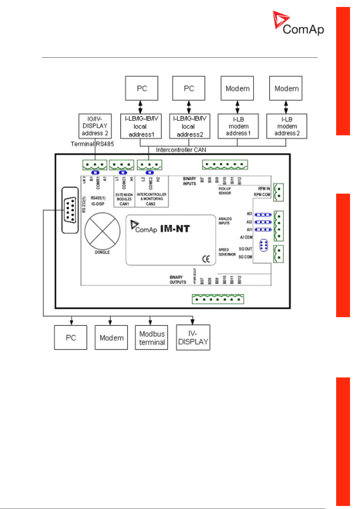
IM-NT - Communications, Terminals
Communication Guide, ©ComAp – March 2014 18
IGS-NT Communication Guide 03-2014.pdf
Page 19
Monitoring Local on site - Comap SW
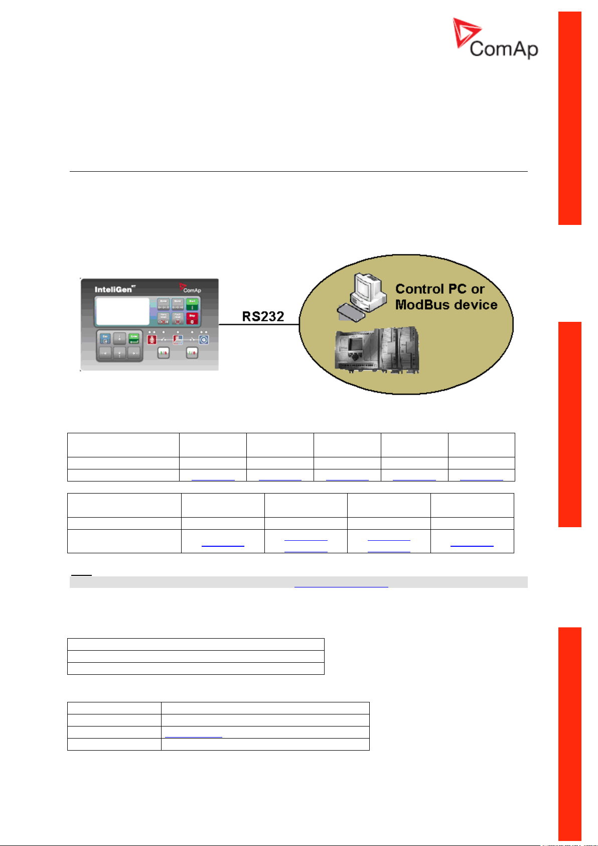
RS232
PC
Controllers
IG-NT-BB
IG-NTC-BB
IS-NTC-BB
IM-NT-BB
IM-NTC-BB
Connection applicable
YES
YES
YES
YES
YES
Available ports
RS232(1)
RS232(1)
RS232(1)
RS232(1)
RS232(1)
Controllers
IG-NT
IG-NTC
IS-NT-BB
IM-NT
Connection applicable
YES
YES
YES
YES
Available ports
RS232(1)
RS232(1)
RS232(2)
RS232(1)
RS232(2)
RS232(1)
RS232(1) mode = DIRECT
RS485(1) conv. = DISABLED
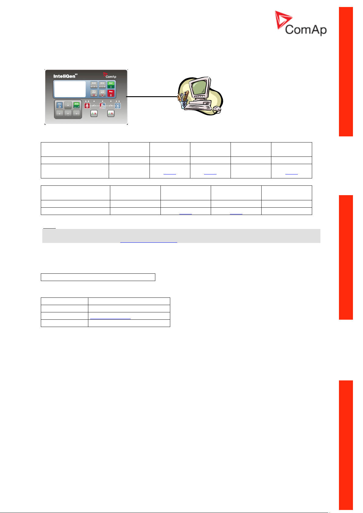
Equipment needed
Controller side
-
Connection
RS232 cable up to 10m
PC side
RS232 connection or RS232/USB converter
Direct PC connection to Single gen-set
RS232 connection
Controllers
Hint:
Other way how to realize RS232 connection is via external bridge I-LB+.
Controller setup
(Setpoints/Comms settings group)
Equipment
Communication Guide, ©ComAp – March 2014 19
IGS-NT Communication Guide 03-2014.pdf
Page 20
USB connection
USB
PC
Controllers
IG-NT-BB
IG-NTC-BB
IS-NTC-BB
IM-NT-BB
IM-NTC-BB
Connection applicable
NO
YES
YES
NO
YES
Available ports
external
bridge
USB
USB
external
bridge
USB
Controllers
IG-NT
IG-NTC
IS-NT-BB
IM-NT
Connection applicable
NO
YES
YES
NO
Available ports
external bridge
USB
USB
external bridge
No special settings are required
Equipment needed
Controller side
-
Connection
USB cable A-B
PC side
USB connection
Controllers
Hint:
Direct USB connection is not possible for some controllers, however USB connection is available for
all mentioned controllers via external bridge I-LB+.
Controller setup
(Setpoints/Comms settings group)
Equipment
Communication Guide, ©ComAp – March 2014 20
IGS-NT Communication Guide 03-2014.pdf
Page 21
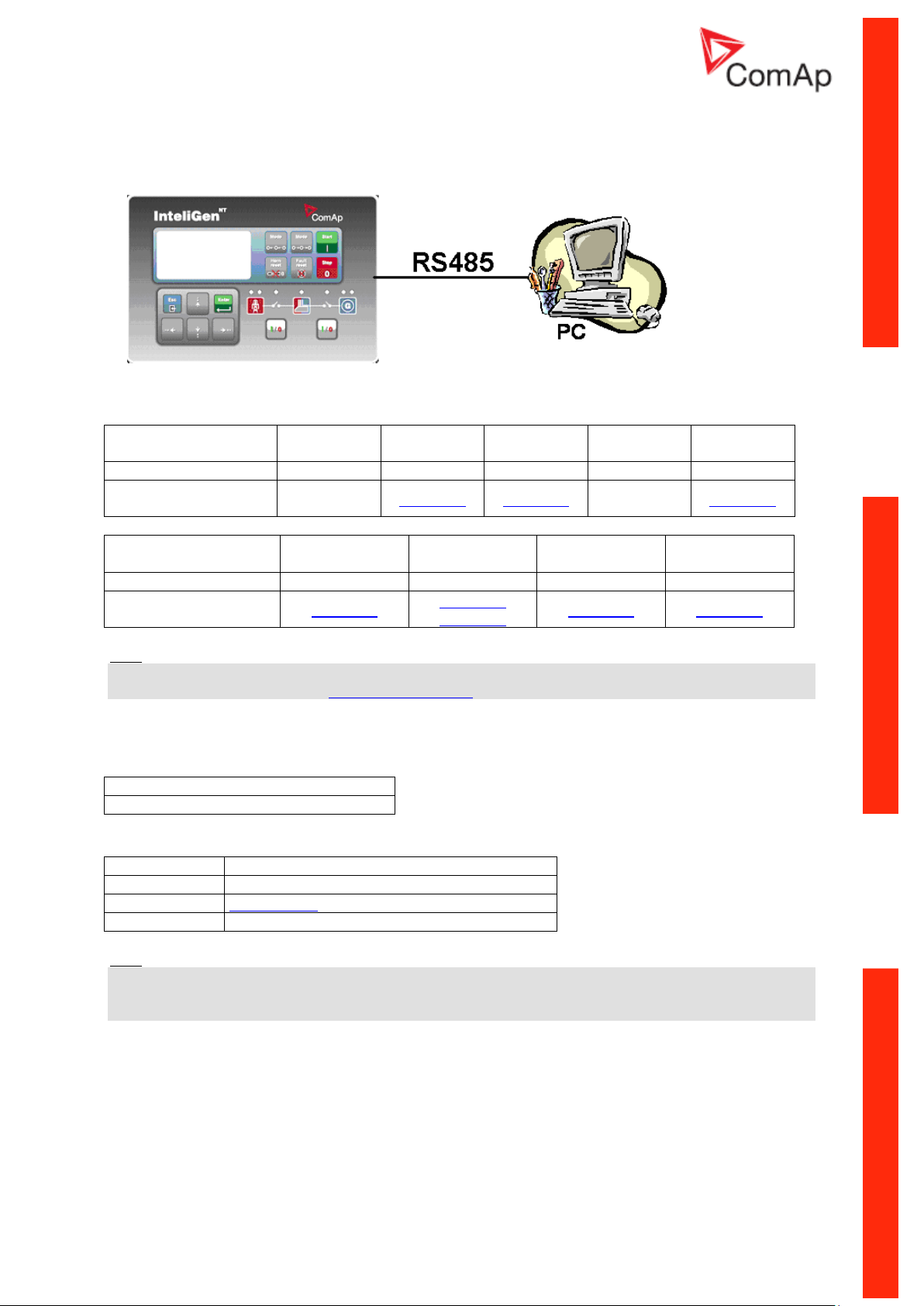
RS485 connection
Controllers
IG-NT-BB
IG-NTC-BB
IS-NTC-BB
IM-NT-BB
IM-NTC-BB
Connection applicable
NO
YES
YES
NO
YES
Available ports
external
bridge
RS485(2)
RS485(2)
external
bridge
RS485(2)
Controllers
IG-NT
IG-NTC
IS-NT-BB
IM-NT
Connection applicable
YES
YES
YES
YES
Available ports
RS485(1)
RS485(1)
RS485(2)
RS485(2)
RS485(1)
RS232(2) mode = DIRECT
RS485(2) conv. = ENABLED
Equipment needed
Controller side
-
Connection
RS485 cable - Twisted pair, length up to 1 km
PC side
Converter RS485/RS232 or USB
Controllers
Hint:
Direct RS485 connection is not possible for some controllers, however RS485 connection is available
for all mentioned controllers via external bridge I-LB+.
Controller setup
(Setpoints/Comms settings group)
Equipment
Hint:
RS485 connection can be used for gen-set control for longer distance. IG-NT-BB has no possibility of
direct connection to RS485 bus. This controller provides RS232 port only. External converter from
RS232 to RS485 is needed.
Communication Guide, ©ComAp – March 2014 21
IGS-NT Communication Guide 03-2014.pdf
Page 22
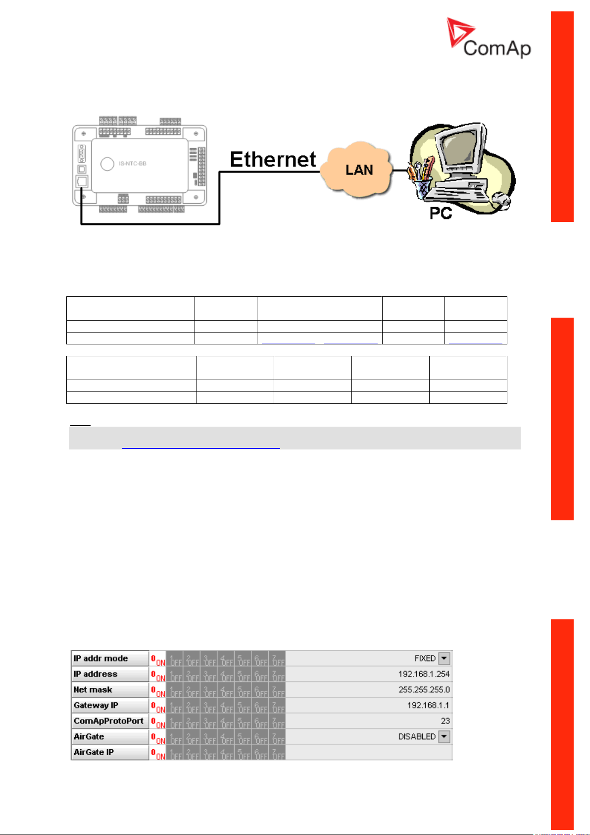
Ethernet connection (Direct)
Controllers
IG-NT-BB
IG-NTC-BB
IS-NTC-BB
IM-NT-BB
IM-NTC-BB
Connection applicable
NO
YES
YES
NO
YES
Available ports or modules
-
ETHERNET
ETHERNET
-
ETHERNET
Controllers
IG-NT
IG-NTC
IS-NT-BB
IM-NT
Connection applicable
NO
NO
NO
NO
Available ports or modules
- - -
-
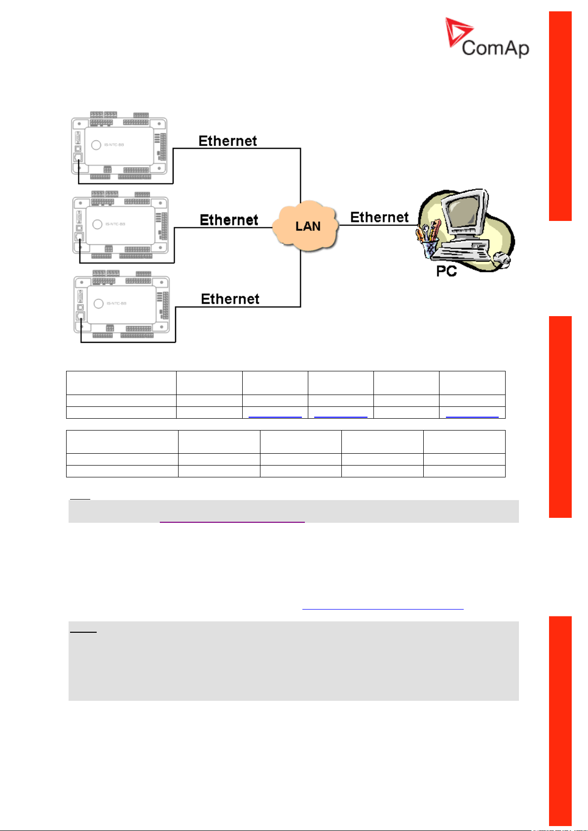
The Internet (Ethernet) connection is a point-to-point connection between a PC and a controller or site
via an TCP/IP protocol-based network. The physical configuration of such network can be a small
local area ethernet network as well as the Internet.
Controllers
Hint:
Ethernet connection is available for all mentioned controllers via external bridge IG-IB or IB-NT (see
the chapter Ethernet connection via IG-IB/IB-NT).
Number of clients connected simultaneously
2 clients with InteliMonitor or WebSupervisor (Comap/TCP protocol)
2 clients with web interface
Using a web browser
Ethernet connection to controller makes possible using any web browser for basic monitoring and
adjustment of the controller. Simply put the IP address of the module into the address line in your web
browser like http://192.168.1.254 and then enter access code. In case of connection from web
browser there is 5 minutes timeout after closing the browser window. After that the client is
automatically logged out.
Ethernet connection settings
Parameters can be set via any type of connection (USB, RS232, Ethernet). Setup is provided via
InteliMonitor. For Ethernet connection set these parameters in Comms Settings group:
Communication Guide, ©ComAp – March 2014 22
IGS-NT Communication Guide 03-2014.pdf
Page 23
NOTE:
Equipment needed
Controller side
-
Connection
Ethernet cable to LAN, for point to point connection
between PC and controller use cross-wired cable
PC side
ETHERNET connection
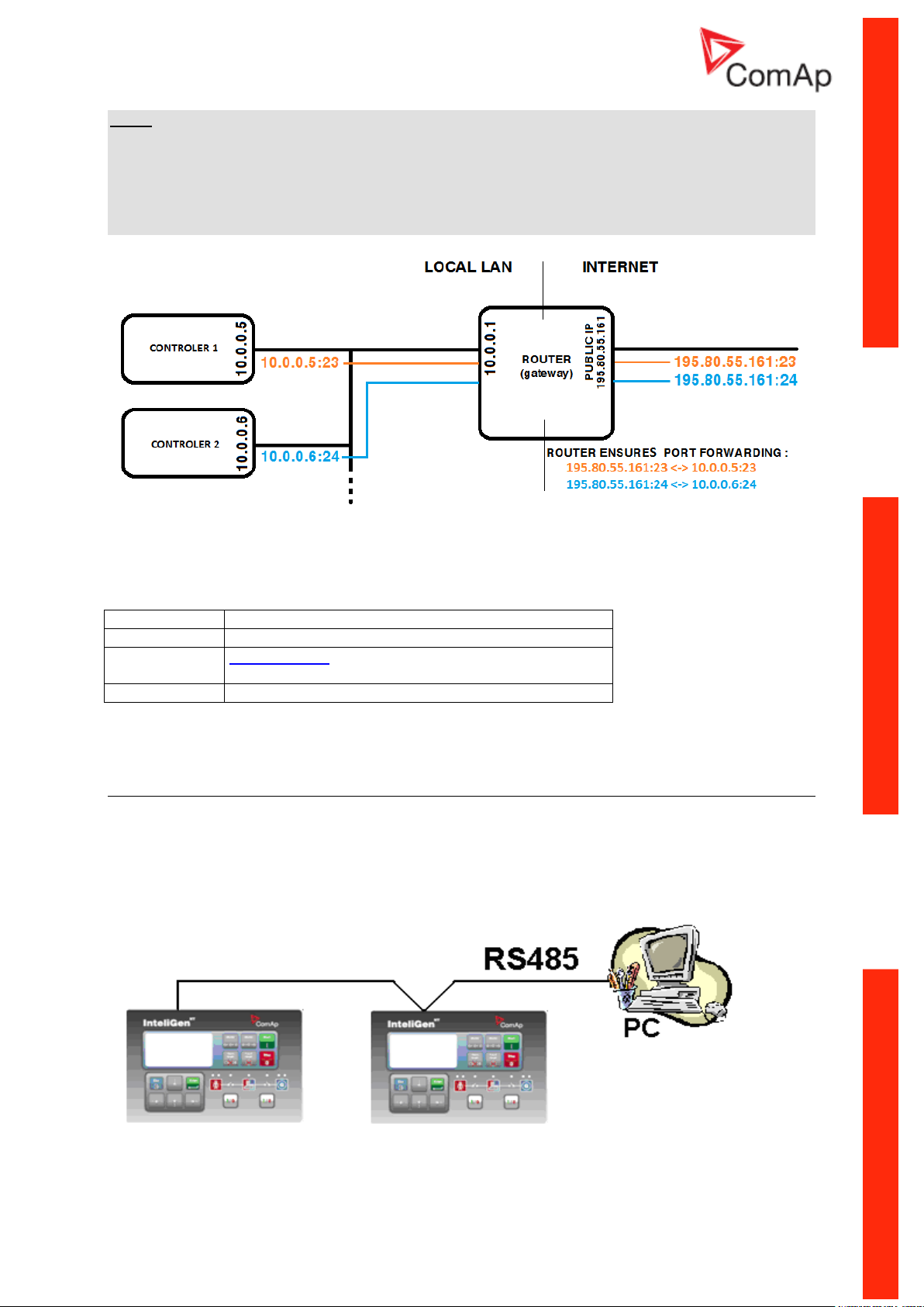
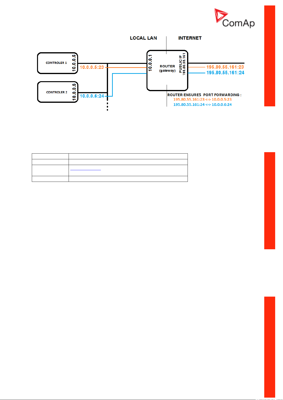
The IP addresses of the controllers must be accessible from the remote computer. If the remote
computer is connected into another LAN segment than the gen-sets are, there must be a gateway(s)
that enable direct traffic between the segments. If the remote computer is connected via Internet, then
the internet gateway of the LAN where gen-sets are connected must have public IP address, must
allow incoming traffic and must provide port forwarding from the external public IP to the different
internal gen-set IPs according to the port used.
INTERNET GATEWAY CONFIGURATION EXAMPLE (PORT FORWARDING)
Equipment
Direct PC connection to Multiple gen-sets
RS485 connection
Communication Guide, ©ComAp – March 2014 23
IGS-NT Communication Guide 03-2014.pdf
Page 24
Controllers
Controllers
IG-NT-BB
IG-NTC-BB
IS-NTC-BB
IM-NT-BB
IM-NTC-BB
Connection applicable
NO
YES
YES
NO
YES
Available ports
-
RS485(2)
RS485(2)
-
RS485(2)
Controllers
IG-NT
IG-NTC
IS-NT-BB
IM-NT
Connection applicable
YES
YES
YES
YES
Available ports
RS485(1)
RS485(1)
RS485(2)
RS485(2)
RS485(1)
RS232(2) mode = DIRECT
RS485(2) conv. = ENABLED
Equipment needed
Controller side
-
Connection
RS485 cable - Twisted pair, length up to 1 km
PC side
RS232 connection, Converter RS485/RS232
HW/SW control
No matter
Controller setup
(Setpoints/Comms settings group)
Hint:
IG-NT-BB has no possibility of direct connection to RS485 bus. This controller provides RS232 port
only. External converter from RS232 to RS485 is needed.
Equipment
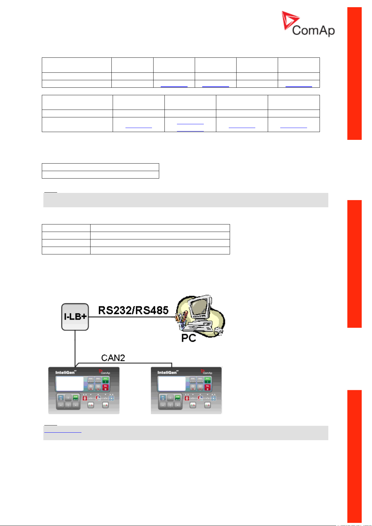
RS232/485 connection (I-LB+)
Hint:
I-LB+ module enables monitoring and configuration up to 32 controllers interconnected via CAN(2)
intercontroller bus. It is also possible to use I-LB+ for single controller connection.
I-LB+ hardware setup
(all jumpers in those positions)
Communication Guide, ©ComAp – March 2014 24
IGS-NT Communication Guide 03-2014.pdf
Page 25
ComAp/ModBus
Open
ADDR1/ADDR2
Selection of CAN address. Open = ADDR1, Close = ADDR2
It is possible to use up to two I-LB+ devices in direct mode on CAN(2)
bus. Let jumper open in case of using one I-LB+ module. Other I-LB
module has to have this jumper closed. (read more about I-LB+ module)
DIRECT/MODEM
Open
RS485/RS232
Selection of communication port (jumper is in RS232 or RS485 position)
Comm. speed.
No matter
RS485 120 Ohm
Open = terminator not connected, Close = terminator connected
CAN 120 Ohm
Open = terminator not connected, Close = terminator connected
USB DISABLED/ENABLED
Open
Controllers
Controllers
IG-NT-BB
IG-NTC-BB
IS-NTC-BB
IM-NT-BB
IM-NTC-BB
Connection applicable
YES
YES
YES
YES
YES
Available ports
RS232 on I-
LB+
RS485 on I-
LB+
RS232 on I-
LB+
RS485 on I-
LB+
RS232 on I-
LB+
RS485 on I-
LB+
RS232 on I-
LB+
RS485 on I-
LB+
RS232 on I-
LB+
RS485 on I-
LB+
Controllers
IG-NT
IG-NTC
IS-NT-BB
IM-NT
Connection applicable
YES
YES
YES
YES
Available ports
RS232 on I-LB+
RS485 on I-LB+
RS232 on I-LB+
RS485 on I-LB+
RS232 on I-LB+
RS485 on I-LB+
RS232 on I-LB+
RS485 on I-LB+
Equipment needed
Controller side
I-LB+ unit
Connection
RS232 or RS485 cable
PC side
RS232 connection or RS232/USB converter
RS485 connection or RS485/USB converter
Equipment
Communication Guide, ©ComAp – March 2014 25
IGS-NT Communication Guide 03-2014.pdf
Page 26
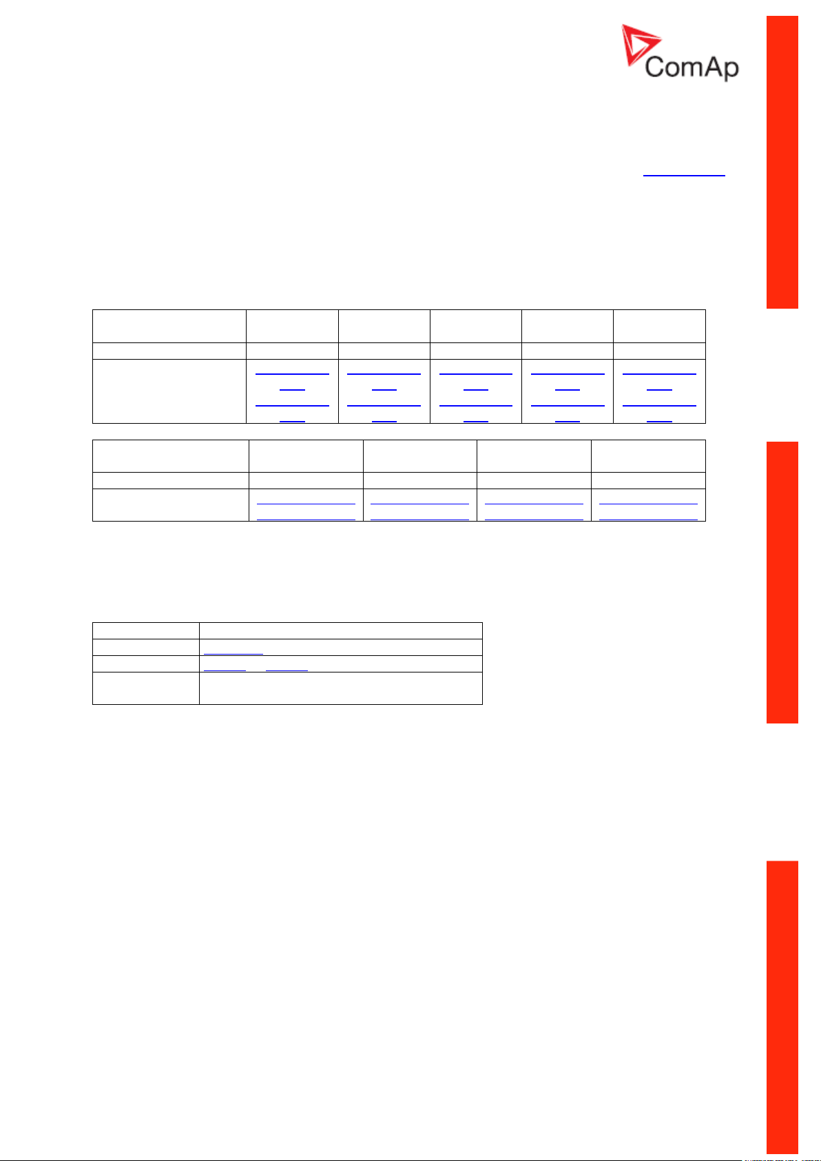
USB connection via I-LB+ module
HW/SW control
no matter (Open)
ComAp/ModBus
Open
ADDR1/ADDR2
Selection of CAN address. Open = ADDR2, Close = ADDR1
(read more about I-LB+ module)
DIRECT/MODEM
Open
RS485/RS232
No matter
Comm. speed.
No matter
RS485 120 Ohm
Open = terminator not connected, Close = terminator connected
CAN 120 Ohm
Open = terminator not connected, Close = terminator connected
USB DISABLED/ENABLED
Close = USB is enabled
Controllers
IG-NT-BB
IG-NTC-BB
IS-NTC-BB
IM-NT-BB
IM-NTC-BB
Connection applicable
YES
YES
YES
YES
YES
Available ports
USB on I-LB+
USB on I-LB+
USB on I-LB+
USB on I-LB+
USB on I-LB+
Controllers
IG-NT
IG-NTC
IS-NT-BB
IM-NT
Connection applicable
YES
YES
YES
YES
Available ports
USB on I-LB+
USB on I-LB+
USB on I-LB+
USB on I-LB+
Equipment needed
Controller side
I-LB+ unit
Connection
USB
PC side
USB connection
Hint:
I-LB+ module enables monitoring and configuration up to 32 controllers interconnected via CAN(2)
intercontroller bus. It is also possible to use I-LB+ for single controller connection.
I-LB+ hardware setup
(all jumpers in those positions)
Controllers
Equipment
Communication Guide, ©ComAp – March 2014 26
IGS-NT Communication Guide 03-2014.pdf
Page 27
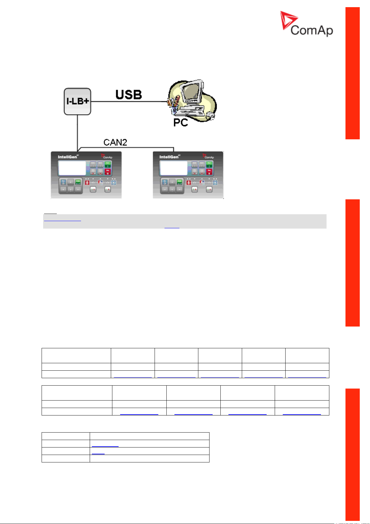
Ethernet connection via IB-NT (IG-IB)
Controllers
IG-NT-BB
IG-NTC-BB
IS-NTC-BB
IM-NT-BB
IM-NTC-BB
Connection applicable
YES
YES
YES
YES
YES
Available ports / modules
IG-IB/IB-NT
IG-IB/IB-NT
IG-IB/IB-NT
IG-IB/IB-NT
IG-IB/IB-NT
Controllers
IG-NT
IG-NTC
IS-NT-BB
IM-NT
Connection applicable
YES
YES
YES
YES
Available ports / modules
IG-IB/IB-NT
IG-IB/IB-NT
IG-IB/IB-NT
IG-IB/IB-NT
Up to 32 controllers can be monitored via one IB-NT (IG-IB). Response time of a system with this type
of connection depends on number of controllers, higher number of controllers means slower system
response time.
Controllers
NOTE:
Max. 3 clients of ComAp type (InteliDDE server, WinScope, WebSupervisor) can be connected
simultaneously to the IB-NT (IG-IB).
Hint:
Get more information about IG-IB internet bridge. For more information about IB-NT internet bridge
read IB-NT-2.0-Reference Guide.pdf.
Communication Guide, ©ComAp – March 2014 27
IGS-NT Communication Guide 03-2014.pdf
Page 28
Ethernet connection (Direct)
Controllers
IG-NT-BB
IG-NTC-BB
IS-NTC-BB
IM-NT-BB
IM-NTC-BB
Connection applicable
NO
YES
YES
NO
YES
Available ports
-
ETHERNET
ETHERNET
-
ETHERNET
Controllers
IG-NT
IG-NTC
IS-NT-BB
IM-NT
Connection applicable
NO
NO
NO
NO
Available ports
- - -
-
Controllers
Hint:
Ethernet connection is available for all mentioned controllers via external internet bridge IG-IB or IBNT (see the chapter Ethernet connection IG-IB/IB-NT).
Number of clients connected simultaneously
2 clients with InteliMonitor or WebSupervisor (Comap/TCP protocol)
2 clients with web interface
Ethernet connection settings
Perform the connection settings the same way as for Single controller Ethernet connection.
NOTE:
The IP addresses of the controllers must be accessible from the remote computer. If the remote
computer is connected into another LAN segment than the gen-sets are, there must be a gateway(s)
that enable direct traffic between the segments. If the remote computer is connected via Internet, then
the internet gateway of the LAN where gen-sets are connected must have public IP address, must
allow incoming traffic and must provide port forwarding from the external public IP to the different
internal gen-set IPs according to the port used.
Communication Guide, ©ComAp – March 2014 28
IGS-NT Communication Guide 03-2014.pdf
Page 29
Equipment needed
Controller side
-
Connection
Ethernet cable to LAN, for point to point connection
between PC and controller use cross-wired cable
PC side
ETHERNET connection
INTERNET GATEWAY CONFIGURATION EXAMPLE (PORT FORWARDING)
Equipment
Communication Guide, ©ComAp – March 2014 29
IGS-NT Communication Guide 03-2014.pdf
Page 30
Monitoring Local on site - MODBUS
Controllers
IG-NT-BB
IG-NTC-BB
IS-NTC-BB
IM-NT-BB
IM-NTC-BB
Connection applicable
YES
YES
YES
YES
YES
Available ports
RS232(1)
RS232(1)
RS232(1)
RS232(1)
RS232(1)
Controllers
IG-NT
IG-NTC
IS-NT-BB
IM-NT
Connection applicable
YES
YES
YES
YES
Available ports
RS232(1)
RS232(1)
RS232(2)
RS232(1)
RS232(2)
RS232(1)
RS232(1 or 2) mode = MODBUS-DIRECT
RS485(1 or 2) conv. = DISABLED
RS232(1)MBCSpd = 9600, 19200, 38400, 57600
Equipment needed
Controller side
-
Connection
RS232 cable up to 10 m
Other device side
RS232 connection or RS232/USB converter
ModBus - Single gen-set
RS232 ModBus
Controllers
Hint:
Other way how to realize RS232 connection is via external bridge I-LB+.
Controller setup
(Setpoints/Comms settings group)
Equipment
Communication Guide, ©ComAp – March 2014 30
IGS-NT Communication Guide 03-2014.pdf
Page 31

RS485 ModBus
Controllers
IG-NT-BB
IG-NTC-BB
IS-NTC-BB
IM-NT-BB
IM-NTC-BB
Connection applicable
NO
YES
YES
NO
YES
Available ports
-
RS485(2)
RS485(2)
-
RS485(2)
Controllers
IG-NT
IG-NTC
IS-NT-BB
IM-NT
Connection applicable
YES
YES
YES
YES
Available ports
RS485(1)
RS485(1)
RS485(2)
RS485(2)
RS485(1)
RS232(2) mode = MODBUS-DIRECT
RS485(2) conv. = ENABLED
RS232(2)MBCSpd = 9600, 19200, 38400, 57600
Equipment needed
Controller side
-
Connection
RS485 cable
Other device side
RS485 connection or RS485/USB converter
Controllers
Hint:
Some controllers do not allowe direct RS485 connection, however RS485 connection is available for
all mentioned controllers via external bridge I-LB+.
Controller setup
(Setpoints/Comms settings group)
Equipment
Communication Guide, ©ComAp – March 2014 31
IGS-NT Communication Guide 03-2014.pdf
Page 32

Ethernet - MODBUS/TCP (Direct)
Controllers
IG-NT-BB
IG-NTC-BB
IS-NTC-BB
IM-NT-BB
IM-NTC-BB
Connection applicable
NO
YES
YES
NO
YES
Available ports
-
ETHERNET
ETHERNET
-
ETHERNET
Controllers
IG-NT
IG-NTC
IS-NT-BB
IM-NT
Connection applicable
NO
NO
NO
NO
Available ports
- - -
-
Controllers
Hint:
Ethernet Modbus/TCP connection is available for all mentioned controllers via external internet bridge
IB-NT (see the chapter Ethernet – MODBUS (IB-NT)).
Number of clients connected simultaneously
1 client ModBus TCP/IP
Ethernet connection settings
Perform the connection settings the same way as for Single controller Ethernet connection.
Modbus/TCP access code
Every Modbus/TCP session has to be started with writing the access code from the modbus/tcp client
to the controller. If the session is closed and reopened again the access code must be written again.
The session can be closed by the client or the controller closes the session automatically if there is no
activity from the client side for 15s.
- There are new dedicated registers for entering the AccessCode via Modbus/TCP.
- The register numbers are 46339-46346 (register address 6338-6345).
- The previous method using register address 24535 remains working as well.
- Example of the Modbus message is following (in HEX):
01 10 18 C2 00 08 10 30 00 00 00 00 00 00 00 00 00 00 00 00 00 00 00 FE F3
01 Controller address
10 Modbus function (16dec – Write multiple registers)
18C2 Register address (18C2hex = 6338dec = register 46339)
0008 Number of registers
10 Length of the data (Number of registers x 2B)
30000000... Access code string (16 chars, null-terminated, ASCII, here “0”)
FEF3 CRC
Communication Guide, ©ComAp – March 2014 32
IGS-NT Communication Guide 03-2014.pdf
Page 33

Some devices do not support the modbus function 16. In this case can be the access code
Equipment needed
Controller side
-
Connection
Ethernet cable to LAN, for point to point connection
between PC and controller use cross-wired cable
PC side
ETHERNET connection
Controllers
IG-NT-BB
IG-NTC-BB
IS-NTC-BB
IM-NT-BB
IM-NTC-BB
Connection applicable
NO
YES
YES
NO
YES
Available ports
-
RS485(2)
RS485(2)
-
RS485(2)
Controllers
IG-NT
IG-NTC
IS-NT-BB
IM-NT
Connection applicable
NO
YES
YES
NO
Available ports
RS485(1)
RS485(1)
RS485(2)
RS485(2)
-
RS232(2) mode = MODBUS-DIRECT
RS485(2) conv. = ENABLED
RS232(2)MBCSpd = 9600, 19200, 38400, 57600
writen in controller as one register No. 46339 using the function 6. The access code has to
be the number in the range 0 to 65535.
Equipment
For more informations about ModBus implementation to ComAp controllers read the chapter ModBus
communication.
ModBus - Multiple gen-sets
RS485 – MODBUS
Controllers
Controller setup
(Setpoints/Comms settings group)
Communication Guide, ©ComAp – March 2014 33
IGS-NT Communication Guide 03-2014.pdf
Page 34

Hint:
Equipment needed
Controller side
-
Connection
RS485 cable - Twisted pair, length up to 1 km
Other device side
RS485 connection or RS485/RS232 or USB converter
HW/SW control
No matter
ComAp/ModBus
Close
ADDR1/ADDR2
Selection of CAN address. Open = ADDR1, Close = ADDR2
It is possible to use up to two I-LB+ devices in direct mode on CAN(2)
bus. Let jumper open in case of using one I-LB+ module. Other I-LB
module has to have this jumper closed. (read more about I-LB+ module)
DIRECT/MODEM
No matter
RS485/RS232
Selection of communication port (jumper is in RS232 or RS485 position)
Comm. speed.
Selection of communication speed by jumpers P13, P14 to 9600, 19200,
38400, 57600 bps
RS485 120 Ohm
Open = terminator not connected, Close = terminator connected
CAN 120 Ohm
Open = terminator not connected, Close = terminator connected
USB DISABLED/ENABLED
No matter
Controllers
IG-NT-BB
IG-NTC-BB
IS-NTC-BB
IM-NT-BB
IM-NTC-BB
Connection
applicable
YES
YES
YES
YES
YES
Available
ports
RS232 on I-LB+
RS485 on I-LB+
RS232 on I-LB+
RS485 on I-LB+
RS232 on I-LB+
RS485 on I-LB+
RS232 on I-LB+
RS485 on I-LB+
RS232 on I-LB+
RS485 on I-LB+
For gen-set control for longer distance can be RS485 used. IG-NT-BB has no possibility of direct
connection to RS485 bus. This controller provides RS232 port only. External converter from RS232 to
RS485 may be a good solution (for example...ADAM).
Equipment
RS232/RS485 – MODBUS (I-LB+)
Hint:
I-LB+ module enables monitoring and configuration up to 32 controllers interconnected via CAN(2)
intercontroller bus. It is also possible to use I-LB+ for single controller connection.
I-LB+ hardware setup
(all jumpers in those positions)
Controllers
Communication Guide, ©ComAp – March 2014 34
IGS-NT Communication Guide 03-2014.pdf
Page 35

Controllers
IG-NT
IG-NTC
IS-NT-BB
IM-NT
Connection applicable
NO
YES
YES
NO
Available ports
RS232 on I-LB+
RS485 on I-LB+
RS232 on I-LB+
RS485 on I-LB+
RS232 on I-LB+
RS485 on I-LB+
RS232 on I-LB+
RS485 on I-LB+
Equipment
Equipment needed
Controller side
I-LB+ unit
Connection
RS232, RS485 cable
PC side
RS232 connection or RS232/USB converter
RS485 connection or RS485/USB converter
Controllers
IG-NT-BB
IG-NTC-BB
IS-NTC-BB
IM-NT-BB
IM-NTC-BB
Connection applicable
YES
YES
YES
YES
YES
Available ports / modules
external
bridge IB-NT
external
bridge IB-NT
external
bridge IB-NT
external
bridge IB-NT
external
bridge IB-NT
Controllers
IG-NT
IG-NTC
IS-NT-BB
IM-NT
Connection applicable
YES
YES
YES
YES
Available ports / modules
external bridge
IB-NT
external bridge
IB-NT
external bridge
IB-NT
external bridge
IB-NT
Ethernet - MODBUS (IB-NT)
Up to 32 controllers can be monitored via one IG-IB. Response time of a system with this type of
connection depends on number of controllers, higher number of controllers means slower system
response time.
Controllers
Hint:
For more information about IB-NT internet bridge read IB-NT-2.0-Reference Guide.pdf.
Communication Guide, ©ComAp – March 2014 35
IGS-NT Communication Guide 03-2014.pdf
Page 36

Ethernet - MODBUS/TCP (Direct)
Controllers
IG-NT-BB
IG-NTC-BB
IS-NTC-BB
IM-NT-BB
IM-NTC-BB
Connection applicable
NO
YES
YES
NO
YES
Available ports
-
ETHERNET
ETHERNET
-
ETHERNET
Controllers
IG-NT
IG-NTC
IS-NT-BB
IM-NT
Connection applicable
NO
NO
NO
NO
Available ports
- - -
-
Equipment needed
Controller side
-
Connection
Ethernet cable to LAN, for point to point connection
between PC and controller use cross-wired cable
PC side
ETHERNET connection
Controllers
Hint:
Ethernet Modbus/TCP connection is available for all mentioned controllers via external internet bridge
IB-NT (see the chapter Ethernet – MODBUS (IB-NT)).
Number of clients connected simultaneously
1client ModBus TCP/IP
Ethernet connection settings
Perform the connection settings the same way as for Single controller Ethernet connection.
Equipment
For more informations about ModBus implementation to ComAp controllers read the chapter ModBus
communication.
Communication Guide, ©ComAp – March 2014 36
IGS-NT Communication Guide 03-2014.pdf
Page 37

Remote monitoring
Controllers
IG-NT-BB
IG-NTC-BB
IS-NTC-BB
IM-NT-BB
IM-NTC-BB
Connection applicable
NO
YES
YES
NO
YES
Available ports
-
ETHERNET
ETHERNET
-
ETHERNET
Controllers
IG-NT
IG-NTC
IS-NT-BB
IM-NT
Connection applicable
NO
NO
NO
NO
Available ports
- - -
-
Connection to Internet (Direct)
Controllers
Hint:
Internet connection is available for all mentioned controllers via external bridge IG-IB or IB-NT (see the
chapter Ethernet connection via IG-IB/IB-NT).
Number of clients connected simultaneously
2 clients with InteliMonitor or WebSupervisor (Comap/TCP protocol)
1 client Modbus/TCP
2 clients with web interface
Communication Guide, ©ComAp – March 2014 37
IGS-NT Communication Guide 03-2014.pdf
Page 38

Ethernet connection settings
Equipment needed
Controller side
-
Connection
Ethernet cable to LAN, for point to point connection
between PC and controller use cross-wired cable
PC side
ETHERNET connection
Software
GenConfig
InteliMonitor
WinScope
Applicable
YES
YES
YES
Perform the connection settings the same way as for Single controller Ethernet connection.
How to open Internet connection in InteliMonitor?
Use the same procedure as well as for Multiple gen-sets Ethernet connection.
Using a web browser
Ethernet connection to controller makes possible using any web browser for basic monitoring and
adjustment of the controller. Simply put the IP address of the module into the address line in your web
browser like http://192.168.1.254 and then enter access code. In case of connection from web
browser there is 5 minutes timeout after closing the browser window. After that the client is
automatically logged out.
NOTE:
The IP addresses of the controllers must be accessible from the remote computer. If the remote
computer is connected into another LAN segment than the gen-sets are, there must be a gateway(s)
that enable direct traffic between the segments. If the remote computer is connected via Internet, then
the internet gateway of the LAN where gen-sets are connected must have public IP address, must
allow incoming traffic and must provide port forwarding from the external public IP to the different
internal gen-set IPs according to the port used.
INTERNET GATEWAY CONFIGURATION EXAMPLE (PORT FORWARDING)
Equipment
Available software for IG/IS-NT
Communication Guide, ©ComAp – March 2014 38
IGS-NT Communication Guide 03-2014.pdf
Page 39

Internet connection via AirGate
This connection type is used for connection to controllers/sites, that are connected to the Internet,
however they do not have public and static IP address. The controllers connect by themselves to the
AirGate server and cyclically ask whether there is a connection request from a client or not. On the
other side the clients (InteliMonitor, WebSupervisor) connect to the AirGate server instead of
connecting directly to the controller. The server then creates a "tunnel" between the client and the
controller. Internet connection via AirGate server is supported by controllers IG-NTC-BB and IS-NTCBB with ethernet connection possibility. The connection to ethernet is realized the same way as
remote ethernet connection.
CAUTION!
To avoid unauthorized access to the controller change the access code and keep it secret!
PRINCIPLE OF AIRGATE CONNECTION
Airgate connection settings
Parameters can be set via any type of connection (USB, RS232, Ethernet). Setup is provided via
InteliMonitor. For ethernet connection set these parameters in Comms Settings group:
Communication Guide, ©ComAp – March 2014 39
IGS-NT Communication Guide 03-2014.pdf
Page 40

Controllers
Controllers
IG-NT-BB
IG-NTC-BB
IS-NTC-BB
IM-NT-BB
IM-NTC-BB
Connection applicable
NO
YES
YES
NO
YES
Available ports
external
bridge IB-NT
ETHERNET
ETHERNET
external
bridge IB-NT
ETHERNET
Controllers
IG-NT
IG-NTC
IS-NT-BB
IM-NT
Connection applicable
NO
NO
NO
NO
Available ports
external bridge
IB-NT
external bridge
IB-NT
external bridge
IB-NT
external bridge
IB-NT
CAUTION!
Connection via AirGate is supported by controllers with direct connection to LAN only or via IB-NT
module. Airgate connection is not available for connection via IG-IB module.
Connection to InteliMonitor via AirGate server
1. Select the AirGate connection type.
2. Fill-in the correct AirGate ID for each controller.
3. Enter the AirGate server address.
Hint:
You will obtain the AirGate ID by the registration of the particular controller on the AirGate server. Set
all setpoints in Comms Settings group according to AirGate connecgtion settings and connect
controller to LAN. Controller AirGate ID will be viewed on the screen.
NOTE:
This function is available in InteliMonitor ver. 2.6 and higher. Please watch the ComAp web site for
detailed information.
NOTE:
Although the controllers in your site are not connected together by the CAN2 bus they must have
different controller addresses.
Communication Guide, ©ComAp – March 2014 40
IGS-NT Communication Guide 03-2014.pdf
Page 41

Controllers
IG-NT-BB
IG-NTC-BB
IS-NTC-BB
IM-NT-BB
IM-NTC-BB
Connection applicable
YES
YES
YES
YES
YES
Available ports
external
bridge IB-NT
ETHERNET
ETHERNET
external
bridge IB-NT
ETHERNET
Controllers
IG-NT
IG-NTC
IS-NT-BB
IM-NT
Connection applicable
YES
YES
YES
YES
Available ports
external bridge
IB-NT
ETHERNET
ETHERNET
external bridge
IB-NT
AIRGATE CONNECTION SETTINGS
WebSupervisor
WebSupervisor is web based system designed for monitoring and controlling ComAp controllers via
the internet. This system offers a number of beneficial features that help optimize revenue for
machinery fleets, as each piece of equipment can be individually monitored for all important operation
values.
Controllers
Communication Guide, ©ComAp – March 2014 41
IGS-NT Communication Guide 03-2014.pdf
Page 42

WebSupervisor connection settings
Connect ComAp
Controller with
WebSupervisor support
to the Internet
Use connection via
AirGate or IG-IB
external bridge
Is connection o.k.? Try
it with InteliMonitor or
LiteEdit or DriveMonitor
Open Internet Browser
http://websupervisor.comap.cz
Login into
WebSupervisor with
your account
Do not have an account?
See chapter How to
Register (Become a User
of the WebSupervisor) and
Login?
Register new Unit into
WebSupervisor. See
chapter Chyba!
Nenalezen zdroj odkazů.
Start to using
WebSupervisor in
accordance with
WebSupervisor manual
Connection of controllers with direct Ethernet port can be realized two diferent ways:
1. Internet connection via AirGate: No fixed and public IP address is needed. Connect
and set the controller the same way as for Internet connection via AirGate.
2. Internet connection without AirgGate: Controller has to have fixed and public IP
address. Connect and set the controller the same way as for Ethernet Connection
(Direct).
Connection of all controllers can be realized using IG-IB external bridge. Connect and set the
controller the same way as for Ethernet (Internet) connection via IG-IB module.
First Steps
Communication Guide, ©ComAp – March 2014 42
IGS-NT Communication Guide 03-2014.pdf
Page 43

Start to using
How to Register (Become a User of the WebSupervisor) and Login?
You can start using WebSupervisor without installation any special software on your PC.
To start and login into WebSupervisor:
1. Open http://websupervisor.comap.cz/ in your browser.
The WebSupervisor homepage appears:
2. Insert your login name and password into field LOGIN NAME and PASSWORD, see below.
If you have not created an access, please send email to
admin.websupervisor@comap.cz. Please send us Name, Login name, Email address
and Timezone. We will create free account for you to start using it.
More information about WebSupervisor you can get in WebSupervisor-2_0 Reference Guide.pdf.
Communication Guide, ©ComAp – March 2014 43
IGS-NT Communication Guide 03-2014.pdf
Page 44

Web interface
The web interface is intended to monitor the controller from a web browser. Static IP address is
required for this function as you must know the IP address to put it into the browser. Public IP address
or port forwarding is required if you want to see the web pages from the Internet.
PORT FORWARDING EXAMPLE FOR WEB CONNECTION
The web server is designed for basic monitoring and adjustment of the controller using a web browser.
Put the Controller IP address into the browser. You will be asked for the controller access code prior
to entering the controller web.
NOTE:
The web server is optimized for IE6 or higher and screen resolution 1024x768 pixels.
CAUTION!
Do not use the browser navigation buttons as "Back", "Forward" or "Reload". Use the links and the
reload button located in the toolbar instead.
Communication Guide, ©ComAp – March 2014 44
IGS-NT Communication Guide 03-2014.pdf
Page 45

Scada
Click to the SCADA link in the toolbar to display the scada page. The scada page is also the main
page which is displayed by default if you just put the controller address into the browser.
NOTE:
The scada page layout may differ according to the firmware branch, version and application. Certain
old firmware versions does not support web access at all.
Measurement
Click to the MEASUREMENT link in the toolbar to display the measurement page. Then click to the
required group name in the left box to display values of the group in the right box.
NOTE:
The measurement page is automatically refreshed every 60 seconds.
Communication Guide, ©ComAp – March 2014 45
IGS-NT Communication Guide 03-2014.pdf
Page 46

Setpoints
Click to the SETPOINTS link in the toolbar to display the setpoints page.
Click to the required group name in the left box to display setpoints of the group in the right
box.
Click to the required setpoint name or value to change the value. If the respective setpoint is
protected by password, which is indicated by a lock icon by the setpoint name, you have to
click on the "Controller password" icon located in the toolbar and then enter valid password.
NOTE:
The setpoint page is automatically refreshed every 60 seconds. If an another user changes a setpoint
from other terminal, the web page will not show this change immediately as e.g. InteliMonitor.
Communication Guide, ©ComAp – March 2014 46
IGS-NT Communication Guide 03-2014.pdf
Page 47

History
Click to the HISTORY link in the toolbar to display the history page.
Use the control buttons to move within the history file.
NOTE:
The history page is automatically refreshed every 5 minutes. If a new record appears in the controller,
the web page will not show it immediately as e.g. InteliMonitor.
Communication Guide, ©ComAp – March 2014 47
IGS-NT Communication Guide 03-2014.pdf
Page 48

Web server adjustment
Click to the "Webserver settings" icon in the toolbar to display the settings page.
Select the controller language the web pages will appear in.
Select the rate of automatic refresh of the scada page.
Internet connection via cellular network
Connection via Internet bridge IB-NT
What is InternetBridge-NT?
InternetBridge-NT is a communication module that allows connection of a single controller as well as
whole site to the Internet or Local area network. The connection to the Internet can be via built-in
cellular modem supporting 2G and 3G networks or Ethernet cable.
The module can be used for controllers from following product lines: IG-NT, IS-NT and IC-NT.
NOTE:
For proper operation it is necessary to update the controller firmware to a version which supports IBNT. For IG-NT and IS-NT standard branch the first version supporting IB-NT is 2.6.
For more information about IB-NT read IB-NT-2.0-Reference Guide.pdf.
Communication Guide, ©ComAp – March 2014 48
IGS-NT Communication Guide 03-2014.pdf
Page 49

Features
Controllers
IG-NT-BB
IG-NTC-BB
IS-NTC-BB
IM-NT-BB
IM-NTC-BB
Connection applicable
YES
YES
YES
YES
YES
Available ports
RS232(1)
RS232(1)
RS232(1)
RS232(1)
RS232(1)
Controllers
IG-NT
IG-NTC
IS-NT-BB
IM-NT
Connection applicable
YES
YES
YES
YES
Available ports
RS232(1)
RS232(1)
RS232(2)
RS232(1)
RS232(2)
RS232(1)
RS232(1,2) mode = MODEM (HW) / MODEM (SW)
RS485(1,2) conv. = DISABLED
Direct ethernet connection to ComAp PC programs
AirGate® support
SMTP protocol for sending of active emails from the controller
HTTP protocol for web-based monitoring and adjustment
MODBUS/TCP server
SNMP protocol
Modem connection
Modem connection to Single gen-set
Controllers
Hint:
Other way how to realize modem connection is via external bridge I-LB+.
Controller setup
(Setpoints/Comms settings group)
Communication Guide, ©ComAp – March 2014 49
IGS-NT Communication Guide 03-2014.pdf
Page 50

Equipment
Equipment needed
Controller side
Analog, ISDN or GSM modem
Connection
Phone line or GSM
PC side
Analog, ISDN or GSM modem
Controllers
IG-NT-BB
IG-NTC-BB
IS-NTC-BB
IM-NT-BB
IM-NTC-BB
Connection
applicable
YES
YES
YES
YES
YES
Available
ports
RS232 on I-LB+
RS232 on I-LB+
RS232 on I-LB+
RS232 on I-LB+
RS232 on I-LB+
Controllers
IG-NT
IG-NTC
IS-NT-BB
IM-NT
Connection applicable
YES
YES
YES
YES
Available ports
RS232 on I-LB+
RS232 on I-LB+
RS232 on I-LB+
RS232 on I-LB+
CANAddrSwitch 1/CANAddrSwitch 2 = MODEM
Hint:
For appropriate function is the same type of modem on both sides needed. Use of combination of
analog and GSM modem is not recommended.
Modem connection to Multiple gen-sets
Hint:
I-LB+ module enables monitoring and configuration up to 32 controllers interconnected via CAN(2)
intercontroller bus. It is also possible to use I-LB+ for single controller connection.
Controllers
Controller setup
(Setpoints/Comms settings group)
Communication Guide, ©ComAp – March 2014 50
IGS-NT Communication Guide 03-2014.pdf
Page 51

HW/SW control
According HW or SW control of modem
ComAp/ModBus
Open
ADDR1/ADDR2
Selection of CAN address. Open = ADDR1, Close = ADDR2
It is possible to use up to two I-LB+ devices in modem mode on CAN(2)
bus. Let jumper open in case of using one I-LB+ module. Other I-LB
module has to have this jumper closed. (read more about I-LB+ module)
DIRECT/MODEM
Close
RS485/RS232
Set jumper to RS232 position
Comm. speed.
No matter
RS485 120 Ohm
Open = terminator not connected, Close = terminator connected
CAN 120 Ohm
Open = terminator not connected, Close = terminator connected
USB DIASABLED/ENABLED
No matter
Equipment needed
Controller side
I-LB+ unit, Analog, ISDN or GSM modem
Connection
Phone line or GSM
PC side
Analog, ISDN or GSM modem
Controllers
IG-NT-BB
IG-NTC-BB
IS-NTC-BB
IM-NT-BB
IM-NTC-BB
Connection applicable
YES
YES
YES
YES
YES
Controllers
IG-NT
IG-NTC
IS-NT-BB
IM-NT
Connection applicable
YES
YES
YES
YES
Act. calls/SMS: AcallCH1(-3)-Type = DATA
Act. calls/SMS: AcallCH1(-3)-Addr = telephone number
I-LB+ hardware setup
(all jumpers in those positions)
Equipment
Active Call
Function
When active calls are activated for alarms on site (warning, shut-down…) the controller calls to the
preselected telephone number and sends the ANT archive file.
Software (e.g. InteliMonitor) on the PC side must be running and waiting for active call.
Controllers
Hint:
Active call uses for communication the modem connection.
Equipment
The same as for modem connection
Controller setup
(Setpoints/Comms settings group)
Communication Guide, ©ComAp – March 2014 51
IGS-NT Communication Guide 03-2014.pdf
Page 52

Active SMS
Controllers
IG-NT-BB
IG-NTC-BB
IS-NTC-BB
IM-NT-BB
IM-NTC-BB
Connection applicable
YES
YES
YES
YES
YES
Controllers
IG-NT
IG-NTC
IS-NT-BB
IM-NT
Connection applicable
YES
YES
YES
YES
Equipment needed
Controller side
GSM Modem or I-LB + GSM Modem
Connection
GSM
PC side
GSM Mobile Phone
Act. Calls/SMS: AcallCH1(-3)-Type = SMS
Act. calls/SMS: AcallCH1(-3)-Addr = mobil phone number
Act. calls/Acall+SMS lang: AcallCH1(-3)-Addr = 1, 2, 3, ...
Function
When SMS active calls are activated for alarms on site (warning, shut-down…) the controller sends
SMS message to the predefined GSM number.
Controllers
Hint:
Active SMS uses for communication the modem connection.
Equipment
Controller setup
(Setpoints/Comms settings group)
Hint:
Maximum length of SMS sent in not default language is 70 characters. Number of language
corresponds with number of language in GenConfig (card “Languages”).
Example
SMS in format
#Gen-set name:AL=(Wrn PrimWater temp, !Emergency stop)
is sent in case that the primary water temperature exceeded the warning limit and Emergency stop
input has been deactivated.
Communication Guide, ©ComAp – March 2014 52
IGS-NT Communication Guide 03-2014.pdf
Page 53

Active E-mail (SMS E-mail)
Controllers
IG-NT-BB
IG-NTC-BB
IS-NTC-BB
IM-NT-BB
IM-NTC-BB
Connection applicable
YES
YES
YES
YES
YES
Available ports
external
bridge IB-NT
ETHERNET
ETHERNET
external
bridge IB-NT
ETHERNET
Controllers
IG-NT
IG-NTC
IS-NT-BB
IM-NT
Connection applicable
YES
YES
YES
YES
Available ports
external bridge
IB-NT
ETHERNET
ETHERNET
external bridge
IB-NT
Equipment needed
Controller side
Ethernet connection
Connection
Internet
PC side
Ethernet connection, e-mail message box
Act. calls/SMS: AcallCH1(-3)-Type = IB-E-MAIL
Act. calls/SMS: AcallCH1(-3)-Addr = email address (maximum
length of email address is 31 characters)
Act. calls/Acall+SMS lang: AcallCH1(-3)-Addr = 1, 2, 3, ...
Controllers
Equipment
Function
When active e-mails are activated for alarms on site (warning, shut-down…) the controller sends
e-mail message to the predefined e-mail address. The function and settings for Direct Ethernet port
connection and connection via external bridge IG-IB are the same.
Controller setup
(Setpoints/Comms settings group)
Hint:
Number of language corresponds with number of language in GenConfig (card “Languages”).
Communication Guide, ©ComAp – March 2014 53
IGS-NT Communication Guide 03-2014.pdf
Page 54

Peripheral modules
Controllers
IG-NT-BB
IG-NTC-BB
IS-NTC-BB
IM-NT-BB
IM-NTC-BB
Connection applicable
YES
YES
YES
YES
YES
Physical port
RS485 (1),
CAN(2)
RS485 (1),
CAN(2)
RS485 (1),
CAN(2)
RS485 (1),
CAN(2)
RS485 (1),
CAN(2)
Controllers
IG-NT
IG-NTC
IS-NT-BB
IM-NT
Connection applicable
YES
YES
YES
YES
Physical port
RS485 (1),
CAN(2)
RS485 (1),
CAN(2)
RS485 (1),
CAN(2)
RS485 (1),
CAN(2)
RS485(1) conv. = DISABLED
Controllers
IG-NT-BB
IG-NTC-BB
IS-NTC-BB
IM-NT-BB
IM-NTC-BB
Connection applicable
YES
YES
YES
YES
YES
Physical port
RS485 (1)
RS485 (1)
RS485 (1)
RS485 (1)
RS485 (1)
Displays
InteliVision 8 display
Controllers
It is possible to connect up to 3 IV8 displays to RS485(1) terminal Link and up to 2 displays on CAN(2)
bus.
Hint:
Connection InteliVision 8 to IG/IS-NT controllers is described in InteliVision-1.2.2-Reference Guide.pdf
Attention:
In case of connection IV8 to controller via CAN(2) bus the collision can occur. IV8 is in this case
connected via 123 and 124 CAN (2) physical address, that can be used for other peripheral modules
(see the table bellow). Make sure, that real CAN(2) physical address (123 and 124) are not shared by
other devices such as I-LB+ module.
Controller setup
(Setpoints/Comms settings group)
InteliVision 5 display
Controllers
Communication Guide, ©ComAp – March 2014 54
IGS-NT Communication Guide 03-2014.pdf
Page 55

Controllers
IG-NT
IG-NTC
IS-NT-BB
IM-NT
Connection applicable
YES
YES
YES
YES
Physical port
RS485 (1)
RS485 (1)
RS485 (1)
RS485 (1)
RS485(1) conv. = DISABLED
It is possible to connect up to 3 InteliVision 5 displays to RS485(1) terminal Link.
Hint:
Connection InteliVision 5 to IG/IS-NT controllers is described in InteliVision 5 Reference Guide.pdf
Controller setup
(Setpoints/Comms settings group)
Comms extension - I-LB+ Local bridge
Description
I-LB+ is communication modules for communication with all devices connected to CAN(2) bus. I-LB+
is successors of the IG-MU unit designed to be used with IG/IS controllers. It therefore provides
additional communication port and higher communication speed. Speed for direct/modem connection
can be up to 57600 bps (IG-MU only 19200 bps). I-LB / I-LB+ can be connected with PC via USB,
RS232 or RS485. I-LB is without USB port, I-LB+ is with USB port (speed ≈ 115200 bps).
Communication Guide, ©ComAp – March 2014 55
IGS-NT Communication Guide 03-2014.pdf
Page 56

Jumper
Description
State
P1
CAN terminating resistor
Opened – not connect
P2
RS485 terminating resistor
Opened – not connect
P3
RS232 or RS485
1–2 – active RS485
P8
USB enable/disable
Opened – disabled
P13
Modbus rate
9600, 19200, 38400, 57600 bps
(according to picture: O = Open, C =
Close.
P14
Modbus rate
P15
HW or SW modem control
Opened – HW control
P16
ComAp or Modbus
Opened – ComAp protocol
P17
ADR1 or ADR2
Opened – ADR1
P18
Direct or Modem
Opened – Direct
RS232/485 DIRECT
MODEM
USB
Addr. 1
124
125
123
Addr. 2
123
122
124
Jumper setings:
According Addr.1/Addr.2 setings real CAN address is assigned to port.
It is possible to use those combinations simultaneously:
2x direct RS232/RS485 and 2x MODEM (USB communication has to be disabled, P8 is
opened)
Communication Guide, ©ComAp – March 2014 56
IGS-NT Communication Guide 03-2014.pdf
Page 57

1x USB and 1x RS232/RS485
Jumper selection tree
ComAp / ModBus – selects between ComAp PC tools (InteliMonitor, WinScope, ...) and third party
PC SW for monitoring:
- ComAp
o Direct / Modem – selects between direct connection (via RS232 or RS485) and
modem connection type
DIRECT
RS232 / RS485 – selection of serial communication type
ADR1 / ADR2 – selection between two available local communication
channels; if I-LB+ is used, the USB communication automatically
occupies the other channel
MODEM
HW / SW control – selection between modems with full interface
ADR1 / ADR2 – selection between two available modem
communication channels; IG/IS-NT controllers only, in ID the
secondary modem channel not available
Setting RS232 / RS485 jumper to RS232 position is obligatory
- ModBus (not available at USB port of I-LB+, USB port always works in ComAp mode)
o Direct / Modem – selects between direct connection (via RS232 or RS485) and
modem connection type
DIRECT
RS232 / RS485 – selection of serial communication type
ADR1 / ADR2 – selection between two available local communication
channels; if I-LB+ is used, the USB communication automatically
occupies the other channel
MODEM
ADR1 / ADR2 – selection between two available modem
communication channels; IG/IS-NT controllers only, in ID the
secondary modem channel not available
Setting HW / SW control has no influence; a modem with HW control
is always expected in this mode
o ModBus Rate (9600 / 19200 / 38400 / 57600 bps) – selects the communication
speed when ModBus protocol is selected, no matter if in Direct or Modem mode
For more information read IGS-NT accessory modules manual.
Comms extension - IG-IB Internet Bridge
How to establish connection between the IG-IB and InteliMonitor
IP address of IG-IB needs to be set in InteliMonitor in this way if default port number 23 is used:
Communication Guide, ©ComAp – March 2014 57
IGS-NT Communication Guide 03-2014.pdf
Page 58

IP address of IG-IB needs to be set in InteliMonitor in this way if port number other than 23 is used:
Internet Bridges IP’s definition consist of two parts:
195.122.194.91 : 24
IP address Port number
Several IG-IB’s connection using RS232
Use the next type of internet connection for faster communication with more than 10 controllers
Communication Guide, ©ComAp – March 2014 58
IGS-NT Communication Guide 03-2014.pdf
Page 59

One IG-IB is connected to each controller via RS232 for faster communication. It means that up to 32
Equipment needed
Controller side
InternetBridge (IG-IB) unit configured for Ethernet connection (Ethernet connection
firmware); Internet connection with “visible” IG-IB
Connection
Ethernet
PC side
Internet connection
Software
GenConfig
InteliMonitor
Third party SW
Applicable
YES
YES
NO
On-line
Genset
control
Controller
configuration
Read Genset
values
Read history
Firmware
programming
Archive files
upload/downl
oad
GenConfig
- X - - X*
X
InteliMonitor
X - X X -
-
IG-IB’s can be used on one site. Use this connection for communication with 10 or more controllers.
Communication speed gain achieved with this connection is not significant for less than 10 controllers.
IP addresses of IG-IB’s needs to be set in InteliMonitor in this way (if port number 24 is used instead
of the default port 23):
Internet Bridges IP’s definition consist of two parts:
195.122.194.91 : 24
IP address Port number
Equipment
Available software for IG/IS-NT
PC Software features (GenConfig, InteliMonitor)
Communication Guide, ©ComAp – March 2014 59
IGS-NT Communication Guide 03-2014.pdf
Page 60

* Possible, but not recommended due to risk of crash of programming if the communication is lost.
IG-IB
GATEWAY
Internet
GATEWAY
IG- IB IP address Gateway IP address
PC
SW
IP address
set in PC SW
COMPANY ETHERNET
LED 1 2
LED 3 4 5 6 LED
INTERNET
ETHERNET
IG-CU
DONGLE
MODEM
IB CONFIG
POWERCAN
iG-IB
Ix-NT
RS232
Connection speed
Up to 3000 Bps
Hint:
IG-IB communication is typically faster than modem:
- when IG-IB is connected to controller via CAN and LAN - 3000 Bps
- when IG-IB is connected to controller via RS232 and LAN - 1200 Bps
- when IG-IB is connected to controller via CAN and Internet - ~500 Bps
- when IG-IB is connected to controller via RS232 and Internet - ~500 Bps (depends on the
internet line throughput).
Connection from PC
For connection from PC see the manual of the PC program (InteliMonitor, etc.).
Open the Open/Select connection window and set:
Internet type of connection
Controller address
Access code
IG-IB IP address
Note that IP address you set can be different from the IP address of iG-IB (when the iG-IB IP address
is not public). It depends on gateway setting:
One controller - RS232 connection
In this case no dongle is necessary.
One unit could be also connected via CAN interface.
Two controllers – CAN / Ethernet connection
The dongle must be used. The type of IG-IB dongle limits number of accessible controllers (up to 32).
Dongles for up to 3, 7, 15 and 32 controllers are available. See also IG-IB Dongle
Communication Guide, ©ComAp – March 2014 60
IGS-NT Communication Guide 03-2014.pdf
Page 61

INTERNET
ETHERNET
IG-CU
DONGLE
MODEM
IB CONFIG
POWERCAN
iG-IB
Ix-NT
Ix-NT
CAN BUS
DONGLE
LED 1 2
LED 3 4 5 6 LED
CAN2
CAN2
INTERNET
Ix-NT
CAN2
PC
PC
PC
PC
IG-IB
IP=X.X.X.A
INTERNET
Ix-NT
CAN2
IG-IB
IP=X.X.X.A
Ix-NT
Ix-NT
IG-IB
IP=X.X.X.B
PC
max. 8x
ETHERNET
IG-CU
DONGLE
MODEM
IB CONFIG
POWERCAN
iG-IB
LED 1 2
LED 3 4 5 6 LED
7 8
9 10 11
Max four PCs can be connected to one iG-IB at once
controllers are used with intercontroller CAN bus and monitored via IG-IB or I-LB units, the reaction on
commands issued from InteliMonitor or other monitoring SW can be delayed up to several seconds.
The same holds for values reading, i.e. refresh of measured power etc. in InteliMonitor or other PC
SW.
Hint:
Contact local IT manager in any case before using iG-IB.
Indication and Diagnostic LED’s
Communication Guide, ©ComAp – March 2014 61
IGS-NT Communication Guide 03-2014.pdf
If more than 8 IGS-NT or other
Page 62

LED 1,2
Mode of iG-IB operation - see the table below
LED 3,4
Modem / Config line Rx, Tx activity
LED 5, 6
IG-CU data Rx, Tx activity
LED 7
Ethernet LINK (connection)
LED 8
Ethernet ACT (activity)
LED 9,10
CAN interface activity
LED 11
POWER supply indication
LED1
LED2
IG-IB V2.0
Light
Dark
After power switch on = iG-IB hardware fail.
Unit has to be sent to repair.
Blinks together
Wrong configuration, iG-IB must be configured by IBConfig
software tool 2.0
Lights both
Active IBConfig software. iG-IB does not communicate to
ETHERNET or modem.
Blinks alternately
Invalid firmware or firmware downloading
Light
Dark
E-mail data reading from controller
Dark
Light
E-mail data sending to internet
Dark both
OK running state
Fast 0,1s
blink
Dark
Modem initialization
Slow 0,3s
blink
Dark
CAN bus rate detection
IG-IB interface
Firmvare V2.5
LAN – Ethernet
IG-IB-ethn_2.5.bin
Dial up – Modem
IG-IB-dial_2.5.bin
Hint:
Maximal length of UTP cable must be smaller than 100m to the nearest Switch/hub according to
IEEE802.3 (100Base-T)
IG-IB Configuration
It is necessary to configure unit before its first use because new IG-IB from factory is not configured.
Internet Bridge can be connected to Internet
via LAN – Ethernet connector or
via dial up – MODEM connector.
Maximal length of UTP cable (between IG-IB and Switching hub) is 100m according to IEEE 802.3.
Corresponding firmware must be downloaded to IG-IB depends on required connection type.
For IG-IB V2.5 firmware configuration use IG-IB configuration tool (IBConfig.exe) at least V1.2 or
higher. IBConfig of V1.2 can be used for IG-IB firmware 1.0 and 1.1 as well.
For IG-IB V2.1 firmware configuration use IBConfig at least V1.4 or higher.
Hint:
You cannot update firmware in IS-Display terminal by means of IG-IB version 2.0 and lower. Available
support for IGS-NT is in IG-IB 2.1 and higher. In case you use 2.0 version, the message appears
(Access not allowed (object 24431)) because IG-IB is not able to work with IS-Display.
IG – IB jumpers:
The hardware jumpers have following meaning:
P1 – test mode – should be disconnected!
P2 – internal use – should be disconnected!
P3 – reset – should be disconnected!
Communication Guide, ©ComAp – March 2014 62
IGS-NT Communication Guide 03-2014.pdf
Page 63

Connect
ETHERNET
IG-CU
DONGLE
MODEM
IB CONFIG
POWERCAN
iG-IB
RS232
PC
LED 1 2
LED 3 4 5 6 LED
iG-IB power supply,
“MODEM/IB CONFIG” RS232 interface cable to PC and
Run
… \ ComAp \ TOOLS \ IBConfig \ software.
Set COM port:
Remote access (TCP/IP connection) to IG-IB may be denied if incorrect Access Code is used. Access
denied warning is displayed by IBConfig then:
What you need to do in such case is to paste the string (it is saved automatically) into an e-mail and
send it to your distributor to obtain a correct access code.
Communication Guide, ©ComAp – March 2014 63
IGS-NT Communication Guide 03-2014.pdf
Page 64

Ethernet LAN Configuration
1
IG-IB
IP Address
Netmask
MAC Address
Port Number
Ask your IT manager
Ask your IT manager
Ask your IT manager
Ask your IT manager
2
Gateway
IP Address
Ask your IT manager
3
Terminal IP
Addresses
Don’t check
Connection will be restricted to these terminal IP addresses, i.e. IG-
IB won’t connect to any other address.
Tick “Don’t check” if you want to allow connection to all terminal IP
addresses.
4
Firmware
Firmware file name (*.bin) is displayed in this window when old iG-
These settings are only as an example!
Please notice:
Setting CAN-Addr.1 was interchanged with setting CAN-Addr.2 starting with IBConfig-1.6. It
means that IG-IB’s CAN address has to be set to CAN-Addr.2, if I-LB which is set to the address
ADR1 is connected to the same CAN bus as IG-IB. Use option CAN-Addr.1 if I-LB is set to ADR2.
It is necessary to set IG-IB's CAN address using IBConfig-1.5 in this way: IG-IB’s CAN address has to
be set to CAN-Addr.1, if I-LB which is set to the address ADR1 is connected to the same CAN bus as
IG-IB. Use option CAN-Addr.2 if I-LB is set to ADR2.
Set following items in IG-IB configuration window.
Communication Guide, ©ComAp – March 2014 64
IGS-NT Communication Guide 03-2014.pdf
Page 65

IB firmware version is detected.
It is possible to select any iG-IB “*.bin“ firmware file using Locate
button.
iG-IB firmware is located in WinEdit directory \Program
files\Comap\WinEdit\Tools\IBConfig\Firmware\ *.bin.
If you check “Don’t program” checkbox, the firmware is not
downloaded (only settings).
5
Interface
RS232
CAN1
CAN2
Connection of IG-IB to controller via RS232
Connection of IG-IB to controller via CAN
Two IG-IB’s on CAN bus
6
Message
window
Messages window contains messages regarding detected (actual)
firmware version and configuration validity.
Here you can also get information on configuration process.
If you get the “No response” message, check once more COM
setting and communication cable. If everything is OK and you still
get the “No response” message the unit must be reprogrammed in
the factory.
7
Domain
Name
Servers
Primary DNS
Secondary DNS
Get from your IT manager
8
E-mail
SMTP Server
IG-IB Mailbox
Necessary only when Active e-mails are enabled in Controller. It is
used as a sender address when iG-IB sends active e-mail.
See Setpoints Act.cals/SMS: AcallCHxType = E-MAIL or EMLSMS.
9
Access
Code
Code for unblocking the remote communication with the controller.
Use InteliMonitor/DriveMonitor to enter or change access code.
IG-IB connection to internet (Ethernet)
Hint:
Your local LAN connection to the Internet is probably configured to enable access the servers located
on the Internet, but to disable access in the reverse direction.
If iG-IB is to be visible from the Internet, then your IT manager should create a communication channel
on the Internet access server.
The iG-IB uses the TCP-communication and listens at the port 23 (known as Telnet port).
Hint:
Some providers have strict requirements for e-mail iG-IB Mailbox address = existing mailbox.
Communication Guide, ©ComAp – March 2014 65
IGS-NT Communication Guide 03-2014.pdf
Page 66

Dialup Connection Configuration
Use firmware V2.0 and higher for dialup connection.
Connection to ISP
There are two Internet Service Provider sets and .
Phone number is dialed using ATD command. The main ISP is dialed as first. The backup ISP is
dialed when it is not possible to open the main ISP connection.
IP addresses for DNS servers can be obtained from ISP (“Get from ISP”) or explicitly set in
configuration.
Modem initialization
Modem must accept following ASCII characters: Escape = ASCII 43 (=character +), ASCI 13 (= CR)
and ASCII 10 (= LF). Then Following commands are sent to Modem.
1. ATZ
2. ATE0V0Q0S0=0
3. ATV0Q0X0S0=1
Communication Guide, ©ComAp – March 2014 66
IGS-NT Communication Guide 03-2014.pdf
Page 67

Active e-mail
1
Internet
Service
Provider
Phone Number
User Name
Password
Data from local Internet provider
2
Modem
Use RTS/CTS
Flow Control
Velocity
Extra Setting
Check if the modem requires RTS/CTS signals.
Only when velocity auto detect is not active.
Those “special” commands for modem configuration are sent to
modem during init procedure.
3
Terminal IP
Addresses
Don’t check
Connection will be restricted to these terminal IP addresses, i.e.
IG-IB won’t connect to any other address.
Tick “Don’t check” if you want to allow connection to all
terminal IP addresses.
4
Firmware
Firmware file name (*.bin) is displayed in this window when old
iG-IB firmware version is detected
5
Interface
RS232
CAN1
CAN2
Connection to controller
Connection to controller
Two IG-IB’s on CAN bus
6
Messages
window
Messages window contains messages regarding detected
(actual) firmware version and configuration validity. Here you
can also get information on configuration process.
7
Domain
Name
Servers
Get from ISP
Primary DNS
Secondary DNS
Get from your IT manager
8
E-mail
SMTP Server
IG-IB mail box
Connection
Holding Time
Keep Permanent
Connection
E-mail setting is necessary only when Active e-mails are
enabled in Controller. It is used as a sender address when iG-IB
sends active e-mail.
After e-mail is successfully sent, waiting for operator response.
If checked connection to ISP is never terminated.
It is established immediately after IG-IB is initialized. If the
communication is interrupted, it is re-established. It is necessary
that the IP address of IG-IB is static so that the PC software
(e.g. WinEdit) “knows” to which address to re-connect.
If this option is not selected, the connection to ISP is
established on request from terminal only. IP address obtained
from ISP is then sent to the terminal via email (IP address can
be dynamic in this case).
9
Access
Code
Code for unblocking the remote communication with the
controller. Use InteliMonitor/DriveMonitor to enter or change
access code.
Active e-mail can be sent only when operating modem is detected. IG-IB makes five open connection
attempts on active e-mail request. There are three attempts to sent e-mail when connection is opened.
Connection is opened for “Connection holding time” after e-mail is successfully sent.
Note for iG-IB firmware version 1.0 or 1.1 users: active e-mail sending may fail if selected SMTP
server returns a multiline responses. Use firmware version 2.0 to solve this problem.
Configuration items
Hint:
Some providers have strict requirements for e-mail iG-IB Mailbox address = existing mailbox.
Communication Guide, ©ComAp – March 2014 67
IGS-NT Communication Guide 03-2014.pdf
Page 68

IG-IB Interface
Modem / IB Config
RS232 interface for iG-IB configuration or
Modem connection (not supported in SW version1.0)
Dongle
RS232 interface to Controller or
for Dongle for multiple controllers communication (controller data are
transferred via CAN bus)
CAN bus
Interface to one or group of controllers (IG/IS-NT, ID)
Ethernet to LAN
Interface to Ethernet
Dongle type
Number of accessible controllers
No dongle
1
Dongle IG-IB3
2 to 3
Dongle IG-IB7
2 to 7
Dongle IG-IB15
2 to 15
Dongle IG-IB32
2 to 32
There are following connectors on iG-IB unit:
IG-IB Dongle
IG-IB Dongle limits number of accessible controllers.
Following addresses must be used for given dongle type (e.g. dongle IG-IB3 enables connection to
controllers with addresses 1,2 and 3 only).
Hint:
From IG-IB-2.1 the dongle sets the limit of number of connected controllers. If the controller is
connected via RS232, the address 1 is supposed. Currently it is possible to order only dongle IG-IB32
as replace for all others dongles that got obsolete.
Internet Connection Diagnostics
Following method is Comap PC SW independent way how to check connection from PC via Internet to
some controller.
The basic diagnostic of iG-IB to internet connection could be done using telnet software:
1) Start telnet software
2) In telnet window write command „open xxx.xxx.xxx.xxx“
3) If the connection is OK, you should get a nontext (binary - firmware version) answer. Depending
on the font you use in the telnet window correct message looks like:
Hint:
Telnet software is included in standard Windows installation. To run telnet use Windows Start – Run
button and write “telnet”, OK.
Communication Guide, ©ComAp – March 2014 68
IGS-NT Communication Guide 03-2014.pdf
Page 69

How to Access IG-IB behind Firewall
total bus length up to 400 m – 32C mode
total segment length up to 200 m
total segment length up to 200 m
IG-NT
(1)
IG-NT
(32)
IG-NT
(2)
I-CR
A CAN B
IG-
NT(x+1
IG-NT
(x)
The solution principle is shown in attached picture. All addresses in this text and in the picture are
fictive and will be different on real installation, port numbers are real. If the network software is
configured as shown in picture, users from Internet will be able to connect from Comap PC SW to
address 195.122.194.89 and communicate with IG-IB behind firewall. So in fact, we enter to PC SW
different address than is configured in IG-IB, as is correctly noted in the manual.
Needed changes are these:
1. DHCP server in private network (if used): exclude address 192.168.1.250 from the address poll
which are available to lease from this server, so that this address couldn't be assigned to any device in
the network. This will make this address available for use by IG-IB.
2. Firewall: Configure transparent proxy channel from external interface 195.122.194.89, port 23 to
protected network, internal address 192.168.1.250, port 23. This transparent proxy will do all network
address translation needed when communicating from public network with internal private network.
Port 23 on interface 195.122.194.89 should be usually free for this use, as normally is this port used
for telnet service and telnet is considered dangerous to use on firewalls.
I-CR Module for CAN Bus Extension
If the distance between units is too high to fit into the 200 m limit (or 900 m for 8 controllers), CAN
repeater module (I-CR) can be used to extend it.
Typical case – in line extension:
Communication Guide, ©ComAp – March 2014 69
IGS-NT Communication Guide 03-2014.pdf
Page 70

Connection of I-LB, combination of different CAN bus speeds:
total segment length up to 900 m
total segment length up to 200 m
IG-NT
(1)
IM (8)
IG-NT
(x)
I-CR
A CAN B
I-LB
This connection allows PC communication to all controllers in the system (e.g. via InteliMonitor),
including a distant InteliMains unit.
I-CR module functions:
- Intercontroller CAN bus extension (one or more I-CR modules can be used).
- Intercontroller CAN bus bus-tie bridging – makes groups of controllers in segments A and B
“invisible” one for another depending on bus-tie breaker state, keeping the PC communication (ILB, IG-IB) in function for all controllers.
- Peripheral CAN bus extension
I-CR configuration jumpers:
P2 – Forces 250 kbps mode (32C) on CAN A, otherwise speed autodetection is used.
P3 – Forces 250 kbps mode (32C) on CAN B, otherwise speed autodetection is used.
P4 – Activates Filter mode (bus-tie bridging).
P5 – Forces alternate controller address 3 for bus-tie status reading (default controller address is 4).
P10 – If “H” network configuration used (two I-CR units), it must be switched to RS-422 mode.
I-CR indication and diagnostic LEDs:
For more detailed information about I-CR, see the Application sheet “Extending the CAN bus” or
IGS-NT-x.y-Installation guide.pdf.
Hint:
CAN bus has to be terminated at both ends.
In the case of surge hazard (connection out of building in case of storm etc.) see the “Recommended
CAN/RS485 connection” chapter of the IGS-NT-2.4-Installation guide.pdf.
Communication Guide, ©ComAp – March 2014 70
IGS-NT Communication Guide 03-2014.pdf
Page 71

I-CR-R Module for CAN Bus Redundancy
LED
State
Function
RUN
Lights
Firmware is OK and running
Flashes
Firmware corrupted (periodic Watchdog reset)
DET-A
Lights
CAN A communication is running
Flashes
CAN A communication speed autodetection is in progress (I-CR
automatically enters this mode if no CAN message received for 2 s)
DET-B
Lights
CAN B communication is running
Flashes
CAN B communication speed autodetection is in progress (I-CR
automatically enters this mode if no CAN message received for 2 s)
CAN-A (TxC,
RxC)
Flashes
CAN A interface activity
CAN-B (TxC,
RxC)
Flashes
CAN B interface activity
COM (TxD, RxD)
Flashes
RS232/422 interface activity
IG-NT
(1)
INT CAN RS485
I-CR-R (1)
LOCAL CAN
IG-NT
(2)
INT CAN RS485
I-CR-R (2)
LOCAL CAN
IG-NT
(N-1)
INT CAN RS485
I-CR-R (N-1)
LOCAL CAN
IG-NT
(N)
INT CAN RS485
I-CR-R (N)
LOCAL CAN
Switchboard 1
Switchboard 2
Switchboard N-1
Switchboard N
This module is intended to provide CAN bus redundancy in applications where IG/IS-NT controllers
are placed in several switchboards that need to be interconnected by the CAN bus communication line
and where there is essential to keep the line working. As a side effect, the module also provides the
CAN bus line extension.
As the CAN bus provides data exchange needed for Load Sharing and VAr Sharing and also for
Power Management features, it’s redundancy can be very important in complex systems with more
engines, more mains incomers.
The module is based on I-CB/CAT GAS HW. This HW needs to be bought and then it’s standard FW
replaced with I-CR-R FW obtained from ComAp Download Center. Also, for the replacement of the
FW, you will need the FlashProg utility which can be downloaded in Peripheral Modules Upgrade
Package here: http://www.comap.cz/support/download-center/type/software/. Chapter related to I-CB
reprogramming is to be used.
Hint:
I-CR-R may be used as a redundancy module for a maximum of 20 controllers (counted all controllers
on the CAN2 bus).
For usage I-CR-R in an installation of more as 20 controllers please contact our technical support for
another redundancy solution.
Typical case – several controllers, each one in separate switchboard:
Communication Guide, ©ComAp – March 2014 71
IGS-NT Communication Guide 03-2014.pdf
Page 72

More controllers within common switchboard:
IG-NT
(1)
INT CAN RS485
I-CR-R (1)
LOCAL CAN
IG-NT
(4)
INT CAN RS485
I-CR-R (2)
LOCAL CAN
INT CAN RS485
I-CR-R (3)
LOCAL CAN
IG-NT
(8)
INT CAN RS485
I-CR-R (4)
LOCAL CAN
Switchboard 1
Switchboard 2
Switchboard 3
Switchboard 4
IG-NT
(3)
IG-NT
(2)
IG-NT
(5)
IG-NT
(7)
IG-NT
(6)
I-LB
(option 1)
I-LB
(option 2)
IG-NT
(1)
INT CAN RS485
I-CR-R (1)
LOCAL CAN
IG-NT
(4)
INT CAN RS485
I-CR-R (2)
LOCAL CAN
INT CAN RS485
I-CR-R (3)
LOCAL CAN
IG-NT
(8)
INT CAN RS485
I-CR-R (4)
LOCAL CAN
Switchboard 1
Switchboard 2
Switchboard 3
Switchboard 4
IG-NT
(3)
IG-NT
(2)
IG-NT
(5)
IG-NT
(7)
IG-NT
(6)
Connection of I-LB or other bridging modules:
Note: If I-LB (or other bridging module) is to monitor all the site, it is recommended to place it at the
position 1. If there is preferably monitored one group (within one switchboard) and the other controllers
not at all or only seldom, option 2 is more suitable. Remote connection to let’s say controller 7 is
possible in this case but data transfer will be quite slow.
Communication Guide, ©ComAp – March 2014 72
IGS-NT Communication Guide 03-2014.pdf
Page 73

I-CR-R module functions:
TxB TxA RxB RxA
I-CR-R
module
RS485 line going to other I-CR-R modules
- Intercontroller CAN bus redundancy – basic description of terminology used:
o Local CAN bus – a bus going from the module to the local controller(s) = within one
switchboard; name on the sticker CAN1 CONTROLLER; in standard installation (with no
redundancy) this would be the intercontroller bus (CAN2)
o Primary intercontroller CAN bus – a bus interconnecting all I-CR-R modules and
providing 1 to 1 replacement of standard intercontroller CAN bus (CAN2); name on the
sticker CAN EMS
o Backup intercontroller RS485 bus – secondary bus interconnecting all I-CR-R modules;
transmits only intercontroller communication (Load Sharing, VAr Sharing, Power
Management), not the remote communication (I-LB, IG-IB connection to a PC monitoring
tool)
- The module preferably uses the Primary CAN bus line for data transfer. However, if the
connection from any of the controllers connected to other I-CR-R modules is broken the module
automatically re-routes it to the Backup RS485 line and continues in operation. From controllers’
point of view, no data transfer interruption is observed.
- It is possible to indicate the problem with Primary or Backup buses using “fake” SHBOUT6
message which is normally used for signal sharing among the controllers. See jumper description
further in the text.
- Intercontroller CAN bus extension – each I-CR-R module provides also CAN bus extension in the
same way as I-CR module, i.e. creates segments of the bus where the length of the line is limited
within the segment only, not within the whole system.
Note 1: The redundancy system only makes sense if the cables of Primary and Backup buses are
placed physically into different cable routes! Placing them into the same cable route increases the risk
of damage of both cables at once.
Note 2: For proper connection of RS485 line, connect the terminals TxA and RxA together and
terminals TxB and RxB together. This should be done on each I-CR-R module and with short wire
(see drawing).
I-CR-R configuration jumpers:
P3 – Forces 8C (50 kbps) mode on Primary intercontroller bus (name at the original sticker CAN
EMS); if not active, 32C (250 kbps) mode is automatically used.
Note: All I-CR-R modules within the system must be switched to the same mode, otherwise the
primary intercontroller CAN bus won’t work.
P4 – Enables transmission of SHBOUT6 message to local CAN bus; the message is intended to
transmit indication and error flags from the module to the controllers to make the status of the module
Communication Guide, ©ComAp – March 2014 73
IGS-NT Communication Guide 03-2014.pdf
Page 74

visible to the customers. By sending this message, I-CR-R is “cheating” the controllers in it’s local
Position (bit 8 = highest)
Description
bit 8
Always 1 (reserved)
bit 7
Always 1 (reserved)
bit 6
Always 0 (reserved)
bit 5
Always 0 (reserved)
bit 4
Logical 1: Modbus Master (controller with adress 1 on the line) is detected
bit 3
RS485 overload occurred (= more data in the queue than could be
transmitted via this line)
bit 2
Logical 1: indicates this (local) controller is Modbus Master
bit 1
Difference of “visible” controllers between Primary and Backup bus
occurred -> Probably failure in one of the intercontroller lines
LED
State
Function
PWR
Lights
If all other LEDs except of the PWR LED are dark the FW is located in
a wrong type of module; please make sure that I-CB/CAT GAS HW is
present
Dark
If all LEDs are dark there is no power supply to the module
RUN
Lights
Firmware is OK and running
Slow
flash
Firmware corrupted (periodic Watchdog reset)
Fast
flash
RS485 was interrupted or no master found on RS485 backup bus;
(controller with address 1 must be presented in the system to make
backup bus working)
CONTR
Lights
Local CAN bus is running OK (between controller and I-CR-R)
Flashes
No controller detected on local CAN bus;
on local bus, speed 32C is always expected (short connection only –
within the switchboard)
EMS
Lights
communication on CAN bus between I-CR-Rs is running
Flashes
CAN bus between I-CR-Rs was interrupted
Automatic speed detection 32C / 8C; enters this mode if no
controller/transmission detected on Primary intercontroller bus (for 2 s)
CAN CONTR (TxC,
RxC)
Flashes
Local CAN interface activity
CAN EMS (TxC,
RxC)
Flashes
Primary intercontroller CAN interface activity
COM (TxD, RxD)
Flashes
Backup intercontroller RS485 interface activity
CAN bus because it is pretending to be one of the other controllers (from intercontroller bus) sending
this message. Do not use the real source for SHBOUT6 message if this feature is enabled.
Contents of the SHBOUT6 message:
Note 1: Typically, configure a Warning-type protection on the lowest bit signal of this message. The
signal becomes active if part of controllers normally “visible” through the Primary or Backup bus is not
visible anymore; this means the cable was cut or shorted or otherwise damaged and doesn’t connect
anymore some part or all the controllers.
Note 2: Because bit 1 activates with the difference between Primary and Backup buses it is able to
indicate failures of both Primary and Backup buses, so even if Primary bus works fine, it is able to
show the problem with Backup bus to allow the technician to repair it before it actually becomes a
problem. Otherwise the problem with the Backup bus would stay hidden until Primary bus would have
failed and then the intercontroller communication would stop working completely.
I-CR-R indication and diagnostic LEDs:
Communication Guide, ©ComAp – March 2014 74
IGS-NT Communication Guide 03-2014.pdf
Page 75

Appendix
Recommended communication cables for ComAp controllers
Interface
Cable
Connector
max. Length
Max. Comm.
Rate
RS232
Serial cross-wired cable
standard Null-modem cable
DB 9
DB 9
10 m
57.6kBd
RS485
Shield twisted pair
1)
NONE
1000 m
57.6kBd
Ethernet
STP or UTP cable
RJ45
100 m
10/100 Mbps
USB
Standard USB A-B cable
USB A-USB B
5 m
115200 Bd
CAN
Shield twisted pair 2)
NONE
200 m / 900 m
250 kBd
Communication cables
1) RS 485 cable
B) For longer distances: 3106A Paired - EIA Industrial RS-485 PLTC/CM (1x2+1 conductors)
Recommended data cables: BELDEN (http://www.belden.com)
A) For shorter distances: 3105A Paired - EIA Industrial RS-485 PLTC/CM (1x2 conductors)
2) CAN bus cable
Galvanically separated
Maximal CAN bus length 200m Speed 250kBd
Nominal impedance 120Ω
Cable type twisted pair (shielded)
Following dynamic cable parameters are important especially for maximal 200 meters CAN bus length
and 32 iS-COM units connected:
Nominal Velocity of Propagation min. 75% (max. 4,4 ns/m)
Recommended data cables: BELDEN (http://www.belden.com)
A) For shorter distances: 3105A Paired - EIA Industrial RS-485 PLTC/CM (1x2 conductors)
B) For longer distances: 3106A Paired - EIA Industrial RS-485 PLTC/CM (1x2+1 conductors)
In case of surge hazard: 3106A Paired - EIA Industrial RS-485 PLTC/CM (1x2+1 conductors)
RS232 cable
It is recommended to use standard Null-modem cable for local connection between controller and PC,
although the three wires (TxD, RxD, GND) RS 232 connection is enough for direct controller to PC
communication:
Communication Guide, ©ComAp – March 2014 75
IGS-NT Communication Guide 03-2014.pdf
Page 76

Cables for direct and modem connections
2 3 3 2 5
5
1
1
2
2
3 3 4 4 5 5 6 6 7
7
8
8
9
9
2
2
3
3
5
5
PC to RS232 on controller / I-LB
DB9 Female to DB9 Female
Modem to RS232 on controller / I-LB
Comms settings: MODEM (HW) or I-LB jumper HW control
DB9 Male to DB9 Female
Comms settings: MODEM (SW) or I-LB jumper SW control
DB9 Male to DB9 Female
USB cable
Use standard USB A-B cable (distance up to 5 meters).
CAUTION!
Use shielded USB cable only! (ComAp order code: USB-LINK CABLE 1.8m)
Communication Guide, ©ComAp – March 2014 76
IGS-NT Communication Guide 03-2014.pdf
Page 77

! IMPORTANT !
To use USB connection it is necessary to install drivers on your PC.
The drivers can be downloaded from the website http://www.ftdichip.com/Drivers/VCP.htm.
Download the driver for your operating system and follow the enclosed instructions.
After successful installation of the driver and connection of the controller or I-LB+ to the PC the new
Virtual Communications Port appears in ComAp PC tools and it is possible to open connection via
USB.
Ethernet cable
It is recommended to use standard UTP or STP cable with connectors RJ 45. Maximal length of cable
is 100 m. For direct connection between Controller and PC is necessary to use cross-wired cable (only
in case that your PC does not have automatic recognizing of direct and cross-wired cable).
Communication Guide, ©ComAp – March 2014 77
IGS-NT Communication Guide 03-2014.pdf
Page 78

Recommended CAN/RS485 connection
CAN bus connection
The bus has to be terminated by 120 Ohm resistors at both ends.
External units can be connected on the CAN bus line in any order, but keeping line arrangement (no
tails, no star) is necessary.
Standard maximum bus length is 200m for 32C CAN BUS MODE and 900m for 8C CAN BUS MODE
(setpoint in comms setings group)
Shielded cable has to be used, shielding has to be connected to PE on one side (controller side).
Recommended data cables: BELDEN (http://www.belden.com)
A) For shorter distances: 3105A Paired - EIA Industrial RS-485 PLTC/CM (1x2 conductors)
B) For longer distances: 3106A Paired - EIA Industrial RS-485 PLTC/CM (1x2+1 conductors)
C) In case of surge hazard: 3106A Paired - EIA Industrial RS-485 PLTC/CM (1x2+1 conductors)
Communication Guide, ©ComAp – March 2014 78
IGS-NT Communication Guide 03-2014.pdf
Page 79

CAN bus extension options
CAN/fiber optic converter
Extends CAN bus length by 2000m.
Recommended converters
ADF Web HD67181FS or HD67181FSX (www.ADFweb.com)
http://www.adfweb.com/home/products/optics_fibres_can_bus_repeaters.asp
It is simple converter without redundant power supply. It has no alarm contact.
Wide Power Supply voltage: 8-19VAC or 8-35VDC. DIN mounting. Multimode version only.
Number of converters in cascade is limited. Tested 4 optical links (8 converters) in cascade
with no problem with communication. However “star” topology is better to use.
Recommended settings
Use converter Baud Rate Setting to 250k if setpoint Comms setting: CAN bus mode is set to 32C in
controllers:
Use converter Baud Rate Setting to 50k if setpoint Comms setting: CAN bus mode is set to 8C in
controllers:
CAUTION!
This device can extend total CAN bus length by 2000m (HD67181FSX only) using optical link, but total
length of metalic CAN bus must not exceed these values:
Communication Guide, ©ComAp – March 2014 79
IGS-NT Communication Guide 03-2014.pdf
Page 80

200 m if setpoint Comms setting: CAN bus mode is set to 32C in controllers
900 m if setpoint Comms setting: CAN bus mode is set to 8C in controllers
eks
http://www.eks-engel.de/en/products/can-fiber-optic-konverter/
o DL-CAN/1x13 – Point to point
o DL-CAN/2x13 – Bus topology without redundancy
o DL-CANR/2x13 – Redundant link topology
Industrial converters with dual (redundant) power supply 12-30VDC. Alarm contacts available.
DIN mounting. Available multimode and single mode version.
Communication Guide, ©ComAp – March 2014 80
IGS-NT Communication Guide 03-2014.pdf
Page 81

CAUTION!
This device can extend total CAN bus length by 100km between 2 converters (single mode version
only) using optical link, but total length of metalic CAN bus must not exceed these values:
200 m if setpoint Comms setting: CAN bus mode is set to 32C in controllers
900 m if setpoint Comms setting: CAN bus mode is set to 8C in controllers
CAN-Ethernet gateway
Communication Guide, ©ComAp – March 2014 81
IGS-NT Communication Guide 03-2014.pdf
Page 82

In some cases is necessary to use the optical isloation of RS485 line. Some modules has ebmaded
optical isolation some needs aditional equipment to ensure the required separation. The need of
galvanic separation depends on distance between the nodes and surrounding of transmittion line. See
the table of recommended connection of RS485.
Surrounding/Powersupply
Distance between two nodes / the need of galvanic separation
<15m
15 -100 m
>100m
Same power supply
No disturbance
no optical isolation
on one end
on one end
Same power supply High
disturbance
on one end
on both ends
on both ends
Diferent power supply
No disturbance
on one end
on one end
on both ends
Diferent power supply
High disturbance
on both ends
on both ends
on both ends
CAN-Ethernet gateway allows you to merge up to four CAN bus branches into one global CAN bus
using Ethernet connection. For detailed information about this option see:
http://www.comap.cz/support/downloads/fail/AS10%20%20Ethernet%20based%20CAN%20extension%20r1.pdf
Hint:
For CAN bus extension is possible to use I-CR module. It allows extension of CAN to more segments
with next 200m adition length. for more information read chapter I-CR Module for CAN bus extension.
RS485 connection
External units can be connected on the RS485 line in any order, but keeping line arrangement (no
tails, no star) is necessary.
Standard maximum line length is 1000m.
Shielded cable has to be used, shielding has to be connected to PE on one side (controller side).
RS485 and CAN bus line has to be terminated by 120 ohm resistors on the both ends. Always check
the number and placement of terminating resistors in the CAN bus line, only correct wiring ensures
reliable operation! Resistors must be placed at either end of the line (see picture), and correct number
of resistors must be used! Correct number can be checked using ohmmeter - when power supply for
ALL devices on the CAN bus line is switched off, the resistance measured between A and B wire
should be 60 Ohms. For longer distances is recommended to connect CAN COM terminals between
all controllers and cable shielding to the ground in one point. External units can be connected on the
CAN bus line in any order, but line arrangement (no tails no star) is necessary.
Communication Guide, ©ComAp – March 2014 82
IGS-NT Communication Guide 03-2014.pdf
Page 83

Availability of embaded galavanic separation of RS485 port in ComAp products
All IGS-NT controllers - port RS485(1)
NO
All IGS-NT controllers - port RS485(2)
YES
IG-Display, IS-Display - port RS485
YES
InteliVision 8 - port RS485, CAN
YES
InteliVision 5 - port RS485
NO
InteliVision 5 RD - port RS485
YES
InteliVision 5 CAN - port CAN
YES
Termination Resistors:
Because each differential pair of wires is a transmission line, you must properly terminate the line to
prevent reflections. A common method of terminating a two-wire multidrop RS-485 network is to install
terminating resistors at each end of the multidrop network. If you daisy-chained multiple instruments
together, you need a terminating resistor at only the first and last instruments. The terminating resistor
should match the characteristic impedance of the transmission line (typically 100–120 Ohms).
Bias Resistors:
The transmission line into the RS-485 port enters an indeterminate state when it is not being
transmitted to. This indeterminate state can cause the receivers to receive invalid data bits from the
noise picked up on the cable. To prevent these data bits, you should force the transmission line into a
known state. By installing two 620 Ohm bias resistors at one node on the transmission line, you can
create a voltage divider that forces the voltage between the differential pair to be less than 200 milliVolts, the threshold for the receiver. You should install these resistors on only one node. The figure
below shows a transmission line using bias resistors. Bias resistors are placed directly on the PCB of
controller. Use jumpers PULL UP / PULL DOWN to connect the bias resistors.
Communication Guide, ©ComAp – March 2014 83
IGS-NT Communication Guide 03-2014.pdf
Page 84

Modem Recommendations
The controller has to be connected to modem via standard modem cable where the DSR (Data Send
Ready) signal detects modem presence (ComAp order code AT-LINK CABL).
Hint:
It is recommended to use the same type of modem on the both sides (and PC) of connection.
For GSM modem proper set-up use automatic ComAp GSM set-up software from the installation
package. Setup software runs independently. In MS Windows select: Start - Program files – Comap –
Tools – Gm_setup.exe
Analog Modem with DC Supply
Devolo Microlink 56k I is designed for the industrial applications. Power supply range is 9 - 30 V AC
and 9 - 42 V DC. See http://www.devolo.de/.
INSYS Modem 56k small INT 2.0, 10-32 VDC. See www.insys-tec.cz.
Recommended ISDN Modem
Askey TAS-200E (power supply 12 V DC)
ASUScom TA-220ST
Devolo Microlink ISDN i
Hint:
The ISDN modems must work in the X.75 or V.120 protocols. The internet connection (HDLC-PPP)
does not work.
Recommended CDMA Modem
Maxon MM-5100, 800MHz, 1xRTT (tested in Australia)
AirLink Raven XT (tested in USA)
Hint:
The usage possibility depends on the network type.
Recommended GSM Modems
Siemens M20, TC35, TC35i, ES75, MC39 (baud rate 9600 bps), TC65.
Cinterion MC75i (supported in FW IGS-NT ver. 2.5 and higher)
Cinterion MC55i (supported in FW IGS-NT ver. 2.5.1 and higher)
ONDA M01 (supported in FW IGS-NT ver. 2.5.2 and higher)
Wavecom M1200/WMOD2 (baud rate 9600 bps).
Wavecom - Maestro 20, dual 900/1800MHz.
Wavecom – Fastrack M1306B (GSM/GPRS CI.10 Modem), dual 900/1800 MHz (Fastrack M1206B is
NOT recommended)
FALCOM A2D, dual 900/1800MHz.
CEP GS64 Terminal
Wavecom Fastrack Supreme 10
Communication Guide, ©ComAp – March 2014 84
IGS-NT Communication Guide 03-2014.pdf
Page 85

GSM modem wiring notes – IG/IS-NT
IG/IS-NT controllers provide a possibility to select whether a modem with active DSR signal (full
modem cable connection - RXD, TXD, GND, RTS, CTS, DSR and DCD control signals available) or
without this signal (3 wire connection – RxD, TxD and GND signals available) is connected.
In the controller the selection is done by Comms settings:RS232(1/2) mode setpoint.
Select MODEM (HW) for full cable connection or MODEM (SW) for 3 wire connection.
Place I-LB jumper “HW/SW control” when MODEM (SW) connection is selected.
Hint:
Make sure all signals are connected and activated in modem when it is not possible to open
connection.
Some types of GSM module have jumpers select table control and handshaking signals.
TC35 Alphatech GSM modem: the first jumper from the left is closed.
GSM Modem setup
Prior to start work with GSM modem run following program for GSM proper setup.
Program writes all the necessary AT commands to configure the GSM modem properly for use with
IG-CU or IS-CU.
This program runs independent on other PC SW:
Start MS Windows-Start-Program files – Comap – Tools – Gm_setup.exe.
Select COM port
Tick when GSM will be used with old iG-MU unit
Press Setup button
Follow commands in GSM Modem Setup window
Communication Guide, ©ComAp – March 2014 85
IGS-NT Communication Guide 03-2014.pdf
Page 86

Hint:
Selection “Modem will be used with old version of IG-MU (below 1.8)” sets GSM modem Baud rate to
38400 bps !!!
It is strongly recommended to use the same type of modem at both sides (IG and PC) of connection.
When modem TC35i does not respond for sending command SMSes, do the following:
1. Send AT+CPMS="MT","MT","MT" command via
hyperterminal
or by means of RS232()MdmIni parameter.
2. Send AT+CPMS="SM","SM","SM" command via
hyperterminal
or by means of RS232()MdmIni parameter.
3. Restart the modem.
Mobile Phone SIM Card Setting
Adjust SIM card on GSM modem in the following way:
Enable data communication (it could be done by your local GSM operator),
Set phone number SMS service center SC (recommended in international format in case of
roaming),
Set no PIN code required.
Hint:
All SMS on SIM card will be erased during GSM modem initialization. Valid SMS on SIM card will be
served. Except of adjusting and gen-set control command.
Both SIM cards must have DATA services enabled when communicating from controller to PC via two
GSM modems. The GSM tariff should have CSD (Circuit Switch Data) service enabled.
How to check SIM card DATA setting
Move SIM card from controller GSM modem to Mobile phone.
Call from InteliMonitor to this Mobile phone and check (on Mobil phone) DATA call
indication of incoming call.
If phone does not indicate DATA - solve this with your GSM operator.
Communication Guide, ©ComAp – March 2014 86
IGS-NT Communication Guide 03-2014.pdf
Page 87

3G Modems
ADAM
4520
PC
RS232
(not crossed)
A
B
I-LB
IG/IS-NT
ID
RS485
Jumper for
RS485
connected
SW1: 1 closed
(10bit)
SW2: 6 closed
DATA+
DATA-
The functionality of 3G modems with Comap controllers depends on the operator and his network
settings. Therefore it is recommended to first test the controller with such modem.
Recommended Satellite Modems
Thrane & Thrane EXPLORER series http://www.thrane.com/
Wideye SABRE series http://www.wideye.com.sg/
Converters
Converter RS232 RS485
General properties of RS232 to RS485 converters:
Has to be set to passive DSR signal (when DSR connected) after switch on.
No external data flow control signals are allowed – automatic data flow control required.
Recommended converters
External:
ADAM 4520,
ADVANTECH, (http://www.advantech.com/)
- DIN rail, automatic RS485 bus supervision, no external data flow
control signals, galvanic isolated, baud rate 19200 bps
- When communication is working the LED on ADAM 4520 is
going from full illumination to short darkness then again full
illuminated
- When communication of I-LB is working, PWR and RUN LEDs
full red illuminated; TxD and RxD flashing when transmitting
Internal for PC:
PCL-745B or PCL745S,
ADVANTECH, (http://www.advantech.com/)
(Dual port RS422/485 Interface card, automatic RS485 bus
supervision, no external data flow control signals, galvanic isolated,
baud rate 19200 bps)
Communication Guide, ©ComAp – March 2014 87
IGS-NT Communication Guide 03-2014.pdf
Page 88

Hint:
USB
RS232
PC
IL,ID,
IG/IS-NT
USB
RS232
Ethernet
Ethernet
CAN
230 V AC
PC
ETHERNET
ADAPTER
IG-IB
IG/IS-NT
ID
ETHERNET
ADAPTER
CAN
ETHERNET
ETHERNET
230 V
RS232
PC
BL-830
RS232
BL-830
10 - 30 m
Controller
In the case of surge hazard (connection out of building in case of storm etc.) see the “Recommended
CAN/RS485 connection” chapter of the IGS-NT-2.2-Installation guide.pdf.
RS232 Bluetooth adapter
Recommended adapter
BL-830 (http://www.brainboxes.com/category/bluetooth.aspx) – doesn’t work with Windows Vista
Converter 230V AC TCP/IP
For installations where IG-IB is used but internet connection is not available
The connection can be established using electric grid (230V AC) using Ethernet/230VAC
converters
Can be used for distances up to 200 meters
Recommended converter
Powerline Ethernet Wall Mount,
Corinex Communications (http://www.corinex.com/)
Example
Converter USB RS232
Communication Guide, ©ComAp – March 2014 88
IGS-NT Communication Guide 03-2014.pdf
Page 89

Useful for PC/laptops without serial port
USB
RS485
RS485
RS232
PC
IL,ID,
IG/IS-NT
RS232
USB
RS485
Recommended converters
UCAB232 Full,
ASIX (http://www.asix.cz/)
UCAB232 is designated for all standard RS232 devices (mouses,
modems, data terminals, barcode readers, serial printers) and
industrial applications. UCAB232 supports Baud rates from 300 Bd
to 250 kBaud (guaranteed) / 500 kBaud (typ.).
VPI - USS-101/111,
VPI (http://www.vpi.us/usb-serial.html)
Supports serial devices with speeds up to 230kb/sec (e.g. PDAs,
modems, scanners, etc.).
C-232-MM,
(http://www.usbgear.com/item_288.html)
The USB Serial Adapter provides instant connectivity with modems,
ISDN TAs, PDS, handheld & pocket PCs, digital cameras, POS,
serial printers, etc. It supports data rates up to 230 Kbps.
Converter USB RS485
Extends distance between PC and controller up to 1200 meters
Recommended converter
SB485S, SB485C, SB585L
PaPouch elektronika
(http://www.papouch.com/)
Communication Guide, ©ComAp – March 2014 89
IGS-NT Communication Guide 03-2014.pdf
Page 90

Converter Modbus RTU TCP
IG/IS-NT
IS
RS232
RS485
RS422
Ethernet
PC
Ethernet
Modbus
RTU
Modbus
TCP
For connecting of Modbus serial devices (e.g. Inteli controllers) to an Ethernet network
Recommended settings
Controller:
IG/IS-NT
Comms settings: RS232(1) mode / RS232(2) mode* = MODBUS-DIRECT
Comms settings: RS232(1)MBCSpd / RS232(2)MBCSpd* = 9600 / 19200 / 38400
When using RS485 don’t forget to set also
Comms settings: RS485(1)conv. / RS485(2)conv.* = ENABLED
* Second RS232/485 port available only in IG-NTC/EEC and IS-NT.
IS-CU
Basic settings: RS232 mode = MODBUS
Only Baud rate 9600 bps available in IS-CU.
Isolator RS232
For galvanic separation of the line between Inteli controllers and PC
Useful when different ground potentials are present
Recommneded isolators
UC232,
PaPouch elektronika (http://www.papouch.com/)
The isolator UC232 can be used instead of UC232-7. The only difference is that UC232 needs
external power supply. It can be 5V stabilized or 7-17V unstabilized. The power supply voltage must
be specified in the order. Suitable 5V power supply is also available from the Papouch company.
UC UC232-7,
PaPouch elektronika (http://www.papouch.com/)
Communication Guide, ©ComAp – March 2014 90
IGS-NT Communication Guide 03-2014.pdf
Page 91

PC
RL-2400E
IG-IB
IG/IS-NT
ID
RS232
ETHERNET
ETHERNET
RL-2400E
1 km
PC
RL-2400E
IG/IS-NT
ID
IL
RS232
ETHERNET
ETHERNET
RL-2400E
1 km
ADAM
4571
RS232
ADAM
4571
Recommended optical USB extension cables
Opticis M2-100-xx http://opticis.com
USB Rover 200 http://www.icron.com
Radio Link
Useful when the control room is distant from the site
Can be more economical than to hard wire it
Recommended equipment
RadioLinx RL-2400E wireless Ethernet switch, ProSoft Technology Inc.
(www.prosoft-technology.com)
ADAM-4571, ADVANTECH (www.advantech.com)
MOXA DE311, MOXA (www.moxa.com)
MOXA Nport 5230, MOXA
Communication Guide, ©ComAp – March 2014 91
IGS-NT Communication Guide 03-2014.pdf
Page 92

Modbus
Register(s)
Com.Obj.
Name
Dim
Type*
Decimals
40003
8253
Binary inputs
Binary16
40012
8239
Binary outputs
Binary16
40013
8213
Ubat V Integer16
1
40016
9155
Analog inp. 1 CU
Integer16
1
40017
9156
Analog inp. 2 CU
Integer16
0
40018
9157
Analog inp. 3 CU
Integer16
0
40168
9574
ControllerMode
Unsigned16
-
40249
8192
Gen V L1-N
V
Unsigned16
0
40250
8193
Gen V L2-N
V
Unsigned16
0
40251
8194
Gen V L3-N
V
Unsigned16
0
40256
8210
Gen freq
Hz
Unsigned16
1
40261
8204
Pwr factor
Integer16
2
40262
8395
Load char
Char
40264
8202
Act power
kW
Integer16
0
40288
8195
Mains V L1-N
V
Unsigned16
0
Controller
RS485
Ethernet
SNMP
manager
Ethernet
Modbus
RTU
SNMP
Controller
Controller
Converter Modbus RTU SNMP
For connection of 1-32 IG/IS-NT (stadard line) controllers to a SNMP supervision system
Supports GET, SET, TRAP transactions
3rd party product GNOME485 Dimensions - 56 (63 with connector) x 24 x 33 mm
Hint:
For testing purposes there is IG-NT controller with this converter on address 195.122.193.153
(controller address = 1). Appropriate MIB table is available on www.comap.cz.
MIB Table
The MIB table contains following data objects
Read only:
Communication Guide, ©ComAp – March 2014 92
IGS-NT Communication Guide 03-2014.pdf
Page 93

Modbus
Register(s)
Com.Obj.
Name
Dim
Type*
Decimals
40289
8196
Mains V L2-N
V
Unsigned16
0
40290
8197
Mains V L3-N
V
Unsigned16
0
40296
8211
Mains freq
Hz
Unsigned16
1
43589
8207
Num starts
Unsigned16
0
43587
8206
Run hours
h
Integer 32
0
46354
Num items alarmlist
Unsigned16
46669
Item 1 alarmlist
String
46694
Item 2 alarmlist
String
46719
Item 3 alarmlist
String
46744
Item 4 alarmlist
String
46769
Item 5 alarmlist
String
46794
Item 6 alarmlist
String
46819
Item 7 alarmlist
String
46844
Item 8 alarmlist
String
46869
Item 9 alarmlist
String
46894
Item 10 alarmlist
String
46919
Item 11 alarmlist
String
46944
Item 12 alarmlist
String
46969
Item 13 alarmlist
String
46994
Item 14 alarmlist
String
47019
Item 15 alarmlist
String
47044
Item 16 alarmlist
String
43027
8315
ControllerMode
Unsigned16
46359
Action argument
Integer32
24470
24470
User identification number
Unsigned16
24524
24524
Password
Unsigned16
46361
Action command
Unsigned16
Read / Write
Write only
* SNMI data types are INTEGER32 for all numerical values except “Run hours”, which is GAUGE32. The column “Type”
means how the data shall be interpreted.
Converter settings
Setup of the converter is done via TELNET at port 9999 instead of standard port 21. The default IP
address is 192.168.1.254.
To enter setup mode:
1. Connect the converter to LAN
2. Put command “telnet 192.168.1.254 9999” to the windows command line on any computer
connected to the same LAN
Setup procedure:
1. Press “0” key to change server configuration (converter IP address, netmask, gateway
address etc..)
2. Press “1” key to change device configuration (read/write community, SNMP manager
address*..)
3. Press “9” key to save parameters to the memory and exit setup mode
Communication Guide, ©ComAp – March 2014 93
IGS-NT Communication Guide 03-2014.pdf
Page 94

*SNMP manager address is IP address of the device the TRAPs are addressed to.
IGS-NT
RS485
(RS232)
Profibus
Profibus
Master
Profibus DP
Modbus
RTU
IGS-NT
IGS-NT
Controller settings
IG/IS-NT
Comms settings: RS232(1) mode / RS232(2) mode* = MODBUS-DIRECT
Comms settings: RS232(1)MBCSpd / RS232(2)MBCSpd* = 57600
Comms settings: RS485(1)conv. / RS485(2)conv.* = ENABLED
* Second RS232/485 port available only in IG-NTC/EEC and IS-NT.
Hint:
The converter provides communication only with controllers (addresses) that are present on startup of
the converter. It means any controller powered-up later than the converter is not recognized and
supported.
The converters are supposed to work with IG/IS-NT controllers of standard line (version 2.1 and
higher), IC-NT and IL-NT controllers (standard branches).
Converter Modbus RTU Profibus
GE Digital Energy - P485 Modbus to Profibus Converter
For connection of 1-32 NT line controllers to a Profibus network
RS485 or RS232 physical layer for connection to the controller(s)
Full Profibus-DP slave functionality according IEC61158
244 bytes input data size (122 Modbus registers)
244 bytes output data size (122 Modbus registers)
416 bytes total
See deatils on the web page of the manufacturer:
http://www.gedigitalenergy.com/multilin/catalog/p485.htm
Converter settings
Use EnerVista software to setup the converter. It can be downloaded from the web page
http://pm.geindustrial.com/download/download.asp?id=p485&file=1.
To configure the converter in the Profibus network, download the description file
http://www.geindustrial.com/products/software/d485/P48509E5.zip and import it to the
Profibus configuration tool.
Follow instructions in the P485 manual while configuring the converter. The setup wizard
incorporated in the Enervista software will make the setup process much easier, but finally some
Communication Guide, ©ComAp – March 2014 94
IGS-NT Communication Guide 03-2014.pdf
Page 95

manual corrections are needed. Below are some notes specific to the connection with ComAp
controllers.
1. The physical layer for Modbus communication is select table. The selected type
(RS232/RS485) and speed must be same in the P485 and controller, see Controller
settings.
2. Use RS485 in case more controllers are connected to the P485.
3. A Device mentioned in the wizard represents a controller type (IG-NT, IM-NT, IS-NT).
Once a device is defined, more nodes of the same type (device) can be created easily.
4. A modbus network node represents a controller. The slave address must correspond to
the Controller address setpoint of the related controller.
5. See Modbus Connection chapter in this document for details about Modbus, register
numbers, sizes etc.
6. Use triggered update mode for writing objects (registers) to the controller. Never
use cyclic update mode!
Setup example (using wizard):
1. Select wizard.
Communication Guide, ©ComAp – March 2014 95
IGS-NT Communication Guide 03-2014.pdf
Page 96

2. Select fieldbus type.
3. Select physical layer and communication parameters for Modbus.
Communication Guide, ©ComAp – March 2014 96
IGS-NT Communication Guide 03-2014.pdf
Page 97

4. Define IGS-NT Device, it’s Parameters and related Modbus registers.
5. Define nodes connected to the Modbus network.
Communication Guide, ©ComAp – March 2014 97
IGS-NT Communication Guide 03-2014.pdf
Page 98

6. For each node select parameters that have to be mapped to the Profibus network.
7. Save the configuration overview (the picture below is only a general example, not a real one).
Communication Guide, ©ComAp – March 2014 98
IGS-NT Communication Guide 03-2014.pdf
Page 99

8. The configuration using wizard is finished.
9. Save the configuration to a file.
10. Navigation window will appear:
Communication Guide, ©ComAp – March 2014 99
IGS-NT Communication Guide 03-2014.pdf
Page 100

11. For each write-type parameter modify the property Update mode to triggered mode and define
trigger byte address. The Profibus master must update the parameter data field first and then
increase the trigger byte value to write the parameter (register) to the controller.
12. Write the configuration to the P485 and save it also to disk as backup.
Controller settings
IG/IS-NT
Comms settings: RS232(1) mode / RS232(2) mode* = MODBUS-DIRECT
Comms settings: RS232(1)MBCSpd / RS232(2)MBCSpd* = according to converter setting
Comms settings: RS485(1)conv. / RS485(2)conv.* = according the converter setting
* Second RS232/485 port available only in IG-NTC/EEC and IS-NT.
Anybus Comunicator - Modbus RTU to Profibus and other
communication standards converter
Anybus comunicator is converter from Modbus RTU (RS232, RS422, RS485) to Profibus and other
communication standards. See more information on manufacturer web page.
See deatils on the web page of the manufacturer:
http://www.hms.se/products/products.asp?PID=104&ProductType=Anybus%20Communicator
Download user manual and configuration manual
http://www.hms.se/upload/104-0855-ABC-PDP_2_53.pdf
Communication Guide, ©ComAp – March 2014 100
IGS-NT Communication Guide 03-2014.pdf
 Loading...