

Page 1

InteliPro
Protection Relay for Parallel Applications
Comprehensive Guide - rev. 1
SW version 1.0, May 2011
Installation and Operation Guide
Communication Brochure
Application Guide
Reference Guide
Copyright © 2011 ComAp s.r.o.
Written by Tomas Jelen
Prague, Czech Republic
ComAp, spol. s r.o.
Kundratka 2359/17, 180 00 Praha 8, Czech Republic
Tel: +420 246 012 111, Fax: +420 246 316 647
E-mail: info@comap.cz, www.comap.cz
Page 2

Purpose of the InteliPro manuals
Installation and Operation Guide
The Installation and Operation Guide serves for the personnel, providing installation of the InteliPro
unit. It contains wiring and setting instructions, needed for service and commissioning of the unit. It
also contains introduction of the user interface and necessary procedures to perform setting and
operating of the unit. Though InteliPro is very simple and intuitive for the operating personnel, we
recommend to keep one copy of this manual available permanently at the installation site, where
InteliPro unit is installed, to facilitate the necessary service and operation tasks.
Application Guide
The Application Guide serves for the designers and engineers, who process the necessary
documentation and implementation procedures on the installation site, where InteliPro is installed. It
contains detailed description of InteliPro functionalities and their practical application.
Communication Brochure
The Communication Brochure gives specific tips for wiring and set-up of communication interface of
InteliPro and preparing it for local or remote communication. For more detail about communication of
ComAp products, see the IL-NT, IA-NT, IC-NT Communication Guide as published on ComAp
download centre.
Reference Guide
The Reference Guide contains library of setpoints, inputs and outputs functionalities and technical
data for the purpose of detailed technical information. This information is referenced in the Installation
and Operation Guide and Application Guide.
InteliPro, SW version 1.0, ©ComAp – May 2011
InteliPro Comprehensive Guide – r2
2
Page 3
InteliPro
Protection Relay for Parallel Applications
Installation and Operation Guide
SW version 1.0, May 2011
Installation and Operation Guide
Copyright © 2011 ComAp s.r.o.
Written by Tomas Jelen
Prague, Czech Republic
ComAp, spol. s r.o.
Kundratka 2359/17, 180 00 Praha 8, Czech Republic
Tel: +420 246 012 111, Fax: +420 246 316 647
E-mail: info@comap.cz, www.comap.cz
Page 4

Table of contents
Introduction.............................................................................................................................................. 3
Conformity declaration ........................................................................................................................ 3
Warnings ............................................................................................................................................. 3
Installation data ....................................................................................................................................... 4
Unpacking the unit - what is in the package ....................................................................................... 4
Mechanical mounting .......................................................................................................................... 4
Terminal diagram ................................................................................................................................5
Voltage and current inputs .................................................................................................................. 5
Binary inputs........................................................................................................................................ 7
Binary outputs ..................................................................................................................................... 7
Analog inputs....................................................................................................................................... 8
Tristate inputs ................................................................................................................................. 9
Recommended wiring ................................................................................................................... 10
Configurability.................................................................................................................................... 11
Options system ................................................................................................................................. 13
User Interface ........................................................................................................................................ 15
Control and navigation Pushbuttons - basic operation ..................................................................... 15
Sinalization LEDs .............................................................................................................................. 15
InteliPro, SW version 1.0, ©ComAp – May 2011
InteliPro Installation and Operation Guide
1-2
Page 5

Introduction
Thank you for buying ComAp InteliPro protection relay unit. InteliPro is a microprocessor-based doormounted protective device, providing a comprehensive set of protective and supplementary
functionalities. ComAp unique modular concept of HW extension modules, SW options and full
configurability allow perfect solution for most of the generator-to-mains parallel applications.
For the complete list of protective functions please refer to the chapter "Protective functions in detail"
in the Application guide. The full configurability feature allows to cover advanced requirements for
mains-decoupling (inter-tie, „G59/2“), as well as other advanced protection applications.
Conformity declaration
Following described machine complies with the appropriate basic safety and health
requirement of the EC Low Voltage Directive No: 73/23 / EEC and EC
Electromagnetic Compatibility Directive 89/336 / EEC based on its design and type,
as brought into circulation by us.
Warnings
Be aware that the relay outputs can change state during and after the unit
setting (before the unit is used again ensure that the proper setting is done)!!!
Be aware that the devices connected to binary outputs of the unit may operate
upon disconnection of power supply, measurement inputs and/or binary
inputs!!!
!!! CAUTION !!!
Dangerous voltage
In no case touch the terminals of voltage measurement!
Adjust set points
All setpoints are pre-adjusted to their typical values. Before putting into operation, the setpoints must
be checked and/or adjusted to the required values.
Installation may be done by qualified personnel only.
To avoid personal injury do not perform any action not specified in this guide!!!
Note:
ComAp believes that all information provided herein is correct and reliable and reserves the right to
update at any time. ComAp does not assume any responsibility for its use unless otherwise expressly
undertaken.
InteliPro, SW version 1.0, ©ComAp – May 2011
InteliPro Installation and Operation Guide
1-3
Page 6

Inst allation data
Unpacking the unit - what is in the package
The package contains:
• InteliPro unit
• Relay Card CT2-REL2 plug-in module (plugged in the unit)
• Mounting holders
• Terminal blocks
NOTE:
The package does not contain any communication module nor any extension module. The required
module should be ordered separately.
Mechanical mounting
The unit is to be mounted onto the switchboard door. Requested cutout size is 175x115mm. Use the
screw holders delivered with the unit to fix the controller into the door as described on pictures below.
InteliPro, SW version 1.0, ©ComAp – May 2011
InteliPro Installation and Operation Guide
1-4
Page 7
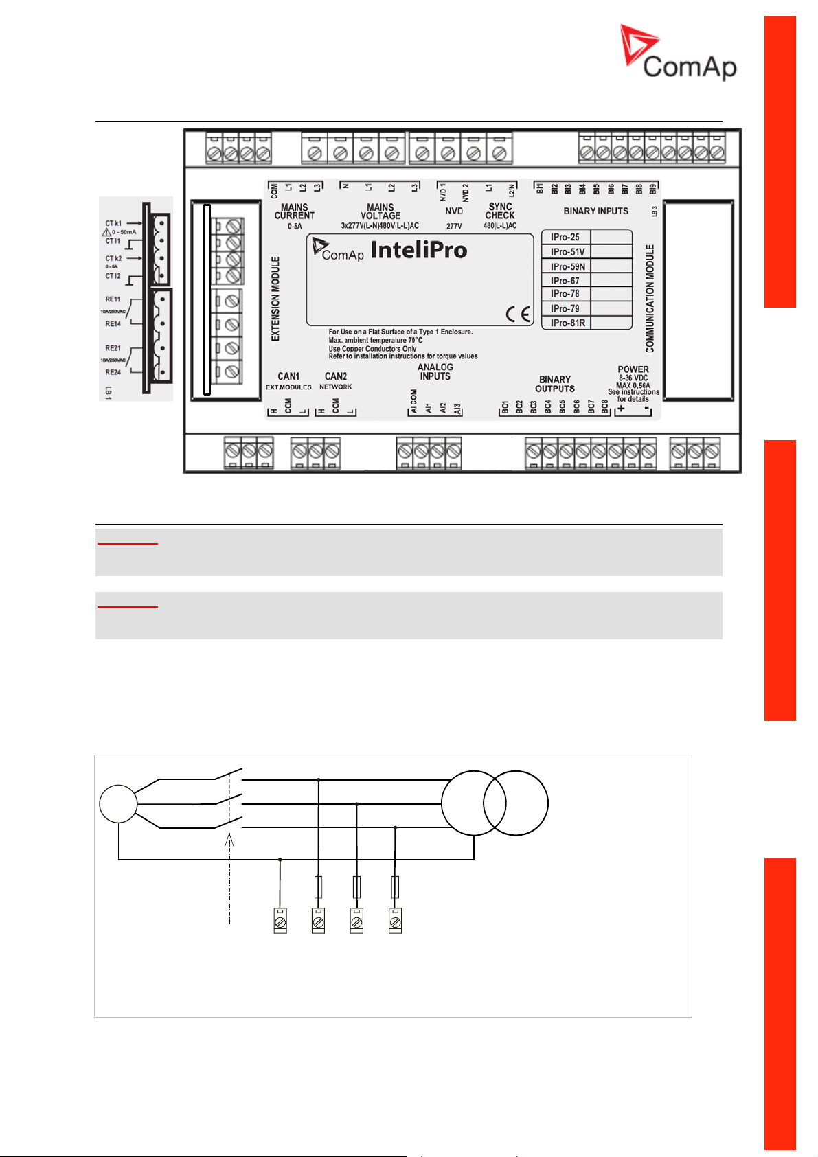
Terminal diagram
Voltage and current inputs
WARNING!
Risk of personal injury due to electric shock when manipulating with voltage terminals under voltage!
Be sure the terminals are not under voltage before touching it.
WARNING!
Do not open secondary circuit of current transformers when primary circuit is closed!!! Open the
primary circuit first!
Use 1.5 mm
Adjust nominal voltage, nominal current, CT ratio and PT ratio by appropriate setpoints in the Basic
Settings group. Learn about how to view and change setpoints in the User interface chapter.
VOLTAGE MEASUREMENT WIRING
G
2
cables for voltage connection and 2.5 mm
L1
2
for current transformers connection.
L2
L3
N
<Comm Trp> /
<Trip 1> /
<Trip 2>
MAINS
VOLTAGE
InteliPro, SW version 1.0, ©ComAp – May 2011
InteliPro Installation and Operation Guide
L3L2L1N
1-5
Page 8
L1
G
<Comm Trp> /
<Trip 1> /
<Trip 2>
VOLTAGE
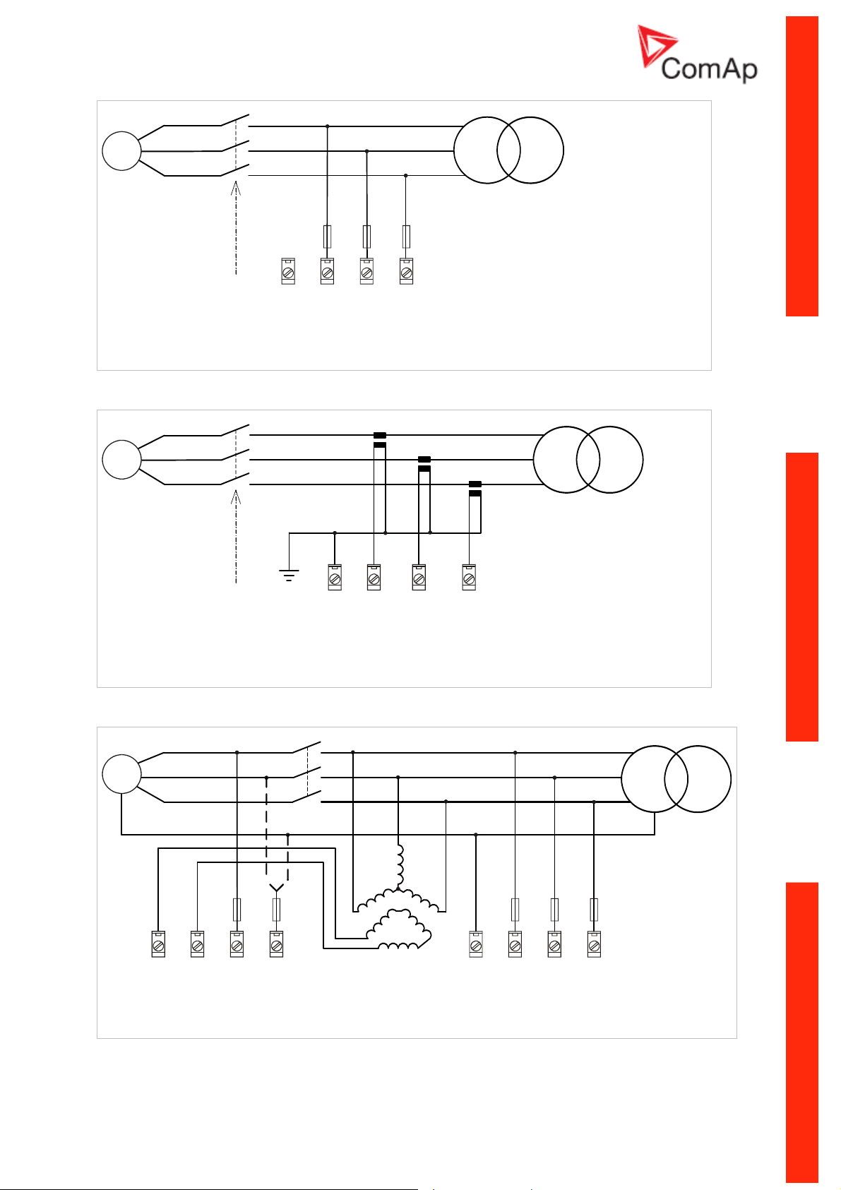
CURRENT MEASUREMENT WIRING
G
MAINS
K L
k l
L3L2L1N
L2
L3
K L
k l
K L
k l
L1
L2
L3
<Comm Trp> /
<Trip 1> /
<Trip 2>
NVD
AND SYNC CHECK WIRING
G
NVD 1
NVD 2
SYNC
NVD
CHECK
L1
COM
L2
L3
MAINS
CURRENT
L1
L2
L3
N
L2/NL1
N
L1
MAINS
VOLTAGE
L3L2
InteliPro, SW version 1.0, ©ComAp – May 2011
InteliPro Installation and Operation Guide
1-6
Page 9
Binary inputs
Use min. 1 mm
NOTE:
The name and function or alarm type for each binary input have to be assigned during the
configuration.
2
cables for wiring of binary inputs.
WIRING OF BINARY INPUTS
Binary outputs
Use min. 1 mm
below for all outputs except those where low-current loads are connected (signalization etc..).
NOTE:
The function of each output has to be assigned during the configuration.
CAUTION!
Use suppression diodes on all relays and other inductive loads!
InteliPro, SW version 1.0, ©ComAp – May 2011
InteliPro Installation and Operation Guide
2
cables for wiring of binary outputs. Use external relays as indicated on the schematic
1-7
Page 10
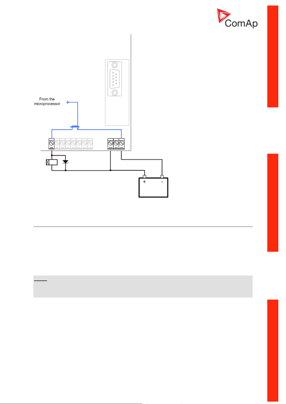
WIRING OF BINARY OUTPUTS
Analog inputs
The analog inputs are designed for resistive automotive type sensors like VDO or DATCON. The
sensors are connected either by one wire (the second pole is sensor body) or by two wires.
• In case of grounded sensors connect the AI COM terminal to the engine body as near from
the sensors as possible.
• In case of isolated sensors connect the AI COM terminal to the negative power supply
terminal of the controller as well as the opposite poles of the sensors.
NOTE:
The fail sensor alarm is issued if the measured resistance is smaller than one half of the first (lowest)
point of the sensor curve characteristic or is greater than 112,5% of the last (greatest) point of the
sensor curve characteristic.
InteliPro, SW version 1.0, ©ComAp – May 2011
InteliPro Installation and Operation Guide
1-8
Page 11
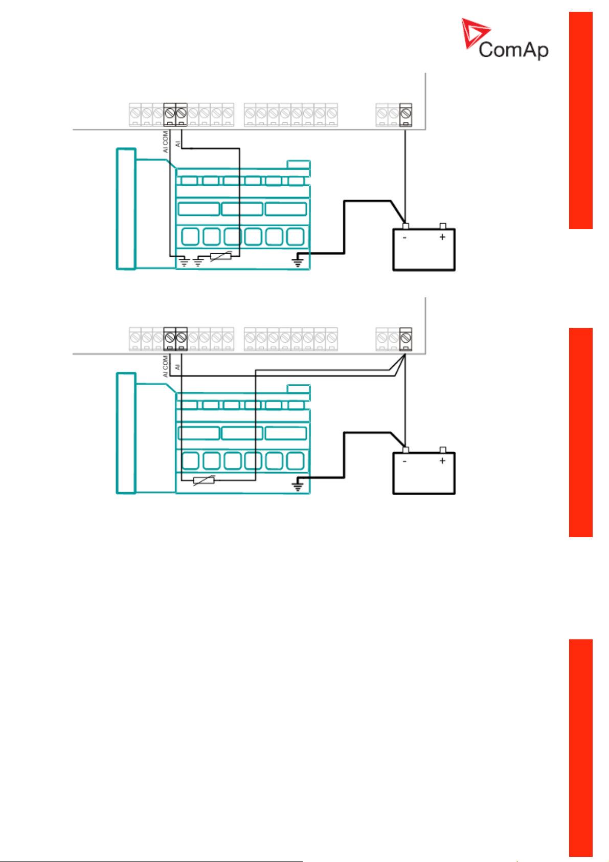
W
IRING OF ANALOG INPUTS - GROUNDED SENSORS
WIRING OF ANALOG INPUTS - ISOLATED SENSORS
Tristate inputs
Analog inputs can be used also as binary or tristate, i.e. for contact sensors without or with circuit
check. The threshold level is 750Ω. In case of tristate, values lower than 10Ω and values over 2400Ω
are evaluated as sensor failure (short or open circuit).
InteliPro, SW version 1.0, ©ComAp – May 2011
InteliPro Installation and Operation Guide
1-9
Page 12
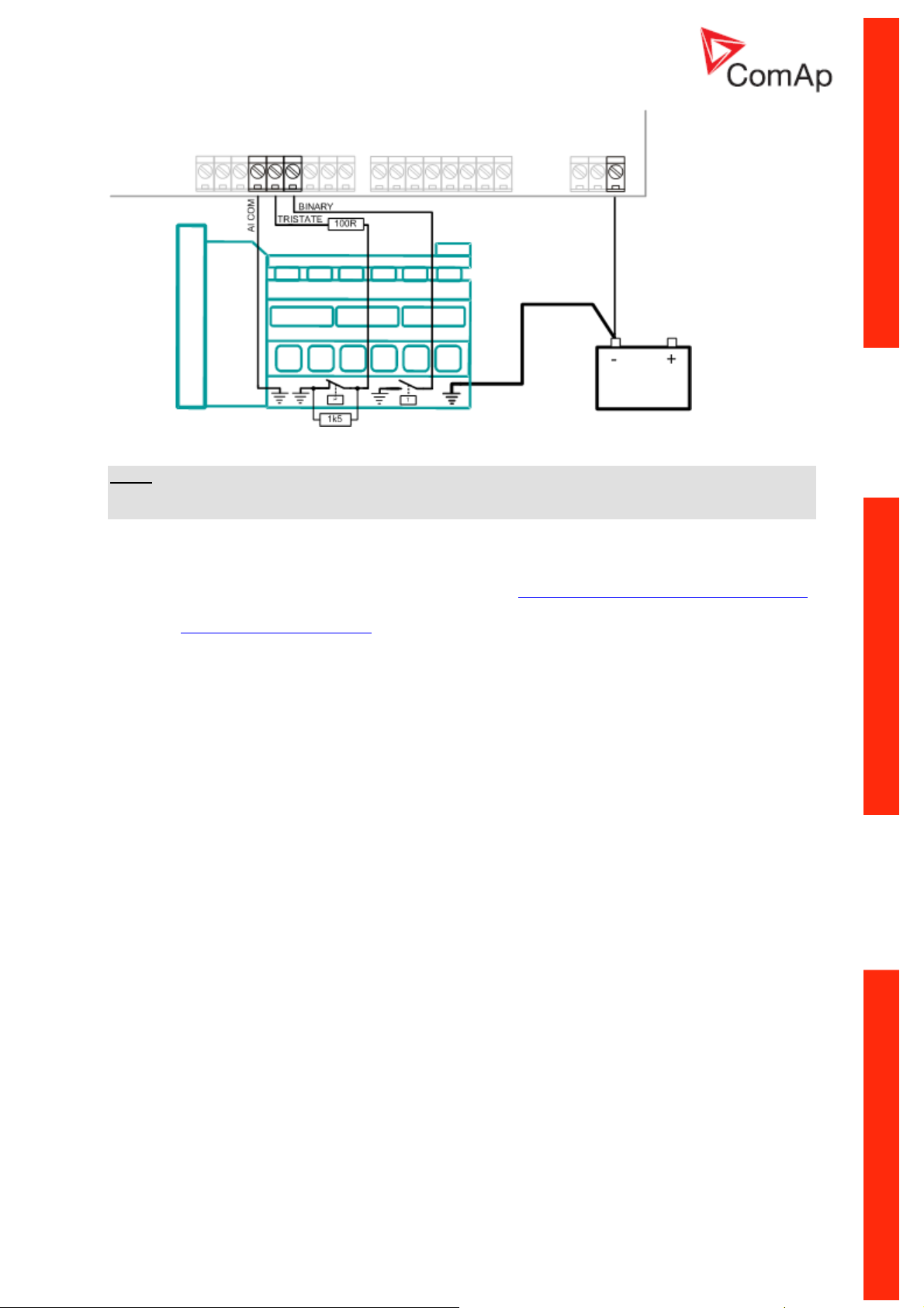
WIRING OF ANALOG INPUTS - USED AS BINARY OR TRISTATE
NOTE:
The name, sensor characteristic and alarm types for each analog input have to be assigned during the
configuration.
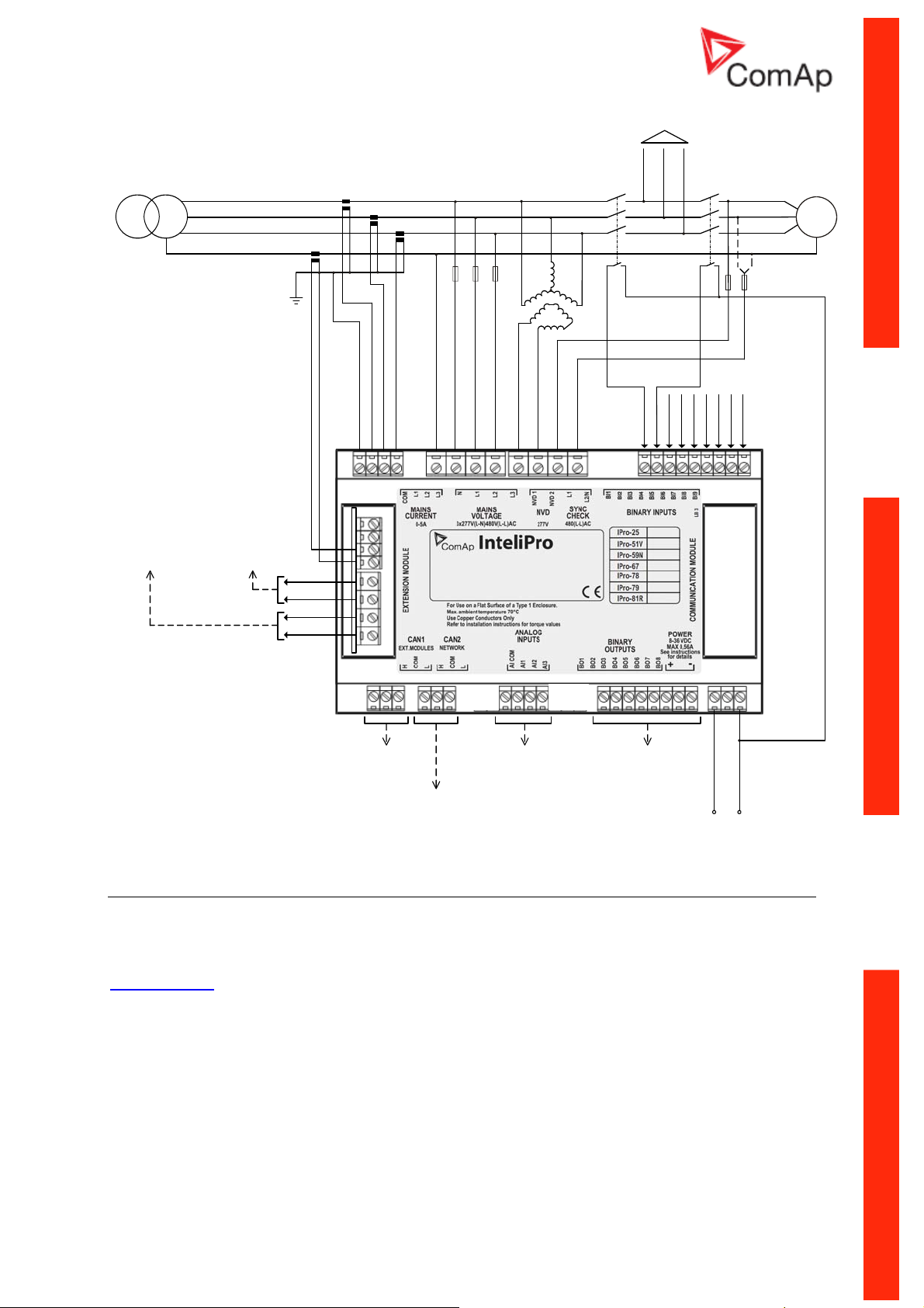
Recommended wiring
In the diagram below, see the typical wiring of the InteliPro unit inputs and outputs. The wiring is to be
considered as an example for the default configuration and operation mode with 1 common trip output
The relay contacts of Relay Card CT2-REL2 module can be reconfigured to Trip 1 and Trip 2 outputs
in case of operation with 2 trip outputs
particular needs of the application.
, as well as any inputs and outputs can be reconfigured to the
.
InteliPro, SW version 1.0, ©ComAp – May 2011
InteliPro Installation and Operation Guide
1-10
Page 13
LOAD
dry contact to
CB1 backup
L1
L2
L3
N
dry contact to
CB1 OFF coil
K L
k l
!Comm Trp
K L
k l
K L
k l
K L
k l
CB1
(MCB)
CB2
(GCB)
G
Block 2
Block 1
CB1 Feedback
CB2 Feedback
Alar m 8
F.R. But ton
Alar m 9
Access Lock
DC Tri p Cir cuit
!Bak Comm Trp
CAN bus to
extension
analog
inputs
open collector bin.
outputs (signalling)
modules
CAN bus to
ComAp
controllers
+ -
Configurability
One of the key features of InteliPro unit is high level of flexibility and adaptability of the system to the
particular application. The way how to achieve this is the configuration. Use LiteEdit PC software to
read the configuration from the controller or disk, view it, modify it and write the configuration to
controller or disk. To work with InteliPro, LiteEdit version 4.5.2 or higher is necessary. Visit
www.comap.cz
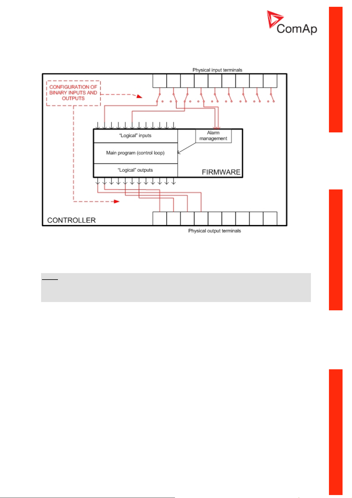
The firmware contains large number of binary inputs and outputs. However, not all functions are
required the application, also the controller hardware does not as many input and output terminals.
One of main tasks of the configuration is mapping of "logical" firmware input and output signals to the
"physical" hardware inputs and outputs.
Configuration parts:
1. Mapping of logical binary inputs (functions) or assigning alarms to physical binary input
terminals
2. Mapping of logical binary outputs (functions) to physical binary output terminals
3. Assigning sensor characteristics and alarms to analog inputs
4. Assigning control values and output characteristics to analog outputs
for download or update of this PC application.
InteliPro, SW version 1.0, ©ComAp – May 2011
InteliPro Installation and Operation Guide
1-11
Page 14
5. Selecting of peripherial modules which are connected to the controller and doing the same as
above for them
6. Changing language of the unit texts
PRINCIPLE OF BINARY INPUTS AND OUTPUTS CONFIGURATION
The unit is delivered with a default configuration, which should fit to most standard applications.
This default configuration can be changed only using PC and LiteEdit software. See LiteEdit
documentation for details.
NOTE:
You need one of communication modules to connect the controller to a PC with LiteEdit. There is a
special easy removable service module for cases, where there is no communication module
permanently attached.
Once the configuration is modified, it can be stored in a file for later usage with another controller or
for backup purposes. The file is called archive and has file extension "aic". An archive contains full
image of the controller at the moment of saving (if the controller is online to the PC) except firmware,
i.e. besides configuration there are also current adjustment of all setpoints, all measured values, copy
of history log and copy of alarm list.
The archive can be simply used for cloning of InteliPro units, which means preparing units with
identical configuration and settings.
InteliPro, SW version 1.0, ©ComAp – May 2011
InteliPro Installation and Operation Guide
1-12
Page 15
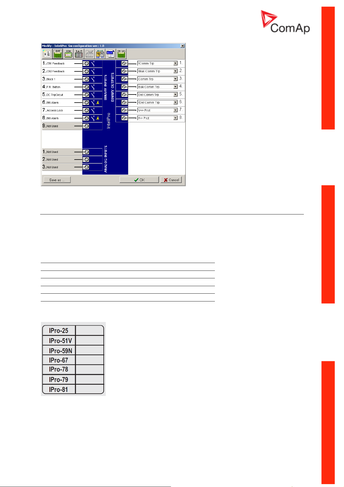
CONFIGURATION WINDOW IN LITEEDIT
Options system
The unit offers wide range of protective functionalities. To allow flexibility of the protective functions at
the particular application, some of the features are provided as SW options. These functions are
unlocked by a software dongle, delivered by ComAp or its approved distributors. The SW dongle is a
unique number generated according to the serial number of the unit and the selected protective
functions. The functions are referred by their ANSI numbers, according to the following table:
IPro-25 Synch Check
IPro-51V Time over current with voltage control
IPro-59N Neutral voltage displacement
IPro-67 Directional overcurrent
IPro-78 Vector shift
IPro-79 AC reclosing relay
IPro-81R Rate of change of frequency + rocof filter
The appropriate selection of InteliPro optional functions is to be marked on the rear side of the unit:
For unlocking the desired functions or changing those functions that are already unlocked, contact
your sales person for the appropriate SW dongle. The following information will be needed:
- Serial number of the unit
- List of requested functions to unlock
InteliPro, SW version 1.0, ©ComAp – May 2011
InteliPro Installation and Operation Guide
1-13
Page 16

Entering the SW dongle:
once received the appropriate SW dongle relative to the unit serial number, go to the setpoint Basic
Settings: Dongle and enter the numerical string, which you have obtained. Though it is more
convenient to enter the SW dongle via LiteEdit PC software, it is also possible to enter it through the
controller screen and pushbuttons.
InteliPro, SW version 1.0, ©ComAp – May 2011
InteliPro Installation and Operation Guide
1-14
Page 17
User Interface
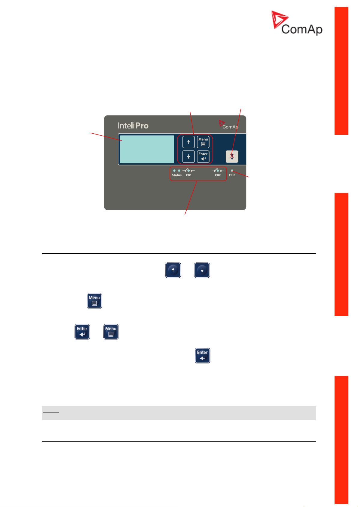
128 x 64
pixels
graphical
display
Control and
navigation
pushbuttons
Fault Reset
button
TRIP LED
Signalization
LEDs
Control and navigation Pushbuttons - basic operation
General operation using buttons:
• In the measurement screens, use the
measured values as displayed on the graphical display. See the chapter Measurement
screens to get the basic orientation.
• Use the
view the history table. For setpoints change, see the following chapter.
• To enter the init screen, change language or read the list of unlocked InteliPro options, push
the
performs lamp test by simultaneous blinking of all LEDs.
• For confirmation of change any setpoint, use the
Entering the password
The password must be entered prior adjusting setpoints, that are password-protected. Password is
located in the first group of setpoints and the way how to enter or change password is similar to
change of setpoints.
button to cycle through display of measurement screens, adjust setpoints and
and buttons at the same time. Together with the init screen display, the unit
and , arrow buttons to browse through the
button.
NOTE:
It is possible to change only passwords of the same or lower level than actually entered password!
Sinalization LEDs
There are 5 LEDs for indication of InteliPro status with the meaning indicated in the table below:
InteliPro, SW version 1.0, ©ComAp – May 2011
InteliPro Installation and Operation Guide
1-15
Page 18
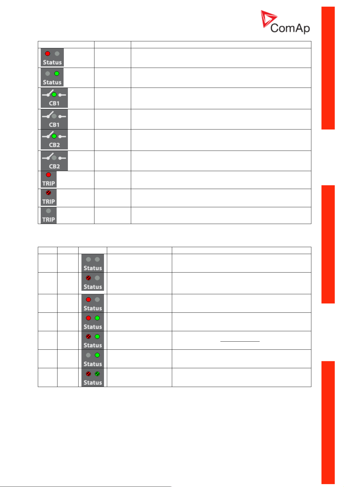
LED state Meaning
-
(red)
-
(green)
ON
(green)
OFF
Status of the InteliPro unit - used in combination with green LED, see the table below
Status of the InteliPro unit - used in combination with red LED, see the table below
CB1 feedback - activated - state "I"
CB1 feedback - deactivated - state "0"
ON
CB2 feedback - activated - state "I"
(green)
OFF
ON
CB2 feedback - deactivated - state "0"
Indicates TRIP state, measured values are in fault conditions (out of limits)
(red)
blinking
Indicates TRIP state, measured values are in fault-free conditions (within limits)
(red)
OFF
The unit is not in TRIP state
Status LED signalization:
red green state Display reading Meaning
OFF OFF
blink OFF
ON OFF
ON ON
"Program Corrupted" or
"System Error" or "System
Error + Wrong config
format"
Normal reading Wrong checksum of parameters → Check the complete settings
Normal reading Wrong checksum of "R" parameters → Contact technical support
No power supply or PowerFail occured
Transient SW failure → Contact technical support with
information abut the display message
of your unit and change any one of the parameters. If the state
persists, contact technical support
blink ON
OFF ON
blink blink
Normal reading Watchdog reset was performed → Save the archive, contact
Normal reading Normal operation of the unit
Not initialized Unit HW failure → Request repair of the unit
InteliPro, SW version 1.0, ©ComAp – May 2011
InteliPro Installation and Operation Guide
technical support and attach the archive
1-16
Page 19

InteliPro
Protection Relay for Parallel Applications
Application Guide
SW version 1.0, May 2011
Application Guide
Copyright © 2011 ComAp s.r.o.
Written by Tomas Jelen
Prague, Czech Republic
ComAp, spol. s r.o.
Kundratka 2359/17, 180 00 Praha 8, Czech Republic
Tel: +420 246 012 111, Fax: +420 246 316 647
E-mail: info@comap.cz, www.comap.cz
Page 20

Table of contents
Introduction.............................................................................................................................................. 2
Operation mode with 1 common trip output........................................................................................ 3
Operation mode with 2 trip outputs ..................................................................................................... 4
Priority switching ................................................................................................................................. 4
TRIP and Fault Reset description ....................................................................................................... 5
TRIP................................................................................................................................................ 5
Fault reset ....................................................................................................................................... 5
Shared peripheries.............................................................................................................................. 5
Protective functions ................................................................................................................................. 7
The concept......................................................................................................................................... 7
Protective functions in detail ............................................................................................................... 8
Overvoltage, Undervoltage (ANSI 59, 27) ...................................................................................... 8
Overfrequency, Underfrequency (ANSI 81 H, L)............................................................................ 8
Voltage unbalance (ANSI 47) ......................................................................................................... 8
"Loss of mains" protections ............................................................................................................ 8
Vector shift (ANSI 78) ..................................................................................................................... 8
Rate Of Change Of Frequency (df/dt, ROCOF, ANSI 81R) ........................................................... 9
Overcurrent: definite-time, IDMT and with voltage control ........................................................... 10
Neutral overcurrent (ANSI 50N, ANSI 51N) ................................................................................. 11
Current unbalance (ANSI 46) ....................................................................................................... 11
Directional overcurrent (DOC, ANSI 67)....................................................................................... 11
Neutral Voltage Displacement (NVD, ANSI 59N)......................................................................... 12
Directional power (ANSI 32) ......................................................................................................... 12
Synchro check (ANSI 25) ............................................................................................................. 13
AC reclosing (ANSI 79)................................................................................................................. 13
InteliPro, SW version 1.0, ©ComAp – May 2011
InteliPro Application Guide
2-2
Page 21

Introduction
InteliPro protection relay provides high range of flexibility to the users and their applications. In the
most common cases, one output for tripping is used. In this case, InteliPro allows provides the
common trip output, which represents logical "OR" of all activated and pre-set protective functions of
the unit. If needed, InteliPro also allows to operate two circuit breakers, where some protective
functions are assigned to one of them and other functions to the other. In such case, the circuit
breakers can provide backup for each other, so that in "fail to trip" situation the other circuit breaker
opens under pre-set conditions to clear the first breaker failure.
Furthermore, InteliPro provides two independent blocking inputs, which can be used to activate or
deactivate any of the protective functions of the unit. All necessary inputs and outputs can be freely
configured to any input or output of the unit. In case of outputs, any of the 2 relay outputs or 8 opencollector outputs can be selected.
In case that any of the configured protective functions is activated, InteliPro relay provides a Trip
signal. This signal is provided in both positive and negative logic in order to follow the requirements of
the application:
• Due to increased safety requirements, some protective relays require that negative logic is
used, assuring that loss off power supply always causes the relay to trip. I.e. the relay
contacts are used, with fault-free position maintained in energized state. In case of power
supply fail, the unit goes to “fault” indication position. The outputs using negative logic are
marked with exclamation mark "!" as the first character of their name.
• In some applications, the negative logic is not a required functionality. The function of opening
the circuit breaker in case of loss of power supply is not accepted as a safety point and the
safety is assured by different means e.g. in the superior system or within the protection relays
intertripping scheme. In such case, the outputs with positive logic (without the exclamation
mark) can be used to signal the detected failure state.
In any case, it must be assured that the InteliPro relay has full control at opening the appropriate
breaker by the trip command - i.e. in case of Trip state the unit receives the appropriate CB
feedback, confirming its open position. The feedback must repond within preset time to the trip
command. A special attention should be paid to opening of motorized circuit breakers, as it could
take more than 2s on some types. In such cases it is necessary to use undervoltage coil for fast
opening.
Operation mode with 1 common trip output
• This is the essential mode of operation of the protection relay InteliPro. In this case, CB1
circuit breaker or contactor is considered as the main connection device, protected by
InteliPro. In the ComAp controllers, this breaker is called "Mains Circuit Breaker" = MCB.
• Second circuit breaker or contactor is not expected in the protection scheme, but there is still
possibility to use the "backup trip" signal from InteliPro relay to operate any backup device, if
present on the installation. As such device may be considered another circuit breaker in the
line of mains-connection, CB1 undervoltage coil, or any device which serves as a backup in
case of the CB1 fail.
• The Comm Trp (or !Comm Trp) output is used as the main signal to open the CB1 circuit
breaker. InteliPro expects that in such case, the CB1 Feedback input deactivates as a result of
the protection trip. Adjustable delay can be set by the setpoint General: BackupTrp Del, to
provide backup functionality for the CB1 breaker. If the feedback does not deactivate within
this delay, the output Bak Comm Trp activates (or !Bak Comm Trp deactivates) immediately.
• An function, which is activated and not blocked within the InteliPro unit activated the Comm
Trp signal. Use the blocking inputs to control which protective functions will be used under the
appropriate circumstances.
InteliPro, SW version 1.0, ©ComAp – May 2011
InteliPro Application Guide
2-3
Page 22

Operation mode with 2 trip outputs
• In some cases, the protection relay is requested to operate two circuit breakers. Usually, one
of them is considered as the main circuit breaker, with most of the functions configured to
operate this cicrcuit breaker. As mentioned above, this breaker often corresponds to the
"Mains Circuit Breaker" = MCB as used in ComAp controllers.
• The second circuit breaker can be from the point of view of the protection relay considered as
a supplementary connection device in the power connection scheme. It can provide back-up
functionality in case that the CB1 does not trip on command, or can be operated individually
by selected protective functions. It can, but does not necessarily have to correspond to the
"Generator Circuit breaker" = GCB as used in the ComAp controllers applications. In such
case, e.g. NVD function is the most often case, when GCB (CB2) is tripped instead of MCB
(CB1).
• In case that 2 circuit breakers are controled by InteliPro unit, it is possible to freely assign,
swap or configure the functionalities of both circuit breakers and provide appropriate back-up
function of the breakers by the "Priority switching" functionality. It is not practical to use the
Comm Trp output in this case. To distinguish between the 2 breakers, outputs Trip 1 and Trip
2 are available.
• For each protective function in InteliPro, it is possible to assign either Trip 1 or Trip 2 function,
none of them, or both. The setpoint xxx Trp BO in the appropriate group of protection setting is
used for this assignment. By this setting, the output Trip 1 or 2 will then contain only those
functions which were assigned to it.
• Trip 1 output is internally interconnected with CB1 operation, i.e. in case of activation of Trip 1,
the CB1 feedback is expected to deactivate. The same applies for Trip 2: in case of activation
of Trip 2, the CB2 feedback is expected to deactivate.
Priority switching
Priority switching feature allows using the circuit breakers CB1 and CB2 as a backup to the other one.
To clearly understand this, it is necessary first to understand the possibility of assignment of any of the
operated two circuit breakers to the appropriate protective function (see the chapter Operation mode
with 2 trip outputs).
Though both of the breakers are equivalent and fully assignable within the InteliPro relay, the most
common application for generator-to-mains connection is as follows:
• CB1 is considered as the main connection device of the generator to the mains. In ComAp
products, this breaker is called "Mains Circuit Breaker" = MCB.
• CB2 is considered as a supplementary connection device on the power connection between
generator and mains. There can be specific protection functions assigned the trip CB2 only
and it can provide back-up functionality to the CB1. It can, but does not necessarily have to
correspond to the "Generator Circuit breaker" = GCB as used in the ComAp products.
• As both circuit breakers are equivalent, it is possible to assign CB2 as the main one and CB1
as the backup, or provide a symmetrical backup of both breakers "one to each other".
Depending on setting the setpoint General: Prio Switching, the following backup function is provided:
DISABLED - no CB backup is provided
CB1 -> CB2 - CB1 is considered as the primary switch. If the feedback is not deactivated within preset
period after Trp 1, the output Trp 2 is issued immediately to trip CB2 as backup. Bak Trp 1 is issued at
the same time.
CB1 <- CB2 - CB2 is considered as the primary switch. If the feedback is not deactivated within preset
period after Trp 2, the output Trp 1 is issued immediately to trip CB2 as backup. Bak Trp 2 is issued at
the same time.
CB1 <-> CB2 - both CBs provide a backup switching for each other. If the CB1 feedback doesn't
deactivate in preset period, CB2 is tripped, if the CB2 feedback doesn't come in preset period, CB1 is
tripped.
InteliPro, SW version 1.0, ©ComAp – May 2011
InteliPro Application Guide
2-4
Page 23

TRIP and Fault Reset description
TRIP
TRIP may be considered as event or status of the unit:
TRIP event:
− Starts in the moment of terminating the count-down of any protective function with delay, or in the
moment of activation of any immediate protective function.
− As a result of the trip event, are e.g. the following consequences:
o Immediate deactivation of outputs !Comm Trp
o LED TRIP goes to red
o History record is created
TRIP status:
− Starts at the moment of TRIP event
− During this status, the !Comm Trp output keeps in the fault position
− During this status, it is not possible to perform Fault reset
− TRIP status is active until a successful Fault reset. This may not be done before all measured and
evaluated values are within preset limits.
− If during the TRIP status, caused by some value, another value overreached its limits for TRIP
evaluation, this second overreach is not considered as TRIP. It does not cause a second TRIP
event. However, as a consequence of this, the TRIP duration may be prolonged until the moment
when both (all) values are within limits.
Fault reset
Fault reset is an event, caused by either of the following reasons:
− Fault reset
− Input input F.R. Button is activated
− Automatic fault reset is performed according to the setting of General: Auto FR setpoint.
− By activation or deactivation of binary input Block 1 or Block 2.
The abovementioned reasons are a trigger to provide Fault reset, however, it is successfully done only
in case that the TRIP status is activated and all evaluated values have returned back into limits. If the
TRIP status is not activated, or it is activated, but any of the values is still out of limits, Fault reset is
not done and any of the mentioned triggers is forgotten. I.e., the unit may not be „provisionally“ faultreset.
By a successful Fault reset, the TRIP status is terminated.
button is pressed
Shared peripheries
The function is compatible with IG/IS-NT controllers. CAN2 interconnection between the gen-set
controllers and InteliPro is necessary to allow this feature. Use the LiteEdit configuration window to
configure the appropriate binary and analog values to be transmitted from InteliPro via the CAN2
communication. In the Configuration window, click the
button. The following window opens:
InteliPro, SW version 1.0, ©ComAp – May 2011
InteliPro Application Guide
2-5
Page 24

Using the "Module address" selection box to adjust the address of the shared peripheries module and
avoid collision with other module already present on CAN2 bus. Click on the appropriate Binary output
or Analog output in the list to set-up the value to be transmitted via CAN2 bus to the gen-set
controllers. The transmitted values are received by the IG/IS-NT controllers connected via the CAN2
bus. See more about configuring shared peripheries (Shared and Internal virtual I/O periphery and
PLC) in IGS-NT-Application guide.
The shared binary and analog outputs can be used for communicating out the binary statuses of CBs,
trips of the particular protective functions or transmitting the value of mains import in kW, kVAr or kVA
and further processing e.g. for the gen-set control or visualization of the site.
InteliPro, SW version 1.0, ©ComAp – May 2011
InteliPro Application Guide
2-6
Page 25

Protective functions
The concept
InteliPro is a modular electronic protective relay, providing complete list of protective functions. Each
of the functions works as an autonomous protective stage, with its independent activation, setting of
the limits and assigning of the Trp 1 and/or Trp 2 output and Block 1 and/or Block 2 input. Besides
that, each activated protective function activates the Comm Trp output as described above. These
settings are done in the setpoints menu, using the appropriate group of setpoints, assigned to its
function. E.g. setting of overcurrent limits, trip outputs and blocking inputs is done in the setpoint group
I>.
Activation/deactivation of a protective function:
In order to activate or deactivate a protective function, it is possible to use 2 means:
- In the setpoint group General, find the appropriate name of the function (e.g. Overcurr Prot for
overcurrent protection stage) with the possible setting: ALLWAYS / PARALLEL / DISABLED.
To deactivate the complete protective stage in general, set this setpoint to DISABLED. To
activate the protective stage in general, set the setpoint either to PARALLEL to activate this
protective in case of both CB1 and CB2 are closed, or to ALWAYS to activate the function
permanently regardless of the circuit breakers status.
- In order to e.g. activate only one adjustable pickup used within a multiple-stages protective
function, set this pickup limit to zero. E.g. InteliPro allows setting 2 stages of overvoltage
protection. To use only V> and block the V>> stage, set the pickup limit V>> to 0V. In general,
setting of any pickup limit of any protective function blocks this protection stage.
- To operatively enable or disable a protective stage during regular operation of the unit, assign
the Block 1 and Block 2 inputs to the appropriate protective function. By activation and
deactivation of those inputs, enable or disable the appropriate protective stage. Enabling of a
protection stage is delayed by ProtActiv del after deactivation of the blocking input.
- It is possible, that in your unit, some optional protective functions are not activated. In such
case, the function is permanently blocked and even the setpoints related to it are not visible. In
case that this protection is requested, please consult your sales representative regarding the
options unlocking.
How to set-up trip outputs
To assign the appropriate trip outputs, which are operated by a particular protective stage, find the
setpoint group, which contains the setting of this protective stage. E.g. for overcurrent, go to the
setpoint group I>. In the setpoint group find the setpoint xxx Trp BO, where "xxx" is the abbreviation of
the protective stage. It is possible to use the following setting:
- None: neither Trp 1 nor Trp 2 is activated in case of this protective stage trip. In such case,
only the Comm Trp output contains information about trip by this protection stage.
- Trp 1: binary output Trp 1 is activated in case of this protection stage trip.
- Trp 2: binary output Trp 2 is activated in case of this protection stage trip.
- Trp 1+2: both binary output Trp 1 and Trp 2 are activated in case of this protection stage trip.
- In all cases, the Comm Trp output contains information about trip from all activated protection
stages.
How to set-up blocking inputs
To assign the appropriate Block inputs to enable or disable the particular protective stage, find the
setpoint group, which contains the setting of this protective stage. E.g. for overcurrent, go to the
setpoint group I>. In the setpoint group find the setpoint xxx Block BI, where "xxx" is the abbreviation
of the protective stage. It is possible to use the following setting:
- None: neither Block 1 nor Block 2 is used to enable or disable the protective stage.
- Block 1: binary input Block 1 is used to enable or disable the protective stage.
- Block 2: binary input Block 2 is used to enable or disable the protective stage.
- Block 1+2: both binary inputs Block 1 and Block 2 are used to enable/disable the protective
stage. The input signals are connected by logical OR function.
InteliPro, SW version 1.0, ©ComAp – May 2011
InteliPro Application Guide
2-7
Page 26

Protective functions in detail
Overvoltage, Undervoltage (ANSI 59, 27)
The RMS value of measured voltage is compared with the preset limit of overvoltage or undervoltage.
When any of the preset limits is over/underreached, the output U Sig moves to fault-indicating position
immediately. If the voltage of the given phase keeps out of limits for the delay of the appropriate stage,
TRIP is issued. As the voltage returns back within limits in all measured phases, the U Sig output stop
to signal the fault state immediately, regardless of whether TRIP was issued or not or Fault reset was
performed or not.
Both overvoltage and undervoltage protective stages provide possibility of setting 2 levels with
independent delay assigned to each level.
Overfrequency, Underfrequency (ANSI 81 H, L)
The frequency value measured on phase L1 is compared with the preset limit of overfrequency or
underfrequency. When any of the preset limits is over/underreached, the output f Sig moves to faultindicating position immediately. If the frequency keeps out of limits for the delay of the appropriate
stage, TRIP is issued. As the frequency returns back within limits, the f Sig output stops to signal the
fault state immediately, regardless of whether TRIP was issued or not or Fault reset was performed or
not.
Both overfrequency and underfrequency protective stages provide possibility of setting 2 levels with
independent delay assigned to each level.
Voltage unbalance (ANSI 47)
The voltage unballance is evaluated in case that amplitude difference between any 2 phases
overreaches the preset limit V Unb: V Unb. It refers to the amplitude unbalance of the measured
voltage.
"Loss of mains" protections
InteliPro provides two different methods for fast evaluation of loss of mains (LOM), into which the generator
operates:
- Vector shift
- Rate Of Change Of Frequency
The loss-of-mains protections setting is done using the setpoints in the group LOM.
Vector shift (ANSI 78)
Vector shift is one of the LOM protections. It provides very fast detection of mains failure (in units or
tens of ms), based on the principle of shift of the synchronous generator displacement angle. The
displacement angle is an angle between magnetic field of a rotor and the rotating magnetic field of the
stator winding and relates strongly to the load of the generator. In case that this load changes, the
displacement angle immediately changes by a "jump". Compared to the frequency decrease, which
probably also occurs, this jump is an immediate phenomena and is detected as a shift of the
measured voltage sine curve - Vector shift or Vector jump. Depending on the preset limit in degrees
[°], it allows immediate disconnection of very fast failures and thus prevention of severe damages
which could not be prevented within the delay of frequency or voltage protections.
InteliPro, SW version 1.0, ©ComAp – May 2011
InteliPro Application Guide
2-8
Page 27

Vector shift reaction times are usually requested up to 30ms. Typical setting is shown e.g. in G59/2
standard (see below).
Rate Of Change Of Frequency (df/dt, ROCOF, ANSI 81R)
ROCOF is second most frequently requested method of LOM detection. In principle, the method uses
similar evaluation method like Vector shift, but the physical phenomena detected is different. It
calculates the change of speed of the generator, caused by sudden change in its load, together with
unintentional islanding situation (loss of mains), which is normally capable of keeping the frequency on
a stable level. The frequency change is expressed as tangent in time [Hz/s]:
InteliPro, SW version 1.0, ©ComAp – May 2011
InteliPro Application Guide
2-9
Page 28

It is a fast protection, similar to Vector shift, however, unlike Vector shift, which detects immediate
phenomena, the tangent calculation requires a certain time for evaluation. In ComAp protection relays,
the evaluation time for ROCOF protection can be adjusted in number of sine curve cycles being taken
into evaluation from 1 to tens of cycles (each having 20ms). This allows to set up the ratio between the
evaluation speed and sensitivity to nuisance trips.
Overcurrent: definite-time, IDMT and with voltage control
InteliPro provides three types of mains-overcurrent with different setting of the protection delay:
Definite time overcurrent (ANSI 50):
The trip is issued in a given delay after the current exceeds preset limit. The setting is done using the
setpoints
IDMT overcurrent (ANSI 51)
The IDMT (inverse definite minimum time) overcurrent provides delayed overcurrent trip, based on
calculation of the trip delay according to the trip curve:
in the group I>.
I> Del
The delay, i.e. the IDMT curve shape is prescribed by the DNO, based on the calculations of shortcircuit conditions in the point of the generator connection. The grid protections are coordinated and
allow for isolating the faults by the protections which are located closer to the short-circuit area. This
way, the discrimination of the breakdown point is done by the short-circuit current magnitude allowing
the generator to ride-through a distant faults and contribute to recover the mains voltage after the fault
is disconnected. The setting is done using the setpoints
The shape of IDMT curve can be selected using the parameter I> T: I> T Curve. If the option IDMT is
selected, the shape is given by the following formula:
in the group I> T.
I> Del *
The parameter I> T: I> T Curve allows also to set other switching curves according to the IEC
standards.
InteliPro, SW version 1.0, ©ComAp – May 2011
InteliPro Application Guide
2-10
Page 29

Time overcurrent with voltage control and restraint (ANSI 51V)
The voltage control of time overcurrent assures that the protection is blocked in case that the
measured voltage is above the level set by the setpoint I> V: I> V Control.
The voltage restraint function is a modification of the IDMT overcurrent protection. It uses the same
mechanism of the delay calculation according to the IDMT trip curve, but the delay is further adjusted
according to the measured voltage:
This protection functionality uses the fact that voltage in the point of short-circuit drops to zero or very
low values and with growing distance from the fault, it increases up to the mains nominal voltage
value. Thus, increased sensitivity to the short-circuits localization and protection coordination is
provided. The setting is done using the setpoints
in the group I> V.
Neutral overcurrent (ANSI 50N, ANSI 51N)
To allow measurement of the neutral overcurrent, the plug-in module Relay Card CT2-REL2 is
necessary. The protection stage allows to set up instantaneous neutral overcurrent or IDMT
overcurrent, similar to the mains overcurrent protective functions. The setting is done using the
setpoints group EFC.
Current unbalance (ANSI 46)
The current unbalance protection is used to avoid unballanced load in the point of mains connection.
The setting is done using the setpoints in the setpoint group I Unb.
Directional overcurrent (DOC, ANSI 67)
DOC is sensitive for location of the fault with relation to the measurement point. This way, directional
protection is capable to detect whether the fault happened "in front of it" or "behind". Directional
overcurrent protection, applied in the point of generator connection to mains, is considered a loss of
mains protection, however it does not substitute the traditional loss of mains protections like Vector
shift or ROCOF. The typical application is a generator running in parallel to mains with its own load
consumption (e.g. peak shaving, soft transfer stand-by, or other applications). The generator is usually
used to support the local consumption with no export to the mains. In case of mains transition into an
island mode, the generators, running in parallel with the islanded area, would start to supply its
complete consumption, generating current in opposite direction. DOC protection is used to avoid this
situation, and trip the generator from the islanded mains, combining the overcurrent protection
together with its directional character. Compared to the "reverse power protection", DOC protection
detects also reactive currents from the given angle zone, what allows better sensitivity for tripping.
InteliPro, SW version 1.0, ©ComAp – May 2011
InteliPro Application Guide
2-11
Page 30

The following image shows the conditions of activation of Directional Overcurrent protection in
InteliPro – i.e. critical angles between voltage and current, given the voltage is placed at the 0°angle:
90°
150°
0°
DOC>
Base angle
-135°
The setting is done using the setpoints in the group DOC.
Trip area
-60°
-90°
Neutral Voltage Displacement (NVD, ANSI 59N)
NVD protective function is used in medium or high voltage systems with isolated or indirectly grounded
zero-point. Under healthy conditions of the system, the sum of the three phase-to-earth voltages
should balance to zero. When an earth-fault occurs, it does not cause a short-circuit, because of the
isolation of the system in the zero point. However, the fault provides connection of one phase with
earth what represents hazard for the system safety (ground-fault in any other phase would then mean
a phase-to phase short-circuit, phase-to-ground voltage of the other phases may fluctuate to multiples
of its nominal, providing increased stress to the isolation system, etc). One of the effects of the fault is
a rise in the neutral voltage, so called neutral voltage displacement. This neutral voltage displacement
is measured in a specific "open-delta" connection of voltage transformers, shown in the chapter
Voltage and current inputs. In some cases, it is required to clear the fault by tripping the appropriate
circuit breaker. However, the NVD protection itself does not allow detecting the location of a fault and
for this reason it is sometimes used only for providing an earth-fault alarm.
It is possible to set whether the NVD contributes to the common trip of the relay or uses its own
separate output for signalization of the NVD alarm. The setting is done using the setpoints in the group
NVD.
Directional power (ANSI 32)
InteliPro provides two stages of power protections, both of them allowing setting of either overreaching
the preset limit or underreaching it. This way, all of the following protections are realized:
- Mains reverse power (protection of unintentional export)
- Generator reverse power (protection of motoric operation)
- Minimum import underreaching (timely trip in case of unintentional export approaching)
InteliPro, SW version 1.0, ©ComAp – May 2011
InteliPro Application Guide
2-12
Page 31

The setting is done using the setpoints in the group P<>.
Synchro check (ANSI 25)
This function checks state of synchronism at both sides of the circuit breaker. It is used as a
supplementary function to automatic reconnecting of the other functions to assure that the
synchronous conditions are met before the circuit breaker closes back by the protection relay, or is
unblocked to be closed by some other device. In InteliPro, either L1-L2 phase-to-phase voltage or L1N phase-to-neutral voltage is measured on the generator side of the circuit breaker and compared with
the corresponding measured mains voltage. Whether phase-to-phase or phase-to-neutral voltage is
used is decided by the setpoint Basic Settings: Voltage Setup. Synchronous conditions are evaluated
based on the preset window of voltage, frequency and angle match as set in the setpoint group Sync
Check.
AC reclosing (ANSI 79)
The automatic reclosing mechanism is generally used in situation, where temporary nature of the
failure is expected. The protection relay trips the breaker according to the standard protection settings.
As soon as the trip conditions disappear, i.e. the protection senses fault-free situation, the tripping
output deactivates and after a reclosing delay, the reclosing output issues a signal to automatically
reclose the breaker. There may be several reclosure attempts done in case of unsuccessful reclosure
cycle. The setting is done using the setpoints in the group AC Reclosing.
InteliPro, SW version 1.0, ©ComAp – May 2011
InteliPro Application Guide
2-13
Page 32

InteliPro
Protection Relay for Parallel Applications
Application Guide
SW version 1.0, May 2011
Communication Brochure
Copyright © 2011 ComAp s.r.o.
Written by Tomas Jelen
Prague, Czech Republic
ComAp, spol. s r.o.
Kundratka 2359/17, 180 00 Praha 8, Czech Republic
Tel: +420 246 012 111, Fax: +420 246 316 647
E-mail: info@comap.cz, www.comap.cz
Page 33

Table of contents
CAN bus and RS485 ............................................................................................................................... 2
Recommended CAN/RS485 connection............................................................................................. 4
CAN bus connection ....................................................................................................................... 4
RS485 connection........................................................................................................................... 4
Communication modules......................................................................................................................... 6
IL-NT-232 ............................................................................................................................................ 6
IL-NT-RS232-485................................................................................................................................6
IL-NT-S-USB ....................................................................................................................................... 7
IB-Lite .................................................................................................................................................. 7
InteliPro, SW version 1.0, ©ComAp – May 2011
InteliPro Communication Brochure
3-2
Page 34

CAN bus and RS485
For wiring of CAN bus communication, the following rules are to be maintained:
• Maximal length of the CAN bus depends on the communication speed. For the speed of
250kbps, which is used on the CAN1 bus (extension modules) and CAN2 bus if it is switched
to 32C mode the maximal length is 200m. If the CAN2 bus is switched to 8C mode by the
setpoint Comms settings: CAN Bus Mode, the speed is 50kbps and the maximal length is
800m.
• The bus must be wired in linear form with termination resistors at both ends. No nodes except
on the controller terminals are allowed. Use cable with following parameters:
Cable type Shielded twisted pair
Impedance 120Ω
Propagation velocity >= 75% (delay <= 4.4 ns/m)
Wire crosscut >= 0.25mm2
Attenuation (@1MHz) <= 2dB/100m
CAN BUS TOPOLOGY
InteliPro, SW version 1.0, ©ComAp – May 2011
InteliPro Communication Brochure
3-3
Page 35

NOTE:
See the web page www.can-cia.org for information about CAN bus, specifications etc.
Recommended CAN/RS485 connection
CAN bus connection
The bus has to be terminated by 120 Ohm resistors at both ends. External units can be connected on
the CAN bus line in any order, but keeping line arrangement (no tails, no star) is necessary. Standard
maximum bus length is 200m for 32C CAN BUS MODE and 900m for 8C CAN BUS MODE. Shielded
cable has to be used, shielding has to be connected to PE on one side (controller side).
1. For shorter distances (all network components within one room) – picture 1
Interconnect H and L; shielding connect to PE on controller side
2. For longer distances (connection between rooms within one building) – picture 2
Interconnect H, L, COM; shielding connect to PE in one point
3. In case of surge hazard (connection out of building in case of storm etc.) – picture 3
We recommend to use following protections:
• Phoenix Contact (http://www.phoenixcontact.com
(base element)
• Saltek (http://www.saltek.cz
): DM-012/2 R DJ
): PT 5-HF-12DC-ST with PT2x2-BE
Recommended data cables: BELDEN (http://www.belden.com
1. For shorter distances: 3105A Paired - EIA Industrial RS-485 PLTC/CM (1x2 conductors)
2. For longer distances: 3106A Paired - EIA Industrial RS-485 PLTC/CM (1x2+1 conductors)
3. In case of surge hazard: 3106A Paired - EIA Industrial RS-485 PLTC/CM (1x2+1 conductors)
)
RS485 connection
The line has to be terminated by 120 Ohm resistors at both ends. External units can be connected on
the RS485 line in any order, but keeping line arrangement (no tails, no star) is necessary. Standard
maximum link length is 1000m. Shielded cable has to be used, shielding has to be connected to PE on
one side (controller side).
1. For shorter distances (all network components within one room) – picture 1
interconnect A and B; shielding connect to PE on controller side
2. For longer distances (connection between rooms within one building) – picture 2
interconnect A, B, COM; shielding connect to PE in one point
3. In case of surge hazard (connection out of building in case of storm etc.) – picture 3 We
recommend to use following protections:
• Phoenix Contact (http://www.phoenixcontact.com
(base element)(or MT-RS485-TTL)
• Saltek (http://www.saltek.cz
Recommended data cables: BELDEN (http://www.belden.com
): DM-006/2 R DJ
): PT 5-HF-5DC-ST with PT2x2-BE
)
1. For shorter distances: 3105A Paired - EIA Industrial RS-485 PLTC/CM (1x2 conductors)
2. For shorter distances: 3105A Paired - EIA Industrial RS-485 PLTC/CM (1x2 conductors)
3. In case of surge hazard: 3106A Paired - EIA Industrial RS-485 PLTC/CM (1x2+1 conductors)
InteliPro, SW version 1.0, ©ComAp – May 2011
InteliPro Communication Brochure
3-4
Page 36

PICTURE 1 - SHORTER DISTANCES (ALL NETWORK COMPONENTS WITHIN ONE ROOM)
PICTURE 2 - LONGER DISTANCES (CONNECTION BETWEEN ROOMS WITHIN ONE BUILDING)
ICTURE 3 - SURGE HAZARD (CONNECTION OUT OF BUILDING IN CASE OF STORM ETC.)
P
InteliPro, SW version 1.0, ©ComAp – May 2011
InteliPro Communication Brochure
3-5
Page 37

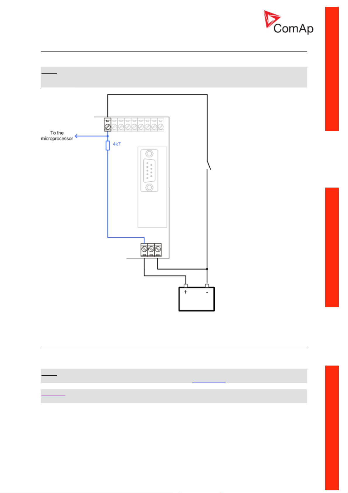
Communication modules
Communication module enables connection of a remote computer or other remote device such as
PLC to InteliPro. The module is to be plugged-in into the slot in the rear side of InteliPro. The slot is
accessible after slot cover is removed.
SLOT FOR COMMUNICATION MODULES
NOTE:
The modules are compatible with ComAp IL-NT and IC-NT controllers.
IL-NT-232
This module contains a RS232 port with all modem signals connected internally to the COM1 of the
controller. DB9M connector is used on the RS232 side.
RS232 PINOUT AND CABLE WIRING
IL-NT-RS232-485
The IL-NT-232-485 is a dual port module with RS232 and RS485 interfaces at independent COM
channels. The RS232 is connected to COM1 and RS485 to COM2.
InteliPro, SW version 1.0, ©ComAp – May 2011
InteliPro Communication Brochure
3-6
Page 38

IL-NT-RS232-485 MODULE
IL-NT-S-USB
This module contains USB slave port connected internally to the COM1 of the controller and is
designed as an easy removable service module.
This module requires a FTDI USB Serial converter driver installed in the PC. The driver creates a
virtual serial port (COM) in the PC, which must be used in LiteEdit as communication port when a
connection is beeing opened.
NOTE:
The FTDI driver is installed together with LiteEdit.
NOTE:
When the USB cable from the controller is plugged-in first time into different USB ports on the PC
including USB hubs, it can be recognized as new hardware and the drivers are installed again with
different number of the virtual serial port.
CAUTION!
Use shielded USB cable only!
IB-Lite
IB-Lite is a plug-in module with Ethernet 10/100 Mbit interface in RJ45 connector. The module is
internally connected to both COM1 and COM2 serial channels and provides an interface for
InteliPro, SW version 1.0, ©ComAp – May 2011
InteliPro Communication Brochure
3-7
Page 39

connecting a PC with LiteEdit or InteliMonitor through ethernet/internet network, for sending active emails and for integration of the controller into a building management (Modbus/TCP protocol).
IB-LITE MODULE
Use Ethernet UTP cable with RJ45 connector for connection of the module into your ethernet network.
The module can be also connected directly to a PC using cross-wired UTP cable.
C
ROSS-WIRED UTP CABLE
For more detail about communication of ComAp products, see the IL-NT, IA-NT, IC-NT
Communication Guide as published on ComAp download centre
InteliPro, SW version 1.0, ©ComAp – May 2011
InteliPro Communication Brochure
.
3-8
Page 40

InteliPro
Protection Relay for Parallel Applications
Reference Guide
SW version 1.0, May 2011
Reference Guide
Copyright © 2011 ComAp s.r.o.
Written by Tomas Jelen
Prague, Czech Republic
ComAp, spol. s r.o.
Kundratka 2359/17, 180 00 Praha 8, Czech Republic
Tel: +420 246 012 111, Fax: +420 246 316 647
E-mail: info@comap.cz, www.comap.cz
Page 41

Table of contents
Library of binary inputs ............................................................................................................................ 2
Binary alarm and functional input configuration items.................................................................... 7
Alarm............................................................................................................................................... 7
CB1 Feedback ................................................................................................................................8
CB2 Feedback ................................................................................................................................8
F.R. Button...................................................................................................................................... 8
DC TripCircuit ................................................................................................................................. 8
Access Lock.................................................................................................................................... 8
External Trip.................................................................................................................................... 8
Block 1, Block 2 .............................................................................................................................. 8
Library of binary output functions ............................................................................................................ 9
Common Alarm............................................................................................................................... 9
Comm Trp ....................................................................................................................................... 9
!Comm Trp ...................................................................................................................................... 9
Bak Comm Trp................................................................................................................................9
!Bak Comm Trp............................................................................................................................... 9
Del Comm Trp................................................................................................................................. 9
!Del Comm Trp................................................................................................................................9
Trp 1................................................................................................................................................ 9
! Trp 1............................................................................................................................................ 10
Bak Trp 1 ...................................................................................................................................... 10
!Bak Trp 1 ..................................................................................................................................... 10
Trp 2.............................................................................................................................................. 10
! Trp 2............................................................................................................................................ 10
Bak Trp 2 ...................................................................................................................................... 10
!Bak Trp 2 ..................................................................................................................................... 10
U<> Prot........................................................................................................................................ 10
f<> Prot ......................................................................................................................................... 10
V Unb Protection........................................................................................................................... 10
PhaseRot Prot............................................................................................................................... 10
VectorS Prot.................................................................................................................................. 10
ROCOF Prot ................................................................................................................................. 11
DOC Prot ...................................................................................................................................... 11
P Prot ............................................................................................................................................ 11
I> Prot ........................................................................................................................................... 11
NVD Prot....................................................................................................................................... 11
!NVD Prot...................................................................................................................................... 11
EFC Prot ....................................................................................................................................... 11
IGS Prot ........................................................................................................................................ 11
I Unb Prot...................................................................................................................................... 11
DC Healthy.................................................................................................................................... 11
Watchdog...................................................................................................................................... 11
MaxParTime.................................................................................................................................. 11
!MaxParTime................................................................................................................................. 11
U Sig ............................................................................................................................................. 11
f Sig............................................................................................................................................... 11
U Unb Sig...................................................................................................................................... 12
LOM Sig ........................................................................................................................................ 12
I> Sig............................................................................................................................................. 12
I Unb Sig ....................................................................................................................................... 12
DOC Sig........................................................................................................................................ 12
DOC Test ...................................................................................................................................... 12
EFC Sig......................................................................................................................................... 12
IGS Sig.......................................................................................................................................... 12
NVD Sig ........................................................................................................................................ 12
P Sig ............................................................................................................................................. 13
Sync Check................................................................................................................................... 13
InteliPro, SW version 1.0, ©ComAp – May 2011
InteliPro Reference Guide
4-2
Page 42

AC Reclosing ................................................................................................................................13
CB1 Protection.............................................................................................................................. 13
CB2 Protection.............................................................................................................................. 13
Self Test........................................................................................................................................ 13
AL AIx Wrn/Trp, AL IOM AIx Wrn/Trp........................................................................................... 13
AIx Wrn/Trp Sig, IOM AIxWrn/Trp Sig .......................................................................................... 13
AL Aux Volt ................................................................................................................................... 13
AL Common Wrn .......................................................................................................................... 14
AL Common Fls ............................................................................................................................ 14
BIx Status, IOM BIx Status ........................................................................................................... 14
Library of setpoints ................................................................................................................................15
Basic Settings.................................................................................................................................... 15
ControllerName............................................................................................................................. 15
Mains CT Ratio [A/5A] ............................................................................................................... 15
EF CT Ratio [A/5A] .................................................................................................................. 15
Mains PT Ratio [V/V] ................................................................................................................. 15
NomVolts Ph-N [V] .................................................................................................................... 15
NomVolts Ph-Ph [V]................................................................................................................... 15
Nominal Freq [Hz]...................................................................................................................... 16
NominMainsPwr [kW] ................................................................................................................ 16
Voltage Setup [ Ph To N / Ph To Ph ]........................................................................................ 16
CB1 Prot Timer [s] ..................................................................................................................... 16
CB2 Prot Timer [s] ..................................................................................................................... 16
Comms Settings................................................................................................................................16
Contr. Addr.................................................................................................................................... 16
COM1 Mode [ DIRECT / MODEM / MODBUS ]....................................................................... 16
COM2 Mode [ DIRECT / MODEM / MODBUS ]....................................................................... 17
ModemIniString............................................................................................................................. 17
ModbusComSpeed [ 9600 / 19200 / 38400 / 57600 bps ]......................................................... 17
CAN Bus Mode [ 32C / 8C ] ...................................................................................................... 17
IBLite IP Addr................................................................................................................................17
IBLite NetMask.............................................................................................................................. 17
IBLite GateIP................................................................................................................................. 17
IBLite DHCP.................................................................................................................................. 17
IP Addr Mode ................................................................................................................................17
ComAp Port .................................................................................................................................. 17
APN Name .................................................................................................................................... 18
APN UserName ............................................................................................................................ 18
APN UserPass .............................................................................................................................. 18
AirGate.......................................................................................................................................... 18
AirGate IP ..................................................................................................................................... 18
SMTP UserName.......................................................................................................................... 18
SMTP UserPass ........................................................................................................................... 18
SMTP Server IP ............................................................................................................................ 18
Contr MailBox ............................................................................................................................... 18
Time Zone..................................................................................................................................... 18
DNS IP Address............................................................................................................................ 18
General.............................................................................................................................................. 18
ProtActiv Del [ s ] ...................................................................................................................... 18
BackupTrp Del .............................................................................................................................. 19
Comm Trp Del............................................................................................................................... 19
Comm Trp Len.............................................................................................................................. 19
Auto FR [ DISABLED / ON DEACT / CB1+CB2=0 / NOFAULT+DEL ] ................................ 19
Auto FR Del [ s ] ...................................................................................................................... 19
Volt Prot, Freq <> Prot, VectorS Prot, ROCOF Prot, DirOverC Prot, NVD Prot, MnsRevPwr Prot,
Overcurr Prot, EarthFlt Prot, CurrentUnbal .................................................................................. 19
[ ALWAYS / PARALLEL / DISABLED ]......................................................................................... 19
ShTermPar Prot [ENABLED / DISABLED]................................................................................ 20
Prio Switching [ DISABLED / CB1 -> CB2 / CB1 <- CB2 / CB1 <-> CB2 ] ............................... 20
IPro-SW Key ................................................................................................................................. 20
InteliPro, SW version 1.0, ©ComAp – May 2011
InteliPro Reference Guide
4-3
Page 43

Aux V<>............................................................................................................................................. 20
Aux >V [ V ] .............................................................................................................................. 20
Aux <V [ V ] .............................................................................................................................. 20
Aux V Del [ s ]........................................................................................................................... 20
V <>................................................................................................................................................... 21
V>, V>>, V<, V<< [V] ................................................................................................................. 21
V> Del, V>> Del, V< Del, V<< Del [s]........................................................................................ 21
V Block BI [ Block 1 / Block 2 / Block 1+2 / None ] ................................................................... 21
V Trp BO [ Trp 1 / Trp 2 / Trp 1+2 / None ] ............................................................................. 21
V Unb ................................................................................................................................................ 21
V Unb [ % ] ............................................................................................................................. 21
V Unb Del...................................................................................................................................... 21
V Unb Block BI [ Block 1 / Block 2 / Block 1+2 / None ] ............................................................ 21
V Unb Trp BO [ Trp 1 / Trp 2 / Trp 1+2 / None ]........................................................................ 22
PhaseRotation [ CW / CCW / ANY ] ............................................................................................. 22
Ph Rot Trp BO [ Trp 1 / Trp 2 / Trp 1+2 / None ]....................................................................... 22
f<> ..................................................................................................................................................... 22
f>, f>>, f<, f<< [Hz]..................................................................................................................... 22
f> del, f>> del, f< del, f<< del [s] ............................................................................................... 22
f Block BI [ Block 1 / Block 2 / Block 1+2 / None ]................................................................... 22
f Trp BO [ Trp 1 / Trp 2 / Trp 1+2 / None ] ............................................................................. 22
LOM................................................................................................................................................... 23
Vs Lim [ ° ] ............................................................................................................................... 23
ROCOF [Hz/s] ....................................................................................................................... 23
ROCOF filt [-]......................................................................................................................... 23
LOM Init Del [ s ] ...................................................................................................................... 23
LOM Trip Del [ s ] ...................................................................................................................... 23
LOM Block BI [ Block 1 / Block 2 / Block 1+2 / None ] .............................................................. 23
LOM Trp BO [ Trp 1 / Trp 2 / Trp 1+2 / None ]......................................................................... 23
I> ....................................................................................................................................................... 23
NominMainsCurr [ A ] ............................................................................................................... 23
I> [ % ] ...................................................................................................................................... 24
I> Del [ s ].............................................................................................................................. 24
I Block BI [ Block 1 / Block 2 / Block 1+2 / None ]................................................................... 24
I Trp BO [ Trp 1 / Trp 2 / Trp 1+2 / None ] ............................................................................. 24
I> T .................................................................................................................................................... 24
I> T Del [ s ]............................................................................................................................... 24
I> T Curve ..................................................................................................................................... 24
I> T Block BI [ Block 1 / Block 2 / Block 1+2 / None ]............................................................... 24
I> T Trp BO [ Trp 1 / Trp 2 / Trp 1+2 / None ]......................................................................... 24
I> V .................................................................................................................................................... 25
I> V Del [ s ] ............................................................................................................................... 25
I> V Curve..................................................................................................................................... 25
I> V Control [ % ] ..................................................................................................................... 25
I> V Restraint [ DISABLED / ENABLED ] .................................................................................. 25
I> V Block BI [ Block 1 / Block 2 / Block 1+2 / None ]............................................................... 25
I> V Trp BO [ Trp 1 / Trp 2 / Trp 1+2 / None ] ......................................................................... 25
I Unb.................................................................................................................................................. 25
I Unb [ % ] ................................................................................................................................. 25
IMinDiffEval [ % ] ..................................................................................................................... 26
I Unb Del [ s ]........................................................................................................................... 26
I Unb Block BI [ Block 1 / Block 2 / Block 1+2 / None ] ............................................................. 26
I> V Trp BO [ Trp 1 / Trp 2 / Trp 1+2 / None ] ......................................................................... 26
DOC .................................................................................................................................................. 26
NominGenCurr [ A ] ................................................................................................................... 26
DOC> [ % ] ............................................................................................................................. 26
DOC> Del [ s ]........................................................................................................................... 26
DOC Test [ DISABLED / ENABLED ] ...................................................................................... 26
DOC Block BI [ Block 1 / Block 2 / Block 1+2 / None ].............................................................. 27
DOC Trp BO [ Trp 1 / Trp 2 / Trp 1+2 / None ]......................................................................... 27
InteliPro, SW version 1.0, ©ComAp – May 2011
InteliPro Reference Guide
4-4
Page 44

EFC ................................................................................................................................................... 27
EFC> Lim [ % ] ......................................................................................................................... 27
EFC> Del [ s ]........................................................................................................................... 27
EFC> T Lim [ % ]..................................................................................................................... 27
EFC> T Del [ s ] ..................................................................................................................... 27
EFC> T Curve............................................................................................................................... 27
EFC Block BI [ Block 1 / Block 2 / Block 1+2 / None ]............................................................... 28
EFC Trp BO [ Trp 1 / Trp 2 / Trp 1+2 / None ]......................................................................... 28
IGS .................................................................................................................................................... 28
IGS> Lim [ mA ]....................................................................................................................... 28
IGS> Del [ s ]........................................................................................................................... 28
IGS> T Lim [mA ].................................................................................................................... 28
IGS> T Del [ s ] ..................................................................................................................... 28
IGS> T Curve................................................................................................................................28
IGS Block BI [ Block 1 / Block 2 / Block 1+2 / None ]............................................................... 28
IGS Trp BO [ Trp 1 / Trp 2 / Trp 1+2 / None ]......................................................................... 29
NVD................................................................................................................................................... 29
NVD> Lim [ V ] .......................................................................................................................... 29
NVD Del ........................................................................................................................................ 29
NVD Block BI [ Block 1 / Block 2 / Block 1+2 / None ] .............................................................. 29
NVD Trp BO [ Trp 1 / Trp 2 / Trp 1+2 / None ]......................................................................... 29
P <>................................................................................................................................................... 29
P>, P>> [ % ] ......................................................................................................................... 29
P> Del, P>> Del [ s ] .................................................................................................................. 29
P> Direction, P>> Direction [ UNDER / OVER ]........................................................................ 29
P Block BI [ Block 1 / Block 2 / Block 1+2 / None ] ................................................................... 29
NVD Trp BO [ Trp 1 / Trp 2 / Trp 1+2 / None ]......................................................................... 30
Sync Check ....................................................................................................................................... 30
Upper V Lim [ % ]..................................................................................................................... 30
Lower V Lim [ % ]..................................................................................................................... 30
Voltage Window [ % ] ................................................................................................................ 30
Phase Window [ ° ] .................................................................................................................... 30
Freq Window [ Hz ].................................................................................................................... 30
Dwell Time [ s ] ..................................................................................................................... 30
DeadVm HotVsc [ ENABLED / DISABLED ] ............................................................................. 30
HotVm DeadVsc [ ENABLED / DISABLED ] ............................................................................. 31
DeadVm DeadVsc [ ENABLED / DISABLED ] .......................................................................... 31
Block By AR [ ENABLED / DISABLED ] .................................................................................. 31
Dead V Lim [ % ].................................................................................................................... 31
Dead T Del [ s ] ..................................................................................................................... 31
SynC Block BI [ Block 1 / Block 2 / Block 1+2 / None ] ............................................................. 31
SynC Trp BO [ Trp 1 / Trp 2 / Trp 1+2 / None ]......................................................................... 31
AC Reclosing..................................................................................................................................... 32
AR Delay [ s ]........................................................................................................................... 32
Rec Initiate [ Common / Trp 1 / Trp 2 ] ................................................................................. 32
MaxParallTime .................................................................................................................................. 32
MaxParallTime [ s ].................................................................................................................... 32
MaxPT Block BI [ Block 1 / Block 2 / Block 1+2 / None ] .......................................................... 32
MaxPT Trp BO [ Trp 1 / Trp 2 / Trp 1+2 / None ] ...................................................................... 32
CU Analog In..................................................................................................................................... 32
CU AI1 Wrn, CU AI2 Wrn, CU AI3 Wrn ........................................................................................ 32
CU AI1 Trp, CU AI2 Trp, CU AI3 Trp............................................................................................ 32
CU AI1 Del, CU AI2 Del, CU AI3 Del [ s ].................................................................................. 32
CU AI1 BlockBI, CU AI2 BlockBI, CU AI3 BlockBI [ Block 1 / Block 2 / Block 1+2 / None ] ..... 33
IOM Analog In ................................................................................................................................... 33
IOM AI1 Wrn, IOM AI2 Wrn, IOM AI3 Wrn, IOM AI4 Wrn ............................................................ 33
IOM AI1 Trp, IOM AI2 Trp, IOM AI3 Trp, IOM AI4 Trp ................................................................. 33
IOM AI1 Del, IOM AI2 Del, IOM AI3 Del, IOM AI4 Del [ s ] ....................................................... 33
IOM AI1 BlockBI, IOM AI2 BlockBI, IOM AI3 BlockBI, IOM AI4 BlockBI [ Block 1 / Block 2 /
Block 1+2 / None ] 33
InteliPro, SW version 1.0, ©ComAp – May 2011
InteliPro Reference Guide
4-5
Page 45

SMS/E-Mail ....................................................................................................................................... 33
Wrn Alarm Msg [OFF/ ON] ........................................................................................................ 33
Trp Alarm Msg [OFF/ ON] ......................................................................................................... 33
TelNo/Addr Ch1, TelNo/Addr Ch2 ................................................................................................ 33
Date/Time.......................................................................................................................................... 34
TimeStamp Per [ min ]............................................................................................................... 34
#SummerTimeMod [DISABLED / WINTER / SUMMER, WINTER-S, SUMMER-S] ................. 34
#Time [HHMMSS]................................................................................................................... 34
#Date [DDMMYY].................................................................................................................. 34
Sensors Spec .................................................................................................................................... 34
AI1Calibration, AI2Calibration, AI3Calibration, IOM AI1 Calibr, IOM AI2 Calibr, IOM AI3 Calibr,
IOM AI4 Calibr .............................................................................................................................. 34
Technical data ....................................................................................................................................... 35
Power supply ................................................................................................................................35
Operating conditions..................................................................................................................... 35
Physical dimensions ..................................................................................................................... 35
Standard conformity...................................................................................................................... 35
Binary inputs ................................................................................................................................. 35
Binary outputs............................................................................................................................... 36
Analog inputs ................................................................................................................................36
Mains measurements ................................................................................................................... 36
Remote communication interface ................................................................................................. 36
Extesion modules interface........................................................................................................... 36
Interface to other controllers ......................................................................................................... 37
Relay Card CT2-REL2.................................................................................................................. 37
Recommended CAN cables ......................................................................................................... 37
InteliPro, SW version 1.0, ©ComAp – May 2011
InteliPro Reference Guide
4-6
Page 46

y
p
y
p
Library of binary inputs
Binary alarm and functional input configuration items
Binary Alarm configuration items:
Check this radio button to configure an
alarm on a binar
Input name
Select the alarm type according to the table
below
Select whether the alarm activates on
ening (NC) or at closing (NO) of the input
o
signal
Functional input configuration items:
Check this radio button to configure a
function on a binar
Input function
Select whether the function activates on
ening (NC) or at closing (NO) of the input
o
Alarm
If the input is closed (or opened), the configured binary alarm is activated.
Alarm types:
Setting Explanation
Warning No trip, in case of activation, warning appears in the alarm list
Comm Trp Only Comm Trp output is activated in case of binary alarm
Trp 1 Trp 1 output is activated in case of binary alarm
Trp 2 Trp 2 output is activated in case of binary alarm
signal
InteliPro, SW version 1.0, ©ComAp – May 2011
InteliPro Reference Guide
4-7
Page 47

Setting Explanation
Trp 1+2 Both Trp 1 and Trp 2 outputs are activated in case of binary alarm
CB1 Feedback
This input indicates, whether the circuit breaker CB1 is open or closed. It is expected that this breaker
opens in case of CommTrp and Trp 1 activation. If it is configured in the unit and it does not open,
CB1 fail is indicated.
In general, this breaker corresponds to the "Mains Circuit Breaker" = MCB in the ComAp controllers
applications. Together with CB2 it indicates, whether the installation is in "parallel to mains" state (both
CB1 Feedback and CB2 Feedback are closed) or in island mode (one or both of CB1 Feedback or
CB2 Feedback are open).
CB2 Feedback
This input indicates, whether the circuit breaker CB2 is open or closed. It is expected that this breaker
opens in case of Trp 2 activation. If it is configured in the unit and it does not open, CB2 fail is
indicated.
This breaker can, but does not necessarily have to correspond to the "Generator Circuit breaker" =
GCB as used in the ComAp controllers applications. In such case, together with CB1 it indicates,
whether the installation is in "parallel to mains" state (both CB1 Feedback and CB2 Feedback are
closed) or in island mode (one or both of CB1 Feedback or CB2 Feedback are open).
F.R. Button
Activation of this binary input causes fault reset. The input has the same effect as pushing the Fault
Reset button
internally.
. If permanently activated, every 100ms an impulse to fault reset the unit is done
DC TripCircuit
Evaluation of DC trip circuit state. When the input closes, history record is made and a message "Wrn
DCTripCirc" appears in Alarmlist.
Access Lock
If the input is closed, no setpoints can be adjusted from controller front panel.
Hint:
Access lock does not protect setpoints from LiteEdit. To avoid unqualified changes the selected
setpoints can be password protected.
External Trip
The input serves for reading the state of external mains failure relay for the purpose of controlling the
NVD protection stage. Its activation means that the external relay has detected a mains failure. If the
input is active, NVD trip outputs are blocked. To unblock the NVD protection, it is necessary not only
to deactivate the External Trip input, but also deactivation of the feedback of the circuit breaker, which
is operated by the NVD protection stage. If the input changes its state, history record is made. There is
no Alarmlist record or trip protection connected with this input. See description of this lockout in
ANSI59N - NVD function description.
Block 1, Block 2
These inputs are used to disable a certain protection stage. To allow disabling/enabling the protection
stage by these inputs, assign them to this protection stage by setpoint Block BI. Enabling the
connected protection is delayed by time given by setpoint ProtActiv del. Please note that the Block
inputs trigger immediate fault reset in the moment of thier activation and deactivation.
InteliPro, SW version 1.0, ©ComAp – May 2011
InteliPro Reference Guide
4-8
Page 48

Library of binary output functions
Some binary output signals are provided in both positive and negative logic in order to follow the
requirements of the application:
• Due to increased safety requirements, some protective relays require that negative logic is
used, assuring that loss off power supply always causes the relay to trip. I.e. the relay
contacts are used, with fault-free position maintained in energized state. In case of power
supply fail, the unit goes to “fault” indication position. The outputs using negative logic are
marked with exclamation mark "!" as the first character of their name.
• In some applications, the negative logic is not a required functionality. The function of opening
the circuit breaker in case of loss of power supply is not accepted as a safety point and the
safety is assured by different means e.g. in the superior system or within the protection relays
intertripping scheme. In such case, the outputs with positive logic (without the exclamation
mark) can be used to signal the detected failure state.
Common Alarm
The output closes in case any alarm comes up. The output opens if Fault Reset button is
pressed.
Comm Trp
Common output of all built-in protections, activates whenever any of protections trips. Resets
automatically when AutoFaultReset function is activated, otherways has to be reset manually using
the Fault Reset
button.
!Comm Trp
Inverted polarity of the Comm Trp signal.
Bak Comm Trp
Output for back-up CB trip contact. Closes if Comm Trp is active and CB1 Feedback doesn't
deactivate within BackupTrip del. Resets automatically when AutoFaultReset function is activated,
otherwise has to be reset manually using Fault Reset
Bak Comm Trp or !Bak Comm Trp outputs is not configured on any physical input or output, this
function is blocked.
button. If any of the CB1 Feedback,
!Bak Comm Trp
Inverted polarity of the Bak Comm Trp signal.
Del Comm Trp
Common output for all protections producing delayed pulse of defined length (see Comm Trp Del and
Comm Trp Len).
!Del Comm Trp
Inverted polarity of the Del Comm Trp signal.
Trp 1
Trip output assignable to different protection stages by setpoint xxx Trp BO (e.g. V Trp BO). It
activates whenever any assigned protection trips. It resets automatically when AutoFaultReset
InteliPro, SW version 1.0, ©ComAp – May 2011
InteliPro Reference Guide
4-9
Page 49

function is activated otherwise has to be reset manually using Fault Reset
expected to trip the CB1 breaker, i.e. deactivation of the CB1 Feedback signal is expected after Trip 1.
button. This output is
! Trp 1
Inverted polarity of the Trp 1 signal.
Bak Trp 1
Output for back-up CB1 trip contact. Closes if TRP 1 is active and CB1 Feedback doesn't deactivate
within BackupTrip Del. Resets automatically when AutoFaultReset function is activated, otherwise has
to be reset manually using Fault Reset
!Bak Trp 1 outputs is not configured on any physical input or output, this function is blocked.
button. If any of the CB1 Feedback, Bak Trp 1 or
!Bak Trp 1
Inverted polarity of the Bak Trp 1 signal.
Trp 2
Trip output assignable to different protection stages by setpoint xxx Trp BO (e.g. V Trp BO). It
activates whenever any assigned protection trips. It resets automatically when AutoFaultReset
function is activated otherwise has to be reset manually using Fault Reset
expected to trip the CB2 breaker, i.e. deactivation of the CB2 Feedback signal is expected after Trip 2.
button. This output is
! Trp 2
Inverted polarity of the Trp 2 signal.
Bak Trp 2
Output for back-up CB2 trip contact. Closes if TRP 2 is active and CB2 Feedback doesn't deactivate
within BackupTrip Del. Resets automatically when AutoFaultReset function is activated, otherwise has
to be reset manually using Fault Reset
!Bak Trp 2 outputs is not configured on any physical input or output, this function is blocked.
button. If any of the CB2 Feedback, Bak Trp 2 or
!Bak Trp 2
Inverted polarity of the Bak Trp 2 signal.
U<> Prot
Separate output for voltage protection stages. It is active if any of the protections: undervoltage or
overvoltage, is active or not acknowledged by Fault Reset.
f<> Prot
Separate output for frequency protection stages. It is active if any of the frequency protection stages
(underfrequency, overfrequency) is active or not acknowledged by Fault Reset.
V Unb Protection
Separate output for voltage unbalance protection.
PhaseRot Prot
Separate output for phase sequence protection.
VectorS Prot
Separate output for vector shift protection.
InteliPro, SW version 1.0, ©ComAp – May 2011
InteliPro Reference Guide
4-10
Page 50

ROCOF Prot
Separate output for ROCOF protection.
DOC Prot
Separate output for directional overcurrent protection.
P Prot
Separate output for mains reverse power protection.
I> Prot
Separate output for overcurrent (ANSI 50 and 51) protection.
NVD Prot
Separate output for neutral voltage displacement protection.
!NVD Prot
Separate output for inverted signal of Neutral Voltage Displacement protection.
EFC Prot
Separate output for earth fault current (ANSI 50N and 51N) protection.
IGS Prot
Separate output for ground surge current (ANSI 50GS and 51GS) protection.
I Unb Prot
Separate output for current unbalance protection.
DC Healthy
The output is closed all the time when auxiliary voltage is within the limits (Aux protect: Aux >V
and Aux protect: Aux <V). The output opens when Aux voltage is failed or out of setpoint limits.
Watchdog
The output is closed all the time of controller’s operation. When the watchdog event occurs the output.
The alarm message “Wrn Watchdog” is displayed and the output Watchdog stays opened after the
controller’s restart due to watchdog reset of the controller until the Fault Reset
button is pushed.
MaxParTime
Separate output of the short term parallel protection closes after the timer MaxParallTime has elapsed
and both CB1 Feedback and CB2 Feedback remain closed.
!MaxParTime
Separate output for inverted signal of short term parallel protection.
U Sig
Signalling output of "out of limit" voltage according to the setting in V<> group.
Activates immediately in the moment of fault conditions (does not wait until delay times out).
Deactivates in the moment when the measured values are back in limits. Fault reset has no effect on
this output.
f Sig
Signalling output of "out of limit" frequency according to the setting in f<> group.
InteliPro, SW version 1.0, ©ComAp – May 2011
InteliPro Reference Guide
4-11
Page 51

Activates immediately in the moment of fault conditions (does not wait until delay times out).
Deactivates in the moment when the measured values are back in limits. Fault reset has no effect on
this output.
U Unb Sig
Signalling output of voltage unbalance according to the setting in V Unb group.
Activates immediately in the moment of fault conditions (does not wait until delay times out).
Deactivates in the moment when the measured values are back in limits. Fault reset has no effect on
this output.
LOM Sig
Signalling of protection stages Vector Shift or ROCOF according to the setting in LOM group.
Activates immediately in the moment when fault conditions are detected. Deactivates after LOM Trip
Del has elapsed. Fault reset has no effect on this output.
I> Sig
Signalling of overcurrent protections stages according to the setting in I>, I> T and I> V group.
Activates immediately in the moment of fault conditions (does not wait until delay times out).
Deactivates in the moment when the measured values are back in limits. Fault reset has no effect on
this output.
I Unb Sig
Signalling of current unbalance according to the setting in I Unb group. Activates immediately in the
moment of fault conditions (does not wait until delay times out). Deactivates in the moment when the
measured values are back in limits. Fault reset has no effect on this output.
DOC Sig
Signalling of directional overcurrent protection. Activates immediately in the moment of fault conditions
(does not wait until delay times out). Deactivates in the moment when the measured values are back
in limits. Fault reset has no effect on this output.
DOC Test
Test output for directional overcurrent protection. When the setpoint DOC Test is set to ENABLED, the
directional overcurrent protection activates this output even if standard activating conditions are not
fulfilled. This is to allow full quadrant range test of this protection – this output stays active all the time
the protection senses the corresponding quadrant and magnitude of the current. Activating DOC test
does blocks the regular function of the ANSI 67 directional overcurrent protection stage!
EFC Sig
Signalling of earth fault over current condition according the setting in EFC group. Activates
immediately in the moment of fault conditions (does not wait until delay times out). Deactivates in the
moment when the measured values are back in limits. Fault reset has no effect on this output.
IGS Sig
Signalling of ground surge protection according the setting in IGS group. Activates immediately in the
moment of fault conditions (does not wait until delay times out). Deactivates in the moment when the
measured values are back in limits. Fault reset has no effect on this output.
NVD Sig
Signalling of neutral voltage displacement conditions according the setting in NVD group. Activates
immediately in the moment of fault conditions (does not wait until delay times out). Deactivates in the
moment when the measured values are back in limits. Fault reset has no effect on this output.
InteliPro, SW version 1.0, ©ComAp – May 2011
InteliPro Reference Guide
4-12
Page 52

P Sig
Signalling of out off limit power according the setting in P<> group. Activates immediately in the
moment of fault conditions (does not wait until delay times out). Deactivates in the moment when the
measured values are back in limits. Fault reset has no effect on this output.
Sync Check
Binary output related to ANSI 25 Synchro check. The output is active in either of the following cases:
- voltage, frequency and phase condition are met and dwell time is over according to the setting
in Sync Check group
- connection to dead line or bus are enabled and the voltage is under Dead Voltage limit for the
dwell time
AC Reclosing
Binary output related to ANSI 79 AC Reclosing. The output closes AR Delay after power-up of the unit.
The output opens immediately when the appropriate trip event appears. The trip, which is considered
for the reclosing function is selected by the setpoint AC Reclosing: Rec Initiate. The output closes
again with the pre-set delay after the trip state terminates.
CB1 Protection
The output is normally energized for the complete duration of the unit operation. It de-energizes
immediately after CB1 Feedback goes from activated position to zero. It keeps de-activated for Basic
settings: CB1 Prot Timer.
CB2 Protection
The output is normally energized for the complete duration of the unit operation. It de-energizes
immediately after CB2 Feedback goes from activated position to zero. It keeps de-activated for Basic
settings: CB2 Prot Timer.
Self Test
This input indicates normal operation of the unit.
the output is closed:
- after power-up of the unit, when the SW application starts successfully and watchdog was not
detected.
- If the watchdog was detected, the watchdog alarm is set. In this case, the output closes only
after fault reset, when the watchdog alarm is cleared.
- when the auxiliary voltage is restored over Aux Low level state.
the output is open:
- when power fail is detected (low auxiliary voltage even)
- in case of watchdog reset
- when the unit is being programmed
- when the unit is switched off
AL AIx Wrn/Trp, AL IOM AIx Wrn/Trp
The outputs are available to indicate warning or trip, caused by any of the analog inputs on InteliPro
unit, or on IOM extension module, where "x" marks the number of the analog input. The output is
activated in the moment when the appropriate AI warning/trip event is issued and stays activated until
the alarm message disappears from the alarm list.
AIx Wrn/Trp Sig, IOM AIxWrn/Trp Sig
The outputs are activated in the moment when the appropriate protection threshold is exceeded
without any delay. The outputs stay active all the dime when faulty condition last. The outputs
deactivate when the AI value gets back within limits. Fault reset has no effect on these outputs.
AL Aux Volt
The output activates in case of the Warning-type alarm of the power supply over- or undervoltage.
InteliPro, SW version 1.0, ©ComAp – May 2011
InteliPro Reference Guide
4-13
Page 53

AL Common Wrn
The output activates in case of any Warning-type alarm.
AL Common Fls
The output activates in case of any sensor-fail on the analog inputs.
BIx Status, IOM BIx Status
The outputs correspond to the status of the physical inputs of the unit or the IG-IOM or IGS-PTM
extension module respectively.
InteliPro, SW version 1.0, ©ComAp – May 2011
InteliPro Reference Guide
4-14
Page 54

Library of setpoints
Password protection
Each setpoint can be protected by password against unauthorized change. The password protection
can be assigned to the setpoints during the configuration procedure. See the chapter XXX for
instructions how to enter and modify password. See also LiteEdit help to learn about working with
password in LiteEdit.
Basic Settings
ControllerName
User defined name, used for InteliPro identification. ControllerName is max 14 characters long and
has to be entered manually using LiteEdit software.
Default setting: InteliPro
Mains CT Ratio [A/5A]
Mains current transformers ratio.
Step: 1 A/5A
Range: 1 – 5000 A/5A
Default setting: 400 A/5A
EF CT Ratio [A/5A]
Current transformer ratio for Earth fault current.
Step: 1 A/5A
Range: 1 – 8000 A/5A
Default setting: 400 A/5A
Mains PT Ratio [V/V]
Mains potential (voltage) transformers ratio.
Step: 0,1 V / V
Range: 0,1 – 500,0 V / V
Default setting: 1,0 V / V
NomVolts Ph-N [V]
Nominal mains voltage (phase to neutral).
Step: 1 V
Range: 80 – 34000 V
Default setting: 231 V
Note:
If the value of NomVolts Ph-N is changed, the value of NomVolts Ph-Ph is automatically recalculated
and stored in NomVolts Ph-Ph setpoint.
NomVolts Ph-Ph [V]
Nominal mains voltage (phase to phase).
Step: 1 V
Range: 80 – 34000 V
Default setting: 400 V
Note:
If the value of NomVolts Ph-Ph is changed, value of NomVolts Ph-N is automatically recalculated and
stored in NomVolts Ph-N setpoint.
InteliPro, SW version 1.0, ©ComAp – May 2011
InteliPro Reference Guide
4-15
Page 55

Nominal Freq [Hz]
Nominal mains frequency.
Step: 1 Hz
Range: 45 – 65 Hz
Default setting: 50 Hz
NominMainsPwr [kW]
Nominal power of the protected mains feeder.
Step: 1 kW
Range: 0 – 32000 kW
Default setting: 200 kW
Voltage Setup [ Ph To N / Ph To Ph ]
Method of voltage evaluation. Setting of this setpoint indicates, whether the voltage protections and
control functions are calculated from phase-to-neutral or phase-to-phase voltage.
Ph To N protection is based on phase-to-neutral voltage evaluation
Ph To Ph protection is based on phase-to-phase voltage evaluation
Default setting: Ph To N
Note:
Setting of this setpoint influences evaluation methods of the following protection stages:
- Sync Check (ANSI 25)
- Time Over Current With Voltage Control (ANSI 51V)
- Over Voltage (ANSI 59)
- Under Voltage (ANSI 27)
- Volt (Un)Balance (ANSI 47)
CB1 Prot Timer [s]
Setting of the CB1 Protection timer. For this time after CB1 Feedback de-energization, the output CB1
Protection keeps in de-energized state to prevent premature breaker closing. After this time it goes
back to energized state.
Step: 1 s
Range: 1 - 60 s
0 = OFF, CB1 protection function is disabled
Default setting: 0 s
CB2 Prot Timer [s]
Setting of the CB2 Protection timer. For this time after CB2 Feedback de-energization, the output CB2
Protection keeps in de-energized state to prevent premature breaker closing. After this time it goes
back to energized state.
Step: 1 s
Range: 1 - 60 s
0 = OFF, CB2 protection function is disabled
Default setting: 0 s
Comms Settings
Contr. Addr
Unit identification address number. In case of connection to CAN bus together with other ComAp
controllers, different address than that of the controllers has to be entered.
Range: 1 - 32
Default: 1
COM1 Mode [ DIRECT / MODEM / MODBUS ]
Switch, defining what protocol/mode of communication is used on the plug-in communication module.
DIRECT: InteliPro (LiteEdit) communication protocol
InteliPro, SW version 1.0, ©ComAp – May 2011
InteliPro Reference Guide
4-16
Page 56

MODEM: Analog or GSM modem
MODBUS : InteliPro Modbus protocol
Default setting: DIRECT
Note:
For a module, providing 2 communication channels, this switch defines the communication on the first
channel (RS232 in case of IL-NT RS232-485).
COM2 Mode [ DIRECT / MODEM / MODBUS ]
Switch, defining what protocol/mode of communication is used on the seconf communication channel
of a plug-in communication module.
DIRECT: InteliPro (LiteEdit) communication protocol
MODEM: Analog or GSM modem
MODBUS : InteliPro Modbus protocol
Default setting: DIRECT
Note:
For a module, providing 2 communication channels, this switch defines the communication on the
second channel (RS485 in case of IL-NT RS232-485).
ModemIniString
Auxiliary modem initialization string – executed after the default modem initialization string in case of
modem communication.
ModbusComSpeed [ 9600 / 19200 / 38400 / 57600 bps ]
Adjusting of the speed of Modbus communication
Default setting: 9600 bps
CAN Bus Mode [ 32C / 8C ]
CAN bus speed selection. Use this setpoint in case that you operate InteliPro together with other
ComAp contollers connected via CAN bus.
32C: High speed CAN (250 kbps) applicable up to 32 controllers, CAN bus length limited up
to 200 meters.
8C: Low speed CAN (50 kbps) applicable up to 8 controllers, CAN bus length limited up to
900 meters.
Default setting: 32C
IBLite IP Addr
IP address of IB-Lite module
IBLite NetMask
IB-Lite network mask
IBLite GateIP
IP address of gateway for IB-Lite
IBLite DHCP
automatic IP address assignment through DHCP server
IP Addr Mode
FIXED or AUTOMATIC mode of IP address assignment
ComAp Port
Port for ComAp communication over IB-Lite or IL-NT-GPRS module
InteliPro, SW version 1.0, ©ComAp – May 2011
InteliPro Reference Guide
4-17
Page 57

APN Name
name of APN access point for GPRS network.
APN UserName
user name for APN access point.
APN UserPass
user password for APN access point.
Hint:
All 3 setpoints above shall be provided by GSM/GPRS operator.
AirGate
Communication mode of internet connection
Hint:
You should disable AirGate mode in case you would like to use standard internet connection using IP
address.
AirGate IP
IP address of AirGate server (used in AirGate mode)
SMTP UserName
User name or name of e-mail account for verification of e-mail sender on SMTP server. If parameter
left empty, no verification is expected. Works for IB-Lite only.
SMTP UserPass
User password of e-mail account for verification of e-mail sender on SMTP server. If parameter left
empty, no verification is expected. Works for IB-Lite only.
SMTP Server IP
IP address of SMTP server. Works for IB-Lite only.
Contr MailBox
E-mail address used as “Sender” of alarm e-mails from IB-Lite
Hint:
If SMTP server requires verification of sender, e-mail address has to be registered to SMTP server
and setpoints “SMTP UserName” and “SMTP UserPass” has to be setted to correct values.
Time Zone
List of time zones used for time reference.
DNS IP Address
IP address of Domain Name Server.
General
This group contains general setting of the unit ind its protective functions.
ProtActiv Del [ s ]
Common delay for all protections to activate after CB2 FEEDBACK, CB1 FEEDBACK inputs are
closed.
Step: 0,1s
Range: 0 – 30 s
Default setting: 2,0 s
InteliPro, SW version 1.0, ©ComAp – May 2011
InteliPro Reference Guide
4-18
Page 58

Note:
For any protection it is possible to set-up the blocking inputs Block 1 or 2. There is no delay of
protection activation after selected Block input is opened.
BackupTrp Del
Time period reserved for circuit breaker opening. If trip event occurs and the appropriate CB Feedback
does not deactivate within this period, the breaker is considered as "failed to open". Bak Com Trp
output is activated and in case that the functionality of CB backup are set-up, the appropriate actions
are taken.
Step: 0,1s
Range: 0 – 10 s
Default setting: 2,0 s
Comm Trp Del
Delay for Del Comm Trp output.
Step: 0.1 s
Range: 0.0 – 20.0 s
Default setting: 0,0 s
Comm Trp Len
Length of pulse on Del Comm Trp output after Comm Trp Del.
Step: 0.1 s
Range: 0.1 – 20.0 s
Default setting: 1,0 s
Auto FR [ DISABLED / ON DEACT / CB1+CB2=0 / NOFAULT+DEL ]
Setting of automatic fault reset functionality.
DISABLED: AutoFaultReset is disabled
ON DEACT: if at least one of the inputs CB1 Feedback or CB2 Feedback is deactivated,
AutoFaultReset is issued immediatelly
CB1+CB2=0: if both CB1 Feedback and CB2 Feedback are deactivated, AutoFaultReset is issued
immediatelly
NOFAULT+DEL: AutoFaultReset is issued in the moment when the measured values are within their
limits (no fault condition) no alarm is active plus the delay adjusted by AutoFR Del
parameter. The timeout starts after the last protection deactivation. The
NOFAULT+DEL option is the only method, which is not dependent on the state of
CB1 Feedback or CB2 Feedback binary inputs.
Default setting: DISABLED
Auto FR Del [ s ]
Delay for activation of AutoFaultReset function in the mode NOFLT+DEL.
Step: 1 s
Range: 0 – 3600 s
Default setting: 10 s
Volt Prot, Freq <> Prot, VectorS Prot, ROCOF Prot, DirOverC Prot, NVD Prot, MnsRevPwr Prot, Overcurr Prot, EarthFlt Prot, CurrentUnbal
[ ALWAYS / PARALLEL / DISABLED ]
Enabling of the appropriate protection stage
DISABLED: protection disabled
PARALLEL: protection enabled when the CB1 Feedback and CB2 Feedback binary inputs are
active and the assigned blocking input is not active (or there is no blocking input
assigned)
InteliPro, SW version 1.0, ©ComAp – May 2011
InteliPro Reference Guide
4-19
Page 59

ALWAYS: protection is enabled all the time except when blocked by the assigned blocking
input. The ALWAYS option is not dependent on CB1 Feedback or CB2 Feedback
binary inputs.
Default setting: ALLWAYS
ShTermPar Prot [ENABLED / DISABLED]
Enabling the protection for maximum time of short parallel operation.The protection trips after
MaxParallTime from activation of both CB1 Feedback abd CB2 Feedback inputs.
DISABLED: short term parallel protection is disabled
ENABLED: short term parallel protection is enabled
Default setting: DISABLED
Prio Switching [ DISABLED / CB1 -> CB2 / CB1 <- CB2 / CB1 <-> CB2 ]
Setpoint indicates the method for "priority switching":
DISABLED: no method of priority switching is applied
CB1 -> CB2: CB1 is considered as the primary switch. If the feedback doesn't come in preset
period, Bak Trp 1 is issued and at the same time Trp 2 is issued.
CB1 <- CB2: CB2 is considered as the primary switch. If the feedback doesn't come in preset
period, Bak Trp 2 is issued and at the same time Trp 1 is issued
CB1 <-> CB2: both CBs provide a backup switching for one another. If the CB1 feedback doesn't
come in preset period, Bak Trp 1 is issued and at the same time Trp 2 is issued, if
the CB2 feedback doesn't come in preset period, Bak Trp 2 is issued and at the
same time Trp 1 is issued.
Default setting: DISABLED
IPro-SW Key
Software key unlocking the requested optional SW functions of InteliPro.
Default setting: empty
Note:
This setpoint is not overwritten after FW upgrade. The setpoint is not visible on InteliPro display in
reading mode to avoid confusion of the user. It is possible to edit this setpoint through InteliPro display
and pushbuttons - in this mode it becomes visible. It is however advisable to use LiteEdit for filling-in
the SW Key.
Aux V<>
Aux >V [ V ]
Warning level for battery overvoltage.
Step: 0.1 V
Range: Aux <V – 40 V
Default setting: 36 V
Aux <V [ V ]
Warning level for low battery voltage.
Step: 0,1 V
Range: 8 – Aux >V V
Default setting: 18 V
Aux V Del [ s ]
Delay for battery voltage warnings.
Step: 1 s
Range: 0 - 600 s
Default setting: 5 s
InteliPro, SW version 1.0, ©ComAp – May 2011
InteliPro Reference Guide
4-20
Page 60

V <>
V>, V>>, V<, V<< [V]
Threshold of 1st and 2nd stage overvoltage and 1st and 2nd stage undervoltage protection
respectively.
Step: 1 V
Range: 1 - 34000 V
0 = OFF, the appropriate stage of voltage protection is disabled
Default setting:
− V> 253 V
− V>> 265 V
− V< 200 V
− V<< 184 V
V> Del, V>> Del, V< Del, V<< Del [s]
Delay of the appropriate stage of the voltage protection.
Step: 0,01 s
Range: 0,00 - 600,00 s
Default setting:
− V> Del 1,00 s
− V>> Del 0,50 s
− V< Del 2,50 s
− V<< Del 0,50 s
V Block BI [ Block 1 / Block 2 / Block 1+2 / None ]
Selection of blocking binary input for voltage protections.
Default setting: None
V Trp BO [ Trp 1 / Trp 2 / Trp 1+2 / None ]
Selection of trip binary output for voltage protections.
Default setting: None
V Unb
V Unb [ % ]
Threshold of the voltage unbalance (amplitude asymmetry). The value corresponds to the maximum
difference between highest and lowest RMS phase voltage of the 3-phase system.
Step: 1 % of nominal voltage
Range: 0 - 150 % of the nominal voltage
0 % = OFF, the amplitude voltage asymmetry is disabled
Default setting: 20%
V Unb Del
Delay of the voltage unbalance (amplitude asymmetry) protection.
Step: 0,01 s
Range: 0,00 - 600,00 s
Default setting: 5,00 s
V Unb Block BI [ Block 1 / Block 2 / Block 1+2 / None ]
Selection of blocking binary input for voltage asymmetry protection.
InteliPro, SW version 1.0, ©ComAp – May 2011
InteliPro Reference Guide
4-21
Page 61

Default setting: None
V Unb Trp BO [ Trp 1 / Trp 2 / Trp 1+2 / None ]
Selection of trip binary output for voltage asymmetry protection.
Default setting: None
PhaseRotation [ CW / CCW / ANY ]
Direction of correct phase rotation.
CW: clockwise
CCW: counter-clockwise
ANY: The protection is blocked, any phase rotation is possible
Default setting: CW
Ph Rot Trp BO [ Trp 1 / Trp 2 / Trp 1+2 / None ]
Selection of trip binary output for phase rotation protection.
Default setting: None
f<>
f>, f>>, f<, f<< [Hz]
Threshold of 1st and 2nd stage overfrequency and 1st and 2nd stage underfrequency protection
respectively.
Step: 0,01 Hz
Range: 0,00 - 70,00 Hz
0 = OFF, the appropriate stage of frequency protection is disabled
Default setting:
− f> 51,5 Hz
− f>> 52 Hz
− f< 47,5 Hz
− f<< 47 Hz
f> del, f>> del, f< del, f<< del [s]
Delay of the appropriate stage of the frequency protection.
Step: 0,01 s
Range: 0,00 - 600,00 s
Default setting:
− f> Del 90,00 s
− f>> Del 0,50 s
− f< Del 20,00 s
− f<< Del 0,50 s
f Block BI [ Block 1 / Block 2 / Block 1+2 / None ]
Selection of blocking binary input for frequency protections.
Default setting: None
f Trp BO [ Trp 1 / Trp 2 / Trp 1+2 / None ]
Selection of trip binary output for frequency protections.
Default setting: None
InteliPro, SW version 1.0, ©ComAp – May 2011
InteliPro Reference Guide
4-22
Page 62

LOM
Vs Lim [ ° ]
Threshold for activating the Vector shift protection.
Step: 1°
Range: 1 - 50°
0° = OFF, the Vector shift protection is disabled
Default setting: 10°
ROCOF [Hz/s]
Threshold for activating the Rate of change of frequency (ROCOF) protection.
Step: 0,01 Hz/s
Range: 0,00 - 10,0 Hz/s
0 = OFF, the ROCOF protection is disabled
Default setting: 0 Hz/s
ROCOF filt [-]
Determinates number of periods considered for evaluating ROCOF protection. Higher number means
lower sensitivity and longer evaluation time. Lower number means increased sensitivity and shorter
evaluation time.
Step: 1
Range: 0 - 100
Default setting: 5
LOM Init Del [ s ]
Delay for what the Loss of Mains (LOM, i.e. Vector shift and ROCOF) protection is disabled after
applying valid measured voltage (stepping into the operational area of voltage and frequency).
Step: 1 s
Range: 0 - 600 s
Default setting: 3 s
LOM Trip Del [ s ]
Duration of Loss of Mains (LOM, i.e. Vector shift and ROCOF) protection trip. After this delay, the fault
is considered as terminated and Fault reset is possible. In case of automatic fault reset, the timer is
started.
Step: 1 s
Range: 1 - 3600 s
Default setting: 3 s
LOM Block BI [ Block 1 / Block 2 / Block 1+2 / None ]
Selection of blocking binary input for loss of mains protections.
Default setting: None
LOM Trp BO [ Trp 1 / Trp 2 / Trp 1+2 / None ]
Selection of trip binary output for loss of mains protections.
Default setting: None
I>
NominMainsCurr [ A ]
Nominal mains feeder current. Serves for Ishort and Earth Fault current protections’ evaluation.
Step: 1 A
InteliPro, SW version 1.0, ©ComAp – May 2011
InteliPro Reference Guide
4-23
Page 63

Range: 0 - 32000 A
Default setting: 288 A
I> [ % ]
Threshold for short current evaluation. The level in percentage of NominMainsCurr.
Step: 1 %
Range: 0 - 1000 %
0 = OFF, the short current protection is disabled
Default setting: 200 %
I> Del [ s ]
Delay for short current protection.
Step: 0,01 s
Range: 0,00 - 10,00 s
Default setting: 0,00 s
I Block BI [ Block 1 / Block 2 / Block 1+2 / None ]
Selection of blocking binary input for overcurrent protection.
Default setting: None
I Trp BO [ Trp 1 / Trp 2 / Trp 1+2 / None ]
Selection of trip binary output for overcurrent protection.
Default setting: None
I> T
I> T Del [ s ]
IDMT curve shape selection for ANSI 51 time-overcurrent protection. I> T Del is the reaction time of
IDMT protection for 200% overcurrent (when mains current = 2* NominMainsCurr).
Step: 0,1 s
Range: 0,1 - 20,00 s
Default setting: 1,0 s
I> T Curve
Selection of which curve will be used for ANSI 51: Time Over Current protection.
IDMT: parametric curve, given by the I> T Del and NominMainsCurr parameters as
described in the chapter time-overcurrent protection.
Mod Inv: moderately inverse curve according to ANSI standard
Very Inv: very inverse curve according to ANSI standard
Ext Inv: extremely inverse curve according to ANSI standard
IECInv: moderately inverse curve according to IEC standard
IECVerInv: very inverse curve according to IEC standard
IECExtInv: extremely inverse curve according to ANSI standard
Default setting: IDMT
I> T Block BI [ Block 1 / Block 2 / Block 1+2 / None ]
Selection of blocking binary input for time-overcurrent protection.
Default setting: None
I> T Trp BO [ Trp 1 / Trp 2 / Trp 1+2 / None ]
Selection of trip binary output for time overcurrent protection.
Default setting: None
InteliPro, SW version 1.0, ©ComAp – May 2011
InteliPro Reference Guide
4-24
Page 64

I> V
I> V Del [ s ]
IDMT curve shape selection for ANSI 51V time-overcurrent protection with voltage control. I> V Del is
the reaction time of IDMT protection for 200% overcurrent when mains current = 2* NominMainsCurr
and nominal voltage.
Step: 0,1 s
Range: 0,1 - 20,00 s
Default setting: 1,0 s
I> V Curve
Selection of which curve will be used for ANSI 51V: Time Over Current with voltage control protection.
IDMT: parametric curve, given by the I> T Del and NominMainsCurr parameters as
described in the chapter time-overcurrent protection.
Mod Inv: moderately inverse curve according to ANSI standard
Very Inv: very inverse curve according to ANSI standard
Ext Inv: extremely inverse curve according to ANSI standard
IECInv: moderately inverse curve according to IEC standard
IECVerInv: very inverse curve according to IEC standard
IECExtInv: extremely inverse curve according to ANSI standard
Default setting: IDMT
I> V Control [ % ]
The voltage control is applied to the time overcurrent stage under this level. I.e. the overcurrent
protection is blocked if the voltage is higher then this setpoint.
Step: 0,1 %
Range: 1,0 - 200,0 %
200 = OFF, the voltage control of overcurrent protection is disabled
Default setting: 200 %
I> V Restraint [ DISABLED / ENABLED ]
Enabling or disabling voltage restraint of time overcurrent protection. I.e. the overcurrent protection
threshold is changed according to the voltage level.
DISABLED: protection disabled
ENABLED: protection enabled
Default setting: DISABLED
I> V Block BI [ Block 1 / Block 2 / Block 1+2 / None ]
Selection of blocking binary input for time-overcurrent protection with voltage control.
Default setting: None
I> V Trp BO [ Trp 1 / Trp 2 / Trp 1+2 / None ]
Selection of trip binary output for time overcurrent protection with voltage control.
Default setting: None
I Unb
I Unb [ % ]
Threshold of current unballance protection. Protection is evaluated as maximum difference between
any of the phase currents and the average value of phase currents.
Step: 1 %
Range: 0 - 200 %
Default setting: 50 %
InteliPro, SW version 1.0, ©ComAp – May 2011
InteliPro Reference Guide
4-25
Page 65

IMinDiffEval [ % ]
Minimum limit of measured current in % of nominal current, that the current unballance is enabled
from. The value is evaluated as an average value of all phase currents.
Step: 1 %
Range: 0 - 100 % of NominMainsCurr
Default setting: 50 %
I Unb Del [ s ]
Delay of current unbalance protection.
Step: 0,1 s
Range: 0.0 - 600 s
Default setting: 5,0 s
I Unb Block BI [ Block 1 / Block 2 / Block 1+2 / None ]
Selection of blocking binary input for current unballance protection.
Default setting: None
I> V Trp BO [ Trp 1 / Trp 2 / Trp 1+2 / None ]
Selection of trip binary output for current unballance protection.
Default setting: None
DOC
NominGenCurr [ A ]
Nominal current of the generator(s) connected to the mains feeder, protected by the InteliPro unit.
Serves for directional overcurrent protection evaluation.
Step: 1 A
Range: 1 - 32000 A
Default setting: 288 A
DOC> [ % ]
Threshold for directional overcurrent evaluation as the % level of NominGenCurr.
Step: 1 %
Range: 0 - 150 %
0 = OFF, the directional overcurrent protection is disabled
Default setting: 50 %
DOC> Del [ s ]
Delay for directional overcurrent.
Step: 0,1 s
Range: 0,0 - 30 s
Default setting: 5,0 s
DOC Test [ DISABLED / ENABLED ]
Enables/disables the testing mode of directional overcurrent protection. When ENABLED, the output
DOC TEST shows the sensing of the protection regardless of other protection enabling/disabling
conditions. Activating DOC test does blocks the regular function of the ANSI 67 directional
overcurrent protection stage!
DISABLED: protection test disabled
ENABLED: protection test enabled Enabling the DOC test does blocks the regular function of the
ANSI 67 directional overcurrent protection stage!
Default setting: DISABLED
InteliPro, SW version 1.0, ©ComAp – May 2011
InteliPro Reference Guide
4-26
Page 66

DOC Block BI [ Block 1 / Block 2 / Block 1+2 / None ]
Selection of blocking binary input for directional overcurrent protection.
Default setting: None
DOC Trp BO [ Trp 1 / Trp 2 / Trp 1+2 / None ]
Selection of trip binary output for directional overcurrent protection.
Default setting: None
EFC
EFC> Lim [ % ]
Threshold for ANSI 50N earth fault instantaneous overcurrent protection indicated in % of
NominMainsCurr.
Step: 1 %
Range: 0 - 300 %
0 = OFF, the earth fault overcurrent protection is disabled
Default setting: 30 %
EFC> Del [ s ]
Delay for ANSI 50N earth fault instantaneous overcurrent protection.
Step: 0,1 s
Range: 0,0 - 600 s
Default setting: 10 s
EFC> T Lim [ % ]
Limit value for ANSI 51N - earth fault time overcurrent IDMT curve. It shifts the curve in current
direction. Level is indicated in % of NominMainsCurr.
Step: 1 %
Range: 0 - 300 %
0 = OFF, the earth fault time-overcurrent overcurrent protection is disabled
Default setting: 10 %
EFC> T Del [ s ]
IDMT curve shape selection. EFC> T Del is the reaction time of IDMT protection for 200% overcurrent
(when EarthFaultCurrent = 2 * EFC> T Lim * NominMainsCurr).
Jepopsáno v dokumentu RL.
Step: 0,1 s
Range: 0,1 - 20,00 s
Default setting: 1,0 s
EFC> T Curve
Selection of which curve will be used for ANSI 51N: time earth fault overcurrent.
IDMT: parametric curve, given by the EFC> T Del and EFC> T Lim parameters as
described in the chapter time earth fault overcurrent protection.
Mod Inv: moderately inverse curve according to ANSI standard
Very Inv: very inverse curve according to ANSI standard
Ext Inv: extremely inverse curve according to ANSI standard
IECInv: moderately inverse curve according to IEC standard
IECVerInv: very inverse curve according to IEC standard
IECExtInv: extremely inverse curve according to ANSI standard
Default setting: IDMT
InteliPro, SW version 1.0, ©ComAp – May 2011
InteliPro Reference Guide
4-27
Page 67

EFC Block BI [ Block 1 / Block 2 / Block 1+2 / None ]
Selection of blocking binary input for earth fault overcurrent protection.
Default setting: None
EFC Trp BO [ Trp 1 / Trp 2 / Trp 1+2 / None ]
Selection of trip binary output for earth fault overcurrent protection.
Default setting: None
IGS
IGS> Lim [ mA ]
Threshold for ANSI 50GS - ground surge instantaneous overcurrent protection. Level in 0,1 mA.
Step: 0,1 mA
Range: 0,0 - 100,0 mA
0 = OFF, the ANSI 50GS - ground surge instantaneous overcurrent protection is disabled
Default setting: 0 mA
IGS> Del [ s ]
Delay for ground surge overcurrent protection.
Step: 0,1 s
Range: 0,0 - 600,0 s
Default setting: 10 s
IGS> T Lim [mA ]
Limit value for ANSI 51GS - ground surge time-overcurrent IDMT curve. It shifts the curve in current
direction. Level is indicated in % of NominMainsCurr.
Step: 0,1 mA
Range: 0,0 - 50,0 mA
0 = OFF, the ground surge time-overcurrent overcurrent protection is disabled
Default setting: 0 mA
IGS> T Del [ s ]
IDMT curve shape selection. IGS> T Del is the reaction time of IDMT protection for 100 mA ground
surge current.
Step: 0,1 s
Range: 0,1 - 20,00 s
Default setting: 1,0 s
IGS> T Curve
Selection of which curve will be used for ANSI 51GS: ground surge overcurrent.
IDMT: parametric curve, given by the IGS> T Del and IGS> T Lim parameters as described
in the chapter ground surge time-overcurrent protection.
Mod Inv: moderately inverse curve according to ANSI standard
Very Inv: very inverse curve according to ANSI standard
Ext Inv: extremely inverse curve according to ANSI standard
IECInv: moderately inverse curve according to IEC standard
IECVerInv: very inverse curve according to IEC standard
IECExtInv: extremely inverse curve according to ANSI standard
Default setting: IDMT
IGS Block BI [ Block 1 / Block 2 / Block 1+2 / None ]
Selection of blocking binary input for ground surge overcurrent protection.
Default setting: None
InteliPro, SW version 1.0, ©ComAp – May 2011
InteliPro Reference Guide
4-28
Page 68

IGS Trp BO [ Trp 1 / Trp 2 / Trp 1+2 / None ]
Selection of trip binary output for ground surge overcurrent protection.
Default setting: None
NVD
NVD> Lim [ V ]
Threshold for neutral voltage displacement evaluation.
Step: 1 V
Range: 0 - 150 V
0 = OFF, the ANSI 59N - neutral voltage displacement protection is disabled
Default setting: 33 V
NVD Del
Delay for neutral voltage displacement protection.
Step: 1 s
Range: 0 - 300 s
Default setting: 60 s
NVD Block BI [ Block 1 / Block 2 / Block 1+2 / None ]
Selection of blocking binary input for neutral voltage displacement protection.
Default setting: None
NVD Trp BO [ Trp 1 / Trp 2 / Trp 1+2 / None ]
Selection of trip binary output for neutral voltage displacement protection.
Default setting: None
P <>
P>, P>> [ % ]
Threshold for first or second directional power protection stage respectively, indicated in % of
NominMainsPwr. Positive value of power means that the power flows from mains into the feeder
direction.
Step: 1 %
Range: -300 - 300 %
Default setting: 10 %
P> Del, P>> Del [ s ]
Delay for first or second stage of directional power protection stage respectively.
Step: 0,01 s
Range: 0,00 - 150,00 s
Default setting: 5,00 s
P> Direction, P>> Direction [ UNDER / OVER ]
Setting of the direction of evaluation of mains-reverse power first or second protection stage
respectively.
UNDER: if the power is less then the value of the pre-set limit, the protection trips.
OVER: if the power is higher then the value of the pre-set limit, the protection trips.
Default setting: OVER
P Block BI [ Block 1 / Block 2 / Block 1+2 / None ]
Selection of blocking binary input for directional power protection.
InteliPro, SW version 1.0, ©ComAp – May 2011
InteliPro Reference Guide
4-29
Page 69

Default setting: None
NVD Trp BO [ Trp 1 / Trp 2 / Trp 1+2 / None ]
Selection of trip binary output for directional power protection.
Default setting: None
Sync Check
Upper V Lim [ % ]
Defines upper limit for the measured voltage, used to enable the Sync Check function. If the voltage is
above this limit, it is never evaluated as "in synchronism".
Step: 0,1 %
Range: 100,0 - 120 % of nominal voltage
Default setting: 105,0 %
Lower V Lim [ % ]
Defines lower limit for the measured voltage, used to enable the Sync Check function. If the voltage is
under this limit, it is never evaluated as "in synchronism".
Step: 0,1 %
Range: 70,0 - 100,0 % of nominal voltage
Default setting: 95,0 %
Voltage Window [ % ]
Maximum difference between mains and bus voltage measured on the Sync Check input, to be
considered as "synchronous" conditions.
Step: 0,1 %
Range: 0,0 - 100,0 % of nominal voltage
Default setting: 2,0 %
Phase Window [ ° ]
Maximum angle between mains and bus voltage measured on the Sync Check input, to be considered
as "synchronous" conditions.
Step: 1°
Range: 0 - 90°
Default setting: 10°
Freq Window [ Hz ]
Maximum frequency difference between mains and bus voltage measured on the Sync Check input, to
be considered as "synchronous" conditions.
Step: 0,001 Hz
Range: 0.001 - 5,000 Hz
Default setting: 0,200 Hz
Dwell Time [ s ]
Minimum time that the mains and bus voltage have to stay within the Voltage Window, Phase Window
and Freq Window to be considered as synchronous.
Step: 0,1 s
Range: 0,0 - 25,0 s
Default setting: 2,0 s
DeadVm HotVsc [ ENABLED / DISABLED ]
Enabling/disabling the synchro-check function of closing "dead" mains to "hot" bus.
ENABLED: situation of dead mains (mains voltage below Dead V Lim) and live bus (Sync Check
voltage within limits) is considered as "synchronous" state
InteliPro, SW version 1.0, ©ComAp – May 2011
InteliPro Reference Guide
4-30
Page 70

DISABLED: situation of dead mains and live bus is not considered as "synchronous" state
Default setting: DISABLED
HotVm DeadVsc [ ENABLED / DISABLED ]
Enabling/disabling the synchro-check function of closing "live" mains to "dead" bus.
ENABLED: situation of live mains (mains voltage within limits) and dead bus (Sync Check voltage
below Dead V Lim) is considered as "synchronous" state
DISABLED: situation of live mains and dead bus is not considered as "synchronous" state
Default setting: DISABLED
DeadVm DeadVsc [ ENABLED / DISABLED ]
Enabling/disabling the synchro-check function of closing "dead" mains to "dead" bus.
ENABLED: situation of dead mains (mains voltage below Dead V Lim) and dead bus (Sync Check
voltage below Dead V Lim) is considered as "synchronous" state
DISABLED: situation of dead mains and dead bus is not considered as "synchronous" state
Default setting: DISABLED
Block By AR [ ENABLED / DISABLED ]
If enabled, the synchro-check will not evaluate synchronous state until the AC Reclosing output is
activated after the trip termination.
ENABLED: The binary output will activate only after the AC Reclosing output is activated
DISABLED: The binary output activates regardless of the state of the AC Reclosing output
Default setting: DISABLED
Dead V Lim [ % ]
Threshold for evaluating the mains or bus voltage as "dead".
Step: 0,1 % of nominal voltage
Range: 0,0 - 50,0 %
Default setting: 20,0 %
Dead T Del [ s ]
If the mains or bus voltage stays under the Dead V Lim threshold for longer than tis time, the voltage
is considered as "dead".
Step: 0,1 s
Range: 0,0 - 150,0 s
Default setting: 5,0 s
SynC Block BI [ Block 1 / Block 2 / Block 1+2 / None ]
Selection of blocking binary input for synchro check protection.
Default setting: None
SynC Trp BO [ Trp 1 / Trp 2 / Trp 1+2 / None ]
Selection of trip binary output for synchro check protection.
Default setting: None
Note:
In case of setting to None, the sync check function has no influence on trip outputs. If any trip output is
selected, then deactivation of that trip output is blocked while the synchronous conditions are not
evaluated. When the synchronous conditions are met, the deactivation of the trip output is no longer
blocked.
InteliPro, SW version 1.0, ©ComAp – May 2011
InteliPro Reference Guide
4-31
Page 71

AC Reclosing
AR Delay [ s ]
Delay for activating the AC Reclosing binary output after fault reset.
Step: 0,01 s
Range: 0,00 - 600,00 s
Default setting: 10,00 s
Rec Initiate [ Common / Trp 1 / Trp 2 ]
Selection of which output is considered as a trigger for the AC reclosing function. Deactivation of this
output initiates the counter of AR Delay for reconnecting by the AC Reclosing output.
Common: the output Comm Trp is considered the trigger for AC reclosing counter
Trp 1: the output Trp 1 is considered the trigger for AC reclosing counter
Trp 2: the output Trp 2 is considered the trigger for AC reclosing counter
Default setting: Common
MaxParallTime
MaxParallTime [ s ]
Timer of the maximum parallel time protection.
Step: 1 s
Range: 1 - 1800 s
Default setting: 300 s
MaxPT Block BI [ Block 1 / Block 2 / Block 1+2 / None ]
Selection of blocking binary input for maximum parallel time protection.
Default setting: None
MaxPT Trp BO [ Trp 1 / Trp 2 / Trp 1+2 / None ]
Selection of trip binary output for maximum parallel time protection.
Default setting: None
CU Analog In
Setpoints in this group are used for protection on DC analog inputs of the unit.
CU AI1 Wrn, CU AI2 Wrn, CU AI3 Wrn
Level of warning type of protection assigned to analog input 1, 2 or 3 of the unit respectively. The step,
decimals, range and units are given by configuration of the appropriate output.
CU AI1 Trp, CU AI2 Trp, CU AI3 Trp
Level of trip assigned to analog input 1, 2 or 3 of the unit respectively. The step, decimals, range and
units are given by configuration of the appropriate output.
CU AI1 Del, CU AI2 Del, CU AI3 Del [ s ]
Delay of protections assigned to analog input 1, 2 or 3 of the unit respectively. It is the same for
warning alarm and trip.
Step: 1 s
Range: 0 - 600 s
Default setting: 5 s
InteliPro, SW version 1.0, ©ComAp – May 2011
InteliPro Reference Guide
4-32
Page 72

CU AI1 BlockBI, CU AI2 BlockBI, CU AI3 BlockBI [ Block 1 / Block 2 / Block 1+2 / None ]
Selection of blocking binary input for protections assigned to analog input 1, 2 or 3 of the unit
respectively.
Default setting: None
IOM Analog In
Setpoints in this group are used for protection on DC analog inputs of the extension module IG-IOM or
IGS-PTM.
IOM AI1 Wrn, IOM AI2 Wrn, IOM AI3 Wrn, IOM AI4 Wrn
Level of warning type of protection assigned to analog input 1, 2, 3 or 4 of the extension module IGIOM or IGS-PTM. The step, decimals, range and units are given by configuration of the appropriate
output.
IOM AI1 Trp, IOM AI2 Trp, IOM AI3 Trp, IOM AI4 Trp
Level of trip assigned to analog input 1, 2, 3 or 4 of the extension module IG-IOM or IGS-PTM
respectively. The step, decimals, range and units are given by configuration of the appropriate output.
IOM AI1 Del, IOM AI2 Del, IOM AI3 Del, IOM AI4 Del [ s ]
Delay of protections assigned to analog input 1, 2, 3 or 4 of the extension module IG-IOM or IGS-PTM
respectively. It is the same for warning alarm and trip.
Step: 1 s
Range: 0 - 600 s
Default setting: 5 s
IOM AI1 BlockBI, IOM AI2 BlockBI, IOM AI3 BlockBI, IOM AI4 BlockBI [ Block 1 / Block 2 / Block 1+2 / None ]
Selection of blocking binary input for protections assigned to analog input 1, 2, 3 or 4 of the extension
module IG-IOM or IGS-PTM respectively.
Default setting: None
SMS/E-Mail
Wrn Alarm Msg [OFF/ ON]
Enables or disables active calls, SMS or e-mail mesages to the selected phone, mobile or e-mail
address when a warning alarm occurs.
Default setting: OFF
Trp Alarm Msg [OFF/ ON]
Enables or disables active calls, SMS or e-mail mesages to the selected phone, mobile or e-mail
address when trip occurs.
Default setting: OFF
TelNo/Addr Ch1, TelNo/Addr Ch2
2 possibilities of enetring phone number or e-mail to which the message will be sent in case that
warning or trip occurs.
InteliPro, SW version 1.0, ©ComAp – May 2011
InteliPro Reference Guide
4-33
Page 73

Date/Time
TimeStamp Per [ min ]
Time interval for history record. Time base is based on number of minutes since midnight. History
records are only made in parallel, if CB1 Feedback and CB2 Feedback are configured and closed,
activation delay elapsed and if there is at least one unblocked protection. If CB1 Feedback and CB2
Feedback are not configured, history records are made in case that there is at least one unblocked
protection.
Step: 1 min
Range: 0 - 240 min
0 = OFF, TimeStamp event is disabled
Default setting: 30 min
#SummerTimeMod [DISABLED / WINTER / SUMMER, WINTER-S, SUMMER-S]
DISABLED: Automatic switching between summer and wintertime is disabled.
WINTER (SUMMER): Automatic switching between summer and wintertime is enabled and it is
set to winter (summer) season.
WINTER-S (SUMMER-S): Modification for southern hemisphere.
Default setting: DISABLED
Note:
In case of interconnection of InteliPro with other ComAp units on the CAN2 bus, the setpoint is
automatically synchronized within the interconnected group.
#Time [HHMMSS]
Real time clock adjustment.
Note:
In case of interconnection of InteliPro with other ComAp units on the CAN2 bus, the setpoint is
automatically synchronized within the interconnected group.
#Date [DDMMYY]
Actual date adjustment
Note:
In case of interconnection of InteliPro with other ComAp units on the CAN2 bus, the setpoint is
automatically synchronized within the interconnected group.
Sensors Spec
AI1Calibration, AI2Calibration, AI3Calibration, IOM AI1 Calibr, IOM AI2 Calibr, IOM AI3 Calibr, IOM AI4 Calibr
The value for calibration of the appropriate analog input of the unit or extension module IG-IOM or
IGS-PTM. This value is added to the output of analog input curve.
InteliPro, SW version 1.0, ©ComAp – May 2011
InteliPro Reference Guide
4-34
Page 74

Technical data
Power supply
Power supply range 8-36VDC
Power supply drop-out
immunity
Power consumption cca 200mA/8V; 50mA/36V
Peak power consumption
(LT)
Backup battery type CR 1225
Estimated backup battery
lifetime
Operating conditions
Operating temperature -20... 70°C
Operating temperature (LT
version)
Operating humidity 95% non-condensing (IEC/EN 60068-2-30)
Protection degree (front
panel)
Vibration 5-25Hz, +/- 1.6mm; 25-100Hz, a = 4g
Shocks a
Storage temperature -30... 80°C
Intended use according to
UL 508 standard
50ms (from min. 10V)
cca 0,56A/8V; 1,8A/36V
10 years
-40... 70°C
IP65
200m/s2
max
InteliPro is intended for use with switchgear and
associated equipment as per the category for Protective relays –
NRGU
Physical dimensions
Dimensions 185x125x60mm (WxHxD)
Weight
Mounting cutout size 175x115mm (WxH)
Standard conformity
Electromagnetic
compatibility
Low voltage directive EN 61010-1:95 +A1:97
EN 61000-6-1, EN 61000-6-2, EN 61000-6-3, EN 61000-6-4
Binary inputs
Number of binary inputs 9
Galvanic insulation Not insulated
Common pole Positive, Vs = 8-36VDC
Closed contact voltage <2V
Open contact voltage 4V - Vs
InteliPro, SW version 1.0, ©ComAp – May 2011
InteliPro Reference Guide
4-35
Page 75

Input resistance 4,2 kOhm
Binary outputs
Number of binary outputs 8
Galvanic insulation Not insulated
Type Transistor, switching to negative supply terminal
Operating voltage 8-36VDC
Switching current 500mA (suppresion diodes required for inductive loads)
Analog inputs
Number of analog inputs 3
Galvanic insulation Not insulated
Electrical range 0-2500ohm
Resolution 10bits, 4digits
Predefined: VDO 10Bar, VDO Temperature, VDO Fuel level
Supported sensor types
Precision 1% from the range
User defined: 10 points non-linear sensors can be defined by the
user
Mains measurements
Measurement inputs 3ph mains voltage, 3ph mains current, NVD voltage, Sync Check
Measurement type True RMS
Voltage range 480V Ph-Ph (277V Ph-N)
Max. measured voltage 340V Ph-N
Voltage accuracy 1% from the range
Current range 5A
Max. measured current 9A
Max. allowed current 12A continous, 50A/1s
Current accuracy 2% from the range
CT input burden <0.5VA
Frequency range 30-70Hz, measured from L3
Frequency accuracy 0.05Hz
Remote communication interface
RS232 Optional using the plug-in module IL-NT-RS232, D-SUB9M socket
RS485
Baud rate Depending on selected mode (up to 57600 bps)
USB Optional using the plug-in module IL-NT-S-USB
Ethernet Optional using the plug-in module IB-Lite
Optional using the plug-in module IL-NT-RS232-485, plug-in
terminal block
Extesion modules interface
Type CAN bus
Galvanic insulation Insulated, 500V
InteliPro, SW version 1.0, ©ComAp – May 2011
InteliPro Reference Guide
4-36
Page 76

Baud rate 250kbps
Bus length max. 200m
Termination resistor 120Ohm, built-in, jumper activated
Interface to other controllers
Type CAN bus, available in MINT type only
Galvanic insulation Insulated, 500V
Baud rate 250kbps
Bus length max. 200m
Termination resistor 120Ohm, built-in, jumper activated
Relay Card CT2-REL2
The module is delivered as a default part of the InteliPro unit.
Relay contacts
Number of relay outputs 2
Type Dry contacts
Operating voltage 250 VAC
Max switched voltage/current 250 V / 10A
Current measurement inputs
Measurement type True RMS
Number of current inputs 2
Input 1 (CT k1, l1):
Current range 50 mA
Max. measured current 90 mA
Max. allowed current 120 mA
Current accuracy 2% from the range
Input 2 (CT k2, l2):
Current range 5 A
Max. measured current 9 A
Max. allowed current 12A continous, 50A/1s
Current accuracy 2% from the range
CT input burden <0.5VA
2 x 1ph current measurement
Recommended CAN cables
• Belden 3082A DeviceBus for Allen-Bradley DeviceNet
• Belden 3083A DeviceBus for Allen-Bradley DeviceNet
• Belden 3084A DeviceBus for Allen-Bradley DeviceNet
• Belden 3085A DeviceBus for Allen-Bradley DeviceNet
• Belden 3086A DeviceBus for Honneywell SDS
• Belden 3087A DeviceBus for Honneywell SDS
• Lapp Cable Unitronic Bus DeviceNet Trunk Cable
• Lapp Cable Unitronic Bus DeviceNet Drop Cable
• Lapp Cable Unitronic Bus CAN
• Lapp Cable Unitronic-FD Bus P CAN UL/CSA
InteliPro, SW version 1.0, ©ComAp – May 2011
InteliPro Reference Guide
4-37
 Loading...