

Page 1

InteliGen
InteliSys
InteliMains
Communication Guide for
ComAp Controllers
1 Document information 7
2 Controllers communication capabilities 11
3 Applications overview 24
4 Remote monitoring 47
5 Controller setup 62
6 Connection 77
7 Communication 82
8 Converters 119
9 Modbus Connection 129
10 Modbus Appendix 146
Copyright © 2019 ComAp a.s.
Written by Jan Tomandl
Prague, Czech Republic
ComAp a.s., U Uranie 1612/14a,
170 00 Prague 7, Czech Republic
Tel: +420 246 012 111
E-mail: info@comap-control.com,
www.comap-control.com
Communication Guide
Page 2

Table of contents
1 Document information 7
1.1 Clarification of notation 7
1.2 About this guide 7
1.3 Legal notice 7
1.4 Document history 9
1.5 Definition of terms 9
2 Controllers communication capabilities 11
2.1 IG/IS/IM-NTC-BB - Communications 12
2.2 IG/IS/IM-NTC-BB - Terminals 13
2.3 IG/IS/IM-NTC-BB - Peripheral modules 14
2.4 IG/IS/IM-NTC-BB - Jumpers settings 15
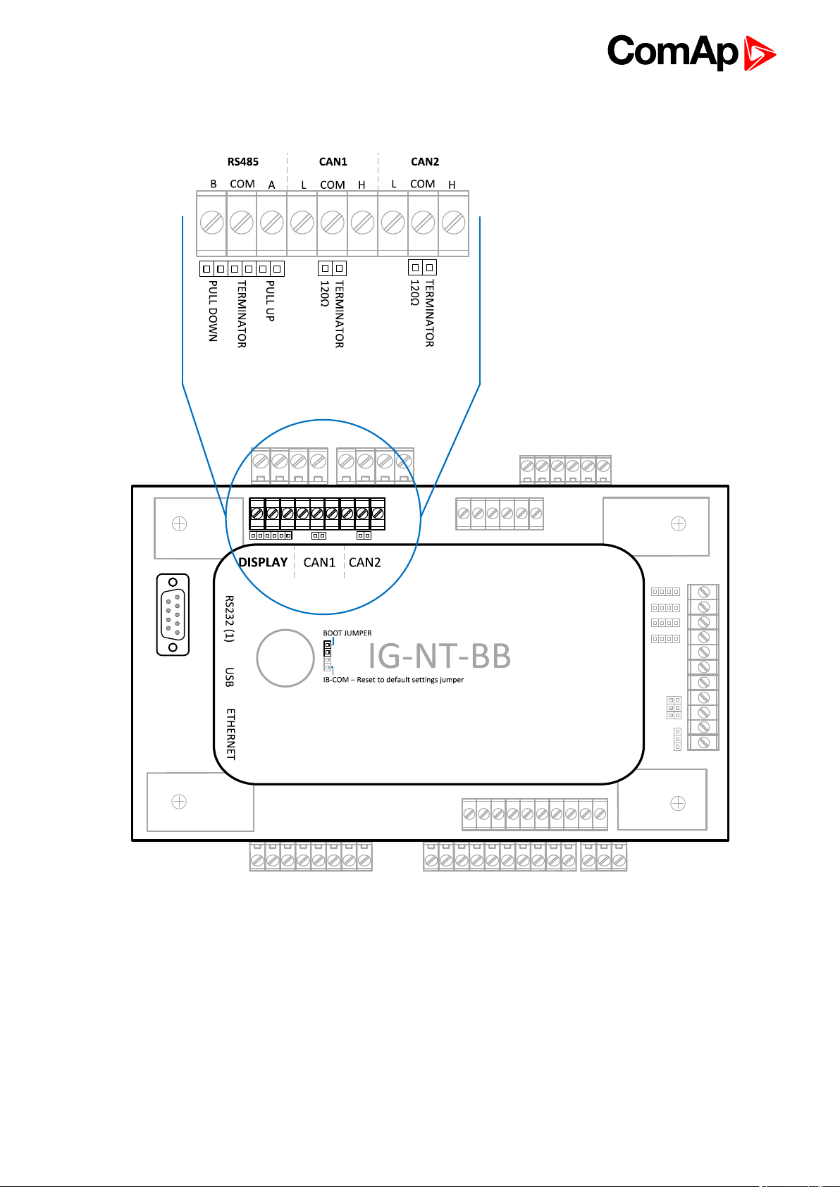
2.5 IG/IM-NT-BB - Communication 16
2.6 IG/IM-NT-BB - Terminal 17
2.7 IG/IM-NT-BB - Peripheral modules 18
2.8 IG/IM-NT-BB - Jumper settings 19
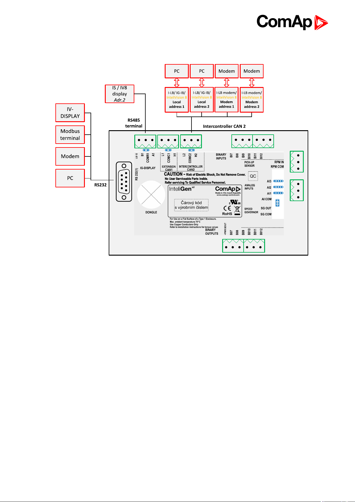
2.9 IG-NT - Communications, Terminals 20
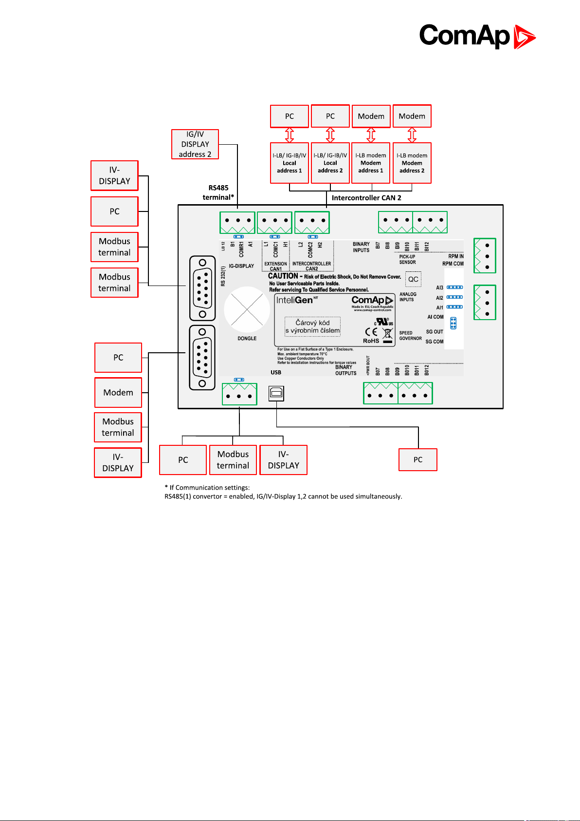
2.10 IG-NTC - Communication, Terminals 21
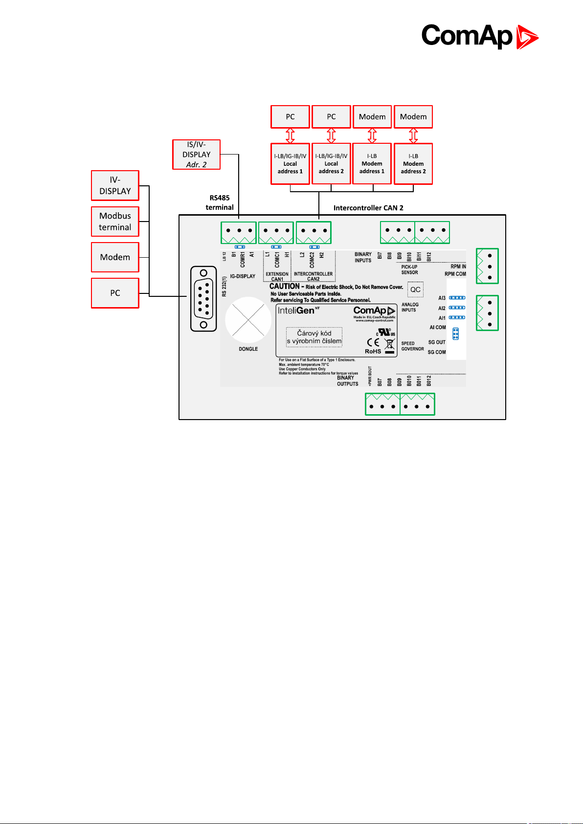
2.11 IM-NT - Communications, Terminals 22
2.12 IS-NT-BB - Communications, Terminals 23
3 Applications overview 24
3.1 Direct PC connection to Single gen-set 24
3.1.1 RS232 connection 24
3.1.2 USB connection 25
3.1.3 RS485 connection 26
3.1.4 Ethernet connection (Direct) 27
3.2 Direct PC connection to Multiple gen-sets 29
3.2.1 RS485 connection 29
3.2.2 RS232/485 connection (I-LB+) 31
3.2.3 USB connection via I-LB+ module 32
3.2.4 Ethernet connection via IB-NT 34
3.2.5 Ethernet connection (Direct) 35
3.3 Monitoring Local on site - MODBUS 36
3.3.1 RS232 ModBus 36
3.3.2 RS485 ModBus 38
3.3.3 Ethernet - MODBUS/TCP (Direct) 39
IGS-NT Communication Guide
2
Page 3

3.4 ModBus - Multiple gen-sets 41
3.4.1 RS485 – MODBUS 41
3.4.2 RS232/RS485 – MODBUS (I-LB+) 42
3.4.3 Ethernet - MODBUS (IB-NT) 43
3.5 Access to password protected objects 45
4 Remote monitoring 47
4.1 Connection to Internet (Direct) 48
4.1.1 Controllers 48
4.1.2 Equipment 49
4.1.3 Available software for IG/IS-NT 49
4.2 Internet connection via AirGate 49
4.3 WebSupervisor 52
4.4 Web interface 53
4.4.1 Scada 54
4.4.2 Measurement 55
4.4.3 Setpoints 56
4.4.4 History 56
4.4.5 Web server adjustment 57
4.5 Internet connection via cellular network 58
4.5.1 Connection via Internet bridge IB-NT 58
4.5.2 Active Call 58
4.6 Active SMS 59
4.6.1 Active E-mail (SMS E-mail) 60
4.7 Access Lock 61
5 Controller setup 62
5.1 Displays 62
5.1.1 InteliVision 12Touch display 62
5.1.2 InteliVision 8 display 63
5.1.3 InteliVision 5 display 64
5.2 Comms extension - I-LB+ Local bridge 64
5.2.1 Jumper setings 66
5.2.2 Jumper selection tree 66
5.3 I-CR Module for CAN Bus Extension 67
5.3.1 I-CR module functions 68
5.3.2 I-CR configuration jumpers 68
5.4 I-CR-R Module for CAN Bus Redundancy 68
5.5 I-CR-R module properties 70
5.5.1 I-CR-R module functions 70
IGS-NT Communication Guide
3
Page 4

5.5.2 I-CR-R configuration jumpers 71
5.5.3 I-CR-R indication and diagnostic LEDs 72
5.6 Commands for IGS-NT 72
5.7 Commands for IM-NT 75
6 Connection 77
6.1 Recommended CAN/RS485 connection 77
6.1.1 CAN bus connection 77
6.1.2 CAN/fiber optic converter 78
6.1.3 CAN-Ethernet gateway 79
6.1.4 RS485 connection 80
6.1.5 Termination Resistors 81
6.1.6 Bias Resistors 81
7 Communication 82
7.1 Communication cables 82
7.1.1 RS 485 cable 82
7.1.2 CAN bus cable 83
7.1.3 RS232 cable 83
7.1.4 Cables for direct and modem connections 83
7.1.5 USB cable 84
7.1.6 Ethernet cable 85
7.2 SMS Message command 85
7.2.1 Controller address 85
7.2.2 Access code 85
7.2.3 Read value or setpoint 86
7.2.4 Adjust setpoint 86
7.2.5 Enter password 86
7.2.6 Gen-set control 87
7.2.7 Read Alarm list 87
7.2.8 Time delay 88
7.2.9 Remote switches (IG/IS-NT only) 88
7.2.10 ExtValues (IG/IS-NT only) 88
7.2.11 Answer message 89
7.2.12 Examples of SMS commands 89
7.3 Modbus Communication 90
7.3.1 Data reading 91
7.3.2 Data writing 91
7.4 Examples of Modbus Communication 93
7.4.1 Battery voltage – reading (read multiple registers) 94
IGS-NT Communication Guide
4
Page 5

7.4.2 Values (Oil press, Water temp, Fuel level) – reading 96
7.4.3 Binary input - reading 97
7.4.4 Password decode - reading 97
7.4.5 Gen-set name - reading 98
7.4.6 Engine state - reading 99
7.4.7 Gear teeth – writing 100
7.4.8 Nominal Power – writing 100
7.4.9 Mode – writing 101
7.4.10 Reset/Confirm Alarm 102
7.4.11 Remote Switch 1-8 – Set (Remote Control 1-8) 103
7.4.12 External Value1 – writing 104
7.4.13 User & Password – in two steps 105
7.4.14 User & Password – in one step 106
7.4.15 Start the engine – in one step 106
7.4.16 Start the engine – in two steps 107
7.4.17 History – reading 107
7.4.18 AlarmList reading 109
7.4.19 Change the communication language (only String type data) 110
7.5 Reserved communication objects 111
7.6 Replacing InternetBridge-NT 113
7.6.1 Sites with "NT" family controllers 113
7.6.2 Sites with new controller families 115
7.6.3 Combined sites 117
8 Converters 119
8.1 Converter RS232 ↔ RS485 119
8.1.1 General properties of RS232 to RS485 converters: 119
8.1.2 Recommended converters 120
8.2 RS232 Bluetooth adapter 120
8.2.1 Recommended adapter 120
8.3 Converter USB ↔ RS232 120
8.3.1 Recommended converters 121
8.4 Converter USB ↔ RS485 121
8.4.1 Recommended converter 121
8.5 Converter CAN ↔ CAN 122
8.5.1 Recommended converter 122
8.6 Recommended optical USB extension cables 122
8.6.1 Radio Link 122
8.6.2 Recommended equipment 123
8.7 Converter Modbus RTU ↔ Profibus 123
IGS-NT Communication Guide
5
Page 6

8.7.1 GE Digital Energy - P485 Modbus to Profibus Converter 123
8.7.2 Converter settings 123
8.7.3 Setup example (using wizard) 124
8.7.4 Controller settings 127
8.8 Anybus Comunicator 128
8.8.1 Ethernet converter from twisted pair(UTP/STP) to optic 128
8.8.2 Recommended equipment 128
9 Modbus Connection 129
9.1 Modbus Step by Step 129
9.2 Important setpointsin the controller 129
9.2.1 Modbus communication via RS232 – single controller 130
9.2.2 Modbus communication viaRS485 130
9.2.3 Modbus communication via RS485 – multiple controllers 131
9.2.4 Modbus communicationviaI-LB+ 131
9.2.5 Modbus communicationvia IB-NT 132
9.3 Modbus Protocol Description 132
9.3.1 Modbus TCP 132
9.3.2 Modbus RTU 135
9.3.3 Alarm list reading 139
9.3.4 History reading 143
9.4 Check field calculation 143
9.5 How get numbers of Modbus communication objects 143
9.6 User Modbus 144
10 Modbus Appendix 146
10.1 Modbus Switches 146
10.2 Data types 146
10.3 Communication status 148
10.4 Error list 150
IGS-NT Communication Guide
6
Page 7

1 Document information
1.1 Clarification of notation 7
1.2 About this guide 7
1.3 Legal notice 7
1.4 Document history 9
1.5 Definition of terms 9
1.1 Clarification of notation
Note: This type of paragraph calls readers attention to a notice or related theme.
IMPORTANT: This type of paragraph highlights a procedure, adjustment etc., which can cause a
damage or improper function of the equipment if not performed correctly and may not be clear at
first sight.
Example: This type of paragraph contains information that is used to illustrate how a specific function
works.
1.2 About this guide
There are following types of communication between controller(s) and superior system in the controller:
Local (on site) communication
via ComAp software
via MODBUS (MODBUS RTU or MODBUS TCP)
Remote communication
via Ethernet
via Internet (AirGate)
via MODEM
These types of connections are available via RS232, RS485, USB, ETHERNET communication ports.
1.3 Legal notice
This End User's Guide/Manual as part of the Documentation is an inseparable part of ComAp’s Product and
may be used exclusively according to the conditions defined in the “END USER or Distributor LICENSE
AGREEMENT CONDITIONS – COMAP CONTROL SYSTEMS SOFTWARE” (License Agreement) and/or in
the “ComAp a.s. Global terms and conditions for sale of Products and provision of Services” (Terms) and/or in
the “Standardní podmínky projektů komplexního řešení ke smlouvě o dílo, Standard Conditions for Supply of
Complete Solutions” (Conditions) as applicable.
ComAp’s License Agreement is governed by the Czech Civil Code 89/2012 Col., by the Authorship Act
121/2000 Col., by international treaties and by other relevant legal documents regulating protection of the
intellectual properties (TRIPS).
IGS-NT Communication Guide
7
Page 8

The End User and/or ComAp’s Distributor shall only be permitted to use this End User's Guide/Manual with
ComAp Control System Registered Products. The Documentation is not intended and applicable for any other
purpose.
Official version of the ComAp’s End User's Guide/Manual is the version published in English. ComAp reserves
the right to update this End User's Guide/Manual at any time. ComAp does not assume any responsibility for its
use outside of the scope of the Terms or the Conditions and the License Agreement.
Licensed End User is entitled to make only necessary number of copies of the End User's Guide/Manual. Any
translation of this End User's Guide/Manual without the prior written consent of ComAp is expressly prohibited!
Even if the prior written consent from ComAp is acquired, ComAp does not take any responsibility for the
content, trustworthiness and quality of any such translation. ComAp will deem a translation equal to this End
User's Guide/Manual only if it agrees to verify such translation. The terms and conditions of such verification
must be agreed in the written form and in advance.
For more details relating to the Ownership, Extent of Permitted Reproductions Term of Use of the
Documentation and to the Confidentiality rules please review and comply with the ComAp’s License
Agreement, Terms and Conditions available on www.comap-control.com.
Security Risk Disclaimer
Pay attention to the following recommendations and measures to increase the level of security of ComAp
products and services.
Please note that possible cyber-attacks cannot be fully avoided by the below mentioned recommendations and
set of measures already performed by ComAp, but by following them the cyber-attacks can be considerably
reduced and thereby to reduce the risk of damage. ComAp does not take any responsibility for the actions of
persons responsible for cyber-attacks, nor for any damage caused by the cyber-attack. However, ComAp is
prepared to provide technical support to resolve problems arising from such actions, including but not limited to
restoring settings prior to the cyber-attacks, backing up data, recommending other preventive measures against
any further attacks.
Warning: Some forms of technical support may be provided against payment. There is no legal or factual
entitlement for technical services provided in connection to resolving problems arising from cyber-attack or
other unauthorized accesses to ComAp's Products or Services.
General security recommendations and set of measures
1. AccessCode
• Change the AccessCode BEFORE the device is connected to a network.
• Use a secure AccessCode – ideally a random string of 8 characters containing lowercase, uppercase letters
and digits.
• For each device use a different AccessCode.
2. Password
• Change the password BEFORE the device enters a regular operation.
• Do not leave displays or PC tools unattended if an user, especially administrator, is logged in.
3. Controller Web interface
• The controller web interface at port TCP/80 is based on http, not https, and thus it is intended to be used only
in closed private network infrastructures.
• Avoid exposing the port TCP/80 to the public Internet.
4. MODBUS/TCP
• The MODBUS/TCP protocol (port TCP/502) is an instrumentation protocol designed to exchange data
between locally connected devices like sensors, I/O modules, controllers etc. From it’s nature it does not
IGS-NT Communication Guide
8
Page 9
contain any kind of security – neither encryption nor authentication. Thus it is intended to be used only in closed
private network infrastructures.
• Avoid exposing the port TCP/502 to the public Internet.
5. SNMP
• The SNMP protocol (port UDP/161) version 1,2 is not encrypted. Thus it is intended to be used only in closed
private network infrastructures.
• Avoid exposing the port UDP/161 to the public Internet.
1.4 Document history
Revision number Date Author
1 Jan Tomandl
1.5 Definition of terms
Local connection
Type of connection using direct connection on site via protocol of ports on the controller. Length of
connection is given by protocol specification.
Remote connection
Type of connection using standard communication lines such as Internet, modem connection and GSM
connection for communication between controller and other superior device.
Comap Protocol
Communication between PC with ComAp software (InteliMonitor, GenConfig) and controller is running
on this protocol.
3rdparty software
Software using standardized protocol for sharing of data between particular systems (for example
Modbus RTU, Modbus TCP etc.).
Single gen-set communication
This type of connection allows communication only with one controller. Communication with other
controllers on site via this type of connection is not possible.
Multiple gen-set communication
This type of connection allows communication with more than one controller on site via single
communication link.
Monitoring
Type of communication used for continuous displaying of process data and process control of the
system.
Configuration
Type of communication used for writing of configuration file into the controller.
Note: There are used some abbreviations for resolution of all hardware variations of IGS -NT controllers in this
document. These abbreviations correspond with order codes of each HW variation (see the table below).
IGS-NT Communication Guide
9
Page 10

InteliSys NTC Basebox IS-NTC-BB
InteliSys NT IS-NT-BB
InteliGen NTC Basebox IG-NTS-BB
InteliGen NT Basebox IG-NT-BB
InteliGen NTC IG-NTC
InteliGen NT IG-NT
InteliMains NTC Basebox IM-NTC-BB
InteliMains NT Basebox IM-NT-BB
InteliMains NT IM-NT
Note: In abbreviation the “C” means “Communications” – controller with extended communication ports. The
“Basebox” controller has not inbuilt LCD panel, it is recommended to use IV5, IV8 or IV12 remote display.
Abbreviation “IGS-NT” stands for IG-NT or IS-NT and it is used to describe common features of both products.
IGS-NT Communication Guide
10
Page 11

2 Controllers communication capabilities
2.1 IG/IS/IM-NTC-BB - Communications 12
2.2 IG/IS/IM-NTC-BB - Terminals 13
2.3 IG/IS/IM-NTC-BB - Peripheral modules 14
2.4 IG/IS/IM-NTC-BB - Jumpers settings 15
2.5 IG/IM-NT-BB - Communication 16
2.6 IG/IM-NT-BB - Terminal 17
2.7 IG/IM-NT-BB - Peripheral modules 18
2.8 IG/IM-NT-BB - Jumper settings 19
2.9 IG-NT - Communications, Terminals 20
2.10 IG-NTC - Communication, Terminals 21
2.11 IM-NT - Communications, Terminals 22
2.12 IS-NT-BB - Communications, Terminals 23
6 back to Table of contents
IGS-NT Communication Guide
11
Page 12
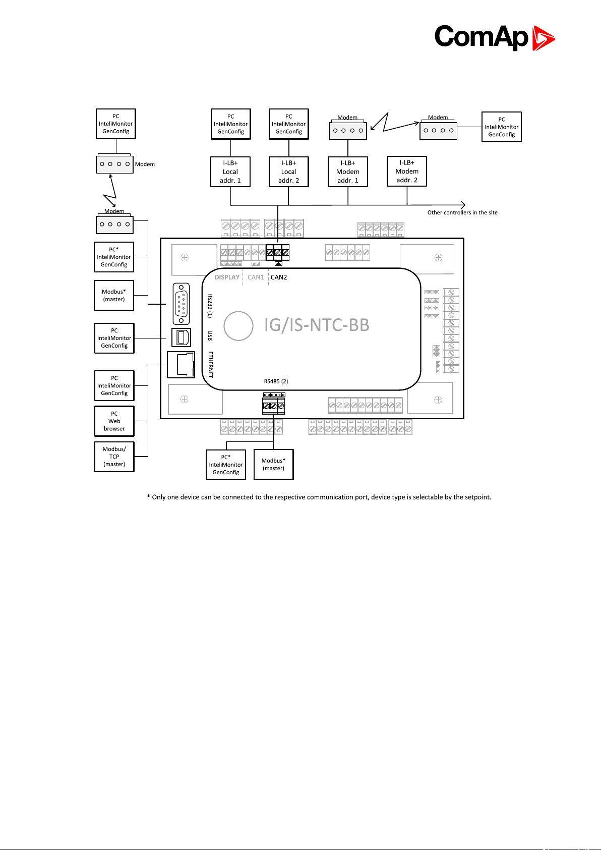
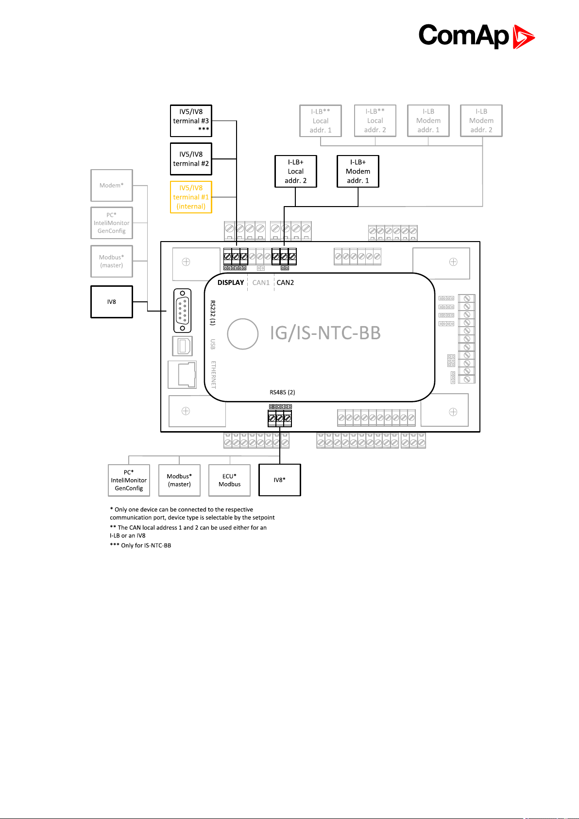
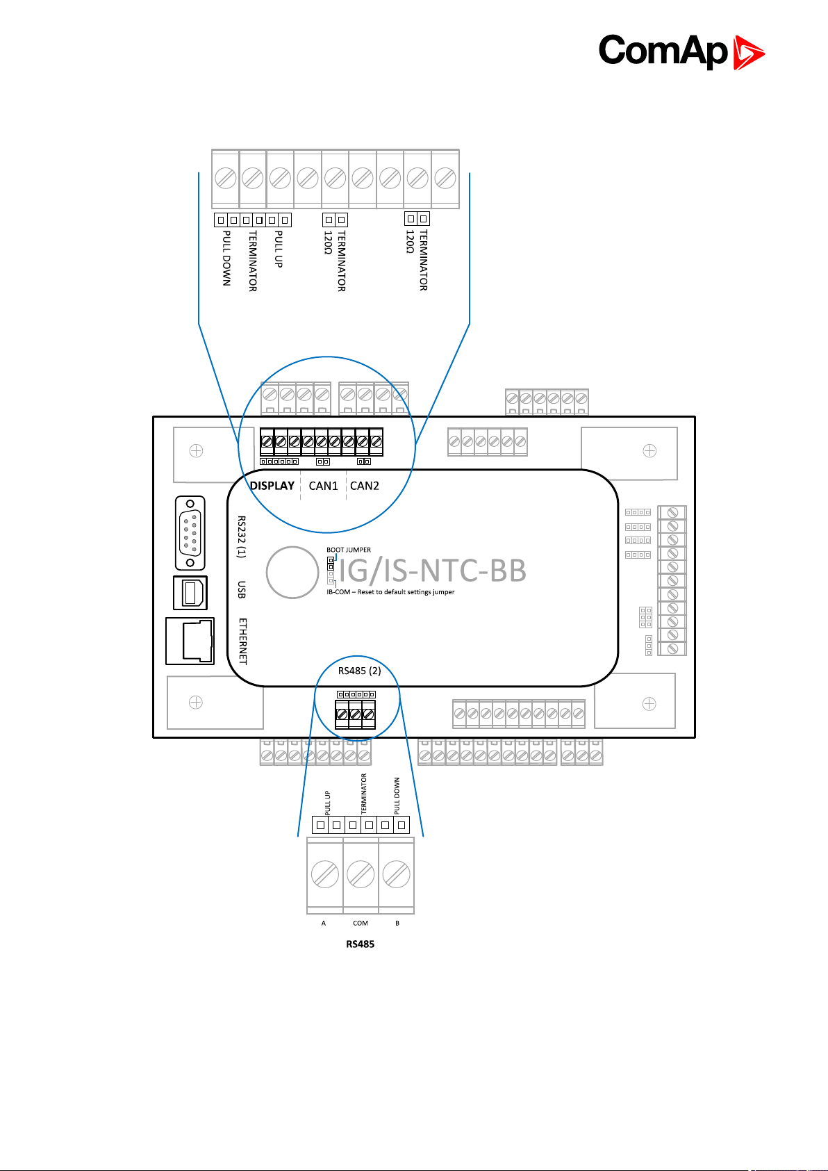
2.1 IG/IS/IM-NTC-BB - Communications
IGS-NT Communication Guide
12
Page 13
2.2 IG/IS/IM-NTC-BB - Terminals
IGS-NT Communication Guide
13
Page 14
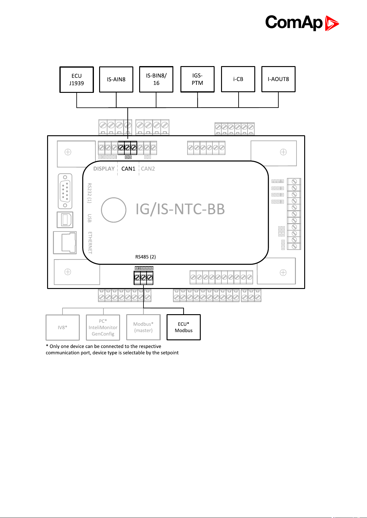
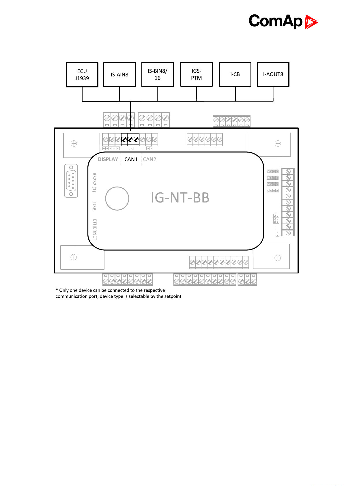
2.3 IG/IS/IM-NTC-BB - Peripheral modules
IGS-NT Communication Guide
14
Page 15
2.4 IG/IS/IM-NTC-BB - Jumpers settings
IGS-NT Communication Guide
15
Page 16
2.5 IG/IM-NT-BB - Communication
IGS-NT Communication Guide
16
Page 17
2.6 IG/IM-NT-BB - Terminal
IGS-NT Communication Guide
17
Page 18
2.7 IG/IM-NT-BB - Peripheral modules
IGS-NT Communication Guide
18
Page 19
2.8 IG/IM-NT-BB - Jumper settings
IGS-NT Communication Guide
19
Page 20
2.9 IG-NT - Communications, Terminals
IGS-NT Communication Guide
20
Page 21
2.10 IG-NTC - Communication, Terminals
6 back to Controllers communication capabilities
IGS-NT Communication Guide
21
Page 22
2.11 IM-NT - Communications, Terminals
IGS-NT Communication Guide
22
Page 23
2.12 IS-NT-BB - Communications, Terminals
IGS-NT Communication Guide
23
Page 24

3 Applications overview
3.1 Direct PC connection to Single gen-set 24
3.2 Direct PC connection to Multiple gen-sets 29
3.3 Monitoring Local on site - MODBUS 36
3.4 ModBus - Multiple gen-sets 41
3.5 Access to password protected objects 45
6 back to Table of contents
3.1 Direct PC connection to Single gen-set
3.1.1 RS232 connection
Controllers
Controllers IG-NT-BB IM-NT-BB IG-NTC-BB IS-NTC-BB IM-NTC-BB
Connection
applicable
Available
ports
More info
Controllers IG-NT IG-NTC IS-NT-BB IM-NT
Connection
applicable
Available
ports
More info
YES YES YES YES YES
RS232(1) RS232(1) RS232(1) RS232(1) RS232(1)
IG/IM-NT-BB - Communication
(page 16)
YES YES YES YES
RS232(1)
IG-NT -
Communications,
Terminals (page 20)
RS232(1)
RS232(2)
IG-NTC -
Communication,
Terminals (page
21)
IG/IS/IM-NTC-BB - Communications (page 12)
RS232(1)
RS232(2)
IS-NT-BB -
Communications,
Terminals (page 23)
RS232(1)
IM-NT -
Communications,
Terminals (page 22)
Note: Other way how to realize RS232 connection is via RS232/485 connection (I-LB+) (page 31).
IGS-NT Communication Guide
24
Page 25
Controller setup
(Setpoints/Comms settings group)
RS232(1) mode = DIRECT
RS485(1) conv. = DISABLED
Equipment
Controller side -
Connection RS232 cable (page 83) up to 10m
PC side RS232 connection or RS232/USB converter
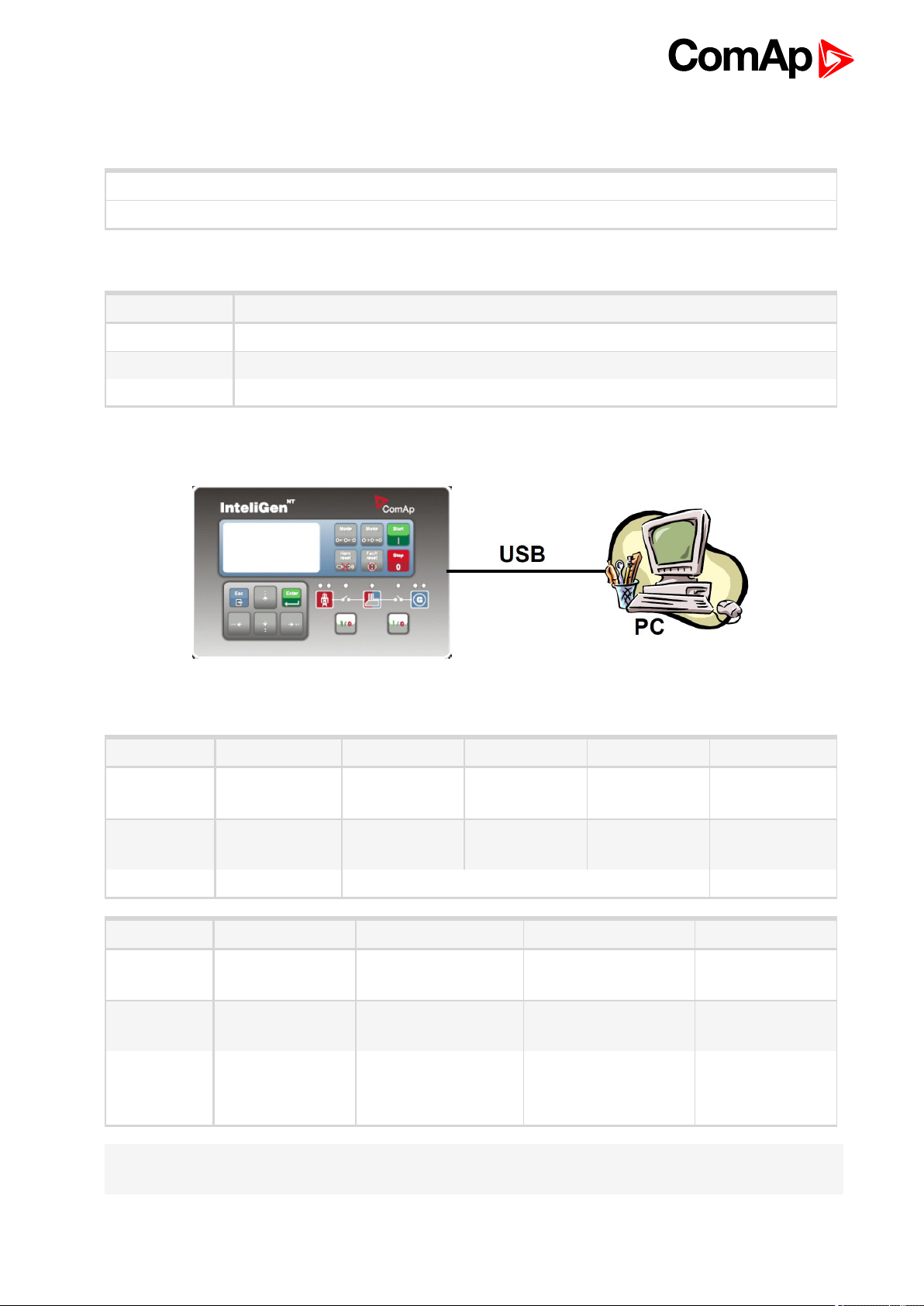
3.1.2 USB connection
Equipment needed
Controllers
Controllers IG-NT-BB IG-NTC-BB IS-NTC-BB IM-NTC-BB IM-NT-BB
Connection
applicable
Available
ports
More info IG/IS/IM-NTC-BB - Communications (page 12)
Controllers IG-NT IG-NTC IS-NT-BB IM-NT
Connection
applicable
Available
ports
More info
Note: Direct USB connection is not possible for some controllers, however USB connection is available for all
mentioned controllers via RS232/485 connection (I-LB+) (page 31).
NO YES YES YES NO
external bridge USB USB USB external bridge
NO YES YES NO
external bridge(1) USB USB external bridge
IG-NTC -
Communication,
Terminals (page 21)
IS-NT-BB -
Communications,
Terminals (page 23)
IGS-NT Communication Guide
25
Page 26
Controller setup
(Setpoints/Comms settings group)
Equipment
Controller side -
Connection USB cable (page 84) A-B
PC side USB connection
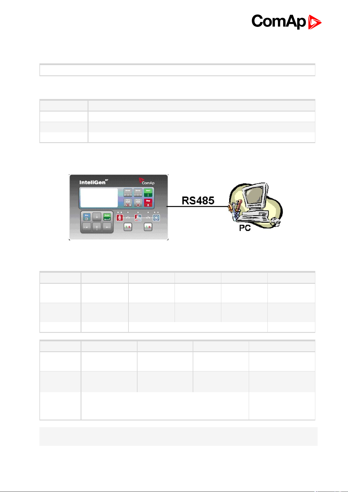
3.1.3 RS485 connection
No special settings are required
Equipment needed
Controllers
Controllers IG-NT-BB IG-NTC-BB IS-NTC-BB IM-NTC-BB IM-NT-BB
Connection
applicable
Available
ports
More info IG/IS/IM-NTC-BB - Communications (page 12)
Controllers IG-NT IG-NTC IM-NT IS-NT-BB
Connection
applicable
Available
ports
More info IG-NTC - Communication, Terminals (page 21)
NO YES YES YES NO
external bridge RS485(2) RS485(2) RS485(2) external bridge
NO YES NO YES
RS485(1)
RS485(1)
RS485(1) RS485(2)
RS485(2)
IS-NT-BB -
Communications,
Terminals (page 23)
Note: Direct RS485 connection is not possible for some controllers, however RS485 connection is available for
all mentioned controllers via RS232/485 connection (I-LB+) (page 31).
IGS-NT Communication Guide
26
Page 27
Controller setup
(Setpoints/Comms settings group)
RS232(2) mode = DIRECT
RS485(2) conv. = ENABLED
Equipment
Equipment needed
Controller side -
Connection RS 485 cable (page 82) - Twisted pair, length up to 1 km
PC side Converter RS485/RS232 or USB
Note: RS485 connection can be used for gen-set control for longer distance. IG-NT-BB has no possibility of
direct connection to RS485 bus. This controller provides RS232 port only. External converter from RS232 to
RS485 is needed.
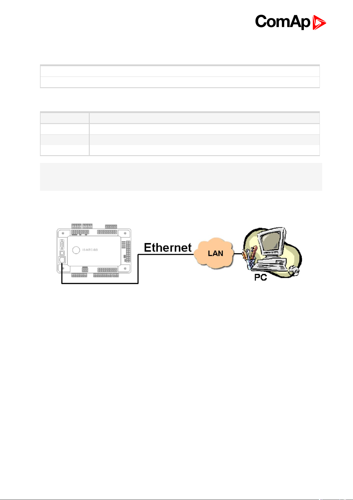
3.1.4 Ethernet connection (Direct)
The Internet (Ethernet) connection is a point-to-point connection between a PC and a controller or site via an
TCP/IP protocol-based network. The physical configuration of such network can be a small local area ethernet
network as well as the Internet.
IGS-NT Communication Guide
27
Page 28
Controllers
Controllers IG-NT-BB IG-NTC-BB IS-NTC-BB IM-NTC-BB IM-NT-BB
Connection
applicable
Available
ports
More info IG/IS/IM-NTC-BB - Communications (page 12)
Controllers IG-NT IG-NTC IS-NT-BB IM-NT
Connection
applicable
Available
ports
Note: Ethernet connection is available for all mentioned controllers via external bridge or IB-NT (see Ethernet
connection via IB-NT on page 34).
Number of clients connected simultaneously
2 clients with InteliMonitor or WebSupervisor (Comap/TCP protocol)
2 clients with web interface
Using a web browser
NO YES YES YES NO
external bridge ETHERNET ETHERNET ETHERNET external bridge
NO NO NO NO
external bridge external bridge external bridge external bridge
Ethernet connection to controller makes possible using any web browser for basic monitoring and adjustment of
the controller. Simply put the IP address of the module into the address line in your web browser like
http://192.168.1.254 and then enter access code. In case of connection from web browser there is 5 minutes
timeout after closing the browser window. After that the client is automatically logged out.
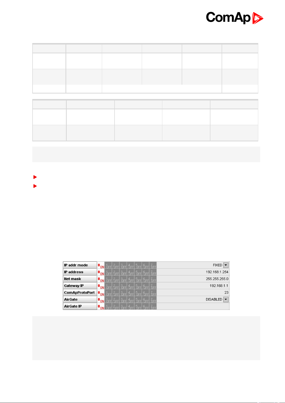
Ethernet connection settings
Parameters can be set via any type of connection (USB, RS232, Ethernet). Setup is provided via InteliMonitor.
For Ethernet connection set these parameters in Comms Settings group:
Note: The IP addresses of the controllers must be accessible from the remote computer. If the remote
computer is connected into another LAN segment than the gen-sets are, there must be a gateway(s) that enable
direct traffic between the segments. If the remote computer is connected via Internet, then the internet gateway
of the LAN where gen-sets are connected must have public IP address, must allow incoming traffic and must
provide port forwarding from the external public IP to the different internal gen-set IPs according to the port
used.
IGS-NT Communication Guide
28
Page 29
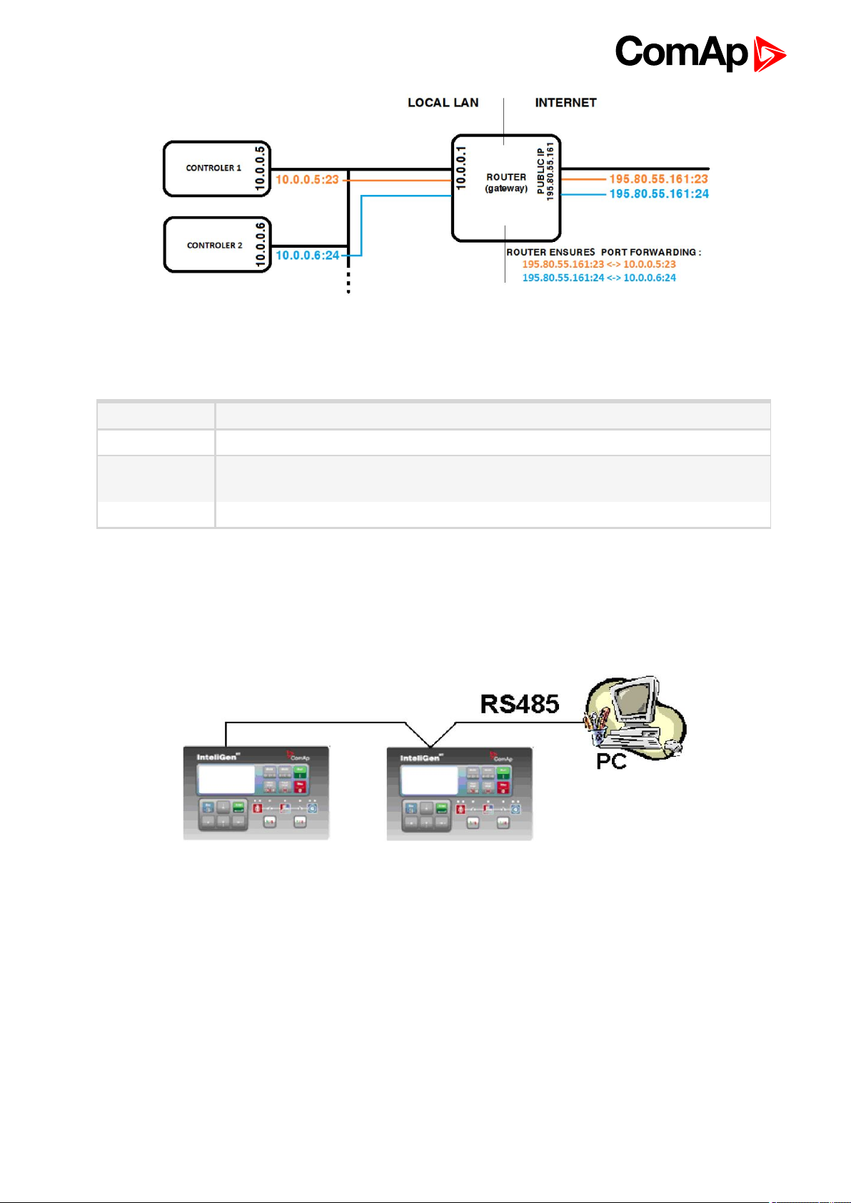
Image 3.1 Internet gateway configuration example (port forwarding)
Equipment
Controllerside -
Equipment needed
Connection
PCside ETHERNET connection
Ethernet cable (page 85) to LAN, for point to point connection between PC and
controller use cross-wired cable
3.2 Direct PC connection to Multiple gen-sets
3.2.1 RS485 connection
IGS-NT Communication Guide
29
Page 30

Controllers
Controllers IG-NT-BB IG-NTC-BB IS-NTC-BB IM-NTC-BB IM-NT-BB
Connection
applicable
Available
ports
More info IG/IS/IM-NTC-BB - Communications (page 12)
Controllers IG-NT IG-NTC IM-NT IS-NTC-BB
Connection
applicable
Available
ports
More info
NO YES YES YES NO
- RS232(2) RS232(2) RS232(2) -
YES YES YES YES
RS232(1)
IG-NT -
Communications,
Terminals (page 20)
RS232(1)
RS232(1) RS232(2)
RS232(2)
IG-NTC - Communication, Terminals
(page 21)
Communications,
Terminals (page 23)
IS-NT-BB -
Controller setup
(Setpoints/Comms settings group)
RS232(2) mode = DIRECT
RS485(2) conv. = ENABLED
Note: IG-NT-BB has no possibility of direct connection to RS485 bus. This controller provides RS232 port only.
External converter from RS232 to RS485 is needed.
Equipment
Equipment needed
Controller side -
Connection RS 485 cable (page 82) - Twisted pair, length up to 1 km
PC side RS232 connection, Converter RS485/RS232
IGS-NT Communication Guide
30
Page 31

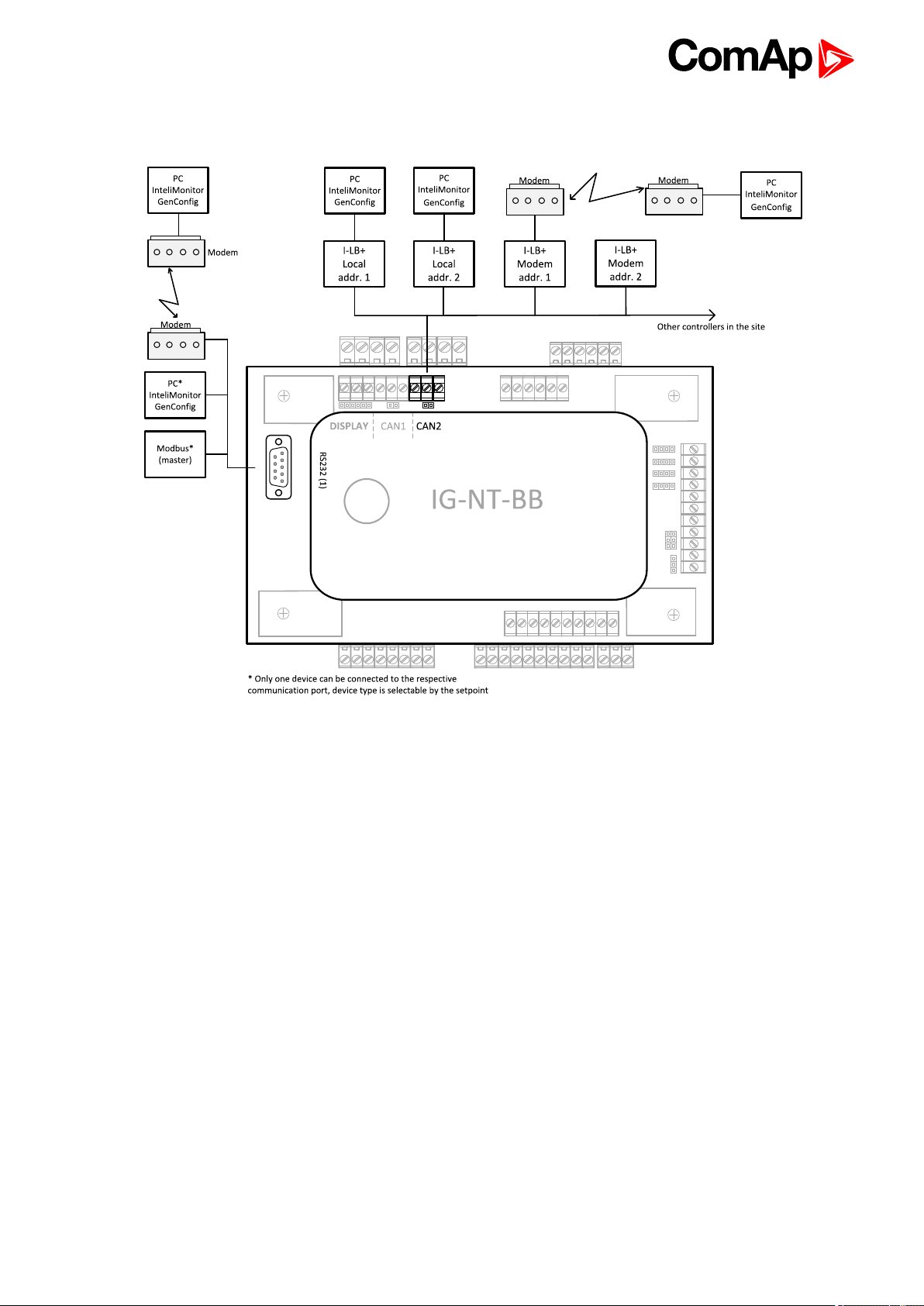
3.2.2 RS232/485 connection (I-LB+)
Note: Comms extension - I-LB+ Local bridge (page 64) enables monitoring and configuration up to 32
controllers interconnected via CAN(2) intercontroller bus. It is also possible to use I-LB+ for single controller
connection.
I-LB+ hardware setup
(all jumpers in those positions)
HW/SW control No matter
ComAp/ModBus
ADDR1/ADDR2
DIRECT/MODEM Open
RS485/RS232 Selection of communication port (jumper is in RS232 or RS485 position)
Comm. speed. No matter
RS485 120 Ohm Open = terminator not connected, Close = terminator connected
CAN 120 Ohm Open = terminator not connected, Close = terminator connected
Open
Selection of CAN address. Open = ADDR1, Close = ADDR2
It is possible to use up to two I-LB+ devices in direct mode on CAN(2) bus. Let jumper
open in case of using one I-LB+ module. Other I-LB module has to have this jumper
closed. (read more about Comms extension - I-LB+ Local bridge (page 64))
IGS-NT Communication Guide
31
Page 32

Controllers
Controllers IG-NT-BB IG-NTC-BB IS-NTC-BB IM-NT-BB IM-NTC-BB
Connectionapplicable YES YES YES YES YES
Available ports
More info
RS232 on ILB+
RS485 on ILB+
RS232 on ILB+
RS485 on ILB+
Comms extension - I-LB+ Local bridge (page 64)
RS232 on ILB+
RS485 on ILB+
RS232 on ILB+
RS485 on ILB+
RS232 on ILB+
RS485 on ILB+
Controllers IG-NT IG-NTC IS-NT-BB IM-NT
Connectionapplicable YES YES YES YES
Availableports
RS232 on I-LB+
RS485 on I-LB+
RS232 on I-LB+
RS485 on I-LB+
RS232 on I-LB+
RS485 on I-LB+
RS232 on I-LB+
RS485 on I-LB+
More info Comms extension - I-LB+ Local bridge (page 64)
Equipment
Equipment needed
Controller side I-LB+ unit (see Comms extension - I-LB+ Local bridge on page 64)
Connection RS232 cable (page 83) or RS 485 cable (page 82)
PC side
RS232 connection or RS232/USB converter
RS485 connection or RS485/USB converter
3.2.3 USB connection via I-LB+ module
Note: Comms extension - I-LB+ Local bridge (page 64) enables monitoring and configuration up to 32
controllers interconnected via CAN(2) intercontroller bus. It is also possible to use I-LB+ for single controller
connection.
IGS-NT Communication Guide
32
Page 33

I-LB+ hardware setup
(all jumpers in those positions)
HW/SW control no matter (Open)
ComAp/ModBus Open
ADDR1/ADDR2
DIRECT/MODEM Open
RS485/RS232 No matter
Comm. speed. No matter
RS485 120 Ohm Open = terminator not connected, Close = terminator connected
CAN 120 Ohm Open = terminator not connected, Close = terminator connected
Selection of CAN address. Open = ADDR2, Close = ADDR1 (read more about I-LB+
module)
Controllers
Controllers IG-NT-BB IG-NTC-BB IS-NTC-BB IM-NT-BB IM-NTC-BB
Connectionapplicable YES YES YES YES YES
Available ports USB on I-LB+ USB on I-LB+ USB on I-LB+ USB on I-LB+ USB on I-LB+
More info Comms extension - I-LB+ Local bridge (page 64)
Controllers IG-NT IG-NTC IS-NT-BB IM-NT
Connectionapplicable YES YES YES YES
Available ports USB on I-LB+ USB on I-LB+ USB on I-LB+ USB on I-LB+
More info Comms extension - I-LB+ Local bridge (page 64)
Equipment
Equipment needed
Controller side I-LB+ unit (see Comms extension - I-LB+ Local bridge on page 64)
Connection USB (see USB cable on page 84)
PC side USB connection
IGS-NT Communication Guide
33
Page 34

3.2.4 Ethernet connection via IB-NT
Up to 32 controllers can be monitored via one IB-NT. Response time of a system with this type of connection
depends on number of controllers, higher number of controllers means slower system response time.
Controllers
Controllers IG-NT-BB IG-NTC-BB IS-NTC-BB IM-NT-BB IM-NTC-BB
Connection
applicable
Available
ports
More info I-CR Module for CAN Bus Extension (page 67)
Controllers IG-NT IG-NTC IS-NT-BB IM-NT
Connection
applicable
Available
ports
More info I-CR Module for CAN Bus Extension (page 67)
Note: Max. 3 clients of ComAp type (InteliDDE server, WinScope, WebSupervisor) can be connected
simultaneously to the IB-NT.
Note: For more information about IB-NT internet bridge read IB-NT Global Guide.
YES YES YES YES YES
IB-NT IB-NT IB-NT IB-NT IB-NT
YES YES YES YES
IB-NT IB-NT IB-NT IB-NT
IGS-NT Communication Guide
34
Page 35

3.2.5 Ethernet connection (Direct)
Controllers
Controllers IG-NT-BB IG-NTC IS-NTC-BB IM-NTC-BB IM-NT-BB
Connection
applicable
Available
ports
More info IG/IS/IM-NTC-BB - Communications (page 12)
Controllers IG-NT IG-NTC IS-NT-BB IM-NT
Connection
applicable
Available
ports
Note: Ethernet connection is available for all mentioned controllers via external internet bridge or IB-NT (see
Ethernet connection via IB-NT on page 34).
Number of clients connected simultaneously
2 clients with InteliMonitor or Web Server (Comap/TCP protocol)
2 clients with web interface
Ethernet connection settings
NO YES YES YES NO
external bridge ETHERNET ETHERNET ETHERNET external bridge
NO NO NO NO
external bridge external bridge external bridge external bridge
Perform the connection settings the same way as for Ethernet connection (Direct) (page 27).
Note: The IP addresses of the controllers must be accessible from the remote computer. If the remote
computer is connected into another LAN segment than the gen-sets are, there must be a gateway(s) that enable
direct traffic between the segments. If the remote computer is connected via Internet, then the internet gateway
of the LAN where gen-sets are connected must have public IP address, must allow incoming traffic and must
provide port forwarding from the external public IP to the different internal gen-set IPs according to the port
used.
IGS-NT Communication Guide
35
Page 36

Image 3.2 Internet gateway configuration example (port forwarding)
Equipment
Controllerside -
Equipment needed
Connection
PC side ETHERNET connection
Ethernet cable (page 85) to LAN, for point to point connection between PC and
controller use cross-wired cable
3.3 Monitoring Local on site - MODBUS
3.3.1 RS232 ModBus
IGS-NT Communication Guide
36
Page 37

Controllers
Controllers IG-NT-BB IM-NT-BB IG-NTC-BB IS-NTC-BB IM-NTC-BB
Connection
applicable
Available
ports
More info
Controllers IG-NT-BB IG-NTC IS-NT-BB IM-NT
Connection
applicable
Available
ports
More info
Note: Other way how to realize RS232 connection is via RS232/RS485 – MODBUS (I-LB+) (page 42).
YES YES YES YES YES
RS232(1) RS232(1) RS232(1) RS232(1) RS232(1)
IG/IM-NT-BB - Communication
(page 16)
YES YES YES YES
RS232(1)
IG-NT -
Communications,
Terminals (page 20)
RS232(1)
RS232(2)
IG-NTC -
Communication,
Terminals (page
21)
IG/IS/IM-NTC-BB - Communications (page 12)
RS232(1)
RS232(2)
IS-NT-BB -
Communications,
Terminals (page 23)
RS232(1)
IM-NT -
Communications,
Terminals (page 22)
Controller setup
(Setpoints/Comms settings group)
RS232(1 or 2) mode = MODBUS-DIRECT
RS485(1 or 2) conv. = DISABLED
RS232(1)MBCSpd = 9600, 19200, 38400, 57600
Equipment
Equipment needed
Controller side -
Connection RS232 cable (page 83) cable up to 10 m
Other device
side
RS232 connection or RS232/USB converter
IGS-NT Communication Guide
37
Page 38

3.3.2 RS485 ModBus
Controllers
Controllers IG-NT-BB IG-NTC-BB IS-NTC-BB IM-NTC-BB IM-NT-BB
Connection
applicable
Available
ports
More info IG/IS/IM-NTC-BB - Communications (page 12)
Controllers IG-NT IM-NT IG-NTC IS-NT-BB
Connection
applicable
Available
ports
More info
Note: Some controllers do not allowe direct RS485 connection, however RS485 connection is available for all
mentioned controllers via RS232/RS485 – MODBUS (I-LB+) (page 42).
NO YES YES YES NO
external bridge RS232(2) RS232(2) RS232(2) external bridge
YES YES YES YES
RS232(1) RS232(1)
IG-NT - Communications, Terminals
(page 20)
RS232(1)
RS232(2)
IG-NTC -
Communication,
Terminals (page 21)
RS232(2)
IS-NT-BB -
Communications,
Terminals (page 23)
Controller setup
(Setpoints/Comms settings group)
RS232(2)MBCSpd = 9600, 19200, 38400, 57600
IGS-NT Communication Guide
RS232(2) mode = MODBUS-DIRECT
RS485(2) conv. = ENABLED
38
Page 39

Equipment
Controller side -
Connection RS 485 cable (page 82)
Equipment needed
Other device
side
RS485 connection or RS485/USB converter
3.3.3 Ethernet - MODBUS/TCP (Direct)
Controllers
Controllers IG-NT-BB IG-NTC-BB IS-NTC-BB IM-NTC-BB IM-NT-BB
Connection
applicable
Available
ports
NO YES YES YES NO
external bridge ETHERNET ETHERNET ETHERNET external bridge
More info IG/IS/IM-NTC-BB - Communications (page 12)
Controllers IG-NT IG-NTC IS-NT-BB IM-NT
Connection
applicable
Available
ports
Note: The communication port for Modbus TCP is 502.
Note: Ethernet Modbus/TCP connection is available for all mentioned controllers via Ethernet - MODBUS (IB-
NT) (page 43).
Number of clients connected simultaneously
1 client ModBus TCP/IP
Ethernet connection settings
Perform the connection settings the same way as for Ethernet connection (Direct) (page 27).
NO NO NO NO
external bridge external bridge external bridge external bridge
IGS-NT Communication Guide
39
Page 40

Modbus/TCP access code
Every Modbus/TCP session has to be started with writing the access code from the modbus/tcp client to the
controller. If the session is closed and reopened again the access code must be written again. The session can
be closed by the client or the controller closes the session automatically if there is no activity from the client
side for 15s.
There are new dedicated registers for entering the AccessCode via Modbus/TCP.
The register numbers are 46339-46346 (register address 6338-6345).
The previous method using register address 24535 remains working as well.
Example of the Modbus message is following (in HEX):
01 10 18 C2 00 08 10 30 00 00 00 00 00 00 00 00 00 00 00 00 00 00 00 FE F3
01 Controller address
10 Modbus function (16dec – Write multiple registers)
18C2 Register address (18C2hex = 6338dec = register 46339)
0008 Number of registers
10 Length of the data (Number of registers x 2B)
30000000... Access code string (16 chars, null-terminated, ASCII, here “0”)
FEF3 CRC
Some devices do not support the modbus function 16. In this case can be the access code writen in controller
as one register No. 46339 using the function 6. The access code has to be the number in the range 0 to 65535.
Equipment
Equipment needed
Controllerside -
Connection
PC side ETHERNET connection
For more informations about ModBus implementation to ComAp controllers see Modbus Communication on
page 90.
Ethernet cable (page 85) to LAN, for point to point connection between PC and
controller use cross-wired cable
IGS-NT Communication Guide
40
Page 41

3.4 ModBus - Multiple gen-sets
3.4.1 RS485 – MODBUS
Controllers
Controllers IG-NT-BB IG-NTC-BB IS-NTC-BB IM-NTC-BB IM-NT-BB
Connection
applicable
Available
ports
More info IG/IS/IM-NTC-BB - Communications (page 12)
Controllers IG-NT IG-NTC IS-NT-BB IM-NT
Connection
applicable
Available
ports
More info
NO YES YES YES NO
- RS485(2) RS485(2) RS485(2) -
NO YES YES NO
RS232(1)
IG-NT -
Communications,
Terminals (page 20)
RS232(1)
RS232(2)
IG-NTC -
Communication,
Terminals (page 21)
RS232(2) -
IS-NT-BB -
Communications,
Terminals (page 23)
Controller setup
(Setpoints/Comms settings group)
RS232(2) mode = MODBUS-DIRECT
RS485(2) conv. = ENABLED
RS232(2)MBCSpd = 9600, 19200, 38400, 57600
Note: For gen-set control for longer distance can be RS485 used. IG-NT-BB has no possibility of direct
connection to RS485 bus. This controller provides RS232 port only. External converter from RS232 to RS485
may be a good solution (for example...ADAM).
IGS-NT Communication Guide
41
Page 42

Equipment
Equipment needed
Controller side -
Connection RS 485 cable (page 82) - Twisted pair, length up to 1 km
Other device
side
RS485 connection or RS485/RS232 or USB converter
3.4.2 RS232/RS485 – MODBUS (I-LB+)
Note: I-LB+ module enables monitoring and configuration up to 32 controllers interconnected via CAN(2)
intercontroller bus. It is also possible to use I-LB+ for single controller connection.
I-LB+ hardware setup
(all jumpers in those positions)
HW/SW control No matter
ComAp/ModBus Close
Selection of CAN address. Open = ADDR1, Close = ADDR2 It is possible to use up to
ADDR1/ADDR2
DIRECT/MODEM No matter
RS485/RS232 Selection of communication port (jumper is in RS232 or RS485 position)
Comm. speed.
RS485 120 Ohm Open = terminator not connected, Close = terminator connected
CAN 120 Ohm Open = terminator not connected, Close = terminator connected
two I-LB+ devices in direct mode on CAN(2) bus. Let jumper open in case of using one
I-LB+ module. Other I-LB module has to have this jumper closed. (read more about
Comms extension - I-LB+ Local bridge (page 64))
Selection of communication speed by jumpers P13, P14 to 9600, 19200, 38400, 57600
bps
IGS-NT Communication Guide
42
Page 43

Controllers
Controllers IG-NT-BB IG-NTC-BB IS-NTC-BB IM-NT-BB IM-NTC-BB
Connection
applicable
Available
ports
More info Comms extension - I-LB+ Local bridge (page 64)
Controllers IG-NT IG-NTC IS-NT-BB IM-NT
Connection
applicable
Available
ports
More info Comms extension - I-LB+ Local bridge (page 64)
YES YES YES YES YES
RS232onI-LB+
RS485 on I-LB+
NO YES YES NO
RS232 on I-LB+
RS485 on I-LB+
RS232onI-LB+
RS485 on I-LB+
RS232 on I-LB+
RS485 on I-LB+
RS232onI-LB+
RS485 on I-LB+
RS232 on I-LB+
RS485 on I-LB+
RS232onI-LB+
RS485 on I-LB+
RS232onI-LB+
RS485 on I-LB+
RS232 on I-LB+
RS485 on I-LB+
Equipment
Equipment needed
Controller side I-LB+ unit
Connection RS232 cable (page 83), RS 485 cable (page 82)
PC side
RS232 connection or RS232/USB converter
RS485 connection or RS485/USB converter
3.4.3 Ethernet - MODBUS (IB-NT)
Up to 32 controllers can be monitored via one IB-NT. Response time of a system with this type of connection
depends on number of controllers, higher number of controllers means slower system response time.
IGS-NT Communication Guide
43
Page 44

Controllers
Controllers IG-NT-BB IG-NTC-BB IS-NTC-BB IM-NT-BB IM-NTC-BB
Connection
applicable
Available
ports/
modules
Controllers IG-NT IG-NTC IS-NT-BB IM-NT
Connection
applicable
Available
ports/
modules
Note: For more information about IB-NT internet bridge read IB-NT Global Guide.
NO YES YES NO YES
external bridge
IB-NT
YES YES YES YES
external bridge
IB-NT
external bridge
IB-NT
external bridge
IB-NT
external bridge
IB-NT
external bridge
external bridge
IB-NT
IB-NT
external bridge
IB-NT
external bridge
IB-NT
Ethernet - MODBUS/TCP (Direct)
Controllers
Controllers IG-NT-BB IG-NTC-BB IS-NTC-BB IM-NTC-BB IM-NT-BB
Connection
applicable
Available
ports
More info IG/IS/IM-NTC-BB - Communications (page 12)
Controllers IG-NT IG-NTC IS-NT-BB IM-NT
Connection
applicable
Available
ports
IGS-NT Communication Guide
YES YES YES YES YES
external bridge ETHERNET ETHERNET ETHERNET external bridge
NO NO NO NO
external bridge external bridge external bridge external bridge
44
Page 45

Note: The communication port for Modbus TCP is 502.
Note: Ethernet Modbus/TCP connection is available for all mentioned controllers via Ethernet - MODBUS (IB-
NT) (page 43).
Number of clients connected simultaneously
1 client ModBus TCP/IP
Ethernet connection settings
Perform the connection settings the same way as for Ethernet connection (Direct) (page 27).
Equipment
Equipment needed
Controllerside -
Connection
PC side ETHERNET connection
For more informations about ModBus implementation to ComAp controllers see Modbus Communication on
page 90.
6 back to Applications overview
Ethernet cable (page 85) to LAN, for point to point connection between PC and
controller use cross-wired cable
3.5 Access to password protected objects
Dedicated communication objects are setpoints and commands that are protected by a password against
writing. The set of protected objects is given in the controller configuration and is fixed for a particular controller.
In IG/IS-NT controllers it is possible to specify access levels to protected objects for 8 different users. For each
user a set of access attributes is defined and each of them has his password. The user can gain the right for
writing to 8 groups of objects with different access levels by entering his password. The objects are assigned
into groups in the controller configuration. For example setpoints in the ProcessControl group can be configured
in GenConfig on Setpoints card:
IGS-NT Communication Guide
45
Page 46

Each user has his identification number (0 – 7). User with identification number 0 has an exceptional position.
This user has access to all groups of protected objects (this access cannot be changed anyhow) and can define
groups of access attributes to other users (1 – 7), reset their password and set their name (alias of an
identification number). Entering of password must be foregone by writing of a user identification number.
6 back to Applications overview
IGS-NT Communication Guide
46
Page 47

4 Remote monitoring
4.1 Connection to Internet (Direct) 48
4.2 Internet connection via AirGate 49
4.3 WebSupervisor 52
4.4 Web interface 53
4.5 Internet connection via cellular network 58
4.6 Active SMS 59
4.7 Access Lock 61
6 back to Table of contents
IGS-NT Communication Guide
47
Page 48

4.1 Connection to Internet (Direct)
4.1.1 Controllers
Controllers IG-NT-BB IG-NTC-BB IS-NTC-BB IM-NTC-BB IM-NT-BB
Connection
applicable
Available
ports
More info IG/IS/IM-NTC-BB - Communications (page 12)
Controllers IG-NT IG-NTC IS-NT-BB IM-NT
Connection
applicable
Available
ports
Note: Internet connection is available for all mentioned controllers via Ethernet - MODBUS (IB-NT) (page 43).
Number of clients connected simultaneously
2 clients with InteliMonitor or WebSupervisor (Comap/TCP protocol)
1 client Modbus/TCP
NO YES YES YES NO
external bridge ETHERNET ETHERNET ETHERNET external bridge
NO NO NO NO
external bridge external bridge external bridge external bridge
2 clients with web interface
Ethernet connection settings
Perform the connection settings the same way as for Ethernet connection (Direct) (page 27).
How to open Internet connection in InteliMonitor?
Use the same procedure as well as for Ethernet connection (Direct) (page 35).
IGS-NT Communication Guide
48
Page 49

Using a web browser
Ethernet connection to controller makes possible using any web browser for basic monitoring and adjustment of
the controller. Simply put the IP address of the module into the address line in your web browser like
http://192.168.1.254 and then enter access code. In case of connection from web browser there is 5 minutes
timeout after closing the browser window. After that the client is automatically logged out.
Note: The IP addresses of the controllers must be accessible from the remote computer. If the remote
computer is connected into another LAN segment than the gen-sets are, there must be a gateway(s) that enable
direct traffic between the segments. If the remote computer is connected via Internet, then the internet gateway
of the LAN where gen-sets are connected must have public IP address, must allow incoming traffic and must
provide port forwarding from the external public IP to the different internal gen-set IPs according to the port
used.
Image 4.1 Internet gateway configuration example (port forwarding)
4.1.2 Equipment
Equipment needed
Controllerside -
Connection
PC side ETHERNET connection
Ethernet cable (page 85) to LAN, for point to point connection between PC and
controller use cross-wired cable
4.1.3 Available software for IG/IS-NT
Software GenConfig InteliMonitor WinScope
Applicable YES YES YES
4.2 Internet connection via AirGate
IMPORTANT: Every new device must be authorized after first time connected to the AirGate,
registered and obtained the AirGate ID. Go to the web page airgate.comap.cz to authorize your
device.
This connection type is used for connection to controllers/sites, that are connected to the Internet, however they
do not have public and static IP address. The controllers connect by themselves to the AirGate server and
cyclically ask whether there is a connection request from a client or not. On the other side the clients
(InteliMonitor, WebSupervisor) connect to the AirGate server instead of connecting directly to the controller. The
IGS-NT Communication Guide
49
Page 50

server then creates a "tunnel" between the client and the controller. Internet connection via AirGate server is
supported by controllers IG-NTC-BB and IS-NTCBB with ethernet connection possibility. The connection to
ethernet is realized the same way as Connection to Internet (Direct) (page 48).
IMPORTANT: To avoid unauthorized access to the controller change the access code and keep it
secret!
Image 4.2 Principple of AirGate connection
Firewall adjustment
Client side: allow outgoing traffic to any IP address, port TCP/44445.
Controller side: allow outgoing traffic to any IP address, port TCP/23 and UDP/6127
Note: No tunnels (port forwarding) are required for AirGate connection.
AirGate connection settings
Parameters can be set via any type of connection (USB, RS232, Ethernet). Setup is provided via InteliMonitor.
For ethernet connection set these parameters in Comms Settings group:
IGS-NT Communication Guide
50
Page 51

Controllers
Controllers IG-NT-BB IG-NTC-BB IS-NTC-BB IM-NTC-BB IM-NT-BB
Connectionapplicable NO YES YES YES NO
Available ports
More info
Controllers IG-NT IG-NTC IS-NT-BB IM-NT
Connectionapplicable NO NO NO NO
Available ports
IMPORTANT: Connection via AirGate is supported by controllers with direct connection to LAN
only or via IB-NT module.
external bridge
IB-NT
external bridge
IB-NT
RS232(2) RS232(2) RS232(2)
IG/IS/IM-NTC-BB - Communications (page
12)
external bridge
IB-NT
external bridge
IB-NT
external bridge
IB-NT
external bridge
IB-NT
Connection to InteliMonitor via AirGate server
Select the AirGate connection type.
Fill-in the correct AirGate ID for each controller.
Enter the AirGate server address.
Note: You will obtain the AirGate ID by the registration of the particular controller on the AirGate server. Set all
setpoints in Comms Settings group according to AirGate connecgtion settings and connect controller to LAN.
Controller AirGate ID will be viewed on the screen.
Note: This function is available in InteliMonitor ver. 2.6 and higher. Please watch the ComAp a.s. web site for
detailed information.
Note: Although the controllers in your site are not connected together by the CAN2 bus they must have
different controller addresses.
IGS-NT Communication Guide
51
Page 52

Image 4.3 AirGate connection screen
4.3 WebSupervisor
WebSupervisor is web based system designed for monitoring and controlling ComAp controllers via the
internet. This system offers a number of beneficial features that help optimize revenue for machinery fleets, as
each piece of equipment can be individually monitored for all important operation values.
Controllers
Controllers IG-NT-BB IG-NTC-BB IS-NTC-BB IM-NTC-BB IM-NT-BB
Connectionapplicable YES YES YES YES YES
external
Available ports
More info IG/IS/IM-NTC-BB - Communications (page 12)
Controllers IG-NT IG-NTC IS-NT-BB IM-NT
Connectionapplicable YES YES YES YES
Available ports
bridge IB-
NT
external bridge IB-NTexternal bridge IB-NTexternal bridge IB-NTexternal bridge IB-
ETHERNET ETHERNET ETHERNET
external
bridge IB-
NT
NT
WebSupervisor connection settings
Connection of controllers with direct Ethernet port can be realized two diferent ways:
Internet connection via AirGate: No fixed and public IP address is needed. Connect and set the controller
the same way as for Internet connection via AirGate (page 49).
Internet connection without AirGate: Controller has to have fixed and public IP address. Connect and set the
controller the same way as for Direct PC connection to Single gen-set (page 24).
Connection of all controllers can be realized using IB-NT external bridge.
IGS-NT Communication Guide
52
Page 53

First steps
Start to using
How to Register (Become a User of the WebSupervisor) and Login?
You can start using WebSupervisor without installation any special software on your PC.
To start and login into WebSupervisor open www.websupervisor.net in your browser and follow the steps at
WebSupervisor.
More information about WebSupervisor you can get at:
www.websupervisor.net/download/WebSupervisor 4.0 - Global Guide.pdf
4.4 Web interface
The web interface is intended to monitor the controller from a web browser. Static IP address is required for this
function as you must know the IP address to put it into the browser. Public IP address or port forwarding is
required if you want to see the web pages from the Internet.
IGS-NT Communication Guide
53
Page 54

Image 4.4 Port forwarding example for Web connection
The web server is designed for basic monitoring and adjustment of the controller using a web browser. Put the
Controller IP address into the browser. You will be asked for the controller access code prior to entering the
controller web.
Note: The web server is optimized for IE6 or higher and screen resolution 1024x768 pixels.
Note: For update inbuilt Ethernet module see IB-COM manual. Or add suffix to IP address “/sp_index.htm” and
follow instructions, eg: “192.168.1.1/sp_index.htm”.
IMPORTANT: Do not use the browser navigation buttons as "Back", "Forward" or "Reload". Use
the links and the reload button located in the toolbar instead.
4.4.1 Scada
Click to the SCADA link in the toolbar to display the scada page. The scada page is also the main page which is
displayed by default if you just put the controller address into the browser.
Note: The scada page layout may differ according to the firmware branch, version and application. Certain old
firmware versions does not support web access at all.
IGS-NT Communication Guide
54
Page 55

4.4.2 Measurement
Click to the MEASUREMENT link in the toolbar to display the measurement page. Then click to the required
group name in the left box to display values of the group in the right box.
Note: The measurement page is automatically refreshed every 60 seconds.
IGS-NT Communication Guide
55
Page 56

4.4.3 Setpoints
Click to the SETPOINTS link in the toolbar to display the setpoints page.
Click to the required group name in the left box to display setpoints of the group in the right box.
Click to the required setpoint name or value to change the value. If the respective setpoint is protected by
password, which is indicated by a lock icon by the setpoint name, you have to click on the "Controller
password" icon located in the toolbar and then enter valid password.
Note: The setpoint page is automatically refreshed every 60 seconds. If an another user changes a setpoint
from other terminal, the web page will not show this change immediately as e.g. InteliMonitor.
4.4.4 History
Click to the HISTORY link in the toolbar to display the history page.
Use the control buttons to move within the history file.
Note: The history page is automatically refreshed every 5 minutes. If a new record appears in the controller, the
web page will not show it immediately as e.g. InteliMonitor.
IGS-NT Communication Guide
56
Page 57

4.4.5 Web server adjustment
Click to the "Webserver settings" icon in the toolbar to display the settings page.
Select the controller language the web pages will appear in.
Select the rate of automatic refresh of the scada page.
Communication module firmware upgrade
Firmware in inbuilt communication module (IB-COM) can be upgraded. For upgrade type in your web browser IP
address of controller and behind the address type “/SP_INDEX.HTM”.
For more information please follow manual related to IB-COM.
IGS-NT Communication Guide
57
Page 58

4.5 Internet connection via cellular network
4.5.1 Connection via Internet bridge IB-NT
What is InternetBridge-NT?
InteliBridge-NT is a communication module that allows connection of a single controller as well as whole site to
the Internet or Local area network. The connection to the Internet can be via built-in cellular modem supporting
2G and 3G networks or Ethernet cable. For 4G network please use InteliBridge-NT 4G.
The module can be used for controllers from following product lines: IG-NT, IS-NT and IC-NT.
Note: For proper operation it is necessary to update the controller firmware to a version which supports IBNT.
For IG-NT and IS-NT standard branch the first version supporting IB-NT is 2.6. For more information about IB-
NT read IB-NT Global Guide.
Features
Direct ethernet connection to ComAp PC programs
AirGate® support
SMTP protocol for sending of active emails from the controller
HTTP protocol for web-based monitoring and adjustment
MODBUS/TCP server
SNMP protocol
4.5.2 Active Call
Function
When active calls are activated for alarms on site (warning, shut-down…) the controller calls to the preselected
telephone number and sends the ANT archive file.
Software (e.g. InteliMonitor) on the PC side must be running and waiting for active call.
Controllers
Controllers IG-NT-BB IG-NTC-BB IS-NTC-BB IM-NT-BB IM-NTC-BB
Connection
applicable
Controllers IG-NT IG-NTC IS-NT-BB IM-NT
YES YES YES YES YES
Connection
applicable
IGS-NT Communication Guide
YES YES YES YES
58
Page 59

Controller setup
(Setpoints/Comms settings group)
Act. calls/SMS: AcallCH1(-3)-Addr = telephone number
4.6 Active SMS
Act. calls/SMS: AcallCH1(-3)-Type = DATA
Function
When SMS active calls are activated for alarms on site (warning, shut-down…) the controller sends SMS
message to the predefined GSM number.
Controllers
Controllers IG-NT-BB IG-NTC-BB IS-NTC-BB IM-NT-BB IM-NTC-BB
Connectionapplicable YES YES YES YES YES
Controllers IG-NT IG-NTC IS-NT-BB IM-NT
Connectionapplicable YES YES YES YES
Equipment
Equipment needed
Controller side GSM Modem or I-LB+ + GSM Modem
Connection GSM
PC side GSM Mobile Phone
Controller setup
(Setpoints/Comms settings group)
Act. calls/SMS: AcallCH1(-3)-Addr = mobil phone number
Act. calls/Acall+SMS lang: AcallCH1(-3)-Addr = 1, 2, 3, ...
IGS-NT Communication Guide
Act. Calls/SMS: AcallCH1(-3)-Type = SMS
59
Page 60

Note: Maximum length of SMS sent in not default language is 70 characters. Number of language corresponds
with number of language in GenConfig (card “Languages”).
Example:
SMS in format
#Gen-set name:AL=(Wrn PrimWater temp, !Emergency stop)
is sent in case that the primary water temperature exceeded the warning limit and Emergency stop input has
been deactivated.
4.6.1 Active E-mail (SMS E-mail)
Controllers
Controllers IG-NT-BB IG-NTC-BB IS-NTC-BB IM-NTC-BB IM-NT-BB
Connection
applicable
Available
ports
More info IG/IS/IM-NTC-BB - Communications (page 12)
Controllers IG-NT IG-NTC IS-NT-BB IM-NT
Connection
applicable
Available ports
More info
YES YES YES YES YES
external bridge
IB-NT
YES YES YES YES
external bridge
IB-NT
ETHERNET ETHERNET ETHERNET
ETHERNET ETHERNET
IG/IS/IM-NTC-BB - Communications
(page 12)
external bridge
IB-NT
external bridge
IB-NT
Equipment
Equipment needed
Controller side Ethernet connection
Connection Internet
PC side Ethernet connection, e-mail message box
Function
When active e-mails are activated for alarms on site (warning, shut-down…) the controller sends e-mail
message to the predefined e-mail address. The function and settings for Direct Ethernet port connection and
connection via external bridge IG-IB are the same.
IGS-NT Communication Guide
60
Page 61

Controller setup
(Setpoints/Comms settings group)
Act. calls/SMS: AcallCH1(-3)-Type = IB-E-MAIL
Act. calls/SMS: AcallCH1(-3)-Addr = email address (maximum length of email address is 31 characters)
Act. calls/Acall+SMS lang: AcallCH1(-3)-Addr = 1, 2, 3, ...
Note: Number of language corresponds with number of language in GenConfig (card “Languages”).
4.7 Access Lock
This functionality limits access to the controller, from fully control to monitoring only (it means that commands
are blocked, no setpoint changes).
The reading all values is still available, change the screens on displays is available. Access Lock is located at
LBI card in GenConfig and can be attached to binary input.
6 back to Remote monitoring
IGS-NT Communication Guide
61
Page 62

5 Controller setup
5.1 Displays 62
5.2 Comms extension - I-LB+ Local bridge 64
5.3 I-CR Module for CAN Bus Extension 67
5.4 I-CR-R Module for CAN Bus Redundancy 68
5.5 I-CR-R module properties 70
5.6 Commands for IGS-NT 72
5.7 Commands for IM-NT 75
6 back to Table of contents
5.1 Displays
5.1.1 InteliVision 12Touch display
Controllers
Controllers IG-NT-BB IG-NTC-BB IS-NTC-BB IM-NT-BB IM-NTC-BB
Connectionapplicable YES YES YES NO YES
Physical port RS485 (1) RS485 (1) RS485 (1) - RS485 (1)
Controllers IG-NT IG-NTC IS-NT-BB IM-NT
Connectionapplicable NO NO NO NO
Physical port - - - -
Note: For more information please see www.comap-control.com/products/detail/intelivision-12touch
IGS-NT Communication Guide
62
Page 63

5.1.2 InteliVision 8 display
Controllers
Controllers IG-NT-BB IS-NTC-BB IM-NT-BB IG-NTC-BB IM-NTC-BB
Connectionapplicable YES YES YES YES YES
Physical port
RS485 (1),
CAN(2)
More info IG/IM-NT-BB - Terminal (page 17)
RS485 (1),
CAN(2)
RS485 (1),
CAN(2)
RS485 (1),
CAN(2)
IG/IS/IM-NTC-BB -
Terminals (page 13)
RS485 (1),
CAN(2)
Controllers IG-NT IM-NT IG-NTC IS-NT-BB
Connectionapplicable YES YES YES YES
Physical port
RS485 (1),
CAN(2)
More info IG/IM-NT-BB - Terminal (page 17)
RS485 (1),
CAN(2)
RS485 (1),
CAN(2)
RS485 (1),
CAN(2)
IG/IS/IM-NTC-BB - Terminals (page
13)
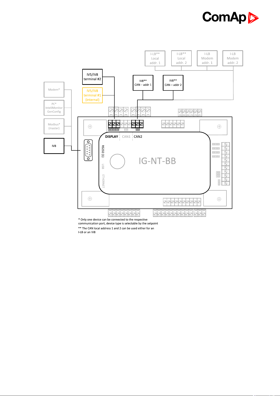
It is possible to connect up to 3 IV8 displays to RS485(1) terminal Link (see IG/IS/IM-NTC-BB - Terminals on
page 13) and up to 2 displays on CAN(2) bus.
Note: Connection InteliVision8 to IG/IS-NT controllers is described in InteliVision8 Global Guide.
Note: In case of connection IV8 to controller via CAN(2) bus the collision can occur. IV8 is in this case
connected via 123 and 124 CAN (2) physical address, that can be used for other peripheral modules (see the
table bellow). Make sure, that real CAN(2) physical address (123 and 124) are not shared by other devices such
as I-LB+ module.
Real
CAN2
Address
122 - - addr.2 - - - - -
123 addr.2 addr.2 - addr.1 addr.1 addr.2 addr.2 addr.2
124 addr.1 addr.1 - addr.2 addr.2 addr.1 addr.1 addr.1
125 modem - addr.1 - - - - -
IG-MU
I-LB
(local)
(RS232/485)
I-LB
(modem)
I-LB+
(USB)
IG-IB
(IBConfig<1,5)
IG-IB
(IBConfig>1,6)
IV-
Display
Controller setup
(Setpoints/Comms settings group)
RS485(1) conv. = DISABLED
I-RD
-CAN
IGS-NT Communication Guide
63
Page 64

5.1.3 InteliVision 5 display
Controllers
Controllers IG-NT-BB IM-NT-BB IG-NTC-BB IS-NTC-BB IM-NTC-BB
Connectionapplicable YES YES YES YES YES
Physical port RS485 (1) RS485 (1) RS485 (1) RS485 (1) RS485 (1)
More info
Controllers IG-NT IM-NT IG-NTC IS-NT-BB
Connectionapplicable YES YES YES YES
Physical port RS485 (1) RS485 (1) RS485 (1) RS485 (1)
More info IG/IM-NT-BB - Terminal (page 17)
It is possible to connect up to 3 InteliVision 5 displays to RS485(1) terminal Link (IG/IS/IM-NTC-BB -
Terminals (page 13)).
Note: Connection InteliVision 5 to IG/IS-NT controllers is described in InteliVision5 Global Guide.
IG/IM-NT-BB - Terminal
(page 17)
IG/IS/IM-NTC-BB - Terminals (page 13)
IG/IS/IM-NTC-BB - Terminals (page
13)
Controller setup
(Setpoints/Comms settings group)
RS485(1) conv. = DISABLED
5.2 Comms extension - I-LB+ Local bridge
I-LB+ is communication modules for communication with all devices connected to CAN(2) bus. I-LB+ is
successors of the IG-MU unit designed to be used with IG/IS controllers. It therefore provides additional
communication port and higher communication speed. Speed for direct/modem connection can be up to 57600
bps. I-LB+ can be connected with PC via USB, RS232 or RS485. I-LB+ is with USB port (speed ≈ 115200 bps).
IGS-NT Communication Guide
64
Page 65

IGS-NT Communication Guide
65
Page 66

5.2.1 Jumper setings
Jumper Description State
P1 CAN terminating resistor Opened – not connect
P2 RS485 terminating resistor Opened – not connect
P3 RS232 or RS485 1–2 – active RS485
P8 USB enable/disable Opened – disabled
P13 Modbus rate
P14 Modbus rate
P15 HW or SW modem control Opened – HW control
P16 ComAp or Modbus Opened – ComAp protocol
P17 ADR1 or ADR2 Opened – ADR1
P18 Direct or Modem Opened – Direct
According Addr.1/Addr.2 setings real CAN address is assigned to port
RS232/485 DIRECT MODEM USB
Addr. 1 124 125 123
Addr. 2 123 122 124
It is possible to use those combinations simultaneously:
2x direct RS232/RS485 and 2x MODEM (USB communication has to be disabled, P8 is opened)
1x USB and 1x RS232/RS485
9600, 19200, 38400, 57600 bps
(according to picture: O = Open, C = Close.
5.2.2 Jumper selection tree
ComAp/ModBus – selects between ComAp PC tools (InteliMonitor, WinScope, ...) and third party PC SW for
monitoring:
ComAp
Direct/Modem – selects between direct connection (via RS232 or RS485) and modem connection type
DIRECT
RS232/RS485 – selection of serial communication type
ADR1/ADR2 – selection between two available local communication channels; if I-LB+ is used,
the USB communication automatically occupies the other channel
MODEM
HW/SW control – selection between modems with full interface
ADR1/ADR2 – selection between two available modem communication channels; IG/IS-NT
controllers only, in ID the secondary modem channel not available
Setting RS232/RS485 jumper to RS232 position is obligatory
IGS-NT Communication Guide
66
Page 67

ModBus (not available at USB port of I-LB+, USB port always works in ComAp mode)
Direct/Modem – selects between direct connection (via RS232 or RS485) and modem connection type
DIRECT
RS232/RS485 – selection of serial communication type
ADR1/ADR2 – selection between two available local communication channels; if I-LB+ is used,
the USB communication automatically occupies the other channel
MODEM
ADR1/ADR2 – selection between two available modem communication channels; IG/IS-NT
controllers only, in ID the secondary modem channel not available
Setting HW/SW control has no influence; a modem with HW control is always expected in this
mode
ModBus Rate (9600 / 19200 / 38400 / 57600 bps) – selects the communication speed when ModBus
protocol is selected, no matter if in Direct or Modem mode
Note: For more information read IGS-NT accessory modules manual.
5.3 I-CR Module for CAN Bus Extension
If the distance between units is too high to fit into the 200 m limit (or 900 m for 8 controllers), CAN repeater
module (I-CR) can be used to extend it.
Typical case – in line extension:
Connection of I-LB, combination of different CAN bus speeds:
This connection allows PC communication to all controllers in the system (e.g. via InteliMonitor), including a
distant InteliMains unit.
IGS-NT Communication Guide
67
Page 68

5.3.1 I-CR module functions
Intercontroller CAN bus extension (one or more I-CR modules can be used).
Intercontroller CAN bus bus-tie bridging – makes groups of controllers in segments A and B“invisible” one for
another depending on bus-tie breaker state, keeping the PC communication (ILB, IG-IB) in function for all
controllers.
Peripheral CAN bus extension
5.3.2 I-CR configuration jumpers
P2 Forces 250 kbps mode (32C) on CAN A, otherwise speed autodetection is used.
P3 Forces 250 kbps mode (32C) on CAN B, otherwise speed autodetection is used.
P4 Activates Filter mode (bus-tie bridging).
P5 Forces alternate controller address 3 for bus-tie status reading (default controller address is 4).
P10 If “H” network configuration used (two I-CR units), it must be switched to RS-485 mode.
Note: For more detailed information about I-CR, see the Application sheet “Extending the CAN bus” or IGS-NT-
x.y-Installation guide.pdf.
Note: CAN bus has to be terminated at both ends. In the case of surge hazard (connection out of building in
case of storm etc.) see the “CAN and RS485 bus wiring” chapter of the IGS-NT-Installation-Guide-08-2014-
r1.pdf.
5.4 I-CR-R Module for CAN Bus Redundancy
This module is intended to provide CAN bus redundancy in applications where IG/IS-NT controllers are placed
in several switchboards that need to be interconnected by the CAN bus communication line and where there is
essential to keep the line working. As a side effect, the module also provides the CAN bus line extension.
As the CAN bus provides data exchange needed for Load Sharing and VAr Sharing and also for Power
Management features, it’s redundancy can be very important in complex systems with more engines, more
mains incomers.
Note: I-CR-R may be used as a redundancy module for a maximum of 20 controllers (counted all controllers on
the CAN2 bus).
For usage I-CR-R in an installation of more as 20 controllers please contact our technical support for another
redundancy solution.
IGS-NT Communication Guide
68
Page 69

Typical case – several controllers, each one in separate switchboard
More controllers within common switchboard
IGS-NT Communication Guide
69
Page 70

Connection of I-LB+ or other bridging modules
Note: If I-LB+ (or other bridging module) is to monitor all the site, it is recommended to place it at the position 1.
If there is preferably monitored one group (within one switchboard) and the other controllers not at all or only
seldom, option 2 is more suitable. Remote connection to let’s say controller 7 is possible in this case but data
transfer will be quite slow.
5.5 I-CR-R module properties
5.5.1 I-CR-R module functions
Intercontroller CAN bus redundancy – basic description of terminology used:
Local CAN bus – a bus going from the module to the local controller(s) = within one switchboard; name
on the sticker CAN1 CONTROLLER; in standard installation (with no redundancy) this would be the
intercontroller bus (CAN2)
Primary intercontroller CAN bus – a bus interconnecting all I-CR-R modules and providing 1 to 1
replacement of standard intercontroller CAN bus (CAN2); name on the sticker CAN EMS
Backup intercontroller RS485 bus – secondary bus interconnecting all I-CR-R modules; transmits only
intercontroller communication (Load Sharing, VAr Sharing, Power Management), not the remote
communication (I-LB, IG-IB connection to a PC monitoring tool); controller with address 1 must be
presented in the system to make backup bus working
The module preferably uses the Primary CAN bus line for data transfer. However, if the connection from any
of the controllers connected to other I-CR-R modules is broken the module automatically re-routes it to the
Backup RS485 line and continues in operation. From controllers’ point of view, no data transfer interruption
is observed.
It is possible to indicate the problem with Primary or Backup buses using “fake” SHBOUT6 message which
is normally used for signal sharing among the controllers. See jumper description further in the text.
IGS-NT Communication Guide
70
Page 71

Intercontroller CAN bus extension – each I-CR-R module provides also CAN bus extension in the same
way as I-CR module, i.e. creates segments of the bus where the length of the line is limited within the
segment only, not within the whole system.
Note: The redundancy system only makes sense if the cables of Primary and Backup buses are placed
physically into different cable routes! Placing them into the same cable route increases the risk of damage of
both cables at once.
5.5.2 I-CR-R configuration jumpers
P3 – Forces 8C (50 kbps) mode on Primary intercontroller bus (name at the original sticker CAN EMS); if not
active, 32C (250 kbps) mode is automatically used.
Note: All I-CR-R modules within the system must be switched to the same mode, otherwise the primary
intercontroller CAN bus won’t work.
P4 – Enables transmission of SHBOUT6 message to local CAN bus; the message is intended to transmit
indication and error flags from the module to the controllers to make the status of the module visible to the
customers. By sending this message, I-CR-R is “cheating” the controllers in it’s local CAN bus because it is
pretending to be one of the other controllers (from intercontroller bus) sending this message. Do not use the real
source for SHBOUT6 message if this feature is enabled.
Contents of the SHBOUT6 message
Position
(bit8=highest)
bit 8 Always 1 (reserved)
bit 7 Always 1 (reserved)
bit 6 Always 0 (reserved)
bit 5 Always 0 (reserved)
bit 4 Logical 1: Modbus Master (controller with adress 1 on the line) is detected
bit 3
bit 2 Logical 1: indicates this (local) controller is Modbus Master
bit 1
Note: Typically, configure a Warning-type protection on the lowest bit signal of this message. The signal
becomes active if part of controllers normally “visible” through the Primary or Backup bus is not visible
anymore; this means the cable was cut or shorted or otherwise damaged and doesn’t connect anymore some
part or all the controllers.
RS485 overload occurred (= more data in the queue than could be transmitted via this
line)
Difference of “visible” controllers between Primary and Backup bus occurred -> Probably
failure in one of the intercontroller lines
Description
Note: Because bit 1 activates with the difference between Primary and Backup buses it is able to indicate
failures of both Primary and Backup buses, so even if Primary bus works fine, it is able to show the problem
with Backup bus to allow the technician to repair it before it actually becomes a problem. Otherwise the problem
with the Backup bus would stay hidden until Primary bus would have failed and then the intercontroller
communication would stop working completely.
IGS-NT Communication Guide
71
Page 72

5.5.3 I-CR-R indication and diagnostic LEDs
LED State Function
PWR
RUN
CONTR
EMS
CANCONTR
(TxC, RxC)
CANEMS
(TxC, RxC)
Lights
Dark If all LEDs are dark there is no power supply to the module
Lights Firmware is OK and running
Slow
flash
Fast
flash
Lights Local CAN bus is running OK (between controller and I-CR-R)
Flashes
Lights Communication on CAN bus between I-CR-Rs is running
Flashes
Flashes Local CAN interface activity
Flashes Primary intercontroller CAN interface activity
If all other LEDs except of the PWR LED are dark the FW is located in a wrong
type of module; please make sure that I-CB/CAT GAS HW is present
Firmware corrupted (periodic Watchdog reset)
RS485 was interrupted or no master found on RS485 backup bus; (controller
with address 1 must be presented in the system to make backup bus working)
No controller detected on local CAN bus; on local bus, speed 32C is always
expected (short connection only – within the switchboard)
CAN bus between I-CR-Rs was interrupted
Automatic speed detection 32C / 8C; enters this mode if no
controller/transmission detected on Primary intercontroller bus (for 2 s)
COM
(TxD, RxD)
6 back to Controller setup
Flashes Backup intercontroller RS485 interface activity
5.6 Commands for IGS-NT
First it is necessary to enter an appropriate user and his password first to enable commands, if these are
protected by level 1-7.
IGS-NT Communication Guide
72
Page 73

Command
(*)
Meaning Argument(*) Return Value(*)
000001FF OK
Start the engine – in one
step (page 106)
01FE0000
2
000002FE OK
Argument has
not been
written
Engine stop 02FD0000
1
Horn reset 04FB0000 000004FC OK
Fault reset 08F70000 000008F8 OK
ECU Fault reset 10EF0000 000010F0 OK
other 1
Close/open generator circuit
breaker (IGS-NT)
Clutch ON/OFF (ID)
Close generator circuit breaker 11EF0000
Open generator circuit breaker 11F00000
11EE0000
2
000011EF OK
2
000011F0 OK
2
000011F1 OK
2
Argument has
not been
written
Wrong
argument
Argument has
not been
written
Argument has
not been
written
Argument has
not been
written
2
Close/open mains circuit
breaker
Close mains circuit breaker 12EE0000
Open mains circuit breaker 12EF0000
12ED0000
other 1
000012EE OK
Argument has
2
000012EF OK
2
000012F0 OK
2
not been
written
Argument has
not been
written
Argument has
not been
written
Wrong
argument
IGS-NT Communication Guide
73
Page 74

Command
(*)
5 Reset from Init state (#1) 44440000
7 Statistics reset 007C0000
8 Set kWh counter New value N/A
C Set kVAhr counter New value N/A
D Set counter of engine starts New value N/A
E Set runhours counter New value N/A
Meaning Argument(*) Return Value(*)
00004445 OK
1
0000007D OK
1
Not possible
to perform
Not possible
to perform
19
1A
1F,20,21,22
23,24,25,26 Set ExtValue1-4 (#2)
Note:
(*) in HEX
Set counter of unsuccessful
engine starts
Remote Switch 1-8 – Set
(Remote Control 1-8) (page
103)
(RemoteControl1-8)
Reset binary output
RemoteSwitch1-8
(RemoteControl1-8)
Set pulse counters (IS-NT
only)
New value N/A
00200000 N/A
00100000 N/A
XXXXYYYY (XXXX)
Upper part of a new value;
YYYY – Lower part of a new
value)
0000YYYY (YYYY -
newvalue)
Upper
value +1
1, 2
3 OK
1, 2
OK
Not possible
to perform
Not possible
to perform
#8
If the controller setpoints are not valid after it is switched on, the controller goes to a blocked state. In this state
it is necessary to modify the setpoints from the controller keypad and switch off and on the controller or from the
external terminal and unblock the controller by Reset from Init state command. Another condition necessary to
unblock the application function of the controller is valid configuration.
#2
Check if the setpoints ExtValueXLoLim and ExtValueXHiLim allow set the requested value to ExtValue.
Note: Writing command and argument in one step is possible only with direct connection to controller. If the
communication is via brigde (IB-NT or I-LB+), it is necessary to write the command and argument in two steps,
please see Examples of Modbus Communication on page 93.
IGS-NT Communication Guide
74
Page 75

5.7 Commands for IM-NT
First it is necessary to enter an appropriate user and his password to enable commands, if these are protected
by level 1-7.
Command Meaning Argument(*) Return Value(*)
000001FF OK
Start command 01FE0000
1
Stop command 02FD0000
Horn reset 04FB0000 000004FC OK
Fault reset 08F70000 000008F8 OK
other 1 Wrong argument
Close/open MGCB 11EE0000
2
000002FE OK
2
000011EF OK
2
Argument has not
been written
Argument has not
been written
Argument has not
been written
Close MGCB 11EF0000
Open MGCB 11F00000
2
Close/open MCB / BTB 12ED0000
Close MCB / BTB 12EE0000
Open MCB / BTB 12EF0000
other 1 Wrong argument
5 Reset from Init state (#1) 44440000
000011F0 OK
2
000011F1 OK
2
000012EE OK
2
000012EF OK
2
000012F0 OK
2
00004445 OK
1
Argument has not
been written
Argument has not
been written
Argument has not
been written
Argument has not
been written
Argument has not
been written
Not possible to
perform
8 Set kWh counter New value N/A
C Set kVAhr counter New value N/A
Set binary output RemoteSwitch1-8
001A
IGS-NT Communication Guide
(RemoteControl1-8)
Reset binary output RemoteSwitch1-
00200000x(**) N/A
00100000x(**) N/A
75
Page 76

Command Meaning Argument(*) Return Value(*)
8 (RemoteControl1-8)
23,24,25,26 Set ExtValue1-4 (#2)
Note:
(*) in HEX
Note:
(**) x: switch1 =0, switch2 =1,... switch8 =7
#9
If the controller setpoints are not valid after it is switched on, the controller goes to a blocked state. In this state
it is necessary to modify the setpoints from the controller keypad and switch off and on the controller or from the
external terminal and unblock the controller by Reset from Init state command. Another condition necessary to
unblock the application function of the controller is valid configuration.
#2
Check if the setpoints ExtValueXLoLim and ExtValueXHiLim allow set the requested value to ExtValue.
6 back to Controller setup
0000YYY (YYYY -
new value)
3 OK
1, 2
Not possible to
perform
IGS-NT Communication Guide
76
Page 77

6 Connection
6.1 Recommended CAN/RS485 connection 77
6 back to Table of contents
6.1 Recommended CAN/RS485 connection
6.1.1 CAN bus connection
The bus has to be terminated by 120 Ohm resistors at both ends.
The bus has to be terminated by 120 Ohm resistors at both ends. External units can be connected on the CAN
bus line in any order, but keeping line arrangement (no tails, no star) is necessary.
Standard maximum bus length is 200m for 32C CAN BUS MODE and 900m for 8C CAN BUS MODE (setpoint
in comms setings group).
Shielded cable has to be used, shielding has to be connected to PE on one side (controller side). Recommended
data cables: BELDEN (www.belden.com)
For shorter distances (up to 50 m): 3105A Paired - EIA Industrial RS-485 PLTC/CM (1x2 conductors)
For longer distances: 3106A Paired - EIA Industrial RS-485 PLTC/CM (1x2+1 conductors)
In case of surge hazard: 3106A Paired - EIA Industrial RS-485 PLTC/CM (1x2+1 conductors)
IGS-NT Communication Guide
77
Page 78

6.1.2 CAN/fiber optic converter
Image 6.1 Extends CAN bus length by 2000m
Recommended converters
ADF Web HD67181FS or HD67181FSX (www.ADFweb.com)
www.adfweb.com/home/products/optics_fibres_can_bus_repeaters.asp
It is simple converter without redundant power supply. It has no alarm contact. Wide Power Supply voltage:
8-19VAC or 8-35VDC. DIN mounting. Multimode version only. Number of converters in cascade is limited.
Tested 4 optical links (8 converters) in cascade with no problem with communication. However “star”
topology is better to use.
Recommended settings
Use converter Baud Rate Setting to 250k if setpoint Comms setting: CAN bus mode is set to 32C in controllers:
Use converter Baud Rate Setting to 50k if setpoint Comms setting: CAN bus mode is set to 8C in controllers:
IMPORTANT: This device can extend total CAN bus length by 2000m (HD67181FSX only) using
optical link, but total length of metalic CAN bus must not exceed these values:
200 m if setpoint Comms setting: CAN bus mode is set to 32C in controllers
900 m if setpoint Comms setting: CAN bus mode is set to 8C in controllers
IGS-NT Communication Guide
78
Page 79

eks
www.eks-engel.de/produkte/fiber-optics/interface/dl-can-dl-can-r/
DL-CAN/1x13 – Point to point
DL-CAN/2x13 – Bus topology without redundancy
DL-CANR/2x13 – Redundant link topology
Industrial converters with dual (redundant) power supply 12-30VDC. Alarm contacts available. DIN
mounting. Available multimode and single mode version.
IMPORTANT: This device can extend total CAN bus length by 100km between 2 converters (single
mode version only) using optical link, but total length of metalic CAN bus must not exceed these
values:
200 m if setpoint Comms setting: CAN bus mode is set to 32C in controllers
900 m if setpoint Comms setting: CAN bus mode is set to 8C in controllers
6.1.3 CAN-Ethernet gateway
CAN-Ethernet gateway allows you to merge up to four CAN bus branches into one global CAN bus using
Ethernet connection. For detailed information about this option see:
www.comap-control.com/login?q=%2fsupport%2fknowledge-base%2fas10-ethernet-based-can-extension-r1-
(1)-pdf&nodeid=3134&class=ComAp.File
IGS-NT Communication Guide
79
Page 80

Note: For CAN bus extension is possible to use I-CR module. It allows extension of CAN to more segments
with next 200m adition length. for more information see I-CR Module for CAN Bus Extension on page 67.
6.1.4 RS485 connection
External units can be connected on the RS485 line in any order, but keeping line arrangement (no tails, no star)
is necessary.
Standard maximum line length is 1000m.
Shielded cable has to be used, shielding has to be connected to PE on one side (controller side).
RS485 bus line has to be terminated by 120 ohm resistors on the both ends. Always check the number and
placement of terminating resistors in the RS485 bus line, only correct wiring ensures reliable operation!
Resistors must be placed at either end of the line (see picture), and correct number of resistors must be used!
Correct number can be checked using ohmmeter - when power supply for ALL devices on the RS485 bus line is
switched off, the resistance measured between A and B wire should be 60 Ohms. For longer distances is
recommended to connect RS485 COM terminals between all controllers and cable shielding to the ground in one
point. External units can be connected on the RS485 bus line in any order, but line arrangement (no tails no star)
is necessary.
Availability of embedded galavanic separation of RS485 port in ComAp products
All InteliGen controllers - port RS485(1) NO
All InteliSys controllers - port RS485(1) NO
All InteliGen controllers - port RS485(2) YES
All InteliSys controllers - port RS485(2) YES
IG-Display, IS-Display - port RS485 YES
InteliVision 8 - port RS485, CAN YES
InteliVision 5 - port RS485 NO
InteliVision 5 RD - port RS485 YES
InteliVision 5 CAN - port CAN YES
InteliVision 12Touch - port RS485, CAN YES
IGS-NT Communication Guide
80
Page 81

6.1.5 Termination Resistors
Because each differential pair of wires is a transmission line, you must properly terminate the line to prevent
reflections. A common method of terminating a two-wire multidrop RS-485 network is to install terminating
resistors at each end of the multidrop network. If you daisy-chained multiple instruments together, you need a
terminating resistor at only the first and last instruments. The terminating resistor should match the
characteristic impedance of the transmission line (typically 100–120 Ohms).
6.1.6 Bias Resistors
The transmission line into the RS-485 port enters an indeterminate state when it is not being transmitted to. This
indeterminate state can cause the receivers to receive invalid data bits from the noise picked up on the cable.
To prevent these data bits, you should force the transmission line into a known state. By installing two 620 Ohm
bias resistors at one node on the transmission line, you can create a voltage divider that forces the voltage
between the differential pair to be less than 200 milli-Volts, the threshold for the receiver. You should install
these resistors on only one node. The figure below shows a transmission line using bias resistors. Bias
resistors are placed directly on the PCB of controller. Use jumpers PULL UP/PULL DOWN to connect the bias
resistors.
6 back to Connection
IGS-NT Communication Guide
81
Page 82

7 Communication
7.1 Communication cables 82
7.2 SMS Message command 85
7.3 Modbus Communication 90
7.4 Examples of Modbus Communication 93
7.5 Reserved communication objects 111
7.6 Replacing InternetBridge-NT 113
6 back to Table of contents
7.1 Communication cables
Recommended communication cables for ComAp controllers
Interface Cable Connector Max. Length
Serial cross-wired cable
RS232
RS485 Shield twisted pair
Ethernet STP or UTP cable RJ45 100 m 10/100Mbps
USB
CAN Shield twisted pair
standard Null-modem
cable
1
Standard USB A-B
cable
2
DB 9 10 m 57.6kBd
DB 9 10 m
NONE 1000 m 57.6kBd
USBA-USBB 5 m 115200 Bd
NONE 200m/900m 250 kBd
7.1.1 RS 485 cable
For longer distances: 3106A Paired - EIA Industrial RS-485 PLTC/CM (1x2+1 conductors) Recommended
data cables: BELDEN (www.belden.com)
For shorter distances (up to 50 m): 3105A Paired - EIA Industrial RS-485 PLTC/CM (1x2 conductors)
Max. Comm.
Rate
IGS-NT Communication Guide
82
Page 83

7.1.2 CAN bus cable
Galvanically separated
Maximal CAN bus length 200m Speed 250kBd
Nominal impedance 120Ω
Cable type twisted pair (shielded)
Following dynamic cable parameters are important especially for maximal 200 meters CAN bus length and 32
iS-COM units connected:
Nominal Velocity of Propagation min. 75% (max. 4,4 ns/m)
Recommended data cables: BELDEN (www.belden.com)
For shorter distances (up to 50 m): 3105A Paired - EIA Industrial RS-485 PLTC/CM (1x2 conductors)
For longer distances: 3106A Paired - EIA Industrial RS-485 PLTC/CM (1x2+1 conductors)
7.1.3 RS232 cable
It is recommended to use standard Null-modem cable for local connection between controller and PC, although
the three wires (TxD, RxD, GND) RS 232 connection is enough for direct controller to PC communication:
7.1.4 Cables for direct and modem connections
PC to RS232 on controller/I-LB
DB9 Female to DB9 Female
2 3
3 2
5 5
IGS-NT Communication Guide
83
Page 84

Modem to RS232 on controller/I-LB
Comms settings: MODEM (HW) or I-LB jumper HW control
DB9 Male to DB9 Female
1 1
2 2
3 3
4 4
5 5
6 6
7 7
8 8
9 9
Comms settings: MODEM (SW) or I-LB jumper SW control
DB9 Male to DB9 Female
2 2
3 3
5 5
7.1.5 USB cable
Use standard USB A-B cable (distance up to 5 meters).
IMPORTANT: Use shielded USB cable only! (ComAp order code: USB-LINK CABLE 1.8m).
Note: To use USB connection it is necessary to install drivers on your PC.
The drivers can be downloaded from the website www.ftdichip.com/Drivers/VCP.htm.
Download the driver for your operating system and follow the enclosed instructions.
After successful installation of the driver and connection of the controller or I-LB+ to the PC the new Virtual
Communications Port appears in ComAp PC tools and it is possible to open connection via USB.
IGS-NT Communication Guide
84
Page 85

7.1.6 Ethernet cable
It is recommended to use standard UTP or STP cable with connectors RJ 45. Maximal length of cable is 100 m.
For direct connection between Controller and PC is necessary to use cross-wired cable (only in case that your
PC does not have automatic recognizing of direct and cross-wired cable).
Image 7.1 Cross-wired UTP 10/100Mbit cable
7.2 SMS Message command
7.2.1 Controller address
InteliGen/InteliSys Access code is 15 characters length string. Access code is separated
from controller address by column.
Syntax:
Example:
7.2.2 Access code
Controller address is unique controller identification number located in setpoint group Basic setting : Contr addr
[1 to 32].
#5:X
X … controller access code up to 15 characters length
#5:accesscode
Message is addressed to controller with address 5 and its access code is set to value
‘accesscode’.
Syntax:
Example:
IGS-NT Communication Guide
#XX
XX … controller address [1 to 32]
#5
Message is addressed to controller with address 5.
85
Page 86

7.2.3 Read value or setpoint
Command for reading of selected value or setpoint. Return value is in appropriate numerical or string format.
r XXXX (or rXXXX)
Syntax:
Example:
Note: Access code can’t contain space character. Access code can be changed in InteliMonitor only.
r … command
XXXX… value or setpoint code
#5:accesscode r 8252
Reading of setpoint 8252 (8252 = Gear teeth)
7.2.4 Adjust setpoint
Command for adjusting of selected setpoint. Answer message contains only confirmation of successful
adjusting or appropriate error.
w XXXX YYYY (or wXXXX YYYY)
Syntax:
Example:
w … command
XXXX… setpoint code
YYYY… value of setpoint in appropriate format
#5:accesscode w 8252 144
Adjusting of setpoint 8252 to value 144 (8252 = Gear teeth).
ok … adjusting setpoint was correct
w_err … adjusting setpoint was not successful
Returncode:
er_pass … adjusting setpoint required that valid password was entered
er_old … command for adjusting was read out from SMS during GSM modem initialization –
in this case command will not be served.
7.2.5 Enter password
Password setting command. Password has to be set before adjusting of protected setpoint or calling protected
gen-set control command. Setting password command is not necessary before every adjusting. Password is a
number in range 0 to 65535 and is valid for all rest of SMS.
p PPPP (or pPPPP)
Syntax:
Example:
Return code:
p … command
PPPP… password
#5:accesscode p 1234, w 8252 144
Setting password before adjusting protected setpoint.
ok … setting password was successful
er_pass … setting password is not valid
IGS-NT Communication Guide
86
Page 87

7.2.6 Gen-set control
SMS command for invoking gen-set control command as Start, Stop, Fault reset etc.
c Y (or cY)
c … command
Y … type of operation
Y Type of operation Y Type of operation
Syntax:
Example:
Returncode:
1 Start 7 MCB ON
2 Stop 8 MCB OFF
3 Horn Reset 9 GCB ON/OFF
4 Fault Reset 10 MCB ON/OFF
5 GCB ON 11 Next Mode
6 GCB OFF 12 Previous Mode
#5:accesscode p 1234, c1
This SMS command invokes gen-set Start. Password setting is needed in case of
password protection was configured for gen-set commands.
ok … gen-set command was accepted
er_pass … valid password was not set before executing the command
c? … unknown gen-set command
c_er … gen-set command execution is not allowed in actual state (e.g. attempt to start the
gen-set in OFF mode).
er_old … command was read out from SMS during GSM modem initialization – in this case
command will not be served.
7.2.7 Read Alarm list
Read actual Alarm list.
Syntax:
Example:
Returncode:
Note:
1. Answer message contains at most eight items of Alarm list.
2. Alarm list is not separated to more messages.
a
a … command
#5:accesscode a
Request of actual Alarm list.
AL=(items of alarm list) … comma separated items of Alarm list. Exclamation mark in front
of Alarm list item indicates inverse record (still active alarm).
IGS-NT Communication Guide
87
Page 88

7.2.8 Time delay
Insert time delay before serving next part of SMS command.
d T
Syntax:
Example:
Returncode:
Note: Any other SMS messages are not served during time delay!
d … command
T … time delay in sec (in range 1 to 600)
#5:accesscode d 10
Request 10 sec delay before serving next SMS command.
d_ok … time delay was successful performed
d_over … requested time delay is out of range (1 to 600 sec)
7.2.9 Remote switches (IG/IS-NT only)
Set or reset RemoteControl1-8 output.
s 1/0
Syntax:
Example:
Returncode: p_OK,s_OK
s … command
1/0 … set/reset
#5:accesscode p0, s1 1
Enters password p0 and sets RemoteControl1 output.
7.2.10 ExtValues (IG/IS-NT only)
Enters value to ExtValue.
e xxx
Syntax:
Example:
Returncode:
Note: Return code is not separated to more message.
e … command
xxx … value
#5
Message is addressed to controller with address 5.
?=(p <user:>passwd,r comm_obj,w com_obj val,c cmd_num,d sec,a,sx y,ex y,?)…... .....
list of supported SMS commands
IGS-NT Communication Guide
88
Page 89

7.2.11 Answer message
Answer message start with # character followed by Gen-set name. Colon separates this header form return
codes of SMS commands. Answer message is generated during serving of received message and is sent in
case that 160 characters or end of received message are achieved. Answer message is sent to the originator
phone number. Tree dots at the end of message indicate separation and next following message.
Example:
#5:accesscode r8252,w8252 100,r8252
answer message
#Gen-setname: 144,ok,100
7.2.12 Examples of SMS commands
Here is following several examples of SMS messages addresses to controller IG/IS-NT with address 5, named
‘Gen-set name’. Access code in this controller is set to ‘accesscode’ and password is ‘1234’. In examples are
used setpoints and values 8276 – Nomin.power, 10123 – RPM, 8315 – Controller Mode, 8235 – binary inputs,
8296 – Gen > f.
Example 1 – reading value
SMS #5:accesscode r8276 read value 8276
Answer #Gen-set name:100
Example 2 – adjusting setpoint
read value 8276,
write 110,
read value 8276
Password was accepted, read value of 8276 is 100,
writing to 8276 was ok, new value of 8276 is 110
Password was not accepted,
read value of 8276 is 100
writing to 8276 was not successful
read value of 8276 is still 100
SMS
Answer
#5:accesscode p 1234,
r8276,w8276 110,r8276
#Gen-set name:ok,100,ok,110
If wrong password sent: #Gen-set
name:p_er,100, w_pass, 100
Example 3 – Gen-set control and delay time
read value 8276,
SMS
#5:accesscode
r8276,c1,d30,r10123
invoke gen-set command START,
delay 30 sec,
read value 10123
Answer #Gen-set name:110,ok,d_ok,1499
IGS-NT Communication Guide
read value of 8276 is 110,
Gen-set command START was accepted,
confirm delay command,
read value of 10123 is 1499
89
Page 90

Example 4 – adjusting special setpoint
read value 8315,
SMS #5:accesscode r8315,w8315 0,r8315
Answer #Gen-set name:MAN,ok,OFF
Note: Setpoints Stringlist type (e.g. Controller Mode) is read as string and adjusted as index of string item in
string list. e.g. Controller Mode:
Read value [as string] Write value [as index]
OFF 0
MAN 1
SEM 2
AUT 3
TEST 4
write 0 (index of stringlist type),
read value 8315
read value of 8315 as string,
writing was ok,
read new value of 8315 as string
Example 5 – reading and writing other type
SMS #5:accesscode r8235,w8296 110.2
Answer #Gen-set name:OIIIOOIIO,ok
Note:
1. Writing of binary setpoint is not supported.
2. Writing of setpoint with decimal point is automatically converted to appropriate number of decimal places.
read value 8235,
write 110.2 with decimal point
read value of 8235 (binary value),
writing was ok
Example 6 – reading actual Alarm list
SMS #5:accesscode a read actual Alarmlist
Answer
#Gen-set name:AL=(!Wrn PrimWater temp, !Wrn SecWater
temp, Batt volt)
Actual Alarm list contains three
items.
7.3 Modbus Communication
Note: It is possible to define your own Modbus register numbers for any value or setpoint in the BaseBox
controllers with standard FW v3.0 (IG-NT-BB, IS-NT-BB and IM-NT-BB firmware) and higher. For more
information about this function please refer to the chapter User Modbus (page 144).
Note: In the first time, you have to correctly configure the controller connection (see Important setpointsin
the controller on page 129).
IGS-NT Communication Guide
90
Page 91

7.3.1 Data reading
The function Read Multiple Registers (page 133) has to be used for data reading. The terminal sends a query
and from the controller receives either the normal response containing the requested data or the exceptional
response indicating a read error.
It is possible to use function 3 for reading (see Read Multiple Registers on page 133).
It is not possible to read from the middle. The register number must correspond with the beginning of the
data object. The only exception are the objects of „multipacket values“(registers 46367 – 46491) and „data
part of the history record“(registers 46543 – 46667).
All read registers must be implemented. If an unimplemented register appears among the read registers, the
controller returns an error message.
Even unnamed values can be included among read registers. The read value must be treated as
meaningless.
The length of a block is 127 registers.
7.3.2 Data writing
All data can be written by the function Write Multiple Registers (page 138). Data up to 2 bytes can be written
by the function Write Single Registers (page 137), too. The terminal sends a query containing a written data
and the controller either confirms it (normal response) or refuses it (exceptional response).
For writing it is possible to use function 6 (Write Single Registers (page 137)) or function 16 (Write
Multiple Registers (page 138)).
Using function 16 it is possible to write maximum 16 registers at once.
Data cannot be written from the middle. Register number must correspond with the beginning of the data
object. Written data must be complete to perform writing of all requested data objects.
Writing to EEPROM is executed using a queue. The queue is common for writing from all terminals. The
request for next writing is accepted in case that there is empty space in the queue. Otherwise the controller
returns an error message and the terminal must repeat the request.
All written registers must be implemented. If an unimplemented register appears among the read registers,
the controller returns an error message.
It is possible to include also unnamed registers in the written sequence. The controller confirms this writing
but writing of unnamed registers is not performed.
IGS-NT Communication Guide
91
Page 92

Request
Controller address (1 - 32), you can set or check your controller’s address in the controller setpoints.
Setpoints -> Comms settings -> Contr.address
Modbus function code, you can use the 3, 6, 16 Modbus function code
Function 3 (Read Multiple Registers)
Function 6 (Write Single Register)
Command 10
Function 16 (Write Multiple Registers)
Register address (40001 - 47168), it means Modbus address of controller communication object (setpoint,
value, et al.). You can create list of Modbus registers, if you can’t find the register address in this list.
Number of registers (1 - 127). It means, how many registers you want read.
CRC (no range)
After sent your request, you receive the response. The response has also five parts:
Controller address (1 - 32), the same as the address in the request
Modbus function code (3,6,16, …), mostly the same as in the request
Length of data (1 - 127), here is specified the length of the received data
Data (0 - FF), data are in the HEX form, length is defined above
Check field calculation (page 143) (no range)
Note: The setpoints in IG-NT are placed in EEPROM which has maximum 500 000 of rewrites. Please
consider how fast the setpoints are overwritten. (1 sec writing period, 6 days ~ 500 000 rewrites). IS-NTC-BB
using memory with maximum of 500 000 000 rewrites.
IGS-NT Communication Guide
92
Page 93

7.4 Examples of Modbus Communication
In this chapter are some examples, how does communicate controller via Modbus.
7.4.1 Battery voltage – reading (read multiple registers) 94
7.4.2 Values (Oil press, Water temp, Fuel level) – reading 96
7.4.3 Binary input - reading 97
7.4.4 Password decode - reading 97
7.4.5 Gen-set name - reading 98
7.4.6 Engine state - reading 99
7.4.7 Gear teeth – writing 100
7.4.8 Nominal Power – writing 100
7.4.9 Mode – writing 101
7.4.10 Reset/Confirm Alarm 102
7.4.11 Remote Switch 1-8 – Set (Remote Control 1-8) 103
7.4.12 External Value1 – writing 104
7.4.13 User & Password – in two steps 105
7.4.14 User & Password – in one step 106
7.4.15 Start the engine – in one step 106
7.4.16 Start the engine – in two steps 107
7.4.17 History – reading 107
7.4.18 AlarmList reading 109
7.4.19 Change the communication language (only String type data) 110
IGS-NT Communication Guide
93
Page 94

7.4.1 Battery voltage – reading (read multiple registers)
Request: 01 03 00 0C 00 01 44 09
01
03 = Modbus function code (Read Multiple Registers)
00 0C
00 01
= Controller address
See your controller settings
= Register address: Register number (Ubat => 40013)
40013 - 40001 = 12 DEC => 000C HEX
See your Cfg Image or list of Reserved
communication objects (page 111)
= Number of registers
40013, it is one register = 01 DEC => 0001 HEX
You have to calculate number of register which
you want read
= CRC
09 44
Response: 01 03 02 00 DC B9 DD
01
03
02
CRC has to be written LSB then MSB ! See how
to calculate Check field calculation (page
143).
= Controller address
See your controller settings
= Modbus function code (Read Multiple Registers
(page 133))
= Length of read data in Bytes (in HEX)
02 HEX => 2 DEC
Define the length of data
IGS-NT Communication Guide
94
Page 95

00 DC
= Value of battery voltage
DC HEX => 220 DEC => Batt. voltage is
represented with 1 decimal => 22,0 VDC
convert the data from hex to dec. Use the
multiplication factor (In this case 0.1)!
DD B9
= Check field calculation (page 143)
Check with your CRC, because of data validity
IGS-NT Communication Guide
95
Page 96

7.4.2 Values (Oil press, Water temp, Fuel level) – reading
Request: 01 03 00 0F 00 03 35 C8
01 = Controller address
03
00 0F
00 03
C8 35 = CRC (write LSB MSB !)
Response: 01 03 06 00 27 00 2E 00 2B 35 64
01 = Controller address
03
= Modbus function code (Read Multiple Registers
(page 133))
= Register address: Register number (40016) – 40001 =
15 DEC => 0F HEX
= Number of registers (40016 – Oil press, 40017 –
Water temp, 40018 – Fuel level)
= 3 DEC = > 03 HEX
= Modbus function code (Read Multiple Registers
(page 133))
06 = Length of read data in Bytes (in HEX)
00 27
00 2E
00 2B
64 35 = Check field calculation (page 143)
= 27 HEX => 39 DEC => 3,9 Bar (Oil pressure is
represented with 1 decimal in Bars)
= 2E HEX => 46 DEC => 46°C (Water temperature is
represented with 0 decimals in °C)
= 2B HEX => 43 DEC => 43% (Fuel level is
represented with 0 decimals in %)
IGS-NT Communication Guide
96
Page 97

7.4.3 Binary input - reading
Request: 01 03 00 02 00 01 25 CA
01 = Controller address
03
00 02
00 01 = Number of registers (40003) = 01 DEC => 01 HEX
CA 25
Response: 01 03 02 00 0A 38 43
01 = Controller address
03
02 = Length of read data in Bytes (in HEX)
00 0A
43 38 = Check field calculation (page 143)
= Modbus function code (Read Multiple Registers
(page 133))
= Register address: Register number (40003) – 40001
= 02 DEC => 02 HEX
= Check field calculation (page 143) (write LSB MSB
!)
= Modbus function code (Read Multiple Registers
(page 133))
= Object data value (Binary input =
00000000000001010 i.e. BI2 and BI4 are set)*
7.4.4 Password decode - reading
Request: 01 03 00 A0 00 02 C4 29
01 = Controller address
03 = Modbus function code (Read Multiple Registers (page 133))
00 A0 = Register address: Register number (40161) – 40001 = 160 DEC => A0 HEX
00 02 = Number of registers (40161 and 40162) = 02 DEC => 02 HEX
29 C4 = Check field calculation (page 143) (write LSB MSB !)
Response: 01 03 04 68 73 90 00 7B 88
01 = Controller address
03 = Modbus function code (Read Multiple Registers (page 133))
04 = Length of read data in Bytes (in HEX)
68 73 90 00 = 68739000 HEX => 1752403968 DEC = > password decode is 1752403968
88 7B = Check field calculation (page 143)
IGS-NT Communication Guide
97
Page 98

7.4.5 Gen-set name - reading
Request: 01 03 0B B8 00 08 C6 0D
01 = Controller address
03 = Modbus function code (Read Multiple Registers (page 133))
0B B8
00 08 = Number of registers (43001 - 43008) = 08 DEC => 08 HEX
0D C6 = Check field calculation (page 143) (write LSB MSB !)
Response: 01 03 10 49 47 53 2D 4E 54 00 00 00 00 00 00 00 00 00 00 D7 6A
01 = Controller address
03 = Modbus function code (Read Multiple Registers (page 133))
10 = Length of read data in Bytes (in HEX)
49 47 = Object data value (IG)
53 2D = Object data value (S-)
4E 54 = Object data value (NT)
00 00 = Object data value (_ _)
00 00 = Object data value (_ _)
00 00 = Object data value (_ _)
00 00 = Object data value (_ _)
00 00 = Object data value (_ _) =.> gen-set name is IGS -NT
6A D7 = Check field calculation (page 143)
= Register address: Register number (43001) – 40001 = 3000 DEC =>
BB8 HEX
IGS-NT Communication Guide
98
Page 99

7.4.6 Engine state - reading
Request: 01 03 00 A2 00 01 25 E8
01 = Controller address
03
00 A2
00 01 = Number of registers (40163)
E8 25
Response: 01 03 02 00 02 39 85
01 = Controller address
03
02 = Length of read data in Bytes (in HEX)
00 02
85 39 = Check field calculation (page 143)
= Modbus function code (Read Multiple Registers
(page 133))
= Register address: Register number (40163) – 40001
= 162 DEC => A2 HEX
= Check field calculation (page 143) (write LSB MSB
!)
= Modbus function code (Read Multiple Registers
(page 133))
= Object data value – see the List#1 in the Cfg Image
=> (NotReady)
IGS-NT Communication Guide
99
Page 100

7.4.7 Gear teeth – writing
Request: 01 06 0B D0 00 7D 4A 36
01 = Controller address
06 = Modbus function code (Write Single Registers (page 137))
0B D0 = Register address: Register number (43025) – 40001 = 3024 DEC => BD0 HEX
00 7D = Gear teeth > 125 DEC => 7D HEX
36 4A = Check field calculation (page 143) (write LSB MSB !)
Response: 01 06 0B D0 00 7D 4A 36
01 = Controller address
06 = Modbus function code (Write Single Registers (page 137))
0B D0 = Register addres
00 7D = Set the setpoint gear teeth to > 7D HEC => 125 DEC = 125
36 A4 = Check field calculation (page 143)
7.4.8 Nominal Power – writing
Request: 01 06 0B C0 01 F4 8B C5
01 = Controller address
06 = Modbus function code (Write Single Registers (page 137))
0B C0 = Register address: Register number (43009) – 40001 = 3008 DEC => BC0 HEX
01 F4 = Nominal power > 500 DEC => 1F4 HEC
C5 8B = Check field calculation (page 143) (write LSB MSB !)
Response: 01 06 0B C0 01 F4 8B C5
01 = Controller address
06 = Modbus function code (Write Single Registers (page 137))
0B C0 = Register addres
01 F4 = Set the setpoint nominal power to > 1F4 HEC => 500 DEC = 500
C5 8B = Check field calculation (page 143)
IGS-NT Communication Guide
100
 Loading...