

Page 1
Copyright © 2014 ComAp a.s.
Written by Petr Novák
Prague, Czech Republic
ComAp a.s.
Kundratka 2359/17, 180 00 Praha 8, Czech Republic
Tel: +420 246 012 111, Fax: +420 2 66316647
E-mail: info@comap.cz, www.comap.cz
Reference Guide
InteliLiteNT
InteliLite NT AMF
Modular Gen-set Controller
Compact Controller for Stand-by Operating Gen-sets
(IL-NT AMF20/25 unit)
SW version 2.2, March 2016
Page 2

Table of Contents
Table of Contents .................................................................................................................................... 2
General Guidelines .................................................................................................................................. 5
What describes this manual? .............................................................................................................. 5
!! Warnings !! ....................................................................................................................................... 5
Symbols ............................................................................................................................................... 5
Text ..................................................................................................................................................... 6
Dangerous voltage .............................................................................................................................. 6
Adjust set points .................................................................................................................................. 6
General Description ................................................................................................................................. 7
Description of the controller system (with all options) ......................................................................... 7
What is in the package? ...................................................................................................................... 7
IL-NT RS232 Communication plug-in card ......................................................................................... 7
IL-NT RS232-485 Communication plug-in card ................................................................................ 11
IL-NT S-USB Service USB communication plug-in card .................................................................. 12
IB-Lite Ethernet communication plug-in card .................................................................................... 13
IL-NT-GPRS GSM and GPRS plug-in modem ................................................................................. 14
IL-NT AOUT8 Gauge driver module.................................................................................................. 15
IL-NT BIO8 Hybrid binary input/output module ................................................................................. 17
IC-NT CT-BIO7.................................................................................................................................. 18
IL-NT RD Remote display software................................................................................................... 18
Remote annunciator IGL - RA15 ....................................................................................................... 18
IG IOM/PTM module ......................................................................................................................... 19
IG-IB Internet bridge .......................................................................................................................... 20
InternetBridge-NT .............................................................................................................................. 21
IL-NT Terminals ..................................................................................................................................... 22
IL-NT terminals and front face ........................................................................................................... 22
Installation.............................................................................................................................................. 23
Mounting ............................................................................................................................................ 23
Dimensions ........................................................................................................................................ 24
Recommended Wiring ........................................................................................................................... 25
AMF – Wiring Diagram ...................................................................................................................... 25
Stand-by Applications ............................................................................................................................ 26
Contactors (set point MCB Logic = “CLOSE-OFF”) .......................................................................... 26
ATS with two stable positions (set point MCB Logic = “CLOSE-ON”) .............................................. 26
ATS with three stable positions (set point MCB Logic = “CLOSE-OFF”) .......................................... 27
Dual Mutual Standby (Dual AMF) application ................................................................................... 27
Getting Started ...................................................................................................................................... 30
How to install ..................................................................................................................................... 30
Current measurement ....................................................................................................................... 34
Earth Fault measurement (module) .................................................................................................. 36
Voltage measurement and generator connection types ................................................................... 37
Analog inputs..................................................................................................................................... 40
Binary inputs and outputs .................................................................................................................. 46
Recommended CAN/RS485 connection ........................................................................................... 47
Extension modules (CAN bus) connection ....................................................................................... 49
Inputs and Outputs ................................................................................................................................ 50
Binary inputs IL-NT - default ............................................................................................................. 50
Binary inputs – list ............................................................................................................................. 50
Binary outputs IL-NT - default .......................................................................................................... 54
Binary outputs - list ............................................................................................................................ 55
Analog inputs..................................................................................................................................... 65
Analog outputs .................................................................................................................................. 65
Setpoints ................................................................................................................................................ 66
Password ........................................................................................................................................... 66
Basic Settings.................................................................................................................................... 66
InteliLiteNT– AMF20/25, SW version 2.2, ©ComAp – September 2014 2
IL-NT-AMF-2.2-Reference Guide.pdf
Page 3

Comms Settings ................................................................................................................................ 70
Engine Params .................................................................................................................................. 73
Engine Protect ................................................................................................................................... 77
Gener Protect .................................................................................................................................... 79
AMF Settings ..................................................................................................................................... 81
*Extension I/O ................................................................................................................................... 85
Date/Time .......................................................................................................................................... 85
Sensors Spec .................................................................................................................................... 87
SMS/E-Mail ....................................................................................................................................... 87
Alternate Cfg ..................................................................................................................................... 89
*EarthFaultProt .................................................................................................................................. 90
*ECU-controlled engine support ............................................................................................................ 92
Identifying configured ECU ............................................................................................................... 93
Values read from ECU ...................................................................................................................... 93
Diagnostic messages read from ECU ............................................................................................... 94
Analog inputs..................................................................................................................................... 94
Connection description ...................................................................................................................... 95
Sensor Specification .............................................................................................................................. 98
Background of the sensor calibration ................................................................................................ 98
Default sensor curves ....................................................................................................................... 98
Function Description .............................................................................................................................. 99
OFF Mode ......................................................................................................................................... 99
MAN Mode ........................................................................................................................................ 99
AUT Mode ....................................................................................................................................... 101
TEST mode ..................................................................................................................................... 102
Circuit breakers timing .................................................................................................................... 102
Alarm Management ............................................................................................................................. 105
Sensor Fail (FLS) ............................................................................................................................ 105
Warning (WRN) ............................................................................................................................... 105
Breaker open and cooling (BOC) .................................................................................................... 105
Shut down (SD) ............................................................................................................................... 106
Mains failure (MF) ........................................................................................................................... 106
Voltage phase sequence detection ................................................................................................. 106
Gen-set Operation States .................................................................................................................... 108
List of possible events ..................................................................................................................... 110
History file ........................................................................................................................................ 112
Init Screens .......................................................................................................................................... 115
Customer Logo screen .................................................................................................................... 115
Firmware Init screen ........................................................................................................................ 115
Language screen ............................................................................................................................ 115
User Interface screen ...................................................................................................................... 115
Remote Control and Data Logging ...................................................................................................... 116
PC software - LiteEdit ..................................................................................................................... 116
Direct cable connection ................................................................................................................... 116
Modem connection .......................................................................................................................... 117
Internet connection .......................................................................................................................... 118
IB-Lite .............................................................................................................................................. 119
IL-NT-GPRS .................................................................................................................................... 120
InternetBridge-NT ............................................................................................................................ 125
IG-IB ................................................................................................................................................ 125
AirGate ............................................................................................................................................ 125
Locate .............................................................................................................................................. 125
SNMP protocol ................................................................................................................................ 125
Modbus protocol .............................................................................................................................. 127
Communication object list ............................................................................................................... 127
IL-NT-RD Remote display software ................................................................................................ 132
Maintenance ........................................................................................................................................ 137
Backup battery replacement ........................................................................................................... 137
Technical Data ..................................................................................................................................... 139
Inputs/Outputs overview .................................................................................................................. 139
InteliLiteNT– AMF20/25, SW version 2.2, ©ComAp – September 2014 3
IL-NT-AMF-2.2-Reference Guide.pdf
Page 4

Generator protections ..................................................................................................................... 139
Language support ........................................................................................................................... 139
Power supply ................................................................................................................................... 140
Operating conditions ....................................................................................................................... 140
#
Low Temperature modification ...................................................................................................... 140
Dimensions and weight ................................................................................................................... 141
Mains and generator ....................................................................................................................... 141
Binary inputs and outputs ................................................................................................................ 141
Analog inputs................................................................................................................................... 142
Speed pick-up input ........................................................................................................................ 142
D+ Function ..................................................................................................................................... 142
*CAN bus interface .......................................................................................................................... 142
IL-NT RS232 interface (optional card) ............................................................................................ 143
IL-NT RS232-485 interface (optional card) ..................................................................................... 143
IL-NT S-USB interface (optional card) ............................................................................................ 143
IL-NT AOUT8 interface (optional card) ........................................................................................... 143
IC-NT CT-BIO7 interface (optional card) ........................................................................................ 144
IL-NT BIO8 interface (optional card) ............................................................................................... 144
IGS-PTM ......................................................................................................................................... 145
IGL-RA15 ........................................................................................................................................ 145
IG-IB ................................................................................................................................................ 145
InteliLiteNT– AMF20/25, SW version 2.2, ©ComAp – September 2014 4
IL-NT-AMF-2.2-Reference Guide.pdf
Page 5

General Guidelines
Grounding
point symbol
AC voltage
symbol
DC voltage
symbol
What describes this manual?
IMPORTANT SAFETY INSTRUCTIONS
SAVE THESE INSTRUCTION - This manual contains important instructions for IL-NT
controllers family that shall be followed during installation and maintenance of the InteliLite NT genset
controllers.
It is intended for use by gen-set control panel builders and for everybody who is concerned with
installation, operation and maintenance of the gen-set.
This manual describes „AMF 20/25“ software which is designed for single set stand-by applications.
What is the purpose of the manual?
This manual provides general information how to install and operate InteliLite-NT AMF20/25 controller.
This manual is dedicated for
Operators of gen-sets
Gen-set control panel builders
For everybody who is concerned with installation, operation and maintenance of the gen-set
!! Warnings !!
Remote control
InteliLite controller can be remotely controlled. In case of the work on the gen-set check, that nobody
can remotely start the engine.
To be sure:
Disconnect remote control via RS232 line
Disconnect input REM START/STOP
or
Disconnect output STARTER and outputs GCB CLOSE/OPEN and MCB CLOSE/OPEN
Because of large variety of InteliLiteNT parameters settings, it is not possible to describe any
combination. Some of InteliLite functions are subject of changes depend on SW version.
The data in this manual only describes the product and are not warranty of performance or
characteristic.
InteliLite controller SW and HW versions compatibility
Be aware that IL-NT SW version 1.2.1 and older is not possible to use with IL-NT HW version 1.3 and
newer!!! Software IL-NT 1.3 is compatible with IL-NT hardware version 1.3 and older.
Symbols
Symbols used in this manual:
InteliLiteNT– AMF20/25, SW version 2.2, ©ComAp – September 2014 5
IL-NT-AMF-2.2-Reference Guide.pdf
Page 6

Text
Every time you want disconnect following InteliLiteNT controller terminals:
Mains voltage measuring and / or
Binary output for MCB control and / or
MCB Feedback
Switch InteliLite to MAN or OFF Mode or disconnect the Binary outputs Starter and
Fuel to avoid unexpected automatic start of gen-set and GCB closing.
!!! CAUTION !!!
Dangerous voltage
In no case touch the terminals for voltage and current measurement!
Always connect grounding terminals!
In any case do not disconnect InteliLiteNT CT terminals!
Adjust set points
All parameters are preadjusted to their typical values. But the set points in the “Basic settings” settings
group !!must!! be adjusted before the first startup of the gen-set.
!!! WRONG ADJUSTMENT OF BASIC PARAMETERS
CAN DESTROY THE GEN-SET !!!
The following instructions are for qualified personnel only. To avoid personal injury do
not perform any action not specified in this User guide !!!
PAGE (Capital letters in the frame) buttons on the front panel
Break Return (Italic) set points
Generator protections (Bold) Set point group
REMOTE START/STOP (Capital letters) binary inputs and outputs
*Something (Symbol * before text) valid only for IL-NT AMF 25
Note:
ComAp believes that all information provided herein is correct and reliable and reserves the right to
update at any time. ComAp does not assume any responsibility for its use unless otherwise expressly
undertaken.
Note:
SW and HW must be compatible (e.g. IL-NT-AMF25 firmware and IL-NT AMF25 HW) otherwise the
function will be disabled. If wrong software is downloaded, message HARDWARE INCOMPATIBLE
appears on controller screen. In this case download correct software and use Boot jumper
programming – close Boot jumper and follow instructions in LiteEdit or follow video guide “Boot
Jumper Programming“ at http://www.comap.cz/support/training/training-videos/.
WARNING – VERY IMPORTANT !!!
InteliLiteNT– AMF20/25, SW version 2.2, ©ComAp – September 2014 6
IL-NT-AMF-2.2-Reference Guide.pdf
Page 7

General Description
Accessories
Description
Optional / Obligatory
IL-NT AMF
InteliLiteNT central unit
Obligatory
IL-NT-RS232
RS232 communication card
Optional for AMF20/25
IL-NT-RS232-485
RS232 and RS485 communication card
Optional for AMF20/25
IL-NT-S-USB
Service USB communication card
Optional for AMF20/25
IB-Lite
Ethernet communication card
Optional for AMF20/25
IL-NT-GPRS
GSM/GPRS modem card
Optional for AMF20/25
IL-NT-AOUT8
Gauge driver plug-in card
Optional for AMF20/25
IL-NT-BIO8
Configurable I/O plug-in card
Optional for AMF20/25
IC-NT-CT-BIO7
Configurable I/O plug-in card with earth
fault current measurement
Optional for AMF20/25
**IL-NT RD
Remote display software
Optional for AMF20/25
IGL-RA15
Remote annunciator
Optional for AMF25
IG-IOM/PTM
I/O extension module
Optional for AMF25
IG-IB
Internet communication bridge
Optional for AMF20/25
InternetBridge-NT
External communication module
Optional for AMF20/25
AT-LINK-CONV
Service programming RS232 interface
Optional for AMF20/25
AT-LINK-CABLE
Serial RS232 communication cable 1,8m
Optional for AMF20/25
Description of the controller system (with all options)
InteliLiteNT AMF20/25 is a comprehensive AMF-controller for single generating sets operating in standby mode. IL-NT AMF25 features extended support of electronic engines and extension modules.
InteliLiteNT controllers are equipped with a powerful graphic display showing icons, symbols and bargraphs for intuitive operation, which sets, together with high functionality, new standards in Gen-set
controls.
InteliLiteNT automatically starts the Gen-set, closes the Gen-set C.B. when all conditions are met, then
stops the engine on external signal or by pressing push buttons.
InteliLiteNT provides gas engine support without ventilation.
The key feature of InteliLiteNT is its easy-to-use operation and installation. Predefined configurations
for typical applications are available as well as user-defined configurations for special applications.
What is in the package?
**Remote display for IL-NT controllers uses standard IL-NT controller with Remote
display software
Hint:
For detailed information about extension modules used with IL-NT controllers, please see the IL-NTAccessory Modules manual.
IL-NT RS232 Communication plug-in card
IL-NT RS232 is optional plug-in card to enable InteliLiteNT for RS 232 communication. This is required
for computer or Modbus connecting. Card inserts into expansion slot back on the controller.
InteliLiteNT– AMF20/25, SW version 2.2, ©ComAp – September 2014 7
IL-NT-AMF-2.2-Reference Guide.pdf
Page 8
To insert the module, you must open the cover first (use screwdriver to open) and then insert the
module into slot. Once you have insert it, the module will snap under plastic teeth. It is supposed to be
installed permanently. Should you need to remove it, the safest way is to remove whole back cover
and then remove module manually.
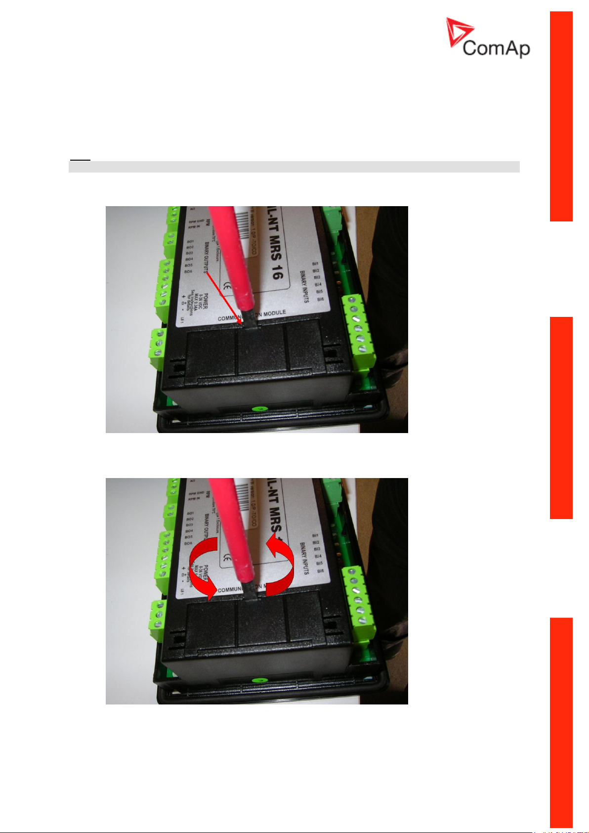
How to install RS 232 communication module:
Hint:
The following procedure is analogic also for other communication modules.
1. Insert a screwdriver into the slot of the cover.
2. Move the screwdriver to set apart the small cover. Be careful!
3. Remove the small cover.
InteliLiteNT– AMF20/25, SW version 2.2, ©ComAp – September 2014 8
IL-NT-AMF-2.2-Reference Guide.pdf
Page 9
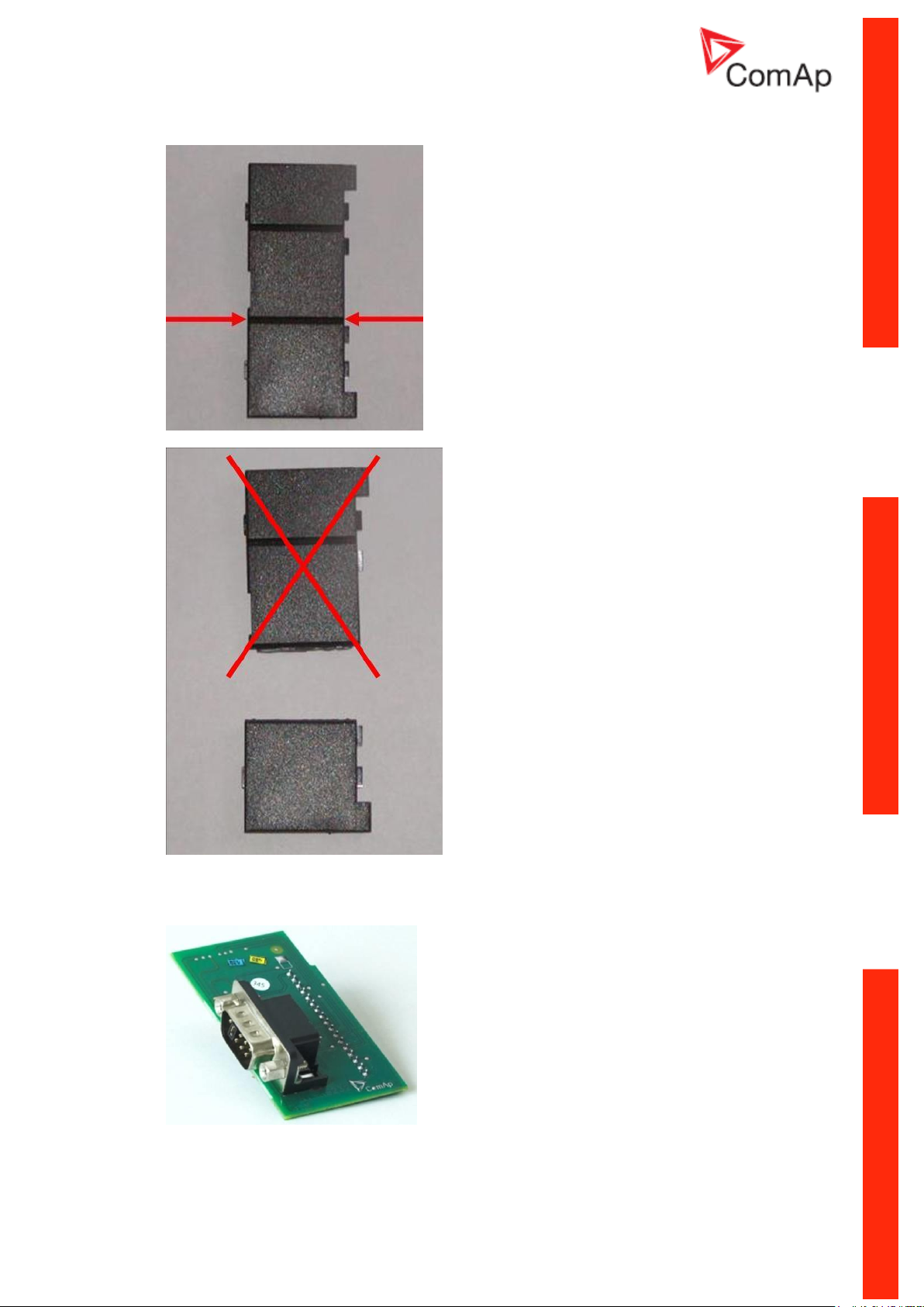
4. Break apart the small cover into two pieces. Do not throw away the smaller part!
5. Take RS 232 communication module.
InteliLiteNT– AMF20/25, SW version 2.2, ©ComAp – September 2014 9
IL-NT-AMF-2.2-Reference Guide.pdf
Page 10

6. Plug RS 232 communication module into the slot of the controller.
7. Put back the small cover.
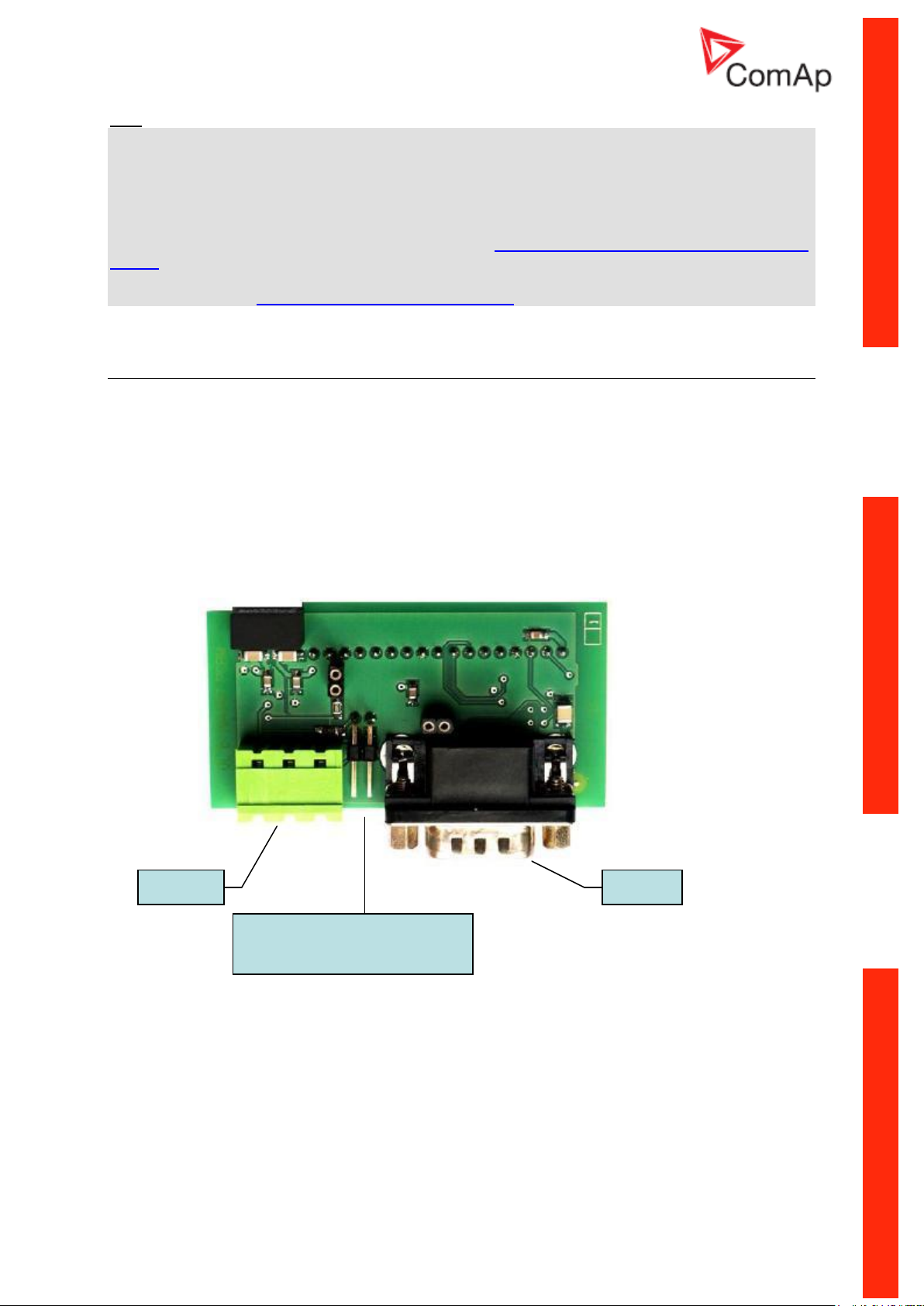
Hint:
When you insert RS 232 communication module, the boot jumper is hidden. For that reason we
recommend to use RS 232 communication module with the boot jumper placed on it. See pictures
below:
RS 232 communication module with the boot jumper.
InteliLiteNT– AMF20/25, SW version 2.2, ©ComAp – September 2014 10
IL-NT-AMF-2.2-Reference Guide.pdf
Page 11
Hint:
RS485
RS232
Boot jumper and
RS485 Terminator jumper
Boot jumper programming – In case of interrupted programming or other software failure is possible to
use the boot jumper programing to restore controller to working order. Connect controller to PC, run
LiteEdit and wait until connection bar at bottom turns red. Than run programming process via menu
Controller -> Programming and cloning – Programming. Select correct firmware and confirm dialog.
Than follow instructions in LiteEdit.
Or follow video guide “Boot Jumper Programming“ at http://www.comap.cz/support/training/training-
videos/.
- Please see chapter IL-NT RS232 interface (optional card) for technical details.
IL-NT RS232-485 Communication plug-in card
IL-NT RS232-485 is optional plug-in card to enable InteliLiteNT the RS232 and RS485 communication.
This is required for computer or Modbus connection. Card inserts into expansion slot back on the
controller. The IL-NT RS232-485 is a dual port module with RS232 and RS485 interfaces at
independent COM channels. The RS232 is connected to COM1 and RS485 to COM2.
To insert the module, please follow the instructions for IL-NT RS232 module, procedure is analogous.
You must open the cover first (use screwdriver to open) and then insert the module into slot. Once you
have insert it, the module will snap under plastic teeth. It is supposed to be installed permanently.
Should you need to remove it, the safest way is to remove whole back cover and then remove module
manually.
InteliLiteNT– AMF20/25, SW version 2.2, ©ComAp – September 2014 11
IL-NT-AMF-2.2-Reference Guide.pdf
Page 12
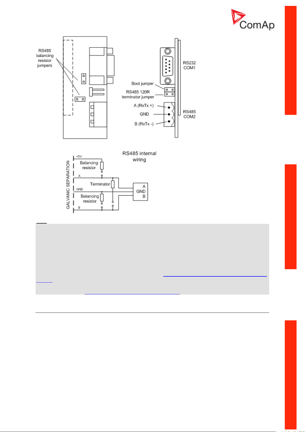
Hint:
- Balancing resistors shall be both closed at only one device in whole RS485 network.
- Boot jumper programming – In case of interrupted programming or other software failure is possible
to use the boot jumper programing to restore controller to working order. Connect controller to PC, run
LiteEdit and wait until connection bar at bottom turns red. Than run programming process via menu
Controller -> Programming and cloning – Programming. Select correct firmware and confirm dialog.
Than follow instructions in LiteEdit.
Or follow video guide “Boot Jumper Programming“ at http://www.comap.cz/support/training/training-
videos/.
- Please see chapter IL-NT RS232-485 interface (optional card) for technical details.
IL-NT S-USB Service USB communication plug-in card
IL-NT S-USB is optional plug-in card to enable InteliLiteNT communication via USB port. This is
required for computer or Modbus connecting. Card inserts into expansion slot back on the controller.
To insert the module, please follow the instructions for IL-NT RS232 module, procedure is analogous.
You must open the cover first (use screwdriver to open) and then insert the module into slot. Once you
have inserted it, part of the module will remain over plastic box. It is supposed to be used as a service
tool. When you need to remove it, grab module in cutouts and pull it up manually.
InteliLiteNT– AMF20/25, SW version 2.2, ©ComAp – September 2014 12
IL-NT-AMF-2.2-Reference Guide.pdf
Page 13
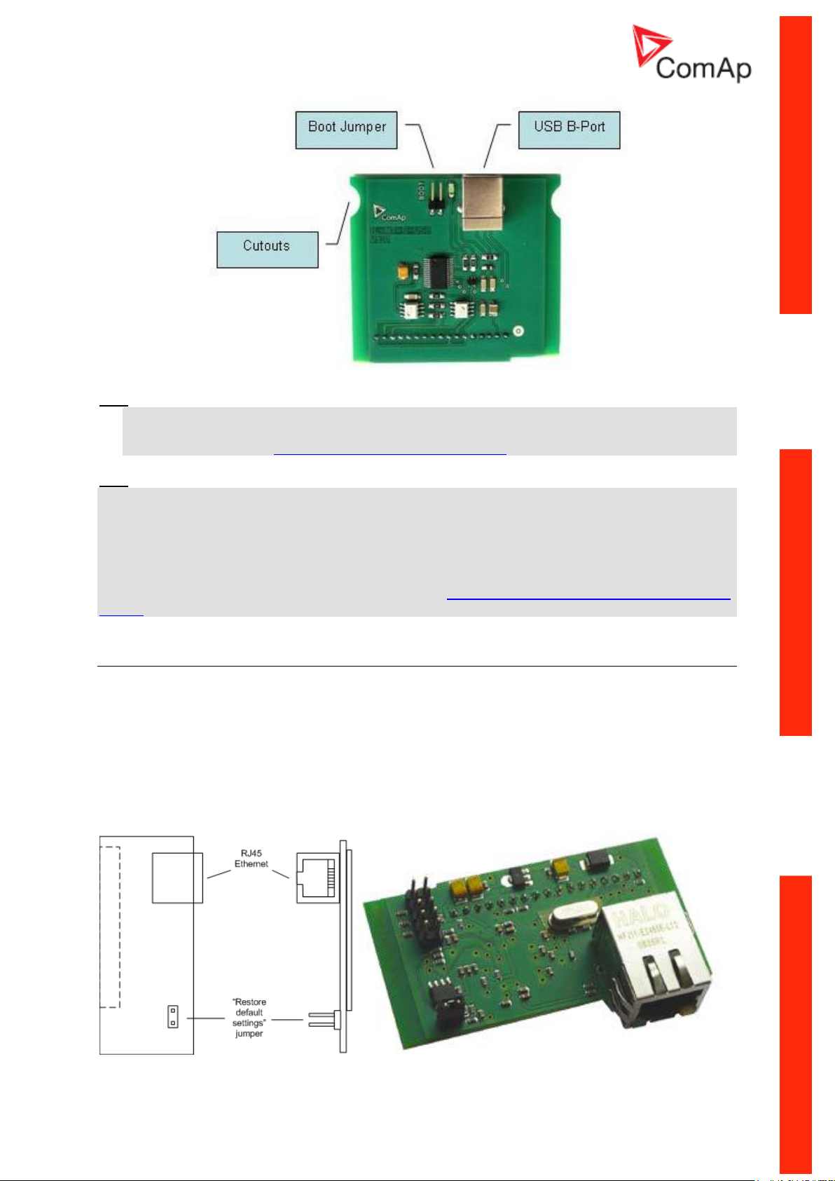
Hint:
- Use the shielded USB A-B cable with this module! Recommended is ComAp cable – Order
code: “USB-LINK CABLE 1.8M”.
- Please see chapter IL-NT S-USB interface (optional card) for technical details.
Hint:
Boot jumper programming – In case of interrupted programming or other software failure is possible to
use the boot jumper programing to restore controller to working order. Connect controller to PC, run
LiteEdit and wait until connection bar at bottom turns red. Than run programming process via menu
Controller -> Programming and cloning – Programming. Select correct firmware and confirm dialog.
Than follow instructions in LiteEdit.
Or follow video guide “Boot Jumper Programming“ at http://www.comap.cz/support/training/training-
videos/.
IB-Lite Ethernet communication plug-in card
IB-Lite is a plug-in card with Ethernet 10/100 Mbit interface in RJ45 connector. The card is internally
connected to both COM1 and COM2 serial channels and provides an interface for connecting a PC
with LiteEdit or InteliMonitor through ethernet/internet network, for sending active e-mails and for
integration of the controller into a building management (Modbus TCP protocol).
This card also enables to monitor and control the genset over web browser from any location with
internet access using appropriate security measures.
Card inserts into expansion slot back on the controller. To insert the module, please follow the
instructions for IL-NT RS232 module, procedure is analogous.
InteliLiteNT– AMF20/25, SW version 2.2, ©ComAp – September 2014 13
IL-NT-AMF-2.2-Reference Guide.pdf
Page 14
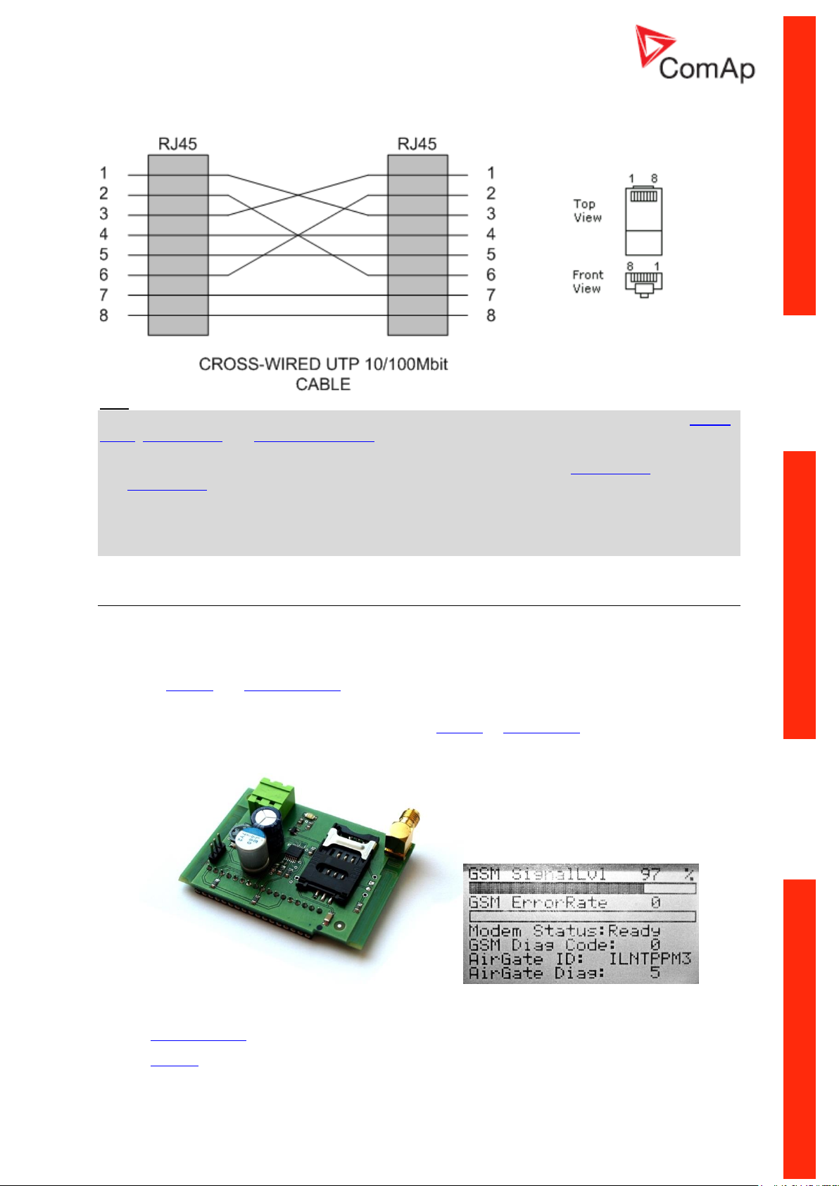
Use Ethernet UTP cable with RJ45 connector for connection of the module into your ethernet network.
The module can be also connected directly to a PC using cross-wired UTP cable.
Hint:
The controller is able to detect IB-Lite and performs automatic configuration. Related setpoints COM1
Mode, COM2 Mode and ModbusComSpeed remain unchanged. This applies to firmware versions 2.2
or higher.
Modbus TCP protocol using IB-Lite communication module requires setting COM1 Mode = DIRECT
and COM2 Mode = MODBUS.
Connection to LiteEdit via IP address is not possible if AirGate function is enabled. In this case use
AirGate connection. If you require connection using IP address, kindly disable setpoint “Airgate
[ENABLE, DISABLE]”.
For details see newest version of IB-Lite Reference Guide.
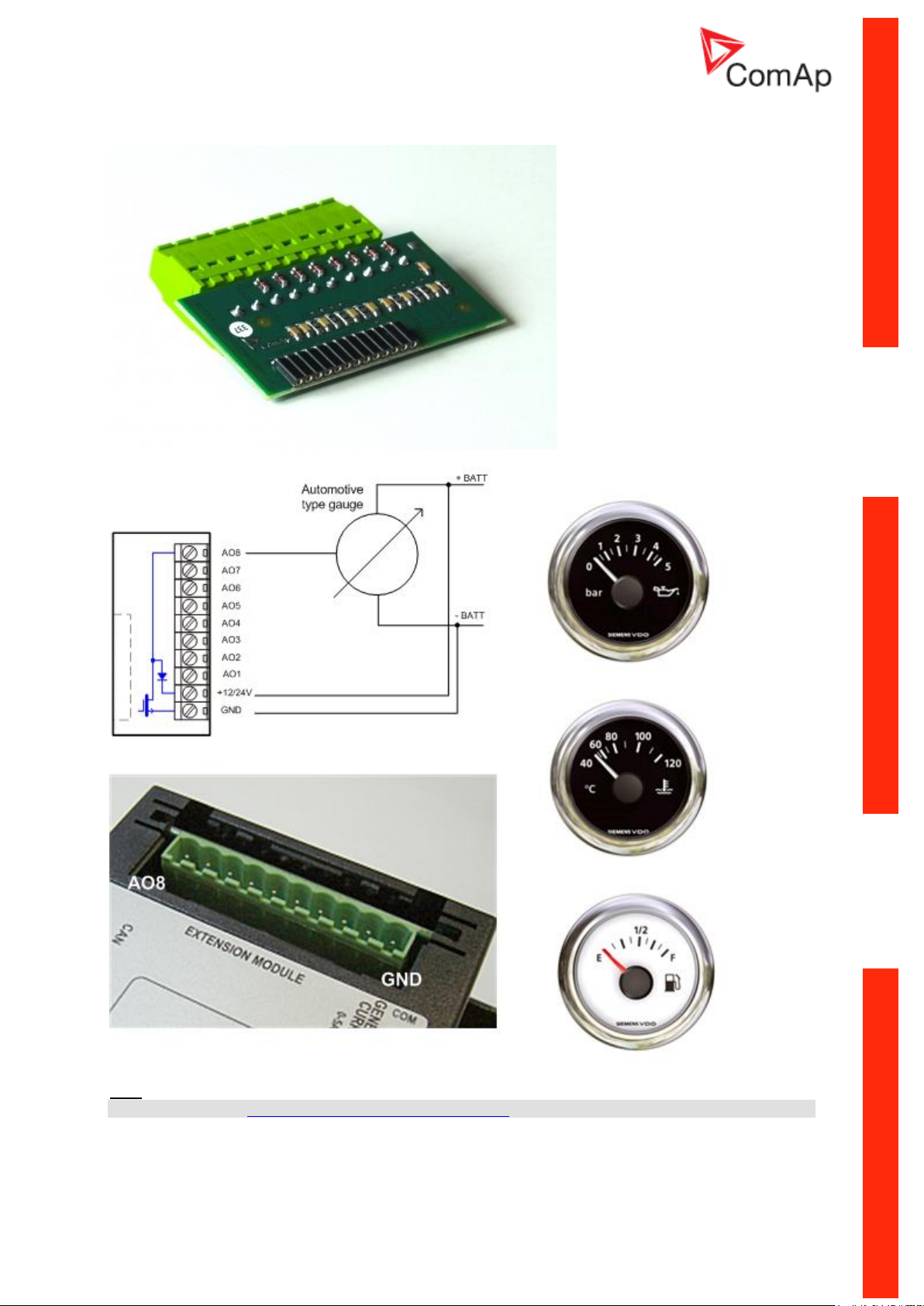
IL-NT-GPRS GSM and GPRS plug-in modem
This plug-in module is a GSM/GPRS modem which can work in two modes of operation based on the
settings in the setpoint COM1 Mode.
Settings DIRECT = the module works in a GPRS network and enables connection via AirGate
to LiteEdit and WebSupervisor as well as sending SMS alarms.
Settings MODEM = the module works as a standard GSM modem enabling a CSD (Circuit
Switch Data) connection to the controller with LiteEdit or InteliMonitor and sending SMS
alarms.
IL-NT GPRS MODULE AND GSM/GPRS SCREEN ON IC-NT DISPLAY
The communication module IL-NT GPRS works with:
WebSupervisor – internet-based remote monitoring solution
AirGate – powerful connection technology to make internet access as simple as possible
InteliLiteNT– AMF20/25, SW version 2.2, ©ComAp – September 2014 14
IL-NT-AMF-2.2-Reference Guide.pdf
Page 15

Locate – localization technology
Hint:
GPRS and CSD services must be provided by your GSM/GPRS operator for successful operation.
Hint:
The GPRS and CSD connection should not be used for the firmware update process. Use instead a
wired connection like RS232, USB, RS485 or Ethernet via IB-Lite!
Hint:
It is necessary to power the controller and individually the IL-NT GPRS module as well.
Hint:
The controller can physically reset IL-NT-GPRS module in case of “frozen” communication. This
function is supported with IL-NT-GPRS (HW version 1.2) only!
Hint:
Quick guide how to start using this module is in chapter Remote Communication - Short guide how to
start using IL-NT-GPRS module or on ComAp webpage http://www.comap.cz/products/detail/IL-NTGPRS
Hint:
IL-NT GPRS module doesn´t support a sending of e-mails.
Hint:
Any manipulation of the IL-NT GPRS module should be done only without voltage.
IL-NT AOUT8 Gauge driver module
IL-NT AOUT8 is optional plug-in card. Through this card controller can drive up to 8 VDO style
industrial/automotive gauges. Noncompensated gauges like 0-10V or 0-20mA are not supported.
Gauge type and value are configured in LiteEdit software. Any analog value from controller may be
shown in that way.
To insert the module, you must open the cover first (use screwdriver to open) and then insert the
module into slot. Once you have insert it, the module will snap under plastic teeth. It is supposed to be
installed permanently. Should you need to remove it, the safest way is to remove whole back cover
and then remove module manually.
Installing IL-NT AOUT8 module is similar to installing RS 232 module. The difference is that module
fits to “extension module” slot and after installing IL-NT AOUT8 you do not put back the small cover.
PC Installation Suite consist a set of prepared converting curves for basic usage of PWM outputs with
automotive gauges.
InteliLiteNT– AMF20/25, SW version 2.2, ©ComAp – September 2014 15
IL-NT-AMF-2.2-Reference Guide.pdf
Page 16
IL-NT AOUT8 module:
Typical wiring
Hint:
Please see chapter IL-NT AOUT8 interface (optional card) for technical details.
InteliLiteNT– AMF20/25, SW version 2.2, ©ComAp – September 2014 16
IL-NT-AMF-2.2-Reference Guide.pdf
Page 17
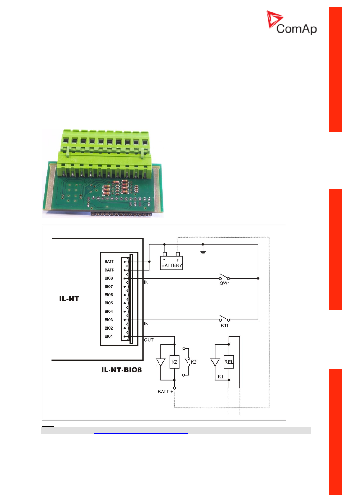
IL-NT BIO8 Hybrid binary input/output module
IL-NT BIO8 is optional plug-in card. Through this card controller can accommodate up to 8 binary
inputs or outputs. In LiteEdit configuration is possible to easily choose if particular I/O will be binary
input or output.
To insert the module, you must open the cover first (use screwdriver to open) and then insert the
module into slot. Once you have insert it, the module will snap under plastic teeth. It is supposed to be
installed permanently. Should you need to remove it, the safest way is to remove whole back cover
and then remove module manually.
Installing IL-NT BIO8 module is similar to installing RS 232 module. The difference is that module fits
to “extension module” slot and after installing IL-NT BIO8 you do not put back the small cover.
Hint:
Please see chapter IL-NT BIO8 interface (optional card) for technical details.
InteliLiteNT– AMF20/25, SW version 2.2, ©ComAp – September 2014 17
IL-NT-AMF-2.2-Reference Guide.pdf
Page 18
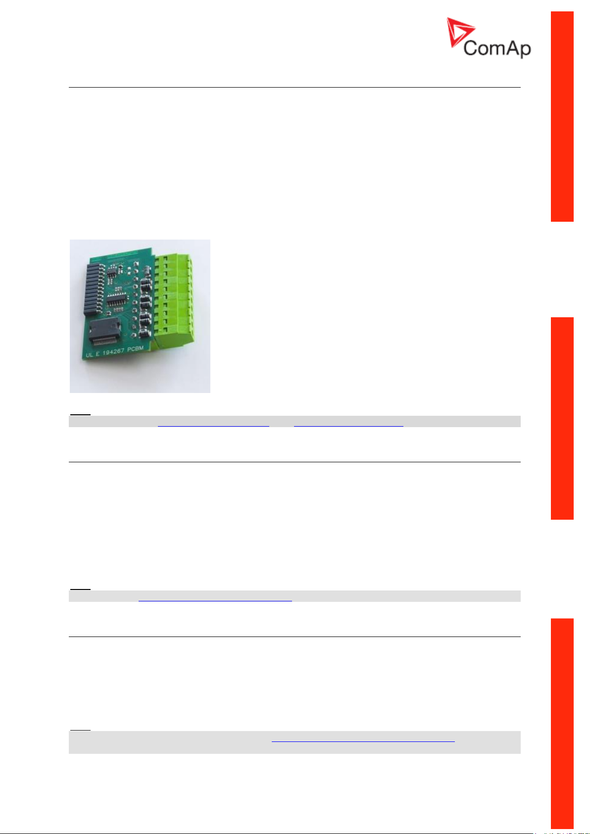
IC-NT CT-BIO7
Hybrid current input and binary input/output module
IC-NT CT-BIO7 is optional plug-in card. Through this card controller can accommodate one AC
current (CT) measuring input and up to 7 binary inputs or outputs. In LiteEdit PC configuration tool
(version 4.4 and higher) it is possible to easily choose if particular I/O will be binary input or output.
To insert the module, you must open the cover first (use screwdriver to open) and then insert the
module into slot. Once you have inserted it, the module will snap under plastic teeth. It is supposed to
be installed permanently. Should you need to remove it, the safest way is to remove whole back cover
and then remove module manually. Installing IC-NT CT-BIO7 module is similar to installing RS 232
module. The difference is that module fits to “extension module” slot and after installing IC-NT CTBIO7 you do not put back the small cover.
Hint:
See more details in Earth Fault measurement or in IC-NT CT-BIO7 interface chapter.
IL-NT RD Remote display software
IL-NT RD is remote display software for a controller. Remote display provides the same control and
monitoring functions as controller itself. Remote display for IL-NT controllers uses standard IL-NT
controller with Remote display software. No further programing of the display is required – unit is selfconfigurable from the main controller. It is connected with the controller via IL-NT-RS232
communication modules using RS232 line. Longer distances (up to 1200m) are possible using IL-NTRS232-485 communication module or when RS232/RS485 converters are used.
The IL-NT RD hardware type should fit to the master IL-NT.
Hint:
Please see the IL-NT-RD Remote display software chapter for more details.
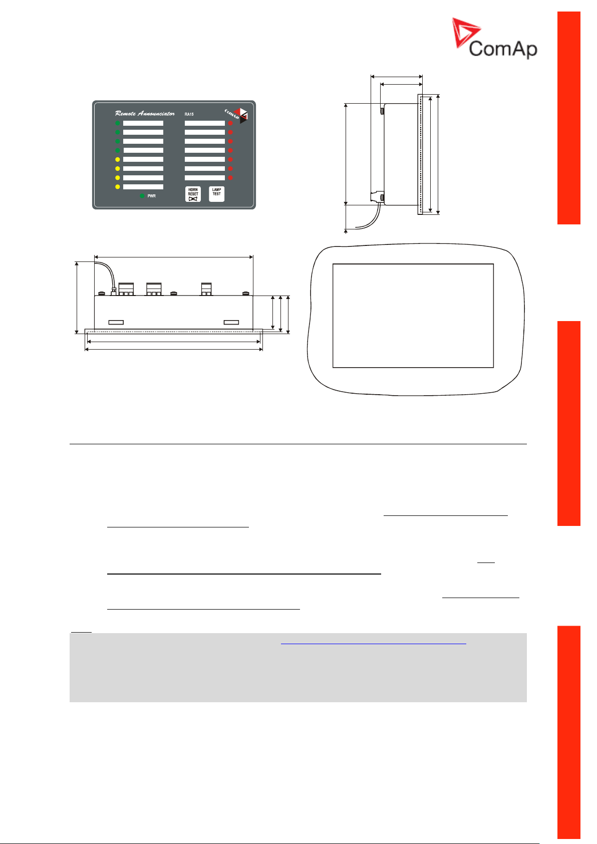
Remote annunciator IGL - RA15
The remote annunciator IGL-RA15 can be connected to the IL-NT unit via CAN bus. Any of the binary
outputs can be configured (using LiteEdit software) to each LED diode on the RA15. The module can
be also enabled or disabled using LiteEdit software.
If IGL-RA15 remote annunciator is not communicating with a controller via CAN bus, it activates a
warning.
Hint:
For connection details please refer to chapter Extension modules (CAN bus) connection.
Please see the documentation of RA15 for the technical and function description.
InteliLiteNT– AMF20/25, SW version 2.2, ©ComAp – September 2014 18
IL-NT-AMF-2.2-Reference Guide.pdf
Page 19
165 (6,5”)
38 (1,5”)
40 (1,6”)
~ 75 (3,0”)
~ 35 (1,4”)
180 (7,1”)
185 (7,3”)
106 (4,2”)
44 (1,7”)
54 (2,1”)
~ 25 (1,0”)
120 (4,7”)
125 (4,9”)
Cutout
for Remote Announciator
167 x 108 mm
(6,6 x 4,3 )”
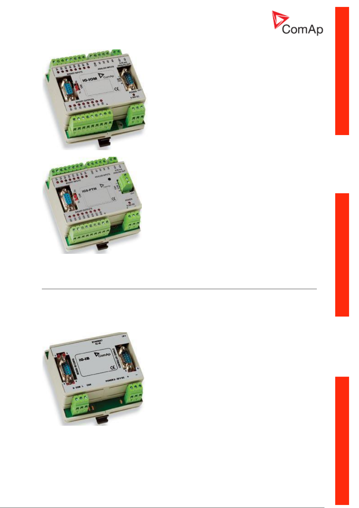
IG IOM/PTM module
IG-IOM and IGS-PTM modules are I/O extension modules equipped with 8 binary inputs, 8 binary
outputs, 4 analogue inputs and one analogue output. The module can be used for AMF25, MRS15,
16, 19 only.
Binary inputs and outputs are configurable the same way like inputs and outputs on iL.
Analogue inputs are configurable like iL with the limitation that the binary and tristate mode
cannot be used on PTM module.
The protection of analogue IOM/PTM inputs is activated by overcrossing the limits, active only
when the engine is running.
IG-IOM analogue inputs are resistive (the same parameters like IL-NT) 0 -2,4 k. The
module IOM is designed for especially VDO resistive sensors.
IGS-PTM analogue inputs are configurable by jumpers to ranges 0-250, 0-100mV, 0-20mA.
The module can be used especially for Pt100 sensors and current sensors. The module PTM
is not suitable for VDO temperature sensor.
Hint:
- For connection details please refer to chapter Extension modules (CAN bus) connection.
- For a description of setting IGS-PTM module with current/voltage sensors please see the Extension
modules manual.
- When module is not configured by LiteEdit SW, controller does not show related values and
setpoints
- If IGS-PTM is not communicating to a controller, ShutDown protection on controller is activated.
InteliLiteNT– AMF20/25, SW version 2.2, ©ComAp – September 2014 19
IL-NT-AMF-2.2-Reference Guide.pdf
Page 20
See the documentation of IGS-PTM for the technical and function description.
IG-IB Internet bridge
IG-IB Internet bridge enables InteliLiteNT for Ethernet/Internet communications. It is connected to
controller via RS232 line.
See InteliCommunication Guide for further details.
InteliLiteNT– AMF20/25, SW version 2.2, ©ComAp – September 2014 20
IL-NT-AMF-2.2-Reference Guide.pdf
Page 21
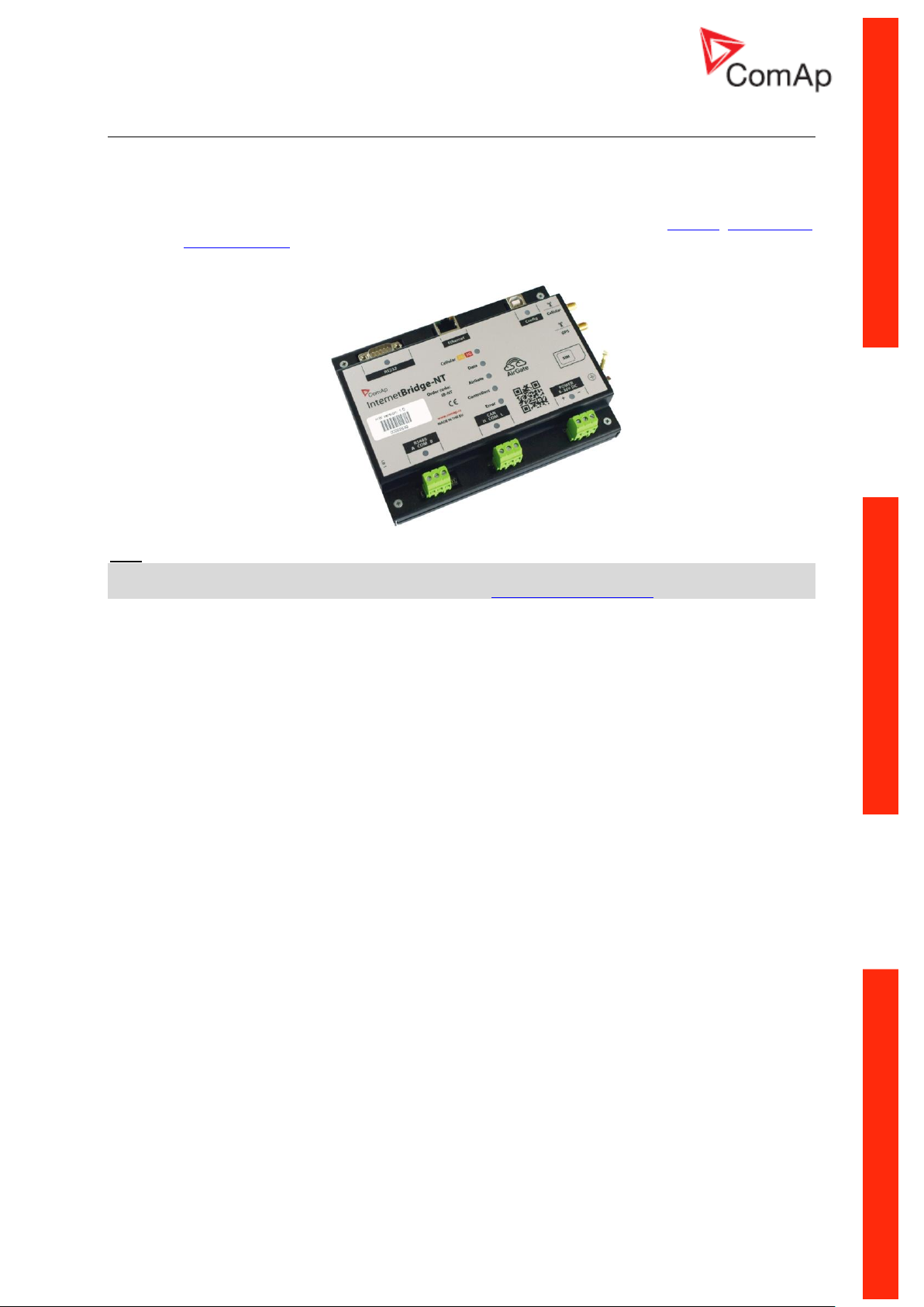
InternetBridge-NT
The InternetBridge-NT (IB-NT) is a communication module that allows connection of a single controller
as well as a whole site to the internet or a Local Area Network. The internet connection can be
enabled via the built-in cellular modem supporting 2G and 3G networks or via Ethernet cable.
For InteliLiteNT the following functions are available:
- Direct Ethernet connection to ComAp configuration and monitoring tools (LiteEdit, InteliMonitor
or WebSupervisor)
- AirGate support
- Web interface
Hint:
Support of InteliLiteNT controllers is in IB-NT 1.2 SW and newer.
For further information and options that can be set, see IB-NT Reference Guide.
InteliLiteNT– AMF20/25, SW version 2.2, ©ComAp – September 2014 21
IL-NT-AMF-2.2-Reference Guide.pdf
Page 22
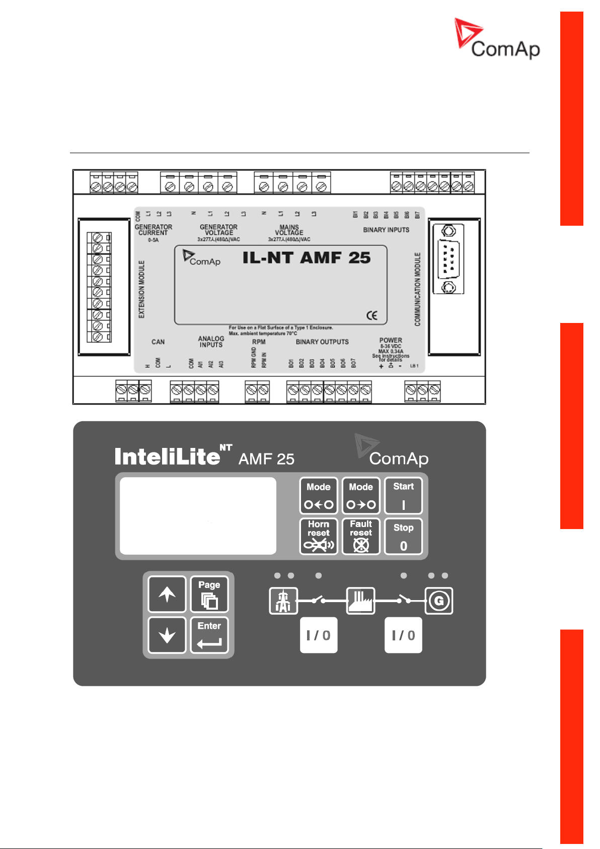
IL-NT Terminals
IL-NT terminals and front face
InteliLiteNT– AMF20/25, SW version 2.2, ©ComAp – September 2014 22
IL-NT-AMF-2.2-Reference Guide.pdf
Page 23

Installation
Mounting
The controller is to be mounted onto the switchboard door. Requested cutout size is 172x112mm. Use
the screw holders delivered with the controller to fix the controller into the door as described on
pictures below. Recommended tightening torque is 0,15 – 0,2 Nm.
WARNING! When mounted in plastic door or box, or sheetmetal door thinner than 2 mm, the
tightening torque must be reduced. If sufficient sealing is not achieved at tightening torque of
approx 0,1 Nm, further tightening may be counterproductive due to rising deformation of the
door. Additional sealing or sealing with silicone should be used if necessary.
InteliLiteNT– AMF20/25, SW version 2.2, ©ComAp – September 2014 23
IL-NT-AMF-2.2-Reference Guide.pdf
Page 24
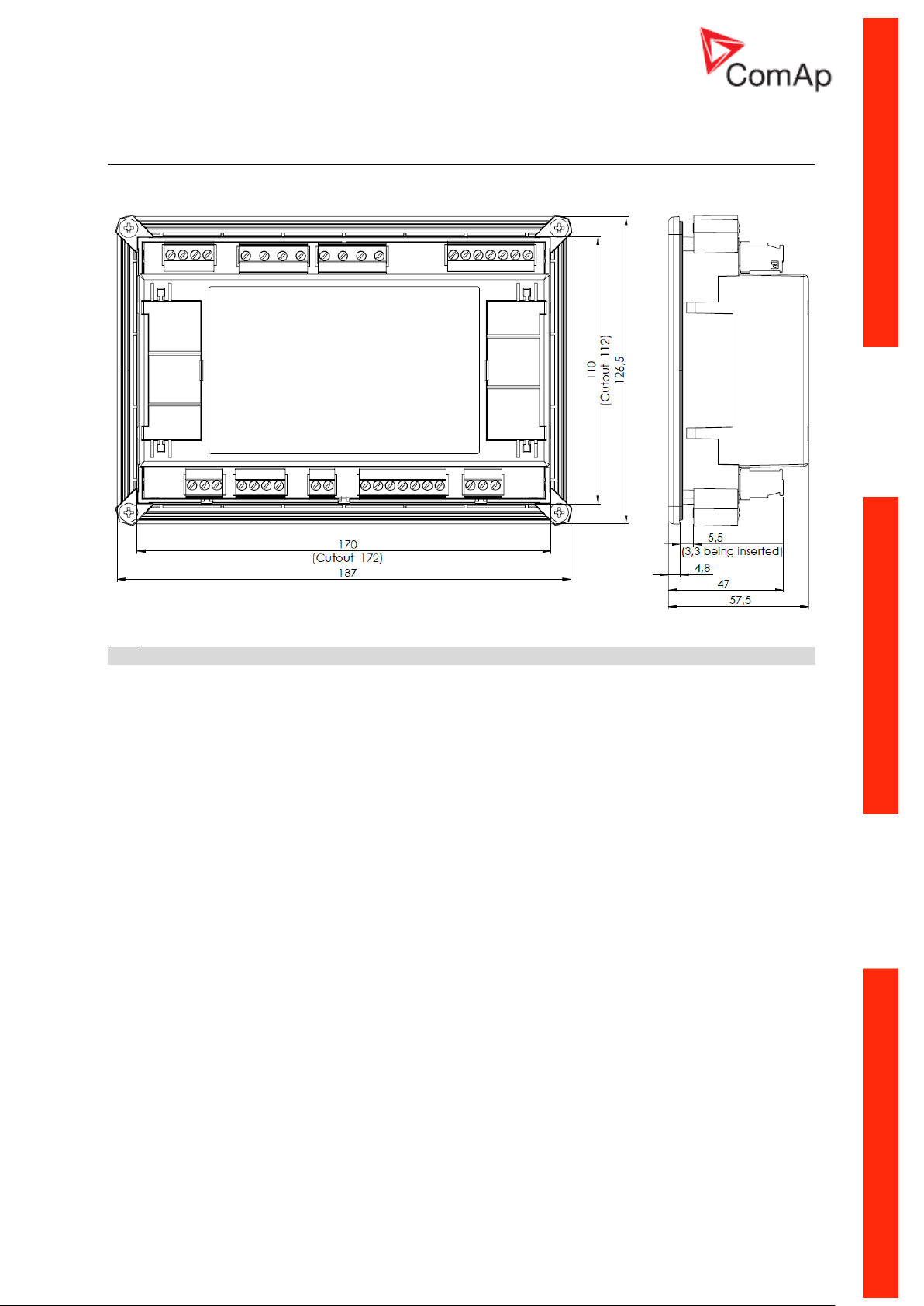
Dimensions
Hint:
Recommended mounting cutout size is 172 x 112 mm
InteliLiteNT– AMF20/25, SW version 2.2, ©ComAp – September 2014 24
IL-NT-AMF-2.2-Reference Guide.pdf
Page 25

Recommended Wiring
AMF – Wiring Diagram
Hint:
MCB and GCB is recommended to be mechanically interlocked.
It is possible to start Volvo and Scania engines via CAN bus. See Engines started via CAN bus.
InteliLiteNT– AMF20/25, SW version 2.2, ©ComAp – September 2014 25
IL-NT-AMF-2.2-Reference Guide.pdf
Page 26
Stand-by Applications
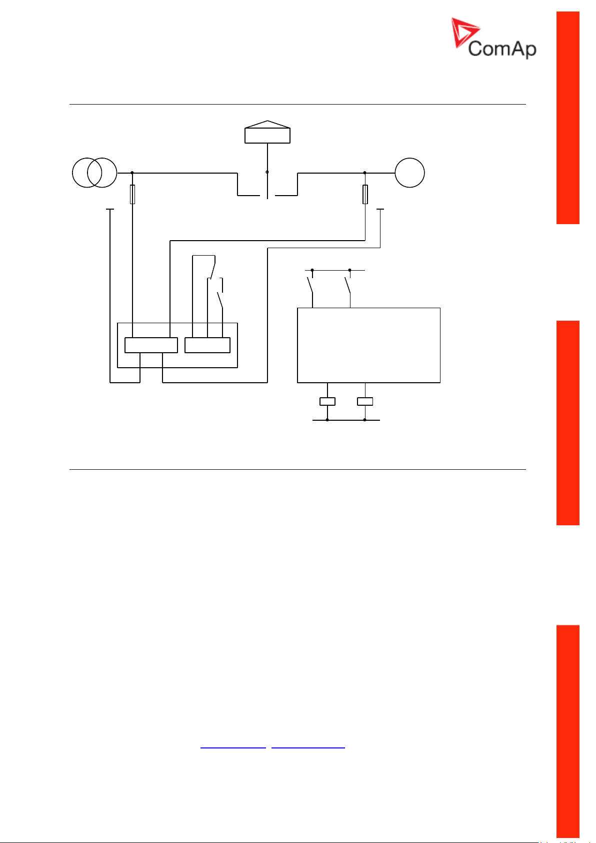
FEEDBACK
+24V(12V)
MCGC
K3
GCB
CLOSE/OPEN
GC
MC
MCB
G~
GCB
MCB
FEEDBACK
CLOSE/OPEN
0V
MC
T
GC
K3
GC
LOAD
MC
K4
K4
FEEDBACK
+24V(12V)
ATS
K3
GCB
MCB
G~
GCB
T
CLOSE/OPEN
ATS
0V
ATS
LOAD
FEEDBACK
CLOSE/OPEN
MCB
K3
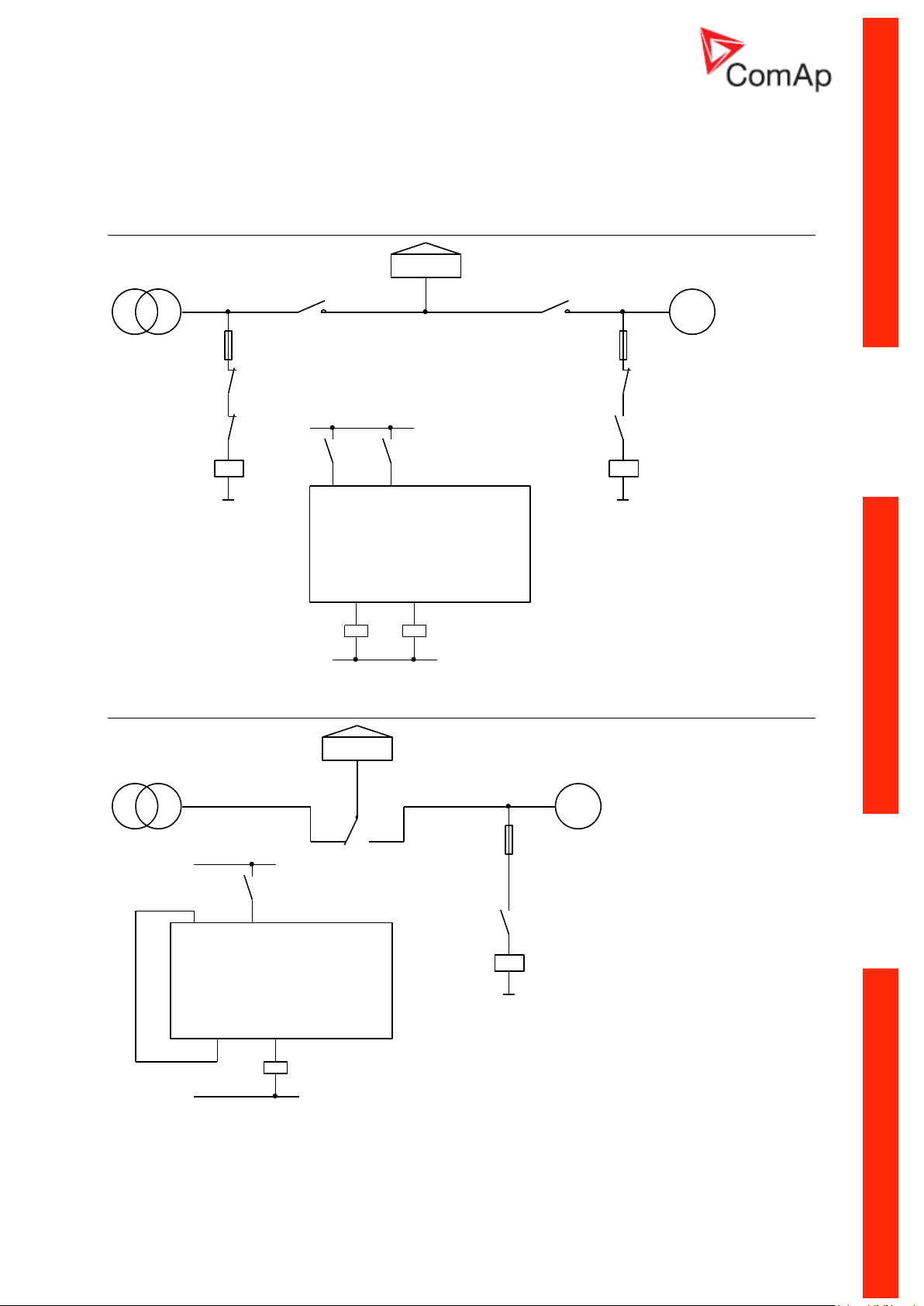
Contactors (set point MCB Logic = “CLOSE-OFF”)
ATS with two stable positions (set point MCB Logic = “CLOSE-ON”)
InteliLiteNT– AMF20/25, SW version 2.2, ©ComAp – September 2014 26
IL-NT-AMF-2.2-Reference Guide.pdf
Page 27
ATS with three stable positions
MCB
FEEDBACK
ATS ll
G~
ATS l
CLOSE/OPEN
K4
0V
K4
T
+24V(12V)
LOAD
GCB
FEEDBACK
K3
MCB
ATS
l 0 ll
CLOSE/OPEN
GCB
K3
ATS
(set point MCB Logic = “CLOSE-OFF”)
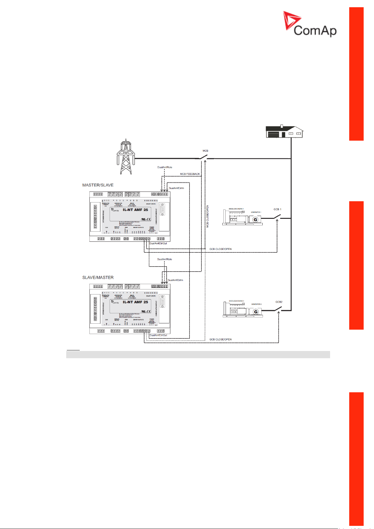
Dual Mutual Standby (Dual AMF) application
Dual AMF is system of two mutual stand-by gen-sets, which switches in supplying the load. Usual
work operation is that after mains fails, first genset starts, takes the load and works for dedicated time
interval, e.g. 6 hours. Than it hand over the load to other gen-set, which runs for another 6 hours. This
operation system continues as long as Mains is failed. Transfer of load from one gen-set to other one
is with blackout.
System works for two gensets with IL-NT-AMF25 controllers. One controller is Master and
second is Slave. Other models of IL-NT are not supported.
System needs one binary input and one binary output in each controller.
System works only in AUT mode
For correct operation both controllers have to have set identical times/delays for mains
protections, mains return delays and other delays in setpoint group AMF Settings.
Mechanical interlock between GCB of one gen-set, GCB of second gen-set and MCB breaker
is required due to safety reasons.
Detailed description:
There is a basic communication interface between Master and Slave controller realized by
interconnection of two wires (DualAMFCtrlIn, DualAMFCtrlOut) on both.
InteliLiteNT– AMF20/25, SW version 2.2, ©ComAp – September 2014 27
IL-NT-AMF-2.2-Reference Guide.pdf
Page 28

Binary input DualAMFCtrlIn and binary output DualAMFCtrlOut adjust their function automatically
based on fact if there are used in Master or in Slave controller.
Master controller has information about Slave controller and when Slave failure or cannot work the
Master will substitute it.
AMF start of Slave controller can be blocked by Master but when Master controller has failure or
cannot work the Slave will substitute it.
When there is incorrect wiring or only one controller is configured as Master or Slave than the
controller will display "DAMF Disconnect" in alarm list.
In case of incorrect configuration (two Masters, two Slaves, both controllers are not in AUT mode) the
controller will display "DAMF ConfigError" in alarm list.
When there is any problem with Slave controller Master will display "DAMFSlaveDown" in alarm list.
Every time when any Alarm related to DAMF function is occurring both of the controllers are switched
to normal AMF operation. That meaning that at least one of the controllers will be able to supplying the
load until failure on both of them.
To decide which genset should start in case of mains fail, there is rule that if mains fails in time period
00:00AM – 11:59AM, than Master will start and take the load. If mains will fail in period 12:00PM –
23:59PM, than Slave will start and take the load.
Master controller will prevent unnecessary blackout in case, when it is over 12:00 AM (Slave starting
period), and Master is already supplying load, but not in AUT mode with DualAMF function enabled,
and mode is changed to AUT. Or if Master is already supplying load in AUT, and it is switched to
DualAMF operation after 12AM (in Slave’s starting period).
Setpoint “MCB Opens On” has to be set to MAINSFAIL. Otherwise system would not correctly work if
Slave would start to stand-by as first. Master would not know when to open MCB breaker.
In case one gen-set should run in stand-by, but it fails, the other gen-set runs instead. After failed genset recovers there is 60s delay for load transfer back to this gen-set.
Setpoints related to Dual AMF function are located in "AMF Settings" group.
Setpoint "DualAMFRole" with settings [MASTER, SLAVE] is determining if controller behaves as
Master or Slave in Dual AMF system. One controller has to be set to MASTER and second as SLAVE,
for correct function of system.
Binary input "DualAMFRole" can help in switching roles of both gen-sets. Both gen-sets can be easily
transformed from Slave to Master and vice versa. Log1 = MASTER, Log 0 = SLAVE. Binary input has
higher priority over manual setting of setpoint. If binary input is configured, manual change of setpoint
is disabled.
Setpoint „DualAMFTime“ control time period of gen-sets switching in supplying the load. Settings are
[1..24], step = 1 hour. Default setting is 6 hours. This timer is reset when load is transferred back to
healthy mains
Example of setting the Dual AMF function:
1- Prepare two IL-NT-AMF25 controllers. Copy the identical configurations to both of them.
2- Use wiring with mechanical/electrical interlock between all breakers (GCB1, GCB2 and MCB)
3- Configure one binary input on each controller as DualAMFCtrlIn.
4- Configure one binary output on each controller as DualAMFCtrlOut.
5- Interconnect DualAMFCtrlOut from one controller with DualAMFCtrlIn on second controller.
Interconnect DualAMFCtrlOut from second controller with DualAMFCtrlIn on first controller. So
you have two wires interconnecting both controllers.
InteliLiteNT– AMF20/25, SW version 2.2, ©ComAp – September 2014 28
IL-NT-AMF-2.2-Reference Guide.pdf
Page 29
6- Set setpoint “MCB Opens On” to MAINSFAIL on both controllers.
7- Set „DualAMFTime“ to time period in which you wish to switch gensets in supplying the load.
For example 6 hours. Make this setting on Master controller. Only Master controller controls
this timer.
8- Set "Operation Mode" to MASTER on first controller and to SLAVE on second controller.
9- Change the mode of both controllers to AUT.
10- System is now ready for DualAMF function.
Wiring of system with selectable MASTER and SLAVE role settings:
Hint:
GCB and MCB breakers feedbacks are recommended, but not required.
InteliLiteNT– AMF20/25, SW version 2.2, ©ComAp – September 2014 29
IL-NT-AMF-2.2-Reference Guide.pdf
Page 30
Getting Started
How to install
During the configuration of controller or setpoints changes is required a password to the
controller. The default password from ComAp is “0”.
General
To ensure proper function:
Use grounding terminals.
Wiring for binary inputs and analog inputs must not be run with power cables.
Analog and binary inputs should use shielded cables, especially when length >3m.
Hint:
Beware of heavy harnesses hanging down from controller terminals. Harnesses must be
tightened to panel doors or other suitable place as close to controller as possible.
Wiring
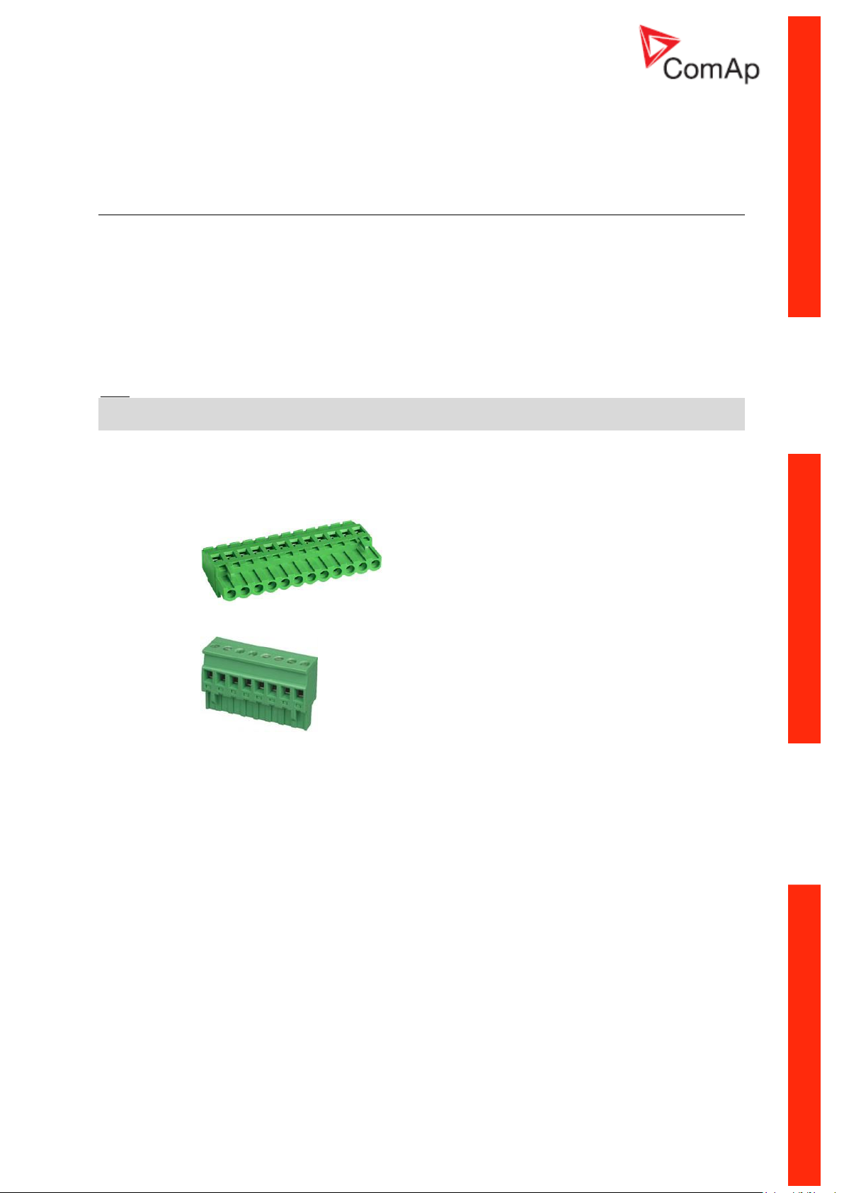
Tightening torque, allowable wire size and type, for the Field-Wiring Terminals:
Based on terminal type:
PA256:
For field type terminals:
For Mains(Bus) Voltage and Generator Voltage terminals
Use copper conductors only.
Specified tightening torque 0,5Nm (4,4 In-lb)
2EDGK:
Specified tightening torque 0,4Nm (3,5 In-lb)
Use only diameter 2,0-0,5mm (12-26AWG) conductor, rated for 75°C minimum.
Use only diameter 2,0-0,5mm (12-26AWG) conductor, rated for 90°C minimum.
Grounding
The shortest possible piece of wire should be used for controller grounding.
Use cable min. 2,5mm2
Brass M4x10 screw with star washer securing ring type grounding terminal shall be used.
The negative “-“ battery terminal has to be properly grounded.
Switchboard and engine has to be grounded in common spot. Use as short as possible cable
to the grounding point.
Power supply
To ensure proper function:
Use min. power supply cable of 1.5mm2
InteliLiteNT– AMF20/25, SW version 2.2, ©ComAp – September 2014 30
IL-NT-AMF-2.2-Reference Guide.pdf
Page 31

Maximum continuous DC power supply voltage is 36VDC.The InteliLite’s power supply terminals are
protected against large pulse power disturbances. When there is a potential risk of the controller
being subjected to conditions outside its capabilities, an outside protection device should be used.
It is necessary to ensure that potential difference between generator current COM terminal and
battery “-” terminal is maximally ± 2V. Therefore is strongly recommended to interconnect
these two terminals together.
Hint:
The InteliLite controller should be grounded properly in order to protect against lighting strikes!!
The maximum allowable current through the controller’s negative terminal is 4A (this is dependent on
binary output load).
For the connections with 12VDC power supply, the InteliLiteNT includes internal capacitors that allow
the controller to continue operation during cranking if the battery voltage dip occurs. If the voltage
before dip is 10V, after 100ms the voltage recovers to 7 V, the controller continues operating. During
this voltage dip the controller screen backlight can turn off and on but the controller keeps operating.
It is possible to further support the controller by connecting the external capacitor and separating
diode or I-LBA module:
The capacitor size depends on required time. It shall be approximately thousands of microFarads.
The capacitor size should be 5 000 microFarad to withstand 150ms voltage dip under following
conditions:
Voltage before dip is 12V, after 150ms the voltage recovers to min. allowed voltage, i.e. 8V
Hint:
Before the battery is discharged the message "Low BackupBatt" appears.
InteliLiteNT– AMF20/25, SW version 2.2, ©ComAp – September 2014 31
IL-NT-AMF-2.2-Reference Guide.pdf
Page 32

+
-
T1A
IL-NT
+
-
Battery
HUGE
LOADS
STARTER
Or by connecting special I-LBA Low Battery Adaptor module:
The I-LBA module ensures min. 350ms voltage dip under following conditions:
RS232 and other plug-in module is connected.
Voltage before dip is 12V and after 350ms the voltage recovers to min. allowed voltage 5V.
The I-LBA enables controller operation from 5VDC (for 10 to 30 sec).
The wiring resistance from battery should be up to 0.1 Ohm for I-LBA proper function.
Hint:
I-LBA may not eliminate voltage drop when used with low temperature (-40°C) version of controller
and display heating element is on (below 5°C). Current drain of heating element exhausts LBA
capacitors very fast.
Power supply fusing
A one-amp fuse should be connected in-line with the battery positive terminal to the controller and
modules. These items should never be connected directly to the starting battery.
Fuse value and type depends on number of connected devices and wire length.
Recommended fuse (not fast) type - T1A. Not fast due to internal capacitors charging during
power up.
InteliLiteNT– AMF20/25, SW version 2.2, ©ComAp – September 2014 32
IL-NT-AMF-2.2-Reference Guide.pdf
Page 33

Binary output protections
Hint
Do not connect binary outputs directly to DC relays without protection diodes, even if they are not
connected directly to controller outputs.
InteliLiteNT– AMF20/25, SW version 2.2, ©ComAp – September 2014 33
IL-NT-AMF-2.2-Reference Guide.pdf
Page 34

Magnetic pick-up
+
Battery
-
iL
GAC
Speed Control Unit
ESD 5500
MAGNETIC
PICK-UP
C
D
a
b
Signal
Signal
+
+-
-
Power
Supply
Power
Supply
To ensure proper function:
Use a shielded cable
Be aware of interference signal from Speed governor when one speed pick-up is used.
If engine will not start:
- Check ground connection from pick-up to controllers, eventually disconnect ground connection
to one of them
- Galvanically separate InteliLite RPM input using ComAp separation transformer RPM-ISO
(1:1)
- Use separate pick-up for Speed governor and InteliLiteNT
Hint:
In some cases the controller will measure a RPM value even though the gen-set is not running:
RPM is measured from the generator voltage (Gear Teeth = 0)
IL-NT is measuring some voltage value on input terminals due to open fusing.
If RPM > 0 the controller will be put into a Not ready state and the engine will not be allowed to start.
Current measurement
The number of CT’s is automatically selected based on selected value of setpoint ConnectionType
[3Ph4Wire / 3Ph3Wire / Split Ph / Mono Ph].
Hint:
Further information about measurement limits are at setpoint CT Ratio [/5A] description in chapter
Setpoints - Basic Settings.
Generator currents and power measurement is suppressed if current level is bellow <1% of CT
range.
To ensure proper function:
Use cables of 2,5mm
Use transformers to 5A
Connect CT according to following drawings:
Three phase application:
InteliLiteNT– AMF20/25, SW version 2.2, ©ComAp – September 2014 34
IL-NT-AMF-2.2-Reference Guide.pdf
2
Page 35

It is necessary to ensure that potential difference between generator current COM terminal and
battery “-” terminal is maximally ± 2V. Therefore is strongly recommended to interconnect
these two terminals together.
Single phase application:
Connect CT according to following drawings. Terminals L2l and L3l are opened.
CT location
There are two options of CT location.
a) Load
b) Gen-Set
New setpoint CT Location for AMF20 and AMF25 controllers is placed in group Basic Setting.
According to the connection it is possible to set CT location: Load or Gen-Set. When CT Location is
set to Load and MCB is closed the controller will display on Mains screen current value. The statistics
now contain Mains kWh, Mains kVArh, Genset kWh, Genset kVArh.
Hint:
The current measurement protections are active only when the Genset is running.
Hint:
If the CT Location is set to Load the Short Crct BOC protection is enabled only when GCB is closed.
InteliLiteNT– AMF20/25, SW version 2.2, ©ComAp – September 2014 35
IL-NT-AMF-2.2-Reference Guide.pdf
Page 36

Earth Fault measurement (module)
The Earth Fault protection is done by extension module IC-NT CT-BIO7.
Technical characteristics
- Input current range up to 5 A (IC-NT CT-BIO7)
- Measurement range from 1 to 500 A
- Operating frequency 50 or 60 Hz
- Tripping current software programmable from 1 to 500 A or DISABLED
- Tripping delay software programmable from 0,03 to 5 seconds
- Included seven binary inputs or seven binary outputs (IL-NT-CT-BIO7)
Hint:
For more technical details see IC-NT CT-BIO7 interface.
Hint:
For more information about the application settings see EarthFaultProt setpoint group
Operating principle
When the measured current exceeds the set value, this indicates that part of the current is dispersed
to earth and after the set Earth Fault Del then Earth Fault Sd protection and AL EarthFault output are
activated. Earth Fault protection is not active when gen-set does not run and also when EF Protection:
DISABLED.
InteliLiteNT– AMF20/25, SW version 2.2, ©ComAp – September 2014 36
IL-NT-AMF-2.2-Reference Guide.pdf
Page 37

IC-NT CT-BIO7 wiring
Voltage measurement and generator connection types
There are 4 voltage measurement ConnectionType (setpoint ConnectionType [3Ph4Wire /
3Ph3Wire / Split Ph / Mono Ph]) options, every type matches to corresponding generator connection
type.
The generator protections are evaluated from different voltages based on ConnectionType setting:
3W 4Ph – Ph-Ph voltage
3W 3Ph – Ph-Ph voltage
Split Ph – Ph-N voltage
Mono Ph – Ph-N voltage
ConnectionType: 3 Phase 4 Wires
3 Phase 4 Wires - STAR Connection Three phase “wye” measurement – 3PY
InteliLiteNT– AMF20/25, SW version 2.2, ©ComAp – September 2014 37
IL-NT-AMF-2.2-Reference Guide.pdf
Page 38
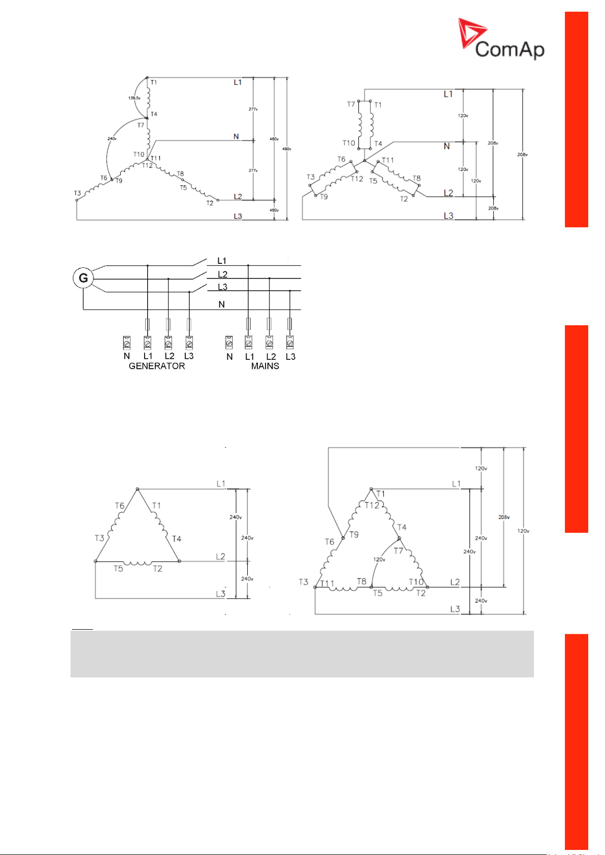
ConnectionType: 3 Phase 3 Wires
3 Phase 3 Wires
– DELTA Connection
Hint:
Only L1, L2 and L3 wires should be connected. In case of HI-LEG (WILD-LEG, RED-LEG) DELTA
connection the N (neutral)
wire (in the diagram connected between T6 and T9) has to be disconnected.
No separation transformers for three wires voltage connection (without N) are needed.
– HI-LEG (WILD-LEG, RED-LEG) DELTA
Connection
InteliLiteNT– AMF20/25, SW version 2.2, ©ComAp – September 2014 38
IL-NT-AMF-2.2-Reference Guide.pdf
Page 39

ConnectionType: Split Phase
Split Phase
– DOUBLE DELTA Connection – ZIG ZAG (DOG LEG) Connection
ConnectionType: Mono Phase
Single-phase measurement – 1PH
Hint:
There has been a change in wiring of monophase at voltage terminals between firmware IL-NT1.4 and
IL-NT1.5! Picture above shows connection for IL-NT 1.5. Wiring for older firmwares is described in
older IL-NT manuals, line L1 was connected to all three terminals L1,L2 and L3.
Mono Phase – MONOPHASE Connection
Hint:
InteliLiteNT– AMF20/25, SW version 2.2, ©ComAp – September 2014 39
IL-NT-AMF-2.2-Reference Guide.pdf
Page 40

Switchboard lighting strike protection according standard regulation is expected for all 4 connection
Analog input item
LiteEdit Possibility
Type
Type
Not used
Alarm
Monitoring
Analog input isn’t used
Analog is measured and used
for protection
Analog is only measured and
not used for protection
Analog input name
Name
Up to 14 ASCII characters
Config of input
Config
Analog
Binary (not supp. by PTM)
Tri-state (not supp. by PTM)
ECU
Analog measuring in specified
range.
Binary: open/close - threshold
750 .
Three-state: open/close threshold 750 ,
Failure <10 or > 2400
Value is read from ECU
Physical dimension
Dim
bar,%,°C, …
Up to 4 ASCII characters
(Valid only for analog inputs)
Polarity
Contact type
NC
NO
Valid only for binary and threestate inputs
Valid only for binary and threestate inputs
Protection direction
Protection
Over
Overstep. Sensor Fail does
not activate protection.
Over+Fls
Overstep and Sensor Fail
activates protection.
Under
Under step. Sensor Fail does
not activate protection.
Under+Fls
Under step and Sensor Fail
activates protection.
Sensor characteristic
Sensor
Predefined user curves
User changeable and
configurable
Resolution
Resolution
0 – 0,00001
Sensor resolution
(Valid only for analog inputs)
types!!!
Hint:
Phase sequence check is not possible to evaluate under voltage 50V what causes that if measured
voltage 50V is within the allowed range, controller will not allow to close the GCB, even if relevant LED
diode on front panel of IL-NT lits.
Analog inputs
Three analog inputs are available on the IL-NT. First analog input is fixed to be used for engine Oil
Pressure.
Configuration
Each analog input can be configured by LiteEdit software in following way (First analog input is
dedicated to engine Oil pressure).
Each Analog input has separate set points for two level alarm setting. Analog input alarm levels and
delay adjust in Extension I/O and Engine Protect group.
Hint:
Description of Sensor fail evaluation can be found in chapter Alarm Management, article Sensor Fail
(FLS).
InteliLiteNT– AMF20/25, SW version 2.2, ©ComAp – September 2014 40
IL-NT-AMF-2.2-Reference Guide.pdf
Page 41

Connection of IL-NT analog inputs
AI1AI2
3 x RESISTIVE
SENSOR
AI3
COM
- POWER
Standard connection of three resistive sensors
to analog inputs.
2
x
470
COM
-
POWER
AI1
AI2
AI3
Mixed connection of InteliLite analog inputs:
AI1 – binary input
AI2 – three state input
AI3 – analog resistive input
Hint:
Description of analog inputs with COM terminal and 4 pins relates to units with HW version 1.3. Older
HW versions do not have “COM” terminal and use only 3 pins AI1, AI2 and AI3.
Wiring
Wiring diagrams of analog inputs since IL-NT HW 1.3:
WIRING OF ANALOG INPUTS-GROUNDED SENSORS
InteliLiteNT– AMF20/25, SW version 2.2, ©ComAp – September 2014 41
IL-NT-AMF-2.2-Reference Guide.pdf
Page 42

WIRING OF ANALOG INPUTS-ISOLATED SENSORS
Wiring diagrams of analog inputs for IL-NT HW 1.1 and older:
InteliLiteNT– AMF20/25, SW version 2.2, ©ComAp – September 2014 42
IL-NT-AMF-2.2-Reference Guide.pdf
Page 43

Analog inputs are designed for resistive sensors with resistance in range of 0 to 2,4k.
To ensure a proper function use shielded cables, especially for length over >3m.
COM terminal is dedicated to measure ground voltage potential difference between engine and
controller.
As binary input
Open, close state are detected, threshold level is 750 .
InteliLiteNT– AMF20/25, SW version 2.2, ©ComAp – September 2014 43
IL-NT-AMF-2.2-Reference Guide.pdf
Page 44

As three state input
Open, close and failure state are detected. Threshold level is 750 , failure is detected when circuit
resistance is <10 or > 2400 .
Hint:
Protections on binary and three state inputs are following:
IL-NT: AI1 Shutdown IG-IOM: AI1 Shutdown
AI2 Shutdown AI2 Shutdown
AI3 Warning AI3 Shutdown
AI4 Shutdown
Unused analog inputs
Configure Type = Not used
Example of analog input configuration
Configure Engine Temp input for measuring in °C, VDO 40-120°C sensor, range -16 to 120 °C. Alarm
protection level set to 90 °C, shut down level 110 °C.
Start LiteEdit and select – Controller - Configuration – Modify – Engine Temp.
Set configuration for Engine temp analog input:
Type: Selection between Not used and Alarm
“Not used” – analog input isn’t used
”Alarm” – analog input is used
Set to: Alarm
Name: Name of the analog input. Maximally 14 letters.
Set to: Engine Temp
Config: Selection between Analog, Binary Tri-state input.
“Analog” – resistor sensor is connected to Analog input.
“Binary” – open/close contact is connected between Analog input and COM terminal of Analog inputs.
Analog input detects only open/close state.
“Tri-state” – open/close contact is connected parallel to one of two serial resistors between Analog
input and COM terminal of Analog inputs.
Set to: Analog
Alarm Properties: Selection between different direction of protection – Under Limit, Over Limit or
combination with Fail sensor.
“Engine running only” – check this setting if you wish to active protection on analog input only while
engine is running, not, when it stops.
Set to: Over Limit
Contact type: selection of polarity only when analog input is configured as Binary or Tri-state. When
is analog input configured as analog this setting has no sense.
„NC“ – polarity of binary or tri-state input
„NO“ – polarity of binary or tri-state input
Sensor: selection of sensor characteristic
„Unused input“ - when Analog input is not used. On the InteliLite screen is displayed „####“ value, no
alarm is detected.
Default user curves predefined on AI1 – AI3:
„VDO 10 Bar“ – VDO pressure sensor
„VDO 40-120 °C“ – VDO temperature sensor
„VDO level %“ – VDO level sensor
Set to: VDO 40-120 °C
When you choose the predefined or user curve the Sensor Name, Dim and Resolution are set
automatically according to curve, user modification is possible.
InteliLiteNT– AMF20/25, SW version 2.2, ©ComAp – September 2014 44
IL-NT-AMF-2.2-Reference Guide.pdf
Page 45

Sensor Name: Name of used sensor, up to 14 letters can be used.
Analog input
R1
R2
Curve
0 - 10V
150Ω [1%,0,5W]
100Ω [1%,0,5W]
AI 0-10V.CRV
0 - 30V
680Ω [5%,2W]
100Ω [1%,0,5W]
AI 0-30V.CRV
0 - 65V
1500Ω [5%,3W]
100Ω [1%,0,5W]
AI 0-65V.CRV
4 – 20mA
R = 160Ω [1%,0,5W]
AI 4-20mA.CRV
Dim: Name of measured unit (Bar, °C, %, …), up to 4 letters can be used.
Resolution: setting of resolution of measured value.
„0“ - e.g. 360 kPa, 100%, 50 C
„1“ – e.g. 360.0 kPa
„2“- e.g. 360.00 kPa
„3“ - e.g. 360.000 kPa
Set to: 1
When Analog input configuration is finished set the setpoints AI1 Wrn, AI1 Sd, AI1 Del in Engine
Protect group.
Each Analog input has separate triplet of setpoints: Wrn level, Sd level, AI del. Names of these
setpoints are fix defined
Number of decimal points of Wrn level and Sd level is the same as the configured number of decimal
points of measured value.
Analog input extension measurement (0 - 70V, 4 - 20mA)
On each analog input there is a possibility to connect voltage or current output sensor instead of
resistive one. Recommended wiring connection for these measurements are bellow.
Voltage output sensor - connection
Current output sensor – connection
Table with recommended values
InteliLiteNT– AMF20/25, SW version 2.2, ©ComAp – September 2014 45
IL-NT-AMF-2.2-Reference Guide.pdf
Page 46

+
Battery
-
iL
4k7
+
-
Power
Supply
Hint:
Vout [V]
0 1 2 3 4 5 6 7 8 9 10
P [bar]
0
0,6
1,2
1,8
2,4 3 3,6
4,2
4,8
5,4
6
Please note that external resistors disconnection, connection incorrect resistors or input voltage value
during operation may cause an analog input destruction.
Practical example: VDO pressure sensor 0 – 6bar with linear voltage output 0 – 10V
Conversion table
Modify one of analog input in LiteEdit configuration and load curve AI 0-10V.CRV
Than you can change resolution and measured value name witch is default displayed at V (volts).
For example if you have connected pressure sensor and his output voltage is 5V for pressure 3bar
you can change value ‘V’ in column “Dim:” to ‘Bar’ and by sensor specification adjust all corresponding
values in this column. In this case you can change the value at row 6. from 5 to 3.
When you finish with adjusting the values click OK and Write to controller.
Binary inputs and outputs
InteliLiteNT– AMF20/25, SW version 2.2, ©ComAp – September 2014 46
IL-NT-AMF-2.2-Reference Guide.pdf
Page 47

+
Battery
-
iL
LOAD
+
-
Power
Supply
Recommended CAN/RS485 connection
CAN bus connection
The bus has to be terminated by 120 Ohm resistors at both ends.
External units can be connected on the CAN bus line in any order, but keeping line arrangement (no
tails, no star) is necessary.
Standard maximum bus length is 200m
Shielded cable has to be used, shielding has to be connected to PE on one side (controller side).
A) For shorter distances (all network components within one room) – picture 1
Interconnect H and L; shielding connect to PE on controller side
B) For longer distances (connection between rooms within one building) – picture 2
Interconnect H, L, COM; shielding connect to PE in one point
C) In case of surge hazard (connection out of building in case of storm etc.) – picture 3
We recommend to use following protections:
- Phoenix Contact (http://www.phoenixcontact.com):
PT 5-HF-12DC-ST with PT2x2-BE (base element)
- Saltek (http://www.saltek.cz):
DM-012/2 R DJ
Recommended data cables: BELDEN (http://www.belden.com)
A) For shorter distances: 3105A Paired - EIA Industrial RS-485 PLTC/CM (1x2 conductors)
B) For longer distances: 3106A Paired - EIA Industrial RS-485 PLTC/CM (1x2+1 conductors)
C) In case of surge hazard: 3106A Paired - EIA Industrial RS-485 PLTC/CM (1x2+1 conductors)
RS485 connection
The line has to be terminated by 120 Ohm resistors at both ends.
External units can be connected on the RS485 line in any order, but keeping line arrangement (no
tails, no star) is necessary.
Standard maximum link length is 1000m.
Shielded cable has to be used, shielding has to be connected to PE on one side (controller side).
A) For shorter distances (all network components within one room) – picture 1
interconnect A and B; shielding connect to PE on controller side
B) For longer distances (connection between rooms within one building) – picture 2
interconnect A, B, COM; shielding connect to PE in one point
C) In case of surge hazard (connection out of building in case of storm etc.) – picture 3
InteliLiteNT– AMF20/25, SW version 2.2, ©ComAp – September 2014 47
IL-NT-AMF-2.2-Reference Guide.pdf
Page 48

We recommend to use following protections:
CAN1
H
COM
L
CAN2
120
1.iS-CU
Addr.: 1Addr.: 1
CAN1 CAN1
8.iS-AIN
Addr.: 8
7.iS-BIN
Addr.: in13
out7
CAN1 CAN1
1.iS-AIN
Addr.: 1
120
1.iS-BIN
Addr.: in1
out1
CAN1CAN2
2.iS-CU
120
H
COM
L
H
COM
L
H
COM
L
H
COM
L
H
COM
L
H
COM
L
H
COM
L
H/A
L/B
COM
120 Ω
PT5-HF-12DC-ST (CAN)
PT5HF-5DC-ST (RS485)
H/A
L/B
COM
120 Ω
OUT
IN
OUT
1
5
7
9
3
11
2
6
8
12
10
4
IN
1
5
7
9
3
11
2
6
8
12
10
4
- Phoenix Contact (http://www.phoenixcontact.com):
PT 5-HF-5DC-ST with PT2x2-BE (base element)
(or MT-RS485-TTL)
- Saltek (http://www.saltek.cz):
DM-006/2 R DJ
Recommended data cables: BELDEN (http://www.belden.com)
A) For shorter distances: 3105A Paired - EIA Industrial RS-485 PLTC/CM (1x2 conductors)
B) For longer distances: 3106A Paired - EIA Industrial RS-485 PLTC/CM (1x2+1 conductors)
C) In case of surge hazard: 3106A Paired - EIA Industrial RS-485 PLTC/CM (1x2+1 conductors)
Picture 1 - shorter distances (all network components within one room)
Picture 2 - longer distances (connection between rooms within one building)
Picture 3 - surge hazard (connection out of building in case of storm etc.)
InteliLiteNT– AMF20/25, SW version 2.2, ©ComAp – September 2014 48
IL-NT-AMF-2.2-Reference Guide.pdf
Page 49

Extension modules (CAN bus) connection
CAN H
CAN L
IGL-RA15 (optional)
CAN H
CAN L
or
CAN L
CAN H
COM
IGS-PTM (optional)
CAN L
CAN H
COM
IG-IOM (optional)
5
9
CANL
CANH
120 ohm
EXTENSION
MODULES
H
L
120ohm
10 ohm
15nF
COM
IL-NT
EXTENSION
MODULES
CAN H
CAN L
IGL-RA15
(optional)
Engine
Electronic Control Unit
CAN H
CAN L
CAN H
CAN L
H
L
or
120ohm
CANL
CANH
COM
IGS-PTM (optional)
CANL
CANH
COM
IG-IOM (optional)
5
9
CANL
CANH
120 ohm
CAN HI
CAN LO
120ohm
10 ohm
15nF
COM
IL-NT
Connection rules
CAN bus line must be connected in series, from one unit to the next (no star, no cable stubs, no
branches) both ends must be by the 120-ohm (internal or external) resistor terminated. Maximal CAN
bus length is up to 200 meters.
For CAN data cables details see chapter Technical data – Communication interface. CAN cable
shielding connect to IL-NT COM terminal.
IL-NT contains internal fix 120-ohm resistor and must be located on the CAN bus end. New units with
HW version 1.3 have terminating resistor jumper located at CAN terminal.
New IG-IOM and IGS-PTM units contain internal jumper removable 120-ohm resistor (in older IOM
types are fix resistors). To be sure check resistor presence by ohmmeter. Unit with internal resistor
connect to the end of CAN line.
Following connections are supported (IOM, PTM, ECU order is not important).
IL- NT – IG-IOM
IL- NT – IGS-PTM
IL- NT – IGL-RA15
IL- NT – IG-IOM – IGL-RA15
IL- NT – IGS-PTM – IGL-RA15
It is possible to connect only one IG-IOM or IGS-PTM and one IGL-RA15 to IL-NT.
Use button in LiteEdit configuration window to activate CAN (J1939) interface with ECU.
InteliLiteNT– AMF20/25, SW version 2.2, ©ComAp – September 2014 49
IL-NT-AMF-2.2-Reference Guide.pdf
Page 50

Inputs and Outputs
Name
14 characters ASCII string
Contact type
NC
Normally closed
NO
Normally opened
Alarm type
Warning
BOC
Shut down
Alarm active
All the time
Valid if checkbox “Engine running
only” is not checked
Engine running only
Valid if checkbox “Engine running
only” is checked
For Inputs/Outputs overview table see chapter Technical Data.
Hint:
Any Binary input or output can be configured to any IL-NT controller terminal or changed to different
function by LiteEdit software. There is fix 1 sec delay when any binary input is configured as
protection.
Binary inputs IL-NT - default
BI1 GCB Feedback
BI2 MCB Feedback
BI3 Emergency Stop
BI4 Access Lock
BI5 Remote OFF
BI6 Remote TEST
BI7 Sd Override
Binary inputs – list
Not Used
Binary input has no function. Use this configuration when Binary input is not connected.
Alarm
If the input is closed (or opened) selected alarm is activated.
Binary Alarm configuration items
GCB Feedback
Use this input for indication, whether the generator circuit breaker is open or closed.
Hint:
IL-NT controller can work even without breaker feedbacks, in this case do not configure the feedback
to binary inputs.
For more details see chapters Circuit breakers timing and GCB, MCB fail detection.
InteliLiteNT– AMF20/25, SW version 2.2, ©ComAp – September 2014 50
IL-NT-AMF-2.2-Reference Guide.pdf
Page 51

MCB Feedback
This input indicates whether MCB is closed or opened.
Hint:
IL-NT controller can work even without breaker feedbacks, in this case do not configure the feedback
to binary inputs.
For more details see chapters Circuit breakers timing and GCB, MCB fail detection.
Rem Start/Stop
External request for engine run. AUT mode only.
Hint:
If the binary input Rem Start/Stop is active and mains failure occurs, the MCB breaker opens, and
after FwRet Brk delay the GCB breaker is closed. Once the mains is OK, the RetTransf delay elapses
and the GCB breaker is opened. Then after FwRet Brk delay is MCB breaker closed. Gen-set remains
running as long as Rem Start/Stop is active.
Emergency Stop
If the input is opened, shut down is immediately activated. Input is inverted (normally closed) in default
configuration.
Hint:
In case of controller hardware or software fail, safe stop of the engine doesn’t have to be ensured. To
back-up the Emergency Stop function it is recommended to connect separate circuit for disconnection
of Fuel Solenoid and Starter signals.
Sd Override
If the input is closed all alarms are disabled except the binary input EMERGENCY STOP and "engine
overspeed protection".
all IL alarms are detected,
IL front panel gen-set RED LED blinks or lights,
alarm is recorded on the IL alarm list screen,
BUT gen-set remains running.
Hint:
Warning Sd Override is indicated in the AlarmList if Sd Override mode is active to inform the operator
that the engine is not protected.
Access Lock
If the input is closed, no setpoints can be adjusted from controller front panel and gen-set mode (OFFMAN-AUT-TEST) cannot be changed.
Hint:
Access Lock does not protect setpoints and mode changing from LiteEdit. To avoid unqualified
changes the selected setpoints can be password protected.
Also the buttons Fault reset, Horn reset are not blocked at all and buttons Start and Stop in MAN
mode are not blocked.
Remote OFF
If closed, IL-NT is switched to OFF mode (there are four modes OFF-MAN-AUT-TEST). When opens
controller is switched back to previous mode.
Hint:
The Remote OFF has higher priority than Remote MAN, AUT, TEST.
InteliLiteNT– AMF20/25, SW version 2.2, ©ComAp – September 2014 51
IL-NT-AMF-2.2-Reference Guide.pdf
Page 52

Hint:
This binary input should be connected to schedule timer switch, to avoid start of engine.
Remote MAN
If the input is active, MAN mode is forced to the controller independently on the position of the MODE
selector.
Hint:
The Remote MAN has higher priority than Remote AUT, TEST.
Remote AUT
If the input is active, AUTO mode is forced to the controller independently on the position of the MODE
selector. If another of „remote“ inputs is active, then the REMOTE AUT input has the lowest priority.
Hint:
The Remote AUT has higher priority than Remote TEST.
Remote TEST
If closed, IL-NT is switched to TEST mode (there are four modes OFF-MAN-AUT-TEST). When opens
controller is switched back to previous mode.
Rem TEST OnLd
Affects the behavior in TEST mode. When input is closed, the controller automatically transfers load
from the mains to the gen-set. Setpoint AMF Settings: ReturnFromTEST must be set to MANUAL.
Load is automatically transferred back to the mains when any gen-set shut down protection activates.
In case AMF Settings: ReturnFromTEST is set to AUTO, then only gen-set is started, but MCB is not
opened and GCB is not closed, except there is a Mains fail. So controller behaves like in common
TEST mode.
For more details see description of the setpoint AMF Settings: ReturnFromTEST [MANUAL /
AUTO].
Hint:
Function Test Onload was changed to combination Remote Test + Rem TEST OnLd.
RemControlLock
If the input is active, setpoints writing or command sending from the external terminal is disabled.
Emergency MAN
If the input is activated the controller behaves like when switched to OFF Mode. Opens all binary
outputs. There is one exception – STOP SOLENOID doesn’t activate on this transition.
Detection of "running" engine and subsequent alarm message "Wrn Stop Fail" is blocked.
The controller shows “EmergMan” state and the engine cannot be started.
Generator current and power measurement is active in this mode, regardless of the actual state of the
engine.
Hint:
The statistical values are not counted when Emergency MAN is activated.
After the input is open again, the controller recovers to previous state and behaves according to the
actual situation.
Function is active in any controller mode.
Start Button
Binary input has the same function as Start Button on the InteliLite front panel. It is active in MAN
mode only.
InteliLiteNT– AMF20/25, SW version 2.2, ©ComAp – September 2014 52
IL-NT-AMF-2.2-Reference Guide.pdf
Page 53

Stop Button
Binary input has the same function as Stop Button on the InteliLite front panel. It is active in MAN
Mode only.
Hint:
Changed function of Stop Button. After the first pressing from running state, there is a standard delay
and controller change state to cooling. After holding the button down for 2 seconds controller goes to
stop state. The same holds true for BI “Stop Button”.
FaultResButton
Binary input has the same function as Fault Reset button on the InteliLite front panel.
Hint:
This binary input FaultResButton must not be permantly activated. It would discard some controller
protections.
HornResButton
Binary input has the same function as Horn reset button on the InteliLite front panel.
GCB Button
Binary input has the same function as GCB button on the InteliLite front panel. It is active in MAN
mode only.
MCB Button
Binary input has the same function as MCB button on the InteliLite front panel. It is active in MAN
mode only.
MainsFailBlock
If the input is closed, the automatic start of the gen-set at Mains failure is blocked. In case of running
gen-set in AUT mode, timer ReturnDel is started and when it elapse GCB is opened, gen-set goes to
cooling procedure and stops. When GCB is opened after TransferDel the MCB is closed.
Hint:
This input simulates healthy Mains.
AMF StartBlock
This binary input can allow or block the AMF start. When the AMF start is blocked and Mains Fail will
come in AUT mode than the MCB breaker will stay closed.
DualAMFRole
This binary input could be used for switching between Master and Slave controller in Mutual Standby
Application (Dual AMF).
DualAMFCtrlIn
Control input for Mutual Standby Application. This binary input of controller 1 must be configured and
interconnected with binary output DualAMFCtrlOut of controller 2 for correct Mutual Standby function.
Hint:
More information about Dual mutual Standby is in chapter Stand-by Application.
Lang Selection
Not configured
Language selection is done only through the controller display. Pressing ENTER and PAGE buttons
concurrently and then only PAGE button separately.
InteliLiteNT– AMF20/25, SW version 2.2, ©ComAp – September 2014 53
IL-NT-AMF-2.2-Reference Guide.pdf
Page 54

Configured on any binary input
If the input is opened the first (default) language is active and if the input is closed then the second
language is active. In case there is more languages available in the controller it is not possible to
select any other language even through the controller display.
AMF Function
This BI can switch controller function between AMF and MRS.
Hint:
Binary input “AMF function” has higher priority than the setpoint Operation Mode in AMF Settings.
Alt. Config.
This BI can switch between basic controller settings in Alternate Cfg setpoint group.
Manual Idle
This binary input will affect the controller behavior only when the engine is running in MAN mode.
When the input is activated in MAN mode
If GCB is closed the controller will open it.
The controller will try to switch the engine to Idle speed (request to Idle speed is sent to ECU
and LBO Idle/Nominal is activated).
The LCD will indicate Manual Idle state
Generator protections are deactivated
GCB is locked in open position
When the input is deactivated the controller continues in the same way as during starting sequence by
Idle Time.
Hint:
Binary Input GCB Feedback and Binary Output GCB Open/Close must be configured. Otherwise Idle
speed function will not be activated!
Binary outputs IL-NT - default
BO1 Starter
BO2 Fuel Solenoid
BO3 GCB Close/Open
BO4 MCB Close/Open
BO5 Prestart
BO6 Ready To Load
BO7 Alarm
Hint:
The description of binary outputs of a controller relates also to IOM/PTM modules.
InteliLiteNT– AMF20/25, SW version 2.2, ©ComAp – September 2014 54
IL-NT-AMF-2.2-Reference Guide.pdf
Page 55

Binary outputs - list
Not Used
Output has no function.
Starter
The closed relay energizes the starter motor.
The relay opens if:
the “firing” speed is reached or
maximum time of cranking is exceeded or
request to stop comes up
Fuel Solenoid
Closed output opens the fuel solenoid and enables the engine start.
The output opens if:
EMERGENCY STOP comes or
Cooled gen-set is stopped or
in pause between repeated starts
Stop Solenoid
The closed output energizes stop solenoid to stop the engine. This output is deactivate 10s after the
still engine conditions are evaluated.
Hint:
For more detail see chapter “Stop engine” conditions in chapter Gen-set Operation States
Hint:
The engine can be started anytime, if all symptoms say the engine is steady regardless of the fact the
Stop Solenoid can still be active (in that case it is deactivated before cranking).
Stop Pulse
Output is active for 1 second after Stop Solenoid output activation. This signal is sent to ECU in case
of engine stop request.
Ignition
The output closes after reaching value of crank RPM, fixed 30RPM. Opens after stopping of the
engine or in pause during repeated start.
Prestart
The output closes prior to the engine start (Prestart) and opens when Starting RPM speed is reached.
During Crank Attempts the output is closed too.
The output could be used for pre-glow, pre-heat or prelubrication.
Cooling Pump
The output closes when gen-set starts and opens after stop of the engine.
Idle/Nominal
The output Idle/Nominal closes after the timer Idle Time elapses. The Idle Time counter starts to
countdown when Starting RPM reached. The Underspeed protection is not evaluated during fixed 5
seconds period after reaching Starting RPM. A Start Fail protection occurs if the RPM drop below
2RPM during idle.
Hint:
Connect binary output “Idle/Nominal” to speed governor to switch the speed: opened = IDLE,
closed=NOMINAL.
InteliLiteNT– AMF20/25, SW version 2.2, ©ComAp – September 2014 55
IL-NT-AMF-2.2-Reference Guide.pdf
Page 56

Air Valves
Closes together with Prestart. Opens after the engine is stopped.
Stopped engine conditions: RPM = 0, Engine Params: Starting Oil P, D+ (when enabled).
Alarm
The output closes if :
any alarm comes up or
the gen-set malfunctions
The output opens if
FAULT RESET is pressed
The output closes again if a new fault comes up.
Horn
The output closes if:
any alarm comes up or
the gen-set malfunctions
The output opens if:
FAULT RESET is pressed or
HORN RESET is pressed or
Max time of HORN is exceeded (Horn Timeout)
The output closes again if a new fault comes up.
GCB Close/Open
The output controls the generator circuit breaker.
Hint:
Supposed time to close (reaction time) of GCB is 0,1 sec.
IL-NT controller can work even without breakers feedback, in this case do not configure the feedback
to binary inputs.
For more details see chapters Circuit breakers timing and GCB, MCB fail detection.
GCB ON Coil
The output activates Generator Circuit Breaker coil.
GCB Off Coil
The output deactivates Generator Circuit Breaker coil.
GCB UV Coil
The output controls Generator Circuit Breaker coil after voltage drop-out.
MCB Close/Open
The output controls the mains circuit breaker.
Hint:
IL-NT controller can work even without breaker feedbacks, in this case do not configure the feedback
to binary inputs.
For more details see chapters Circuit breakers timing and GCB, MCB fail detection.
MCB On Coil
The output activates Mains Circuit Breaker coil.
MCB Off Coil
The output deactivates Mains Circuit Breaker coil.
MCB UV Coil
The output controls Mains Circuit Breaker coil after voltage drop-out.
InteliLiteNT– AMF20/25, SW version 2.2, ©ComAp – September 2014 56
IL-NT-AMF-2.2-Reference Guide.pdf
Page 57

Ready
The output is closed if following conditions are fulfilled:
Gen-set is not running and
No Shutdown protection is active
Controller is not in OFF Mode
Ready To AMF
The output is active, if the controller is able to start the engine (the output Ready is active) or engine is
already running and simultaneously the controller is in AUT Mode.
Ready To Load
The output is closed if gen-set is running and all electric values are in limits and no alarm is active - it
is possible to close GCB or it is already closed. The output opens during cooling state.
Running
Output closes if the engine is in Running state.
Cooling
The output closes when gen-set is in Cooling state.
Supplying Load
Closed when the generator current is > 0,5% of the CT ratio.
Exact formulas:
Output is closed when the current at least in one phase is for 1 sec over CT ratio/200+2
Output is opened when the current in all three phases is for 1 sec below CT ratio/200+2
Hint:
Values are truncated after division, not rounded.
Fault Reset
The output is a copy of Fault Reset button on controller and binary input FaultResButton.
Gen Healthy
The output is a copy of generator status LED on IL-NT front panel. The output is closed if gen-set is
running and all gen-set electric values are in limits.
Mains Healthy
The output is copy of mains status LED on IL-NT front panel. The output is closed if mains voltage and
frequency are within limits.
Exerc Timer 1
Output activates when Timer 1 is active. Simultaneously, gen-set is started when it is in AUT mode.
See setpoint Timer1..2Function [No Func/TEST/TEST OnLd/MFail Blk/Mode OFF] for details.
Exerc Timer 2
Output activates when Timer 2 is active. See setpoint Timer1..2Function [No Func/TEST/TEST
OnLd/MFail Blk/Mode OFF] for details.
Glow Plugs
The output closes prior to the engine start (by Prestart Time) and opens at the beginning of cranking
time. In case of repeated crank attempts the output closes always prior to the other engine start
attempts (by Prestart Time) and is opened during crank attempts.
InteliLiteNT– AMF20/25, SW version 2.2, ©ComAp – September 2014 57
IL-NT-AMF-2.2-Reference Guide.pdf
Page 58

Fuel Pump
Output closes when the value of Fuel Level lies under the value of Fuel Pump ON setpoint and opens
when value of Fuel Pump OFF is reached.
Hint:
Fuel pump function is internally connected to analog input 3 to monitor the actual fuel level in tank. It is
a prerequisite for this function to use a fuel level sensor at this analog input.
Temp Switch
This switch is assigned to the controller’s analog input 2 – commonly used for water temperature
sensing. The setpoints TempSwitch ON and TempSwitchOFF for on and off level adjustment are
located in the setpoint group Engine Params. Typical usage for this binary output can be activation of
fans or heaters. The output behaves based on the setpoint adjustment as described on picture lower:
InteliLiteNT– AMF20/25, SW version 2.2, ©ComAp – September 2014 58
IL-NT-AMF-2.2-Reference Guide.pdf
Page 59

Power Switch
This switch is assigned to the gen-set active power. The setpoints PowerSwitch ON [kW] and
PowerSwitch OFF [kW] for on and off level adjustment are located in the setpoint group Engine
Params. Typical usage for this binary output can be switching of dummy load. The output behaves
based on the setpoint adjustment as described on picture lower:
Hint:
Power switch function and corresponding binary output is activated 30s after the engine is running.
Maintenance
Output closes if the Maintenance alarm activates, i.e. the gen-set has been running for more than
Engine Protect: WrnMaintenance.
The output opens, if
alarm is not active and
FAULT RESET is pressed
Ctrl HeartBeat
Output signalizes Watchdog Reset. In a healthy state it blinks at 500ms : 500ms rate. When Watchdog
Reset occurs, it stops blinking.
DualAMFCtrlOut
Control output for Mutual Standby Application. This binary output of controller 1 must be configured
and interconnected with binary input DualAMFCtrlIn of controller 2 for correct Mutual Standby function
Mode OFF
The output is closed, if OFF Mode is selected.
InteliLiteNT– AMF20/25, SW version 2.2, ©ComAp – September 2014 59
IL-NT-AMF-2.2-Reference Guide.pdf
Page 60

Mode MAN
The output is closed, if MAN Mode is selected.
Mode AUT
The output is closed, if AUT Mode is selected.
Mode TEST
The output is closed, if TEST mode is selected.
AL D+ Fail
Output closes if gen-set is running and D+ input not energized.
The output opens, if
alarm is not active and
FAULT RESET is pressed
Hint:
Threshold level for D+ input is 80% supply voltage.
AL Gen >V
The output closes if the generator overvoltage shutdown alarm activates.
The output opens, if
alarm is not active and
FAULT RESET is pressed
AL Gen <V
The output closes if the generator undervoltage shutdown alarm activates.
The output opens, if
alarm is not active and
FAULT RESET is pressed
AL Gen Volts
The output closes if the generator over/under voltage alarm or voltage asymmetry alarm activates.
The output opens, if
alarm is not active and
FAULT RESET is pressed
AL Gen Freq
Output closes if the generator over/under frequency alarm activates.
The output opens, if
alarm is not active and
FAULT RESET is pressed
AL Gen >Freq
Output closes if the generator over frequency alarm activates.
The output opens, if
alarm is not active and
FAULT RESET is pressed
AL Gen <Freq
Output closes if the generator under frequency alarm activates.
The output opens, if
alarm is not active and
FAULT RESET is pressed
InteliLiteNT– AMF20/25, SW version 2.2, ©ComAp – September 2014 60
IL-NT-AMF-2.2-Reference Guide.pdf
Page 61

AL Mains Volts
The output closes if the mains over/under voltage alarm or voltage asymmetry alarm activates.
The output opens, if
alarm is not active
AL Mains Freq
Output closes if the mains over/under frequency alarm activates.
The output opens, if
alarm is not active
AL Mains Fail
Output closes if the mains over/under voltage alarm, voltage asymmetry alarm or mains over/under
frequency alarm activates.
The output opens, if
alarm is not active
AL OverloadBOC
Output closes if the generator overload alarm activates.
The output opens, if
alarm is not active and
FAULT RESET is pressed
AL Stop Fail
Output closes when the engine has to be stopped, but speed or frequency or voltage or oil pressure is
detected (“Still Engine” conditions). This protection goes active when Stop Time setpoint value exceed
and any Running engine conditions are detected after stop command or under conditions for activating
Wrn Stop Fail alarm on Still engine:
- for generator voltage < 50% of nominal voltage, Sd Stop Fail has delay 1s
- for generator voltage > 50% of nominal voltage, Sd Stop Fail has delay 200ms
- for oil pressure > starting oil pressure, Sd Stop Fail has delay 1s
For detected RPM, there is no delay.
Hint:
For more details see chapter „Stop engine“ conditions in chapter Gen-set Operation states
With start goes this protection inactive.
The output opens, if
alarm is not active and
FAULT RESET is pressed
AL Overspeed
Output closes if the gen-set overspeed alarm activates.
The output opens, if
alarm is not active and
FAULT RESET is pressed
AL Underspeed
Output closes if the gen-set underspeed alarm activates.
The output opens, if
alarm is not active and
FAULT RESET is pressed
AL Start Fail
Output closes after the gen-set start-up fails.
InteliLiteNT– AMF20/25, SW version 2.2, ©ComAp – September 2014 61
IL-NT-AMF-2.2-Reference Guide.pdf
Page 62

The output opens, if
alarm is not active and
FAULT RESET is pressed
AL Overcurrent
Output closes if the generator
*IDMT over current or
current unbalance or
short current alarm activates.
The output opens, if
Alarm is not active and
FAULT RESET is pressed
AL BatteryFail
Output closes when IL-NT performs reset during start procedure (probably due to weak battery) or
when battery under/over voltage warning appears.
The output opens, if
alarm is not active and
FAULT RESET is pressed
AL EarthFault
Output closes when Earth Fault Current is detected (extension module is needed).
The output opens, if
alarm is not active and
FAULT RESET is pressed
Hint:
For more details see chapter Earth Fault Measurement
AL Common Wrn
Output closes when any warning alarm appears.
The output opens, if
No warning alarm is active and
FAULT RESET is pressed
AL Common Sd
Output closes when any shut-down alarm appears.
The output opens, if
No Sd alarm is active and
FAULT RESET is pressed
AL Common BOC
The output closes when any BOC alarm appears.
The output opens, if:
No BOC alarm is active and
FAULT RESET is pressed
AL Common Fls
Output closes when any Sensor Fail alarm appears.
The output opens, if
No warning alarm is active and
FAULT RESET is pressed
AL AI1 Sd
Output closes if the engine oil pressure (configured to the first analog input) shutdown alarm activates.
The output opens, if
InteliLiteNT– AMF20/25, SW version 2.2, ©ComAp – September 2014 62
IL-NT-AMF-2.2-Reference Guide.pdf
Page 63

alarm is not active and
FAULT RESET is pressed
AL AI1 Wrn
Output closes if the engine oil pressure (configured to the first analog input) warning alarm activates.
The output opens, if
alarm is not active and
FAULT RESET is pressed
AL AI2 Sd
Output closes if the engine water temperature (configured to the second analog input) shutdown alarm
activates.
The output opens, if
alarm is not active and
FAULT RESET is pressed
AL AI2 Wrn
Output closes if the engine water temperature (configured to the second analog input) warning alarm
activates.
The output opens, if
alarm is not active and
FAULT RESET is pressed
AL AI3 Sd
Output closes if the engine Fuel Level (configured to the third analog input) shutdown alarm activates.
AL AI3 Wrn
Output closes if the engine Fuel Level (configured to the third analog input) warning alarm activates.
BI1..7 Status
* IOM BI1..7 Status
The outputs give an information about the assigned binary input.
In case the assigned binary input is configured to alarm type, then the output closes when the alarm
activates. It opens if
alarm is not active and
FAULT RESET is pressed
In case the assigned binary input is configured to any control function, the output propagates the state
of the input.
* AL IOM AI1..4 Wrn
Output closes if warning alarm on the appropriate IOM/PTM analog input activates.
The output opens, if
alarm is not active and
FAULT RESET is pressed
* AL IOM AI1..4 Sd
Output closes if shutdown alarm on the appropriate IOM/PTM analog input activates.
The output opens, if
alarm is not active and
FAULT RESET is pressed
* ExtBI1..7 Status
The outputs give an information about the assigned binary input.
In case the assigned binary input is configured to alarm type, then the output closes when the alarm
activates. It opens if
InteliLiteNT– AMF20/25, SW version 2.2, ©ComAp – September 2014 63
IL-NT-AMF-2.2-Reference Guide.pdf
Page 64

alarm is not active and
Beginning of
Prestart
Fuel
solenoid
deactivation
ECU
communication
failure alarm
blocked
End of
Prestart
Engine
stopped
t
ECU PwrRelay
FAULT RESET is pressed
In case the assigned binary input is configured to any control function, the output propagates the state
of the input.
Hint:
Valid when extension module IL-NT BIO8 or IL-NT CT-BIO7 is configured.
ECU Comm OK
If the ECU is not communicating and all values from ECU show #### the output is not active. If the
ECU communicates the output is active.
ECU Comm Error
The output is an inversion of binary output ECU Comm Ok, i.e. the output is closed when ECU is not
communicating and all values from ECU show #####. Communication error causes stop of the engine.
ECU YellowLamp
The output copies warning information from ECU.
ECU Red Lamp
The output copies shutdown information from ECU.
ECU PowerRelay
The output closes at the beginning of prestart and opens if the engine shall be stopped.
This output can be used to indicate when the ECU should be powered up i.e. only while the engine is
running.
This output also influences evaluation of communication failure with ECU and related FLS alarms from
analog inputs read from the ECU. If the output is configured (which means configured on physical
binary output or VPIO output), the issuing of communication error is blocked during Prestart and
Stopping procedure as shown in the picture.
Louver
This binary output is activated when the controller is stopping the engine (in the same time when Fuel
Solenoid is deactivated). The setpoint Louver Time defines a period of activation. When the new
starting sequence is initiated LBO Louver is automatically deactivated.
InteliLiteNT– AMF20/25, SW version 2.2, ©ComAp – September 2014 64
IL-NT-AMF-2.2-Reference Guide.pdf
Page 65

Analog inputs
Value
Value is received from
J1939 enabled
J1939 disabled
RPM
ECU
IL-NT – RPM terminals
Oil pressure
ECU or IL-NT AI1
IL-NT AI1 terminals
Water temperature
ECU or IL-NT AI2
IL-NT AI2 terminals
Fuel Level
ECU or IL-NT AI3
IL-NT AI3 terminals
ECU State
ECU
Fuel Rate
ECU
Manifold temp
ECU
Boost Pressure
ECU
Percent Load
ECU
It is possible to configure on each Analog input:
Reading from IL Analog inputs or from Engine Control Unit via CAN bus (J1939)
Sensor characteristics – from the list, or custom sensor curve
Value dimension (e.g. psi - bars, F - C, % - l)
Sensor resolution
Warning and shut-down limits are adjusted in Engine Protect setpoints group.
The analog inputs are configurable. Use LiteEdit software to modify configuration. Default
configuration is:
Oil Pressure
Oil pressure analog input. Default range 0 to 10.0 bars.
Water Temp
Water temperature analog input. Default range 40 to 120 C.
Fuel Level
Fuel Level analog input. Default VDO sensor 0-180R = 0-100%
Hint:
For further information about analog inputs configuration see Analog inputs.
For correct calculation of statistics value TotFuelConsum, Dim in Sensor characteristics must be in
[%], sensor range 0 - 100% (0% empty tank – 100% full tank).
CAN J1939 interface
Following values can be received from Engine Control Unit via CAN bus instead of measuring on ILNT terminals when J1939 interface is enabled.
Use LiteEdit to enable/disable J1939 interface and to configure IL-NT analog inputs.
Hint:
RPM reading is automatically switched to pickup or generator voltage measuring (depends on Basic
Settings: Gear Teeth value) if J1939 fails.
Analog outputs
Optional plug in card IL-NT AOU8 provides eight Pulse-With-Modulation (PWM) outputs. These are
intended to drive VDO style analog gauges. This is to provide visual indication of typically ECU values
without installing additional sensors on the engine. PWM signal emulates sensor which would be
typically mounted on the engine.
Any value from controller may be configured to the outputs. Use LiteEdit PC SW to configure
corresponding sensor/gauge curve and value selection.
InteliLiteNT– AMF20/25, SW version 2.2, ©ComAp – September 2014 65
IL-NT-AMF-2.2-Reference Guide.pdf
Page 66

Setpoints
Hint:
Do not write setpoints repeatedly (e.g. power control from a PLC by repeated writing of baseload
setpoint via Modbus) The setpoints are stored in EEPROM memory, which can be overwritten up to
105 times without risk of damage or data loss, but it may become damaged, when the allowed number
of writing cycles is exceeded!
Password
EnterPassword
Password is a four-digit number. Password enables change of relevant protected setpoints.
Use or keys to set and ENTER key to enter the password.
Hint:
There is only 1 level of a password.
ChangePassword
Use or keys to set and ENTER key to change the password.
Hint:
At first the password has to be entered before the new password can be changed.
During the configuration of controller or setpoints changes is required a password to the
controller. The default password from manufacturer is “0”. Maximum value of password is
“9999”.
Controller has following functions:
Automatic checking of password during change to be maximally 9999, if it is bigger value it will
be automatically changed to 0. LiteEdit (LE) will prevent to write bigger value than 9999.
Cyclic rotation of value of password in case of using arrows on controller
Basic Settings
Gen-set Name
User defined name, used for InteliLite identification at remote phone or mobile connection.
Gen-set Name is max 14 characters long and have to be entered using LiteEdit software.
Nominal Power [kW]
Nominal power of the generator
Step: 1kW
Range: 1 – 5000 kW
Nomin Current [A]
It is current limit for generator *IDMT over current and short current protection and means maximal
continuous generator current. See Gener Protect: *Amps IDMT Del, Short Crct Sd setpoints.
Nominal Current can be different from generator rated current value.
Step: 1 A
Range: 1 - 10000 A
CT Ratio [/5A]
Gen-set phases current transformers ratio.
InteliLiteNT– AMF20/25, SW version 2.2, ©ComAp – September 2014 66
IL-NT-AMF-2.2-Reference Guide.pdf
Page 67

Step: 1 A
Range: 1 – 5000 A / 5A
Hint:
Generator currents and power measurement is suppressed if current level is bellow <1% of CT
range.
For firmware versions <= 1.4:
For CT Ratio <= 250 the values of power and current are displayed in a controller with one decimal.
For CT Ratio > 250 the values of power and current are displayed in a controller with integral
numbers. If you change CT Ratio in LiteEdit or directly in the controller, decimal numbers will not be
changed immediately. The change will be executed only by reconfiguring in LiteEdit. The statistics of
power will be recounted at this time with regards to decimal numbers of power.
WARNING! When you change the firmware, statistics can be invalid! Check the statistical values.
If necessary value change is possible by LiteEdit software (password is required).
WARNING! Change of CT ratio over value 250 without reconfiguring in LiteEdit can cause
overflow of current measurement and improper function of controller!
WARNING! For CT Ratio <= 250 the measured current on generator or mains shall not be
bigger than:
6500A or
equivalent of 3200kVA on any phase or total kVA or
equivalent of 3200kW on any phase or in total kW.
For CT Ratio > 250 are the same conditions with limits of 65000A, 32000kVA and 32000kW.
For firmware version >1.5:
Decimal switching is not done via value of “CT ratio” setpoint, but in configuration window of LiteEdit
software via icon „Units/Formats“.
WARNING! In case of one decimal displayed at power values the measured current on
generator or mains shall not be bigger than:
6500A or
equivalent of 3200kVA on any phase or total kVA or
equivalent of 3200kW on any phase or in total kW.
For no decimal displayed are the same conditions with limits of 65000A, 32000kVA and
32000kW.
InteliLiteNT– AMF20/25, SW version 2.2, ©ComAp – September 2014 67
IL-NT-AMF-2.2-Reference Guide.pdf
Page 68

PT Ratio [/1]
Gen-set potential transformers ratio.
Step: 0,1 V / V
Range: 0,1 – 500,0 V / V
Vm PT Ratio [/1]
Mains potential transformers ratio.
Step: 0,1 V / V
Range: 0,1 – 500,0 V / V
NomVolts Ph-N [V]
Nominal generator voltage (phase to neutral)
Step: 1V
Range: 80 – 20000 V
Hint:
InteliLiteNT– AMF20/25, SW version 2.2, ©ComAp – September 2014 68
IL-NT-AMF-2.2-Reference Guide.pdf
Page 69

Phase sequence check is not possible to evaluate under voltage 50V what causes that if measured
voltage 50V is within the allowed range, controller will not allow to close the GCB, even if relevant LED
diode on front panel of IL-NT lits.
NomVolts Ph-Ph [V]
Nominal generator voltage (phase to phase)
Step: 1V
Range: 138 – 35000 V
Nominal Freq [Hz]
Nominal generator frequency (usually 50 or 60 Hz )
Step: 1Hz
Range: 45 – 65 Hz
Gear Teeth [-]
Number of teeth on the engine gear for the pick-up.
Set to zero, if no pick-up is used. Engine speed is counted from the generator frequency.
Step: 1
Range: 0 – 500
Hint:
Generator frequency can be used only when generator voltage (min 10Vef) is present before reaching
of the firing speed (Starting RPM) after start.
Nominal RPM [RPM]
Nominal engine speed.
Step: 1RPM
Range: 100 – 4000 RPM
ControllerMode [ OFF, MAN, AUT,*TEST ]
Equivalent to Controller mode changes by MODE or MODE buttons.
Hint:
Controller Mode change can be separately password protected.
Reset To MAN [ENABLED/DISABLED]
DISABLED: Controller stays in AUT Mode after Fault Reset .
ENABLED: Automatic switch from AUT (or TEST) to MAN Mode after Fault Reset to avoid
automatic engine start. This function is active for Shut down protection only.
ConnectionType [3Ph4Wire / 3Ph3Wire / Split Ph / Mono Ph]
Generator winding connection.
3Ph4Wire: STAR Connection, 3 phases and neutral - 4 wires,
Three phase “wye” measurement – 3PY, 3x CT‘s
3Ph3Wire: DELTA Connection, 3 Phase without neutral - 3 Wires,
Three phase “delta” measurement – 3PD, 3x CT‘s
Split Phase: DOUBLE DELTA Connection, Split Phase,
Single-phase measurement – 1PH, 1xCT
Mono Phase: MONOPHASE,
Single-phase measurement – 1PH, 1x CT
Hint:
For more details about connection types see Voltage measurement and generator connection types
chapter.
For details about influence of Connection type setting on voltage values in history check History file
chapter.
InteliLiteNT– AMF20/25, SW version 2.2, ©ComAp – September 2014 69
IL-NT-AMF-2.2-Reference Guide.pdf
Page 70

CT Location [GenSet/Load]
GenSet: Current CT´s are physically placed on GenSet (typically before GCB).
Load: Current CT´s are physically placed on Load (typically between GCB and MCB).
Hint:
More details about this function is introduced in chapter CT Location.
Comms Settings
ControllerAddr (1 .. 32) [-]
Controller identification number. It is possible to set controller address different from the default value
(1) so that more IL controllers can be interconnected (via RS485) and accessed e.g. from Modbus
terminal.
Hint:
When opening connection to the controller it's address has to correspond with the setting in PC tool.
From LiteEdit it is only possible to connect to controllers with address 1.
COM1 Mode [DIRECT/MODEM/MODBUS/ECU LINK]
Communication protocol switch for the COM1 channel.
DIRECT: LiteEdit communication protocol via direct cable.
MODEM: LiteEdit communication protocol via modem.
MODBUS: Modbus protocol. See detailed description in InteliCommunication guide.
ECU LINK: Protocol for communication with Cummins engines via Modbus.
Hint:
For details on communication speed and other technical parameters please see chapter Technical
Data.
For detail description see chapter Modbus protocol. Since IL-NT version 1.3 controller supports
register oriented Modbus.
COM2 Mode [DIRECT/MODBUS/ECU LINK]
Communication protocol switch for the COM2 channel, if dual communication module is plugged in.
DIRECT: LiteEdit communication protocol via direct cable.
MODBUS: Modbus protocol. See detailed description in InteliCommunication guide.
ECU LINK: Protocol for communication with Cummins engines via Modbus.
Hint:
For details on communication speed and other technical parameters please see chapter Technical
Data.
For detail description see chapter Modbus protocol. Since IL-NT version 1.3 controller supports
register oriented Modbus.
Hint:
Modbus TCP protocol using IB-Lite communication module requires setting COM1 Mode = DIRECT
and COM2 Mode = MODBUS.
ModemIniString
If your modem needs some additional initialization AT commands (i.e. because of national telephony
network differences), it can be entered here. Otherwise leave this setpoint blank.
ModbusComSpeed [9600,19200, 38400, 57600]
If the Modbus mode is selected on COM1 or COM2 channels, the Modbus communication speed in
bps can be adjusted here.
InteliLiteNT– AMF20/25, SW version 2.2, ©ComAp – September 2014 70
IL-NT-AMF-2.2-Reference Guide.pdf
Page 71

IBLite IP Addr [-]
If DHCP is DISABLED this setpoint is used to adjust the IP address of the ethernet interface of the
controller. Ask your IT specialist for help with this setting.
If DHCP is ENABLED this setpoint is used to display the IP address, which has been assigned by the
DHCP server.
IBLite NetMask [-]
If DHCP is DISABLED this setpoint is used to adjust the IP address of the ethernet interface of the
controller. Ask your IT specialist for help with this setting.
If DHCP is ENABLED this setpoint is used to display the IP address, which has been assigned by the
DHCP server.
IBLite GateIP [-]
If DHCP is DISABLED this setpoint is used to adjust the IP address of the gateway of the network
segment where the controller is connected.
If DHCP is ENABLED this setpoint is used to display the gateway IP address which has been
assigned by the DHCP server.
A gateway is a device which connects the respective segment with the other segments and/or
Internet.
IBLite DHCP [ENABLED/DISABLED]
The setpoint is used to select the method how the ethernet connection
is adjusted.
DISABLED:
The ethernet connection is adjusted fixedly according to the setpoints
IP Addr, NetMask, GateIP, DNS IP Address.
This method should be used for classic ethernet or Internet connection. When this type of connection
is opening the controller is specified by its IP address. That means it would be inconvenient if the IP
address were not fixed (static).
ENABLED:
The ethernet connection settings is obtained automatically from the DHCP
server. The obtained settings is then copied to the related setpoints.
If the process of obtaining the settings from DHCP server is not successful
the value 000.000.000.000 is copied to the setpoint IP address and the
module continues trying to obtain the settings.
ComAp Port [0 - 65535]
This setpoint is used to adjust the port number, which is used for ethernet connection to a PC with any
of ComAp PC program (i.e. InteliLIte, InteliMonitor). This setpoint should be adjusted to 23, which is
the default port used by all ComAp PC programs. A different value should be used only in special
situations as e.g. sharing one public IP address among many controllers or to overcome a firewall
restrictions.
APN Name [-]
Name of APN access point for GPRS network provided by GSM/GPRS operator.
APN User Name [-]
User name for APN access point provided by GSM/GPRS operator.
APN User Pass [-]
User password for APN access point provided by GSM/GPRS operator.
InteliLiteNT– AMF20/25, SW version 2.2, ©ComAp – September 2014 71
IL-NT-AMF-2.2-Reference Guide.pdf
Page 72

AirGate [ENABLED/DISABLED]
This setpoint selects the ethernet connection mode.
DISABLED:
This is a standard mode, in which the controller listens to the incoming traffic
and answers the TCP/IP queries addressed to him. This mode requires the
controller to be accessible from the remote device (PC), i.e. it must be
accessible at a public and static IP address if you want to connect to it from
the Internet.
ENABLED:
This mode uses the "AirGate" service, which hides all the issues with static/public address into a black
box and you do not need to take care about it. You just need only a connection to the Internet. The
AirGate server address is adjusted by the setpoint AirGate IP.
AirGate IP [-]
This setpoint is used for entering the domain name or IP address of the AirGate server. Use the free
AirGate server provided by ComAp at address airgate.comap.cz if your company does not operate its
own AirGate server.
SMTP User Name [-]
Use this setpoint to enter the user name for the SMTP server.
SMTP User Pass [-]
Use this setpoint to enter the password for the SMTP server.
SMTP Server IP [-]
This setpoint is used for entering the domain name (e.g. smtp.yourprovider.com) or IP address (e.g.
74.125.39.109) of the SMTP server. Please ask your internet provider or IT manager for this
information.
Hint:
You may also use one of free SMTP servers, e.g. smtp.gmail.com. However, please note that some
free SMTP servers may cause delays (in hours..) when sending e-mails.
If you do not want to send active e-mails, you may leave this setpoint blank, as well as other setpoints
related to SMTP server and e-mail settings.
Proper setting of SMTP-related setpoints as well as controller mailbox are essential for sending alerts
via e-mails.
Contr Mail Box [-]
Enter an existing e-mail address into this setpoint. This address will be used as sender address in
active e-mails that will be sent from the controller.
Time Zone [-]
This setpoint is used to select the time zone where the controller is located. See your computer time
zone setting (click on the time indicator located in the rightmost position of the windows task bar) if you
are not sure about your time zone.
Hint:
If the time zone is not selected properly the active e-mails may contain incorrect information about
sending time, which may result in confusion when the respective problem actually occurred.
DNS IP Address [-]
If DHCP is DISABLED this setpoint is used to adjust the domain name server (DNS), which is needed
to translate domain names in e-mail addresses and server names into correct IP addresses.
If DHCP is ENABLED this setpoint is used to display DNS server, which has been assigned by the
DHCP server.
InteliLiteNT– AMF20/25, SW version 2.2, ©ComAp – September 2014 72
IL-NT-AMF-2.2-Reference Guide.pdf
Page 73

Engine Params
Starting RPM [%]
“Firing” speed when IL controller stops cranking (starter goes OFF).
Step: 1% of nominal RPM
Range: 5 – 50 %
Starting Oil P [Bar]
When reached controller stops cranking (starter goes OFF).
Step: 0,1 bar
Range: 0,0 – 10,0
Hint:
There are three conditions for stop cranking: RPM > Starting RPM, Oil Pressure > Starting Oil P and
D+ (when enabled) => 80% of battery voltage. Starter goes off when any of these conditions is valid.
Prestart Time [s]
Time of closing of the Prestart output prior to the engine start.
Set to zero if you want to leave the output Prestart open.
Step: 1s
Range: 0 – 600 s
MaxCrank Time [s]
Maximum time limit of cranking.
Step: 1s
Range: 1 – 255 s
CrnkFail Pause [s]
Pause between Crank Attempts.
Step: 1s
Range: 5 – 60 s
Crank Attempts [-]
Max number of Crank Attempts.
Step: 1
Range: 1 – 10
Idle Time [s]
Idle time delay starts when RPM exceeds Starting RPM. Start fail is detected when during Idle state
RPM decreases below 2.
During the Idle time timer running the binary output Idle/Nominal is opened when it elapses the
Idle/Nominal output closes. Binary output Idle/Nominal opens during Cooling period again.
Step: 1 s
Range: 0 – 600 s
InteliLiteNT– AMF20/25, SW version 2.2, ©ComAp – September 2014 73
IL-NT-AMF-2.2-Reference Guide.pdf
Page 74

Starting
RPM
R
P
M
BO Starter
BO IDLE/RATED
RPM = 2
R
P
M
Start Fail
Idle Time Min Stab Time
Electric protections
active
Min Stab Time [s]
Minimum time after reaching of defined level of RPM to the closing GCB.
Step: 1s
Range: 1 – 300 (Max Stab Time) s
Max Stab Time [s]
Maximum time after start to get proper voltage level of the generator.
Step: 1s
Range: 1 (Min Stab Time) – 300 s
Hint:
When generator voltage within Max Stab Time does not reach defined limits (Generator protection
group) , an alarm occurs and the gen-set will shut down
Cooling Speed [IDLE/NOMINAL]
Selects the function of the Binary output IDLE/NOMINAL during engine Cooling state.
NOMINAL : Cooling is executed at Nominal speed and generator protections are active.
IDLE: Cooling is executed at Idle speed and generator protections are switched off.
Hint:
When ECU is connected the predefined value 900 RPM for IDLE speed is requested.
Hint:
Binary output IDLE/NOMINAL must be configured and connected to speed governor. Engine Idle
speed must be adjusted on speed governor
Cooling Time [s]
Runtime of the unloaded gen-set to cool the engine before stop.
Step: 1s
Range: 0 – 3600 s
Hint:
Cooling is executed at nominal speed and generator protections are active.
Stop Time [s]
Under normal conditions the engine must certainly stop 10s before this period will exceed. The period
starts by issuing stop command.
Step: 1s
Range: 0 – 600 s
Hint:
For more details see chapter „Stop engine“ conditions in chapter Gen-set Operation states
InteliLiteNT– AMF20/25, SW version 2.2, ©ComAp – September 2014 74
IL-NT-AMF-2.2-Reference Guide.pdf
Page 75

Louver Time [s]
This setpoint defines activation time for LBO Louver.
Step: 1s
Range: 1 – 240s
Fuel Solenoid [ DIESEL / GAS ]
Determines behavior of the Binary output FUEL SOLENOID.
DIESEL: Output closes 1 sec before Binary output STARTER.
The output opens if Emergency Stop comes or Cooled gen-set is stopped and in pause
between repeated starts.
GAS: Output closes together with Binary output IGNITION if RPM is over the 30 RPM (fix value).
Output opens after stop command or in pause between repeated start.
D+ Function [ENABLED/CHRGFAIL/DISABLED]
ENABLED: The D+ terminal is used for both functions – “running engine” detection and charge fail
detection.
CHRGFAIL: The D+ terminal is used for charge fail detection only
DISABLED: The D+ terminal is not used.
Hint:
The magnetization current is provided independently on this setpoint value.
The D+ charge fail protection becomes active after Engine Params:Idle Time reaches zero.
ECU FreqSelect [PRIMARY/SECONDARY/DEFAULT]
This setpoint should be used only for Volvo and Scania engines.
Volvo – “Volvo Aux” is selected in ECU configuration:
Primary or secondary engine speed is set by Frequency select bits in VP Status frame.
Scania – “Scania S6 Singlespeed” is selected in ECU configuration:
Nominal engine speed is chosen by Nominal speed switch 1 and 2 from DLN1 frame when the engine
is running on nominal speed, i.e. binary output Idle/Nominal is active. When the output is not active
(engine is running on Idle speed), the setpoint ECU FreqSelect is not taken into account.
Frequency change for Volvo Penta engines with EMS2
This description refers to the Volvo Penta Application bulletin 30-0-003.
The procedure for changing engine speed on the D9 and D16 engines is different from the D12
engine.
There is no system reset on the EMS2 unit; therefore the procedure is changed.
Procedure if ECU not energized:
1. Switch the IL controller to MAN Mode.
2. Power up the ECU.
3. Change the setpoint ECU FreqSelect and confirm it by pressing Enter
4. Press the Stop button on the IL controller.
The whole procedure (step 2 to 4) must not exceed 10 seconds.
Procedure with ECU powered on:
1. Switch the IL controller to MAN Mode.
2. Press the Stop button on the IL controller.
3. Change the setpoint ECU FreqSelect and confirm it by pressing Enter
4. Press the Stop button on the IL controller.
The whole procedure (step 2 to 4) must not exceed 10 seconds.
InteliLiteNT– AMF20/25, SW version 2.2, ©ComAp – September 2014 75
IL-NT-AMF-2.2-Reference Guide.pdf
Page 76

ECU SpeedAdj [ % ]
Enables to adjust engine speed in ECU via CAN bus. Nominal speed corresponds to 50%.
Step: 1%
Range: 0 – 100%
Hint:
The minimum value 0% is equal to 90% of nominal speed. Maximum value 100% is equal to 110% of
nominal speed.
Fuel Pump ON [%]
When the actual value of Fuel Level is lower or equals to this value then the binary output Fuel Pump
is activated.
Step: 1
Range: 0 – 100 %
Fuel Pump OFF [%]
When the actual value of Fuel Level is higher or equals to this value then the binary output Fuel Pump
is deactivated.
Step: 1
Range: 0 – 100 %
Hint:
The two setpoints above are compared to Analog Input 3 (usually used for Fuel Level)
It is a prerequisite for this function to use a fuel level sensor at this analog input.
TempSwitch ON [-]
Threshold level for switching on the binary output TempSwitch. This function is connected with
controller's analog input 2.
Step: 1
Range: -100 .. 10000 [-]
TempSwitchOFF [-]
Threshold level for switching off the binary output TempSwitch. This function is connected with
controller's analog input 2.
Step: 1
Range: -100 .. 10000 [-]
Hint:
The description of Power Switch function is in chapter Binary outputs - list at Temp Switch.
PowerSwitch ON [kW]
Threshold level for switching the binary output “Power Switch” on.
Step: 1
Range: 0 – 32000 kW
PowerSwitchOFF [kW]
Threshold level for switching the binary output “Power Switch” off.
Step: 1
Range: 0 – 32000 kW
Hint:
The description of Power Switch function is in chapter Binary outputs - list at Power Switch.
FuelTankVolume [l]
Define a capacity of Genset fuel tank.
Step: 1
Range: 1 – 10000l
InteliLiteNT– AMF20/25, SW version 2.2, ©ComAp – September 2014 76
IL-NT-AMF-2.2-Reference Guide.pdf
Page 77

Hint:
This setpoint have to be set properly to correct evaluation of Fuel Theft.
MaxFuelDrop [%/h]
Setpoint indicates the maximum allowable drop of fuel in fuel tank per running hour. When the engine
is not running the maximal allowed fuel drop-off is preset to 5% of total tank volume per hour.
In case of detection of theft/leak the alarm "Wrn FuelTheft" is raised and same alarm is send via SMS
and displayed by WebSupervisor (if used).
Step: 1
Range: 0 – 50%
Hint:
Set 0 to disable Fuel Theft Protection function into MaxFuelDrop setpoint.
Engine Protect
ProtectHoldOff [s]
During the start of the gen-set, some engine protections have to be blocked (e.g. Oil pressure).
The protections are unblocked after the ProtectHoldOff time. The time starts after reaching Starting
RPM.
Step: 1s
Range: 0 – 300 s
Hint:
The protections sequence diagram can be found in Alarm time chart in chapter Alarm Management. It
displays when and what protections are active.
Horn Timeout [s]
Max time limit of horn sounding. Set to zero if you want to leave the output HORN open. Horn timeout
starts again from the beginning if a new alarm appears before previous Horn timeout has elapsed.
Step: 1s
Range: 0 – 600 s
Overspeed Sd [%]
Threshold for over speed protection
Step: 1% of nominal RPM
Range: 100 – 150%
Hint:
The Overspeed protection value is increasing by 10% of “Overspeed Sd” setpoint, e.g. from default
115 % to 125% of nominal RPM for the duration of 5sec (ProtectHoldOff delay). ProtectHoldOff delay
takes place during the start of the gen-set when some engine protections have to be blocked. This
delay starts after reaching 25% of nominal RPM. It holds true if the value Gear Teeth = 0.
AI1 Wrn [ Bar]
Warning threshold level for ANALOG INPUT 1
Step: 0,1 bar
Range: -10 – 1000
AI1 Sd [ Bar]
Shutdown threshold level for ANALOG INPUT 1
Step: 0,1 bar
Range: -10 – 1000
AI1 Del [s]
Delay for ANALOG INPUT 1
InteliLiteNT– AMF20/25, SW version 2.2, ©ComAp – September 2014 77
IL-NT-AMF-2.2-Reference Guide.pdf
Page 78

Step: 1 s
Range: 0 – 900 s
Hint:
First analog input is dedicated to Oil Pressure measurement. It is not supposed to be used for
measurement of other values.
AI2 Wrn [ ]
Warning threshold level for ANALOG INPUT 2
Step: 1 C
Range: -100 – 10000
AI2 Sd [ ]
Shutdown threshold level for ANALOG INPUT 2
Step: 1 C
Range: -100 – 10000
AI2 Del [s]
Delay for ANALOG INPUT 2 alarm.
Step: 1 s
Range: 0 – 900 s
AI3 Wrn [ ]
Warning threshold level for ANALOG INPUT 3
Step: 1 %
Range: -100 – 10000
AI3 Sd [ ]
Shutdown threshold level for ANALOG INPUT 3
Step: 1 %
Range: -100 – 10000
AI3 Del [s]
Delay for ANALOG INPUT 3
Step: 1 s
Range: 0 – 900 s
Batt Undervolt [V]
Warning threshold for low battery voltage.
Step: 0,1 V
Range: 8V – 40 (Battery >Volts)
Batt Overvolt [V]
Warning threshold for hi battery voltage.
Step: 0,1 V
Range: 8V – 40 (Battery <Volts)
Batt Volt Del [s]
Delay for low battery voltage alarm.
Step: 1s
Range: 0 – 600 s
WrnMaintenance [h]
Counts down when engine running. If reaches zero, an alarm appears. When the value 10000 is set,
than the Maintenance function is disabled and counter does not count. Counter value disappear in
controllers statistics. Maximum value for running countdown is 9999.
InteliLiteNT– AMF20/25, SW version 2.2, ©ComAp – September 2014 78
IL-NT-AMF-2.2-Reference Guide.pdf
Page 79

Step: 1h
Amps IDMT Del * Nomin Current
Reaction time =
Igen - Nomin Current
Range: 0 – 10000 h
Gener Protect
Hint:
All electric protections when activated result in shutdown or BOC.
The generator protections are evaluated from different voltages based on ConnectionType setting:
3W 4Ph – Ph-Ph voltage
3W 3Ph – Ph-Ph voltage
Split Ph – Ph-N voltage
Mono Ph – Ph-N voltage
Overload BOC [%]
Threshold for generator overload (in % of Nominal power) protection. Protection is BOC (Breaker
Open and genset Cooldown).
Step: 1% of Nominal power
Range: 0 – 200%
Overload Del [s]
Delay for generator overload alarm.
Step: 0.1s
Range: 0 – 600.0 s
Short Crct BOC [%]
BOC (Breaker Open and genset Cooldown) occurs when generator current reaches Short Crct BOC
limit.
Step: 1 % of Nominal current
Range: 100 – 500 %
Short Crct Del [s]
Delay for generator shortcurrent alarm.
Step: 0.04s
Range: 0.00 – 10.00 s
*Amps IDMT Del [s]
IDMT curve shape selection. Amps IDMT Del is Reaction time of IDMT protection for 200%
overcurrent Igen = 2* Nomin Current.
Step: 0,1 s
Range: 0,1 – 600,0 s
IDMT is “very inverse” generator over current protection. Reaction time is not constant but depends on
generator over current level according following formula.
Hint:
Reaction time is limited up to 3600 sec = 1 hour. IDMT protection is not active for Reaction time values
longer than 1 hour.
Igen is maximal value of all measured phases of generator current.
EXAMPLE of Reaction time for different over current levels. Values in column 200% are IDMT Curr
Del.
InteliLiteNT– AMF20/25, SW version 2.2, ©ComAp – September 2014 79
IL-NT-AMF-2.2-Reference Guide.pdf
Page 80

Igen
Nominal Current
Short Crct Sd
Amps IDMT Del
Maximal Reaction time
Reactiontime
Overcurrent
200 % =
IDMT Curr
Del
≤ 100 %
101 %
110 %
Reaction time
0,2 s
No action
20 s
2 s
2 s
No action
200 s
20 s
20 s
No action
2000 s
200 s
40 s
No action
No action
(Reaction
time ≥ 1 hour)
400 s
Amps Unbal BOC [%]
Threshold for generator current asymmetry (unbalance). Protection is BOC (Breaker Open and genset
Cooldown).
Step: 1% of Nominal current
Range: 1 – 200% of Nominal current
Amps Unbal Del [s]
Delay for generator current unbalance
Step: 0.1 s
Range: 0.0 – 600.0 s
Gen >V Sd [%]
Threshold for generator overvoltage. All three phases are checked. Maximum out of three is used.
Step: 1% of Nominal voltage
Range: 0(Gen <V BOC) – 200%
Gen <V BOC [%]
Threshold for generator undervoltage. All three phases are checked. Minimum out of three is used.
Step: 1% of Nominal voltage
Range: 0% – 200 (Gen >V Sd)%
Hint:
InteliLiteNT– AMF20/25, SW version 2.2, ©ComAp – September 2014 80
IL-NT-AMF-2.2-Reference Guide.pdf
Page 81

Over- and undervoltage protection is evaluated according to Basic Settings: ConnectionType setting.
3Ph4Wire and 3Ph3Wire connections are evaluated according to Ph-Ph nominal voltage (NomVolts
Ph-Ph) and Split Phase and Mono Phase connections are evaluated according to Ph-N nominal
voltage (NomVolts Ph-N).
Gen V Del [s]
Delay for generator undervoltage and overvoltage alarm
Step: 0.1s
Range: 0.0 – 600.0 s
Volt Unbal BOC [%]
Threshold for generator voltage unbalance alarm.
Step: 1% of Nominal voltage
Range: 0 – 200% of Nominal voltage
Volt Unbal Del [s]
Delay for generator voltage unbalance alarm.
Step: 0.1s
Range: 0.0 – 600.0 s
Gen >Freq BOC [%]
Threshold for generator phase L1 overfrequency.
Step: 0.1% of Nominal frequency
Range: 0 (Gen <Freq BOC) – 200.0% of Nominal frequency
Gen <Freq BOC [%]
Threshold for generator phase L1 underfrequency.
Step: 0.1% of Nominal frequency
Range: 0.0 – 200 (Gen >Freq BOC) % of Nominal frequency
Gen Freq Del [s]
Delay for generator underfrequency and overfrequency alarm.
Step: 0.1s
Range: 0.0 – 600.0 s
AMF Settings
Operation Mode [AMF/MRS/SLAVE/MASTER]
Based on this setpoint is defined basic controller function.
AMF: Normal AMF operation
MRS: When MRS mode is selected the controller will not perform AMF functions anymore. MCB
button will be inactive and also mains measurement and protections will be disabled. The
controller will keep TEST mode and the genset in AUT mode will be able to start by Rem
Start/Stop binary input.
Hint:
When the AMF controller operates in MRS mode and detects voltage on Mains terminals Wrn MainsV
Det. is displayed in Alarm list.
SLAVE/MASTER:
When SLAVE or MASTER is selected the controller will perform Dual Mutual Standby function.
Hint:
MASTER or SLAVE can be also defined by binary input DualAMFRole with higher priority than
Operation Mode setpoint.
InteliLiteNT– AMF20/25, SW version 2.2, ©ComAp – September 2014 81
IL-NT-AMF-2.2-Reference Guide.pdf
Page 82

DualAMFTime [h]
MCB
Close/Open
MCB
Feedback
GCB
Close/Open
MCB opening
del
Transfer Del
MCB
Close/Open
MCB
Feedback
GCB
Close/Open
Transfer
Del
MCB opening
Within this time period are gen-sets switching in supplying the load.
Step: 1h
Range: 1 – 24h
RetFromIsland [MANUAL/AUTO]
MANUAL: After closing GCB, IL goes to MAN Mode automatically.
AUTO: No automatic switching to MAN Mode.
EmergStart Del [s]
Delay after the mains failure to the start of the gen-set
Step: 1s
Range: 0 – 6000 s
MainsReturnDel [s]
Delay after the mains return to the GCB opening.
Step: 1s
Range: 1 – 3600 s
Transfer Del [s]
Delay after GCB opening to MCB closing during the return procedure.
Delay after MCB opening to GCB closing if the setpoint MCB Opens On set to GENRUN
Step: 0.1s
Range: 0 – 600.0 s
The time charts bellow show recommended setting of AMF Settings:Transfer Del setpoint.
If the Transfer Del setpoint is set shorter If some delay between MCB feedback
than the time required for opening of the deactivation and closing of GCB Close/Open
circuit breaker, the controller closes GCB output is required, then the Transfer Del
Close/Open output straight away (100 ms) must be set to sum of “MCB opening” + “del”
after the MCB feedback input deactivates. time.
MCB Close Del [s]
Delay after mains returns to MCB closing, if gen-set is not running(e.g. is in start-up procedure)
Step: 0.1s
Range: 0 – 60.0 s
Mains >V [%]
Threshold for mains overvoltage. All three phases are checked. Maximum out of three is used.
Step: 1% of Nominal voltage
Range: 50 (Mains <V) – 150%
InteliLiteNT– AMF20/25, SW version 2.2, ©ComAp – September 2014 82
IL-NT-AMF-2.2-Reference Guide.pdf
Page 83

Mains <V [%]
Threshold for mains undervoltage. All three phases are checked. Minimum voltage out of three phases
is used.
Step: 1% of nominal voltage
Range: 50% – 150 (Mains >V)%
Hint:
Over- and undervoltage protection is evaluated according to Basic Settings: ConnectionType setting.
3Ph4Wire and 3Ph3Wire connections are evaluated according to Ph-Ph nominal voltage (NomVolts
Ph-Ph) and Split Phase and Mono Phase connections are evaluated according to Ph-N nominal
voltage (NomVolts Ph-N).
Hint:
To evaluate Mains > V and Mains < V the controller has implemented additional hysteresis
If “Mains <V” <= 90% then hysteresis for “Mains<V” = ±4%
If “Mains >V” >= 110% then hysteresis for “Mains>V” = ±4%
If “Mains <V” >90% then hysteresis for Mains<V is calculated as 40% form (100 – “Mains<V”)
If “Mains>V” <110% then hysteresis for “Mains>V” is calculated as 40% from (100 – “Mains>V”)
Mains V Del [s]
Delay for mains undervoltage and overvoltage
Step: 0.1 s
Range: 0 – 600.0 s
Mains V Unbal [%]
Threshold for mains voltage unbalance
Step: 1% of Nominal voltage
Range: 1 – 150%
Mains VUnb Del [s]
Delay for mains voltage unbalance
Step: 0.1 s
Range: 0 – 60.0
Mains >Freq [%]
Threshold for mains overfrequency. All three phases are checked. Maximum out of three is used.
Step: 0.1% of Nominal frequency
Range: 50 (Mains <Freq) – 150.0%
Mains <Freq [%]
Threshold for mains underfrequency. All three phases are checked. Maximum out of three is used.
Step: 0.1% of Nominal frequency
Range: 50% – 150.0(Mains >Freq)%
Mains Freq Del [s]
Delay for mains underfrequency and overfrequency
Step: 0.1s
Range: 0 – 60.0 s
MCB Logic [CLOSE-ON / CLOSE-OFF]
The set point influences the behavior of the output MCB CLOSE/OPEN
CLOSE-ON: When the output MCB CLOSE/OPEN is closed – MCB should be closed.
CLOSE-OFF: When the output MCB CLOSE/OPEN is closed – MCB should be opened.
InteliLiteNT– AMF20/25, SW version 2.2, ©ComAp – September 2014 83
IL-NT-AMF-2.2-Reference Guide.pdf
Page 84
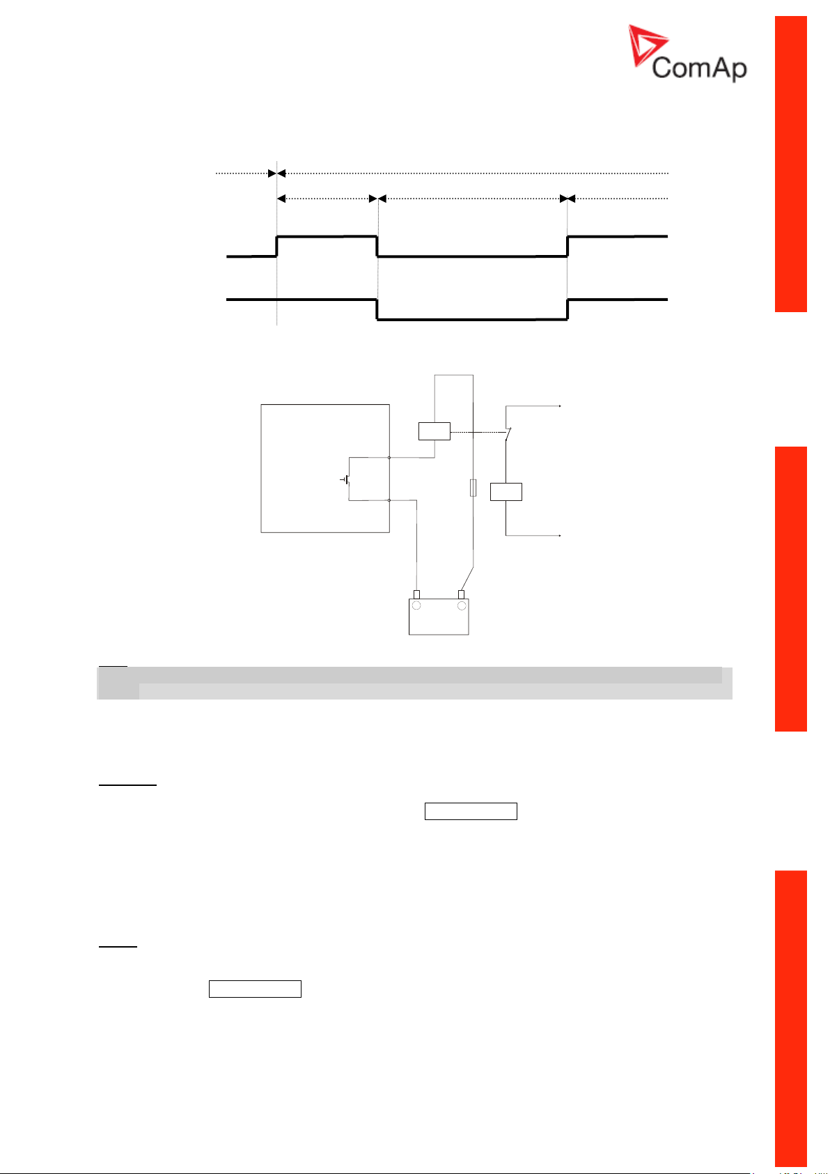
Mains O.K.
iL “OFF”
MCB logic = ”CLOSE-ON”
iL “ON”
Mains O.K.
Signal after external
inverted relay
MCB logic = ”CLOSE-OFF”
+
Battery
-
iL
DO 4
MCB
AUX.
INVERTING
RELAY
Hint:
In the case MCB Logic = “CLOSE-OFF” it is necessary to change externally the polarity of the output
signal.
ReturnFromTEST [MANUAL / AUTO]
The set point influences the behavior of the TEST mode.
MANUAL:
1) Select TEST, gen-sets starts and running unloaded
2) To transfer load from mains to the gen-set press MCB ON/OFF or wait for power-cut.
3) When mains recovers, the gen-set remains running loaded.
4) To stop the gen-set select AUTO Mode
5) In AUT Mode:
a) After the MainsReturnDel InteliLite opens the GCB
b) After the Transfer Del delay InteliLite closes the MCB.
c) The gen-set is cooled and stopped
AUTO:
1) Select TEST, gen-sets starts and running unloaded
2) To transfer load from mains to the gen-set wait for the power-cut. The controller does not
response for MCB ON/OFF button.
3) When the mains recovers:
a) After the MainsReturnDel the controller opens the GCB
b) After the Transfer Del delay the controller closes the MCB.
4) The gen-set remains running.
InteliLiteNT– AMF20/25, SW version 2.2, ©ComAp – September 2014 84
IL-NT-AMF-2.2-Reference Guide.pdf
Page 85

5) To stop the gen-set select a different mode than TEST.
Configuration
Protection
Under
Protection is activated only when measured value is under measured level.
Over
Protection is activated only when measured value is over measured level.
Under+fls
Level 2 protection is activated by Sensor Fail as well.
Over+fls
Level 2 protection is activated by Sensor Fail as well.
MCB Opens On [MAINSFAIL / GENRUN]
MAINSFAIL
The command to open the MCB is given immediately after mains fail condition is evaluated.
If the mains will return into parameters (MainsReturnDel passed) after MCB was opened and before
GCB is closed, timer MCBCloseDel is applied before MCB closing.
GENRUN
The command to open the MCB is not given till the Gen-set starts (with respecting the setpoint
EmergStart Del), reaches Running state, reaches proper voltage and frequency and Min Stab Time
elapses. After that, the MCB is opened, Transfer Del timer is started and the GCB is closed after the
timer elapses.
If the mains will return into parameters (MainsReturnDel passed) after MCB was opened and before
GCB was closed, again new timer TransferDel is applied before is MCB reclosed.
Hint:
This option should be used for MCBs using 230V control and not equipped with the undervoltage coil.
*Extension I/O
IOM AI1..4 Wrn [ ]
The warning level for IOM ANALOG INPUT 1..4 alarm detection.
Step: 1
Range: -100 – +10000
IOM AI1..4 Sd [ ]
The shutdown level for IOM ANALOG INPUT 1..4 alarm detection.
Step: 1
Range: -100 – +10000
IOM AI1..4 Del [s]
Delay for IOM ANALOG INPUT 1..4 alarm.
Step: 1 s
Range: 0 – 900 s
Hint:
IG-IOM/IGS-PTM analog inputs protection alarms can be configured following way
IOM AI1..4 Calibr […]
Calibrating constant to adjust the measured value of IOM/PTM analog inputs. Physical dimension of
calibrating constant is corresponding to Analog input.
Step: 1
Range: -1000 – +1000
Date/Time
Some of parameters in this group are only available at specific models of IL-NT.
*Time Stamp Per [min]
Time interval for periodic history records.
InteliLiteNT– AMF20/25, SW version 2.2, ©ComAp – September 2014 85
IL-NT-AMF-2.2-Reference Guide.pdf
Page 86

Step: 1 min
Range: 0 – 200min
Hint:
Time stamps are only recorded into history while gen-set is running. When is engine stopped there are
no time stamps records made.
*#SummerTimeMod [ DISABLED / WINTER / SUMMER, WINTER S, SUMMER-S ]
DISABLED: Automatic switching between summer and wintertime is disabled.
WINTER (SUMMER) : Automatic switching between summer and wintertime is enabled and it is set to
winter (summer) season.
WINTER-S (SUMMER-S) : Modification for southern hemisphere.
*#Time [HHMMSS]
Real time clock adjustment.
*#Date [DDMMYYYY]
Actual date adjustment.
Timer1..2Function [No Func / TEST / TEST OnLd / MFail Blk / Mode OFF]
It is possible to choose out of 5 following Timer functions. Binary output Exerc Timer X is always
activated when Timer is active regardless of chosen Timer function. Timer functions require controller
running in AUT mode.
Timer1 has higher priority over Timer2. So if Timer1 is configured for TEST mode
and Timer2 is over the same time configured for OFF mode, controller will work in TEST mode.
Controller activates timer whenever it is powered up even in period, where timer should be already
running.
No Func: There is no any other function, but binary output Timer1..2 activation.
TEST: When this option is chosen then the Timer output is also internally connected to the
Remote TEST binary input.
TEST OnLd: When this option is chosen then the Timer output is also internally connected to the
Rem TEST OnLd binary input.
MFail Blk: When this option is chosen then the Timer output is also internally connected to the
MainsFailBlock binary input.
Mode OFF: When this option is chosen then the Timer output is also internally connected to the
Remote OFF binary input.
*Timer 1..2 Repeat
[NONE/MONDAY/TUESDAY/WEDNESDAY/THURSDAY/WEDNESDAY/FRI
DAY/SATURDAY/SUNDAY/MON-FRI/MON-SAT/MON-SUN/SAT-SUN]
Defines TIMER 1,2 activation. Binary output TIMER 1,2 is internally linked with Rem Start/Stop binary
input. Refer to binary outputs „Exerc Timer X“ and particular binary inputs related to setpoint
Timer1..2Function for details.
NONE: Timer function is disabled
MONDAY, TUESDAY, WEDNESDAY, THURSDAY, WEDNESDAY, FRIDAY, SATURDAY, SUNDAY:
Timer is activated on daily basis.
MON-FRI, MON-SAT, SAT-SUN:
Timer is activated on selected day interval.
*Timer1..2 ON Time
Day time when Timer output activates.
InteliLiteNT– AMF20/25, SW version 2.2, ©ComAp – September 2014 86
IL-NT-AMF-2.2-Reference Guide.pdf
Page 87

*Timer1..2Duration
Terminal
Active alarm
sms
Active event
sms
Active alarm
email
Active event
email
IB-Lite
N/A
N/A
yes
yes
IB-NT
N/A
N/A
yes
yes*
IL-NT-GPRS
yes
yes
Not
supported
Not
supported
Duration of Timer output is active.
Step: 1 min
Range: 1 – 1440 s
Test Period [d]
After the given value of Test Period setpoint expires, the engine is started and is running as long as
the value of Test Duration setpoint. Test Period starts counting always when the engine is stopped.
Range: 0 – 240 days
^ Available only in AMF20.
Test Duration [min]
Time interval, when engine is running after expiring the Test Period setpoint.
Range: 0 – 240 minutes
^ Available only in AMF20.
Hint:
This function does not work till both setpoints (Test Period and Test Duration) are set to non-zero
values.
Sensors Spec
AI1, AI2, AI3 Calibration […]
Calibrating constant to adjust the measured value of IL analog inputs. Physical dimension
of calibrating constant is corresponding to Analog input.
Step: 1
Range: -1000 – +1000
Hint:
Calibration constants have to be adjusted when measured value is near the alarm level.
User curves can be defined by LiteEdit software.
SMS/E-Mail
Remote alarm messaging
If a GSM modem and/or Internet Bridge are connected to the controller, the controller can send SMS
messages and/or emails at the moment when a new alarm appears in the Alarmlist. The message will
contain a copy of the Alarmlist.
To enable this function, you should select with setpoints Yel Alarm Msg and Red Alarm Msg the levels
of alarms to be announced (red/yellow/both) and also enter a valid GSM phone number and/or e-mail
address to the setpoints TelNo/Addr Ch1 and TelNo/Addr Ch2. It is possible to set either a GSM
number or e-mail at both setpoints.
The list of all supported terminals shows the table below:
*since IB-NT 2.2.0
InteliLiteNT– AMF20/25, SW version 2.2, ©ComAp – September 2014 87
IL-NT-AMF-2.2-Reference Guide.pdf
Page 88

Controller is capable to detect which communication terminal is connected to the network and send
the email/SMS via the active one. InternetBridge-NT is preferred terminal if more possibilities are
detected.
NOTE:
An internet module must be available for sending e-mails and a GSM modem is necessary for sending
SMS. See the Communications chapter for more information.
Hint:
There are 5 attempts for any active call (SMS/E-Mail). Timeout for connection is 90 sec and after 120
sec controller starts the next attempt. During the time the IL-NT is trying to send an active call type,
incoming calls are blocked.
Yel Alarm Msg [ON/OFF]
Set this setpoint to ON if you want to get messages when a yellow (warning) alarm occurs.
Hint:
The target address (GSM phone number or e-mail address) must be set correctly to the setpoint(s)
TelNo/Addr Ch1 resp. TelNo/Addr Ch2.
Red Alarm Msg [ON/OFF]
Set this setpoint to ON if you want to get messages when a red (shutdown or BOC) alarm occurs.
Hint:
The target address (GSM phone number or e-mail address) must be set correctly to the setpoint(s)
TelNo/Addr Ch1 resp. TelNo/Addr Ch2.
Event Msg [ON/OFF]
Set this setpoint to ON if you want to get messages when a new event occurs.
Hint:
The target address (GSM phone number or e-mail address) must be set correctly to the setpoint(s)
TelNo/Addr Ch1 resp. TelNo/Addr Ch2.
TelNo/Addr Ch1, 2
Enter either a valid GSM phone number or e-mail address to this setpoint, where the alarm messages
shall be sent. Type of active call is considered from the value of this parameter. If it consist „@“ it is
supposed to be e-mail address and active e-mail is sent. If the value is number, without „@“, it is
supposed to be the telephone number and active SMS is sent.
Hint:
For GSM numbers use either national format (i.e. like number you will dial if you want to make a local
call) or full international format with "+" character followed by international prefix in the begin.
Phone numbers and emails can be modified from controller display or from PC.
Following buttons are used for phone number modification
- ENTER for - opening the modification
- confirmation of particular number change and jump to the next position
- confirmation of the last number and closing of the modification
- MODE for - while adjusting character press Mode button to jump between character groups to
fasten the process.
- and for - particular number/character change
Particular numbers/character can take values: from “0” to “9”, “a” to “z”, various symbols and empty
space.
InteliLiteNT– AMF20/25, SW version 2.2, ©ComAp – September 2014 88
IL-NT-AMF-2.2-Reference Guide.pdf
Page 89

SMS Language [1/2]
Select 1 to receive a message in primary controller language or 2 for secondary one.
Alternate Cfg
Based on the value on BI Alt. Config is selected controller configuration 1 or configuration 2 (all related
setpoints are placed in Alternate Cfg group).
Hint:
Controller will react on change of binary input only while engine is stopped. On successful change of
input the new record in history ("Nominal1Active", "Nominal2Active") is added.
Hint:
If the configuration 1 will contain setting for 50Hz and configuration 2 for 60Hz it is possible to use this
feature for 50/60 Hz switch.
Nominal RPM 1..2 [RPM]
Nominal engine speed.
Step: 1RPM
Range: 100 – 4000 RPM
Nominal Freq 1..2 [Hz]
Nominal generator frequency (usually 50 or 60 Hz )
Step: 1Hz
Range: 45 – 65 Hz
NomVolts Ph-N 1..2 [V]
Nominal generator voltage (phase to neutral)
Step: 1V
Range: 80 – 20000 V
Hint:
Phase sequence check is not possible to evaluate under voltage 50V what causes that if measured
voltage 50V is within the allowed range, controller will not allow to close the GCB, even if relevant LED
diode on front panel of IL-NT lits.
NomVolts Ph-Ph1..2 [V]
Nominal generator voltage (phase to phase)
Step: 1V
Range: 138 – 35000 V
Nomin Current 1..2 [A]
It is current limit for generator *IDMT over current and short current protection and means maximal
continuous generator current. See Gener Protect: *Amps IDMT Del, Short Crct Sd setpoints.
Nominal Current can be different from generator rated current value.
Step: 1 A
Range: 1 - 10000 A
ConnectionType 1..2 [3Ph4Wire / 3Ph3Wire / Split Ph / Mono Ph]
Generator winding connection.
3Ph4Wire: STAR Connection, 3 phases and neutral - 4 wires,
Three phase “wye” measurement – 3PY, 3x CT‘s
3Ph3Wire: DELTA Connection, 3 Phase without neutral - 3 Wires,
Three phase “delta” measurement – 3PD, 3x CT‘s
Split Phase: DOUBLE DELTA Connection, Split Phase,
Single-phase measurement – 1PH, 1xCT
Mono Phase: MONOPHASE,
InteliLiteNT– AMF20/25, SW version 2.2, ©ComAp – September 2014 89
IL-NT-AMF-2.2-Reference Guide.pdf
Page 90

Single-phase measurement – 1PH, 1x CT
Hint:
For more details about connection types see Voltage measurement and generator connection types
chapter.
For details about influence of Connection type setting on voltage values in history check History file
chapter.
ECU FreqSelect1..2 [PRIMARY/SECONDARY/DEFAULT]
This setpoint should be used only for Volvo and Scania engines.
Volvo – “Volvo Aux” is selected in ECU configuration:
Primary or secondary engine speed is set by Frequency select bits in VP Status frame.
Scania – “Scania S6 Singlespeed” is selected in ECU configuration:
Nominal engine speed is chosen by Nominal speed switch 1 and 2 from DLN1 frame when the engine
is running on nominal speed, i.e. binary output Idle/Nominal is active. When the output is not active
(engine is running on Idle speed), the setpoint ECU FreqSelect is not taken into account.
Frequency change for Volvo Penta engines with EMS2
This description refers to the Volvo Penta Application bulletin 30-0-003.
The procedure for changing engine speed on the D9 and D16 engines is different from the D12
engine.
There is no system reset on the EMS2 unit; therefore the procedure is changed.
Procedure if ECU not energized:
5. Switch the IL controller to MAN Mode.
6. Power up the ECU.
7. Change the setpoint ECU FreqSelect and confirm it by pressing Enter
8. Press the Stop button on the IL controller.
The whole procedure (step 2 to 4) must not exceed 10 seconds.
Procedure with ECU powered on:
5. Switch the IL controller to MAN Mode.
6. Press the Stop button on the IL controller.
7. Change the setpoint ECU FreqSelect and confirm it by pressing Enter
8. Press the Stop button on the IL controller.
The whole procedure (step 2 to 4) must not exceed 10 seconds.
ECU SpeedAdj 1..2 [ % ]
Enables to adjust engine speed in ECU via CAN bus. Nominal speed corresponds to 50%.
Step: 1%
Range: 0 – 100%
Hint:
The minimum value 0% is equal to 90% of nominal speed. Maximum value 100% is equal to 110% of
nominal speed.
*EarthFaultProt
Hint:
More information is available in Earth fault Measurement chapter.
EF Protection [ENABLED/DISABLED]
This setpoint can block or allow Earth fault Current protection.
InteliLiteNT– AMF20/25, SW version 2.2, ©ComAp – September 2014 90
IL-NT-AMF-2.2-Reference Guide.pdf
Page 91

EF CT Ratio [/5A]
Earth Fault current transformer ratio.
Step: 1 A
Range: 1 – 2000 A /5A
EarthFault Sd [A]
Shutdown threshold level for Earth Fault current.
Step: 0,01 A
Range: 1 – 500 A
EarthFault Del [s]
Earth Fault current measurement delay.
Step: 0,01s
Range: 1 – 5s
InteliLiteNT– AMF20/25, SW version 2.2, ©ComAp – September 2014 91
IL-NT-AMF-2.2-Reference Guide.pdf
Page 92

*ECU-controlled engine support
There exists only one firmware branch for both standard and electronic controlled (monitored)
engines.
Presence of the ECU on the CAN bus/RS232 is configured via LiteEdit like other peripheries (IG-IOM,
IGL-RA15). Pressing the button in Configuration window of LiteEdit opens ECU dialog window
where the appropriate engine/ECU type should be selected. The actual list of ECU types is available
on ComAp website in "ECU list - x.y.iwe" package. Download this package and import it into LiteEdit in
the same way as standard firmware IWE package.
More information about ECU list packages, configuration and wiring recommendations can be found in
ComAp Electronic Engines Support manual.
If the connected engine is Cummins with GCS engine control unit communicating via Modbus it is
necessary to set the setpoint Basic settings: COM1 Mode = ECU LINK or COM2 Mode = ECU LINK.
Loss of communication causes a warning alarm. On the contrary the ECU can be switched off at
quiescent engine that means not-communicating ECU is in that moment normal situation. All values
from ECU shall show ####, but no alarm is displayed. The output ECU Comm OK follows the real
situation which means it is not active anytime when the ECU does not communicate.
The output ECU PowerRelay closes at the beginning of prestart and opens if the engine shall be
stopped. It can be used to switch the ECU on and off. If the output is configured but not active the
ECU communication alarm is blocked.
InteliLiteNT– AMF20/25, SW version 2.2, ©ComAp – September 2014 92
IL-NT-AMF-2.2-Reference Guide.pdf
Page 93

The engine is started via standard contact output or via CAN bus depending on ECU capabilities.
Motor ID
ESF - Electronic Engine
1
Volvo EMSI Singlespeed / EMSII
3
Scania S6 Singlespeed
4
Cummins CM570
5
Cummins MODBUS
7
John Deere
8
Deutz EMR2
9
DDC DDEC IV/V
10
Caterpillar J1939
12
Perkins ECM
14
Iveco NEF&Cursor
16
Scania S6 Singlespeed from
ver.1794335
18
SISU EEM3 Gen-set
20
MTU ADEC J1939
23
JCB Delphi DCM
24
Daimler Chrysler ADM2
25
Deutz EMR3
26
Cummins CM850
28
Iveco Vector
29
MAN MFR
31
VM Marine
32
VM Industrial
35
GM SECM
36
ISUZU ECM
43
Cummins CM850/CM2150/CM2250
44
GM e-control ECU
58
GM e-control LCI
60
MTU SMART Connect
68
Scania S8 Singlespeed
71
GM MEFI6
255
Standard J1939 engine
Identifying configured ECU
It is possible to identify what ECU is currently configured in IL-NT (FW version ≥1.5) controller on init
screens. Navigate to default screen with gauge and press buttons PAGE and ENTER at the same
time. Than browse through inits screen by button PAGE until you find value "ESF:xx.y - (zzz)", where
xx.y = ESF version number, zzz= Motor ID.
Explanation of Motor ID is in table below:
Values read from ECU
There is fixed set of values read from J1939 ECU by IL-NT controller:
Engine speed (frame EEC1)
Engine oil pressure (frame Engine Fluid Level/Pressure)
Engine coolant temperature (frame Engine Temperature)
Total engine hours (frame Engine Hours, Revolutions)
Fuel rate (frame Fuel Economy)
Boost pressure (frame Inlet/Exhaust Conditions)
Intake manifold 1 temperature (frame Inlet/Exhaust Conditions)
Engine oil temperature 1 (frame Engine Temperature 1)
InteliLiteNT– AMF20/25, SW version 2.2, ©ComAp – September 2014 93
IL-NT-AMF-2.2-Reference Guide.pdf
Page 94

When “ECU LINK”-Modbus option is selected, following values are read from Modbus Register Data
(for QSX15,QSK45, QSK60):
Engine Speed (Register Address:30001)
Oil Pressure (Register Address:30003)
Coolant Temperature (Register Address:30002)
Engine Running Time (Register Address:30008-30009)
Fuel Consumption Rate (Register Address:30018)
Intake Manifold Absolute Pressure (Register Address:30530 (QSK45, QSK60 only))
Intake Manifold Temperature (Register Address:30531 (QSK45, QSK60 only))
Hint:
Values read from ECU are not written to history besides the fault codes.
Diagnostic messages read from ECU
Diagnostic messages are read and displayed in extra ECU Alarm list. For Standard J1939 SPN
(Suspect Parameter Number), FMI (Failure Mode Identifier) and OC (Occurrence Counter) are shown
together with text description if available.
One SPN (Suspect Parameter Number) / FMI (Failure Mode Identify) couple describes one fail
information. If FMI is equal to 0 or 1, WRN is displayed in the ECU Alarm list. For any other FMI
values, FLS is displayed.
Detail SPN/FMI code specification see in:
SAE Truck and Bus Control and Communications Network Standards Manual, SAE HS-1939
Publication
Or refer to corresponding engine manufacturer’s ECU error codes list.
Complete list of text diagnostic messages for each ECU can be found in ComAp Electronic Engines
Support manual.
Hint:
InteliLite controller doesn’t support J1587 diagnostic line on Volvo engines. This can cause in some
cases a J1939 alarm message FC:000608 due to missing J1587 bus. Contact your Volvo distributor to
update ECU firmware.
For Scania engines the fault codes are displayed in hexadecimal format.
Analog inputs
Reading of mentioned values from ECU enables to use analog inputs of the unit for other purposes,
e.g. measuring, displaying and alarm activation related to various quantities. The configuration thus
allows to use three analog inputs on the central unit and four analog inputs on IG-IOM/IGS-PTM
module if connected.
InteliLiteNT– AMF20/25, SW version 2.2, ©ComAp – September 2014 94
IL-NT-AMF-2.2-Reference Guide.pdf
Page 95

Connection description
The following diagrams show how to connect the engine control unit to the InteliLite controller:
Engines with J1939 support started via CAN bus
VOLVO PENTA engines (EMS II, EDC III units)
InteliLiteNT– AMF20/25, SW version 2.2, ©ComAp – September 2014 95
IL-NT-AMF-2.2-Reference Guide.pdf
Page 96

SCANIA S6
LOAD
ACCESS LOC K
EMERGENCY STO
P
CONTROL
SIGNALS
GEN C.B. FEED-BACK
MAINS C.B. FEED
-BA
CK
DIESEL/GAS ENGINE
RPM
GENERATOR
G
+24V
L1
L2
L3
N
Generator C.B.
Mains C.B.
SPRINKLER
REMOTE TEST
RS-232C
Interface
Modemor PC
REMOTE OFF
ALARM
BINARY OUTPUTS
MAINS C.B
.
GENC.B
.
PRESTART
READY TO L OAD
FUEL LEVEL
ECU
10
-pin EMS B1
connector
3
4 5 6 7 8
9 10
21
+24 V DC
GND
InteliLiteNT– AMF20/25, SW version 2.2, ©ComAp – September 2014 96
IL-NT-AMF-2.2-Reference Guide.pdf
Page 97

Cummins engines with MODBUS communication
LOAD
ACCESS LOC K
EMERGENCY STO
P
CONTRO
L
SIGNALS
GEN C.B. FEED-BACK
MAINS C.B. FEED
-BA
CK
DIESEL/GAS ENGINE
RPM
GENERATOR
G
+24V
L1
L2
L3
N
Generator C.B.
Mains C.B.
SPRINKLER
REMOTE TEST
REMOTE OFF
ALARM
BINARY OUTPUTS
MAINS C.B
.
GENC.B
.
PRESTART
READY TO L OAD
STARTER
BATTERY
-
+
FUELSOLENOI
D
D+
FUELSOLENOI
D
STARTER
ECU
10-30
VDC
GND
RxD
TxD
ADAM 4520 RS232/485
CONVERTER
DATA1+
DATA1-
RS232
RS485
D-SUB 06
CONNECTOR
RS485 - ( PIN 18)
GND (PIN 20)
RS485 + (PIN 21)
TERM2 (PIN 19)
TERM1 (PIN 22)
GND
+Vs
InteliLite set up:
Basic settings:COM1 Mode = ECU LINK or COM2 Mode = ECU LINK
Software configuration: ECU → ECU engine is connected → Type: Cummins MODBUS
RS232/RS485 converter (see following diagram) set up:
Data format settings (SW1) 11 bits (1 start bit, 8 data bits, 2 stop bits)
Baud rate settings (SW2) 9600 bps
(more info available on http://www.advantech.com/products/Model_Detail.asp?model_id=1-D6FLH)
InteliLiteNT– AMF20/25, SW version 2.2, ©ComAp – September 2014 97
IL-NT-AMF-2.2-Reference Guide.pdf
Page 98

Sensor Specification
Curve
Min Value
Max Value
Unit
Datcon 5 Bar
0 5 Bar
Datcon 7 Bar
0 7 Bar
Datcon 10 Bar
0
10
Bar
Datcon 80 Psi
0
80
Psi
Datcon 100 Psi
0
100
Psi
Datcon 150 Psi
0
150
Psi
Datcon Low °C
25
150
°C
Datcon High °C
25
160
°C
Datcon Low °F
80
300
°F
Datcon High °F
80
320
°F
Datcon Fuel %
0
100
%
VDO 5 Bar
0
5
Bar
VDO 10 Bar
0
10
Bar
VDO 72 Psi
0
72
Psi
VDO 145 Psi
0
145
Psi
VDO 40-120 °C
40
120
°C
VDO 50-150 °C
50
150
°C
VDO 100-250 °F
100
250
°F
VDO 120-300°F
120
300
°F
VDO Fuel %
0
100
%
Background of the sensor calibration
To correct measuring error of each analog input (pressure, temperature, level) calibrating constants
within 10 % of measure range should be set. Two calibrating constants are set in physical units - bar,
o
C, % .Calibration is made by adding the value of setpoint AIxCalibration directly to the calculated
value at analog input.
Hint:
The calibration must be done at the operational point of the analog input (e.g. 80°C, 4.0Bar etc..)
Default sensor curves
There are 20 default resistive curves available. The following table provides information on
minimum/maximum values of respective sensors. Actual values especially of temperature curves may
differ. Meaning is to prolong curve to the lower temperature values, so the cold engine will not raise
alarm fail sensor.
Hint:
You can find detail information on sensors in LiteEdit Reference Guide and details about sensor fails
in this manual in chapter Alarm Management - Sensor Fail (FLS).
InteliLiteNT– AMF20/25, SW version 2.2, ©ComAp – September 2014 98
IL-NT-AMF-2.2-Reference Guide.pdf
Page 99

Function Description
State
Condition of the transition
Action
Next state
Ready
Start request
PRESTART on
Prestart Time counter
started
Prestart
RPM > 2 or Oil pressure > Starting OilP
detected or Gen voltage > 10V
Stop (Stop fail)
OFF Mode selected or Shut down alarm
active
Not Ready
Not Ready
RPM < 2, Oil pressure not detected, Vgen
< 10V, D+ not Active no shutdown alarm
active, other than OFF Mode selected
Ready
Prestart
3
Prestart time elapsed
STARTER on
FUEL SOLENOID on
4
MaxCrank Time counter
started
Cranking
OFF Mode
No start of the gen-set is possible. Outputs STARTER, GCB CLOSE/OPEN and FUEL SOLENOID are
not energized.
No reaction if buttons START,STOP,GCB ON/OFF, MCB ON/OFF are pressed.
When power-cut comes, MCB CLOSE/OPEN opens. After mains returns, MCB CLOSE/OPEN closes
with MCB close del.
MAN Mode
START. - starts the gen-set.
GCB ON/OFF
The controller closes GCB to dead bus.
The controller opens GCB when closed.
If the generator voltage is out of the limits, the controller does not to respond to the GCB
ON/OFF
MCB ON/OFF
The controller closes MCB to dead bus.
The controller opens MCB when closed.
STOP stops the gen-set.
Hint:
The engine can run without load unlimited time.
The controller does not automatically stop the running gen-set in MAN Mode.
The controller does not start the gen-set when power cut comes.
!! The controller provides interlock between GCB and MCB, it means it is never possible to
close both CB together
Start-stop sequence (simplified)
MODE = MAN (Engine start/stop request is given by pressing buttons START and STOP )
MODE = AUT (Engine start/stop request is evaluated form Mains failure/return)
InteliLiteNT– AMF20/25, SW version 2.2, ©ComAp – September 2014 99
IL-NT-AMF-2.2-Reference Guide.pdf
Page 100

State
Condition of the transition
Action
Next state
Cranking 3
RPM> Starting RPM
STARTER off
PRESTART off
Starting
D+ input activated or oil pressure detected
or Gen voltage > 25% Vgnom
STARTER off
PRESTART off
Starting
MaxCrank Time elapsed, 1st attempt
STARTER off
FUEL SOLENOID off
STOP SOLENOID on
CrankFail Pause timer
started
Crank pause
MaxCrank Time elapsed, last attempt
STARTER off
PRESTART off
Shutdown (Start
fail)
Crank
pause 3
CrankFail Pause elapsed
STARTER on
FUEL SOLENOID on
4
STOP SOLENOID off
MaxCrank Time counter
started
Cranking
Starting 3
80% Nominal RPM reached
READY TO LOAD on
1
Min, Max Stab Time
counter started
Running
RPM = 0 or any other shutdown condition
FUEL SOLENOID off
STOP SOLENOID on
Shutdown
60 sec. Elapsed
FUEL SOLENOID off
STOP SOLENOID on
Shutdown (Start
fail)
Running
Stop request
READY TO LOAD off
Cooling Time timer
started
Cooling
RPM = 0 or any other shutdown condition
READY TO LOAD off
2
FUEL SOLENOID off
Shutdown
GCB CLOSE/OPEN closed
Loaded
Loaded
GCB CLOSE/OPEN opened
Running
RPM = 0 or any other shutdown condition
FUEL SOLENOID off
STOP SOLENOID on
READY TO LOAD off
Shutdown
Cooling
Cooling Time elapsed
FUEL SOLENOID off
STOP SOLENOID on
Stop
RPM = 0 or any other shutdown condition
FUEL SOLENOID off
STOP SOLENOID on
Shutdown
Start request
READY TO LOAD on
1
Running
Stop
RPM = 0, Oil pressure not detected, Vgen <
10V, D+ not active
Ready
If at least one of engine running indication is
detected when Setpoint Stop Time elapsed.
See more details in chapter Gen-Set
Operation state – Stop engine conditions
Stop (Stop fail)
1
if all generator parameters OK and Min Stab Time elapsed, indicates that GCB is possible to close.
In AUTO Mode closes in this moment GCB automatically.
2
If GCB output used GCB opens automatically
3
The start-up sequence can be interrupted in any time by coming stop request
4
Fuel solenoid is switched on with time advance of 1s fixed before starter motor is switched on.
Hint:
InteliLiteNT– AMF20/25, SW version 2.2, ©ComAp – September 2014 100
IL-NT-AMF-2.2-Reference Guide.pdf
 Loading...