

Page 1

InteliLite 9
Controller for single gen-set
SW version 1.1.0
1 Document information 6
2 System overview 11
3 Applications overview 16
applications
4 Installation and wiring 18
5 Controller setup 45
6 Communication 111
7 Technical data 137
8 Appendix 139
Copyright © 2018 ComAp a.s.
Written by MichalSlavata, Daniel Švanda
Prague, Czech Republic
ComAp a.s., U Uranie 1612/14a,
170 00 Prague 7, Czech Republic
Tel: +420 246 012 111
E-mail: info@comap-control.com, www.comap-control.com
Global Guide
Page 2

Table of contents
1 Document information 6
1.1 Clarification of notation 6
1.2 About this Global Guide 6
1.3 Legal notice 6
1.4 General warnings 8
1.4.1 Remote control and programing 8
1.4.2 SW andHW versions compatibility 8
1.4.3 Dangerous voltage 8
1.4.4 Adjust thesetpoints 8
1.5 Certifications and standards 9
1.6 Document history 9
1.7 Symbols in this manual 10
2 System overview 11
2.1 General description 11
2.1.1 The key features of InteliLite 9 11
2.2 TrueRMS measurement 11
2.3 Configurability and monitoring 11
2.3.1 Supported configuration and monitoring tools 12
2.3.2 Configurationparts 12
2.4 PC Tools 13
2.4.1 InteliConfig 13
2.4.2 WinScope 13
2.5 Plug-in Modules 14
2.5.1 CM-Ethernet 14
2.5.2 CM-4G-GPS 14
2.5.3 CM-GPRS 15
2.5.4 CM-RS232-485 15
2.5.5 EM-BIO8-EFCP 15
3 Applications overview 16
3.1 AMF - Automatic Mains Failure Start 16
3.2 MRS - Manual Remote Start 16
4 Installation and wiring 18
4.1 Package content 18
4.2 Controller installation 18
4.2.1 Dimensions 18
InteliLite9 Global Guide
2
Page 3

4.2.2 Mounting 19
4.3 Terminal Diagram 20
4.4 Recommendedwiring 21
4.4.1 General 22
4.4.2 Grounding 22
4.4.3 Power supply 22
4.4.4 Measurement wiring 23
4.4.5 Magnetic pick-up 30
4.4.6 Binary inputs 32
4.4.7 Binary Outputs 33
4.4.8 E-Stop 34
4.4.9 Analog inputs 34
4.4.10 CAN bus 38
4.4.11 USB 40
4.4.12 Example of AMF Wiring 41
4.4.13 Example of MRS Wiring 42
4.5 Plug-in module installation 43
4.5.1 Installation 43
5 Controller setup 45
5.1 Default configuration 45
5.1.1 Binary inputs AMF 45
5.1.2 Binary outputs AMF 45
5.1.3 Binary inputs MRS 45
5.1.4 Binary outputs MRS 46
5.1.5 Analog inputs 46
5.2 Controller configuration and PC tools connection 46
5.2.1 USB 46
5.2.2 RS232/RS485 47
5.2.3 Ethernet 49
5.3 Operator Guide 50
5.3.1 Front panel elements 51
5.3.2 Display screens and pages structure 52
5.3.3 Browsing alarms 65
5.3.4 Password 66
5.3.5 Information screen 72
5.3.6 Language selection 73
5.3.7 Display contrast adjustment 74
5.4 Functions 74
5.4.1 Start-stop sequence 75
InteliLite9 Global Guide
3
Page 4

5.4.2 AMF sequence 77
5.4.3 Operating Modes 78
5.4.4 Engine start 79
5.4.5 Stabilization 81
5.4.6 Connecting to load 81
5.4.7 MRS operation 81
5.4.8 AMF operation 81
5.4.9 Engine cool down and stop 82
5.4.10 Alarm management 83
5.4.11 History log 89
5.4.12 Breaker control 90
5.4.13 Exercise timer 93
5.4.14 Service timers 99
5.4.15 Flowchart 101
5.4.16 Additional running engineindications 102
5.4.17 Voltage phase sequence detection 102
5.4.18 Gen-set operation states 102
5.4.19 Sensor curves 105
5.4.20 Tier 4 Final 105
5.4.21 Alternate configuration 108
5.4.22 E-Stop 109
5.4.23 ECU Frequency selection 110
6 Communication 111
6.1 PC 111
6.1.1 Direct communication 111
6.1.2 Remote communication 113
6.2 Connection to 3rd party systems 124
6.2.1 MODBUS-RTU, MODBUS/TCP 124
7 Technical data 137
8 Appendix 139
8.1 Controller objects 140
8.1.1 Setpoints 141
8.1.2 Values 258
8.1.3 Logical binary inputs 293
8.1.4 Logical binary outputs 314
8.1.5 Logical analog inputs 348
8.2 Alarms 356
InteliLite9 Global Guide
4
Page 5

8.2.1 Alarms level 1 356
8.2.2 Alarms level 2 372
8.2.3 Fail sensor and othertypes 385
8.3 Modules 388
8.3.1 Plug-In modules 389
InteliLite9 Global Guide
5
Page 6

1 Document information
1.1 Clarification of notation 6
1.2 About this Global Guide 6
1.3 Legal notice 6
1.4 General warnings 8
1.5 Certifications and standards 9
1.6 Document history 9
1.7 Symbols in this manual 10
6 back to Table of contents
1.1 Clarification of notation
Note: This type of paragraph calls readers attention to a notice or related theme.
IMPORTANT: This type of paragraph highlights a procedure, adjustment etc., which can cause a
damage or unproper function of the equipment if not performed correctly and may not be clear at
first sight.
Example: This type of paragraph contains information that is used to illustrate how a specific function
works.
1.2 About this Global Guide
This manual contains important instructions forInteliLite 9 controllers family that shall be followed during
installation and maintenance of the controllers.
This manual provides general information how to install and operate InteliLite 9 controllers.
This manual is dedicated for:
Operators of gen-sets
Gen-set control panel builders
For everybody who is concerned with installation, operation and maintenance of the gen-set
1.3 Legal notice
This End User's Guide/Manual as part of the Documentationis an inseparable part of ComAp’s Product and
may be used exclusively according to the conditions defined in the “END USER or Distributor LICENSE
AGREEMENT CONDITIONS – COMAP CONTROL SYSTEMS SOFTWARE” (License Agreement) and/or in
the “ComAp a.s. Global terms and conditions forsale of Products and provision of Services” (Terms) and/or in
the “Standardní podmínky projektů komplexního řešení ke smlouvě o dílo, Standard Conditions for Supply of
Complete Solutions” (Conditions) as applicable.
ComAp’s License Agreement is governed by the Czech Civil Code 89/2012 Col., by theAuthorship Act
121/2000 Col., by international treaties and by other relevant legal documents regulating protection of the
intellectual properties (TRIPS).
InteliLite9 Global Guide
6
Page 7

The End User and/orComAp’s Distributor shall only be permitted to use this End User's Guide/Manual with
ComAp Control System RegisteredProducts. The Documentation is not intended and applicable for any other
purpose.
Official versionof the ComAp’s End User's Guide/Manual is the version publishedin English. ComAp reserves
the right to update this End User's Guide/Manual at any time. ComAp does not assume any responsibility for its
use outside of the scope of the Terms or the Conditions and the License Agreement.
Licensed End User is entitled to make only necessary number of copies of the End User's Guide/Manual. Any
translation of this End User's Guide/Manual without the priorwritten consent of ComAp is expressly prohibited!
Even if the prior written consent from ComAp is acquired, ComAp does not take any responsibility for the
content, trustworthiness and quality of any such translation. ComAp will deem a translationequal to this End
User's Guide/Manual only if it agrees to verify such translation. The terms and conditions of such verification
must be agreed in the written form and in advance.
For more details relating to the Ownership, Extent of Permitted Reproductions Term of Use of the
Documentation and to the Confidentiality rules please review and comply with the ComAp’s License
Agreement, Terms and Conditions available on www.comap-control.com.
Security Risk Disclaimer
Pay attention to thefollowing recommendations and measures to increase the level of security of ComAp
products and services.
Please note that possible cyber-attacks cannot be fully avoided by the below mentioned recommendations and
set of measures already performed by ComAp, but by following them the cyber-attacks can be considerably
reducedand thereby to reduce the risk of damage. ComAp does not take any responsibility for the actions of
persons responsible for cyber-attacks, nor for any damage caused by the cyber-attack. However, ComAp is
prepared to provide technical support to resolve problems arising from such actions, including but not limited to
restoring settings prior to thecyber-attacks, backing up data, recommending other preventive measures against
any further attacks.
Warning: Some forms of technical support may be provided against payment. Thereis no legal or factual
entitlement for technical services provided in connection to resolving problems arising from cyber-attack or
other unauthorized accesses to ComAp's Products or Services.
General security recommendations and set of measures
1. AccessCode
• Change the AccessCode BEFORE the device is connected to a network.
• Use a secure AccessCode – ideally a random string of 8 characters containing lowercase, uppercase letters
anddigits.
• Foreach device use a different AccessCode.
2. Password
• Change the password BEFORE the device enters a regular operation.
• Do not leave displays or PC tools unattended if an user, especially administrator, is logged in.
3. Controller Web interface
• Thecontroller web interface at port TCP/80 is based on http, not https, and thus it is intended to be used only
in closed private network infrastructures.
• Avoid exposing the port TCP/80 to thepublic Internet.
4. MODBUS/TCP
• TheMODBUS/TCP protocol (port TCP/502)is an instrumentation protocol designed to exchange data
between locally connected devices like sensors, I/O modules, controllers etc. From it’s nature it does not
InteliLite9 Global Guide
7
Page 8

contain any kind of security – neither encryption nor authentication. Thus it is intended to be used only in closed
private network infrastructures.
• Avoid exposing the port TCP/502 to thepublic Internet.
5. SNMP
• TheSNMP protocol (port UDP/161)version 1,2 is not encrypted. Thus it is intended to be used only in closed
private network infrastructures.
• Avoid exposing the port UDP/161 to the public Internet.
Used Open Source Software: mBed-TLS
https://www.mbed.com/en/development/software/mbed-tls/
http://www.apache.org/licenses/LICENSE-2.0
1.4 General warnings
1.4.1 Remote control and programing
Controller can be remotely controlled. In the event that maintenance of gen-set has to be done, or controller has
to be programmed, check the following points to ensure that theengine cannot be started or any other parts of
the system cannot be effected.
To be sure:
Disconnect remote control
Disconnected binary outputs
1.4.2 SW and HW versions compatibility
Be aware to use proper combination of SW and HW versions.
1.4.3 Dangerous voltage
In no case touch the terminals forvoltage andcurrent measurement!
Always connect grounding terminals!
In any case do not disconnect controller CT terminals!
1.4.4 Adjust the setpoints
All parameters are adjusted to theirtypical values. Howeverthe setpoints has to be checked andadjusted to
their real values before the first starting of the gen-set.
IMPORTANT: Wrong adjustment of setpoints can destroy the gen-set.
Note: The controller contains a large number of configurable setpoints, because of this it is impossible to
describe all of its functions. Some functions can be changed or have different behavior in different SW versions.
Always check the Global guide and New feature list for SW version which is used in controller. This manual
only describes the product and is not guaranteed to be set for your application.
IMPORTANT: Be aware that the binary outputs can change state during and after software
reprogramming (before the controller is used again ensure that the proper configuration and
setpoint settings are set in the controller).
InteliLite9 Global Guide
8
Page 9

The following instructions are for qualified personnel only. To avoid personal injury do not perform any action not
specified in related guides for product.
1.5 Certifications and standards
EN 61000-6-2
EN 61000-6-4
EN 61010-1
EN 60068-2-1 (-20 °C/16 h for std, -40 °C/16 h for LT version)
EN 60068-2-2 (70 °C/16 h)
EN 60068-2-6 (2÷25 Hz / ±1,6 mm; 25÷100 Hz / 4,0 g)
EN 60068-2-27 (a=500 m/s2; T=6 ms)
EN 60068-2-30:2005 25/55°C, RH 95%, 48hours
EN 60529 (front panel IP65, back side IP20)
1.6 Document history
Revision number Related sw. version Date Author
2 1.1.0 12.9.2018 Michal Slavata
1 1.0.0 2.11.2017 Daniel Švanda
InteliLite9 Global Guide
9
Page 10

1.7 Symbols in this manual
3 x Phases
Active
current
sensor
AirGate
Alternating
current
Analog
modem
Battery
Binary
output
Breaker
contact
Breaker
contact
Breaker
Breaker
Breaker
Connector -
male
Contact
Contactor
Controller
simplified
Module
simplified
Current
measuring
Current
measuring
Diode
Ethernet
male
Ethernet
female
Fuel
solenoid
Fuse
Grounding
GSM
GSM
modem
IG-AVRi
IG-AVRi
TRANS
Jumper
Load
Mains
Mains
Mobile
provider
Passive
current
sensor
Pick - up
Resistor
adjustable
Resistive
sensor
RPTC
RS232
male
RS232
female
Starter
Switch -
manually
operated
Transformer
USB type B
male
USBtype B
female
Voltage
measuring
Wifi / WAN /
LAN
6 back to Document
information
Capacitor
Coil
Connector -
female
InteliLite9 Global Guide
Fuse switch
Generator
Generator
schematic
Relay coil
Relay coil of
slow-
operating
Resistor
10
Page 11

2 System overview
2.1 General description 11
2.2 TrueRMS measurement 11
2.3 Configurability and monitoring 11
2.4 PC Tools 13
2.5 Plug-in Modules 14
6 back to Table of contents
2.1 General description
InteliLite 9 Family controllers are comprehensive gen-set controllers for single gen-sets operating in stand-by
(MRS) or back-up (AMF) applications. A modular construction allows upgrades to different levels of complexity
in order to provide the best solution for various customer applications. The controllers are equipped with a
powerful graphic display showing icons, symbols and bar graphs for intuitive operation, which, together with its
highlevel of functionality, sets new standards in Gen-set controls.
2.1.1 The key features of InteliLite 9
Easy-to-use operation and installation. The factory default configuration covers most applications
Various customizations are possible thanks to its configurability
Excellent remote communication capabilities
High level of support for EFI engines (most world producers)
High reliability
2.2 True RMS measurement
This controller measures AC values based on True RMS principle. This principle corresponds exactly to the
physical definition of alternatingvoltage effective values. Undernormal circumstances themains voltage
should have a pure sinusoidal waveform. However some nonlinearelements connected to the mains produce
harmonic waveforms with frequencies of multiplies of the basic mains frequency and this may result in
deformation of the voltage waveforms. The True RMS measurement gives accurate readings of effective values
not only for puresinusoidal waveforms, but also fordeformed waveforms.
Note: The harmonic deformation causes that the Power Factor of a generator working parallel with the mains
cannot reach values in a certain range around the PF 1.00. The higher the deformation, the wider the power
factor dead range. If the requested power factor is adjusted inside the dead range, the controller cannot reach
the requested value because of this fact.
2.3 Configurability and monitoring
Oneof the key features of the controller is the system’s high level of adaptability to the needs of each individual
application and wide possibilities for monitoring. This can be achieved by configuring and using thepowerful
PC/mobile tools.
InteliLite9 Global Guide
11
Page 12
2.3.1 Supported configuration and monitoring tools
InteliConfig - complete configuration and single gen-set monitoring
WinScope - special graphical monitoring software
Note: Use the InteliConfig PC software to read, view and modify configuration from the controller or disk and
write the new configuration to the controller or disk.
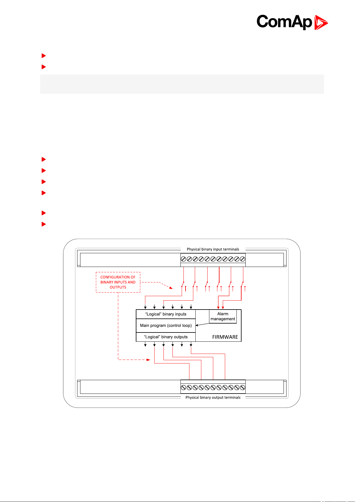
The firmware of controller contains a large number of binary inputs and outputs needed forall necessary
functions available. However, not all functions are required at thesame time on thesame gen-set and also the
controller hardware does not have so many input and output terminals. One of the main tasks of the
configuration is mapping of “logical” firmware inputs and outputs to the “physical” hardware inputs and outputs.
2.3.2 Configuration parts
Mapping of logical binary inputs (functions) or assigning alarms to physical binary input terminals
Mapping of logical binary outputs (functions) to physical binary output terminals
Assigning sensor characteristics (curves) and alarms to analoginputs
Selection of peripheral modules, which are connected to the controller, and doing the same (as mentioned
above) for them
Selection of ECU type, if an ECU is connected
Changing the languageof the controller interface
Image 2.1 Principle of binary inputs and outputs configuration
The controller is shipped with a default configuration, which should be suitable for most standard applications.
This default configurationcan be changed only by using a PC with theInteliConfig software. See InteliConfig
documentation for details.
InteliLite9 Global Guide
12
Page 13
Once theconfiguration is modified, it canbe saved to a file for later usage with anothercontroller or for backup
purposes. The file is called archive and has the file extension .ail3. An archive contains a full image of the
controller at the time of saving (if the controller is online for the PC) except the firmware. Besides configuration it
also contains current adjustment of all setpoints, all measured values, a copy of the history log and a copy of the
alarm list.
The archive can be simply used for cloning controllers, i.e. preparingcontrollers with identical configuration and
settings.
2.4 PC Tools
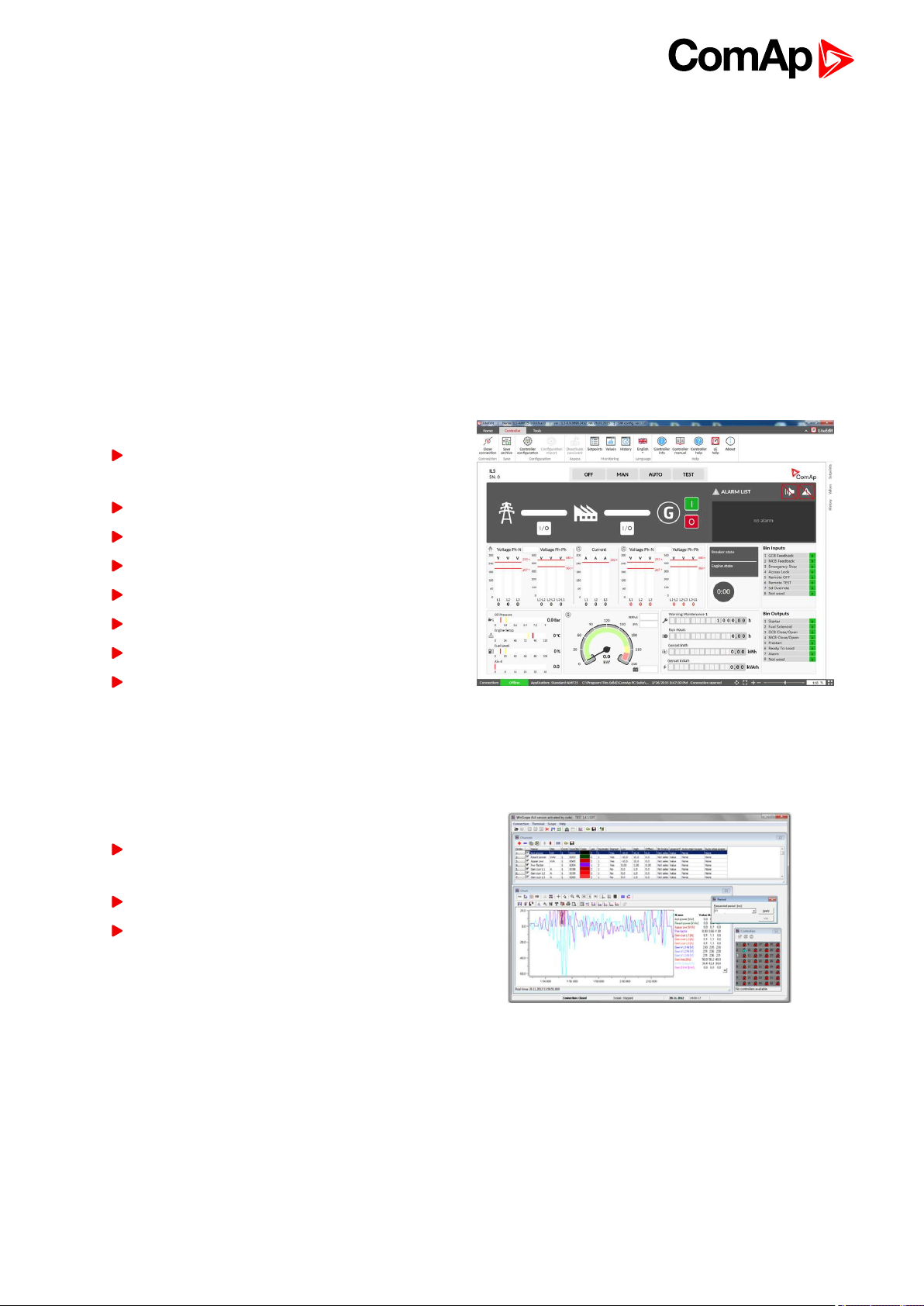
2.4.1 InteliConfig
Configurationand monitoring tool for InteliLite controllers. Seemore in InteliConfig Reference Guide.
This tool provides the following functions:
Direct or internet communicationwith the
controller
Offline or online controller configuration
Controller firmware upgrade
Reading/writing/adjustment of setpoints
Reading of measured values
Browsing of controller history records
Exportingdata into a XLS file
Controller language translation
2.4.2 WinScope
Special graphical controller monitoring software used mainly for commissioning and gen-set troubleshooting.
See more in the WinScope Reference guide.
This tool provides the following functions:
Monitoringand archiving of ComAp controller’s
parameters and values
View of actual / historical trends in controller
On-line change of controllers’ parameters for
easy regulator setup
InteliLite9 Global Guide
13
Page 14
2.5 Plug-in Modules
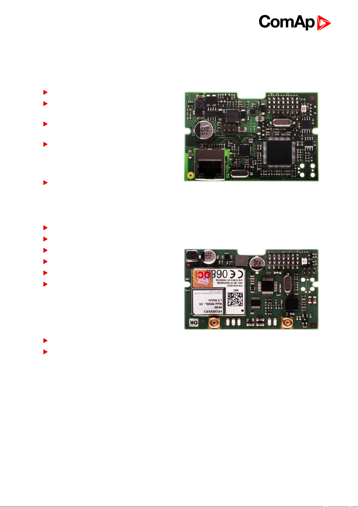
2.5.1 CM-Ethernet
Internet/Ethernet module includingweb server.
10/100 Mbit ethernet interface in RJ45 socket
Web interface formonitoring and adjustment of
the controller
Direct IP connection for remote access from
InteliConfig
MODBUS/TCP and SNMP protocols for
integrationof the controller into building
management systems or other remote
monitoringpurposes
Sending of active emails
2.5.2 CM-4G-GPS
GSM/4G Internet module and GPS locator
Wireless integrated solution
Quick and easy installation
Support of WebSupervisor
Instant alarm SMS notification
System control over SMS
Quad Band GPRS/EDGE modem,
850/900/1800/1900 MHz, FDD LTE: Band1,
Band 2, Band 3, Band 4, Band 5, Band7, Band
8, Band 20, all bands with diversity,
WCDMA/HSDPA/HSUPA/HSPA+: Band 1,
Band 2, Band 5, Band 8, all bands with diversity
GPRS multi-slot class 10
TCP/IP communication over GPRS
InteliLite9 Global Guide
14
Page 15
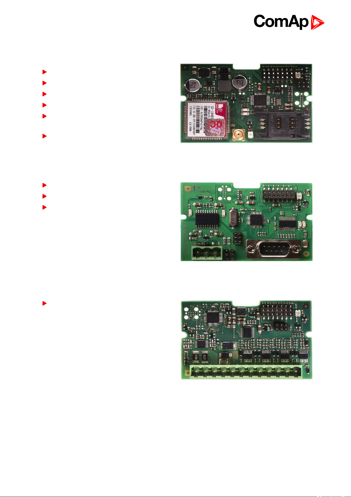
2.5.3 CM-GPRS
GSM/GPRS Internet module
Wireless integrated solution
Quick and easy installation
Instant alarm SMS notification
System control over SMS
Quad Band GPRS/EDGE modem,
850/900/1800/1900 MHz
GPRS multi-slot class 10
2.5.4 CM-RS232-485
Communication module with two communication ports.
RS232 and RS485 interface
MODBUS
Serial connection to InteliConfig
2.5.5 EM-BIO8-EFCP
Hybrid current input and binary input/output extension module.
Up to 8 additional configurable binary inputs or
outputs
6 back to System overview
InteliLite9 Global Guide
15
Page 16
3 Applications overview
3.1 AMF - Automatic Mains Failure Start 16
3.2 MRS - Manual Remote Start 16
6 back to Table of contents
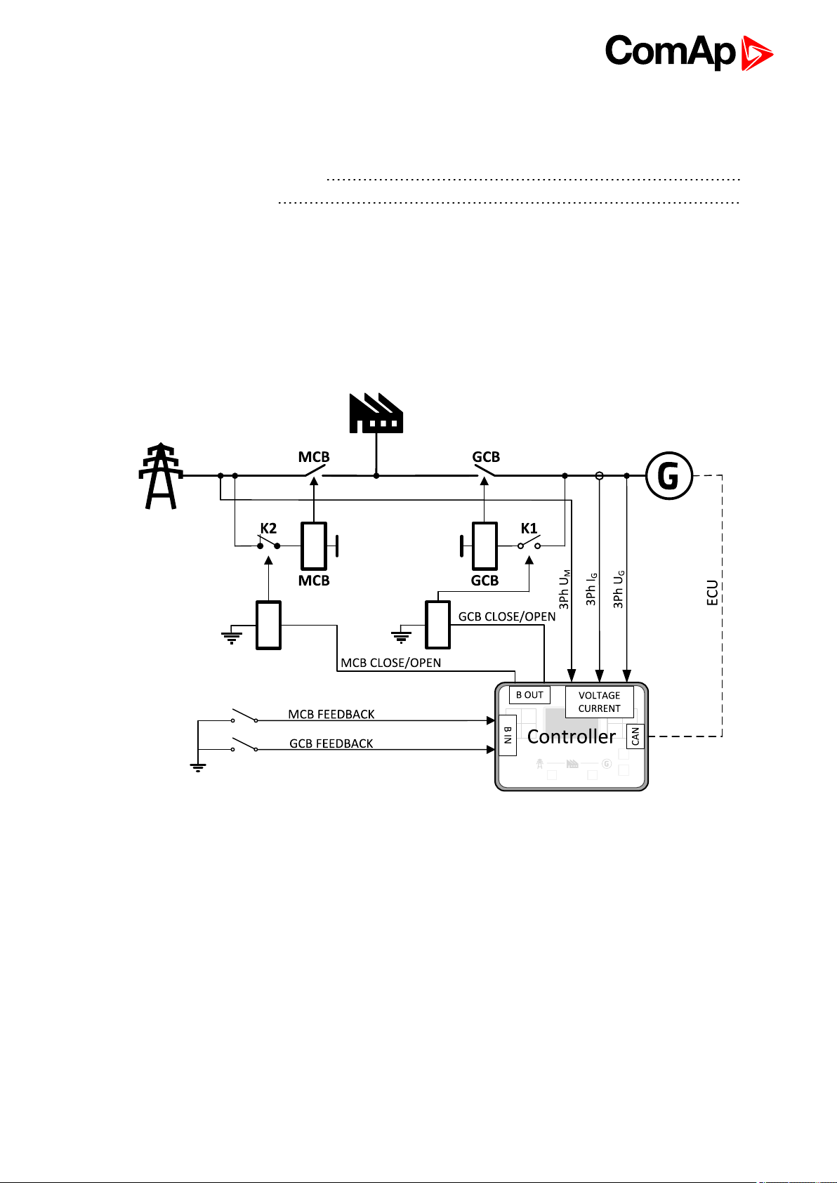
3.1 AMF - Automatic Mains Failure Start
The typical scheme of Automatic Mains Failure Start application is shown below. The controller controls two
breakers – a mains breaker and a generatorbreaker. Feedback from both breakers isn’t necessary. InteliLite
controllers can also work without breaker feedbacks.
Image 3.1 AMF application overview
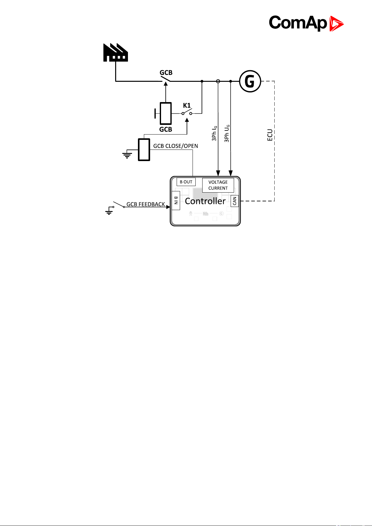
3.2 MRS - Manual Remote Start
The typical scheme of Manual Remote Start application is shown below. The controller controls one breaker – a
generator breaker. Feedback from breaker isn’t necessary. InteliLite controllers can also work without breaker
feedback.
InteliLite9 Global Guide
16
Page 17
6 back to Applications overview
Image 3.2 MRS application overview
InteliLite9 Global Guide
17
Page 18
4 Installation and wiring
4.1 Package content 18
4.2 Controller installation 18
4.3 Terminal Diagram 20
4.4 Recommendedwiring 21
4.5 Plug-in module installation 43
6 back to Table of contents
4.1 Package content
The package contains:
Controller
Mounting holders
Terminal blocks
Note: The package does not contain a communication or extension modules. The required modules should be
ordered separately.
4.2 Controller installation
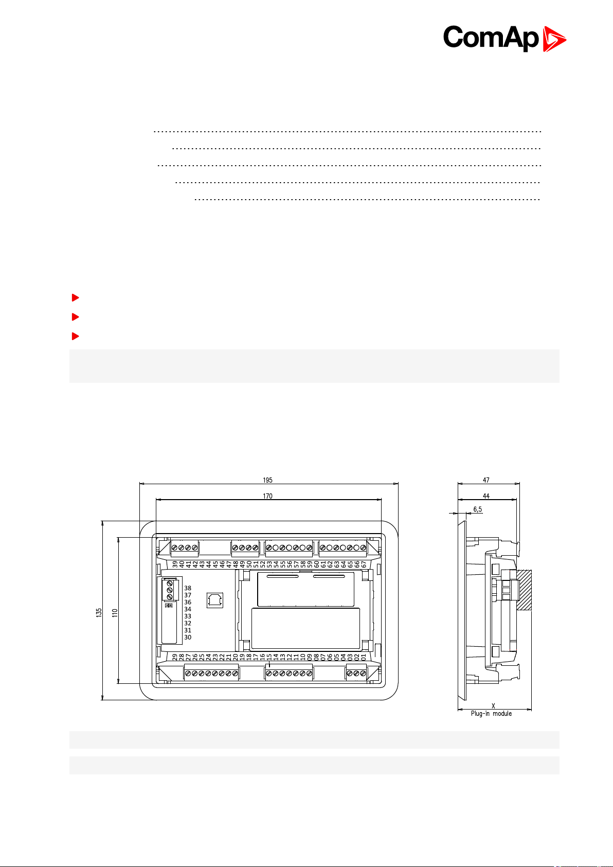
4.2.1 Dimensions
Note: Dimension x depends on plug-in module
Note: Dimensions are in millimeters
InteliLite9 Global Guide
18
Page 19

4.2.2 Mounting
The controller is to be mounted onto the switchboard door. Requested cutout size is 172x 112 mm. Use the
screw holders delivered with thecontroller to fix thecontroller into the dooras described on pictures
below.Recommended torque for holders is 0.15N·m.
Panel door mounting
Note: Enclosure Type rating with mounting instruction - For use on a Flat surface of a type 1 enclosure.
InteliLite9 Global Guide
19
Page 20
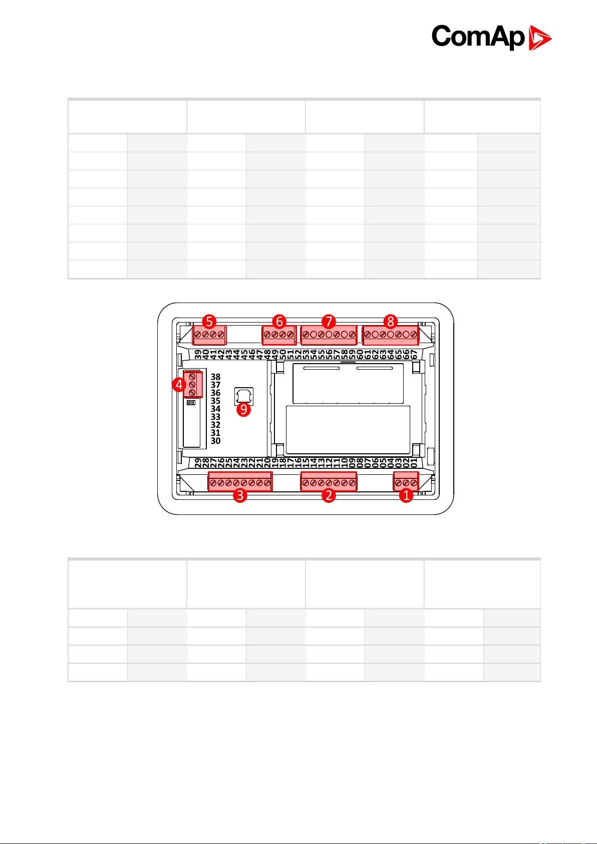
4.3 Terminal Diagram
① POWER SUPPLY,D+② BINARY OUTPUTS ③ BINARY INPUTS ④ CAN
T01 BATT- T09 E-STOP T20 RPM GND T36 CAN L
T02 D+ T10 BOUT1 T21 RPM IN T37 CAN COM
T03 BATT+ T11 BOUT2 T22 BIN1 T38 CAN H
T12 BOUT3 T23 BIN2
T13 BOUT4 T24 BIN3
T14 BOUT5 T25 BIN4
T15 BOUT6 T26 BIN5
T27 BIN6
Image 4.1 Terminal diagram for InteliLite 9 9
⑤ ANALOG INPUTS ⑥ GENERATOR
CURRENT
MEASUREMENT
T39 AIN COM T48 COM T53 N T61 N
T40 AIN1 T49 L1 T55 L1 T63 L1
T41 AIN2 T50 L2 T57 L2 T65 L2
T42 AIN3 T51 L3 T59 L3 T67 L3
InteliLite9 Global Guide
⑦ GENERATOR
VOLTAGE
MEASUREMENT
⑧ MAINS VOLTAGE
MEASUREMENT
20
Page 21

4.4 Recommended wiring
Power supply "+", D, "-" Power supply (page 22)
Binary outputs 09 - 15 Binary Outputs (page 33)
Binary inputs 22 - 27 Binary inputs (page 32)
CANbus H, COM, L CAN bus (page 38)CAN bus (page 38)
Analog inputs 39 - 42 Analog inputs (page 34)
Current inputs 48 - 51 Current measurement wiring (page 24)
Generator voltage inputs 53- 59
Mains voltage inputs 61 - 67 Voltage measurement AMF wiring (page 26)
USB USB (page 40)
Note: Wiring terminal markings to included tightening torque: 0,5 N-m (4,5 lb-in)., and wire size: 2 mm2(12-
26AWG).
Voltage measurement AMF wiring (page 26)
Voltage measurement MRS wiring (page 28)
InteliLite9 Global Guide
21
Page 22
4.4.1 General
To ensure proper function:
Use grounding terminals.
Wiring for binary inputs and analog inputs must not be run with power cables.
Analog and binary inputs should use shielded cables, especially when the length is more than 3m.
Tightening torque, allowable wire size and type, for the Field-Wiring Terminals:
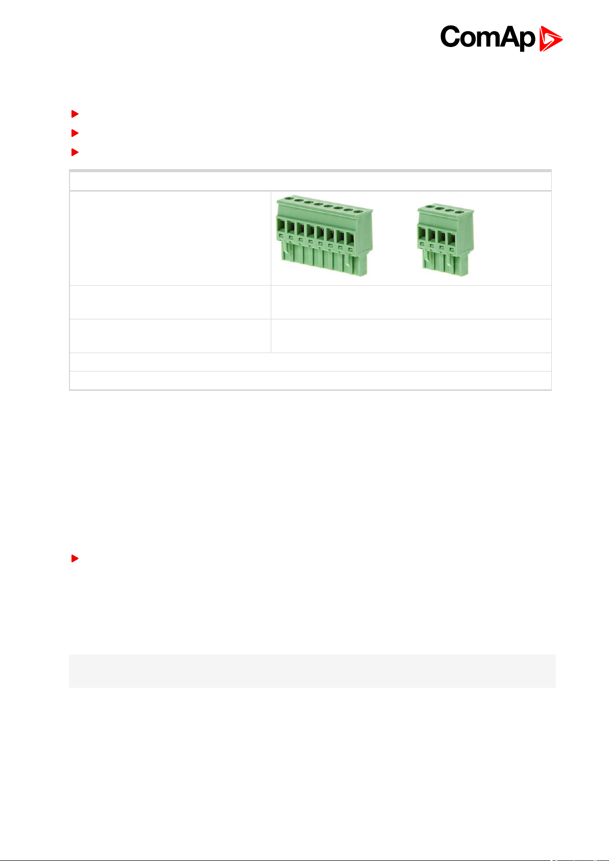
Example of used connectors:
For Mains and Generator Voltage, and for
Current terminals:
For other controller field wiring terminals: Use only diameter 2.0–0.5 mm (AWG 12–26)conductor, rated
Specified tightening torque is 0.56N·m (5.0In-lb).
Use copper conductors only.
Use only diameter 2.0–0.5 mm (AWG 12–26)conductor, rated
for 90°C minimum.
for 75°C minimum.
4.4.2 Grounding
The shortest possible length of wire shouldbe used for controller grounding. Use cable min 2.5mm2.
The negative " - " battery terminal must be properly grounded.
Switchboard and engine must be groundedat common point. Use as short cable as possible to the grounding
point.
4.4.3 Power supply
To ensure proper function:
Use power supply cable min. 1.5mm
Maximum continuous DC power supply voltage is 36V DC. The controller’s power supply terminals are
protected against large pulse power disturbances. When thereis a potential risk of the controller being subjected
to conditions outside its capabilities, an outside protection device should be used.
2
It is necessary to ensure that potential difference betweengenerator current COM terminal and battery “- ”
terminal is maximally ± 2V. Therefore is strongly recommended to interconnect these two terminals together.
Note: The controller should be grounded properly in order to protect against lighting strikes. The maximum
allowable current through the controller’s negative terminal is 4A (this is dependent on binary output load).
For the connections with 12 V DC power supply, the controller includes internal capacitors that allow the
controller to continue in operation duringcranking if the batter voltage dip occurs. If the voltage dip goes during
cranking to 0 V and after50 ms it recovers to 4 V, the controller continues operating. This cycle can repeat
several times. Duringthis voltage dip the controller screen backlight canturn off.
InteliLite9 Global Guide
22
Page 23

Note: Recommended fusing is 3 A fuse.
Note: In case of the dip to 0 V the high-side binary outputs will be temporarily switched off and after recovering
to 4 V back on.
IMPORTANT: When the controller is power up only by USB and the USB is disconnected then the
actual statistics can be lost.
Note: Suitable conductor protection shall be provided in accordance with NFPA 70, Article 240.
Note: Low voltage circuits (35 volts or less) shall be supplied from the engine starting battery or an isolated
secondary circuit.
Note: It is also possible to further support the controller by connecting the external capacitor and separating
diode. The capacitor size depends on required time. It shall be approximately thousands of μF. The capacitor
size should be 5 000μF to withstand 150 ms voltage dip under following conditions: Voltage before dip is 12V,
after 150ms the voltage recovers to min. allowed voltage, i.e. 8V.
Power supply fusing
A 3 A fuse should be connected in-line with the battery positive terminal to the controller and modules. These
items should never be connected directly to the starting battery. Fuse value and type depends on numberof
connected devices and wire length. Recommended fuse (not fast) type - T3 A. Not fast dueto internal
capacitors charging during power up.
Note: Recommended fusing is 3 A fuse.
4.4.4 Measurement wiring
Use 1.5 mm2cables for voltage connection and 2.5 mm2for current transformers connection. Adjust Connection
type (page 147), Nominal Voltage Ph-N (page 149), Nominal Voltage Ph-Ph (page 149), Nominal Current (page
146), PT Ratio (page 149), Vm PT Ratio (page 150) andCT Ratio (page 147) by appropriate setpoints in the Basic
Settings group.
InteliLite9 Global Guide
23
Page 24
IMPORTANT: Risk of personal injury due to electric shock when manipulating voltage terminals
under voltage. Be sure the terminals are not under voltage before touching them.
Do not open the secondary circuit of current transformers when the primary circuit is closed. Open
the primary circuit first.
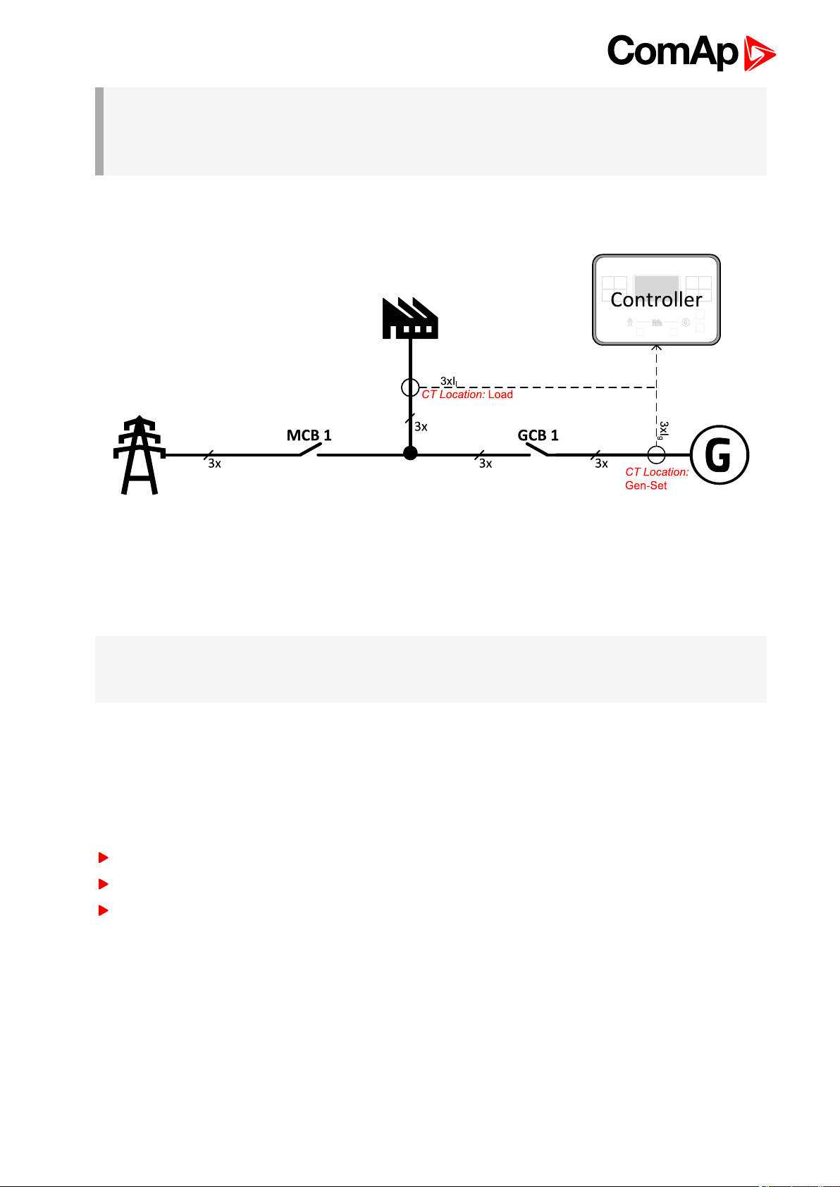
CT Location
Image 4.2 CT Location
There are two options of CT location.
a) Load
b) Gen-Set
Note: The current measurement protections are active only when the Gen-set is running.
If the CT Location is set to Load the Short Circuit BOC (page 193) protection is enabled only when GCB is
closed.
Current measurement wiring
The number of CT’s is automatically selected based on selected value of setpoint Connection type (page 147)
[3Ph4Wire/ High Leg D / 3Ph3Wire / Split Ph / Mono Ph].
Generator currents and powermeasurement is suppressed if current level is bellow <1 % of CT range.
To ensure proper function:
Use cables of 2.5 mm
Use transformers to 5 A
Connect CT according to following drawings:
2
InteliLite9 Global Guide
24
Page 25
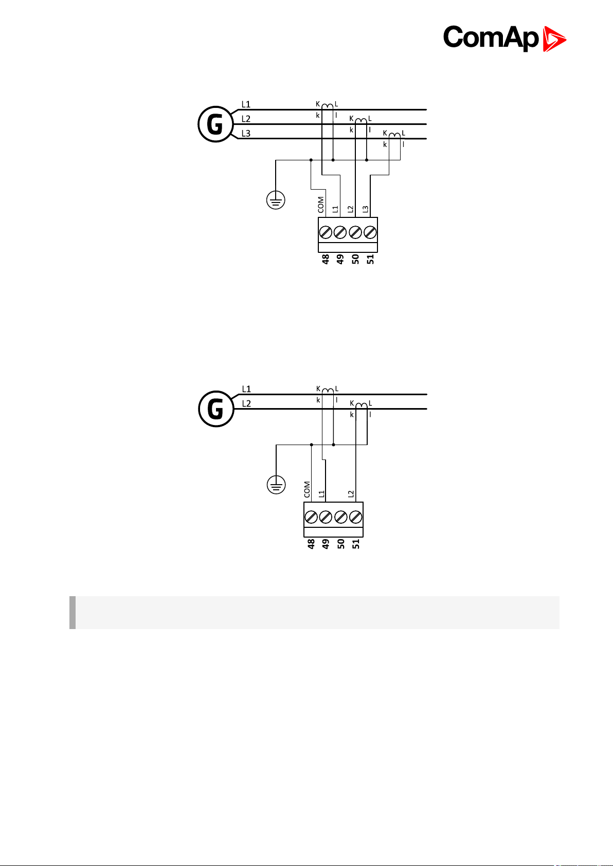
3 phase application:
Image 4.3 3 phase application
It is necessary to ensure that potential difference betweencurrent COM terminal andbattery “-” terminal is
maximally ± 2 V. Therefore is strongly recommended to interconnect these two terminals together.
Split phase application:
Image 4.4 Split phase application
IMPORTANT: The second phase of split phase connection is connected to the terminal, where is
normally connected the third phase.
InteliLite9 Global Guide
25
Page 26
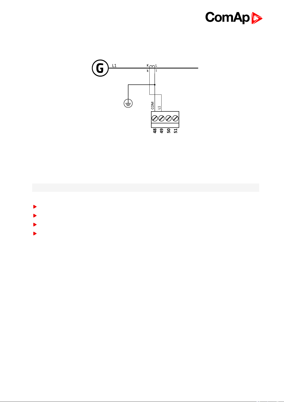
Mono phase application:
Connect CT according to following drawings. Terminals phase 2 and phase 3 are opened.
Image 4.5 Mono phase application
Voltage measurement AMF wiring
There are 4 voltage measurement Connection Type (setpoint Connection type (page 147) [3Ph4Wire /3Ph3Wire
/ Split Ph / Mono Ph]) options, every type matches to correspondinggenerator connection type.
Note: For fusing of voltage measurement input use T1A or T2A fuse.
The generator protections are evaluated from different voltages based on Connection type (page 147) setting:
3Ph 4W – Ph-Ph voltage, Ph-N voltage
3Ph 3W – Ph-Ph voltage
Split Ph – Ph-N voltage
Mono Ph – Ph-N voltage
InteliLite9 Global Guide
26
Page 27
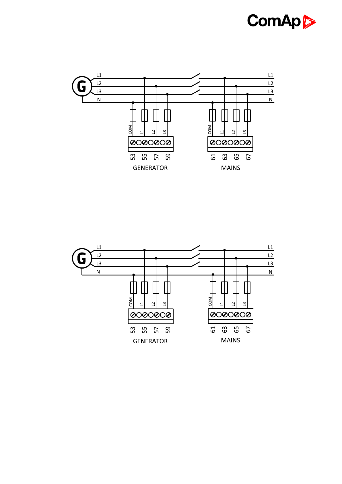
ConnectionType: 3 Phase 4 Wires
Image 4.6 3 phase application with neutral
ConnectionType: 3 Phase 3 Wires
InteliLite9 Global Guide
Image 4.7 3 phase application without neutral
27
Page 28
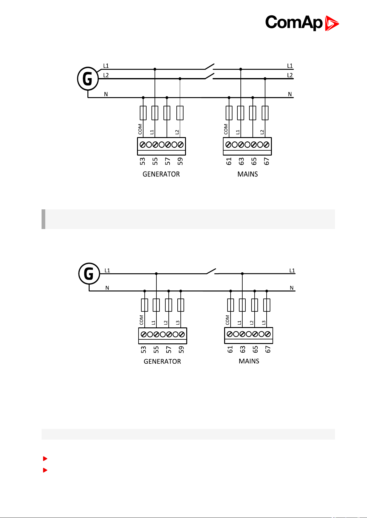
ConnectionType: Split Phase
Image 4.8 Split phase application
IMPORTANT: The second phase of split phase connection is connected to the terminal, where is
normally connected the third phase.
ConnectionType: Mono Phase
Image 4.9 Mono phase application
Voltage measurement MRS wiring
There are 4 voltage measurement Connection Type (setpoint Connection type (page 147) [3Ph4Wire /3Ph3Wire
/ Split Ph / Mono Ph]) options, every type matches to correspondinggenerator connection type.
Note: For fusing of voltage measurement input use T1A or T2A fuse.
The generator protections are evaluated from different voltages based on Connection type (page 147) setting:
3Ph 4W – Ph-Ph voltage, Ph-N voltage
3Ph 3W – Ph-Ph voltage
InteliLite9 Global Guide
28
Page 29
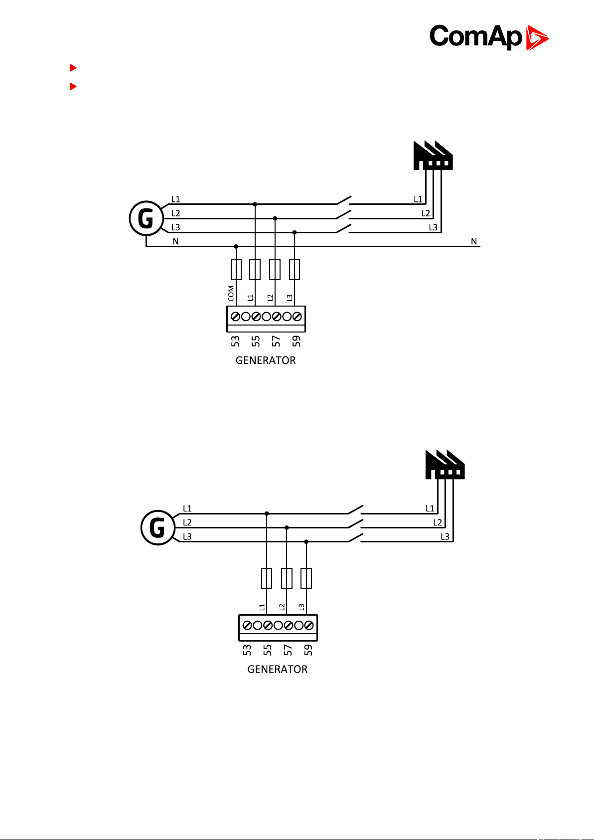
Split Ph – Ph-N voltage
Mono Ph – Ph-N voltage
ConnectionType: 3 Phase 4 Wires
Image 4.10 3 phase application with neutral
ConnectionType: 3 Phase 3 Wires
InteliLite9 Global Guide
Image 4.11 3 phase application without neutral
29
Page 30
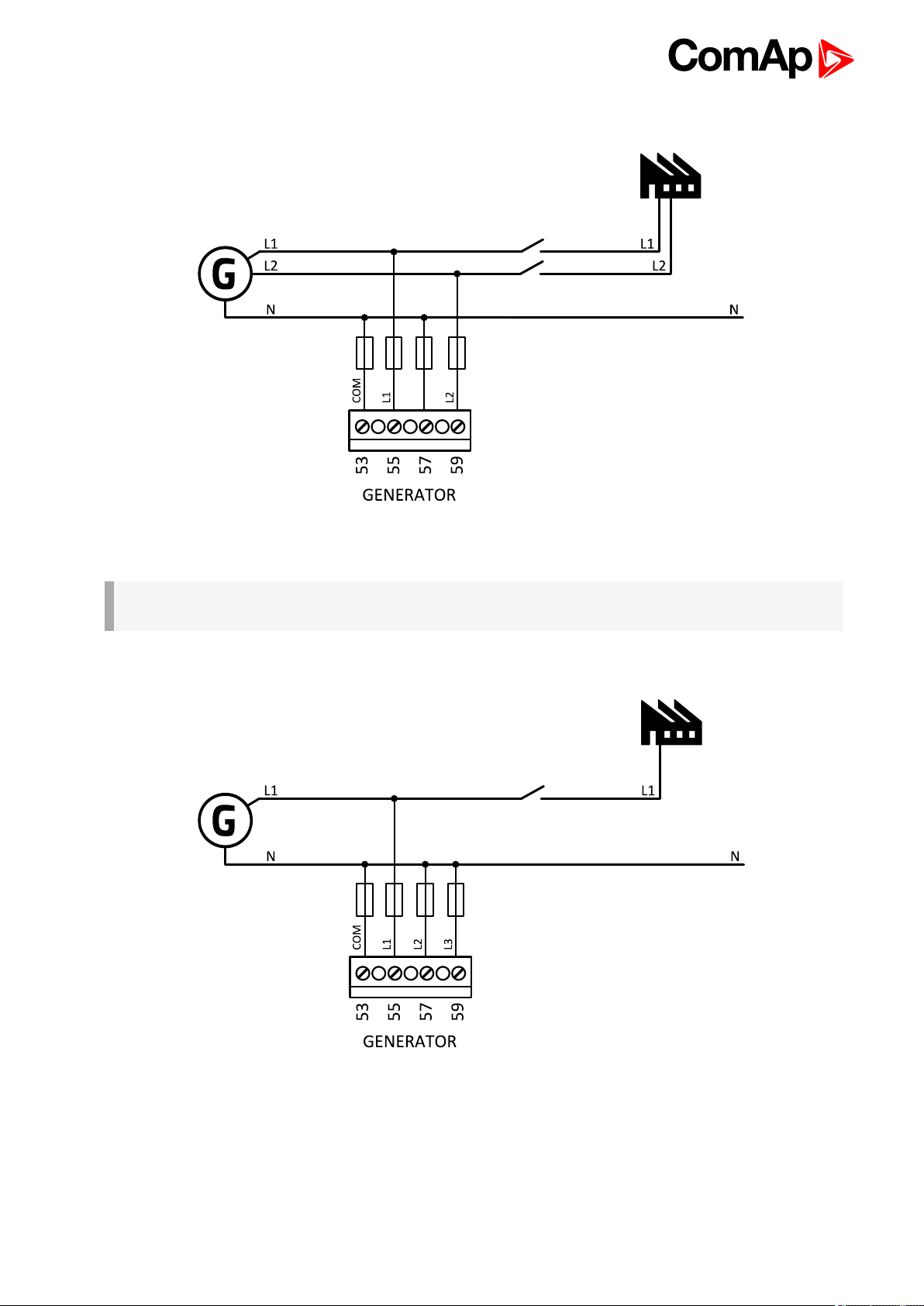
ConnectionType: Split Phase
Image 4.12 Split phase application
IMPORTANT: The second phase of split phase connection is connected to the terminal, where is
normally connected the third phase.
ConnectionType: Mono Phase
Image 4.13 Mono phase application
4.4.5 Magnetic pick-up
A magnetic speedsensor (pickup) is the most common method of engine speed measurement. To use this
method, mount the pickup opposite to theengine flywheel, connect the cable to the controller as shown on the
InteliLite9 Global Guide
30
Page 31

picture below and adjust the setpoint Gear Teeth (page 151) according to the number of teeth on the flywheel.
For the details about thepick-up input parameters see Technical data on page 137
IMPORTANT: To ensure proper function use a shielded cable.
If engine will not start:
Check ground connection from pick-up to controllers, eventually disconnect ground connection to one of
them.
Note: In some cases the controller will measure a RPM value even though the gen-set is not running: RPM is
measured from the generator voltage (Gear Teeth = 0). Controller is measuring some voltage value on input
terminals due to open fusing. If RPM > 0 the controller will be put into a Not ready state and the engine will not
be allowed to start.
InteliLite9 Global Guide
31
Page 32

4.4.6 Binary inputs
Use minimally 1 mm2cables for wiring of Binary inputs.
Image 4.14 Wiring binary inputs
Note: The name and function or alarm type for each binary input have to be assigned during the configuration.
InteliLite9 Global Guide
32
Page 33

4.4.7 Binary Outputs
Use min. 1 mm2cables for wiring of binary outputs. Use external relays as indicated on the schematic below for
all outputs except those where low-current loads are connected (signalization etc...).
IMPORTANT: Use suppression diodes on all relays and other inductive loads!
Note: Every single low current binary output can provide up to 0,5 A of steady current.
Note: Binary output 1 (terminal 4) and binary output 2 (terminal 5) are high current outputs (5 A for long term).
IMPORTANT: When operating temperature is higher than 60 °C it is strongly recommended to limit
output current of high current binary outputs (terminal 4 and terminal 5) to 4 A (each).
InteliLite9 Global Guide
33
Page 34

4.4.8 E-Stop
E stop has dedicatedterminal T09. Power supply of binary output 1 and binary output 2 (terminals 4 and 5) is
internally connected (in controller) to E-Stop terminal. It means higher security and faster disconnection of these
outputs. More information about E-Stop functions see E-Stop on page 109.
Note: This function has the same behavior as binary input EMERGENCY STOP (PAGE 305).
Image 4.15 E-Stop wiring
Note: Recommended fusing is 12 A fuse.
Note: Grey dashed line symbolizes internal connection between E-Stop and binary outputs 1 and 2.
Note: For proper functionality of E-Stop, the terminal T09 must be always wired. Terminal can be connected to
battery+ or to terminal T03 (BATT+)
IMPORTANT: Suppression diodes are not indicated, but required.
4.4.9 Analog inputs
The analog inputs aredesigned for resistive automotive type sensors like VDO or DATCON. The sensors are
connected eitherby one wire (the second pole is the sensor body) or by two wires.
In the case of grounded sensors, connect the AI COM terminal to the engine body as near to the sensors as
possible.
In the case of isolated sensors, connect the AI COM terminal to the negative power supply terminal of the
controller as well as onepole of each sensor.
InteliLite9 Global Guide
34
Page 35

Analog inputs aretypically used for: Oil Pressure, Coolant Temperature andFuel Level. All of these parameters
areconnected with relevant protections.
Image 4.16 Grounded sensors Image 4.17 Isolated sensors
Note: Schemes show only analog input connection overview, not actual wiring.
Note: The name, sensor characteristic and alarm types for each analog input have to be assigned during
configuration.
Analog inputs with voltage & current sensors
On each analog input, there is a possibility to connect voltage or current output sensor instead of resistive one.
Recommended wiring connection for these measurements and recommendedcurves are bellow.
Voltage sensors
Sensor’s output
range (V)
0 - 10 390 100
0 - 30 1500 100
0 - 70 3300 100
R1 (Ω) R2 (Ω)
InteliLite9 Global Guide
35
Page 36

Image 4.18 Wiring of analog input with voltage sensor
0 - 10 V
V 0 1 2 3 4 5 6 7 8 9 10
Ω 81 145 219 306 409 539 685 887 1125 1458 1933
0 - 30 V
V 0 2 4 6 8 10 12 14
Ω 95 134 177 223 274 330 395 465
V 16 18 20 22 24 26 28 30
Ω 543 633 735 853 993 1154 1350 1589
0 - 70 V
V 0 2 4 6 8 10 12 14 16 18 20 22
Ω 99 117 137 155 175 196 219 242 266 291 318 346
V 24 26 28 30 32 34 36 38 40 42 44 46
Ω 375 406 439 473 510 549 589 633 679 729 781 838
V 48 50 52 54 56 58 60 62 64 66 68 70
Ω 873 963 1033 1110 1193 1283 1383 1492 1612 1748 1896 2065
Note: This is a conversion of voltage from voltage sensor to appropriate resistance value. Use resistance
values in InteliConfig to create your specific curve. These values should be used in "Ohm" column.
Current sensors
Sensor’s output
range (mA)
0-20 100
InteliLite9 Global Guide
R (Ω)
36
Page 37

Image 4.19 Wiring of analog input with current sensor
0 - 22 mA
mA 0 1 2 3 4 5 6 7 8 9 10 11
Ω 100 133 167 202 241 283 328 375 431 489 553 625
mA 12 13 14 15 16 17 18 19 20 21 22
Ω 707 793 894 1007 1136 1287 1460 1666 1914 2222 2596
Note: This is a conversion of current from current sensor to appropriate resistance value. Use resistance
values in InteliConfig to create your specific curve. These values should be used in "Ohm" column.
InteliLite9 Global Guide
37
Page 38

Analog as binary or tristate inputs
Analog inputs can be used also as binary or tri-state, i.e. for contact sensors without or with circuit check. The
threshold level is 750Ω. In the case of tri-state, values lower than 10Ω and values over 2400Ω are evaluated as
sensor failure (short or open circuit).
Image 4.20 Analog inputs as tristate Image 4.21 Analog inputs as binary
Note: The name, sensor characteristic and alarm types for each analog input have to be assigned during
configuration.
Note: Tristate and binary sensors are not suitable for Analog Switch functions.
4.4.10 CAN bus
CAN bus wiring
The wiring of the CAN bus should be provided in such a way that the following rules are observed:
The maximum length of the CAN bus depends on the communication speed. For a speed of 250 kbps, which
is used on the CAN1 bus (extensionmodules, ECU) and CAN2 bus if it is switched to 32C mode, the
maximum length is 200 m. If the CAN2 bus is switched to 8C mode the speed is 50 kbps and the maximum
length is 800 m.
The bus must be wired in linear form with termination resistors at both ends. No nodes are allowed except on
the controller terminals.
Shielded cable1has to be used, shielding has to be connected to the terminal T01 (BATT -).
External units can be connected on the CAN bus line in any order, but keeping line arrangement (no tails, no
star) is necessary.
The CAN bus has to be terminated by 120Ohm resistors at both ends use a cable with following
parameters:
1
Recommended data cables: BELDEN (http://www.belden.com) - for shorterdistances: 3105A Paired - EIA
Industrial RS-485 PLTC/CM (1x2 conductors); for longer distances: 3106A Paired - EIA Industrial RS-485
PLTC/CM (1x2+1 conductors)
InteliLite9 Global Guide
38
Page 39

Cable type Shielded twisted pair
Impedance 120Ω
Propagation velocity ≥ 75% (delay ≤ 4,4 ns/m)
Wire crosscut ≥ 0,25 mm
2
Attenuation (@1MHz) ≤ 2dB/100m
Note: Communication circuits shall be connected to communication circuits of Listed equipment.
Note: A termination resistor at the CAN (120Ω) is already implemented on the PCB. For connecting, close the
jumper near the appropriate CAN terminal.
Image 4.22 CAN bus topology
For shorterdistances (connection within one building)
Image 4.23 CAN bus wiring for shorter distances
InteliLite9 Global Guide
39
Page 40

For longer distances or in case of surge hazard (connection out of building, in case of storm etc.)
Image 4.24 CAN bus wiring for longer distances
① RecommendedPT5-HF-12DC-ST
1
4.4.11 USB
This is required for computer connection. Use the shielded USB A-B cable.
Image 4.25 USB connection
Controller can by also power by USB (only for service purpose like a uploading firmware, change of
configuration etc.).
IMPORTANT: Power supply by USB is only for service purpose. Binary inputs and outputs are in
logical 0. Also plug-in modules are not working.
1
Protections recommended: Phoenix Contact (http://www.phoenixcontact.com): PT 5-HF-12DC-ST with PT2x2-
BE (base element) or Saltek (http://www.saltek.cz): DM-012/2 R DJ
InteliLite9 Global Guide
40
Page 41

4.4.12 Example of AMF Wiring
InteliLite9 Global Guide
41
Page 42

4.4.13 Example of MRS Wiring
InteliLite9 Global Guide
42
Page 43

4.5 Plug-in module installation
4.5.1 Installation
Remove the back cover. To do this, press four holders which are located in corners.
After removingback coverinsert the plug-in module. Plug-in modulehas to be inserted under holders. Start with
holders marked by symbol 1. On the controller are also arrows for better navigation. After inserting plug-in
module underholders 1 press it down to holders marked by symbol 2 which locks the module.
InteliLite9 Global Guide
43
Page 44

After locking theplug-in module into holders, place back the back cover (small cover for connectors has to be
removed from back cover). Finally insert the small coverfor connectors. Small covers are unique for each plugin module.
6 back to Installation and wiring
InteliLite9 Global Guide
44
Page 45

5 Controller setup
5.1 Default configuration 45
5.2 Controller configuration and PC tools connection 46
5.3 Operator Guide 50
5.4 Functions 74
6 back to Table of contents
5.1 Default configuration
5.1.1 Binary inputs AMF
Number Description Configured function
BIN1 Generator circuit breaker feedback GCB FEEDBACK (PAGE 307)
BIN2 Mains circuit breaker feedback MCB FEEDBACK (PAGE 309)
BIN3 Switch controller to OFF mode REMOTE OFF (PAGE 311)
BIN4 Switch controller to TEST mode REMOTE TEST (PAGE 313)
BIN5 Suppression of alarms SD OVERRIDE (PAGE 313)
BIN6 Binary input function used as alarm BIN PROTECTION 1 (PAGE 296)
5.1.2 Binary outputs AMF
Number Description Function
BOUT1 Starter motor control STARTER (PAGE 344)
BOUT2 Fuel solenoid valve FUEL SOLENOID (PAGE 326)
BOUT3 Generator circuit breakercontrol GCB CL OSE/OPEN (PAGE 327)
BOUT4 Mains circuit breaker control MCB CL OSE/OPEN (PAGE 335)
BOUT5 Activation of any devices before start PRESTART (PAGE 341)
BOUT6 Indicationof unconfirmed alarm ALARM (PAGE 322)
5.1.3 Binary inputs MRS
Number Description Function
BOUT1 Start and stop thegen-set in AUTO mode. REMOTE START/STOP (PAGE 312)
BOUT2 Generator circuit breakerfeedback GCB FEEDBACK (PAGE 307)
BOUT3 Switch controller to OFF mode REMOTE OFF (PAGE 311)
BOUT4 Switch controller to AUTO mode REMOTE AUTO (PAGE 310)
BOUT5 Suppression of alarms SD OVERRIDE (PAGE 313)
BOUT6 Binary input function used as alarm BIN PROTECTION 1 (PAGE 296)
InteliLite9 Global Guide
45
Page 46

5.1.4 Binary outputs MRS
Number Description Function
BOUT1 Starter motor control STARTER (PAGE 344)
BOUT2 Fuel solenoid valve FUEL SOLENOID (PAGE 326)
BOUT3 Generator circuit breakercontrol GCB CL OSE/OPEN (PAGE 327)
BOUT4 Activation of any devices before start PRESTART (PAGE 341)
BOUT5 Gen-set can be connected to load READY TO LOAD (PAGE 343)
BOUT6 Indicationof unconfirmed alarm ALARM (PAGE 322)
5.1.5 Analog inputs
Number Configured sensor Function
AIN1 VDO 10 Bar OIL PRESSURE (PAGE 355)
AIN2 VDO40-120°C COOLANT TEMP (PAGE 353)
AIN3 VDOLevel % FUEL LEVEL (PAGE 354)
5.2 Controller configuration and PC tools connection
5.2.1 USB 46
5.2.2 RS232/RS485 47
5.2.3 Ethernet 49
6 back to Controller setup
This chapter contains brief introduction into the specifics of firmwareand archive upload andconnection of
various PC tools to the controller. If you require detailed information on each PC tool please use the included
Help in those PC tools or download their Reference Guides.
5.2.1 USB
You may connect to the controller using the USB port. In this case standard USB A to B cable shouldbe used.
InteliLite9 Global Guide
46
Page 47

Connection using InteliConfig
Image 5.1 First screen of InteliConfig - select connect to controller
Image 5.2 Second screen of InteliConfig - select detected controllers
Connection using WinScope
Image 5.3 WinScope screen - select direct connection
5.2.2 RS232/RS485
It is possible to connect to the controller using RS232 or RS485 direct connection (serial port or USB to
RS232/RS485converter may beused). Thefollowing settings need to be checked in the controller:
COM1 Mode (page 221) = Direct
Controller Address (page 154) has to be set to the same value as in the PC tool
InteliLite9 Global Guide
47
Page 48

Connection using InteliConfig
Image 5.4 First screen of InteliConfig - select connect to controller
InteliLite9 Global Guide
Image 5.5 Second screen of InteliConfig - select Serial link
48
Page 49

Connection using WinScope
Image 5.6 WinScope screen - select direct connection
Note: Winscope supports only 19200, 38400, 57600 speeds.
5.2.3 Ethernet
It is possible to connect to the controller using ethernet port.
Direct connection
When you use direct connection the controllerneeds to be reachable directly from the PC you use (i.e. one LAN
or WAN without any firewalls and other points that may not allow the connection). The following settings need to
be checked in the controller:
Controller Address (page 154) has to be set to the same value as in the PC tool
IP Address Mode (page 235) can be set to AUTOMATIC when there is DHCP service is available. Otherwise
it needs to be set to FIXED
IP Address (page 236) is either set automatically or it can be adjusted to a specific requested value
Subnet Mask (page 236) is either set automatically or it can be adjusted to a specific requested
Gateway IP (page 237) can be set here when it is used
Connection using InteliConfig
InteliLite9 Global Guide
Image 5.7 First screen of InteliConfig - select connect to controller
49
Page 50

Image 5.8 Second screen of InteliConfig - select Internet/Ethernet
Connection using WinScope
Image 5.9 WinScope screen
5.3 Operator Guide
5.3.1 Front panel elements 51
5.3.2 Display screens and pages structure 52
5.3.3 Browsing alarms 65
5.3.4 Password 66
InteliLite9 Global Guide
50
Page 51

5.3.5 Information screen 72
5.3.6 Language selection 73
5.3.7 Display contrast adjustment 74
5.3.1 Front panel elements
Image 5.10 Operator interface of InteliLite 9
Control buttons
Position Picture Description
LEFT button. Use this button to move left or to change the mode. Thebutton can
change the mode only if the main screen with the indicator of currently selected
mode is displayed.
Note: This button will not change the mode if the controller mode is forced by
one of binary inputs listed in the Reference Guide – “Operating modes” chapter.
RIGHT button. Use this button to move right or to change the mode. Thebutton
can change the mode only if the main screenwith the indicator of currently
selected mode is displayed.
Note: This button will not change the mode if the controller mode is forced by
one of binary inputs listed in the Reference Guide – “Operating modes” chapter.
HORN RESET button. Use this button to deactivate thehorn output without
acknowledgingthe alarms.
InteliLite9 Global Guide
51
Page 52

FAULT RESET button. Use this button to acknowledge alarms and deactivate
the horn output. Inactive alarms will disappear immediately and status of active
alarms will be changed to "confirmed" so they will disappear as soonas their
reasons dismiss.
UP button. Use this button to move up or increase value.
PAGE button. Use this button to switch over display pages.
DOWN button. Use this button to move down or decrease value.
ENTER button. Use this button to finish editing a setpoint or moving right in the
history page.
START button. Works in MAN mode only. Press this button to initiate the start
sequence of the engine.
STOP button. Works in MAN mode only. Press this button to initiate the stop
sequence of the gen-set. Repeated pressing of button will cancel current phase
of stop sequence (like cooling) and next phase will continue.
Indicators and others
Position Description
GENERATOR status indicator. There are two states - Gen-set OK (indicator is green) and
Gen-set failure (indicatoris red). Green LED is on if the generator voltage is present and
within limits. Red LED starts flashing when gen-set failure occurs. After FAULT RESET
button is pressed, goes to steady light (if an alarm is still active)or is off (if no alarm is active).
MAINS status indicator. There are two states - Mains OK (indicator is green) and Mains
failure(indicator is red). Green LED is on, if mains is present and within limits. Red LED
starts blinking when the mains failure is detected and after the gen-set has started and
connected to theload it lights permanently until the mains failure disappears.
Graphic B/W display, 132x64 pixels.
GCB ON. Green LED is on if GCB is closed. It is driven by GCB CLOSE/OPEN output or by
GCB feedback signal.
GCB button. Works in MAN andTEST modes only. Press this button to open or
close the GCB.
MCB button. Works in MAN and TEST modes only. Press this button to open or
close the MCB.
MCB ON. GreenLED is on if MCB is closed. It is drivenby MCB CLOSE/OPEN output or by
MCB feedback signal.
5.3.2 Display screens and pages structure
The displayed information is structured into "pages" and "screens". Use PAGE button to switch over the pages.
InteliLite9 Global Guide
52
Page 53

The page Measurement consists of screens which display measured values like voltages, current, oil
pressure etc., computedvalues like i.e. gen-set power, statistic data and the alarm list on the last screen.
The page Setpoints contains all setpoints organized to groups and also a special group for entering
password.
The page History log shows the history log in the order that thelast record is displayed first.
Main Screen
Symbols
Padlock - active when LBI ACCESS LOCK is active
R - active when thereis active remote connection to controller
Exclamation mark - active when there is any alarm in alarmlist
Measurement Screens
Note: Use Up and Down button to move between measurement pages.
InteliLite9 Global Guide
53
Page 54

Note: Use Up and Down button to move between measurement pages.
Note: Use Up and Down button to move between measurement pages.
Note: Use Up and Down button to move between measurement pages.
Note: Use Up and Down button to move between measurement pages.
InteliLite9 Global Guide
54
Page 55

Note: Use Up and Down button to move between measurement pages.
Note: Use Up and Down button to move between measurement pages.
Note: Use Up and Down button to move between measurement pages.
Note: Use Up and Down button to move between measurement pages.
InteliLite9 Global Guide
55
Page 56

Note: Use Up and Down button to move between measurement pages.
Note: Use Up and Down button to move between measurement pages.
Note: Use Up and Down button to move between measurement pages.
Note: Use Up and Down button to move between measurement pages.
InteliLite9 Global Guide
56
Page 57

Note: Use Up and Down button to move between measurement pages.
Note: Use Up and Down button to move between measurement pages.
Note: Use Up and Down button to move between measurement pages.
Note: Use Up and Down button to move between measurement pages.
InteliLite9 Global Guide
57
Page 58

Note: Use Up and Down button to move between measurement pages.
Note: Use Up and Down button to move between measurement pages.
Note: Use Up and Down button to move between measurement pages.
Note: Use Up and Down button to move between measurement pages.
InteliLite9 Global Guide
58
Page 59

Note: Use Up and Down button to move between measurement pages.
Note: Use Up and Down button to move between measurement pages.
Note: From all of these pages it is possible to switch seamlessly to the setpoint group page by pressing Page
button.
Note: There can be some additional screens and also some screens can be hidden. Screen’s visibility
depends on actual configuration (usage of extension or communication modules, ECU, etc.).
Setpoint Screens
Note: From all measurement pages we can fluently go to the setpoint group page by pressing Page button.
InteliLite9 Global Guide
59
Page 60

Note: Use Enter button to enter selected setpoint group.
Note: Use Up and
Down button to
select required
setpoint group.
Note: Use Left and Right button to select required setpoint.
Note: Use Enter button to enter selected setpoint.
Note: Use Enter button to confirm adjusted value of setpoint.
Note: Use Up and
Down button to set
required value of
selected setpoint.
Note: Use Page button to discard changes, to set setpoint to previous value and to return to the list of
setpoints of selected group.
IMPORTANT: Cannot change setpoint? Setpoints marked with an padlock are password protected.
Enter password as described in the chapter Password (page 66).
InteliLite9 Global Guide
60
Page 61

History Log
Note: From all measurement pages we can fluently go to the setpoint group page by pressing Page button.
Note: From setpoint group page we can fluently go to the history log pages by pressing Page button.
Note: Use Up and
Down button to
select required
alarm reason.
Note: Use Enter button to move to the next page of history log.
Note: Use Up and
Down button to
select required
alarm reason.
Note: Use Enter button to move to the next page of history log.
InteliLite9 Global Guide
61
Page 62

Note: Use Enter button to move to the next page of history log.
Note: Use Up and
Down button to
select required
alarm reason.
Note: Use Up and
Down button to
select required
alarm reason.
Note: Use Enter button to move to the next page of history log.
Note: Use Enter button to move to the next page of history log.
Note: Use Up and
Down button to
select required
alarm reason.
Note: Use Up and
Down button to
select required
alarm reason.
Note: Use Enter button to move to the next page of history log.
InteliLite9 Global Guide
62
Page 63

Note: Use Enter button to move to the next page of history log.
Note: Use Up and
Down button to
select required
alarm reason.
Note: Use Up and
Down button to
select required
alarm reason.
Note: Use Enter button to move to the next page of history log.
Note: Use Enter button to move to the next page of history log.
Note: Use Up and
Down button to
select required
alarm reason.
Note: Use Up and
Down button to
select required
alarm reason.
Note: Use Enter button to move to the next page of history log.
InteliLite9 Global Guide
63
Page 64

Note: Use Enter button to move to the next page of history log.
Note: Use Up and
Down button to
select required
alarm reason.
Note: Use Up and
Down button to
select required
alarm reason.
Note: Use Enter button to move to the next page of history log.
Note: Use Enter button to move to the next page of history log.
Note: Use Up and
Down button to
select required
alarm reason.
Note: Use Up and
Down button to
select required
alarm reason.
Note: Use Enter button to move to the first page of history log.
InteliLite9 Global Guide
64
Page 65

IMPORTANT: The records are numbered in reverse order, i.e. the latest (newest) record is "0" and
older records have "-1", "-2" etc.
Note: This is only basic history record. There can be some additional screens in case that in controller is
extension module or ECU is configured. Also it depends on connection type.
5.3.3 Browsing alarms
Note: Use Up button to move to alarmlist from main measurement screen.
Active alarms are displayed as white text on black background. It means the alarm is still active, i.e. the
appropriate alarm conditions are still present.
Inactive alarms are displayed as black text on white background. It means the alarm is no more active, i.e.
the appropriate alarm conditions are gone.
Not confirmed alarms are displayed with an asterisk. It means the alarm is still not acknowledged
(confirmed).
ECU alarms: SPN/FMI/OC/SC
SPN - Suspect parameter number
FMI - type of protection
OC - numberof errors
SC - source of error
InteliLite9 Global Guide
65
Page 66

5.3.4 Password
Enter password
Note: From all measurement pages we can fluently go to the setpoint group page by pressing Page button.
Note: Use Up and
Down button to
select setpoint
group Password.
Note: Use Enter button to enter setpoint group Password.
InteliLite9 Global Guide
66
Page 67

Note: Use Enter button to enter selected setpoint.
Note: Use Up and
Down button to
select Enter
Password.
Note: Use Up and
Down button to set
required value of
selected setpoint.
Note: Use Left and Right button to move between digits.
Note: Use Enter button to confirm the password or Page button to cancel entering the password.
Note: In case that invalid password is entered, the controller shows Invalid password screen. Use Page
button to go back to menu.
InteliLite9 Global Guide
67
Page 68

Change password
Note: From all measurement pages we can fluently go to the setpoint group page by pressing Page button.
Note: Use Up and
Down button to
select setpoint group
Password.
Note: Use Enter button to enter setpoint group Password.
Note: Use Enter button to enter selected setpoint.
Note: Use Up and
Down button to
select Change
Password.
Note: Use Up and
Down button to
select required level
of password.
Note: Use Enter button to enter selected setpoint.
InteliLite9 Global Guide
68
Page 69

Note: Use Left and Right button to move between digits.
Note: After setting new password use Enter button to confirm adjusted password.
Note: Use Up and
Down button to set
required value of
password.
Note: Use Up and
Down button to set
required value of
password again.
Note: Use Left and Right button to move between digits.
Note: After setting new password again use Enter button to confirm adjusted password or Page button to
discard changes and to cancel changing password.
Note: Before changing the password controller has to be unlocked. In case that controller is locked, the
controller shows Password required screen. In that case the password has to be entered before changing the
password.
InteliLite9 Global Guide
69
Page 70

Log out from controller
Note: From all measurement pages we can fluently go to the setpoint group page by pressing Page button.
Note: Use Up and
Down button to
select setpoint
group Password.
Note: Use Enter button to enter setpoint group Password.
Note: Use Enter button to enter selected setpoint.
Note: Use Up and
Down button to
select Enter
Password.
InteliLite9 Global Guide
70
Page 71

Note: Use Left and Right button to move between digits.
Note: Enter invalid password to log out from controller.
Note: Use Up and
Down button to set
required value of
selected setpoint.
Note: In case that invalid password is entered, the controller shows Invalid password screen. Use Page
button to go back to menu.
Lost Password
IMPORTANT: Display the information screen containing the serial number and password decode
number as described in the chapter Information screen (page 72) and send them to your local
distributor.
Password break protection
The controller password is protected against breaking by brute force. The protection works at every controller
interface separately.
1. When an invalid password is entered5 times after each other, independently on the time period elapsed
between the attempts, the controller will be blocked after the 5th unsuccessful attempt for 1 minute at the
particular interface.
2. While the controller is blocked it refuses any further attempts to enter password.
3. When unblocked again the controller accepts one attempt to enter password. If the password is incorrect
again the controller will be blocked for 2 minutes.
4. Each further attempt to enter invalid password will double the blocking time, but maximum blocking time is
20 minutes.
5. When incorrect password is entered100-times after each otherthe controlleris blocked foreverand the
password reset procedure is required to unblock it.
InteliLite9 Global Guide
71
Page 72

5.3.5 Information screen
+
Note: On Main measurement screen press Enter and Page button together. Enter button has to be pressed
first.
Note: Use Page button to move to the next page.
Note: Use Page button to move to the next page.
Note: Use Up button to move back to main measurement screen.
InteliLite9 Global Guide
72
Page 73

5.3.6 Language selection
+
Note: On Main measurement screen press Enter and Page button together. Enter button has to be pressed
first.
Note: Use Page button to move to the next page.
Note: Use Page button to move to the next page.
Note: Use Page button to move to the next page.
InteliLite9 Global Guide
73
Page 74

Note: Use Enter button to confirm selected language.
5.3.7 Display contrast adjustment
Note: Use Up and
down button to
select required
language.
+
Note: On any measurement screen press Enter and
Down button together for lower contrast.
Note: After setting a contrast, no another action is needed.
6 back to Controller setup
Note: On any measurement screen press Enter and
Up button together for higher contrast.
+
5.4 Functions
5.4.1 Start-stop sequence 75
5.4.2 AMF sequence 77
5.4.3 Operating Modes 78
5.4.4 Engine start 79
5.4.5 Stabilization 81
5.4.6 Connecting to load 81
InteliLite9 Global Guide
74
Page 75

5.4.7 MRS operation 81
5.4.8 AMF operation 81
5.4.9 Engine cool down and stop 82
5.4.10 Alarm management 83
5.4.11 History log 89
5.4.12 Breaker control 90
5.4.13 Exercise timer 93
5.4.14 Service timers 99
5.4.15 Flowchart 101
5.4.16 Additional running engineindications 102
5.4.17 Voltage phase sequence detection 102
5.4.18 Gen-set operation states 102
5.4.19 Sensor curves 105
5.4.20 Tier 4 Final 105
5.4.21 Alternate configuration 108
5.4.22 E-Stop 109
5.4.23 ECU Frequency selection 110
6 back to Controller setup
5.4.1 Start-stop sequence
State Condition of the transition Action Next state
Ready Start request
RPM > 2 orOil pressure >
Oil Pressure (page 162)
voltage > 10V or D+ voltage is
higher than
OFF Mode selected or Shutdown
alarm active
Not Ready RPM < 2, Oil pressure not
detected, Generatorvoltage < 10V,
D+ not Active no shutdown alarm
active, other than OFF Mode
selected
Prestart Prestart time elapsed FUEL SOLENOID (PAGE 326) on,
D+ Treshold (page 170)
Starting
or Generator
PRESTART (PAGE 341)onPrestart
Time (page 161)
STARTER (PAGE 344)
Cranking Time (page 160)
started
counter started
on,
Maximum
counter
Prestart
Stop (Stop
fail)
Not Ready
Ready
Cranking
Cranking RPM > Starting RPM STARTER (PAGE 344) off, PRESTART
(PAGE 341) off
D+ input activated or oil pressure
detected or Generator voltage >
InteliLite9 Global Guide
STARTER (PAGE 344) off, PRESTART
(PAGE 341) off
Starting
Cranking
75
Page 76

25% Nominal voltage
Maximum Cranking Time (page
, 1st attempt
160)
Maximum Cranking Time (page 160)
elapsed, last attempt
Crank pause
Starting
Running Stop request READY TO LOAD (PAGE 343)
Cranking Fail Pause (page 160)
elapsed
Idle Time (page 172)
any shutdown condition FUEL SOLENOID (PAGE 326) off,
all cranking attempts elapsed FUEL SOLENOID (PAGE 326) off,
elapsed
STARTER (PAGE 344) off, FUEL
SOLENOID (PAGE 326) off, STOP
SOLENOID (PAGE 345)
Fail Pause (page 160)
STARTER (PAGE 344) off, PRESTART
(PAGE 341) off
STARTER (PAGE 344) on, FUEL
SOLENOID (PAGE 326) on, STOP
SOLENOID (PAGE 345)
Cranking Time (page 160)
started
Minimal Stabilization Time (page 174)
and
Maximal Stabilization Time (page
counter started
175)
STOP SOLENOID (PAGE 345) on
STOP SOLENOID (PAGE 345) on
off,
Cooling Time (page 176)
started
on,
Cranking
timer started
off,
Maximum
counter
Crank
pause
Shutdown
(Start fail)
Cranking
Running
Shutdown
Shutdown
(Start fail)
Cooling
counter
RPM = 0 orany other shutdown
condition
GCB CLOSE/OPEN (PAGE 327)
closed
Loaded GCB CLOSE/OPEN (PAGE 327)
opened
RPM = 0 orany other shutdown
condition
Cooling
Stop RPM = 0, Oil pressure not
Cooling Time (page 176)
RPM = 0 orany other shutdown
condition
Start request READY TO LOAD (PAGE 343) on Running
detected, Generatorvoltage < 10V,
D+ not active
If at least one of enginerunning
indication is detected when
Time (page 176)
elapsed.
elapsed
Stop
READY TO LOAD (PAGE 343) off,
FUEL SOLENOID (PAGE 326) off
FUEL SOLENOID (PAGE 326) off,
STOP SOLENOID (PAGE 345) on,
READY TO LOAD (PAGE 343) off,
FUEL SOLENOID (PAGE 326) off,
STOP SOLENOID (PAGE 345) on
FUEL SOLENOID (PAGE 326) off,
STOP SOLENOID (PAGE 345) on
Shutdown
Loaded
Running
Shutdown
Stop
Shutdown
Ready
Stop (Stop
fail)
InteliLite9 Global Guide
76
Page 77

Note: If all generator parameters are OK and Minimal Stabilization Time (page 174) elapsed, indicates that GCB
is possible to close. In AUTO Mode GCB is closed in this moment automatically.
Note: The start-up sequence can be interrupted in any time by stop request
5.4.2 AMF sequence
State Condition of the transition Action Next state
Mains
operation
Mains failure Mains voltage and frequency
Mains failed or MCB FEEDBACK
(PAGE 309)
On (page 207)
Mains failed or MCB FEEDBACK
(PAGE 309)
On (page 207)
OK,
Mains Fail
Mains voltage and frequency
OK,
GenRun
Emergency Start Delay (page 200)
elapsed,
207)
Emergency Start Delay (page 200)
elapsed,
207)
dropout,
dropout,
MCB Opens On (page 207)
MCB Opens On (page 207)
MCB Opens On (page
= Mains Fail
MCB Opens On (page
= Gen Run
MCB Opens
= Mains Fail
MCB Opens
= Gen Run
MCB CLOSE/OPEN (PAGE 335)off,
Emergency Start Delay (page 200)
started
Emergency Start Delay (page 200)
started
After elapsing
=
MCB CLOSE/OPEN (PAGE 335) on
None Mains
=
Engine start sequence performed, then
GCB CLOSE/OPEN (PAGE 327) on
Engine start sequence performed, then
MCB CLOSE/OPEN (PAGE 335) off, time
delay
Transfer Delay (page 201)
andGCB CLOSE/OPEN (PAGE 327) on
MCB Close Delay (page 202)
timer
timer
performed
Mains
failure
Mains
failure
Mains
operation
operation
Island
operation
Island
operation
Island
operation
Mains return Mains failed Island
Note: Mains failed means mains over/under -voltage, over/under -frequency, voltage asymmetry (preset delay
must elapse)
Note: If during start-up sequence mains returns, then MCB is reclosed with delay MCB Close Delay (page 202)(if
opened, depending on MCB Opens On (page 207) setpoint) and start-up sequence is interrupted.
Note: If mains fails during stop procedure (cooling) again, stop sequence is interrupted, MCB opened and GCB
re-closed with Transfer Delay (page 201).
Mains voltage and frequency OK
Mains Return Delay (page 200)
elapsed
Mains Return Delay (page 200)
started
GCB CLOSE/OPEN (PAGE 327) off, then
after
Transfer Delay (page 201) MCB
CLOSE/OPEN (PAGE 335) on and then
engine stop sequence performed
timer
Mains return
operation
Mains
operation
InteliLite9 Global Guide
77
Page 78

5.4.3 Operating Modes
Selecting theoperatingmode is donethrough Left and Right buttons on the front panel or by changing the
Controller mode (page 152) setpoint (from the front panel or remotely).
Note: If this setpoint is configured as password-protected, the correct password must be entered prior to
attempting to change the mode.
Note: The mode cannot be changed if Access Lock input is active.
The following binary inputs can be used to force one respective operating mode independent of the mode
setpoint selection:
Remote OFF (page 311)
Remote TEST (page 313)
Remote MAN (page 311)
Remote AUTO (page 310)
If the respective input is active the controller will changethe mode to therespective position according to the
active input. If multiple inputs are active, the mode will be changed according to priorities of the inputs. The
priorities match theorder in the list above. If all inputs are deactivated, the mode will return to theoriginal
position given by the setpoint.
OFF
No start of the gen-set is possible .Controller stays in Not ready status and cannot be started any way. The
MCB is closed permanently (MCB Opens On (page 207) = GENRUN) or is open or closed according to whether
the mains is present or not (MCB Opens On (page 207) = MAINSFAIL). No AMF function will be performed. The
buttons MCB , GCB , Start andStop including the appropriate binary inputs forexternal buttons
arenot active.
IMPORTANT: When engine is running, it is not possible to switch gen-set to OFF mode.
MAN
The engine can be started and stopped manually using the Start andStop buttons (or external buttons
wired to theappropriate binary inputs) in MAN mode. When the engine is running, GCB can be closed. Also
MCB can be closedand opened manually using the MCB button, regardless of whether the mains are present or
not. No auto start is performed.
Note: The controller provides interlock between GCB and MCB, it means it is never possible to close both CB
together.
AUTO
The controller does not respondto buttons Start , Stop , MCB ON/OFF andGCB ON/OFF . Engine
start/stoprequest is evaluated form Mains failure/return.
Note: When the AMF function will start the engine than the engine will be running at least for the time which is
defined in Mains Return Delay (page 200) setpoint, even if the mains would return in the meantime.
InteliLite9 Global Guide
78
Page 79

TEST
The gen-set will be started when the controller is put to TEST mode and will remain running unloaded. If a mains
failureoccurs, the MCB will be opened and after Transfer Delay (page 201) the GCB will be closed and the genset will supply the load. After the mains have recovered, the delay Mains Return Delay (page 200)l will count
down and if it elapses and the mains is still ok, the controller will transfer the load back to the mains after
Transfer Delay (page 201) and the gen-set will remain runningunloaded again until the mode is changed.
Remote test on load
When binary input is closed, the controller automatically transfers load from the mains to thegen-set. SeeLBI
REM TEST ON LOAD (PAGE 312).
5.4.4 Engine start
Diesel engine
After the command for start is issued (pressing Start button in MAN mode, auto start condition is fulfilled in
AUTO mode or controller is switched to TEST mode), outputs PRESTART (PAGE 341) and GLOW PLUGS
(PAGE 332) are energized for time period given by the setpoints Prestart Time (page 161) and Glow Plugs Time
(page 162).
After Prestart Time (page 161) and Glow Plugs Time (page 162), the output FUEL SOLENOID (PAGE 326) is
energized and after Fuel Solenoid Lead (page 172) the starter of motor is activated by energizing the output
STARTER (PAGE 344).
When one or more of following conditions are met, the starter output is de-energized:
The engine speed exceeds the value of Starting RPM (page 161), or
Oneof Additional running engine indications (page 102) signals becomes active.
The controller remains in the Starting phase until the engine speed exceeds the value of Starting RPM (page
161), after that it is considered as started and the Idle period will follow.
The maximum duration that the output STARTER (PAGE 344) is energized is determined by the setpoint
Maximum Cranking Time (page 160). If theengine does not start within this period, the output STARTER
(PAGE 344) is de-energized and a pause with length determined by Cranking Fail Pause (page 160) will follow.
PRESTART (PAGE 341) and GLOW PLUGS (PAGE 332) outputs are active during the pause. After the pause
has elapsed, the next start attempt is executed. The number of start attempts is given by the setpoint
Cranking Attempts (page 160).
Once theengine is started, the Idle period follows. The binary output IDL E/NOMINAL (PAGE 335) remains
inactive (as it was during the start). The idle period duration is adjusted by the setpoint Idle Time (page 172).
After the idle period has finished, the output IDLE/NOMINAL (PAGE 335) is activated and the start-up
sequence is finished. The Stabilization (page 81) phase follows.
InteliLite9 Global Guide
79
Page 80

Image 5.11 Flowchart of start of diesel engine
InteliLite9 Global Guide
80
Page 81

5.4.5 Stabilization
When theEngine start (page 79) sequence is finished, the gen-set goes into thestabilization phase. Thereare
two timers (setpoints) in this phase:
Minimal Stabilization Time (page 174) starts to count down just after theidle period has finished. Generator
voltage and frequency are not checked (respective protections are not evaluated) and the GCB cannot be
closed even if the generator voltage and frequency are within limits.
Maximal Stabilization Time (page 175) starts to count down just after theidle period has finished. Generator
voltage and frequency are not checked (respective protections are not evaluated) but, opposite to the
previous timer, the GCB can be closedif generator voltage and frequency arewithin limits.
In situations where theGCB is closed automatically (AUTO, TEST modes), the closing of GCB will occur in the
first moment when the generator voltage and frequency will get into limits and the Minimal Stabilization Time
(page 174) has already elapsed.
In the event that thegenerator voltage or frequency are not within limits withinthe Maximal Stabilization Time
(page 175) period, the appropriate protection(s) will be activated and thegen-set will be cooleddown and
stopped.
Note: The limits for the generator voltage and frequency are given by setpoints in the Group: Generator
settings (page 192).
Note: The value of the Minimal Stabilization Time (page 174) setpoint has to be lower than the value of Maximal
Stabilization Time (page 175) setpoint.
5.4.6 Connecting to load
When theStabilization (page 81) phase is finished, the gen-set can be connected to the load.
The command for connecting the gen-set to the load is issued eitherautomatically (AUTO, TEST modes) or
manually by pressing the GCB button. The following conditions must be valid:
The gen-set is running and the Minimal Stabilization Time (page 174) timer has elapsed.
The gen-set voltage andfrequency are within limits.
5.4.7 MRS operation
The "MRS function" represents manual or remote start of gen-set. It is ideal forprime power applications.
The MRS procedure
When thestart commandis detected, the following steps are performed:
The gen-set is started.
GCB is closed and the gen-set begins to supply the load (in AUTO mode, otherwise GCB button has to be
pressed)
When thestopcommand is detected, the following steps are performed:
GCB is opened and the gen-set stops supply the load.
After GCB is opened, the gen-set cools down and a stop.
5.4.8 AMF operation
The “AMF function” represents the automatic start in the event that the mains have failed andstopafter the
mains have been restored. The automatic start can be enabled or disabled by binary inputs AMF START BLOCK
InteliLite9 Global Guide
81
Page 82

(PAGE 295) or MAINS FAIL BLOCK (PAGE 308).
Note: The AMF function works only in AUTO mode.
Mains failure detection
The mains are considered as faulty when one or more of the following conditions are valid:
The mains voltage is out of the limits given by the setpoints Mains Undervoltage (page 203) and Mains
Overvoltage (page 202) for a time period longer than Mains < > Voltage Delay (page 203).
The mains frequency is out of the limits given by the setpoints Mains Underfrequency (page 204) and Mains
Overfrequency (page 203) for a time period longer than Mains < > Frequency Delay (page 204).
The MCB close command was not successful and the alarm Wrn MCB Fail (page 366) was not reset.
Phase rotation is incorrect.
Healthy mains detection
The mains are considered to be healthy when all of following conditions are valid:
The mains voltage is within the limits given by the setpoints Mains Undervoltage (page 203) andMains
Overvoltage (page 202).
The mains frequency is within the limits given by the setpoints Mains Underfrequency (page 204) and Mains
Overfrequency (page 203).
The alarm Wrn MCB Fail (page 366) is not active (if MCB feedback is active). This condition is not
required if MCB is open (MCB feedback is inactive).
Phase rotation is correct.
The AMF procedure
When themains failure is detected, the following steps are performed:
If the setpoint MCB Opens On (page 207) is set to Mains Fail, the MCB is opened
The timer for automatic start of the gen-set Emergency Start Delay (page 200) begins to count down.
After the timer has elapsed, thegen-set is started.
Note: The automatic start of the gen-set due to AMF function can be disabled by the binary inputs AMF START
BLOCK (PAGE 295) or MAINS FAIL BLOCK (PAGE 308).
If the setpoint MCB Opens On (page 207) is set to Gen Run, theMCB is opened once thegenerator voltage is
within limits (after Minimal Stabilization Time (page 174) elapses).
Note: If the mains are restored to health and the gen-set is still not connected to the load, the controller
interrupts the startup process and closes back the MCB.
After Transfer Delay (page 201) elapses, the GCB is closed andthe gen-set begins to supply the load.
After the mains restored to normal, the timerMains Return Delay (page 200) begins to count down.
Maximum time between closing of MCB and opening GCB is given by the setpoint Transfer Delay (page
201). AfterGCB is opened, the gen-set cools down and a stop.
IMPORTANT: Controller has this behavior only in AUTO mode!
5.4.9 Engine cool down and stop
The cool down phase follows after the stop commandhas been issued and the GCB has been opened.
InteliLite9 Global Guide
82
Page 83

Duration of the cool down phase is determinedby the setpoint Cooling Time (page 176).
Coolingis performed eitherat nominal speed (generator voltage and frequency protections are evaluated) or
at idle speed (generator voltage andfrequency protections are not evaluated). Selection of the speed is done
by the setpoint Cooling Speed (page 176).
The cool down can be finished manually in MAN mode by pressing the STOP button.
If a new start request comes, the cool down will be interrupted and thegen-set will go back to the
stabilization phase. If the cooling was at nominal speed, the stabilization timers will not count down againso
the GCB is ready to be closed (after 2 seconds delay).
When thecool down is finished, the output FUEL SOLENOID (PAGE 326) is de-energized and ST OP SOLENOID
(PAGE 345) is energized. The engine will stop within the time period determined by thesetpoint Stop Time (page
176). If the engine does not stop within this time, the alarm Wrn Stop Fail (page 368) will be issued.
The output STOP SOLENOID (PAGE 345) is energized until the engineis stopped, but at least for the duration of
Stop Time (page 176). If the Stop Time (page 176) has elapsed and the engine has still not stopped, theSTOP
SOLENOID (PAGE 345) is de-energized for 5 s and then energized again for Stop Time (page 176) andthis repeats
until the engine is stopped.
Stopped gen-set evaluation
The gen-set is considered as stopped when all of following conditions are valid:
The engine speed is lower than 2 RPM.
The generator voltage in all phases is lower than 10 V.
None of Additional running engine indications (page 102) signals is active.
5.4.10 Alarm management
The controller evaluates two levels of alarms. Level 1 – yellow alarm – is a pre-critical alarm that is only
informative and does not take any actionregarding gen-set control. Level 2 – red alarm – represents a critical
situation, where an action must be takento prevent damage of the gen-set or technology.
Onealarm of any type can be assigned to each binary input.
Two alarms (one yellow and one red type)can be assigned to each analog input.
There are also Built-in alarms (page 87) with fixed alarm types.
Each alarm is written to the Alarmlist (page 87).
Each alarm causes a record to be writteninto the history log.
Each alarm activates the Alarm and Horn output.
Each alarm can cause sending of a SMS message or an email.
InteliLite9 Global Guide
83
Page 84

Image 5.12 Analog input alarm evaluation principle
Alarm handling
There are threedifferent alarm categories regarding the period when the alarms are evaluated. The category is
selectable for alarms assigned to binary/analoginputs and fixed for built-in alarms. The categories are the
following:
The alarm is evaluated all the time when the controller is switched on.
The alarm is evaluated only when the engine is running. This type should be used for e.g. oil pressure. These
alarms begin to be evaluated after the engine has been started with the delay given by the setpoint
Protection Hold Off (page 175).
The alarm is evaluated only when the generator is excited. These alarms begin to be evaluatedafter the
engine has been started and Maximal Stabilization Time (page 175) has elapsed or the GCB has beenclosed.
They remain evaluateduntil cooling has finished. Only Generator under/overvoltage andGenerator
under/overfrequency belong to this category. This category is not configurable to binary and analog input
alarms.
If an alarm is being evaluated and the appropriate alarm condition is fulfilled, thedelay of evaluation will start to
run. The delay is adjustable by a setpoint (in the case of built-inalarms, analog input alarms) or is adjusted via
configuration window in InteliConfig (in the case of binary input alarms). If the conditions persist, the alarm will
activate. Thealarm will not activate if the conditionis dismissed while the delay is still running.
After pressing theFault reset button or activating the binary input FAUL T RESET BUTTON (PAGE 305), all active
alarms change to confirmedstate. Confirmed alarms will disappearfrom the Alarmlist as soon as therespective
condition dismisses. If the condition is dismissed beforeacknowledging thealarm, the alarm will remain in the
Alarmlist as Inactive.
Note: The input SD OVERRIDE (PAGE 313) can be used for temporary disabling of red alarms to shutdown the
engine. This input may be used in situations where providing the power is extremely important – e.g. if the gen-
set drives pumps for fire extinguishers (sprinklers).
InteliLite9 Global Guide
84
Page 85

Alarm states
An alarm can have following states:
Active alarm: the alarm condition persists, alarm delay has elapsed.
Inactive alarm: the alarm condition has disappeared, but the alarm has not been confirmed.
Confirmed alarm: the alarm condition persists, but the alarm has already been confirmed.
Image 5.13 Alarm List
Alarm types - Level 1
The level 1 alarm indicates that a value or parameter is out of normal limits, but has still not reached critical
level. This alarm does not cause any actions regarding the gen-set control.
Warning (Wrn)
The alarm appears in the Alarmlist and is recorded into the history log. Activates the output AL COMMON WRN
(PAGE 318) as well as the standard alarm outputs (HORN (PAGE 334) and AL ARM (PAGE 322)).
Alarm indication only
The alarm indication only alarm does not perform any actions regarding gen-set control. Alarm is only displayed
in alarmlist.
History record only (HistRecOnl)
The event is recordedinto the history. Standard alarm outputs (HORN (PAGE 334) and ALARM (PAGE 322)) are
not activated.
Alarm types - Level 2
The level 2 level alarm indicates that a critical level of the respective value or parameter has been reached.
Note: It is not possible to start the engine if any red level protection is active or not confirmed.
IMPORTANT: The gen-set can start by itself after acknowledging the alarms if there is no longer an
active red alarm and the controller is in AUTO or TEST mode!
Shutdown (Sd)
The alarm appears in the alarmlist and is recorded into the history log. It causes immediate stop of the Gen-set
without cooling phase. Also GCB breaker is open. The gen-set cannot be started again while there is a
shutdown alarm in the alarmlist. Activates the output AL COMMON SD (PAGE 318) as well as the standard alarm
outputs (HORN (PAGE 334) andALARM (PAGE 322)).
InteliLite9 Global Guide
85
Page 86

Breaker open and cool down (BOC)
The event appears in the alarmlist and is recorded into the history log. It causes immediate opening of the GCB
andthen the standard stop sequence with cooling follows. The gen-set cannot be started again while there is a
BOC alarm in the alarmlist. Activates the output AL COMMON BOC (PAGE 318) as well as the standard alarm
outputs (HORN (PAGE 334) andALARM (PAGE 322)).
Sensor fail detection (FLS)
If the measured resistance on an analog input exceeds the valid range, a sensor fail will be detected and a
sensor fail message will appearin theAlarmlist (page 87). The valid range is defined by the most-left (RL) and
most-right (RH) points of the sensor characteristic ±12.5% from RH-RL.
Note: Sometimes there can be problem with lower limit of valid range which can be counted as negative
number. In this case the lower limit is set as one half of the RL point of the sensor curve characteristic.
Image 5.14 Sensor fail detection principle
Remote alarm messaging
If communication plug-in module is connected to the controller, thecontroller can send SMS messages and
emails at the moment when a new alarm appears in theAlarmlist (page 87) or new event is written in History
log (page 89). The message will contain a copy of the Alarmlist (page 87) or reasons from History log (page
89). To enablethis function, adjust setpoints Event Message (page 232), Wrn Message (page 233), BOC Message
(page 233) and Sd Messages (page 233) to ON. Also enter a valid GSM phone numberor email address to the
setpoints Telephone Number 1 (page 230), Email Address 1 (page 231) .
The list of all supported terminals shows the table below:
InteliLite9 Global Guide
86
Page 87

Terminal
CM-RS232-485 no no no no no no no no
CM-Ethernet no no no no yes yes yes yes
CM-GPRS yes yes yes yes no no no no
CM-4G-GPS yes yes yes yes no no no noyes*
Event
SMS
Warning
SMS
BOC
SMS
Shutdown
SMS
Event
email
Warning
email
BOC
email
Shutdown
email
Alarmlist
Alarmlist is a container of active and inactive alarms. It will appearautomatically on thecontroller display, if a
new alarm occurs, or canbe displayed manually from the display menu.
Active alarms are shown as inverted, not yet confirmed alarms are marked with asterisk before them.
Alarmlist contains threetypes of alarms:
Controller built-in alarms
User configured alarms on binary or analog inputs
ECU alarms
Controller built-in alarms
An alarm message in the alarmlist begins with a prefix, which represents the alarm type (e.g. Wrn, Sd, BOC,
MP, MPR). Then the alarm name follows. In some cases the prefix can be omitted.
User configured alarms
An alarm message in the alarmlist begins with a prefix, which represents the alarm type (e.g. Wrn, Sd, BOC).
Alarm type is selected by user during the configuration of binary or analog input as alarm. Then the alarm name
follows. Name is adjusted by user during the configurationof binary or analog input as alarm.
ECU alarms
The ECU alarms are received from the ECU. Thealarms are represented by the Diagnostic Trouble Code,
which contains information about the subsystem where the alarm occurred, the alarm type and the alarm
occurrence counter.
The most common fault codes are translated into text form. Other fault codes are displayed as a numeric code
andthe engine fault codes list must be used to determine the reason.
Built-in alarms
Events
specification
Analog Input 1 Wrn WRN
Protection
type
Description
Value measured on analog input 1 is </> than Analog Protection 1
Wrn (page 207) setpoint.
Analog Input 1 Sd SD
Analog Input 2 Wrn WRN
Analog Input 2 Sd SD
InteliLite9 Global Guide
Value measured on analog input 1 is </> than Analog Protection 1 Sd
(page 208) setpoint.
Value measured on analog input 2 is </> than Analog Protection 2
Wrn (page 209) setpoint.
Value measured on analog input 2 is </> than Analog Protection 2 Sd
87
Page 88

Events
specification
Protection
type
Description
(page 209) setpoint.
Analog Input 3 Wrn WRN
Analog Input 3 Sd SD
Wrn Battery Voltage WRN
Binary input Configurable Warning/BOC/Shutdown alarms on the binary inputs.
Sd Battery Flat SD
Sd Start Fail SD Gen-set start failed. All crank attempts were tried without success.
Parameters Fail NONE
Sd Gen Lx >V
SD
BOC Gen Lx <V
BOC
(where x=1,2,3)
Value measured on analog input 3 is </> than Analog Protection 3
Wrn (page 210) setpoint.
Value measured on analog input 3 is </> than Analog Protection 3 Sd
(page 211) setpoint.
Battery voltage is out of limits given by Battery Undervoltage (page
188) andBattery Overvoltage (page 188) setpoints.
If the controller switches off during starting sequence (START ER
(PAGE 344) output is active) it doesn’t try to start again and activates
this protection (controller assumes bad battery condition).
Wrongcheck-sum of parameters. Happens typically after
downloading new firmware or changing of the parameter. The
controller stays in INIT mode. Check all parameters, change value of
at least one parameter.
The generator voltage is out of limits given by Gen <V BOC and Gen
>V Sd setpoints.
BOC Gen >,
<Frequency
BOC Overload BOC
Sd Overspeed SD
Sd Underspeed SD
Emergency Stop SD
GCB Fail SD Failureof generatorcircuit breaker.
MCB Fail WRN Failure of mains circuit breaker.
Sd RPM
Measurement Fail
BOC
SD
The generator frequency is out of limits given by Generator
Overfrequency BOC (page 195) and Generator Underfrequency BOC
(page 196) setpoints.
The load is greater than the value given by Overload BOC (page 192)
setpoint.
The protection comes active if the speed is greater than Overspeed Sd
(page 178) setpoint.
Duringstarting of the engine when the RPM reach the value of
Starting RPM (page 161) setpoint the starter is switched off and the
speed of the engine can drop under Starting RPM (page 161) again.
Then the Underspeedprotection becomes active. Protection
evaluation starts 5 seconds after reaching Starting RPM (page 161).
If the input Emergency Stop is openedshutdown is immediately
activated.
Failure of magnetic pick-up sensor for speed measurement. This
alarm appears, if starter was disengaged for other reasonthan
overcrossing Starting RPM (page 161) (like oil pressure or D+) and at
the end of timer Maximum Cranking Time (page 160) there are no
RPMs > Starting RPM (page 161) detected.
Wrn Stop Fail WRN
InteliLite9 Global Guide
Gen-set stop failed. See description at Gen-set Operation States
88
Page 89

Events
specification
Protection
type
Description
chapter.
Wrn Maintenance 1 WRN
Wrn Maintenance 2 WRN
Wrn Maintenance 3 WRN
Charge Alternator
Fail
Sd Override WRN The protection is active if the output Sd Override is closed.
Mains CCW Rot WRN
Generator CCW Rot WRN
Note: This table does not contain all alarms in controller. It is only list of the most common alarms.
WRN Failure of alternator for charging the battery.
The period for servicing is set by the Maintenance Timer 1 (page 187)
setpoint. The protection comes if counter reaches zero.
The period for servicing is set by the Maintenance Timer 2 (page 187)
setpoint. The protection comes if counter reaches zero.
The period for servicing is set by the Maintenance Timer 3 (page 188)
setpoint. The protection comes if counter reaches zero.
Mains voltage phases are not wired correctly. MCB closing is
prohibited by chontroller.
Genset voltage phases are not wired correctly. GCB closing is
prohibited by chontroller.
5.4.11 History log
The history log is an area in the controller’s non-volatile memory that records “snapshots” of the system at
moments when important events occur. The history log is important especially for diagnostics of failures and
problems. When the history file is full, the oldest records are removed.
Each record has the same structure and contains:
• Theevent which causedthe record (e.g. “Overspeed alarm” or “GCB closed”)
• Thedate andtime when it was recorded
• All important data values like RPM, kW, voltages, etc. from the moment that the event occurred.
Record structure
Name Abbreviation Description
Number No.
Reason Reason Reason forhistory record (any event or alarm related to the gen-set
Time Time Time
Date Date Date
RPM RPM Engine rotations per minute
Power Pwr Generator active power
Reactive power Q Generator reactive power
Power Factor PF Generator power factor
Load Character LChr Generatorload character
Row number (0 corresponds to thelast record, -1 to the previous
one, etc.)
Generator
InteliLite9 Global Guide
Gfrq Generator Frequency
89
Page 90

Frequency
Generator Voltage Vg1 Generator voltage Ph1
Generator Voltage Vg2 Generator voltage Ph2
Generator Voltage Vg3 Generator voltage Ph3
Generator Voltage Vg12 Generatorvoltage Ph12
Generator Voltage Vg23 Generatorvoltage Ph23
Generator Voltage Vg31 Generatorvoltage Ph31
Generator Current Ig1 Generator current Ph1
Generator Current Ig2 Generator current Ph2
Generator Current Ig3 Generator current Ph3
Mains Voltage Vm1 Mains voltage Ph1
Mains Voltage Vm2 Mains voltage Ph2
Mains Voltage Vm3 Mains voltage Ph3
Mains Voltage Vm12 Mains voltage Ph12
Mains Voltage Vm23 Mains voltage Ph23
Mains Voltage Vm31 Mains voltage Ph31
Mains Frequency Mfrq Mains Frequency
VoltageBattery VBat Voltage of battery
Analog Input 1 Ain1 Analog input 1
Analog Input 2 Ain2 Analog input 2
Analog Input 3 Ain3 Analog input 3
Analog Input 4 Ain4 Analog input 4
Binary Inputs BIN Controller binary inputs
Binary Outputs BOUT Controller binary outputs
Controller Mode Mode Controller mode
Note: When some setpoint is changed, in history log is written its number of communication object.
5.4.12 Breaker control
The following powerswitches are controlled by thecontroller:
The generator circuit breaker or contactor – GCB
The Mains circuit breaker or contactor – MCB
It is possible to use either a motorized circuit breaker or contactor. Below is a list of available control outputs
that should fit all types of contactors orbreakers. The following rules must be kept to when designing the wiring
of power switches:
The control outputs must be configuredand wiring of thepower switches must be provided in such a way,
that the controller has full control over the breakers – i.e. the controller can open and close the breaker at any
time.
The breaker must respond withinmax. 5 seconds to a close and open command. Special attention should be
paidto opening of motorized circuit breakers, as it could take more than 5 seconds on some types. In such
cases it is necessary to use an undervoltage coil for fast opening.
InteliLite9 Global Guide
90
Page 91

After opening thebreaker, there is internal delay for another closing of breaker. Delay is 6 seconds - 5
seconds for OFF coil and1 second forUV coil. After these 6 seconds, breaker can be closed again. For
opening of breaker thereis no delay.
Breaker control outputs
An output for control of a contactor. Its state represents thebreaker position requested by the
Close/Open
controller. The breaker must react within 2 seconds to a close or open command, otherwise
an alarm is issued.
ON coil
OFF coil
UV coil
An output giving a 2 second pulse in the moment the breaker has to be closed. The output is
intended for control of close coils of circuit breakers.
An output giving a pulse in themoment the breaker has to be opened. The pulse lasts until
the feedback deactivates, but at least for 2 seconds. The output is intended for control of
open coils of circuit breakers.
The GCB UV coil output is active the whole time the gen-set is running (not in idle or cooling).
The MCB UV coil output is active when the controller is switched on. The output is
deactivated for at least 2 seconds in the moment the breaker has to be switchedoff. The
output is intended forcontrol of undervoltage coils of circuit breakers.
Image 5.15 Breaker control outputs
MCB special requirements
If a contactor is used on the MCB position, it is recommended that the wiring be provided in such a way that
the contactor will be normally closed and will open if the logical binary output MCB CLOSE/OPEN (PAGE 335)
closes. This behavior is called “negative logic” and can be adjusted by the setpoint MCB Logic (page 205).
The negative logic will prevent accidental openingof the MCB when the controller is switched off.
If a contactor is used on the MCB position, it will open itself immediately after the mains have failed,
because it will lose powerfor the coil. That is why the following adjustment is necessary to prevent triggering
InteliLite9 Global Guide
91
Page 92

the Wrn MCB Fail (page 366) alarm: MCB Opens On (page 207) = Mains Fail, Mains < > Voltage Delay (page
203) ≤ 1.
If a 230 V motor driven circuit breaker is used on the MCB position and an undervoltagecoil is not fitted, it is
not possible to open thebreaker afterthe mains have failed, because thereis no power for the motor drive
until the gen-set is started and providing voltage. Adjusting the setpoint MCB Opens On (page 207) = Gen Run
will prevent triggering the Wrn MCB Fail (page 366) alarm.
Breaker fail detection
Breaker fail detection is based on binary output breaker close/opencomparing with binary input breaker
feedback.
IMPORTANT: It is necessary to configure breaker feedback to use this function.
IMPORTANT: Also it is possible to use breakers without feedbacks. In this case there is no check
of breaker real state.
There are threedifferent time delays for breaker fail detection – see following diagrams.
When binary output breaker close/openis in steady state and breakerfeedback is changed thebreaker fail is
detected immediately (no delay).
Image 5.16 Breaker fail - breaker close/open in steady position - open
Image 5.17 Breaker fail - breaker close/open in steady position - close
When binary output breaker close/openopens thereis 2 sec delay forbreaker fail detection.
InteliLite9 Global Guide
92
Page 93

Image 5.18 Breaker fail - breaker close/open opens
When binary output breaker close/opencloses there is 2 sec delay for breaker fail detection.
Image 5.19 Breaker fail - breaker close/open closes
5.4.13 Exercise timer
The exercise (general-purpose) timer in controller is intended for scheduling of any operations such as e.g.
periodic tests of the gen-set, scheduled transfer of the load to the gen-set prior to an expected disconnection of
the mains etc.
Related setpoints for timer 1 are:
Timer 1 Function (page 214)
Timer 1 Repetition (page 215)
Timer 1 First Occur. Date (page 216)
Timer 1 First Occur. Time (page 216)
Timer 1 Duration (page 216)
Timer 1 Repeated (page 217)
Timer 1 Repeat Day (page 220)
InteliLite9 Global Guide
Timer 1 Day (page 219)
Timer 1 Repeated Day In Week (page 220)
Timer 1 Repeat Day In Month (page 220)
Timer 1 Repeat Week In Month (page 221)
Timer 1 Refresh Period (page 218)
Timer 1 Weekends (page 219)
93
Page 94

Available modes of timer:
Once
Daily
Weekly
Monthly
Short
period
This is a single shot mode. The timer will be activated only once at preset date/time for preset
duration.
The timer is activated every "x-th" day. The day period "x" is adjustable. Weekends canbe
excluded. E.g. the timer can be adjusted to every 2nd day excluding Saturdays and Sundays.
The timer is activated every "x-th" week on selected weekdays. The week period "x" is
adjustable. E.g. the timer can be adjusted to every 2nd week on Monday and Friday.
The timer is activated every "x-th" month on the selected day. The requested day can be
selected eitheras "y-th" day in the month or as "y-th" weekday in the month. E.g. the timer can
be adjusted to every 1st month on 1st Tuesday.
The timer is repeated with adjusted period (hh:mm). The timer duration is included in the period.
Once mode
Set-up via InteliConfig
To set-up timer via InteliConfig go to the setpoint ribbon, setpoint group scheduler and setpoint Timer 1 Setup.
Note: First of all function of timer has to be adjusted via setpoint Timer 1 Function (page 214).
Image 5.20 Once mode - InteliConfig
In timer modeselect Once. In timer settings adjust date and time of occurrence of timer. Also adjust the duration
of timer.
Set-up via controller interface
In controllergo to theScheduler setpoint group. Select the function of timervia Timer 1 Function (page 214)
setpoint. Than go to Timer 1 Setup and press enter button. In Timer 1 Repetition (page 215) setpoint select Once
InteliLite9 Global Guide
94
Page 95

mode. Than adjust Timer 1 First Occur. Date (page 216), Timer 1 First Occur. Time (page 216) and Timer 1
Duration (page 216).
Note: Use left and right buttons to move between timer setpoints.
Daily mode
Set-up via InteliConfig
To set-up timer via InteliConfig go to the setpoint ribbon, setpoint group scheduler and setpoint Timer 1 Setup.
Note: First of all function of timer has to be adjusted via setpoint Timer 1 Function (page 214).
Image 5.21 Daily mode - InteliConfig
In timer modeselect Repeat. In repetition type select Daily. In timersettings adjust date and time of first
occurrence of timer. Also adjust the duration of each occurrence of timer. Than select the x-th day of repetition
(Timer 1 Refresh Period (page 218)) and behaviorof timeron weekends (Timer 1 Weekends (page 219)).
Example: On image example first start of timer will be 1/1/2016 at 12:00. Duration will be 1 hour. Timer will
be again activated every 3rd day at 12:00 for 1 hour including weekends.
Set-up via controller interface
In controllergo to theScheduler setpoint group. Select the function of timervia Timer 1 Function (page 214)
setpoint. Than go to Timer 1 Setup and press enter button. In Timer 1 Repetition (page 215) setpoint select
Repeated mode. Than adjust Timer 1 First Occur. Date (page 216), Timer 1 First Occur. Time (page 216) and
Timer 1 Duration (page 216). In setpoint Timer 1 Repeated (page 217) select Daily and adjust Timer 1 Refresh
Period (page 218) (x-th day of repetition) and Timer 1 Weekends (page 219) (behavior of timer on weekends).
Note: Use left and right buttons to move between timer setpoints.
InteliLite9 Global Guide
95
Page 96

Weekly mode
Set-up via InteliConfig
To set-up timer via InteliConfig go to the setpoint ribbon, setpoint group scheduler and setpoint Timer 1 Setup.
Note: First of all function of timer has to be adjusted via setpoint Timer 1 Function (page 214).
Image 5.22 Weekly mode - InteliConfig
In timer modeselect Repeat. In repetition type select Weekly. In timer settings adjust date and time of first
occurrence of timer. Also adjust the duration of each occurrence of timer. Than select the x-th week of repetition
(Timer 1 Refresh Period (page 218)) and days when timershould be active (Timer 1 Day (page 219)).
Example: On image example first start of timer will be 1/1/2016 at 12:00. Duration will be 1 hour. Timer will
be again activated every 2nd week on Monday, Wednesday and Friday at 12:00 for 1 hour.
Set-up via controller interface
In controllergo to theScheduler setpoint group. Select the function of timervia Timer 1 Function (page 214)
setpoint. Than go to Timer 1 Setup and press enter button. In Timer 1 Repetition (page 215) setpoint select
Repeated mode. Than adjust Timer 1 First Occur. Date (page 216), Timer 1 First Occur. Time (page 216) and
Timer 1 Duration (page 216). In setpoint Timer 1 Repeated (page 217) select Weekly and adjust Timer 1 Day
(page 219) (days when timer shouldbe active) and Timer 1 Refresh Period (page 218) (x-th week of repetition).
Note: Use left and right buttons to move between timer setpoints.
Monthly mode
Set-up via InteliConfig
To set-up timer via InteliConfig go to the setpoint ribbon, setpoint group scheduler and setpoint Timer 1 Setup.
Note: First of all function of timer has to be adjusted via setpoint Timer 1 Function (page 214).
InteliLite9 Global Guide
96
Page 97

There are two types of monthly repetition. First of them is based on repeating one day in month.
Image 5.23 Monthly mode - InteliConfig
In timer modeselect Repeat. In repetition type select Monthly. In timer settings adjust date and time of first
occurrence of timer. Also adjust the duration of each occurrence of timer. Than select the type of monthly
repetition and the x-th day of repetition (Timer 1 Repeat Day In Month (page 220)). Than select the x-th month of
repetition.
Example: On image example first start of timer will be 1/1/2016 at 12:00. Duration will be 1 hour. Timer will
be again activated every 2nd day in 2nd month at 12:00 for 1 hour.
InteliLite9 Global Guide
97
Page 98

Secondtypeof monthly repetition is based on repeatingdays in week in month.
Image 5.24 Monthly mode - InteliConfig
In timer modeselect Repeat. In repetition type select Monthly. In timer settings adjust date and time of first
occurrence of timer. Also adjust the duration of each occurrence of timer. Than select the type of monthly
repetition, the x-th week of repetition and days in week. Than select the x-th month of repetition.
Example: On image example first start of timer will be 1/1/2016 at 12:00. Duration will be 1 hour. Timer will
be again activated every 2nd week in 2nd month on Monday, Wednesday and Friday at 12:00 for 1 hour.
Set-up via controller interface
There are two types of monthly repetition. First of them is based on repeating one day in month.
In controllergo to theScheduler setpoint group. Select the function of timervia Timer 1 Function (page 214)
setpoint. Than go to Timer 1 Setup and press enter button. In Timer 1 Repetition (page 215) setpoint select
Repeated mode. Than adjust Timer 1 First Occur. Date (page 216), Timer 1 First Occur. Time (page 216) and
Timer 1 Duration (page 216). In setpoint Timer 1 Repeated (page 217) select Monthly and adjust type of monthly
repetition via Timer 1 Repeat Day (page 220), Timer 1 Refresh Period (page 218) (x-th month of repetition) and
Timer 1 Repeat Day In Month (page 220) (concrete day in repeated months).
Secondtypeof monthly repetition is based on repeatingdays in week in month.
In controllergo to theScheduler setpoint group. Select the function of timervia Timer 1 Function (page 214)
setpoint. Than go to Timer 1 Setup and press enter button. In Timer 1 Repetition (page 215) setpoint select
Repeated mode. Than adjust Timer 1 First Occur. Date (page 216), Timer 1 First Occur. Time (page 216) and
Timer 1 Duration (page 216). In setpoint Timer 1 Repeated (page 217) select Monthly and adjust type of monthly
repetition via Timer 1 Repeat Day (page 220), Timer 1 Refresh Period (page 218) (x-th month of repetition), Timer
1 Repeated Day In Week (page 220) (days in week when timer is active) and Timer 1 Repeat Week In Month
(page 221) (concrete week in repeated months).
Note: Use left and right buttons to move between timer setpoints.
InteliLite9 Global Guide
98
Page 99

Short period mode
Set-up via InteliConfig
To set-up timer via InteliConfig go to the setpoint ribbon, setpoint group scheduler and setpoint Timer 1 Setup.
Note: First of all function of timer has to be adjusted via setpoint Timer 1 Function (page 214).
Image 5.25 Short period mode - InteliConfig
In timer modeselect Repeat. In repetition type select Short period. In timer settings adjust date and time of first
occurrence of timer. Also adjust the duration of each occurrence of timer. Than select the interval of repetition
(shorter than 1 day).
Example: On image example first start of timer will be 1/1/2016 at 12:00. Duration will be 1 hour. Timer will
be again activated every 4th hour for 1 hour.
Set-up via controller interface
In controllergo to theScheduler setpoint group. Select the function of timervia Timer 1 Function (page 214)
setpoint. Than go to Timer 1 Setup and press enter button. In Timer 1 Repetition (page 215) setpoint select
Repeated mode. Than adjust Timer 1 First Occur. Date (page 216), Timer 1 First Occur. Time (page 216) and
Timer 1 Duration (page 216). In setpoint Timer 1 Repeated (page 217) select Short Period and adjust Timer 1
Refresh Period (page 218) (interval of repetition).
Note: Use left and right buttons to move between timer setpoints.
5.4.14 Service timers
Service timers are used as maintenance interval counters. Counters can be set by setpoints - Maintenance
Timer 1 (page 187), Maintenance Timer 2 (page 187) and Maintenance Timer 3 (page 188). All of them work the
same way - their values are decrementedevery hourwhen the gen-set is running.
InteliLite9 Global Guide
99
Page 100

Actual value of counters is located either as the same setpoints Maintenance Timer 1 (page 187), Maintenance
Timer 2 (page 187) and Maintenance Timer 3 (page 188) or as values Maintenance 1 (page 277), Maintenance 2
(page 278) and Maintenance 3 (page 278).
When thevalue of counter reaches 0, the alarm Wrn Maintenance 1 (page 365) or Wrn Maintenance 2 (page
366) or Wrn Maintenance 3 (page 366) is active until the respective counteris readjusted back to nonzero
value.
Unused timer has to be adjusted to maximal value 10000 (OFF).
InteliLite9 Global Guide
100
 Loading...