

Page 1
D
E
K
R
A
C
e
r
t
i
f
i
c
a
t
i
o
n
A
c
c
r
e
d
i
t
e
d
b
y
S
C
C
c
e
r
t
i
i
e
d
f
D
EK
RA
Managemant System
ISO 1348 5:20 03
ComAp a.s.
U Uranie 1612/14a, 170 00 Praha 7, Czech Republic
Tel: +420 246 012 111, Fax: +266 31 66 47
E-mail: info@comap-control.com, www.comap-control.com
TROUBLESHOOTING GUIDE
Compact Controller for Stand-by and Parallel Operating Gen-sets
InteliGenNT, InteliSysNT,
InteliMainsNT
Modular Controller
Troubleshooting guide
IG-NT, IG-NTC, IG-NT-BB, IG-NTC-BB, IS-NT-BB, IS-NTC-BB,
IM-NT, IM-NT-BB, IM-NTC-BB
Software version IGS-NT-3.1.0, IM-NT-3.1.0, August 2018
Page 2

InteliGenNT, InteliSysNT, InteliMainsNT – Troubleshooting Guide,
SW version IGS-NT-3.1.0, IM-NT-3.1.0, ©ComAp – August 2018 2
IGS-NT Troubleshooting Guide.pdf
Table of Contents
Table of Contents .................................................................................................................................... 2
General guidelines ................................................................................................................................... 4
Available related documentation ............................................................................................................. 5
Troubleshooting ....................................................................................................................................... 6
Communication ................................................................................................................................... 6
RS232(x) communication doesn’t work .......................................................................................... 6
RS232(2) / RS485(2) / USB communication doesn’t work ............................................................. 6
Problem accessing controller after configuration programming error ............................................ 6
Modem TC35i does not respond to SMS commands ..................................................................... 6
Unsuccessful controller programming ............................................................................................ 7
How to check that CAN communication between controllers works .............................................. 8
CAN communication does not work................................................................................................ 9
Controller interface ............................................................................................................................ 10
Setpoints setting cannot be changed............................................................................................ 10
Controller does not react to buttons pushing ................................................................................ 10
Controller mode cannot be changed............................................................................................. 10
Some setpoints cannot be changed even if correct password is used ......................................... 11
Unknown alarm is displayed ......................................................................................................... 11
Wrong display HW message ........................................................................................................ 11
Configuration table error ............................................................................................................... 11
Display is blank and LEDs are neither blinking nor glowing ......................................................... 12
Display is blank, but backlight works ............................................................................................ 12
Display is showing “Unsupported code page” .............................................................................. 12
INIT is displayed and controller mode cannot be changed .......................................................... 12
External display problems ................................................................................................................. 12
No reaction to pushing command buttons or setting adjustments ............................................... 12
InteliVision/InteliVision 8 and image retention .............................................................................. 13
Synchronizing, Load control .............................................................................................................. 14
Gen-set voltage is increasing/decreasing over/under the limits during synchronization .............. 14
GCB is opened before the Load ramp time is over ...................................................................... 14
Sync fail alarm is issued ............................................................................................................... 14
MGCB is not closed even all conditions are fulfilled ..................................................................... 14
IM-NT BTB connects dead buses together .................................................................................. 15
Power management .......................................................................................................................... 15
Gen-set doesn't share load with other gen-sets ........................................................................... 15
Running Hours Equalization does not work properly.................................................................... 15
Load shedding is active although not all gensets are loaded ....................................................... 15
MGCB is not closed although gensets are running ...................................................................... 16
PC software ....................................................................................................................................... 17
There is no history in .ant file ........................................................................................................ 17
History is not complete ................................................................................................................. 17
Electrical measurement ..................................................................................................................... 17
Controller measures wrong generator/mains/bus voltages or currents ........................................ 17
Power measurement does not work ............................................................................................. 18
Other ................................................................................................................................................. 20
SummerTime Mode causing time rollback and time desynchronization ...................................... 20
Wrn addr error occurs when updating to new FW ........................................................................ 20
Statistic values window contains strange numbers upon start-up ................................................ 20
Alarms stays in Alarm list even though Fault reset was used to acknowledge them ................... 21
No active call after some protection has been activated .............................................................. 21
Forgotten controller password ..................................................................................................... 21
PID regulator doesn't work in the same way as in IS-CU ............................................................. 21
MCB fail / GCB fail alarm is issued after switching controller on .................................................. 21
How to … ............................................................................................................................................... 23
Special applications .......................................................................................................................... 23
Page 3

InteliGenNT, InteliSysNT, InteliMainsNT – Troubleshooting Guide,
SW version IGS-NT-3.1.0, IM-NT-3.1.0, ©ComAp – August 2018 3
IGS-NT Troubleshooting Guide.pdf
Setup your controller to work as the SSB application ................................................................... 23
Setup your controller to work as the SPM application .................................................................. 23
List of Abbreviations .............................................................................................................................. 24
List of Possible Events .......................................................................................................................... 27
Page 4

InteliGenNT, InteliSysNT, InteliMainsNT – Troubleshooting Guide,
SW version IGS-NT-3.1.0, IM-NT-3.1.0, ©ComAp – August 2018 4
IGS-NT Troubleshooting Guide.pdf
General guidelines
This manual provides list of typical problems you may come across when installing / operating the
IG/IS/IM-NT controllers. It also incorporates the “How to...” section with examples of some nonstandard or interesting applications of these controllers, List of Abbreviations and List of Possible
Events which contains information about alarm messages which can be displayed by a controller.
This manual is intended for everyone who is concerned with operation and maintenance of gen-sets.
Page 5

InteliGenNT, InteliSysNT, InteliMainsNT – Troubleshooting Guide,
SW version IGS-NT-3.1.0, IM-NT-3.1.0, ©ComAp – August 2018 5
IGS-NT Troubleshooting Guide.pdf
Available related documentation
PDF files
Description
IGS-NT-SPTM-3.1.0 Reference Guide.pdf
General description of SPtM applications for
InteliGen NT and InteliSys NT. Contains
description of engine and generator control,
control of power in parallel to mains operation,
list of all Setpoints, Values, Logical Binary
Inputs and Logical Binary Output.
IGS-NT-SPI-3.1.0 Reference Guide.pdf
General description of SPI applications for
InteliGen NT and InteliSys NT. Contains
description of engine and generator control,
control of power in parallel to mains operation,
list of all Setpoints, Values, Logical Binary
Inputs and Logical Binary Output.
IGS-NT-MINT-3.1.0 Reference Guide.pdf
General description of MINT applications for
InteliGen NT and InteliSys NT. Contains
description of engine and generator control,
powermanagement, list of all Setpoints, Values,
Logical Binary Inputs and Logical Binary Output.
IGS-NT-Combi-3.1.0 Reference Guide.pdf
General description of Combi applications for
InteliGen NT and InteliSys NT. Contains
description of engine, and generator control in
SPTM, SPI and MINT mode,
powermanagement, list of all Setpoints, Values,
Logical Binary Inputs and Logical Binary Output.
IGS-NT-COX-3.1.0 Reference Guide.pdf
General description of COX applications for
InteliGen NT and InteliSys NT. Contains
description of engine and generator control,
powermanagement, list of all Setpoints, Values,
Logical Binary Inputs and Logical Binary Output.
IGS-NT Application Guide 05-2013.pdf
Applications of InteliGen NT, InteliSys NT and
InteliMains NT, examples of connection,
description of PLC functions, Virtual and Shared
peripheries.
IGS-NT Operator Guide 01-2014.pdf
Operator Guide for all hardware variation of
InteliGen NT and InteliSys NT, InteliVision 5 and
InteliVision 8.
IGS-NT Installation Guide 08-2014.pdf
Thorough description of installation and
technical information about InteliGen NT,
InteliSys NT and InteliMains NT and related
accessories.
IGS-NT Communication Guide 05-2013.pdf
Thorough description of connectivity and
communication for InteliGen NT, InteliSys NT
and InteliMains NT and related accessories.
IGS-NT Troubleshooting Guide 08-2014.pdf
How to solve most common troubles with
InteliGen NT and InteliSys NT controllers.
Including the list of alarm massages.
IGS-NT & ID-DCU Accessory Modules 07-2014.pdf
Thorough description of accessory modules for
IGS-NT family, technical data, information about
installation of the modules, how to connect them
to controller and set them properly.
Page 6

InteliGenNT, InteliSysNT, InteliMainsNT – Troubleshooting Guide,
SW version IGS-NT-3.1.0, IM-NT-3.1.0, ©ComAp – August 2018 6
IGS-NT Troubleshooting Guide.pdf
Troubleshooting
Communication
RS232(x) communication doesn’t work
Solution:
a) Setpoint RS232(x) mode is set to different setting than DIRECT – change its setting to
DIRECT.
b) Converter to RS485 is active at this communication channel – change setpoint RS485(x)conv.
to DISABLED position.
c) Earthing problem exists between the PC and the controller, i.e. the battery negative potential
has different levels in the two devices. IG/IS/IM-NT controllers has a built-in protection which
disconnects battery negative (GND) from the RS232 terminal. Re-activation takes some time
(~ 1 min) after you disconnect the cable (component cools down).
You can temporarily disconnect your laptop PC from the grid (e.g. if you intend to download
controller configuration only). You can disconnect the earth wire from your PC. The best
solution is to use the RS232 galvanic separation device, e.g. one of those which are
mentioned in the InteliCommunication Guide, section Converters.
RS232(2) / RS485(2) / USB communication doesn’t work
Solution:
Relates to IG-NTC/EEC versions of IG-NT family and to IS-NT / IS-NT-BB. Controller FW
version is lower than 2.0 and/or controller was shipped from ComAp before September 2006.
It is necessary to download new FW into the communication sub-processor. It can be done by
sending unit to ComAp or by downloading the latest version of Peripheral modules upgrade
package and following procedure described in the attached documet.
Problem accessing controller after configuration programming error
Problem:
It can happen that remote configuration programming attempt fails (e.g. due to bad phone line
condition) and from that moment on controller shows on its display “CONTROLLER
CONFIGURATION ERROR”.
Solution:
In this stage, even with damaged configuration, controller is still able to receive another phone
call with another attempt to program configuration.
However, if the situation is to be solved locally (i.e. a local technician intends to re-program the
configuration), it is possible to switch the RS232(1) port back to the DIRECT connection mode
by simultaneous pressing up+left+right arrows on the controller.
It is strongly recommended not to upgrade controller firmware using a remote connection,
because in case of programming failure problem has to be solved locally using boot jumper
programming procedure. See Unsuccessful controller programming chapter for information
about this procedure.
Modem TC35i does not respond to SMS commands
Solution:
Do the following:
1. Send AT+CPMS="MT","MT","MT" command via hyperterminal or using the
RS232()MdmIni parameter.
2. Send AT+CPMS="SM","SM","SM" command via hyperterminal or using the
RS232()MdmIni parameter.
3. Restart the modem.
Page 7
InteliGenNT, InteliSysNT, InteliMainsNT – Troubleshooting Guide,
SW version IGS-NT-3.1.0, IM-NT-3.1.0, ©ComAp – August 2018 7
IGS-NT Troubleshooting Guide.pdf
Unsuccessful controller programming
Procedure which is described in this chapter is part of the Boot Jumper Programming video which you
can watch here:
http://www.comap.cz/support/training/training-videos
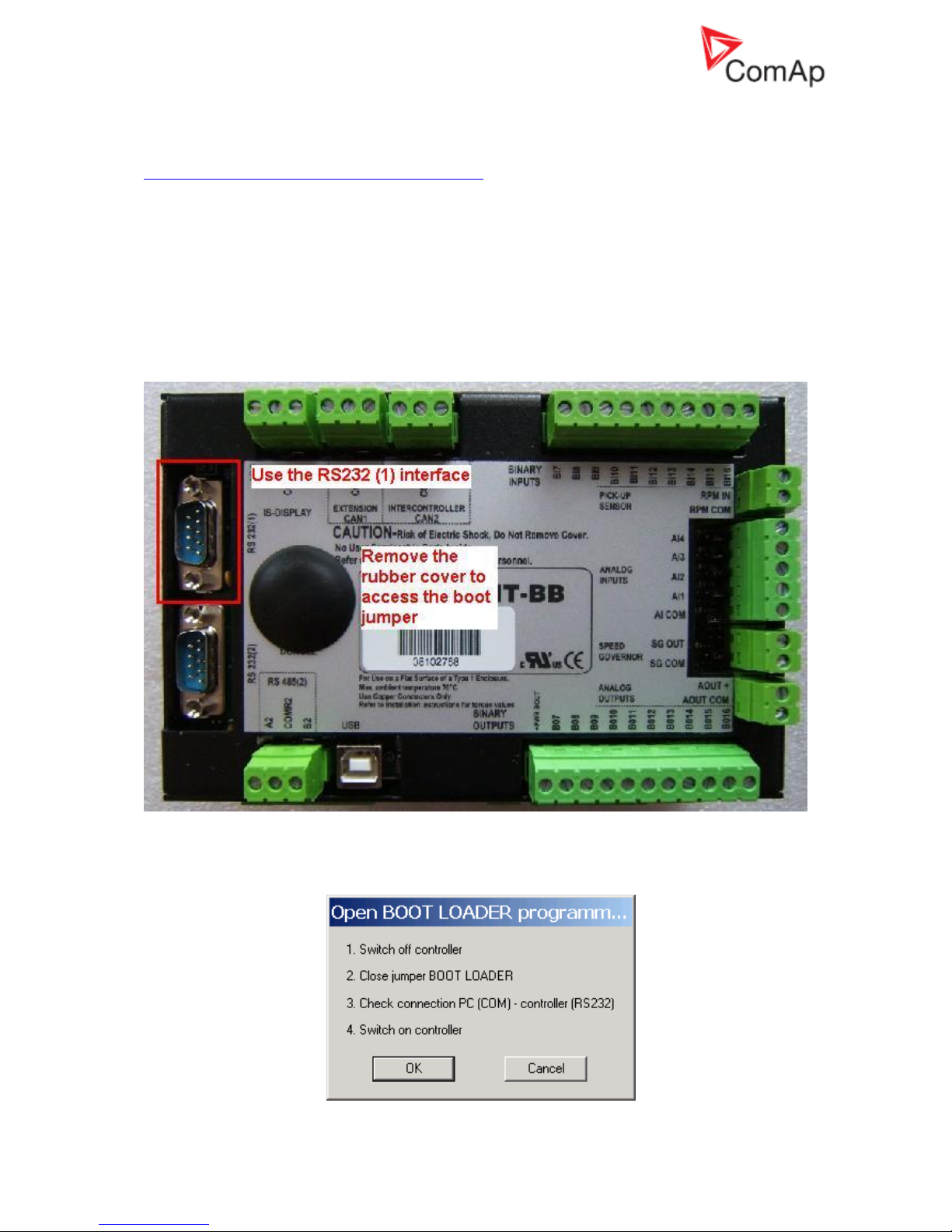
It is necessary to use the boot jumper for controller programming in case of unsuccessful controller
firmware programming. It may for instance happen due to an accidental cable disconnection,
computer failure or remote connection drop out. If controller firmware programming was not
successful, it is not possible to open connection to a controller, it does not respond and controller
screen is blank. In such case you need to use this procedure for controller programming:
1. Close connection to controller and start GenConfig
2. Check communication port setting in GenConfig. Go to Options – Select connection and select
the right communication port. It is necessary to use the RS232 (1) controller interface, boot jumper
programming does not work with the RS232 (2) or USB controller interface.
3. Go to File – Firmware upgrade and Cloning… – FW upgrade (default configuration)… and select
firmware you would like to upload into a controller.
4. Follow instructions in the notification window:
Page 8
InteliGenNT, InteliSysNT, InteliMainsNT – Troubleshooting Guide,
SW version IGS-NT-3.1.0, IM-NT-3.1.0, ©ComAp – August 2018 8
IGS-NT Troubleshooting Guide.pdf
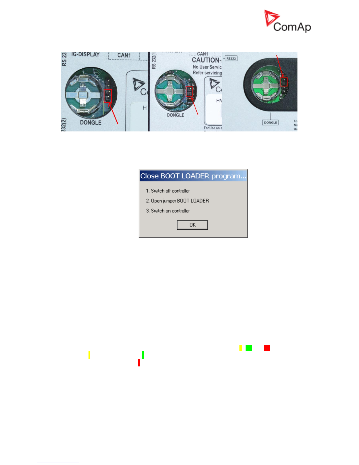
Opened BOOT LOADER jumper is marked on the picture (there are three different possibilities):
IG-NTC and IS-NT IG-NT IGS-NT(C)-BB
Close the jumper for programming.
5. Follow instructions in the notification window after programming:
It is possible to configure and program controller in the standard way after this procedure is done.
How to check that CAN communication between controllers works
Check strings CAN16 and CAN32 to see if controller communicates with other controllers via the
CAN2 bus (Intercontroller&Monitoring CAN2). Use InteliMonitor, go to Values - Info to check state of
the strings. These strings contains information about addresses of other controllers which
communicates with a particular controller. Position of each controller in the strings is given by setpoint
Comms setting: Contr. address.
Strings looks like this if you are checking strings on controller with Comms setting: Contr. address set
to 1 and controller does not communicate with any other controllers via CAN2:
CAN16 I000000000000000
CAN32 0000000000000000
Strings looks like this if you are checking strings on controller with Comms setting: Contr. address set
to 1 and controller communicates with controllers with Contr. address set to 2, 16 and 31:
CAN16 I I 0000000000000 I
CAN32 00000000000000 I 0
Strings Reg16 and Reg32 are available directly on controller screens if MINT, Combi or COX
application is used in controller. These strings contains information about addresses of controllers
which belongs into the same logical group as controller which displays this information. Strings Reg16
and Reg32 contains the similar information, however the symbol “I” is displayed only for controllers,
that belong to the same logical group as this controller.
For more information about logical groups see description of Pwr management: Control group,
GroupLinkLeft and GroupLinkRight setpoints (these setpoints are part of the ProcessControl group in
the COX application) in a relevant IGS-NT-xy-Reference Guide.
Page 9
InteliGenNT, InteliSysNT, InteliMainsNT – Troubleshooting Guide,
SW version IGS-NT-3.1.0, IM-NT-3.1.0, ©ComAp – August 2018 9
IGS-NT Troubleshooting Guide.pdf
CAN communication does not work
Problem:
CAN communication (either via CAN1 or CAN2 interface) does not work.
Solution:
a) Check if CAN bus is properly terminated. Measure resistance between the H and L CAN
terminals when all devices connected to a CAN bus are switched off. Resistance between the
H and L should be about 60 Ω, because two 120 Ω resistors has to be used to terminate CAN
bus at the both ends of a CAN line. See External modules connection chapter in IGS-NTInstallation Guide for information about CAN bus connection.
Be aware that some ComAp devices has a built in 120 Ω resistor which is connected to a CAN
bus if jumper next to a CAN interface is closed! Make sure that the terminating resistor jumper
is closed only in devices which are at the ends of a CAN line.
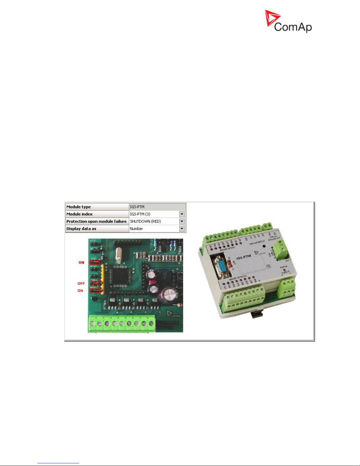
b) Check if each device connected to a CAN bus has a unique CAN address.
In case of the CAN 2 bus it means that Comms settings: Contr. address setpoint has to be
set to a unique number in each controller which is connected to the CAN2 bus. See Addresses
of Modules on CAN2 chapter in Inteli Communication Guide for information about setting of
CAN addresses in ComAp communication modules and InteliVision to avoid conflict between
addresses.
In case of devices connected to the CAN 1 bus make sure that addresses are set according to
instructions which are displayed upon module configuration on the GenConfig card Modules.
On the picture is example of information which is displayed about IGS-PTM module jumpers
setting. Similar information is displayed for all extension modules.
c) Check wiring topology of the whole CAN bus cable. The topology must be linear (straight), not
“star type” and must not contain any loops.
Page 10

InteliGenNT, InteliSysNT, InteliMainsNT – Troubleshooting Guide,
SW version IGS-NT-3.1.0, IM-NT-3.1.0, ©ComAp – August 2018 10
IGS-NT Troubleshooting Guide.pdf
Controller interface
Setpoints setting cannot be changed
Solution:
a) Setpoints are password protected and password is not entered. Go to menu ->
Users/Password and log in. If your user profile has sufficient access rights, setpoints editing
will be unblocked. System administrator can change controller configuration to give you
access to setpoints.
b) Password is entered (= user is logged in), but setpoints cannot be changed. That means these
are probably blocked by some higher protection level than the current user has got. You need
to log in as a user with sufficient access rights or contact system administrator to give you
access to setpoints.
c) Access lock function is active. Switch the Access lock function off.
Controller does not react to buttons pushing
Problem:
Controller does not react to Start, Stop, Fault & Horn reset, GCB, MCB, MGCB or controller
mode ←,→ buttons pushing.
Solution:
a) Controller is not in MAN or SEM (IS-NT only) mode, switch it to one of these modes. See
OFF-MAN-AUT-TEST mode chapter in IGS-NT-x.y-Reference Guide for information which
buttons works in a particular mode. For example GCB, MCB, Start and Stop buttons does not
work in the AUT mode.
b) There are active alarms in controller alarm list. Button function can not be performed because
of an alarm activity. Get rid of an alarm first and use a button again.
c) Setpoint Basic settings: Local buttons is set to position EXTBUTTONS, which means that
only external control using binary inputs is enabled. Set this setpoint to position PANEL or
BOTH to be able to control genset using its panel buttons.
d) Access lock function is active. Switch the Access lock function off.
Controller mode cannot be changed
Problem:
Controller mode cannot be changed,
Solution:
a) The Basic settings: ControllerMode setpoint is password protected and password is not
entered. Go to menu -> Users/Password and log in. If your user profile has sufficient access
rights, setpoint will be unblocked. System administrator can change controller configuration to
give you access to commands and setpoints.
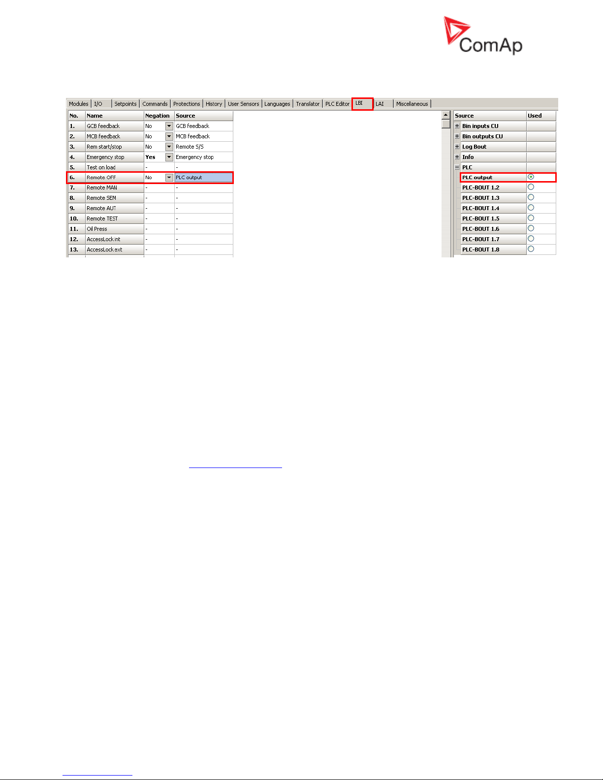
b) Function for controller mode forcing is active. Go to Measurement IO / Binary inputs and
check if binary input with Remote OFF, Remote MAN, Remote AUT or Remote TEST function
is active. If present and active (check also input polarity using GenConfig – input function can
be inverted), controller mode cannot be changed from mode selected with a binary input
function. It is necessary to change binary input state or disconnect binary inputs from
controller to be able to change controller mode. There may not be binary input with one of the
above mentioned functions.
Page 11
InteliGenNT, InteliSysNT, InteliMainsNT – Troubleshooting Guide,
SW version IGS-NT-3.1.0, IM-NT-3.1.0, ©ComAp – August 2018 11
IGS-NT Troubleshooting Guide.pdf
Check the LBI card in GenConfig to see if e.g. PLC output is used to force controller into a particular
mode:
Some setpoints cannot be changed even if correct password is used
Solution:
Force value function is probably configured to a setpoint and activated. If the function is active
(i.e. alternative value is forced), the original value is not visible and cannot be changed. To
modify the original value, deactivate the Force value function(s) related to this setpoint first.
Letter F is displayed next to a setpoint if its setting is changed using the Force value function.
You can check in GenConfig if Force value is configured to a setpoint which can not be
changed and how it is activated.
Unknown alarm is displayed
Problem:
Alarm which can not be found in this guide or a Reference Guide is displayed by controller.
Solution:
All texts which are displayed by controller can be changed using Trasnlator in GenConfig.
Try to find an alarm text on the Translator card, use the Ctrl+F function to find and alarm text
and match it with the default English text. Check PLC functions Force protect setting and
customized protections (see card Protections in GenConfig) to find alarm messages which are
not listed in the List of Possible Events.
Wrong display HW message
Problem:
“WRONG DISPLAY HW” message is displayed if wrong display hardware is detected.
Solution:
It is necessary to send IS-Display/IG-Display to ComAp for repair if the message is displayed.
Configuration table error
Problem:
“Configuration table error” message is displayed by controller. There are two possible reason:
1. Controller configuration upload was not done properly (typical reason is cable disconnection
during configuration upload)
2. Controller was set up incorrectly during production
Solution:
Try to upload your configuration into controller again. Use one of default configuration files if it
does not help (in case that the original configuration is corrupted).
In case that configuration uploads does not help, connect InteliMonitor to the controller and
check if it is in the INIT state. It is necessary to send controller to ComAp for repair if the
message is displayed and controller is in the INIT state. In case that InteliVision is used, these
two messages has the same meaning as “Configuration table error“:
Comm. error (24492:080000F7)
Timeout (24571:080000BC)
Page 12

InteliGenNT, InteliSysNT, InteliMainsNT – Troubleshooting Guide,
SW version IGS-NT-3.1.0, IM-NT-3.1.0, ©ComAp – August 2018 12
IGS-NT Troubleshooting Guide.pdf
Display is blank and LEDs are neither blinking nor glowing
Problem:
There is nothing displayed by controller, display backlight is off and LEDs are not flashing or
glowing.
Solution:
a) There is no power supply voltage. Check the power supply voltage.
b) Boot jumper is closed, switch controller off, open the jumper and switch controller on.
Display is blank, but backlight works
Problem:
There is nothing displayed by controller, but display backlight is on.
Solution:
a) Previous controller programming failed, follow instructions in the Unsuccessful controller
programming section.
b) IG-NT, IG-Display: Display contrast is set to an extremely low value. Hold Enter and push the
arrow up ↑ button then to increase contrast.
Display is showing “Unsupported code page”
Problem:
The following message is shown on the display: Unsupported code page
Solution:
The language used in the controller is not supported in the display (unsupported languages
with graphical characters). In this case, change the language of the controller and contact
ComAp to get more information about supported graphical languages (by default Chinese and
Korean).
INIT is displayed and controller mode cannot be changed
Problem:
The unit shows "INIT" and does not work, controller mode can not be changed. This situation
occurs after controller reset. Reason of the problem are either incorrectly set setpoints or flat
RTC battery.
Solution:
a) A new firmware containing new setpoints was uploaded into a controller. Use InteliMonitor
online connected to the controller to check all setpoints and fix setting of those which are set in
a wrong way. You have to change at least one setpoint setting. If all setpoints are correct,
change one of them and put it back to the original value to recalculate the checksum. It may
be necessary to switch controller off and on after changing setpoints setting. You can tick
Reset from Init state function in Options in GenConfig to avoid repeating of this problem (Init
state reset is done automatically by GenConfig if this function is active).
b) The RTC backup battery is flat. Send a controller to your distributor for battery exchange if the
RTCbatteryFlat message is displayed4.
External display problems
No reaction to pushing command buttons or setting adjustments
Problem:
It is not possible to adjust any setpoint setting and issue any command using IG-NT panel,
IG/IS-Display module or InteliVision (IV).
Solution:
Access lock input is active for that particular terminal, therefore this terminal can be used only
for monitoring. You can check this by looking on the first measurement screen (press Esc to
enter menu and select Measurement).
These symbols are displayed if access lock is active:
IS-Display – “crossed hand” symbol is displayed in the upper left corner
IG-Display and IG-NT – lock symbol is displayed in the upper right corner
InteliVision – “crossed hand” symbol is displayed in the upper right corner of the Status bar
Page 13
InteliGenNT, InteliSysNT, InteliMainsNT – Troubleshooting Guide,
SW version IGS-NT-3.1.0, IM-NT-3.1.0, ©ComAp – August 2018 13
IGS-NT Troubleshooting Guide.pdf
part of measurement screens (see Operator Interface chapter in an InteliVision
Reference Guide for information about the Status bar part of measurement
screens)
Binary input
function
Locked display module
AccessLock int
IG-NT/EE internal display, IS-Display and IV with Terminal address = 1
AccessLock D#2
IG-Display, IS-Display and IV with Terminal address = 2
AccessLock D#3
IS-Display and IV with Terminal address = 3
InteliVision/InteliVision 8 and image retention
Problem:
In general LCD screens are susceptible to image retention at varying degrees. Image
retention is caused by a parasitic capacitance build up within the LCD cell, which prevents the
liquid crystal molecules from returning to their normal relaxed state.
Image retention (reversing burn-in) can be observed during using InteliVision, when retention
of the main screen, which is displayed for most of the time, is strongly visible also on other
screens. This image retention is not permanent change. After some time it fades.
Solution:
DECREESE BRIGHTNESS of screen to approx. 50-60%.
This solution helps to decrease recovery time of a screen to less than 2 minutes, when an
image retention fades (the time can be longer if is used IV in too hot or too cold environment).
There are two brightness settings available:
• Day mode
• Night mode (especially for Marine applications)
Changing the modes can be done by holding the ESC button for 1 second.
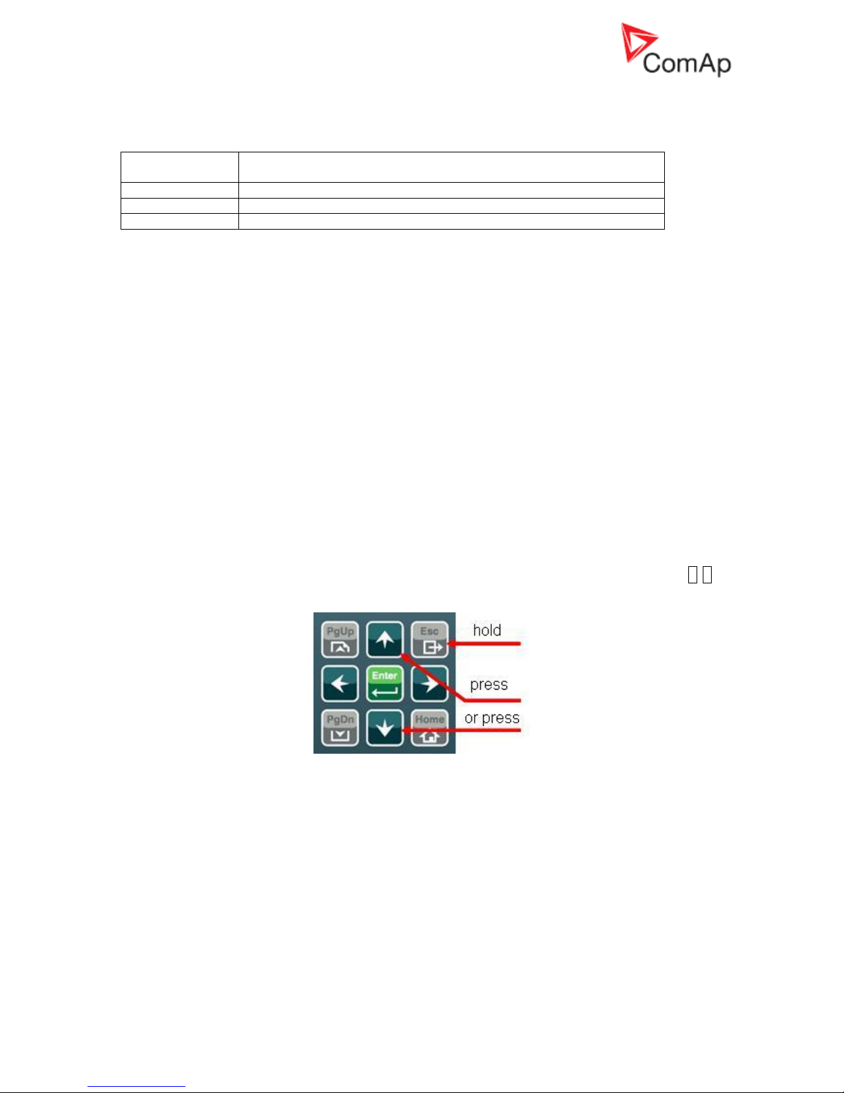
Display brightness can be adjusted in range from 0 % to 100 % in both modes. Brightness of
the display can be increased/decreased by holding Esc button and repeated pushing .
See the picture below:
Push ESC + PgUp buttons or ESC + PgDn buttons to select mode which should be adjusted.
Page 14

InteliGenNT, InteliSysNT, InteliMainsNT – Troubleshooting Guide,
SW version IGS-NT-3.1.0, IM-NT-3.1.0, ©ComAp – August 2018 14
IGS-NT Troubleshooting Guide.pdf
Synchronizing, Load control
Gen-set voltage is increasing/decreasing over/under the limits during
synchronization
Problem:
When gen-set is synchronizing to the Bus/Mains its voltage goes out of limits and GCB is
opened due to over/undervoltage protection.
Solution:
a) Check setpoints GenNomV or GenNomVph-ph if they are adjusted to proper value.
b) If the voltage is adjusted properly check if the same value is in MainsNomV/BusNomV or
MainsNomVph-ph/BusNomVph-ph. These values need to be adjusted to the same value
even if nominal voltages of gen-set and Bus/Mains are different!
c) See the example below for proper adjustment of system with different nominal voltages on
Mains/Bus and gen-set.
Example:
Both setpoints GenNomV or GenNomVph-ph and MainsNomV/BusNomV or MainsNomVph-
ph/BusNomVph-ph must be adjusted to the same values according to the value of actual
generator nominal voltage. E.g. gen-set nominal is 231 V but Bus/Mains nominal is 240 V.
- In this case both setpoints need to be adjusted to 231 V and setpoints of corresponding
protections for Bus/Mains need to be set assymetrically.
- For 240 V on Bus/Mains it is typical to open MCB when voltage reaches 254 V or 225 V.
- Since the setpoint for Mains/Bus nominal voltage is adjusted to 231 V corresponding
protection setpoints need to be adjusted to Mains >V/Bus >V = 106% and Mains <V/Bus
<V = 97 % (hence the desired values are reached).
GCB is opened before the Load ramp time is over
Problem:
After reverse synchronization and during generator unloading is GCB opened before the Load
ramp time is over.
Solution:
a) AMF settings: BreakerOverlap time is shorter than the Sync/Load ctrl: Load ramp time
setting. Set Breaker overlap to the same or longer time than Load ramp setpoint.
b) GCB is opened during generator unloading as soon as generator power level given by
setpoint Sync/Load ctrl: GCB open level is reached. Decrease the GCB open level setting to
avoid premature GCB opening.
c) Load in island was much lower than gen-set nominal power. The real time of load ramp is
Load ramp x Pinitial_island / Nomin power; controller switches off GCB immediately (with 1s
delay) as soon as generator power gets below the GCB open level.
Sync fail alarm is issued
Solution:
a) Setpoint Sync/Load ctrl: Sync timeout is set to too short time -> set it to a longer time to allow
controller to match all synchronizing conditions.
b) Speed governor or AVR control is not setup correctly. See chapters Speed Governor Interface
List and AVR Interface List in IGS-NT Installation Guide for information about proper
connection of a speed governor and AVR. See Sync/load control adjustment and Volt/PF
control adjustment chapters in an IGS-NT Reference Guide for information how to setup
controller speed and voltage regulation loops correctly.
MGCB is not closed even all conditions are fulfilled
Solution:
a) IM-NT Bus protect: Bus >V Hst, Bus <V Hst, Bus >f, Bus <f do not have the same settings as
IG/IS-NT generator control unit (use the same settings for generator and mains control unit).
b) IM-NT and other gen-sets are not in the same logical group. See setpoints Pwr Management:
Control group (Controller cannot see each other via CAN bus).
Page 15

InteliGenNT, InteliSysNT, InteliMainsNT – Troubleshooting Guide,
SW version IGS-NT-3.1.0, IM-NT-3.1.0, ©ComAp – August 2018 15
IGS-NT Troubleshooting Guide.pdf
IM-NT BTB connects dead buses together
Problem:
It happens, because even dead buses are evaluated by controller as “healthy”. Reason is
that either setpoints BusL protect: BusL Volt prot and BusLfreq prot are set to DISABLED or
setpoints BusR protect: BusR Volt prot and BusRfreq prot are set to DISABLED. These
settings means that controller does not evaluate if bus is healthy according to bus voltage and
frequency protections setpoints setting, because bus voltage and frequency check are simply
disabled.
Solution:
Change setting of at least one above mentioned setpoint (BusxVolt prot and/or Busxfreq prot)
to ENABLED (in both BusL protect and BusR protect groups) to avoid connecting of dead
buses.
Power management
Gen-set doesn't share load with other gen-sets
Solution:
Check if the gen-set is not running in the local baseload mode. This mode is active if setpoint
ProcessControl:LocalBaseload is set to other value than OFF. If this setpoint is not set to
OFF then the gen-set is taken out of Load sharing and Power management. Fof rmore details
see chapter Local Baseload in IGS-NT-MINT-x.y-Reference Guide.
Running Hours Equalization does not work properly
Problem:
Gensets priority switching based on engine running hours (Pwr management: PriorAutoSwap
is set to RUN HOURS EQU) does not work properly and some or all gensets has the same
priority. It means that gensets with the same priority behaves as one large genset and runs at
the same time.
Solution:
This problem is caused by incorrect priority switching system initialization. Follow these steps
to get rid of the problem:
1. Set #PriorAutoSwap setpoint to DISABLED
2. Set Priority setpoints in all controllers to unique numbers
3. Set #PriorAutoSwap setpoint to RUN HOURS EQU
Load shedding is active although not all gensets are loaded
Problem:
Load shedding outputs (LdShed stage 1,2 and 3) are active although not all available gensets
are loaded (running and connected to bus). The reason is that Load shedding and Power
management control systems are independent and it is necessary to set controller properly to
avoid this situation.
Solution:
Use controller power management in “relative” mode. It means that Pwr management: #Pwr
mgmt mode has to be set to REL (%). Make sure that Pwr management: #%LdResStrt x is
set below Load shedding: Ld shed level so idle genset is started before load shedding output
is activated.
Page 16
InteliGenNT, InteliSysNT, InteliMainsNT – Troubleshooting Guide,
SW version IGS-NT-3.1.0, IM-NT-3.1.0, ©ComAp – August 2018 16
IGS-NT Troubleshooting Guide.pdf
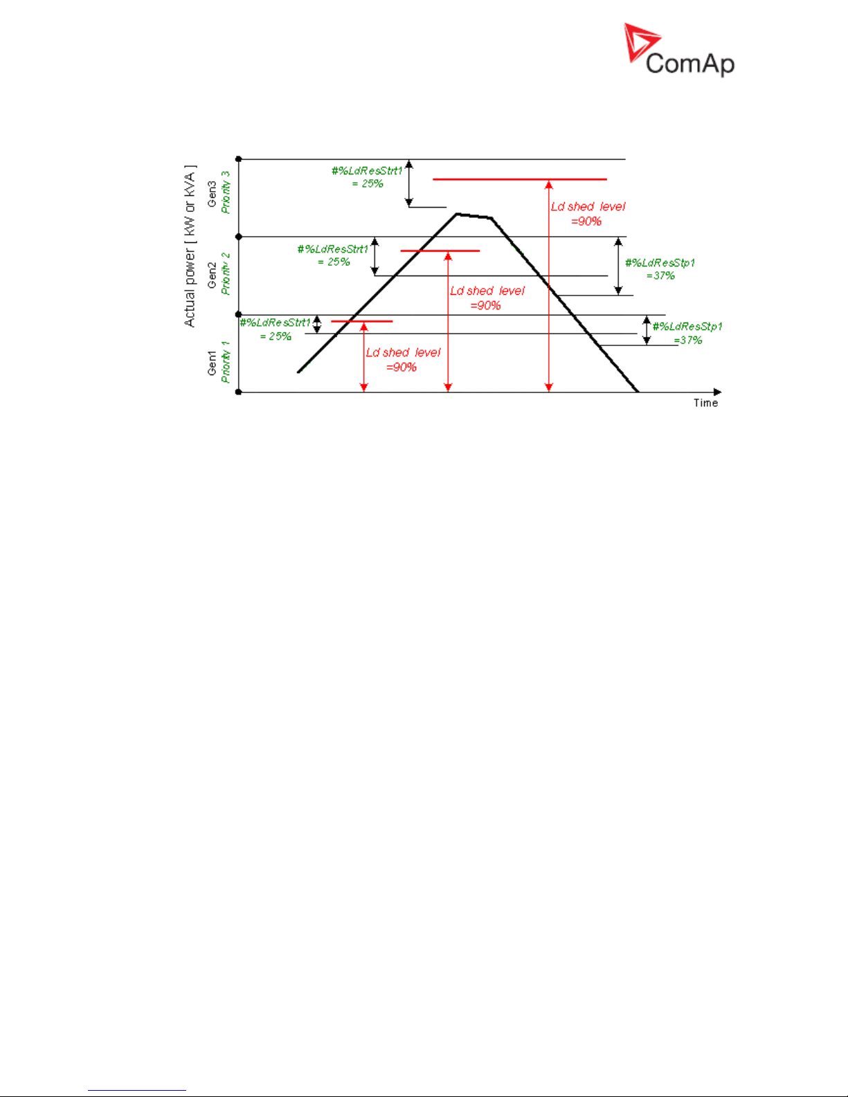
Example of correct Power management and Load shedding setting is on this
picture:
You can see that the Pwr management: #%LdResStrt1 limit is crossed first when system load
goes up and request to start additional genset is issued before the load shedding request.
However, it is not enough to set limits in the suggested way to make system work properly. It
is important to set Pwr management: #NextStrt del much shorter than Load shedding: Ld
shed delay so there is enough time for starting genset to start, synchronise and take over load
before a load shedding output is activated.
MGCB is not closed although gensets are running
Problem:
All available gensets are running and connected to bus (GCB’s are closed), but IM-NT does
not close MGCB.
Reason of the problem is that Act Reserve (Actual load reserve) value is not higher than value
of currently used Pwr management: LoadResStrt x setpoint (binary input functions Load res
x can be used for switching between LoadResStrt x setpoints). Act Reserve has to exceed a
LoadResStrt x value so IM-NT evaluates system reserve as sufficient to connect load to
gensets (this evaluation is not done when system should run in parallel with mains).
Check state of the Syst res OK signal in InteliMonitor (go to Values/Log Bout/LogBout 4) to
see if Act Reserve is evaluated by IM-NT as sufficient enough (condition for MGCB closing is
ActReserve > LoadResStrt x)
Solution:
a) Check if setpoint Pwr management: Pwr management is set to ENABLED in genset
controllers (there is no such setpoint in IM-NT itself). Act Reserve value (P
BNom
) in IM-NT is
based on information it receives from gensets power management system. There is no
information about available power sent from gensets controllers to IM-NT if Pwr management
is set to DISABLED.
b) Decrease value of a currently used Pwr management: #LoadResStrt x setpoint so available
Act Reserve (P
BNom
) is higher than the #LoadResStrt x setpoint. Do that if you consider
available Act Reserve power sufficient enough to cover a system load.
You can use alternative #LoadResStrt x setpoint with setting low enough to enable MGCB
closing (use a Load res x binary input function for switching to a different LoadResStrt x
setpoint).
c) Set Pwr management: #LoadResStrt x setpoint to a negative value if you can not set Pwr
management: Pwr management setpoint to ENABLED in gensets controllers (e.g. IGS-NT-
LSM+PMS dongle is not used in genset controllers and power management function is not
available then). It is necessary to fulfill the following condition to enable MGCB closing:
P
BNom
> P
Akt
+ Reserve
P
BNom
Sum of the nominal power of all running gen-sets (displayed as Act Reserve
value by IM-NT)
Page 17

InteliGenNT, InteliSysNT, InteliMainsNT – Troubleshooting Guide,
SW version IGS-NT-3.1.0, IM-NT-3.1.0, ©ComAp – August 2018 17
IGS-NT Troubleshooting Guide.pdf
P
Akt
System load
Reserve selected setpoint #LoadResStrt x
Setting setpoint Pwr management to DISABLED in genset controllers means that P
BNom
is
always 0 in IM-NT (no power information is received from genset controllers) and it is
necessary to set #LoadResStrt x to a negative value to meet the condition for MGCB closing.
It is sufficient to set #LoadResStrt x to -1 if only one MGCB needs to be closed (P
Akt
is always
0 before the first MGCB breaker is closed). However, this setting is not sufficient if several
MGCBs should be closed and it is necessary to set #LoadResStrt x to a lower value.
E.g. it is necessary to set a #LoadResStrt x setpoint to -101 (or a lower value) to achieve
second MGCB closing if P
Akt
is 100 after closing of the first MGCB:
P
BNom
> P
Akt
+ Reserve
0 > 100 + (-101)
PC software
There is no history in .ant file
Solution:
a) InteliMonitor / Settings / History – the Typical program setting is to “Site monitored from this
computer only”. If this is not true, i.e. some other computer may be connected sometimes to
the site (controller), it may read out the history records and after this computer is connected
again, there appear to be no records in the archive. In such a case (especially can happen
with remote, e.g. modem connections), please switch to “Site monitored from more
computers”, which ensures proper history reading. The first option provides faster history
reading if there are only few new records, but with more computers accessing the same site
leads to the above mentioned behaviour.
b) Archive was saved with GenConfig tool with version lower than 2.1. GenConfig is offline tool
for configuration purposes, so archives saved using this tool does not contain actual history
data. That’s why history is not saved at all with this tool. Starting from version 2.1, GenConfig
is able to read history from controller and save it as part of controller configuration file.
History is not complete
Problem:
Some history records which are available in controller are not included in downloaded history.
Solution:
This problem is caused by InteliMonitor setting. It happens if history reading is set to Site
monitored from this computer only and more computers are used to read data from a
controller. InteliMonitor with Site monitored from this computer only setting reads only history
records which were not downloaded during the last connection and records are missing if the
last connection was done using a different computer.
Go to Settings -> History and change setting from Site monitored from this computer only to
setting which matches your needs. Recommended settings are Site monitored from more
computers or Service tool (see InteliMonitor-x.y-Reference Guide manual for more
information).
Electrical measurement
Controller measures wrong generator/mains/bus voltages or currents
Problem:
Controller measures wrong generator/mains/bus voltages or currents, because setpoint Basic
settings: CT ratio prim / Im3ErFlCurCTp / VT ratio / Vm VT ratio is set to a wrong value.
Setpoint setting does not match CT / VT ratio of used measurement transformer.
Solution:
a) Change it to correct value according to the VT/CT specification.
Page 18

InteliGenNT, InteliSysNT, InteliMainsNT – Troubleshooting Guide,
SW version IGS-NT-3.1.0, IM-NT-3.1.0, ©ComAp – August 2018 18
IGS-NT Troubleshooting Guide.pdf
b) For IS-NT-BB or IG-xxC HW types, setpoint Basic settings: CT ratio sec / Im3ErFlCurCTs /
VgInpRangeSel / VmInpRangeSel is set to a wrong secondary voltage/current range. Set it to
correct range (5A or 1A, 120V or 277V).
Power measurement does not work
Problem:
It may happen that controller measures correct generator/mains/bus voltages and currents
values, but active and reactive power values displayed by controller are not correct or even
zero. Power Factor (PF) value is incorrect too and there is a big difference in PF between
phases (e.g. phase L1 power factor is 0,9 and in phase L2 power factor is 0,2).
Solution:
Solution is to adjust CTs connection, it means changing polarity of CTs and/or swapping their
order.
Correct voltage and current measurement connection:
Imagine that a generator is loaded with a load bank which burns 100 kW in each phase. Load
bank Power Factor (PF) is 1. If power in each phase is 100 kW, total generator power (P
TOT
)
displayed by controller is 300 kW. Calculation is as follows:
UL1=UL2=UL3= 400 V
IL1=IL2=IL3= 250 A
PFL1=PFL2=PF
L3
= 1
PL1=PL2=PL3= UL1xIL1xPFL1=400x250x1= 100 kW
P
TOT=PL1+PL2+PL3
= 100+100+100= 300 kW
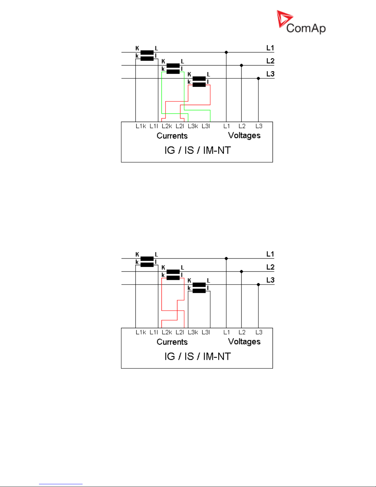
Example of incorrect connection with CTs swapped between phases L2 and L3:
Page 19
InteliGenNT, InteliSysNT, InteliMainsNT – Troubleshooting Guide,
SW version IGS-NT-3.1.0, IM-NT-3.1.0, ©ComAp – August 2018 19
IGS-NT Troubleshooting Guide.pdf
In this case 100 kW is still burned in each load bank phase, but PF in phases L2 and L3 is not
1 from controller point of view. PF in phases L2 and L3 is -0,5 due to phase shift between
voltages and currents which is caused by CTs swapping. The result is that total generator
power displayed by controller is 0 kW. Calculation is as follows:
UL1=UL2=UL3= 400 V
IL1=IL2=IL3= 250 A
PFL1=1
PFL2=PFL3= -0,5
PL1= UL1xIL1xPFL1=400x250x1= 100 kW
PL2=PL3=UL2xIL2xPFL2= -50 kW
P
TOT=PL1+PL2+PL3
= 100+(-50)+(-50)= 0 kW
Example of incorrect connection with wrong CT polarity in phase L2:
In this case 100 kW is still burned in each load bank phase, but PF in phase L2 is not 1 from
controller point of view. PF in phase L2 is -1, because current goes in the opposite way due to
wrong CT polarity. The result is that total generator power displayed by controller is 100 kW.
Calculation is as follows:
UL1=UL2=UL3= 400 V
IL1=IL2=IL3= 250 A
PFL1=PFL3=1
PFL2= -1
PL1=PL3= UL1xIL1xPFL1=400x250x1= 100 kW
PL2=UL2xIL2xPFL2= 400x250x(-1)= -100 kW
Page 20

InteliGenNT, InteliSysNT, InteliMainsNT – Troubleshooting Guide,
SW version IGS-NT-3.1.0, IM-NT-3.1.0, ©ComAp – August 2018 20
IGS-NT Troubleshooting Guide.pdf
P
TOT=PL1+PL2+PL3
= 100+(-100)+100= 100 kW
Many different combinations of incorrect CTs connection are possible so check both, order of
CTs and their polarity. Reactive power measurement is affected by incorrect CTs connection
in similar way as active power measurement.
Other
SummerTime Mode causing time rollback and time desynchronization
Problem:
Situation: multiple controllers are used on CAN bus and some of them have FW 2.6.3 (IGSNT-Std) or 2.9.1 (IM-NT) and others have older versions of FW. SummerTime Mode is active
(i.e. it is not set to DISABLE). Controllers are not powered and time change is about to be
done.
Example:
One controller with IGS-NT-Std FW 2.6.3 and one controller with IGS-NT-Std FW 2.6.1 are
connected via CAN. Date is 27.10. 2013 and time is 2:59 am. SummerTime Mode is set to
SUMMER (i.e. time change is active). Controllers are powered down and stay powered down
for period longer than one hour (e.g. 8 hours). When powered back on time and SummerTime
Mode changes rapidly causing bad time value and moreover causing desynchronization of the
time between controllers (e.g. IGS-NT-Std 2.6.3 shows 2:05 am and IGS-NT-Std 2.6.1 shows
7:05 pm).
Solution:
All controllers FW need to be updated to the latest version to prevent this behavior. When all
controllers are updated, SummerTime Mode works properly.
Note:
Note that this behavior occurs only when old and new versions are mixed. When only old
versions are present and controllers are powered down, time change does not occur (due to
previous error fixed in 2.6.3/2.9.1) but time is not desynchronized.
Wrn addr error occurs when updating to new FW
Problem:
Wrn addr error is issued. Controller address cannot be changed. (This may occur after
changing CANnegotiation setpoint to AUT and restarting the controller or after update to the
new FW version (e.g. IM-NT 2.9 to IM-NT 2.9.1) – the update may activate CANnegotiation.)
Solution:
This particular problem (Wrn addr) is caused by the function CANnegotiation and occurs only
if there are controllers with the same CAN address and without CANnegotiation ability. This
occurs only in specific case with specific hardware.
It is essential to check setpoints and write correct value in them. In this particular case please
locate the setpoint CANnegotiation (in Comms settings) and change its state (there may be
AUT or a number after update) to OFF mode. Then power down and power up the
controller. The warning should not be displayed anymore.
Note:
Function CANnegotiation can be activated only when all controllers are able to perform this
function. If there are controllers with and without CANnegotiation (e.g. IM-NT and IG-MINT),
CANnegotiation must be switch OFF in all CANnegotiation capable controllers!
Statistic values window contains strange numbers upon start-up
Problem:
All NT controllers produced till March, 2007 (serial numbers 0703xxxx and lower) have
undefined values in statistics. Controllers produced later have all statistics values set to initial
value 0.
Solution:
Should you come across a controller with undefined statistic values, run InteliMonitor, go to
menu Monitor, select Set statistics, and click on button “Clear all”. Wait until all numbers lose
their bold form (writing in process) and close the window.
Page 21

InteliGenNT, InteliSysNT, InteliMainsNT – Troubleshooting Guide,
SW version IGS-NT-3.1.0, IM-NT-3.1.0, ©ComAp – August 2018 21
IGS-NT Troubleshooting Guide.pdf
Alarms stays in Alarm list even though Fault reset was used to
acknowledge them
Problem:
Fault reset was used to acknowledge active alarms displayed by controller, but alarms stayed
in alarm list after they became inactive, because controller does not allow an alarm to be
acknowledged by pressing the fault reset button while the alarm is still active. It is caused by
setpoint Engine protect: ResetActAlarms setting to DISABLED. This is a new option which
was not available in IG/IS classic – you can now disable resetting of alarms that are currently
active by setting the setpoint to DISABLED (Marine authorities requirement).
Solution:
If you don’t need this functionality, switch the setpoint to ENABLED, which is the mode
compatible with IG/IS classic controllers.
No active call after some protection has been activated
Solution:
a) Setpoint that enables active calls for a particular protection type is not set to ENABLED.
Check it in Act. calls/SMS setpoints group.
b) Setpoint Act. calls/SMS: AcallCHx-Type is set to a wrong option. E.g. it is set to SMS-GSM,
while analog modem is actually connected. You have to change this setpoint to such option
that matches used type of connection.
c) Phone number or e-mail address is wrong. Check the setting (Act. calls/SMS: AcallCHx-Addr
setpoints), including the prefix codes for local phone calls or intercity calls.
Forgotten controller password
Solution:
a) For all users, except the user 0 = administrator, password can be reset by the administrator. If
administrator is logged in, he can set password to any value for a particular user. Controller
panel or PC can be used to do that:
Controller panel: log in as administrator (default user name of the administrator is U0), go to
Users/Password in the menu and select user for which you intend to reset the password. You
will see “Reset password” option on the screen, select it, press Enter to confirm your choice
and press Esc to get back into the menu. Now that user has password set to “0” and it can be
set to any value.
PC SW (InteliMonitor): log in as administrator (default user name of the administrator is U0),
go to menu Monitor / Admin users. A window opens where you can set up access rights etc.
Select the user for which you intend to reset its password and press the crossed lock icon in
the upper left corner. You can also reset passwords for all users at once. Password is set to
“0” and it can be set to any value.
b) If the highest (level 7) administrator password is lost, you need to provide your distributor this
information: controller serial number and PasswordDecode number.
Serial number and PasswordDecode number are available in InteliMonitor in Monitor /
Controller/Archive info... Both serial number and PasswordDecode number are available on
controller Info screen 2. Hold Enter and push the Esc button to enter the screen on IS-Display,
push the right arrow then to display information on IG-NT / IM-NT screen.
PID regulator doesn't work in the same way as in IS-CU
Solution:
a) If the PID regulator in internal PLC of the controller doesn't behave in the same as you were
used to with the classic IS-CU controller, set the parameters 10 times higher than for the PID
regulator in classic IS-CU.
MCB fail / GCB fail alarm is issued after switching controller on
Problem:
Breaker fail alarm is issued if a breaker feedback signal is not connected directly to a
controller and controller receives information about breaker state after initial reading of its
binary inputs. This happens if breaker feedback is evaluated in controller PLC or it is
connected to controller via an extension module (standard or virtual).
Page 22

InteliGenNT, InteliSysNT, InteliMainsNT – Troubleshooting Guide,
SW version IGS-NT-3.1.0, IM-NT-3.1.0, ©ComAp – August 2018 22
IGS-NT Troubleshooting Guide.pdf
Solution:
a) Connect breaker feedback signals directly to a controller binary input. Feedback signal is
delayed if it is connected to an extension unit, using a virtual periphery or it is output of
controller PLC logic. States of binary inputs are evaluated immediately after switching
controller on. It takes some additional time to run PLC or establish remote communication via
CAN (virtual periphery-SHBIN) or with a standard extension module (e.g. IGS-PTM). Breaker
feedback is very important signal for correct controller function and it is strongly recommended
to connect it directly to binary input of a controller itself.
b) Check if either breaker control signal logic (e.g. GCB close/open signal) or breaker feedback
signal logic (e.g. GCB feedback signal) is set correctly (BI/BO option Inverted is set correctly).
Page 23
InteliGenNT, InteliSysNT, InteliMainsNT – Troubleshooting Guide,
SW version IGS-NT-3.1.0, IM-NT-3.1.0, ©ComAp – August 2018 23
IGS-NT Troubleshooting Guide.pdf
How to …
Special applications
Setup your controller to work as the SSB application
SSB application is known from IG/IS classic controllers, but it is no more present among NT
applications. So you have to modify behaviour of the SPtM application to achieve that. This type of
application can be handled with IL-NT AMF controllers.
Start with the default SPtM archive and set the following setpoints in the ProcessControl group of
setpoint:
• Island enable = YES (stand-by application needs to work in island when mains is gone)
• ParallelEnable = NO (no mains paralleling is allowed)
• SynchroEnable = NONE (no synchronizing is allowed)
• MFStart enable = YES (basic function of the SSB application – start upon mains failure)
Setup your controller to work as the SPM application
SPM application is known from IG/IS classic controllers, but it is no more present among NT
applications. So you have to modify behaviour of the MINT application to achieve that. This type of
application can be handled with IL-NT MRS controllers.
Start with the default MINT archive and follow these instructions:
• The controller with MINT, COX or Combi in MINT archive can work without Dongle LSM+PMS
if all following conditions are fulfilled
o The power management must be disabled (Pwr management = DISABLED) and
o (SysLdCtrl PtM must be swithed to BASE LOAD and MCB feedback must be 1) or there
is no CAN2 communication
The conditions above allow user to use the following combinations without Dongle:
Pwr
management
SysLdCtrl PtM
MCB feedback
CAN2
communication
DISABLED
BASE LOAD
1
YES
DISABLED
ANY
ANY
NO
If the above conditions are fulfilled, there is no “Dongle incomp” message displayed in
controller Alarm list. This message is normally displayed by controller with MINT application as
the IGS-NT-LSM+PMS dongle is expected to be used for standard use of the MINT
application. In this special case and providing the stated conditions, the message is
suppressed to allow controller to work in the SPM mode.
Page 24

InteliGenNT, InteliSysNT, InteliMainsNT – Troubleshooting Guide,
SW version IGS-NT-3.1.0, IM-NT-3.1.0, ©ComAp – August 2018 24
IGS-NT Troubleshooting Guide.pdf
List of Abbreviations
AMF
Auto Mains Failure (controller starts automatically on mains failure)
AI
Analog Input
AO
Analog Output
ATS
Automatic Transfer Switch (switches load to supplied bus (by mains or generators))
AVR
Automatic Voltage Regulator
BI
Binary Input
BO
Binary Output
BOC
Breaker Open & Cool-down - protection type (see application manual for details)
BTB
Bus-Tie Breaker
CAN1
CAN bus for ComAp extension modules (e.g. IGS-PTM) and engine ECU
connection
CAN2
CAN bus for communication between ComAp controllers and communication
modules connection (e.g. I-LB+)
COX
Application for Complex Systems where actions are taken by a PLC and controller
only follows orders => needs an external driver (cox)
CT
Current Transformer
ECU
engine Electronic Control Unit
ESF
Engine Specific File
Forward synchronisation
Synchronisation of unloaded genset to mains (GCB closing process)
FMI
Failure Mode Identifier
GC
Graphical Characters - option for additional support of one "graphical" language
GCB
Generator Circuit Breaker
CHP
Combined Heat & Power - cogeneration application, usually with gas engine
I-AOUT8
Extension module with 8 AO
I-CB
Communication Bridge - interfaces IS, IG/IS-NT, ID controllers and non-standard
engine ECU
IG-AVRi
IG Automatic Voltage Regulator interface
IG-EE
InteliGen for Electronic Engines (HW optimized for connection to an engine
equipped with ECU)
IG-EEC
InteliGen EE controller with extended communication possibilities + switchable
sensing ranges of AC voltages and currents
IG-IB
IG-Internet Bridge - for internet/ethernet communication
IGL-RA15
Indication panel with LEDs signalizing state of 15 BO
IG-NT
InteliGen New Technology gen-set controller
IG-NTC
InteliGen NT controller with extended communication possibilities + switchable
sensing ranges of AC voltages and currents
IGS-NT-LSM+PMS
Dongle for IG-XX and IS-NT to enable Load Sharing and VAr sharing control loops
and PMS
IGS-PTM
Extension module with 8 BI/BO, 4 AI and 1 AO
I-LB
Local Bridge – for direct and modem monitoring and control of multiple gen-sets
IM-NT
InteliMains New Technology - Mains supervision controller; the same controller with
a different SW configuration can work as a bus-tie synchronizer
I-RB
Relay Board
IS-AIN8
Extension module with 8 AI.
IS-BIN8/16
Extension module with 8 BO and 16 BI.
Page 25

InteliGenNT, InteliSysNT, InteliMainsNT – Troubleshooting Guide,
SW version IGS-NT-3.1.0, IM-NT-3.1.0, ©ComAp – August 2018 25
IGS-NT Troubleshooting Guide.pdf
IS-NT
InteliSys New technology gen-set controller
IS-NT-BB
InteliSys New Technology Basic Box (without display)
KWP2000
Key Word Protocol of Scania S6 unit (for engine diagnostics)
LAI
Logical Analog Inputs (card in GenConfig which is used to assign source signal to
controller Logical Analog Input functions, e.g. Oil press)
LBI
Logical Binary Inputs (card in GenConfig which is used to assign source signal to
controller Logical Binary Input functions, e.g. Sys Start/Stop)
LS
Load Sharing - analog load sharing line to interconnect gen-sets on site (for island
parallel or mains parallel operation of multiple gen-sets); IG/IS/IM-NT controllers
use digital Load Sharing via the CAN2 bus
LSM
Load Sharing Module
LT
Option for Low Temperature modification (display equipped with heating foil)
MCB
Mains Circuit Breaker
MGCB
Master Generator Circuit Breaker (sometimes used with multiple gen-sets in island
parallel or mains parallel operation)
MINT
Multiple application with INTernal control loops - for multiple gen-sets in island
parallel or mains parallel operation; Load Sharing and VAr Sharing controlled
internally; PMS available
MP
Mains protection
MultIslOp
Multiple Island Operation (MCB is opened, GCB’s are closed)
MultParOp
Multiple Parallel Operation (MCB is closed, GCB’s are closed)
NPU
Mains protection relay (voltage, frequency, vector shift protections)
OC
Occurrence Count (number of fault occurrances transmitted in diagnostic frame
from ECU)
OfL
Off load - protection type (see application manual for details)
PF
Power Factor
PGN
Parameter Group Number (refer to SAE J1939-71)
PMS
Power Management System - ensures optimization of running gen-sets on sites
with multiple gen-sets; based on kW/kVA spinning reserve or on relative (%) load;
no-master system ensures high reliability
Reverse synchronisation
Synchronisation of loaded genset to mains (MCB closing process)
RTC
Real Time Clock
SG
Speed Governor
SHAIN
Shared (virtual) Analog INput module
SHAOUT
Shared (virtual) Analog OUTput module
SHBIN
SHared (virtual) Binary INput module
SHBOUT
SHared (virtual) Binary OUTput module
Soft load
Generator soft loading according to Load ramp loop setting
Soft unload
Generator soft unloading according to Load ramp loop setting
SPI
Single Parallel Island application - for single gen-sets in parallel with mains or in
island operation; suitable for CHP applications; no MCB control
SPM
Single Prime Mover application - for single gen-sets without mains
SPN
Suspect Parameter Number (refer to SAE J1939-71)
SPtM
Single Parallel to Mains application - for single gen-sets in parallel with mains or in
island operation, with AMF support; both MCB and GCB controlled
SSB
Single Stand-By application - for single gen-sets with mains and break transfer to
mains
VPIO
Virtual periphery I/O module – internal “SW wires” linking binary outputs to inputs
VS
VAr Sharing - ensures VAr sharing between gen-sets on site via the CAN2 bus (for
island parallel or mains parallel operation of multiple gen-sets)
VT
Voltage Transformer
#
Setting of setpoints (with this character in front of them) is shared between
Page 26

InteliGenNT, InteliSysNT, InteliMainsNT – Troubleshooting Guide,
SW version IGS-NT-3.1.0, IM-NT-3.1.0, ©ComAp – August 2018 26
IGS-NT Troubleshooting Guide.pdf
controllers via intercontroller CAN2
Page 27

InteliGenNT, InteliSysNT, InteliMainsNT – Troubleshooting Guide,
SW version IGS-NT-3.1.0, IM-NT-3.1.0, ©ComAp – August 2018 27
IGS-NT Troubleshooting Guide.pdf
List of Possible Events
Hint:
Be aware that it is possible to change alarm messages using Translator in GenConfig. Try to find an
alarm text in the Trasnlator card if you can not find it on this list. Use Ctrl+F function to find an alarm
text.
Check PLC functions Force protect setting and customized protections (see card Protections in
GenConfig) to find alarm messages which are not listed below.
IGS-NT Alarm/History
record
Alarm/
History
Appeara
nce
Description
BIN 1-12
1
A+H
Indication of error in communication with binary inputs
extension module.
Check if the unit with corresponding CAN address is
- powered up
- address of the module is set correctly (see
Modules card in GenConfig and an extension
module manual)
- correctly connected and check connection of
terminating resistors on the CAN1 bus (see IGSNT Installation Guide, External modules
connection chapter)
- the CAN bus Low and High wires are not swapped
To check module communication activity look at the Tx
and Rx LEDs of the CAN bus port. Fast flashing means
that communication is OK.
ANA 1-101
A+H
Indication of error in communication with analog inputs
extension module.
Check if the unit with corresponding CAN address is
- powered up
- address of the module is set correctly (see
Modules card in GenConfig and an extension
module manual)
- correctly connected and check connection of
terminating resistors on the CAN1 bus (see IGSNT Installation Guide, External modules
connection chapter)
- the CAN bus Low and High wires are not swapped
To check module communication activity look at the Tx and
Rx LEDs of the CAN bus port. Fast flashing means that
communication is OK.
BOUT 1-121
A+H
Indication of error in communication with binary outputs
extension module.
Check if the unit with corresponding CAN address is
- powered up
- address of the module is set correctly (see
Modules card in GenConfig and an extension
module manual)
- correctly connected and check connection of
terminating resistors on the CAN1 bus (see IGSNT Installation Guide, External modules
connection chapter)
- the CAN bus Low and High wires are not swapped
To check module communication activity look at the Tx and
Rx LEDs of the CAN bus port. Fast flashing means that
Page 28

InteliGenNT, InteliSysNT, InteliMainsNT – Troubleshooting Guide,
SW version IGS-NT-3.1.0, IM-NT-3.1.0, ©ComAp – August 2018 28
IGS-NT Troubleshooting Guide.pdf
IGS-NT Alarm/History
record
Alarm/
History
Appeara
nce
Description
communication is OK.
AOUT 1-41
A+H
Indication of error in communication with analog outputs
extension module.
Check if the unit with corresponding CAN address is
- powered up
- address of the module is set correctly (see
Modules card in GenConfig and an extension
module manual)
- correctly connected and check connection of
terminating resistors on the CAN1 bus (see IGSNT Installation Guide, External modules
connection chapter)
- the CAN bus Low and High wires are not swapped
To check module communication activity look at the Tx and
Rx LEDs of the CAN bus port. Fast flashing means that
communication is OK.
ECU1
A+H
Indication of error in communication with ECU.
Check if the ECU is:
- correctly connected to the CAN1 port of the
controller (see Comap Electronic Engines Support
manual for information about ECU connection)
- powered up
- terminating resistors are properly connected
- the CAN bus Low and High wires are not swapped
SHBIN 1-41
A+H
Indication of error in communication with SHBOUT 1–4
module.
Check that
- one of the controllers on site is configured as a
SOURCE controller (has SHBOUT (x) module
configured)
- the SOURCE controller is powered up
- TARGET and SOURCE controllers are connected
to the CAN2 bus and Tx and Rx LEDs of the CAN2
bus ports are flashing
- the controllers can "see" each other – check
CAN16/CAN32 values on the Power management
screen (each controller is indicated by 1 on the
position given by its address)
- CAN2 bus connection is done according to the
IGS-NT-Installation Guide, Recommended
CAN/RS485 connection chapter.
SHAIN 1-41
A+H
Indication of error in communication with SHAOUT 1–4
module.
Check that
- one of the controllers on site is configured as a
SOURCE controller (has SHAOUT (x) module
configured)
- the SOURCE controller is powered up
- TARGET and SOURCE controllers are connected
to the CAN2 bus and Tx and Rx LEDs of the CAN2
bus ports are flashing
- the controllers can "see" each other – check
CAN16/CAN32 values on the Power management
screen (each controller is indicated by 1 on the
position given by its address)
Page 29

InteliGenNT, InteliSysNT, InteliMainsNT – Troubleshooting Guide,
SW version IGS-NT-3.1.0, IM-NT-3.1.0, ©ComAp – August 2018 29
IGS-NT Troubleshooting Guide.pdf
IGS-NT Alarm/History
record
Alarm/
History
Appeara
nce
Description
- CAN2 bus connection is done according to the
IGS-NT-Installation Guide, Recommended
CAN/RS485 connection chapter.
SHBinCfgErr1
A
Shared Binary module configuration error – i.e. more than
one source module (SHBOUT) were configured (on the
CAN2 bus). Make sure that only one SHBOUT x module is
configured in controllers.
SHAinCfgErr1
A
Shared Analog module configuration error – i.e. more than
one source module (SHAOUT) were configured (on the
CAN2 bus). Make sure that only one SHAOUT x module is
configured in controllers.
PLC State 12
A
PLC state 1 indication (for more information see
description of Force protect PLC function)
PLC State 22
A
PLC state 2 indication (for more information see
description of Force protect PLC function)
PLC State 32
A
PLC state 3 indication (for more information see
description of Force protect PLC function)
PLC State 42
A
PLC state 4 indication (for more information see
description of Force protect PLC function)
ActCall Fail
A
Indication of failed Active call.
Refer to an InteliCommunication Guide to check
modem/internet connection and active call setup.
ECUDiagBlocked
A
Alarm is active when Comms settings: ECU diag =
DISABLED. This setting means that ECU alarms are not
displayed and considered by controller and this alarm is
the setting notification.
Wrong config
A+H
Wrong controller configuration indication.
Indicates that controller hardware doesn't support PLC
used in configuration.
In case DISTBIN/DISTBOUT is configured and the ISAFC-LSM+PMS dongle is not used, alarm message
"Wrong config" is issued. DISTBIN and DISTBOUT
function is conditioned by IS-AFC-LSM+PMS dongle.
To check it send the IDch and Dngl strings3 from controller
Info screen 2 and archive to your technical support.
RTCbatteryFlat
A
This warning message "RTCbatteryFlat" appears in
Alarmlist when battery is close to be completely flat.
If power supply cut comes when the RTC battery is flat, the
statistic values, history and setpoints settings are lost.
Send a controller to your distributor for battery exchange if
the RTCbatteryFlat message is displayed4.
Al/Hist. msg 1-165
A+H
Al/Hist. msg 1-16 activity indication (Al/Hist. msg means
Alarm/History message). Al/Hist. msg can be used as a
customized message for additional protection configured to
any controller internal value. See GenConfig manual Protections.
Batt volt
A+H
Indication of battery voltage protection activity. This
protection is based on Analog protect: Batt >V, Batt <V,
and Batt volt del setpoints. Check if engine alternator or
independent battery charger works properly.
EarthFaultCurr
A+H
Indication of Earth fault current protection activity. This
protection is based on Gener protect: EarthFaultCurr and
EthFltCurr del setpoints. Setpoint EarthFltCurrCT from
Basic settings group of setpoints is related to this
Page 30

InteliGenNT, InteliSysNT, InteliMainsNT – Troubleshooting Guide,
SW version IGS-NT-3.1.0, IM-NT-3.1.0, ©ComAp – August 2018 30
IGS-NT Troubleshooting Guide.pdf
IGS-NT Alarm/History
record
Alarm/
History
Appeara
nce
Description
protection too.
Gen V unbal
A+H
Generator voltage unbalance alarm is based on Gener
protect: Gen V unbal and Gen V unb del setpoints. The
voltage unbalance is calculated as a maximum difference
between phase voltages.
Gen I unbal
A+H
Generator current asymmetry (unbalance) alarm is based
on Gener protect: Gen I unbal and Gen I unb del
setpoints. The current unbalance is calculated as a
maximum difference between phase currents.
BusL I unbal
A+H
Left bus current asymmetry (unbalance) alarm is based on
Gener protect: BusL I unbal and BusL I unb del setpoints.
The current unbalance is calculated as a maximum
difference between phase currents.
Mains V unbal
A+H
Mains voltage unbalance alarm is based on Mains
protect: Mains V unbal and MainsV unb del setpoints. The
voltage unbalance is calculated as a maximum difference
between phase voltages.
Mains I unbal
A+H
Mains current asymmetry (unbalance) alarm is based on
Mains protect: Mains I unbal and Mains Iunb del
setpoints. The current unbalance is calculated as a
maximum difference between phase currents.
Bus V unbal
A+H
Bus voltage unbalance alarm is based on Gener protect
(Bus protect): Bus V unbal and Bus V unb del setpoints.
The voltage unbalance is calculated as a maximum
difference between phase voltages.
BusL V unbal
Left bus voltage unbalance alarm is based on BusL
protect: BusL V unbal and BusL V unb del setpoints. The
voltage unbalance is calculated as a maximum difference
between phase voltages.
BusR V unbal
Right bus voltage unbalance alarm is based on BusR
protect: BusR V unbal and BusR V unb del setpoints. The
voltage unbalance is calculated as a maximum difference
between phase voltages.
Dongle incomp
A+H
Incompatible (usually missing) dongle indication.
IGS-NT-LSM+PMS dongle (green one) is required if load
sharing and power management functions are used in
MINT, COX or COMBI application.
Check a Reference Guide for information whether a dongle
is required for requested functionality or not.
Incom. periph.
A+H
If the incompatible modules are used and the
communication to this module cannot be established, this
alarm and history event are recorded.
Emergency stop
A+H
Emergency stop activity indication. Check binary input with
Emergency stop function.
CAN2 bus empty
A+H
This alarm is active if controller doesn’t “see” any other
controllers on the CAN2 bus. Alarm activation can be
enabled/disabled using setpoint Comm settings:
CAN2emptDetect. This setpoint should be set to
DISABLED for single genset applications.
Check Reg16/Reg32 strings to see which controllers are in
the same group18.
ChrgAlternFail
A+H
Charger fail detection. This alarm means that voltage on
the D+ terminal is lower than 80% of controller power
supply voltage and it means that battery is no longer
charged. Check function of engine alternator or
Page 31

InteliGenNT, InteliSysNT, InteliMainsNT – Troubleshooting Guide,
SW version IGS-NT-3.1.0, IM-NT-3.1.0, ©ComAp – August 2018 31
IGS-NT Troubleshooting Guide.pdf
IGS-NT Alarm/History
record
Alarm/
History
Appeara
nce
Description
independent battery charger.
Sd Stop fail
A+H
Engine stop fail indication. Stop fail means that engine
does not reach “still engine” state within Engine params:
Stop time.
“Still engine” conditions:
- Engine speed (RPM) = 0 and
- AI: Oil press < Starting POil and
- D+ terminal is not active and
- BI: RunIndication 1 and 2 and 3 are not active and
- Generator voltage < 15V (in all phases) and
- Generator frequency = 0 Hz
- if all these conditions are fulfilled, additional 2s delay is
used to confirm “still engine” state.
Overspeed
A+H
Gen-set over speed alarm is based on Engine
protect:Overspeed setpoint setting.
Underspeed
A+H
Genset under speed alarm indication. Under speed limit is
based on Engine params:Starting RPM setting. This
protection is activated after successful engine start if
engine speed drops below value given by Starting RPM
setpoint setting (for more information see Engine starting
procedures description in a Reference Guide ).
Pickup fail
A+H
Pickup fail indication. Pickup fail means loss of RPM signal
in running state (“engine running” state is active).
“Engine running” conditions:
- Engine speed > Engine params: Starting RPM or
- AI: Oil press > Starting POil or
- D+ terminal active (this condition is used only if Engine
params: D+ function = ENABLED) or
- BI: RunIndication 1 or 2 or 3 is active or
- Generator voltage > 15V (in any phase)
See Speed pick-up input section in the Technical data
chapter in IGS-NT-x.y.-Installation Guide manual for
information about requested pick-up signal parametres.
Sd BatteryFlat
A+H
Alarm is activated if controller “wakes up” after a start
attempt which caused battery voltage drop (voltage drop
below 6V) and consequently controller switch-off. ComAp
I-LBA module may help to solve this problem, for
information about this module see IGS-NT-x.y.-Installation
Guide manual.
WrnServiceTime
A+H
This alarm is acivated when at least one of controller count
down service timers Engine protect:Service time X has
reached zero. It is necessary to set again a non-zero value
to a corresponding setpoint to reset this alarm.
Not lubricated
A
This Alarm list message is active until the first lubrication
cycle has been finished.
See Engine states chapter in IGS-NT-x.y-Reference
Guide.
Start fail
A+H
This alarm is issued if genset start-up fails. It means that
several crank attempts has been done (number of attempts
is given by Engine params: Crank attempts) and engine
did not start.
For more information see Engine starting procedures
chapter in IGS-NT-x.y-Reference Guide.
Start blocking
A
This message means that a binary input with Startblocking
function is active and engine start is blocked. If active,
Page 32

InteliGenNT, InteliSysNT, InteliMainsNT – Troubleshooting Guide,
SW version IGS-NT-3.1.0, IM-NT-3.1.0, ©ComAp – August 2018 32
IGS-NT Troubleshooting Guide.pdf
IGS-NT Alarm/History
record
Alarm/
History
Appeara
nce
Description
NotReady state is shown on the controller screen and the
message appears in the Alarm list. As soon as input is
deactivated, engine start is enabled again.
Wrn CylTemp1-32
A+H
Warning protection on AI Cylinder temperature 1-32 is
active. Check corresponding setpoints in the Engine
protect group.
Wrn MCB fail
A+H
MCB failure was detected.
See Circuit breakers operation sequence, GCB/MCB fail
detection chapter in IGS-NT-x.y-Reference Guide.
Stp GCB fail
A+H
GCB failure was detected.
See Circuit breakers operation sequence, GCB/MCB fail
detection chapter in IGS-NT-x.y-Reference Guide.
Wrn BTB fail
A+H
BTB failure was detected.
See Circuit breakers operation sequence, GCB/MCB fail
detection chapter in IGS-NT-x.y-Reference Guide. It
applies to BTB breaker too.
Wrn MGCB fail
MGCB failure was detected.
See Circuit breakers operation sequence, GCB/MCB fail
detection chapter in IGS-NT-x.y-Reference Guide. It
applies to MGCB breaker too.
Sd Oil press B
A+H
Engine shut-down was activated by binary input with “Oil
press” function (see LBI card in GenConfig for information
about source signal for this function).
Wrn RSync fail
A+H
Reverse synchronization failure indication, genset or group
of gensets was not synchronized to mains within
Sync/Load ctrl:Sync timeout time.
Check setting of setpoints in the Sync/Load ctrl and
Volt/PF ctrl groups. Frequency regulation loop, Angle
regulation loop and Voltage regulation loop are active
during synchronisation and you may need to adjust their
setting.
Actual state of synchronization is visible on the controller
measurement screen with synchroscope where speed and
voltage regulator's outputs, slip frequency and generator
and mains voltages can be observed during the
synchronization process.
Stp Sync fail
A+H
Synchronization failure indication (alarm Sync timeout is
active), gen-set or group of gensets was not synchronized
to mains/bus within Sync/Load ctrl:Sync timeout time.
Check setting of setpoints in the Sync/Load ctrl and
Volt/PF ctrl groups. Frequency regulation loop, Angle
regulation loop and Voltage regulation loop are active
during synchronisation and you may need to adjust their
setting.
Actual state of synchronization is visible on the controller
measurement screen with synchroscope where speed and
voltage regulators' outputs, slip frequency and generator
and mains/bus voltages can be observed during the
synchronization process.
Wrn Sync fail
A+H
Synchronization failure indication (alarm Sync timeout is
active), gen-set or group of gensets was not synchronized
to mains/bus within Sync/Load ctrl:Sync timeout time.
Check setting of setpoints in the Sync/Load ctrl and
Volt/PF ctrl groups. Frequency regulation loop, Angle
regulation loop and Voltage regulation loop are active
Page 33

InteliGenNT, InteliSysNT, InteliMainsNT – Troubleshooting Guide,
SW version IGS-NT-3.1.0, IM-NT-3.1.0, ©ComAp – August 2018 33
IGS-NT Troubleshooting Guide.pdf
IGS-NT Alarm/History
record
Alarm/
History
Appeara
nce
Description
during synchronisation and you may need to adjust their
setting.
Actual state of synchronization is visible on the controller
measurement screen with synchroscope where speed and
voltage regulators' outputs, slip frequency and generator
and mains/bus voltages can be observed during the
synchronization process.
BOC L1, L2 or L3 under
A+H
Generator L1, L2 or L3 voltage was under the Gen <V
BOC limit for Gen V del time. Undervoltage protections
are based on Gener protect: Gen <V BOC and Gen V del
setpoints. This alarm is issued if voltage protections are
based on phase to neutral voltages. It means that Basic
settings: FixVoltProtSel is set to PHASE-NEUTRAL.
19
BOC L1, L2 or L3 over
A+H
Generator L1, L2 or L3 voltage was over the Gen >V BOC
limit for Gen V del time. Overvoltage protections are
based on Gener protect: Gen >V BOC and Gen V del
setpoints. This alarm is issued if voltage protections are
based on phase to neutral voltages. It means that Basic
settings: FixVoltProtSel is set to PHASE-NEUTRAL.
19
Sd L1, L2 or L3 over
A+H
Generator L1, L2 or L3 voltage was over the Gen >V SD
limit for Gen V del time. Overvoltage protections are
based on Gener protect: Gen >V SD and Gen V del
setpoints. This alarm is issued if voltage protections are
based on phase to neutral voltages. It means that Basic
settings: FixVoltProtSel is set to PHASE-NEUTRAL.
19
BOC L12, L23 or L31 under
A+H
Generator L12, L23 or L31 voltage was under the Gen <V
BOC limit for Gen V del time.. Undervoltage protections
are based on Gener protect: Gen <V BOC and Gen V del
setpoints. This alarm is issued if voltage protections are
based on phase to phase voltages. It means that Basic
settings: FixVoltProtSel is set to PHASE-PHASE.
19
BOC L12, L23 or L31 over
A+H
Generator L12, L23 or L31 voltage was over the Gen >V
BOC limit for Gen V del time. Overvoltage protections are
based on Gener protect: Gen >V BOC and Gen V del
setpoints. This alarm is issued if voltage protections are
based on phase to phase voltages. It means that Basic
settings: FixVoltProtSel is set to PHASE-PHASE.
19
Sd L12, L23 or L31 over
A+H
Generator L12, L23 or L31 voltage was over the Gen >V
SD limit for Gen V del time. Overvoltage protections are
based on Gener protect: Gen >V SD and Gen V del
setpoints. This alarm is issued if voltage protections are
based on phase to phase voltages. It means that Basic
settings: FixVoltProtSel is set to PHASE-PHASE.
19
BOC fgen under
A+H
Generator frequency was under the Gen <f limit for Gen f
del time. Under frequency protection is based on Gener
protect: Gen <f and Gen f del setpoints.
20
BOC fgen over
A+H
Generator frequency was over the Gen >f limit for Gen f
del time. Over frequency protection is based on Gener
protect: Gen <f and Gen f del setpoints.
20
BOC ReversePwr
A+H
This alarm is issued by the reverse power protection. This
protection is based on Gener protect: Reverse power and
ReversePwr del setpoints. This alarm means that either
engine speed/power control does not work properly or
Page 34

InteliGenNT, InteliSysNT, InteliMainsNT – Troubleshooting Guide,
SW version IGS-NT-3.1.0, IM-NT-3.1.0, ©ComAp – August 2018 34
IGS-NT Troubleshooting Guide.pdf
IGS-NT Alarm/History
record
Alarm/
History
Appeara
nce
Description
generator current transformers (CT’s) are connected in a
wrong way.
20
MP L1, L2 or L3 under
A+H
Mains L1, L2 or L3 voltage was under the Mains <V MP
limit for Mains V del time. Undervoltage protections are
based on Mains protect: Mains <V MP and Mains V del
setpoints. This alarm is issued if voltage protections are
based on phase to neutral voltages. It means that Basic
settings: FixVoltProtSel is set to PHASE-NEUTRAL.
MP L1, L2 or L3 over
A+H
Mains L1, L2 or L3 voltage was over the Mains >V MP
limit for Mains V del time. Overvoltage protections are
based on Mains protect: Mains >V MP and Mains V del
setpoints. This alarm is issued if voltage protections are
based on phase to neutral voltages. It means that Basic
settings: FixVoltProtSel is set to PHASE-NEUTRAL.
MP L12, L23 or L31 under
A+H
Mains L12, L23 or L31 voltage was under the Mains <V
MP limit for Mains V del time. Undervoltage protections are
based on Mains protect: Mains <V MP and Mains V del
setpoints. This alarm is issued if voltage protections are
based on phase to phase voltages. It means that Basic
settings: FixVoltProtSel is set to PHASE-PHASE.
MP L12, L23 or L31 over
A+H
Mains L12, L23 or L31 voltage was over the Mains >V MP
limit for Mains V del time. Overvoltage protections are
based on Mains protect: Mains >V MP and Mains V del
setpoints. This alarm is issued if voltage protections are
based on phase to phase voltages. It means that Basic
settings: FixVoltProtSel is set to PHASE-PHASE.
Mains Avg x >V
A+H
If the value of 10 min. average mains voltage of any phase
(Mains Avg V1, Mains Avg V2, Mains Avg V3) exceed
value given by setpoint Mains Avg >V MP (Mains protect
group) the MCB is opened and message Mains Avg x >V
appears in alarm list and history record. BO Common MP
is activated (x indicates number of phase).
MP fmns under
A+H
Mains frequency was under the Mains <f limit for Mains f
del time. Under frequency protection is based on Mains
protect: Mains <f and Mains f del setpoints.
MP fmns over
A+H
Mains frequency was over the Mains >f limit for Mains f del
time. Over frequency protection is based on Mains
protect: Mains >f and Mains f del setpoints.
ROCOF
H
If measured value of df/dt (mains frequency) exceed
ROCOF df/dt (setpoint in Mains protect group), ROCOF
protection is activated. ROCOF protection trips mains
circuit breaker (MCB). The message ROCOF is writen in
history of controller. Value of df/dt is evaluated from mains
voltage.
BusL L1, L2 or L3 under
H
Left bus L1,L2 or L3 voltage was under the BusLeft <V
limit for the BusLeft V del time. Information about that is
recorded into controller history.
Setpoint BusL protect: BusL Volt prot has to be set to
ENABLED if healthy bus voltage detection and history
record are requested. Voltage has to be over the BusLeft
<V limit if BTB synchronisation should be started, because
the BusLeft <V setpoint is used for healthy bus detection
(this condition applies only if BusL Volt prot is set to
ENABLED).
This alarm is issued if voltage protections are based on
Page 35

InteliGenNT, InteliSysNT, InteliMainsNT – Troubleshooting Guide,
SW version IGS-NT-3.1.0, IM-NT-3.1.0, ©ComAp – August 2018 35
IGS-NT Troubleshooting Guide.pdf
IGS-NT Alarm/History
record
Alarm/
History
Appeara
nce
Description
phase to neutral voltages. It means that Basic settings:
FixVoltProtSel is set to PHASE-NEUTRAL.
BusL L1, L2 or L3 over
H
Left bus L1, L2 or L3 voltage was over the BusLeft >V limit
for the BusLeft V del time. Information about that is
recorded into controller history.
Setpoint BusL protect: BusL Volt prot has to be set to
ENABLED if healthy bus voltage detection and history
record are requested. Voltage has to be below the BusLeft
>V limit if BTB synchronisation should be started, because
the BusLeft >V setpoint is used for healthy bus detection
(this condition applies only if BusL Volt prot is set to
ENABLED).
This alarm is issued if voltage protections are based on
phase to neutral voltages. It means that Basic settings:
FixVoltProtSel is set to PHASE-NEUTRAL.
BusL L12, L23 or L31 under
H
Left bus L12, L23 or L31 voltage was under the BusLeft <V
limit for the BusLeft V del time. Information about that is
recorded into controller history.
Setpoint BusL protect: BusL Volt prot has to be set to
ENABLED if healthy bus voltage detection and history
record are requested. Voltage has to be over the BusLeft
<V limit if BTB synchronisation should be started, because
the BusLeft <V setpoint is used for healthy bus detection
(this condition applies only if BusL Volt prot is set to
ENABLED)..
This alarm is issued if voltage protections are based on
phase to phase voltages. It means that Basic settings:
FixVoltProtSel is set to PHASE-PHASE.
BusL L12, L23 or L31 over
H
Left bus L12, L23 or L31 voltage was over the BusLeft >V
limit for the BusLeft V del time. Information about that is
recorded into controller history.
Setpoint BusL protect: BusL Volt prot has to be set to
ENABLED if healthy bus voltage detection and history
record are requested. Voltage has to be below the BusLeft
>V limit if BTB synchronisation should be started, because
the BusLeft >V setpoint is used for healthy bus detection
(this condition applies only if BusL Volt prot is set to
ENABLED).
This alarm is issued if voltage protections are based on
phase to phase voltages. It means that Basic settings:
FixVoltProtSel is set to PHASE-PHASE.
BusR L1, L2 or L3 under
H
Right bus L1,L2 or L3 voltage was under the BusRight <V
limit for the BusRight V del time. Information about that is
recorded into controller history.
Setpoint BusR protect: BusR Volt prot has to be set to
ENABLED if healthy bus voltage detection and history
record are requested. Voltage has to be over the BusRight
<V limit if BTB synchronisation should be started, because
the BusRight <V setpoint is used for healthy bus detection
(this condition applies only if BusR Volt prot is set to
ENABLED).
This alarm is issued if voltage protections are based on
phase to neutral voltages. It means that Basic settings:
FixVoltProtSel is set to PHASE-NEUTRAL.
BusR L1, L2 or L3 over
H
Right bus L1, L2 or L3 voltage was over the BusRight >V
Page 36

InteliGenNT, InteliSysNT, InteliMainsNT – Troubleshooting Guide,
SW version IGS-NT-3.1.0, IM-NT-3.1.0, ©ComAp – August 2018 36
IGS-NT Troubleshooting Guide.pdf
IGS-NT Alarm/History
record
Alarm/
History
Appeara
nce
Description
limit for the BusRight V del time. Information about that is
recorded into controller history.
Setpoint BusR protect: BusR Volt prot has to be set to
ENABLED if healthy bus voltage detection and history
record are requested. Voltage has to be below the
BusRight >V limit if BTB synchronisation should be started,
because the BusRight >V setpoint is used for healthy bus
detection (this condition applies only if BusR Volt prot is set
to ENABLED).
This alarm is issued if voltage protections are based on
phase to neutral voltages. It means that Basic settings:
FixVoltProtSel is set to PHASE-NEUTRAL.
BusR L12, L23 or L31 under
H
Right bus L12, L23 or L31 voltage was under the BusRight
<V limit for the BusRight V del time. Information about
that is recorded into controller history.
Setpoint BusR protect: BusR Volt prot has to be set to
ENABLED if healthy bus voltage detection and history
record are requested. Voltage has to be over the BusRight
<V limit if BTB synchronisation should be started, because
the BusRight <V setpoint is used for healthy bus detection
(this condition applies only if BusR Volt prot is set to
ENABLED)..
This alarm is issued if voltage protections are based on
phase to phase voltages. It means that Basic settings:
FixVoltProtSel is set to PHASE-PHASE.
BusR L12, L23 or L31 over
H
Right bus L12, L23 or L31 voltage was over the BusRight
>V limit for the BusRight V del time. Information about
that is recorded into controller history.
Setpoint BusR protect: BusR Volt prot has to be set to
ENABLED if healthy bus voltage detection and history
record are requested. Voltage has to be below the
BusRight >V limit if BTB synchronisation should be started,
because the BusRight >V setpoint is used for healthy bus
detection (this condition applies only if BusR Volt prot is set
to ENABLED).
This alarm is issued if voltage protections are based on
phase to phase voltages. It means that Basic settings:
FixVoltProtSel is set to PHASE-PHASE.
BusL f under
H
Left bus frequency was under the BusLeft <f limit for
BusLeft f del time. Under frequency protection is based on
BusL protect: BusLeft <f and BusLeft f del setpoints.
BusL f over
H
Left bus frequency was over the BusLeft >f limit for BusLeft
f del time. Over frequency protection is based on BusL
protect: BusLeft >f and BusLeft f del setpoints.
BusR f under
H
Right bus frequency was under the BusRight <f limit for
BusRight f del time. Under frequency protection is based
on BusR protect: BusRight <f and BusRight f del
setpoints.
BusR f over
H
Right bus frequency was over the BusRight >f limit for
BusRight f del time. Over frequency protection is based on
BusR protect: BusRight >f and BusRight f del setpoints.
Vb L1, L2 or L3 under
H
Bus L1, L2 or L3 voltage was under the Bus < Hst limit for
Bus V del time. Undervoltage protections are based on
Bus protect: Bus < Hst and Bus V del setpoints. This
alarm is issued if voltage protections are based on phase
Page 37

InteliGenNT, InteliSysNT, InteliMainsNT – Troubleshooting Guide,
SW version IGS-NT-3.1.0, IM-NT-3.1.0, ©ComAp – August 2018 37
IGS-NT Troubleshooting Guide.pdf
IGS-NT Alarm/History
record
Alarm/
History
Appeara
nce
Description
to neutral voltages. It means that Basic settings:
FixVoltProtSel is set to PHASE-NEUTRAL.
Vb L1, L2 or L3 over
H
Bus L1, L2 or L3 voltage was over the Bus > Hst limit for
Bus V del time. Overvoltage protections are based on Bus
protect: Bus > Hst and Bus V del setpoints. This alarm is
issued if voltage protections are based on phase to neutral
voltages. It means that Basic settings: FixVoltProtSel is
set to PHASE-NEUTRAL.
Vb L12, L23 or L31 under
H
Bus L12, L23 or L31 voltage was under the Bus < Hst limit
for Bus V del time. Undervoltage protections are based on
Bus protect: Bus < Hst and Bus V del setpoints. This
alarm is issued if voltage protections are based on phase
to phase voltages. It means that Basic settings:
FixVoltProtSel is set to PHASE-PHASE.
Vb L12, L23 or L31 under
H
Bus L12, L23 or L31 voltage was over the Bus > Hst limit
for Bus V del time. Overvoltage protections are based on
Bus protect: Bus > Hst and Bus V del setpoints. This
alarm is issued if voltage protections are based on phase
to phase voltages. It means that Basic settings:
FixVoltProtSel is set to PHASE-PHASE.
f bus under
H
Bus frequency was under the Bus <f limit for Bus f del
time. Under frequency protection is based on Bus protect:
Bus <f and Bus f del setpoints.
f bus over
H
Bus frequency was over the Bus >f limit for Bus f del time.
Over frequency protection is based on Bus protect: Bus >f
and Bus f del setpoints.
Bus meas error
A+H
Bus measurement error is issued if bus voltage is out of
limits. For details see description of the Gener
protect:BusMeasError setpoint in IGS-NT -x.y-Reference
Guide.
OfL StartBlck
A+H
This alarm indicates wrong setpoints setting that disables
engine start or load takeover. Incorrect combination of
ProcessControl: Island enable; ParallelEnable; Synchro
enable; MF start enable setpoints setting is the reason why
this alarm is issued.
See AUT mode section of the OFF-MAN-AUT mode
chapter in IGS-NT-x.y-Reference Guide for SPTM, SPI or
COMBI application.
OperConflict
A
Alarm alerts to conflict of settings required behavior.
It can occur in these cases:
- Function MF (MainsFail) want to start gen-set(s),
but Insland mode is Disabled (in AUT or TEST
mode)
- Parallel and Island mode are Disabled (in other
mode than OFF)
- Parallel is Enabled, but Synchronisation is
Disabled (NONE) - in AUT mode
This alarm indication is implemented in IGS/M-NT 3.1 and
higher. (it replaces alarm “OfL StartBlck”)
StartBlck
A+H
This alarm indicates wrong setpoints setting that disables
start of gensets. Incorrect combination of
ProcessControl: Island enable; ParallelEnable; Synchro
enable; MF start enable setpoints setting is the reason why
this alarm is issued.
See OFF-MAN-AUT mode chapter in IM-NT-MCB-MGCB
Page 38

InteliGenNT, InteliSysNT, InteliMainsNT – Troubleshooting Guide,
SW version IGS-NT-3.1.0, IM-NT-3.1.0, ©ComAp – August 2018 38
IGS-NT Troubleshooting Guide.pdf
IGS-NT Alarm/History
record
Alarm/
History
Appeara
nce
Description
Reference Guide.
BOC IDMT
A+H
Indicates current IDMT protection activation. Current IDMT
protection is inverse definite minimum time protection
which is based on the generator current. Protection
reaction time depends on overcurrent value. High
overcurrent means short reaction time whereas low
overcurrent means longer reaction time. Protection is
based on setpoints Generator protect: 2Inom del and
Basic settings: Nomin current.
MPR Imains IDMT
A+H
Indicates current IDMT protection activation. Current IDMT
protection is inverse definite minimum time protection
which is based on the mains current. Protection reaction
time depends on overcurrent value. High overcurrent
means short reaction time whereas low overcurrent means
longer reaction time.
This protection is active if the Mns2Inom prot setpoint is
set to ENABLED. Protection is based on setpoints Mains
protect: Mains2Inom del and Basic settings: Nomin
current.
BOR IbusL IDMT
A+H
Indicates current IDMT protection activation. Current IDMT
protection is inverse definite minimum time protection
which is based on the left bus current. Protection reaction
time depends on overcurrent value. High overcurrent
means short reaction time whereas low overcurrent means
longer reaction time.
This protection is active if the BusL2Inom prot setpoint is
set to ENABLED. Protection is based on setpoints BusL
protect: BusL2Inom del and Basic settings: Nomin
current.
BOC ShortCurr
A+H
Generator short current protection was activated.
Generator current was over Generator protect: Ishort
level for Ishort del. time.
BOC Overload
A+H
Indicates overload IDMT protection activation. Overload
IDMT protection is inverse definite minimum time
protection which is based on the generator power.
Protection reaction time depends on generator power
value. High generator overload means short reaction time
whereas low generator overload means longer reaction
time. Protection is based on setpoints Generator protect:
OverldStrtEval and 2POverldStEvDel.
MPR Pmains IDMT
A+H
Indicates overload IDMT protection activation. Overload
IDMT protection is inverse definite minimum time
protection which is based on the mains power. Protection
reaction time depends on mains power value. High mains
overload means short reaction time whereas low mains
overload means longer reaction time.
This protection is active if the Mns2POvrldProt setpoint is
set to ENABLED. Protection is based on setpoints Mains
protect: OverldStrtEval and 2POverldStEvDel.
BOR PbusL IDMT
A+H
Indicates overload IDMT protection activation. Overload
IDMT protection is inverse definite minimum time
protection which is based on the left bus power. Protection
reaction time depends on the left bus power value. High
left bus overload means short reaction time whereas low
left bus overload means longer reaction time.
Page 39

InteliGenNT, InteliSysNT, InteliMainsNT – Troubleshooting Guide,
SW version IGS-NT-3.1.0, IM-NT-3.1.0, ©ComAp – August 2018 39
IGS-NT Troubleshooting Guide.pdf
IGS-NT Alarm/History
record
Alarm/
History
Appeara
nce
Description
This protection is active if the BusL2POvrldProt setpoint is
set to ENABLED. Protection is based on setpoints BusL
protect: OverldStrtEval and 2POverldStEvDel.
BOC NCB fail
A+H
NCB fail is detected if the NeutralCB fdb input doesn't
follow Neutral CB C/O output within 400 ms.
Wrn BadPwrCfg
A+H
Power format is set differently in controllers which are part
of the same control group. Check Power formats setting in
GenConfig on the Miscellaneous card (available in the
Advanced mode only).21
WrnTstOnLdFail
A+H
This alarm is issued if the Test on load function is activated
(by closing corresponding BI) and genset is not able to
take over mains load completely (mains import = 0) within
the Sync/Load ctrl: Load ramp time. Message
“WrnTstOnLdFail” is recorded into controller history in case
of this failure. It is either necessary to extend the Load
ramp time or check engine speed regulation.20
Wrn SpdRegLim
A+H
This alarm indicates that controller Speed governor output
has reached its limit. Warning is issued if Speed governor
output stays close to one of the limit values for more than
2 seconds. Close to one of the limits means that Speed
governor output value is within SpeedGovLowLim+0,2V
range or SpeedGovHiLim-0,2V range.
This alarm gives you information that engine speed
governor is either connected in a wrong way or one of the
speed control related regulation loops6 is set in a wrong
way.
Warning is blocked if binary output functions SPEED up
and SPEED down are configured.
Refer also to Sync/load control adjustment chapter in an
IGS-NT-x.y-Reference Guide.
Wrn VoltRegLim
A+H
This alarm indicates that controller AVRi output has
reached its limit. Warning is issued if the AVRi output stays
close to 0% or 100% limit for more than 2 seconds. Close
to limit means that AVRi output value is either <2% or
>98%.
This alarm gives you information that generator voltage
regulator is either connected in a wrong way or one of the
voltage control related regulation loops7 is set in a wrong
way.
Warning is blocked if binary output functions AVR up or
AVR down are configured.
Refer also to Volt/PF control adjustment chapter in an IGSNT-x.y-Reference Guide.
G L neg8
A
Generator phase is inverted. Check generator phases
connection, one of generator phases is connected the
other way round (swap generator coil leads connection).
G ph+L neg8
A
Wrong generator phases sequence14, additionally one
phase is inverted.
G ph opposed8
A
Wrong generator phases sequence14
M L neg9
A
Mains phase is inverted. Check mains transformer phases
connection, one of transformer phases is connected the
other way round (swap transformer coil leads connection).
M ph+L neg9
A
Wrong mains phases sequence14, additionally one phase
Page 40

InteliGenNT, InteliSysNT, InteliMainsNT – Troubleshooting Guide,
SW version IGS-NT-3.1.0, IM-NT-3.1.0, ©ComAp – August 2018 40
IGS-NT Troubleshooting Guide.pdf
IGS-NT Alarm/History
record
Alarm/
History
Appeara
nce
Description
is inverted
M ph opposed9
A
Wrong mains phases sequence14
B L neg13
A
Bus phase is inverted22
B ph+L neg13
A
Wrong bus phases sequence14, additionally one phase is
inverted
B ph opposed13
A
Wrong bus phases sequence14
BL L neg12
A
Left bus phase is inverted22
BL ph+L neg12
A
Wrong left bus phases sequence14, additionally one phase
is inverted
BL ph opposed12
A
Wrong left bus phases sequence14
BR L neg13
A
Right bus phase is inverted22
BR ph+L neg13
A
Wrong right bus phases sequence14, additionally one
phase is inverted
BR ph opposed13
A
Wrong right bus phases sequence14
hist PLC 1-4
H
Default message which indicates activity of PLC functions
Force Hist. 1-4. 2
Fault reset
H
Indication of the Fault reset function activation. Fault reset
function can be activated using the Fault reset button,
binary input with FaultResButton function, Modbus or via
remote communication (InteliMonitor).
ActCallCH1-OK, CH2-OK,
CH3-OK
H
Indication of successful active call 1-3.
ActCallCH1Fail, CH2Fail,
CH3Fail
A+H
Indication of unsuccessful active call 1-3.
See Inteli Communication Guide for information about
active calls. See an IGS-NT-x.y-Reference Guide for
description of setpoints which are part of the
Act.calls/SMS group and are used for active call setup.
Switched On
H
Controller was switched on.
Watchdog
H
Indication of internal watchdog. Send controller archive
with history records to ComAp for investigation.
System
H
These messages may be recorded as System reasons:
Firmware prog.error (controller programming error)
Disp.error (problem in communication with
controller display)
RTC battery flat (see information about alarm
RTCbatteryFlat in this list)
SetpointCS err (setpoint setting error)15
StatisticCS err (statistics value error)
16
Wrong config (wrong configuration was uploaded
into a controller)
Power Fail (controller power supply voltage
dropped below 8V)
17
System Log
H
This history record gives you information that controller
history was deleted using the Clear History function in
GenConfig. This function is part of the Options toolbar.
SetpointChange
H
Setpoint change indication in controller history. History
record contains communication object number of a setpoint
which was changed10
Password set
H
Controller password was set
Password chng
H
Controller password was changed
PassInsertBlck
A
Break through password function can be
Page 41
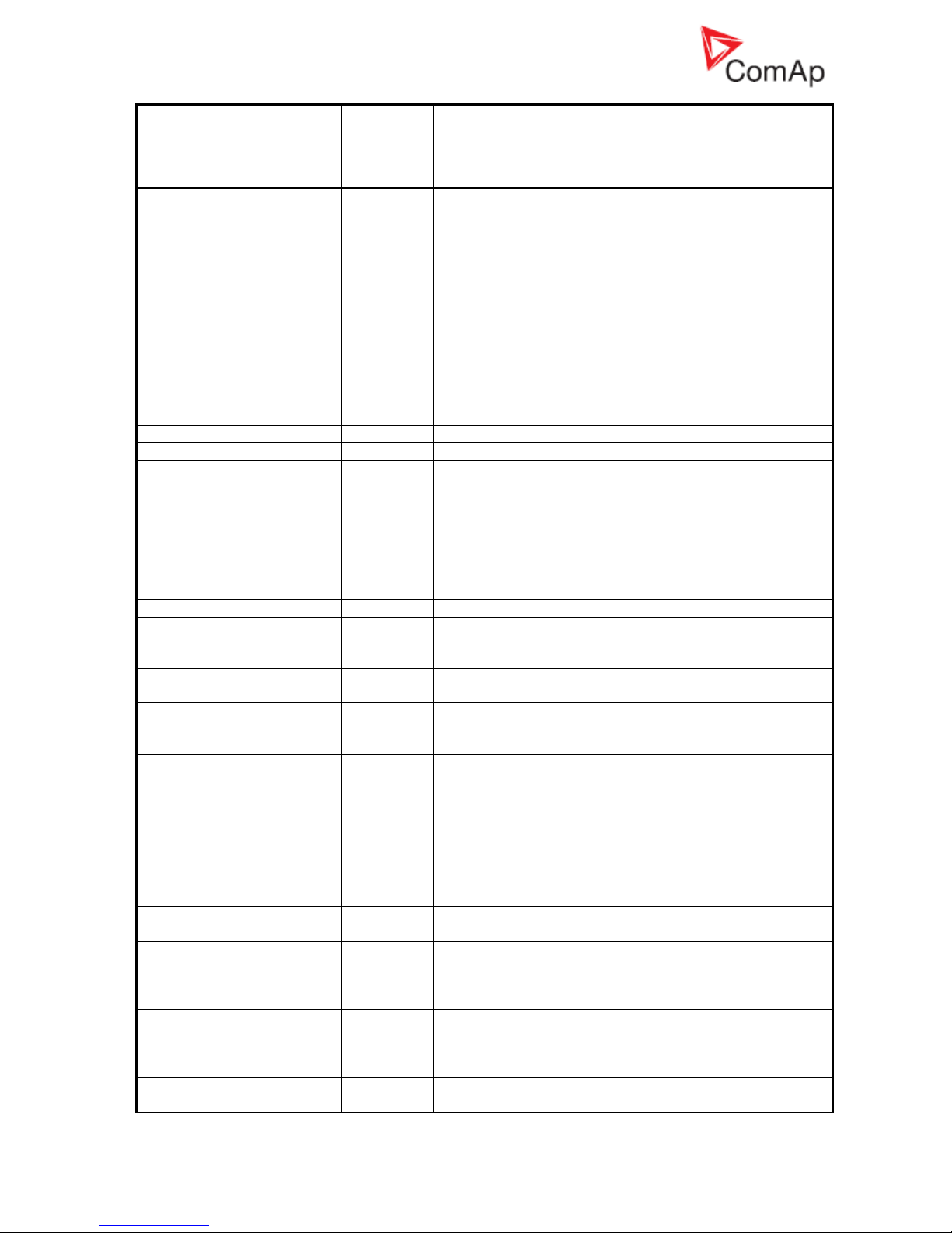
InteliGenNT, InteliSysNT, InteliMainsNT – Troubleshooting Guide,
SW version IGS-NT-3.1.0, IM-NT-3.1.0, ©ComAp – August 2018 41
IGS-NT Troubleshooting Guide.pdf
IGS-NT Alarm/History
record
Alarm/
History
Appeara
nce
Description
ENABLED/DISABLED from the password management
window in InteliMonitor (initial status is DISABLED).
Warning “PassInsertBlck” appears in alarm list when
controller is blocked.It is not allowed to insert the password
in case that controller is blocked. There is information that
controller is blocked for next password attempt and time
remaining till the end of blocation instead of password
input window at the terminal screen. The controller is
locked for 5 minutes when the password is 6 times wrong
entered (in case of next 6 wrong attempts (correct
password was not inserted at all) for 30, 60, 120, 240
minutes). Incorrect password message appears in the
history of the controller when the invalid password is used
(“System Log | Incorrect password)
Incorrect password
H
Read information about alarm PassInsertBlck.
AccessCodeSet
H
Controller access code was set
AccessCodeChng
H
Controller access code was changed
Admin action
H
This history record means that user administration
changes were done11. Only User 0 (Administrator) is
allowed to do such changes. These events can be
recorded as Admin action record:
Password reset
Access rights changed
Alias changed
Terminal
H
External terminal was either connected or disconnected
BinaryUnstable
H
Unstable binary input, this problem is usually caused by
floating binary input ground. Check controller grounding to
fix the problem.
ForceValue
H
Indication of any configured ForceValue state. Force value
ON and OFF records are done.
TimeModeChange
H
Indication of TimeModeChange (summer/winter). Setpoint
Date/Time: #SummerTimeMod is used to do time mode
changes.
GroupsLinked
H
This history record means that two groups of gensets were
connected together, binary input function GroupLink is
used for the state indication. Setpoints Pwr management:
GroupLinkLeft and GroupLinkRight gives you information
which groups of gensets are in parallel if binary input
function GroupLink is active.
GroupsUnlinked
H
Binary input function GroupLink was deactivated. It means
that two groups of gensets, which were working in parallel,
were disconnected from each other.
Time stamp
H
Regular Time stamp record. See setpoints
Date/Time:Time stamp act and Time stamp per.
Gen Peak start
H
Indication of genset start by automatic Peak start/stop
function. See setpoints ProcessControl: PeakLevelStart,
PeakLevelStop and PeakAutS/S del for information about
this function.
Gen Peak stop
H
Indication of genset stop by automatic Peak start/stop
function. See setpoints ProcessControl: PeakLevelStart,
PeakLevelStop and PeakAutS/S del for information about
this function.
Gen PMS start
H
Genset was started by Power Management
Gen PMS stop
H
Genset was stopped by Power Management
Page 42

InteliGenNT, InteliSysNT, InteliMainsNT – Troubleshooting Guide,
SW version IGS-NT-3.1.0, IM-NT-3.1.0, ©ComAp – August 2018 42
IGS-NT Troubleshooting Guide.pdf
IGS-NT Alarm/History
record
Alarm/
History
Appeara
nce
Description
Overload
H
Genset overload protection was activated. See setpoints
Gener protect: OverldStrtEval and 2POverldStEvDel.
Be aware that this protection is based on Basic settings:
Nominal power setpoint setting.
Gen start
H
Indication of genset start using the Start button
Gen stop
H
Indication of genset stop using the Stop button
Gen MF start
H
Indication of genset start by the AMF function
Gen MF stop
H
Indication of genset stop by the AMF function
Gen Rem start
H
Indication of genset start using the Rem start/stop binary
input
Gen Rem stop
H
Indication of Gen-set stop using the Rem start/stop binary
input
Load Shed
H
Load Shedding function was activated and corresponding
LdShed stage x output was closed. See description of
setpoints in the Load shedding group of setpoints.
Load Reconnect
H
Load Shedding function was deactivated and
corresponding LdShed stage x output was opened. See
description of setpoints in the Load shedding group of
setpoints.
VectorShift
H
Indication of VectorShift protection activation.
See setpoints Mains protect:VectorS prot and VectorS
limit.
Other CB trip
H
Other CB on bus was tripped. This information is available
for breakers which are controlled by a ComAp controller
(IG/IS-NT or IM-NT).
GCB opened
H
GCB was opened
GCB closed
H
GCB was closed
MCB opened
H
MCB was opened
MCB opened ext
H
MCB was opened externally
MCB closed
H
MCB was closed
MGCB opened
H
MGCB was opened
MGCB closed
H
MGCB was closed
BTB opened
H
BTB was opened
BTB opened ext
H
BTB was opened externally
BTB closed
H
BTB was closed
SyncStarted
H
Forward synchronization was started
RevSyncStarted
H
Reverse synchronization was started
Ready
H
Genset is ready to be started
Idle run
H
Engine was started (“engine started” conditions were
fulfilled) and engine speed and generator voltage goes up
to nominal values during the Idle run state.
Running
H
Genset is running and GCB can be closed or
synchronisation started.
Warming
H
Indication of Warming function activation. In case of
operation in parallel with mains is genset load reduced to
Warming load level. For more information about this
function see setpoints Engine params: Warming
load, Warming temp, Max warm time.
Soft load
H
Genset load is increased according to Sync/Load ctrl:
Load ramp, Load gain, Load int, RampStartLevel setpoints
setting.
Loaded
H
Genset is loaded
Soft unload
H
Genset load is decreased according to Sync/Load ctrl:
Load ramp, Load gain and Load int setpoints setting.
Page 43

InteliGenNT, InteliSysNT, InteliMainsNT – Troubleshooting Guide,
SW version IGS-NT-3.1.0, IM-NT-3.1.0, ©ComAp – August 2018 43
IGS-NT Troubleshooting Guide.pdf
IGS-NT Alarm/History
record
Alarm/
History
Appeara
nce
Description
Setpoints Sync/Load ctrl: GCB open level and GCB open
del are related to genset unloading too.
Cooling
H
Engine is cooling down
Emerg man
H
Emerg. manual binary input function is active
Not ready
H
Genset is not ready to start. Controller is either in OFF
mode or any 2nd level alarm is in controller alarm list.
ExcitationON/ ExcitationOFF
H
It indicates activation/deactivation of excitation in case of
configuration the SUS sequence function.
Wrn SUSminPwr
A+H
It indicates that require power from the gen-sets with
activated LBO:ReadyToExcite was not achieved (require
power is set by setpoint #SUS min power).
SUS seq blck
A
Alarm indicates that SUS sequence is required, but
setpoint Gear teeth is equal 0. (SUS sequence require
pick-up sensor for correct function).
SUSseq break-1
H
MCB is closed (in SPTM application).
SUSseq break-2
H
MCB is open (MCB feedback is not active) OR Mains
voltage is higher than 1/3 of setpoint Basic
settings:MainsNomV
(in SPI application).
SUSseq break-3
H
Bus voltage is higher than 1/3 of setpoint Basic
settings:BusNomV (in MINT application).
SUSseq break-4
H
GCB was not closed during the Prestart Time count down.
SUSseq break-5
H
Setpoint SUS control:ExcitationCtrl=EXTERNAL. The LBI:
SUSexcitBlck was not activated before engine start OR it
was deactivated before the LBO: ReadyToExcite activation
1
This alarm may be displayed as Wrn or Sd alarm type. Alarm type depends on Protection upon
module failure setting in Modules card in GenConfig. Available settings are: No Protection,
Warning and Shutdown.
2
See setting of Force Protect functions on the PLC card in GenConfig to find out what PLC State x
texts were changed to.
3
Hold Enter and push Esc to enter the Info screen 1. Push the right arrow → to enter Info screen 2
to read IDch and Dngl strings or controller serial number and Password Decode number
(Pwd.Dec.).
4
You can exchange battery by yourself, but ComAp would not be responsible for controller
damage caused by battery exchange then. See our AS08 – Battery exchange process r1
manual for instructions, if you would like to exchange controller battery by yourself.
5
See Al./Hist. msg column on Protections card in GenConfig to see customized alarm messages
which are related to configurable protections.
6
Speed control related regulation loops are part of the Sync/Load ctrl group of setpoints:
Frequency regulation loop: Freq gain, Freq int setpoints
Angle regulation loop: Angle gain setpoint
Load regulation loop: Load ramp, Load gain, Load int setpoints
Load sharing loop: LS gain, LS int setpoints
7
Voltage control related regulation loops are part of the Volt/PF ctrl group of setpoints:
Voltage regulation loop: Voltage gain, Voltage int setpoints
Power Factor regulation loop: PF gain, PF int setpoints
VAr sharing regulation loop: VS gain, VS int setpoints
8
Alarm is related to Generator voltage terminals connection
9
Alarm is related to Mains (Bus) voltage terminals connection
10
In GenConfig go to File - Generate Cfg Image - Generate Cfg Image (Comm.objects) to obtain the
communication objects list
11
In InteliMonitor go to Monitor - Admin Users to do any user administration changes
Page 44

InteliGenNT, InteliSysNT, InteliMainsNT – Troubleshooting Guide,
SW version IGS-NT-3.1.0, IM-NT-3.1.0, ©ComAp – August 2018 44
IGS-NT Troubleshooting Guide.pdf
12
Alarm is related to Mains (Bus-L) voltage terminals connection
13
Alarm is related to Bus (Bus-R) voltage terminals connection
14
Wrong phases sequence means that e.g. generator/Mains voltages rotation is counter clockwise.
Typical reason is that two phases are swapped, e.g. phase L2 is connected to L3 controller
voltage terminal and phase L3 is connected to L2 controller voltage terminal.
15
Adjust setting of incorrectly set setpoints to get rid of the alarm. Use InteliMonitor to do that,
setpoints with out of range/incorrect setting are marked with yellow background
16
Use InteliMonitor to adjust incorrectly set statistics value. Go to Monitor and Set statistics… to do
that.
17
It happens if 12V battery is used as power supply and voltage drops during engine starting (due to
high starter current). Use the I-LBA module to avoid this problem.
18
See the How to check that communication between controllers works chapter for more
information.
19
Check if generator voltage regulation works properly if this alarm is issued. See Volt/PF control
adjustment chapter in IGS-NT-x.y-Reference Guide for information about correct voltage
regulation setting.
20
Check if engine speed regulation works properly if this alarm is issued. See Sync/Load control
adjustment chapter in IGS-NT-x.y-Reference Guide for information about correct engine speed
regulation setting.
21
In GenConfig go to Options/Settings/Display and select Advanced.
22
Check either mains transformer or generator phases connection, one of transformer or generator
phases is connected the other way round (swap transformer or generator coil leads connection).
 Loading...