

Page 1

Reference Guide
InteliMains
NT
®
Bus Tie Breaker Application
IM-NT-BB, IM-NTC-BB, IM-NT
SW version 3.0, May 2013
Copyright ©2013 ComAp a.s.
ComAp a.s.
Kundratka 17, 180 00 Praha 8, Czech Republic
Page 2

2
Table of contents
1 Document information ................................................................................................................... 6
1.1 Clarification of notation ............................................................................................................... 7
1.2 Conformity Declaration ............................................................................................................... 7
2 System overview ............................................................................................................................ 8
2.1 General description .................................................................................................................... 8
2.2 Configurability and monitoring .................................................................................................... 9
2.2.1 GenConfig .......................................................................................................................... 9
2.2.2 InteliMonitor ....................................................................................................................... 9
2.2.3 WinScope ......................................................................................................................... 10
2.2.4 WebSupervisor ................................................................................................................ 10
2.3 Applications overview ............................................................................................................... 10
3 Installation .................................................................................................................................... 11
3.1 IM-NT Installation instructions .................................................................................................. 12
3.1.1 Mounting .......................................................................................................................... 12
3.1.2 Terminal diagram, Dimensions ........................................................................................ 13
3.1.3 Package contents ............................................................................................................ 14
3.1.4 Jumper settings................................................................................................................ 14
3.2 IM-NT-BB and IM-NTC-BB Installation instructions ................................................................. 14
3.2.1 Mounting .......................................................................................................................... 15
3.2.2 Terminal diagram, Dimensions ........................................................................................ 17
3.2.3 Package contents ............................................................................................................ 18
3.2.4 Jumper settings................................................................................................................ 18
3.3 Wiring (general) ........................................................................................................................ 18
3.4 Grounding (general) ................................................................................................................. 19
3.5 Power supply (general)............................................................................................................. 19
3.6 Power supply fusing (general) .................................................................................................. 19
3.7 Voltage and current inputs ....................................................................................................... 20
3.8 Binary Input wiring (general) .................................................................................................... 21
3.9 Binary Output wiring ................................................................................................................. 21
3.9.1 IM-NT ............................................................................................................................... 21
3.9.2 IM-NT-BB and IM-NTC-BB .............................................................................................. 22
3.10 Analog Input and Output wiring ................................................................................................ 23
3.11 CAN and RS485 bus wiring ...................................................................................................... 25
3.11.1 Wiring examples .............................................................................................................. 26
3.12 Extension modules (general) .................................................................................................... 27
4 Putting it into operation ............................................................................................................... 28
4.1 Connection to a controller using PC ......................................................................................... 28
4.1.1 Direct connection ............................................................................................................. 28
4.1.2 Modem connection .......................................................................................................... 29
4.1.3 Internet connection .......................................................................................................... 30
4.1.4 Airgate connection ........................................................................................................... 31
4.1.5 Connection to multiple controllers.................................................................................... 32
4.2 Modification of configuration, setpoints etc. ............................................................................. 33
4.3 Programming of a controller ..................................................................................................... 34
4.3.1 Standard programming .................................................................................................... 34
4.3.2 Programming of non-responsive controller ...................................................................... 34
4.4 Changing the language ............................................................................................................ 37
4.4.1 Selection of the language in InteliMains-NT GC .............................................................. 37
4.4.2 Selection of the language in InteliMains-NT(C)-BaseBox ............................................... 37
4.5 Password management ............................................................................................................ 38
4.5.1 User administration .......................................................................................................... 38
4.5.2 Access group setting in GenConfig ................................................................................. 39
4.5.3 Password break protection .............................................................................................. 39
4.6 Related tools ............................................................................................................................. 41
InteliMainsNT, SW version 3.0
InteliMains-NT-BTB-3.0-Reference Guide.pdf, ©ComAp – June 2013
Page 3

3
5 Operator guide .............................................................................................................................. 42
5.1 IM-NT ........................................................................................................................................ 42
5.2 Systems with InteliVision displays ............................................................................................ 42
6 Firmware and Archives ................................................................................................................ 43
6.1 BaseBox type controllers .......................................................................................................... 43
6.2 Graphical Character type controllers ........................................................................................ 43
7 Function description .................................................................................................................... 44
7.1 Overview ................................................................................................................................... 44
7.2 Modes ....................................................................................................................................... 52
7.2.1 OFF mode ........................................................................................................................ 52
7.2.2 MAN mode ....................................................................................................................... 52
7.2.3 AUT mode ........................................................................................................................ 52
7.3 Process Limitation .................................................................................................................... 53
7.4 Power management ................................................................................................................. 54
7.4.1 Standard Power management ......................................................................................... 54
7.4.2 Load shedding ................................................................................................................. 54
7.5 Remote Alarm Messaging ........................................................................................................ 55
7.5.1 Communication Types for Remote Alarm Messaging ..................................................... 55
7.5.2 Example of setting ........................................................................................................... 56
7.6 Controller Redundancy ............................................................................................................. 57
7.6.1 Redundant systems using binary signals ........................................................................ 57
7.6.2 Redundant systems using CAN bus ................................................................................ 57
7.7 Force value – step by step guide ............................................................................................. 58
7.8 Regulation loops ....................................................................................................................... 59
7.8.1 PI regulation adjustment .................................................................................................. 60
7.9 Values for continuous writing from external sources ................................................................ 61
7.10 General Purpose Timers .......................................................................................................... 61
7.10.1 Timer modes .................................................................................................................... 61
7.11 History Related functions.......................................................................................................... 63
7.11.1 History Records Adjustment ............................................................................................ 63
7.11.2 Time Stamp function ........................................................................................................ 63
7.11.3 Time and Date Intercontroller Sharing ............................................................................. 63
7.11.4 Summer Time Mode ........................................................................................................ 64
7.12 User Buttons ............................................................................................................................. 64
7.13 Remote Control Function.......................................................................................................... 64
7.14 Virtual Peripheral Inputs-Outputs (VPIO) module .................................................................... 65
7.15 Shared Inputs and Outputs ...................................................................................................... 66
7.16 Distributed Binary Inputs and Outputs ...................................................................................... 67
7.17 Modbus Reading and Writing ................................................................................................... 68
7.18 User MODBUS ......................................................................................................................... 68
7.19 Analog Input Sensors and User Sensors ................................................................................. 69
7.20 Languages and Translator tool in GenConfig .......................................................................... 70
7.21 Power Formats ......................................................................................................................... 70
7.22 User Mask function ................................................................................................................... 70
7.23 PLC functions ........................................................................................................................... 71
7.24 Multi language support ............................................................................................................. 71
8 Protections and Alarm management.......................................................................................... 72
8.1.1 Protection groups ............................................................................................................. 72
8.1.2 Protection types ............................................................................................................... 73
8.1.3 Default protections in MCB/MGCB applications .............................................................. 73
8.1.4 Bus left voltage and frequency protections - limits and indications ................................. 74
8.1.5 Bus right voltage and frequency protections - limits and indications ............................... 74
8.1.6 User configurable protections .......................................................................................... 74
8.1.7 Reset Actual Alarms selection ......................................................................................... 77
8.1.8 Bus Measurement Error detection ................................................................................... 77
8.1.9 Peripheral Modules Error detection ................................................................................. 78
9 Circuit breakers operation sequence, MGCB/MCB fail detection .......................................... 79
9.1.1 Related binary inputs: ...................................................................................................... 79
InteliMainsNT, SW version 3.0
InteliMains-NT-BTB-3.0-Reference Guide.pdf, ©ComAp – June 2013
Page 4

4
9.1.2 Related binary outputs: .................................................................................................... 79
9.1.3 Following graphs depict possible CB sequences: ........................................................... 80
9.1.4 Follow function for breaker control in AUT mode ............................................................ 84
10 Controller operation states ................................................................................................... 85
APPENDIX ............................................................................................................................................ 86
11 List of Objects ......................................................................................................................... 87
11.1 Setpoints - List .......................................................................................................................... 87
11.1.1 Setpoints - Process Control ............................................................................................. 87
11.1.2 Setpoints - Basic Settings ................................................................................................ 87
11.1.3 Setpoints - Comms settings ............................................................................................. 87
11.1.4 Setpoints - ComProtSetting ............................................................................................. 88
11.1.5 Setpoints - Analog protect ............................................................................................... 88
11.1.6 Setpoints - BusL protect .................................................................................................. 88
11.1.7 Setpoints - BusR protect .................................................................................................. 89
11.1.8 Setpoints - Pwr management .......................................................................................... 89
11.1.9 Setpoints - Sync ctrl ......................................................................................................... 90
11.1.10 Setpoints - Volt ctrl ........................................................................................................... 90
11.1.11 Setpoints - Force value .................................................................................................... 90
11.1.12 Setpoints - Load shedding ............................................................................................... 91
11.1.13 Setpoints - Timer settings ................................................................................................ 91
11.1.14 Setpoints - Act. calls/SMS ............................................................................................... 91
11.1.15 Setpoints - Date/Time ...................................................................................................... 91
11.2 Values – List ............................................................................................................................. 92
11.2.1 Values group - BusL values ............................................................................................. 92
11.2.2 Values group - BusR values ............................................................................................ 92
11.2.3 Values group - Gen-sets .................................................................................................. 93
11.2.4 Values group - Control loops ........................................................................................... 93
11.2.5 Values group - Pwr management .................................................................................... 93
11.2.6 Values group - Force value .............................................................................................. 93
11.2.7 Values group - Load shedding ......................................................................................... 94
11.2.8 Values group - Analog CU ............................................................................................... 94
11.2.9 Values group - Bin inputs CU .......................................................................................... 94
11.2.10 Values group - Bin outputs CU ........................................................................................ 94
11.2.11 Values group - Log Bout .................................................................................................. 94
11.2.12 Values group - Info .......................................................................................................... 94
11.2.13 Values group - Statistics .................................................................................................. 95
11.3 Binary Input Functions – List .................................................................................................... 95
11.4 Binary Output Functions – List ................................................................................................. 96
11.4.1 Common functions ........................................................................................................... 96
11.4.2 Breaker control................................................................................................................. 97
11.4.3 Status information ............................................................................................................ 97
11.4.4 Fixed protections output .................................................................................................. 97
11.4.5 Power management ......................................................................................................... 98
11.4.6 Configurable protection outputs ....................................................................................... 98
11.5 Analog Input Functions – List ................................................................................................... 98
12 Setpoints ................................................................................................................................. 99
12.1 Password Protection ................................................................................................................. 99
12.2 Table of Setpoints ..................................................................................................................... 99
12.2.1 Group: ProcessControl .................................................................................................... 99
12.2.2 Group: Basic settings ..................................................................................................... 109
12.2.3 Group: Comms settings ................................................................................................. 122
12.2.4 Group: ComProtSetting ................................................................................................. 137
12.2.5 Group: Analog protect .................................................................................................... 139
12.2.6 Group: BusL protect ....................................................................................................... 140
12.2.7 Group: BusR protect ...................................................................................................... 148
12.2.8 Group: Pwr management ............................................................................................... 152
12.2.9 Group: Sync ctrl ............................................................................................................. 170
12.2.10 Group: Volt ctrl ............................................................................................................... 175
InteliMainsNT, SW version 3.0
InteliMains-NT-BTB-3.0-Reference Guide.pdf, ©ComAp – June 2013
Page 5

5
12.2.11 Group: Force value ........................................................................................................ 176
12.2.12 Group: Load shedding ................................................................................................... 189
12.2.13 Group: Timer settings .................................................................................................... 191
12.2.14 Group: Act. calls/SMS .................................................................................................... 196
12.2.15 Group: Date/Time .......................................................................................................... 202
13 Values .................................................................................................................................... 205
13.1 Table of Values ....................................................................................................................... 205
13.1.1 Group: BusL values ....................................................................................................... 205
13.1.2 Group: BusR values ....................................................................................................... 214
13.1.3 Group: Gen-sets values ................................................................................................. 217
13.1.4 Group: Control loops ...................................................................................................... 226
13.1.5 Group: Power management ........................................................................................... 226
13.1.6 Group: Force value ........................................................................................................ 229
13.1.7 Group: Load shedding ................................................................................................... 231
13.1.8 Group: Analog CU ......................................................................................................... 231
13.1.9 Group: Bin inputs CU ..................................................................................................... 233
13.1.10 Group: Bin outputs CU ................................................................................................... 233
13.1.11 Group: Log Bout ............................................................................................................ 234
13.1.12 Group: Info ..................................................................................................................... 237
13.1.13 Group: Statistics............................................................................................................. 245
14 Binary input functions ......................................................................................................... 249
14.1 Virtual and physical modules .................................................................................................. 249
14.2 Table of Binary Input functions ............................................................................................... 250
15 Binary output functions ....................................................................................................... 289
15.1 Virtual and physical modules .................................................................................................. 289
15.2 Table of Binary Output functions ............................................................................................ 290
16 Analog Input functions ........................................................................................................ 322
16.1 Virtual and physical modules .................................................................................................. 322
16.2 Table of Analog Input functions .............................................................................................. 323
17 User Notes ............................................................................................................................. 326
InteliMainsNT, SW version 3.0
InteliMains-NT-BTB-3.0-Reference Guide.pdf, ©ComAp – June 2013
Page 6

6
1 Document information
REVISION NUMBER
RELATED SW. VERSION
DATE
1
3.0
1.3.2012
Pressing F1 in the GenConfig and InteliMonitor setpoint, values or configuration window
will open the help with the context of currently selected setpoint, value and binary input
or output function.
InteliMains-NT® – BTB Reference guide
Written by: Tomáš Vydra
©2013 ComAp a.s.
Kundratka 17, Praha 8, Czech Republic
Phone: +420 246 012 111, Fax: +420 266 316 647
Web: HTTP://WWW.COMAP.CZ, e-mail: info@comap.cz
DOCUMENT HISTORY
InteliMainsNT, SW version 3.0
InteliMains-NT-BTB-3.0-Reference Guide.pdf, ©ComAp – June 2013
Page 7
7
1.1 Clarification of notation
TYPE
TEXT NOTATION
Setpoints in the text
SetpointGroup:SetpointName
Values in the text
ValueGroup:ValueName
Logical Binary/Analog Input/Output functions in the text
LOGICALFUNCTION
Setpoint setting option
OPTION
The following described machine complies with the appropriate basic safety and
health requirement of the EC Low Voltage Directive No: 73/23 / EEC and EC
Electromagnetic Compatibility Directive 89/336 / EEC based on its design and type, as
brought into circulation by us.
HINT
This type of paragraph points out details to help user installation/configuration.
NOTE:
This type of paragraph calls readers’ attention to a notice or related theme.
CAUTION!
This type of paragraph highlights a procedure, adjustment, etc. which may cause damage or improper
functioning of the equipment if not carried out correctly and may not be clear at first sight.
WARNING!
This type of paragraph indicates things, procedures, adjustments, etc. which demand a high level of
attention, otherwise personal injury or death may occur.
EXAMPLE:
This type of paragraph indicates examples of usage for illustrational purposes.
1.2 Conformity Declaration
InteliMainsNT, SW version 3.0
InteliMains-NT-BTB-3.0-Reference Guide.pdf, ©ComAp – June 2013
Page 8

8
2 System overview
2.1 General description
InteliMains-NT controller is comprehensive mains supervision controller for multiple generating sets
operating in parallel to the Mains. A modular construction allow upgrades to different levels of
complexity in order to provide the best solution for various customer applications.
NT Family controllers are equipped with a powerful graphic display showing icons, symbols and bargraphs for intuitive operation, which sets, together with high functionality, new standards in Gen-set
controls.
BaseBox versions of InteliMains controllers is now available. This version features controller without
built-in monochromatic display and can be combined with new and powerful display units InteliVision-8
and InteliVision-5. For more information on these products, please go to comap.cz web pages.
The controller automatically connects and synchronizes two parts of bus bar and controls the bus tie
circuit breaker (BTB).
The key feature of the controller is its easy-to-use operation and installation. Predefined configurations
for typical applications are available as well as user-defined configurations for special applications.
The key features are:
BTB controlled by InteliMains-NT
Highly customizable behavior of breaker control (dead bus, blockation of closing etc.)
Synchronization (voltage and phase matching) of two control groups separated by InteliMains-
BTB with various settings (which group synchronizes to which etc.)
Load shedding control (based on power transferred via BTB)
Full PLC logic included (useful in complex systems – BTB can for example serve as auxiliary
PLC for other controllers)
Support of redundancy controller
Full set of protections for BusL and additional protections for BusR
Group Link function
Active calls and SMS
InteliMainsNT, SW version 3.0
InteliMains-NT-BTB-3.0-Reference Guide.pdf, ©ComAp – June 2013
Page 9
9
2.2 Configurability and monitoring
One of the key features of the controller is the system’s high level of adaptability to the needs of each
individual application and wide possibilities for monitoring. This can be achieved by configuring and
using the powerful ComAp PC/mobile tools.
Supported configuration and monitoring tools:
GenConfig – complete configuration and firmware upgrade
InteliMonitor – multiple site monitoring and setpoint setting
WinScope – special graphical monitoring software
WebSupervisor – web-based system for monitoring and controlling
o WebSupervisor mobile – supporting application for smartphones
NOTE:
Use the GenConfig PC software to read, view and modify configuration from the controller or disk and
write the new configuration to the controller or disk.
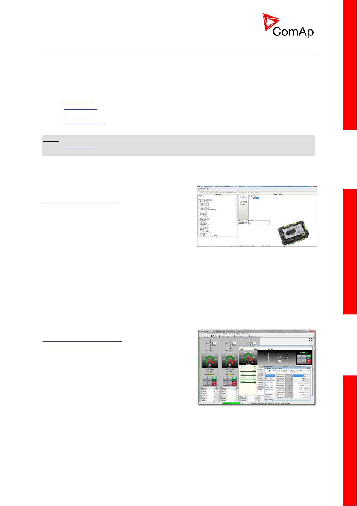
2.2.1 GenConfig
Configuration and monitoring tool for InteliMainsNT,
InteliGenNT and other controllers. See more in
GenConfig Reference Guide.
This tool provides the following functions:
Direct, modem or internet communication with
the controller
Offline or online controller configuration
Controller firmware upgrade
Reading/writing/adjustment of setpoints
Binary/Analog Inputs and Outputs logical functions adjustments
Exporting data into a XLS file
Controller language translation
Screen Editor for editing InteliVision 5 a 8 screens
PLC Editor for editing built-in PLC functions
Updating and configuration of InteliVision 8 firmware
User Protections, User sensor curves, password protection and history management
2.2.2 InteliMonitor
PC Monitoring tool for Inteli controllers. See more in the
InteliMonitor Reference Guide.
This tool provides the following functions:
Online monitoring of a controller or whole site
Fully customizable SCADA diagram
Reading/writing/adjustment of setpoints
Reading of measured values
Browsing of controller history records
InteliMainsNT, SW version 3.0
InteliMains-NT-BTB-3.0-Reference Guide.pdf, ©ComAp – June 2013
Page 10
10
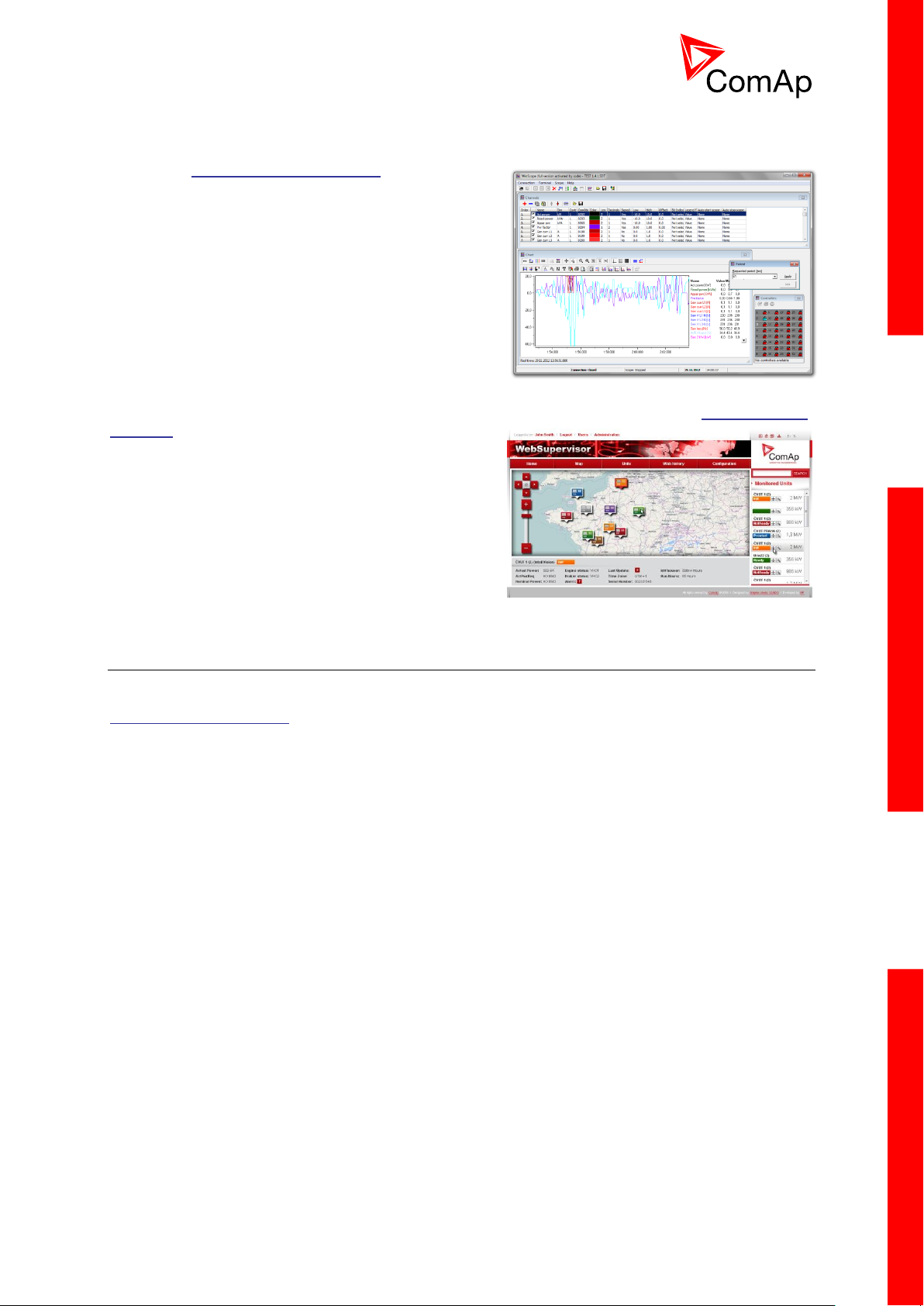
2.2.3 WinScope
Special graphical controller monitoring software. See
more in the WinScope Reference guide.
This tool provides the following functions:
Monitoring and archiving of ComAp controller’s
parameters and values
View of actual/historic trends in controller
On-line change of controllers’ parameters for
easy regulator setup
2.2.4 WebSupervisor
Web-based system for monitoring and controlling ComAp controllers. See more at the WebSupervisor
webpage.
This tool provides the following functions:
Site and fleet monitoring
Reading of measured values
Browsing of controller history records
On-line notification of alarms
E-mail notification
Also available as a smartphone application
2.3 Applications overview
For detailed description of several possible applications using InteliMainsNT please refer to the
IGS-NT-Application Guide.
InteliMainsNT, SW version 3.0
InteliMains-NT-BTB-3.0-Reference Guide.pdf, ©ComAp – June 2013
Page 11
11
3 Installation
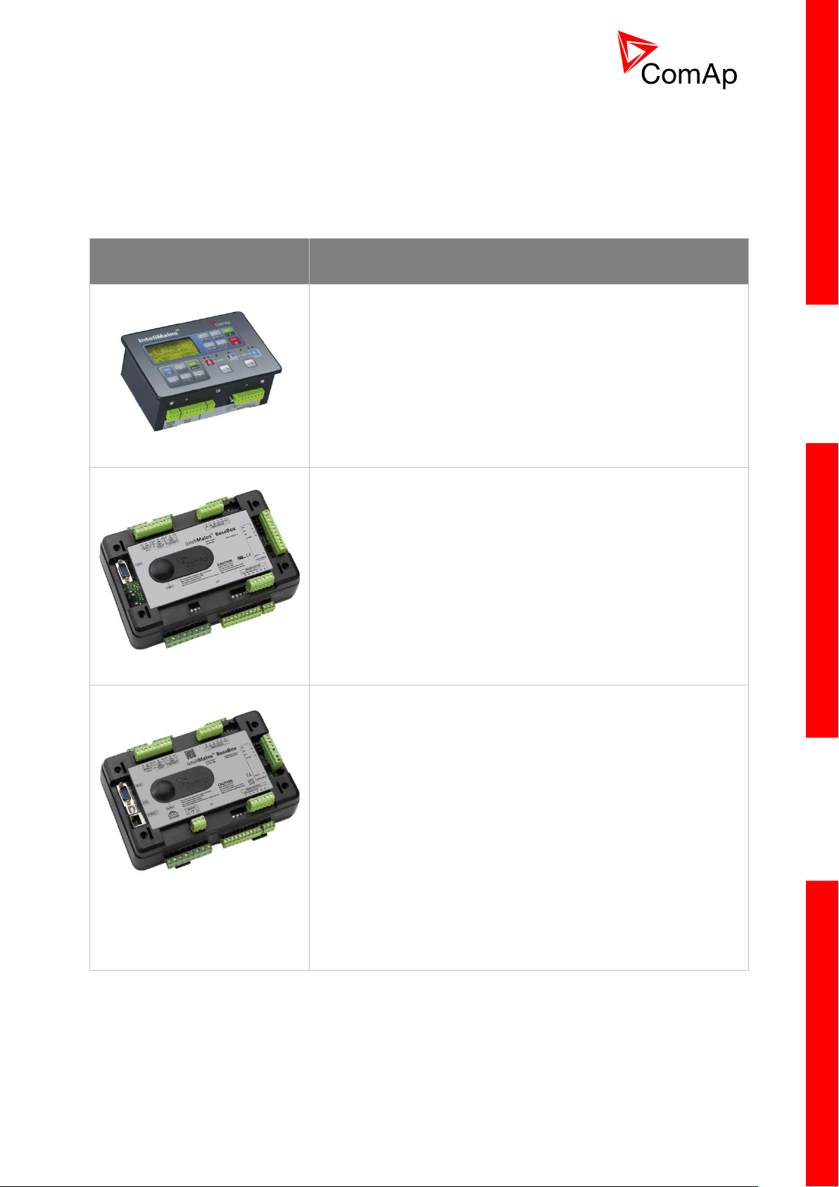
CONTROLLER TYPE
HARDWARE FEATURES
IM-NT
6 Binary Outputs
6 Binary Inputs
Mains and Bus Voltage measurement (3-phase)
Mains Current measurement (3-phase)
Auxiliary Current measurement (1-phase)
RS485 Communication port for universal use
RS232 Communication port
CAN1 Communication port (for extension modules)
CAN2 Communication port (for intercontroller
communication and monitoring)
IM-NT-BB
12 Binary Outputs
12 Binary Inputs
3 Analog Inputs
1 Analog Output
Mains and Bus Voltage measurement (3-phase)
Mains Current measurement (3-phase)
Auxiliary Current measurement (1-phase)
RS485 Communication port dedicated for display
RS232 Communication port
CAN1 Communication port (for extension modules)
CAN2 Communication port (for intercontroller
communication and monitoring)
IM-NTC-BB
12 Binary Outputs
12 Binary Inputs
3 Analog Inputs
1 Analog Output
Mains and Bus Voltage measurement (3-phase)
Mains Current measurement (3-phase)
Auxiliary Current measurement (1-phase)
RS485 Communication port dedicated for display
RS485 Communication port for universal use with galvanic
separation
RS232 Communication port
CAN1 Communication port (for extension modules)
CAN2 Communication port (for intercontroller
communication and monitoring)
USB Communication port
RJ45 (Ethernet) Communication port
There are currently three HW versions of InteliMainsNT controller. Please refer to the corresponding
portion of this chapter for installation instruction for your particular controller type. Chapters relevant
for both HW configurations are marked as “(general)”.
InteliMainsNT, SW version 3.0
InteliMains-NT-BTB-3.0-Reference Guide.pdf, ©ComAp – June 2013
Page 12
12
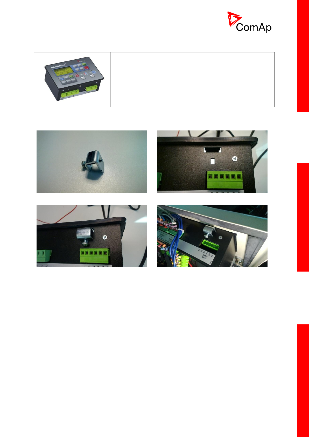
3.1 IM-NT Installation instructions
This portion of Instalation instructions is dedicated to the
InteliMains-NT-GC controller with built-in display. If you have
BaseBox type of the controller (without the built-in display), please
refer to the section 3.2.
Prepare the screw holders
Locate four sockets for screw holders
Insert the unit into cut-out in a switchboard and
insert all four screw holders accordingly to their
positions
Tighten as required to fix the controller in the
position
3.1.1 Mounting
InteliMainsNT, SW version 3.0
InteliMains-NT-BTB-3.0-Reference Guide.pdf, ©ComAp – June 2013
Page 13
13
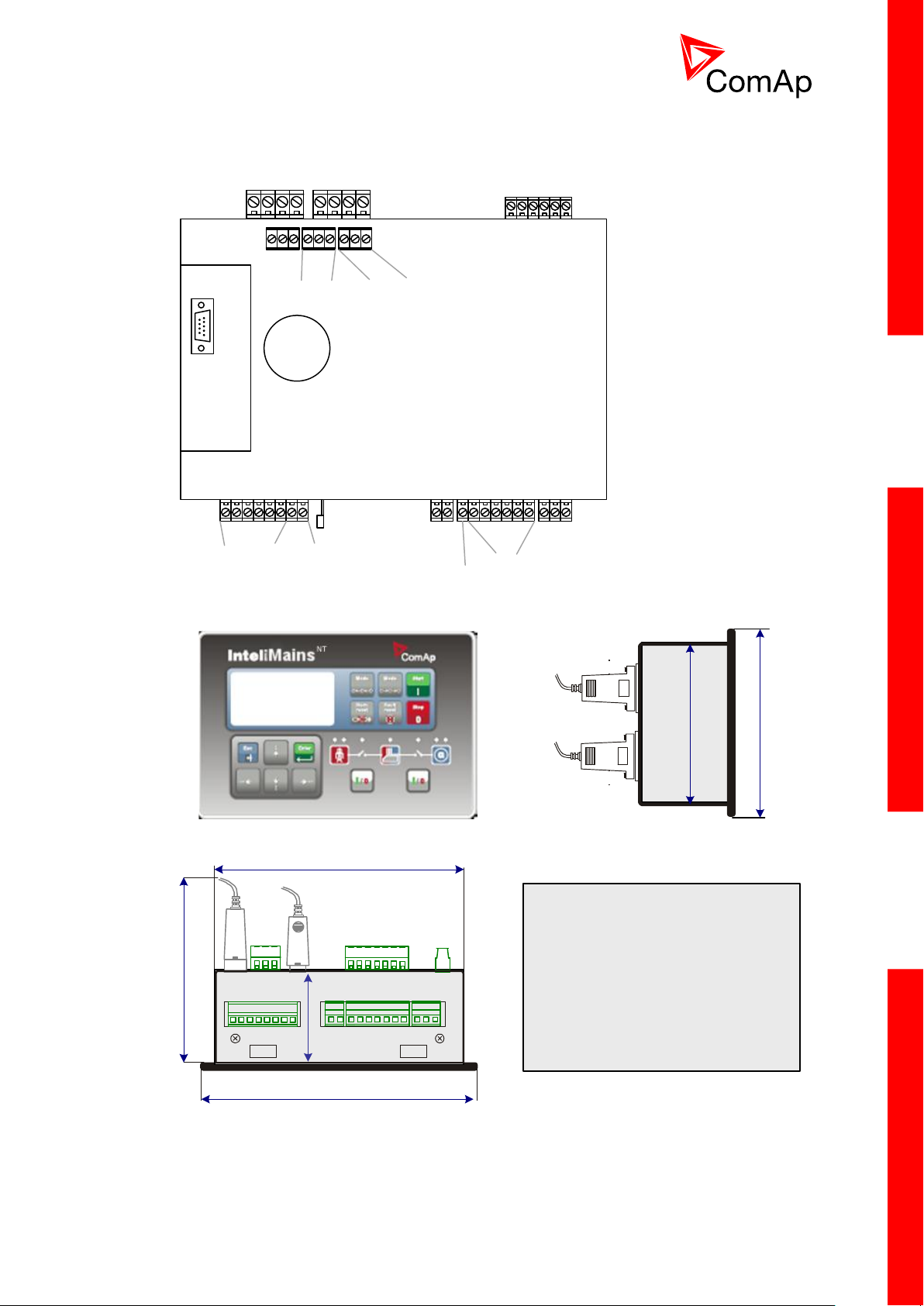
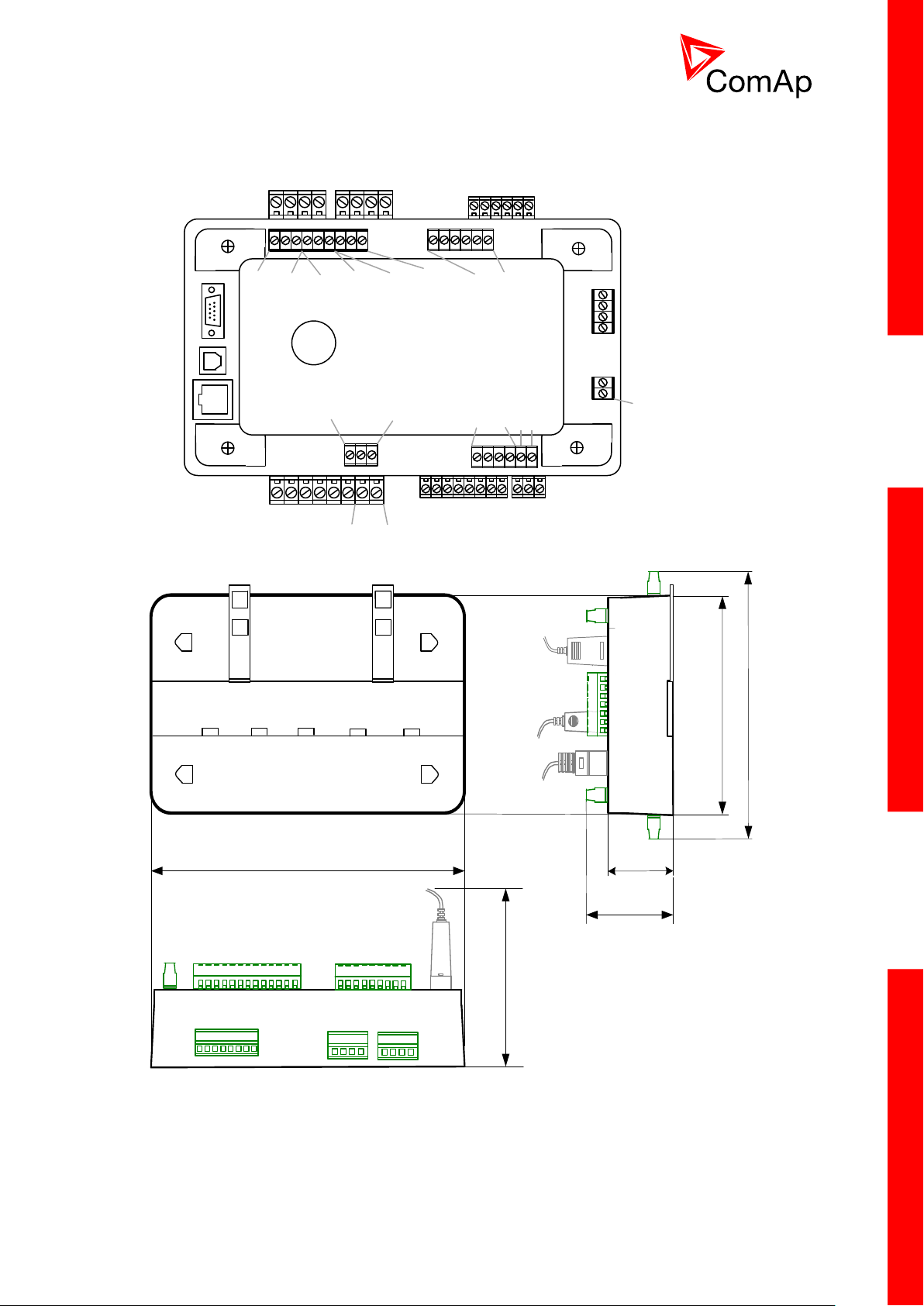
3.1.2 Terminal diagram, Dimensions
Mains Bus
Voltage measurement
Binary inputs
RS232
Current measurement
Mains Aux
Binary outputs
N/A
+PWR BOUT
Grounding
RS485
CAN1
Extension
CAN2
Intercontroller
170 (6,7")
185 (7,3")
123 (4,8“)
RS232
USB
68
2,7“
Cutout for IG-XX/IM-NT
113 x 175 mm
4,4 x 6,9”
123 (4,8“)
110 (4,3“)
InteliMainsNT, SW version 3.0
InteliMains-NT-BTB-3.0-Reference Guide.pdf, ©ComAp – June 2013
Page 14
14
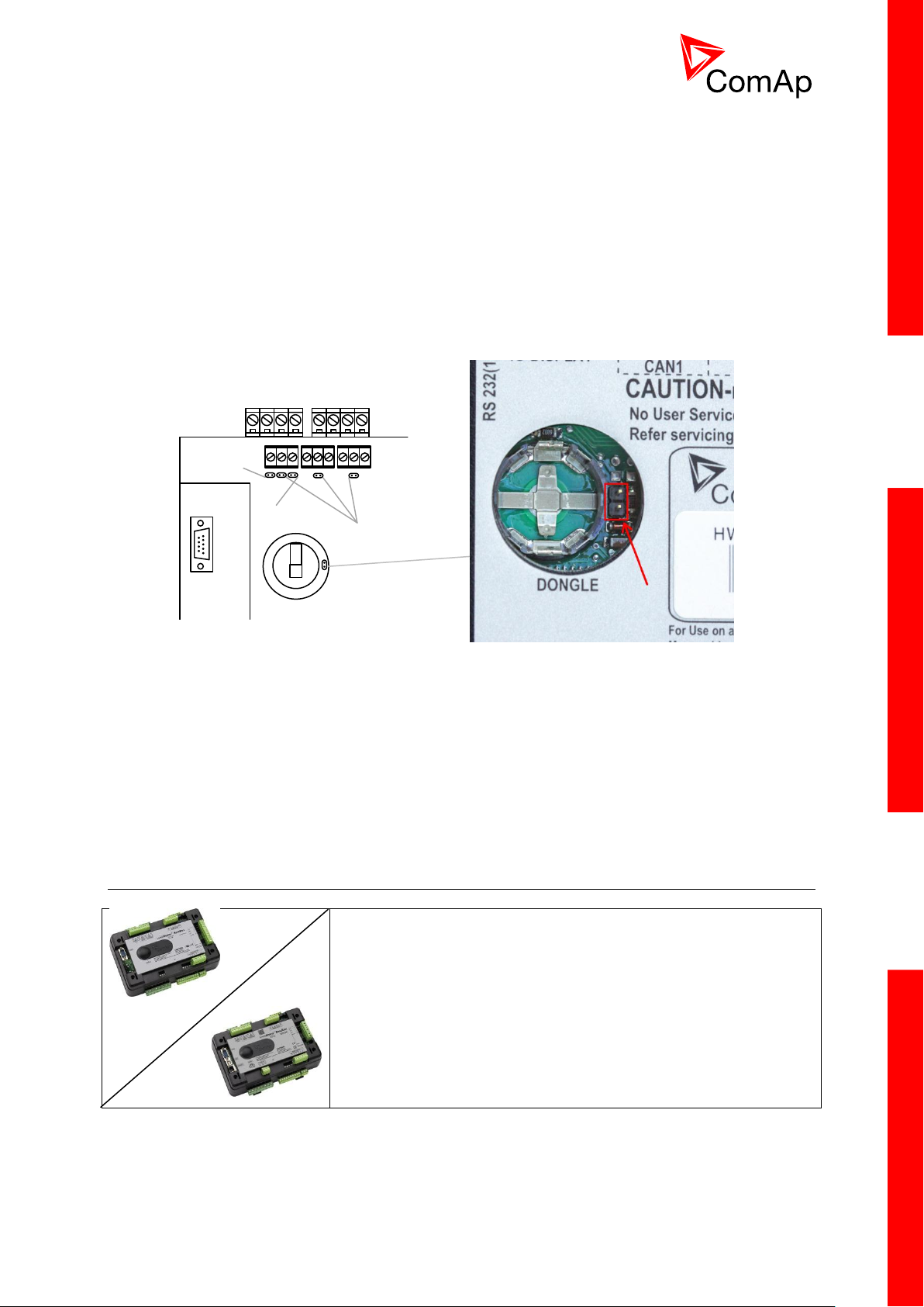
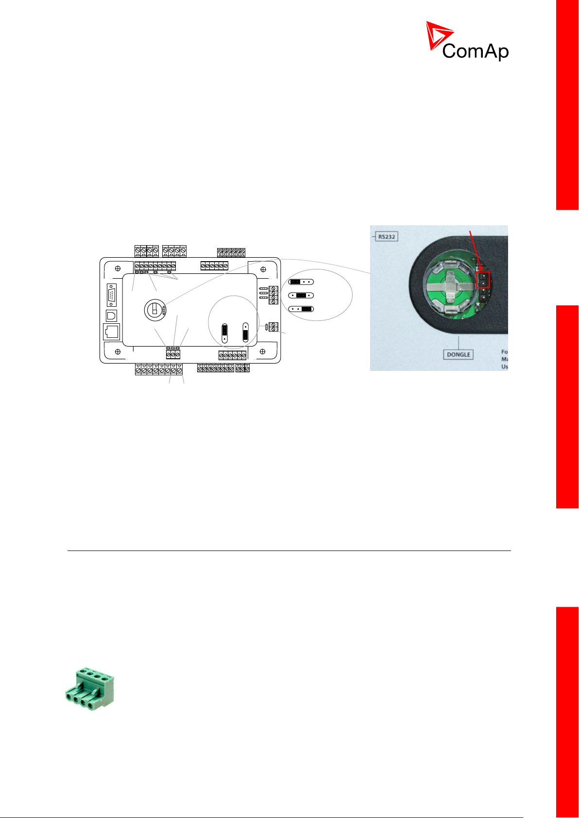
3.1.3 Package contents
Voltage measurement
RS232
120 Ω
terminators
Pull up
Pull down
This portion of Instalation instructions is dedicated to the
InteliMains-NT-BaseBox and InteliMains-NTC-BaseBox
controllers without built-in display. If you have version with built-in
display of the controller, please refer to the section 3.1.
Boot jumper location
The package contains:
Controller
Mounting holders
Terminal blocks
3.1.4 Jumper settings
There are several jumpers available on the unit. Their location and purpose is described below.
Use boot jumper if controller is not responding to communication (e.g. due to faulty programming
sequence). Take off the rubber cover using screwdriver to acces boot jumper next to dongle slot.
Use 120 Ω terminators at the end of CAN1, CAN2 or RS485 buses. Do not use these terminators on
units that are not terminating the bus.
Use pull up and pull down resitors on RS485 to bias the line when no device is active on the bus to
prevent noise from undriven line to be interpreted as data.
3.2 IM-NT-BB and IM-NTC-BB Installation instructions
InteliMainsNT, SW version 3.0
InteliMains-NT-BTB-3.0-Reference Guide.pdf, ©ComAp – June 2013
Page 15
15
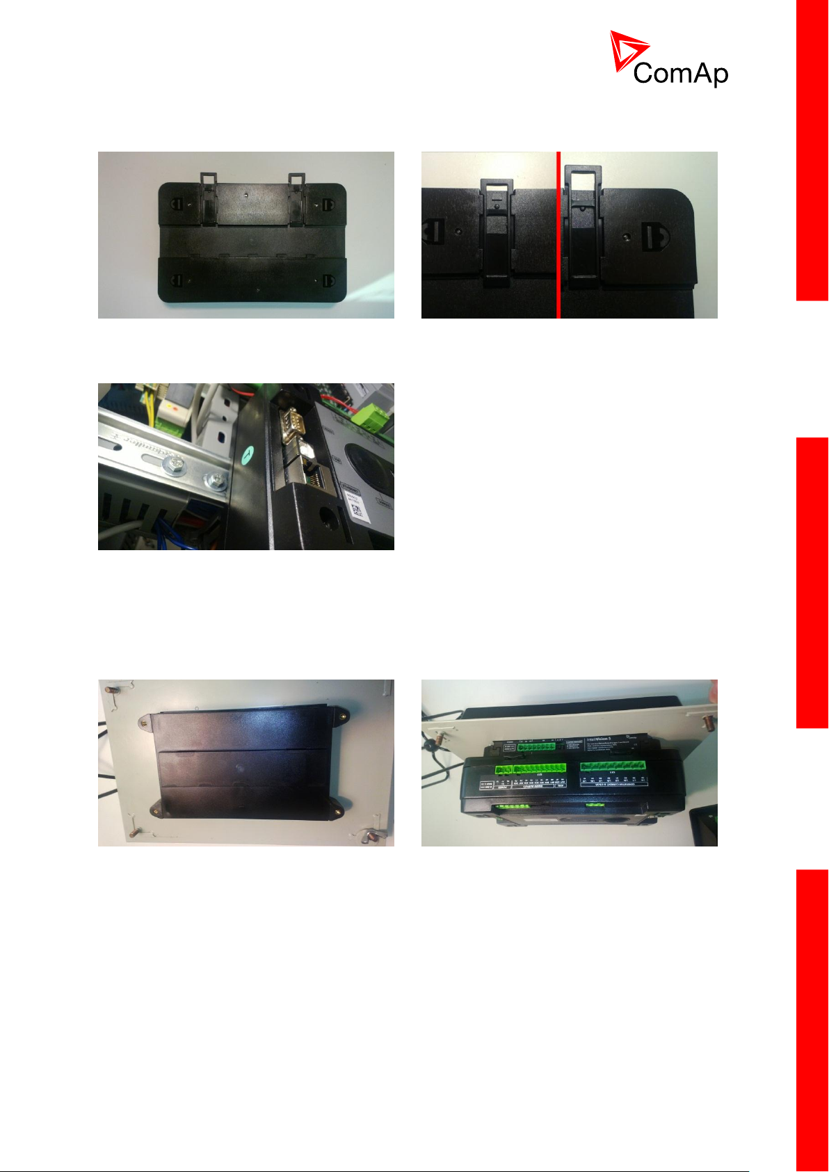
3.2.1 Mounting
Locate two plastic holders on the back side of the
controller
Make sure both holders are in open position (right
image). If not (left image) open them by pulling
them slightly out
Mount the unit on the DIN rail and secure by
pressing two plastic holder until they click and fix
the unit into position
Mount InteliVision 5 into the switchboard cut-out
(for more information on InteliVision 5 mounting
please refer to the InteliVision 5 Reference
Guide)
Use the rail provided on the back side of
InteliVision 5 and mount the controller to it while
following the same steps when mounting on
standard rail (rail openings on InteliVision 5 are
fixed so there is only one possible way how to
mount the controller to it)
BaseBox units are prepared for mounting on DIN rain mount (35mm).
BaseBox units may also be mounted on InteliVision 5 and together with it mounted into cut-out
in a switchboard.
InteliMainsNT, SW version 3.0
InteliMains-NT-BTB-3.0-Reference Guide.pdf, ©ComAp – June 2013
Page 16

16
Locate four screw holes on the front of the
controller
Insert provided screws and use them to secure
the controller mounted to InteliVision 5 (screws fit
into InteliVision 5 holder pieces)
InteliMainsNT, SW version 3.0
InteliMains-NT-BTB-3.0-Reference Guide.pdf, ©ComAp – June 2013
Page 17
17
3.2.2 Terminal diagram, Dimensions
Mains Bus
Voltage measurement
Binary inputs
1-6
7-12
RS485
Display only
CAN1
Extension
modules
CAN2
Intercontroller
and
monitoring
RS232
USB
(NTC only)
Ethernet
(NTC only)
RS485
Universal
use
(NTC only)
Current measurement
Mains Aux
Binary outputs
1-8
9-12 + -
Binary outputs
Binary inputs
Power
Analog inputs
1-3
AI COM
Analog output
AOUT COM
AOUT -
RS232
56.5
223
110
RS 232
USBRJ 45
68.5
142
166
IM-NTC-BB only
IM-NTC-BB only
InteliMainsNT, SW version 3.0
InteliMains-NT-BTB-3.0-Reference Guide.pdf, ©ComAp – June 2013
Page 18
18
3.2.3 Package contents
Mains Bus
Voltage measurement
Binary inputs
1-6
120 Ω
terminators
RS232
USB
(NTC only)
Ethernet
(NTC only)
Current measurement
Mains Aux
Binary outputs
1-8
Power
AI COM
Analog output
AOUT COM
AOUT -
Pull upPull down
Pull up
Pull down
(NTC only)
Voltage
output
0-10V
Current
output
0-20mA
Voltage input
0-5 VDC
Current input
0-25 mA
Resistance input
0-2400 Ω
120 Ω
terminator
Boot jumper location
The package contains:
Controller
Screws for optional screw mounting
Terminal blocks
3.2.4 Jumper settings
There are several jumpers available on the unit. Their location and purpose is described below.
Use boot jumper if controller is not responding to communication (e.g. due to faulty programming
sequence). Take off the rubber cover using screwdriver to acces boot jumper next to dongle slot.
Use 120 Ω terminators at the end of CAN1, CAN2 or RS485 buses. Do not use these terminators on
units that are not terminating the bus.
Use pull up and pull down resitors on RS485 to bias the line when no device is active on the bus to
prevent noise from undriven line to be interpreted as data.
3.3 Wiring (general)
To ensure proper function:
Tightening torque, allowable wire size and type, for the Field-Wiring Terminals:
InteliMainsNT, SW version 3.0
InteliMains-NT-BTB-3.0-Reference Guide.pdf, ©ComAp – June 2013
Use grounding terminals.
Wiring for binary inputs and analog inputs must not be run with power cables.
Analog and binary inputs should use shielded cables, especially when the length is more than
3 m.
For Mains(Bus) Voltage, Generator Voltage a Current terminals
o Specified tightening torque is 0,56Nm (5,0 In-lb)
o Use only diameter 2,0-0,5mm (12-26AWG) conductor, rated for 90°C
minimum.
Page 19
19
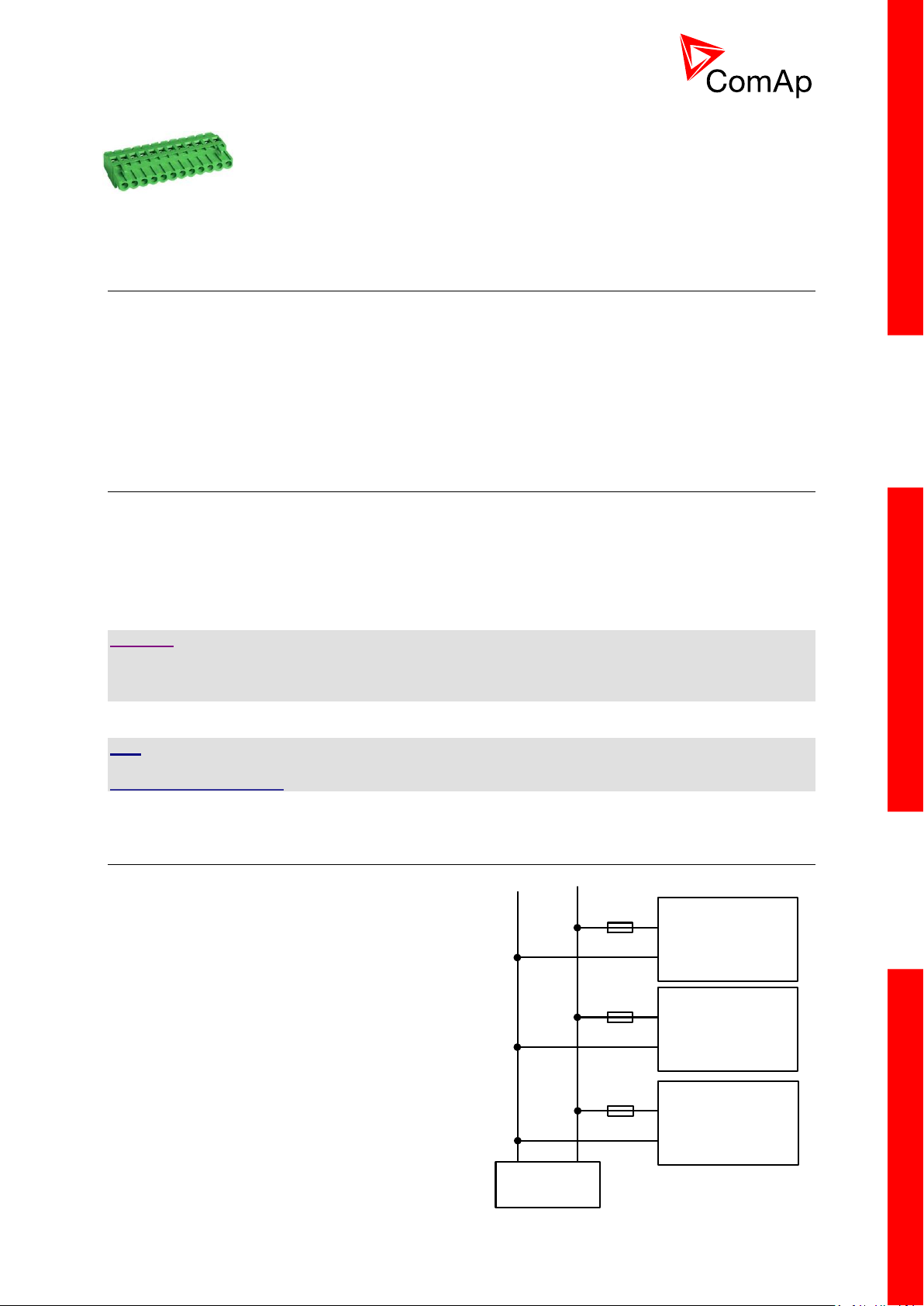
For other controller field wiring terminals
Binary outputs
Battery 24V DC
- +
IM-NT
IM-NT-BB
or
IM-NTC-BB
Extension module
T1A or T2A
T2A
T1A
o Specified tightening torque 0,79Nm (7,0 In-lb)
o Use only diameter 2,0-0,5mm (12-26AWG) conductor, rated for
75°C minimum.
o Use copper conductors only.
3.4 Grounding (general)
The shortest possible piece of wire should be used for controller grounding. Use cable min. 2.5 mm2.
A brass M4x10 screw with star washer securing ring type grounding terminal shall be used.
The negative “-” battery terminal must be properly grounded.
Switchboard and engine must be grounded at a common point. Use as short a cable as
possible to the grounding point.
3.5 Power supply (general)
To ensure proper function:
Use power supply cable min. 2,5mm 2
Use fuse
o 1 amp for IM-NT
o 2 amps for IM-NT-BB or IM-NTC-BB
Maximal continuous DC power supply voltage is 36VDC.
CAUTION!
Switchboard lightning strikes protection according standard regulation is expected!!!
The maximum allowable current through the controller negative terminal is 3 to 8A (depends on the
controller type and binary output load).
HINT
For more information on technical data regarding supply, inputs, outputs etc. please refer to
IGS-NT-Instalation Guide.
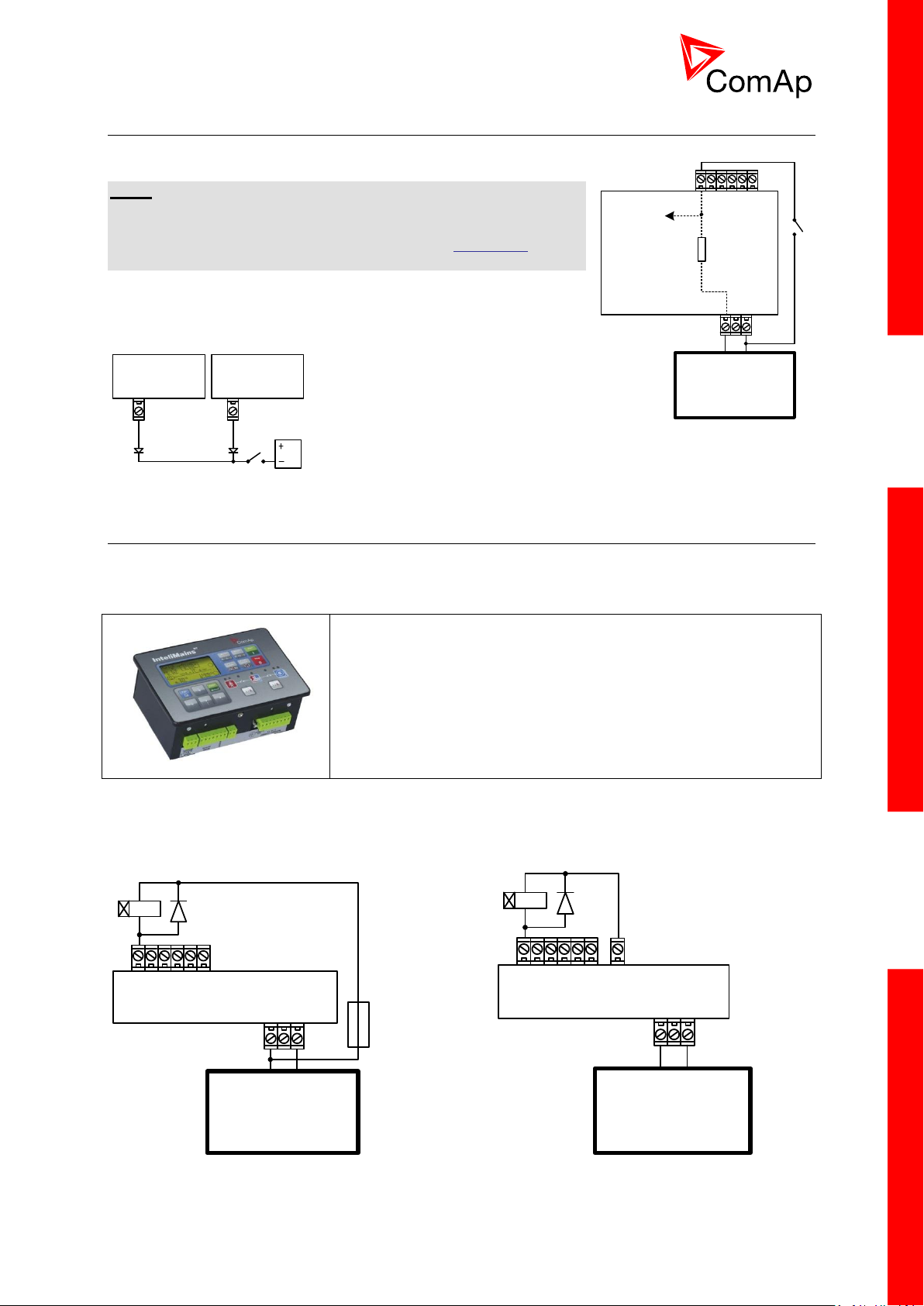
3.6 Power supply fusing (general)
Always use according fuse (1Amp or 2Amps) when
connection controller, extension modules or relays to
a power source.
See the diagram for proper fusing.
InteliMainsNT, SW version 3.0
InteliMains-NT-BTB-3.0-Reference Guide.pdf, ©ComAp – June 2013
Page 20
20
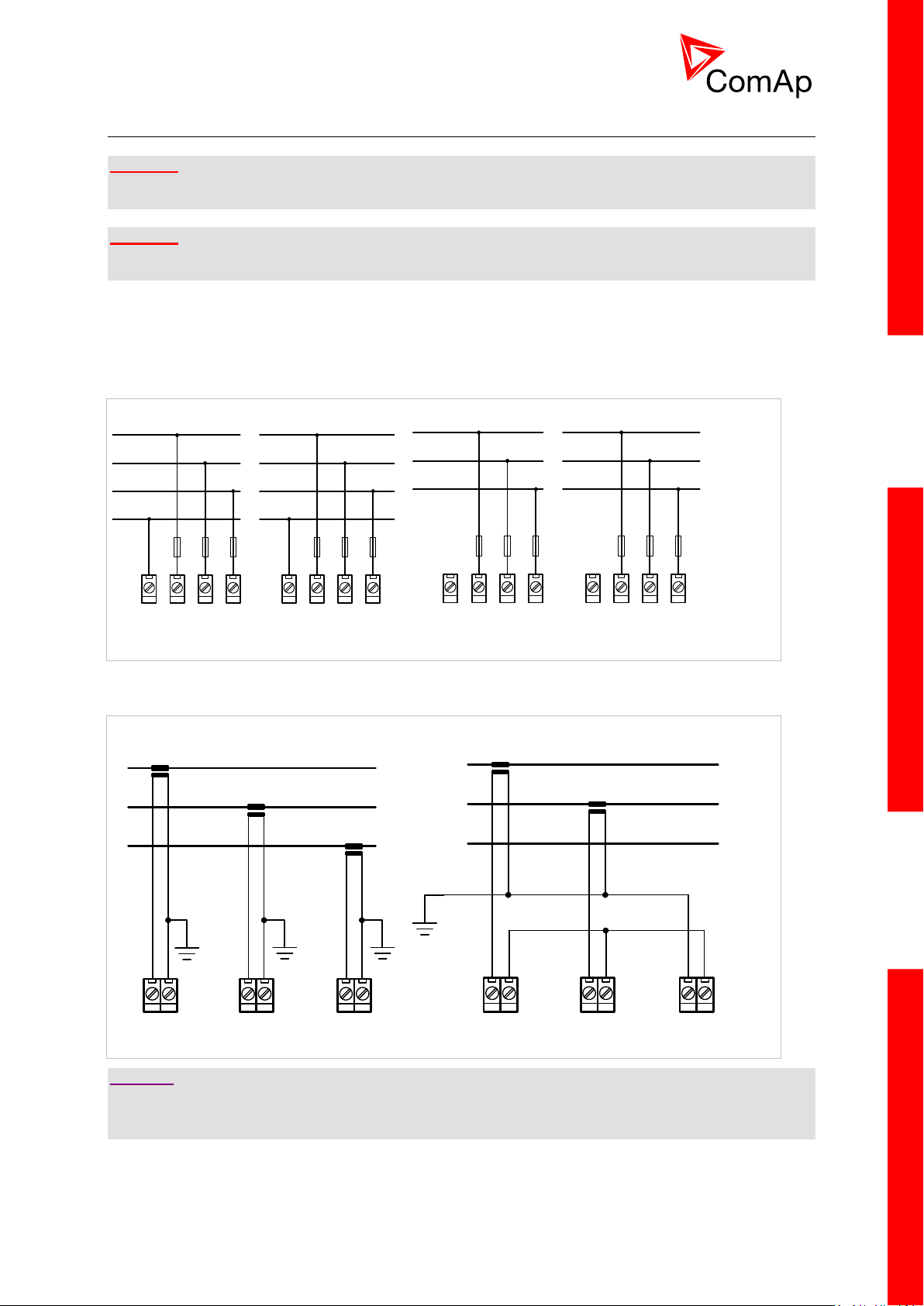
3.7 Voltage and current inputs
A) B)
L1
L2
L3
N
N L3L2L1
MAINS
N L3L2L1
BUS
L1
L2
L3
N L3L2L1
MAINS
N L3L2L1
BUS
A) B)
K
L
k
l
K
L
k
l
K
L
k
l
I1k I1l I2k I2l I3k I3l
K
L
k
l
K
L
k
l
I1k I1l I2k I2l I3k I3l
WARNING!
Risk of personal injury due to electric shock when manipulating voltage terminals under voltage! Be
sure the terminals are not under voltage before touching them.
WARNING!
Do not open the secondary circuit of current transformers when the primary circuit is closed!!! Open
the primary circuit first!
Use 1.5 mm2 cables for voltage connection and 2.5 mm2 for current transformers connection.
Adjust nominal voltage, nominal current, CT ratio and PT ratio by appropriate setpoints in the Basic
Settings group.
VOLTAGE MEASUREMENT WIRING
CURRENT MEASUREMENT WIRING
CAUTION!
Check measurement connections carefully! Failure is possible if phases are connected in wrong order
(WrongPhSequence detected by the controller) but this is not detected if the phases are just rotated
(i.e. instead of phase sequence L1, L2, L3, phase sequence is e.g. L2, L3, L1.
InteliMainsNT, SW version 3.0
InteliMains-NT-BTB-3.0-Reference Guide.pdf, ©ComAp – June 2013
Page 21
21
3.8 Binary Input wiring (general)
IM-NT-BB IM-NT
This portion of Instalation instructions is dedicated to the
InteliMains-NT-GC controller with built-in display. If you have
BaseBox type of the controller (without the built-in display), please
refer to the section 3.8.2.
Controller
Battery 24V
DC
+ -
Controller
Battery 24V
DC
+ -
+PWR BOUT
Battery 24V
DC
+ -
Controller
Internal
4k7
To microprocessor
Use min. 1 mm2 cables for wiring of binary inputs.
NOTE:
The name and function or alarm type for each binary input have to
be assigned during the configuration. Binary inputs may be used in
built-in PLC as well. Please refer to the manual of GenConfig for
more information.
It is recommended to use separation diodes when multiple binary
input terminals are connected together to prevent unwanted
activation of binary input when one of the controllers is switched off.
3.9 Binary Output wiring
3.9.1 IM-NT
Correct wiring for Binary output is shown in the diagram below. On the left +PWR BOUT is not used,
on the right +PWR BOUT is used. If Binary outputs are connected directly to the power source,
additional fuse should be used.
InteliMainsNT, SW version 3.0
InteliMains-NT-BTB-3.0-Reference Guide.pdf, ©ComAp – June 2013
Page 22
22
NOTE:
This portion of Instalation instructions is dedicated to the
InteliMains-NT-BaseBox and InteliMains-NTC-BaseBox
controllers without built-in display. If you have version with built-in
display of the controller, please refer to the section 3.8.1.
Binary outputs
+ -
BO1
Battery 24V
DC
+ -
From
microprocessor
Internal
Binary outputs
+ -
BO1
Battery 24V
DC
+ -
From
microprocessor
Internal
If +PWR BOUT is used, it increases power consumption of the controller.
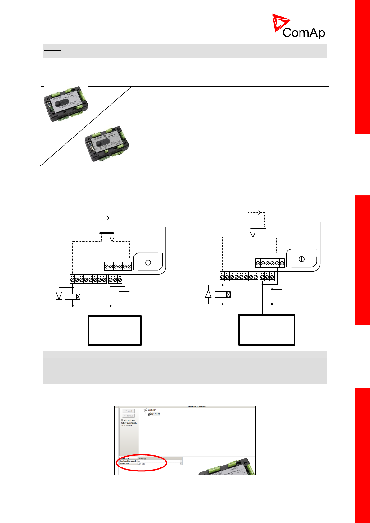
3.9.2 IM-NT-BB and IM-NTC-BB
It is possible to use binary outputs as low side switch or high side switch in BaseBox type of controller.
For correct wiring in both cases please refer to the following diagrams.
Low side switch High side switch
CAUTION!
Both power supply sockets for binary outputs need to be connected to ensure proper function of binary
outputs.
Never use DC relays without protection diods!
Low side or High side function of binary outputs can be chosen in configuration tool GenConfig in
Modules tab. This configuration is used for all binary inputs available on the controller.
InteliMainsNT, SW version 3.0
InteliMains-NT-BTB-3.0-Reference Guide.pdf, ©ComAp – June 2013
Page 23
23
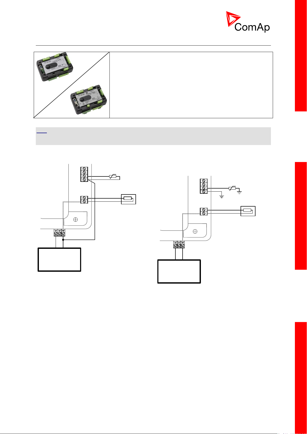
3.10 Analog Input and Output wiring
This portion of Instalation instructions is dedicated to the
InteliMains-NT-BaseBox and InteliMains-NTC-BaseBox
controllers without built-in display. Analog inputs and output are not
available in InteliMains-NT-GC.
Resistive sensor on Analog input 3 and Analog
output wiring
Battery 24V
DC
+ -
AI3
AI COM
Internal
AOUT
COM
AOUT +
Resistive sensor with grounding on Analog input
3 and Analog output wiring. Note, that battery
should be also grounded to common ground
in all cases!
Battery 24V
DC
+ -
AI3
AI COM
Internal
AOUT
COM
AOUT +
HINT
For more information on technical data regarding supply, inputs, outputs etc. please refer to
For jumper setting of Analog inputs please refer to the section 3.2.4 Jumper settings.
InteliMainsNT, SW version 3.0
InteliMains-NT-BTB-3.0-Reference Guide.pdf, ©ComAp – June 2013
Page 24
24
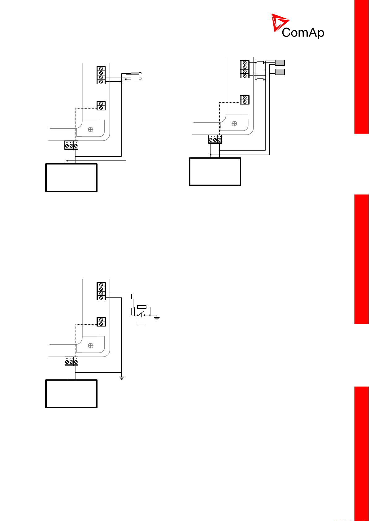
Passive Current sensor on Analog input 3 and
Active Current sensor on ANalog input 2
Battery 24V
DC
+ -
AI3
AI COM
Internal
AOUT
COM
AOUT +
AI2
Voltage sensors on Analog input 1 and 3
Battery 24V
DC
+ -
AI3
AI COM
Internal
AOUT
COM
AOUT +
AI1
10K
10K
Tristate sensor (binary sensor with fail detection)
on Analog input 3
Below 750Ω = Inactive
Between 750Ω and 2400Ω = Active
Below 10 Ω or Over 2400Ω = sensor failure
(wire shorted or interrupted)
Battery 24V
DC
+ -
AI3
AI COM
Internal
AOUT
COM
AOUT +
P
100R
1k5
InteliMainsNT, SW version 3.0
InteliMains-NT-BTB-3.0-Reference Guide.pdf, ©ComAp – June 2013
Page 25
25
3.11 CAN and RS485 bus wiring
Cable type
Shielded twisted pair
Impedance
120 Ω
Propagation velocity
≥ 75% (delay ≤ 4.4 ns/m)
Wire crosscut
≥ 0.25 mm2
Attenuation (@1MHz)
≤ 2dB/100 m
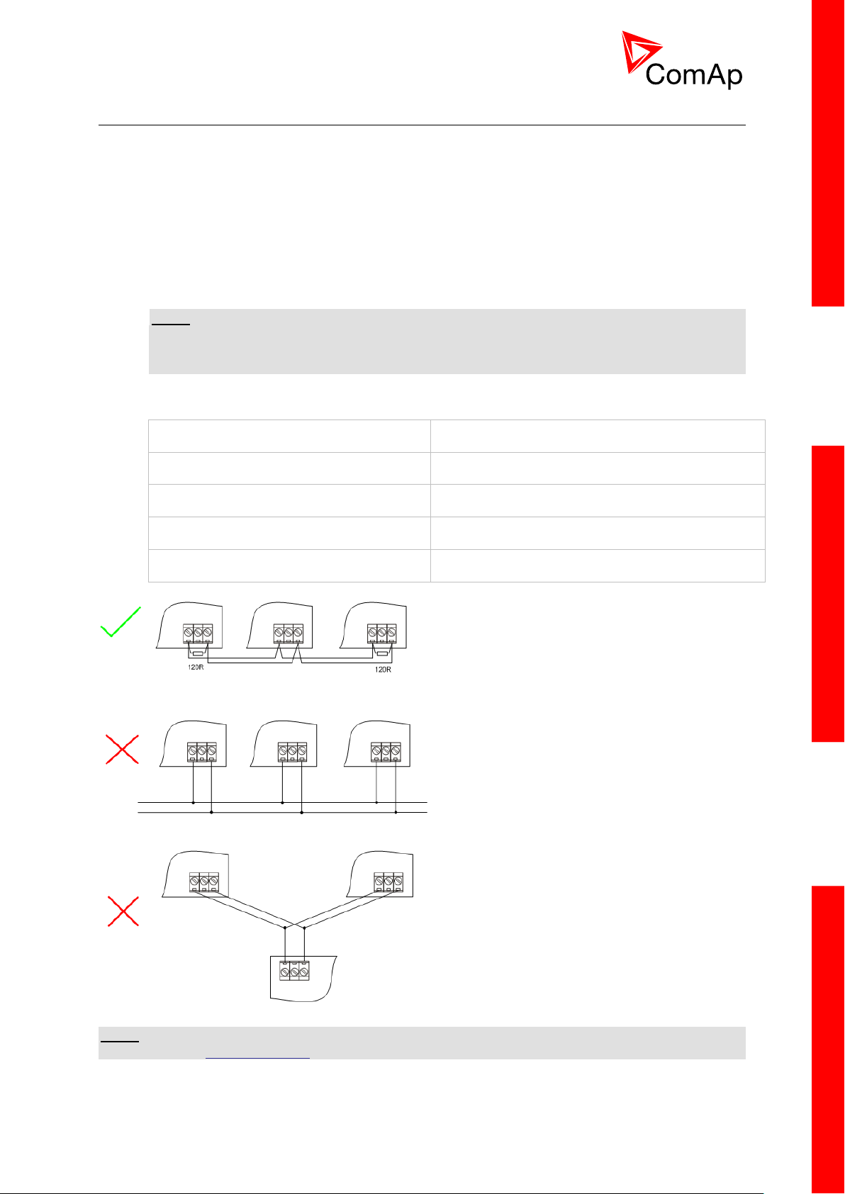
The wiring of the CAN bus communication should be provided in such a way that the following rules
are observed:
The maximum length of the CAN bus depends on the communication speed. For a speed of
250 kbps, which is used on the CAN1 bus (extension modules, ECU) and CAN2 bus if it is
switched to 32C mode, the maximum length is 200 m. If the CAN2 bus is switched to 8C mode
the speed is 50 kbps and the maximum length is 800 m.
The maximum length of the RS485 bus is 1000 m
The bus (CAN and RS485) must be wired in linear form with termination resistors at both
ends. No nodes are allowed except on the controller terminals.
NOTE:
A termination resistors at the CAN and RS485 are already implemented on the PCB. For
connecting, close the jumper near the appropriate CAN or RS485 terminal. For more
information on jumper settings please refer to the section 3.1.4 Jumper setting.
Use a cable with following parameters:
CAN AND RS485 BUS TOPOLOGY
NOTE:
See the website www.can-cia.org for information about the CAN bus, specifications, etc.
InteliMainsNT, SW version 3.0
InteliMains-NT-BTB-3.0-Reference Guide.pdf, ©ComAp – June 2013
Page 26
26
3.11.1 Wiring examples
1. For shorter distances (all network components within one room) – picture 1
interconnect A and B; shielding connect to PE on controller side
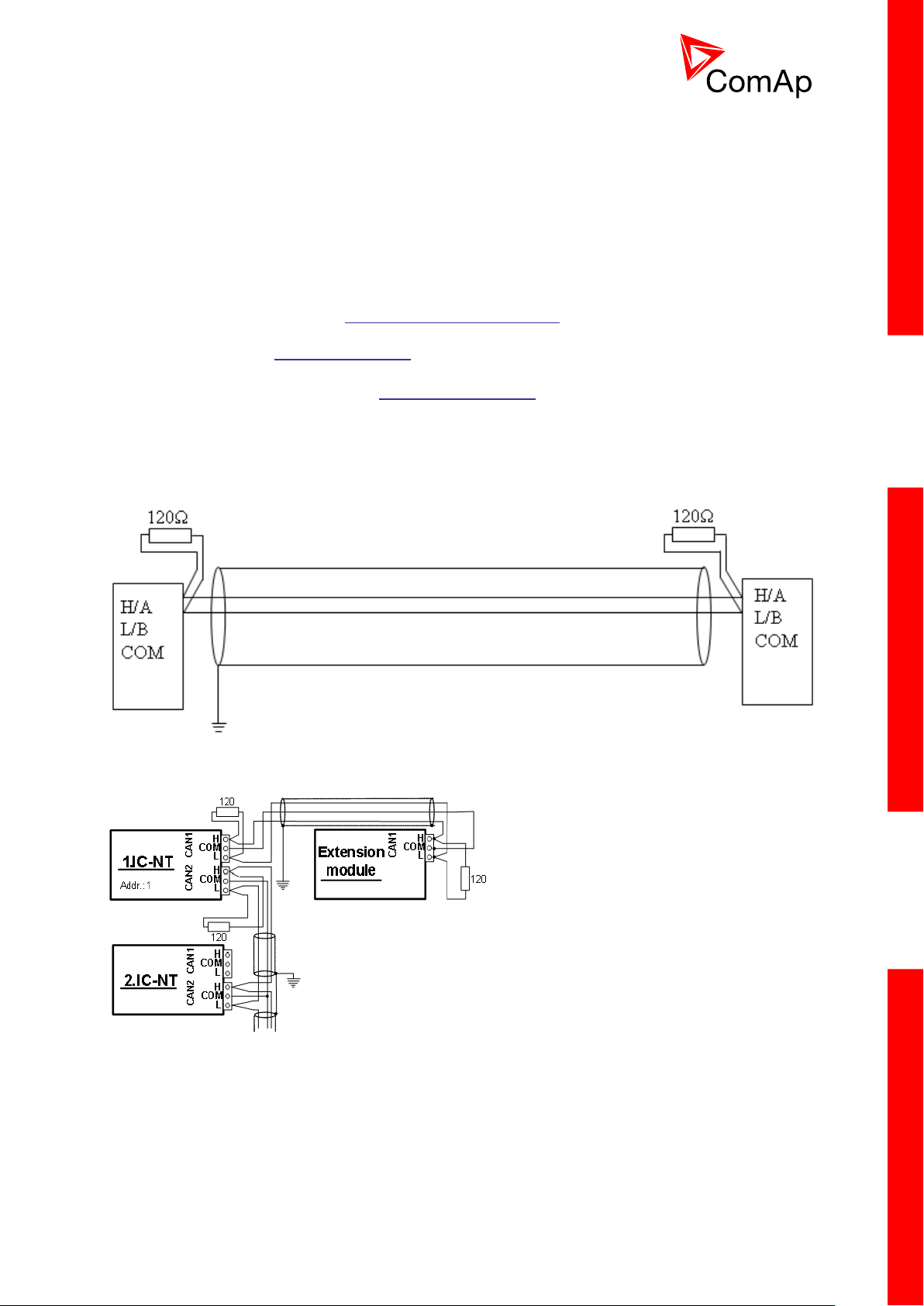
2. For longer distances (connection between rooms within one building) – picture 2
interconnect A, B, COM; shielding connect to PE at one point
3. In case of surge hazard (connection out of building in case of storm etc.) – picture 3
We recommend using the following protections:
Phoenix Contact (http://www.phoenixcontact.com): PT 5-HF-5DC-ST with PT2x2-BE
(base element)(or MT-RS485-TTL)
Saltek (http://www.saltek.cz): DM-006/2 R DJ
Recommended data cables: BELDEN (http://www.belden.com)
1. For shorter distances: 3105A Paired – EIA Industrial RS-485 PLTC/CM (1x2 conductors)
2. For shorter distances: 3105A Paired – EIA Industrial RS-485 PLTC/CM (1x2 conductors)
3. In case of surge hazard: 3106A Paired – EIA Industrial RS-485 PLTC/CM (1x2+1 conductors)
PICTURE 1 – SHORTER DISTANCES (ALL NETWORK COMPONENTS WITHIN ONE ROOM)
PICTURE 2 – LONGER DISTANCES (CONNECTION BETWEEN ROOMS WITHIN ONE BUILDING)
InteliMainsNT, SW version 3.0
InteliMains-NT-BTB-3.0-Reference Guide.pdf, ©ComAp – June 2013
Page 27

27
PICTURE 3 – SURGE HAZARD (CONNECTION OUT OF BUILDING IN CASE OF STORM ETC.)
3.12 Extension modules (general)
For detailed description of several available extension modules for InteliMainsNT please refer to the
IGS-NT-Instalation Guide.
InteliMainsNT, SW version 3.0
InteliMains-NT-BTB-3.0-Reference Guide.pdf, ©ComAp – June 2013
Page 28
28
4 Putting it into operation
GenConfig
InteliMonitor
In this section brief introduction how to
connect to a controller,
modify various settings,
program controller and reprogram non-responsive controller,
manage passwords and password protections and
operate related tools (ScreenEditor, PLC Editor etc.)
is presented.
4.1 Connection to a controller using PC
There are several available ways to connect to controller using PC for monitoring, control or
configuration/programming. For more information on related PC tools please refer to the section
2.2 Configurability and monitoring.
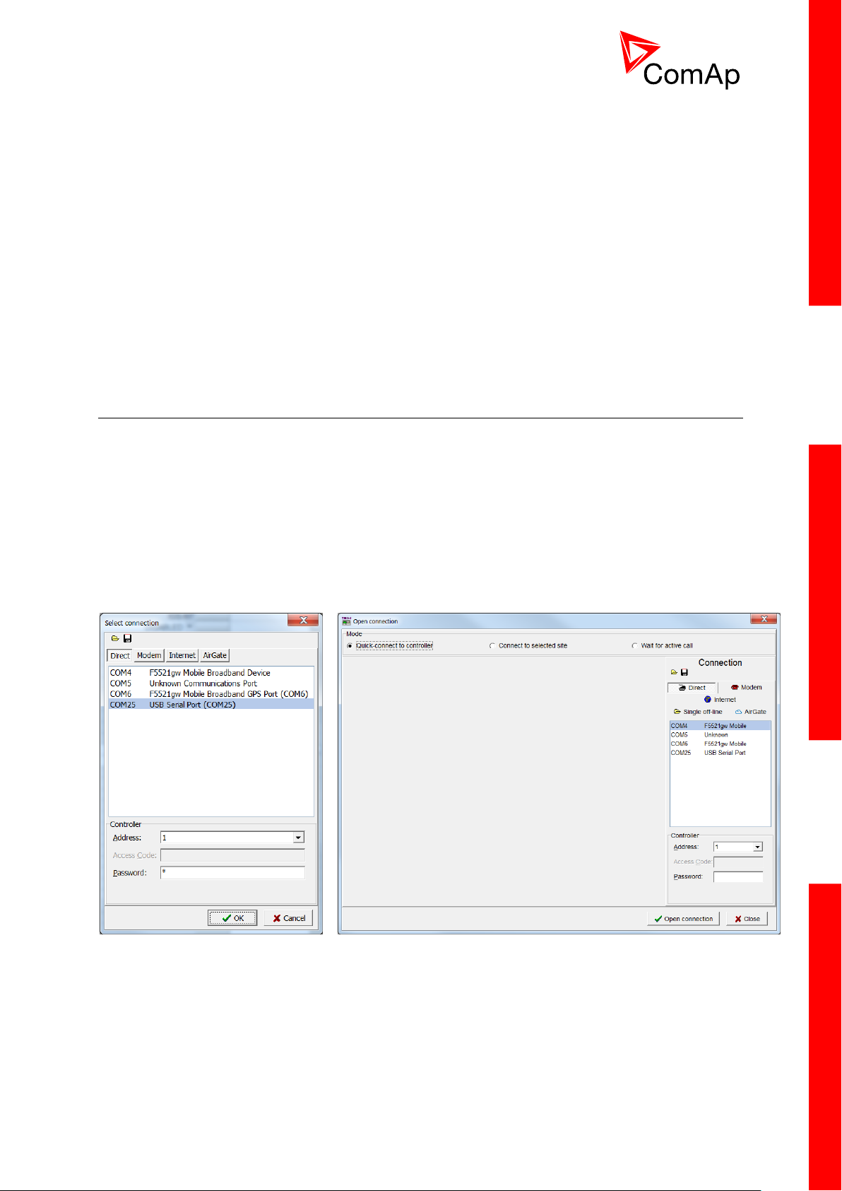
4.1.1 Direct connection
A direct connection can be realized by RS232 connection or USB connection (available on NTC
BaseBox only). Figures below illustrate the connection setting in GenConfig and InteliMonitor.
Select according COM port, adjust CAN address and enter password (optional for locked
configuration).
InteliMainsNT, SW version 3.0
InteliMains-NT-BTB-3.0-Reference Guide.pdf, ©ComAp – June 2013
Page 29
29
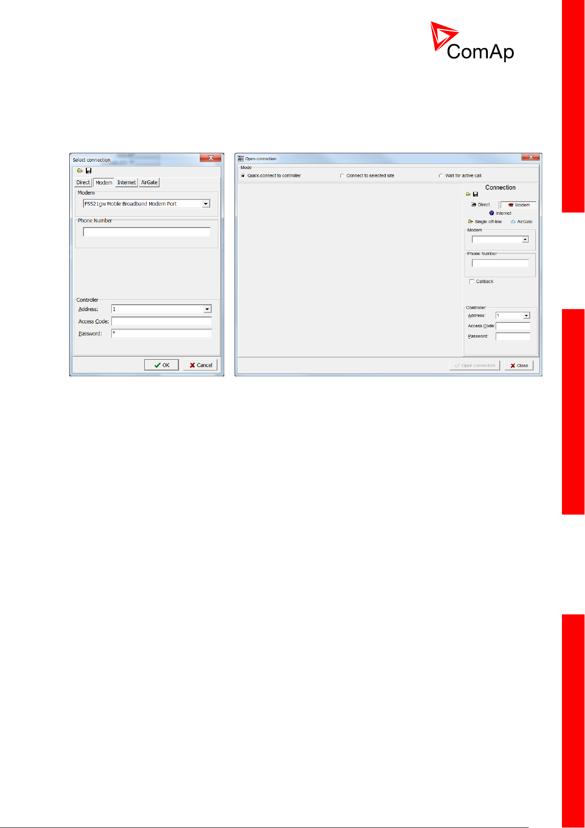
4.1.2 Modem connection
GenConfig
InteliMonitor
A modem connection can be realized by suitable modem connected to the controller. Figures below
illustrate the connection setting in GenConfig and InteliMonitor.
Select connected modem, adjust Phone number and enter CAN address and enter correct
Access Code for remote connection. Enter password (optional for locked configuration).
It is possible to adjust number of rings before the controller accepts the connection from modem – use
Comms settings:NumberRings AA.
InteliMainsNT, SW version 3.0
InteliMains-NT-BTB-3.0-Reference Guide.pdf, ©ComAp – June 2013
Page 30
30
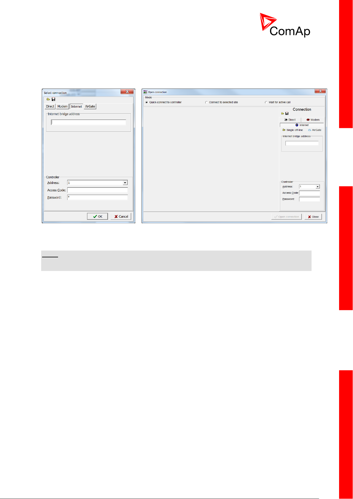
4.1.3 Internet connection
GenConfig
InteliMonitor
Internet (Ethernet) connection can be used directly in NTC BaseBox version of the controller. For
connection to other versions, use IntenetBridge-NT device. Figures below illustrate the connection
setting in GenConfig and InteliMonitor.
Adjust IP address of the controller (InternetBridge) you want to connect to. Select CAN address of the
controller. Enter Access Code for remote connection. Enter password (optional for locked
configuration).
NOTE:
The controller must have public IP address or it must be reachable for connection in the specific
network.
InteliMainsNT, SW version 3.0
InteliMains-NT-BTB-3.0-Reference Guide.pdf, ©ComAp – June 2013
Page 31

31
4.1.4 Airgate connection
GenConfig
InteliMonitor
AirGate connection can be used directly in NTC BaseBox version of the controller. For connection to
other versions, use IntenetBridge-NT device. Figures below illustrate the connection setting in
GenConfig and InteliMonitor.
Enter AirGate address of a server with AirGate service (currently airgate.comap.cz). Select CAN
address of the controller you want to connect to. Enter AirGate ID of the controller (InternetBridge) you
want to connect to (AirGate ID is assigned automatically if the controller is properly connected to the
Internet and corresponding AirGate setting is enabled. You can find AirGate ID in controller values.).
Enter Access Code for remote connection. Enter password (optional for locked configuration).
NOTE:
What is AirGate service? AirGate is a service provided for free by
ComAp which allows users to connect to controllers even though they
are not assigned public IP address or if there are behind corporate
firewalls. Controller connects to the AirGate server (secure and fast
server located in Central Europe) and obtains AirGate ID (used in the
connection, see above). Then it communicates with the server on a
secure line and any user that know AirGate ID and access code for
that particular controller can connect from anywhere (Internet access
needed) to the controller and monitor and control it.
InteliMainsNT, SW version 3.0
InteliMains-NT-BTB-3.0-Reference Guide.pdf, ©ComAp – June 2013
Page 32

32
4.1.5 Connection to multiple controllers
Direct multiple connection
Internet multiple connection (use Internet Bridges IPs for connection to NTC BaseBox
controllers as well
Airgate multiple connection (fill in AirGate IDs for each controller, when using InternetBridge
fill in InternetBridge AirGate ID for each controller)
Connection to multiple controller is available in InteliMonitor. It is possible to connect to multiple
controller using Direct connection to I-LB+, using Internet connection to NTC BaseBox controllers or to
InternetBridge, using modem connection capable of multiple connections or AirGate connection to
multiple NTC BaseBox controllers or to IntenetBridge.
InteliMainsNT, SW version 3.0
InteliMains-NT-BTB-3.0-Reference Guide.pdf, ©ComAp – June 2013
Page 33

33
4.2 Modification of configuration, setpoints etc.
For full configuration of controller configuration use GenConfig. You may open archive prepared for
specific application and upload it to the controller. You may also change:
Controller type (Modules tab)
Extension modules (Modules tab)
Binary Input and Output logical functions and protections (I/O tab)
Analog input sensor type, logical functions and protections (I/O tab)
Analog output function, conversion, normalization, resolution (I/O tab)
Setpoints and password level for particular setpoint (Setpoints tab)
Commands password protection (Commands tab)
Prepare custom protections (Protections tab)
Modify History data selection (History tab)
Prepare custom user sensor characteristics (User Sensor tab)
Modify languages settings (Languages tab)
Translate corresponding names to other language prepared in Languages tab (Translator tab)
Prepare complex logical functions with built-in PLC functions (PLC Editor tab)
Modify screens for InteliVision 5 and 8 (Screen Editor tab)
Review and modify assigned logical binary functions (LBI tab)
Review and modify assigned logical analog functions (LAI tab)
Select power format, rename Pulse counters and Remote switches (Miscellaneous tab)
CAUTION!
Do not forget that changes in GenConfig are not sent to the controller unless you write them to the
controller.
In InteliMonitor it is possible to configure:
Setpoints (multiple setpoint configuration in several controllers at once)
Set/Reset statistics
Administrate users and their rights
CAUTION!
Do not forget that all changes in InteliMonitor are sent to the connected controller and controller
immediately acts on it. Do not change CAN address of the controller or connection is lost and need to
be re-established with new CAN address.
InteliMainsNT, SW version 3.0
InteliMains-NT-BTB-3.0-Reference Guide.pdf, ©ComAp – June 2013
Page 34

34
4.3 Programming of a controller
4.3.1 Standard programming
For programming GenConfig is used. Select correct connection mode and then select the following
option:
You may use “FW upgrade (from default configuration)” (this will overwrite all of the settings in the
controller with default settings. If you need to upgrade firmware from existing configuration, select “FW
upgrade (from existing configuration)”. This function will automatically open wizard which will help you
update the existing configuration to be compatible with the newly selected firmware.
4.3.2 Programming of non-responsive controller
If the controller does not contain valid firmware, new firmware cannot be programmed in the standard
way. This situation can occur if the connection between the PC and the controller was interrupted e.g.
during a previous firmware upgrade. In such case the controller may have a blank display or
connection to InteliVision may not be established and it does not communicate with the PC. The bootjumper must be used to get valid firmware into the controller.
Connect proper cable for programming (use RS232 port).
Open GenConfig and select “FW upgrade (default configuration)”
From the following table select FW that is required or click open and browse your files to find
firmware in non-default location
InteliMainsNT, SW version 3.0
InteliMains-NT-BTB-3.0-Reference Guide.pdf, ©ComAp – June 2013
Page 35

35
Click OK
Wait until the connection times out and following dialog appears
Follow the instructions and then click OK (information regarding the location of boot jumper
can be found in section 3.1.4 (IM-NT-GC) or 3.2.4 (IM-NT-BB and IM-NTC-BB)
Programming starts momentarily
When the programming is done following dialog appears
Follow the instructions and press OK. Following diagram will appear and programming is done
InteliMainsNT, SW version 3.0
InteliMains-NT-BTB-3.0-Reference Guide.pdf, ©ComAp – June 2013
Page 36

36
Additional dialog warns you that the setpoints may have improper values. Change the
configuration in normal way.
InteliMainsNT, SW version 3.0
InteliMains-NT-BTB-3.0-Reference Guide.pdf, ©ComAp – June 2013
Page 37

37
4.4 Changing the language
This portion of instructions is dedicated to the InteliMains-NT-GC
controller with built-in display. If you have BaseBox type of the
controller (without the built-in display), please refer to the section
4.4.2.
This portion of instructions is dedicated to the InteliMains-NT-
BaseBox and InteliMains-NTC-BaseBox controllers without built-in
display. If you have version with built-in display of the controller,
please refer to the section 4.4.2.
There is step-by-step guide in GenConfig help available for the Languages and Translator tabs which
contains all the information on how to prepare new languages in the configuration (press F1 in
Languages or Translator tab or go to Help->GenConfig Help and locate corresponding chapters).
4.4.1 Selection of the language in InteliMains-NT GC
Selection of the language can be either done by Binary Input selection (please refer to the section
Functions description) or by selecting the language through the menu of built-in display. To select the
language go to main menu and scroll down. Select “Languages” by pressing Enter. There is complete
selection of languages configured in the controller. Using arrows select the preferred language and
press Enter to confirm. Display reboots (controller itself remains fully functional) and new language is
used.
HINT
If you need to use graphical language you may need to upload correct set of characters into the
controller. By default Chinese character set is uploaded in the controller. If you need to use for
example Korean characters (Hangul), in GenConfig select following menu while connected to the
controller: File -> Firmware upgrade and Cloning -> Display GC font change / FW upgrade. GenConfig
connects to the controller and new fonts may be uploaded to the controller as well as new firmware for
the built-in display.
NOTE
If you are using InteliVision 5, InteliVision 8 or InteliVision 17 Touch with the GC type of the controller
please refer also to the chapter 4.4.2 for more information on how to change language in the
InteliVision.
4.4.2 Selection of the language in InteliMains-NT(C)-BaseBox
If using BaseBox version of the controller you may use InteliVision 5, InteliVision 8 or InteliVision 17
Touch. If you need to use for some reason IG or IS-Display please refer to the chapter 4.4.1 for the
instructions regarding built-in display which works the same as the external displays.
InteliMainsNT, SW version 3.0
InteliMains-NT-BTB-3.0-Reference Guide.pdf, ©ComAp – June 2013
Page 38

38
For InteliVision 5 an 8 go to main menu and select Help/Others and Languages. Scroll up and down
and select preferred langugue. Confirm by pressing enter.
If you are using InteliVision 17, it is running standard InteliMonitor software. Please refer to the manual
of InteliMonitor how to change fonts in InteliMonitor and in custom SCADA.
HINT
If you need to use graphical language you may need to upload correct set of characters into the
InteliVision via controller. By default Chinese character set is uploaded in the controller. If you need to
use for example Korean characters (Hangul), in GenConfig select following menu while connected to
the controller: File -> Firmware upgrade and Cloning -> Display GC font change / FW upgrade.
GenConfig connects to the controller and new fonts may be uploaded to the controller as well as new
firmware for the built-in display.
4.5 Password management
Password management requires InteliMonitor for user names, passwords and rights modification. It
also requires GenConfig for assigning corresponding setpoints and command to correct right groups.
4.5.1 User administration
User administration is available only when logged in as an
Administrator. Once logged in select “Admin users…” as shown on
the right.
Following dialog is displayed:
Enable or disable users. Change user names and by double clicking change the access groups that
are accessible by particular user. Hold CTRL and click separate access groups to select only several
of them with no access to lower groups.
Log in as a different user to change password for that particular user.
NOTE:
Newly enabled user has always default password “0”.
InteliMainsNT, SW version 3.0
InteliMains-NT-BTB-3.0-Reference Guide.pdf, ©ComAp – June 2013
Page 39

39
4.5.2 Access group setting in GenConfig
To assign particular setpoint to access group use the following function in GenConfig (by clicking
select the correct access group).
NOTE:
Each setpoint may be assigned to only one access group. This setpoint can be changed by all users
with activated corresponding access rights.
To assign particular command to access group use the following function in GenConfig (by clicking
select the correct access group).
NOTE:
Each command may be assigned to only one access group. This command can be used by all users
with activated corresponding access rights.
4.5.3 Password break protection
Password break protection (PBP) can be adjusted to ENABLED or DISABLE by a tick box in
password management in InteliMonitor (see the figure below). Default value is ENABLED.
Warning “PassInsertBlck” is displayed in alarm list during the blocking period.
Controller does not accept attempts to insert correct or incorrect password during the blocking
period. In case of this attempt there is a message displayed in InteliMonitor, GenConfig and
InteliVision 5 and 8 which states the remaining time of blocking.
Controller is blocked for 5 minutes if there were 6 attempts to insert incorrect password. In case of
another six failed attempts (after the period of blocking elapses) the blocking period is 30, 60, 120 and
240 minutes long respectively.
InteliMainsNT, SW version 3.0
InteliMains-NT-BTB-3.0-Reference Guide.pdf, ©ComAp – June 2013
Page 40

40
History record “Incorrect password” is written after the 6
th
failed attempt to enter password (i.e. this
record is written once the PBP is activated). During the blocking no history records of inserting
incorrect or correct password are written.
Entering of passwords during the blocking period does not prolong the blocking period (passwords are
not actually entered because they are rejected by the controller at all).
When the controller is switched OFF and ON again (i.e. power down and up again) during the blocking
period, the blocking period is reset back to the full length of currently active PBP (e.g. if there is 24
minutes remaining out of 30 minutes after the controller reset there will be again 30 minutes
remaining).
After the correct password is inserted the PBP blocking period for next 6 failed attempts is reverted
back to 5 minutes.
InteliMainsNT, SW version 3.0
InteliMains-NT-BTB-3.0-Reference Guide.pdf, ©ComAp – June 2013
Page 41

41
4.6 Related tools
There are two tools available for user regarding the configuration of the controller:
Screen Editor – it can be used to modify screens in InteliVision 5 and 8
PLC Editor – it can be used to create and modify built-in PLC functions
HINT
For more information on Screen Editor use help in GenConfig (Help -> Screen Editor Help).
For more information on PLC Editor use GenConfig Reference Guide.
InteliMainsNT, SW version 3.0
InteliMains-NT-BTB-3.0-Reference Guide.pdf, ©ComAp – June 2013
Page 42

42
5 Operator guide
This portion of instructions is dedicated to the InteliMains-NT-GC
controller with built-in display. If you have BaseBox type of the
controller (without the built-in display) or you are using also
InteliVision with InteliMains-NT -GC, please refer to the section 5.2.
This portion of instructions is dedicated to the all
three types of controller with connected InteliVision
5 or 8. If you have InteliMains-NT-GC and you are
not using InteliVision 5 or 8 please refer to the
section 5.1.
5.1 IM-NT
For extensive information regarding operator control use operator guide for IM-NT.
5.2 Systems with InteliVision displays
For extensive information regarding operator control use operator guide for IGS-NT since general
functions of InteliVision displays are the same for InteliGen, InteliSys and InteliMains.
InteliMainsNT, SW version 3.0
InteliMains-NT-BTB-3.0-Reference Guide.pdf, ©ComAp – June 2013
Page 43

43
6 Firmware and Archives
InteliMains-NT-BaseBox and InteliMains-NTC-BaseBox
InteliMains-NT-GC
Since the version 3.0, controller firmware was differentiated for BaseBox type controllers and GC
(Graphical Character, with built-in display) controllers. These firmwares are compatible but their
functions differ slightly. It is not possible to upload BaseBox type firmware to GC controller and vice
versa.
6.1 BaseBox type controllers
The firmware for these controllers has specific functions available which are not available in Graphical
Character type controllers. The list of BaseBox-exclusive function is as follows:
Distributed Binary Inputs and Outputs
User MODBUS
6.2 Graphical Character type controllers
The firmware for GC controllers do not support functions described above, although it can still be used
in combination with BaseBox type controllers.
NOTE:
It is possible to use specialized InteliMains-NT firmware for InteliSys controllers. This firmware
supports all the functions mentioned above.
InteliMainsNT, SW version 3.0
InteliMains-NT-BTB-3.0-Reference Guide.pdf, ©ComAp – June 2013
Page 44

44
7 Function description
FUNCTION NAME
(ALPHABETICAL
ORDER)
BRIEF DESCRIPTION
RELATED SETPOINTS, INPUTS AND
OUTPUTS
Access locking
from various
sources
There are vast options regarding
access restrictions in the controller. It
is possible to lock:
Buttons for various commands
on the terminal.
External buttons for various
commands on binary inputs.
Built-in terminal or terminal #1 to
monitoring mode only.
External local terminal or
terminal #2 to monitoring mode
only.
All external remote terminals (PC
connection, displays on all buses
except on RS485 dedicated
port).
Local buttons
ACCESSLOCK INT
ACCESSLOCK D#2
ACCESSLOCK D#3
ACCESSLOCK EXT
FAULTRESBUTTON
HORNRESBUTTON
LCBBUTTON
Active call,
emailing and
SMS service
AA
This function allows user to choose
under which conditions active emailing
happens, what is the type of the
message and separate addresses or
numbers. Learn more about these
functions in a separate chapter.
History record
Alarm only
Warning
Breaker open
BrkOpn w/Reset
AcallCH1-Type
AcallCH2-Type
AcallCH3-Type
AcallCH1-Addr
AcallCH2-Addr
AcallCH3-Addr
ActCallAttempt
Acall+SMS lang
ISSUEACTCALLC1
ISSUEACTCALLC2
ISSUEACTCALLC3
SMTP authent
SMTP user name
SMTP password
SMTP address
Contr mailbox
Time zone
Alternative
brightness for
built-in
InteliGen
display.
It is possible to choose two different
levels of brightness and switch them with
logical binary input.
Alt brightness
i
i
7.1 Overview
HINT
There are numerous built-in functions in the controller that can be modified or combined to produce
new functions for specific uses. Note that it is not possible to describe all the combinations or
modifications in detail in this manual. Users are encouraged to find new way of how to use existing
functions to their benefit.
Click this symbol at the functions for more information on particular complex function.
InteliMainsNT, SW version 3.0
InteliMains-NT-BTB-3.0-Reference Guide.pdf, ©ComAp – June 2013
Page 45

45
FUNCTION NAME
(ALPHABETICAL
ORDER)
BRIEF DESCRIPTION
RELATED SETPOINTS, INPUTS AND
OUTPUTS
Automatic CAN
address
assignement
It is possible to leave the assignement of
CAN addresses on controllers
themselves. If the function is activated
controllers will look for possible collisions
of CAN bus communication and they will
change their addresses accordingly. This
function need to be activated or
deactivated in all controllers on CAN bus.
It is available only in some applications.
CANnegotiation
Automatic
display
backlight
timeout
It is possible to adjust timeout for
backlight of built-in display of the
controller. When using InteliVision
display the backlight timeout is adjusted
separately in the the display.
DispBaklightTO
Automatic
synchronization
AA
Controller automatically performs
synchronization sequence including
corresponding regulations to achieve
correct phase and voltage on both
synchronized sides. It possible to set
phase shift caused by transformers to be
taken into acount during synchronization.
Synchronization automatically closes
corresponding breaker if the voltages on
both sides do not differ more than
Voltage window and their phases do not
differ more than Phase window for time
equal to Dwell time. For regulation loops
functions please refer to a separate
chapter.
Voltage window
BRtoBLAngleReq
Phase window
Dwell time
Sync timeout
FORWARDSYNCHRO
REVERSESYNCHRO
IN SYNCHRONISM
Basic Voltage
and Current
settings
AA
In the controller there are many
parameters that are used for entering of
nominal values of Mains and Bus
characteristics. It also allows users to set
measurement transformers ratio and
select range of voltage measurement. All
of these parameters are crucial for the
right function of the controlle since
regulations, protections and other
function are directly dependant of these
settings. For additional information on
protections please refer to separate
chapter Protections and Alarm
Management.
VbL VT ratio
VbLinpRangeSel
VbR VT ratio
VbRinpRangeSel
BusLNomV
BusLNomVph-ph
BusRNomV
BusRNomVph-ph
Nomin current
NominBusLImp
BusLeftCTprim
BusLeftCTsec
AuxCurrCTprim
AuxCurrCTsec
Nominal freq
CAN bus
communication
mode
It is possible to change speed of
communication on CAN2 bus
(Intercontroller and Monitoring) to lower
(longer distance, limited to 8 controllers)
or to higher (shorter distance, limited to
32 controllers).
CAN bus mode
i
i
InteliMainsNT, SW version 3.0
InteliMains-NT-BTB-3.0-Reference Guide.pdf, ©ComAp – June 2013
Page 46

46
FUNCTION NAME
(ALPHABETICAL
ORDER)
BRIEF DESCRIPTION
RELATED SETPOINTS, INPUTS AND
OUTPUTS
Circuit Breaker
control
AA
Circuit Breaker control depends on many
various parameters. Please refer to a
separate chapter.
BTB CLOSE/OPEN
BTB ON COIL
BTB OFF COIL
BTB UV COIL
BTB STATUS
Circuit breaker
feedback
sensing
AA
Lear more about circuit breaker feedback
sensing in a separate chapter.
BTB FEEDBACK
BTB FDB NEG
Communication
log in controller
history
It is possible to log communication
events into the controller history (e.g.
opened new communication,
communication closed etc.).
LB/UART Log
Controller
modes of
operation
AA
Controller can be switched to several
modes of operation. It is possible to
switch modes using buttons on terminal,
using buttons in InteliMonitor, changing
of a setpoint or activation of binary inputs
for remote change of the mode of
operation. For more information on
modes of operation please refer to a
separate chapter.
ControllerMode
REMOTE OFF
REMOTE MAN
REMOTE AUT
OFF MODE
MAN MODE
AUT MODE
Controller
Redundancy
AA
It is possible to use redundant controller
which is in monitoring mode only unless
the primary controller fails. This is a
complex function and it is described in a
separate chapter.
Watched Contr
CTRLHEARTBEAT
CTRLHBEAT FD
EMERG. MANUAL
CTRLHBEAT SENS
Detection of
communication
error of
peripheral
modules
Controller detects any problems in
communication with extension modules
(it is possible to adjust corresponding
level of protection in GenConfig) and
issues alarm based on it.
PeriphCommErr
Detection of
empty CAN bus
This function can be used to detect failed
communication via CAN2 bus. If no other
controllers are found on CAN2 bus,
alarm is issued.
CAN2emptDetect
Disable Circuit
breaker
function
It is possible to disable one or both
breakers via InteliMains. Disabled circuit
breaker opens (if previously closed) and
InteliMains keeps it open under any
conditions.
BTB DISABLE
Evaluation of
CAN2
communication
collision
Controller automatically detects possible
collisions on CAN2 bus (e.g. same
shared binary outputs are broadcasted
by two controllers on one CAN bus).
SHxOcol detect
iii
i
InteliMainsNT, SW version 3.0
InteliMains-NT-BTB-3.0-Reference Guide.pdf, ©ComAp – June 2013
Page 47

47
FUNCTION NAME
(ALPHABETICAL
ORDER)
BRIEF DESCRIPTION
RELATED SETPOINTS, INPUTS AND
OUTPUTS
External values
available for
repeated writing
AA
It is not possible to repeatedly write
setpoints from external device (although
it is possible to repeatedly force different
values or continuously changing values
into setpoint because forced value is not
stored in the memory) because of
possible memory damage. If continuous
writing of some value into a setpoint from
external device is needed, External
values should be used and their value
should be subsequently forced to the
setpoint for safe operation. For detailed
guide to the usage of external value
please refer to a separate chapter.
ExtValue1deflt
ExtValue2deflt
ExtValue3deflt
ExtValue4deflt
ExtValue1LoLim
ExtValue2LoLim
ExtValue3LoLim
ExtValue4LoLim
ExtValue1HiLim
ExtValue2HiLim
ExtValue3HiLim
ExtValue4HiLim
ExtValue1 rate
ExtValue2 rate
ExtValue3 rate
ExtValue4 rate
EXTVALUE1 UP
EXTVALUE2 UP
EXTVALUE3 UP
EXTVALUE4 UP
EXTVALUE1 DOWN
EXTVALUE2 DOWN
EXTVALUE3 DOWN
EXTVALUE4 DOWN
EXTVALUE1RESET
EXTVALUE2RESET
EXTVALUE3RESET
EXTVALUE4RESET
Forcing of a
value to the
setpoint
AA
It is possible to force up to 16 different
values to one setpoint to change various
functions of the controller. Any suitable
setpoint or value can be forced into the
setpoint provided that this setpoint is
forcable. There are 16 Force value
setpoints designed just for forcing (if
correct value for forcing is not available
in any other setpoint or value). For
detailed step-by-step instruction on how
to use value forcing please refer to a
separate chapter.
Force value 1
Force value 2
Force value 3
Force value 4
Force value 5
Force value 6
Force value 7
Force value 8
Force value 9
Force value 10
Force value 11
Force value 12
Force value 13
Force value 14
Force value 15
Force value 16
FORCEVALUEIN 1
FORCEVALUEIN 2
FORCEVALUEIN 3
FORCEVALUEIN 4
FORCEVALUEIN 5
FORCEVALUEIN 6
FORCEVALUEIN 7
FORCEVALUEIN 8
FORCEVALUEIN 9
FORCEVALUEIN 10
FORCEVALUEIN 11
FORCEVALUEIN 12
FORCEVALUEIN 13
FORCEVALUEIN 14
FORCEVALUEIN 15
FORCEVALUEIN 16
Group Link
function for
complex
installations
(Bus Tie
Breaker)
AA
Group Link function enables ComAp
controllers to work independently or
together dependent on the state of a Bus
Tie Breaker. For more information refer
to the chapter Power management.
GROUPLINK
GroupLinkLeft
GroupLinkRight
History related
functions
AA
It is possible to modify history records
layout and set periodic time stamping in
history. Controller has adjustable time
and date setpoints (time is update each
second) and there is inbuilt summer time
mode function. Read about history layout
modification in separate chapter.
Time stamp act
Time Stamp Per
#SummerTimeMod
#Time
#Date
TIME STAMP ACT
iii
i
InteliMainsNT, SW version 3.0
InteliMains-NT-BTB-3.0-Reference Guide.pdf, ©ComAp – June 2013
Page 48

48
FUNCTION NAME
(ALPHABETICAL
ORDER)
BRIEF DESCRIPTION
RELATED SETPOINTS, INPUTS AND
OUTPUTS
Internet related
communication
functions
AA
It is possible to connect controllers to
Internet. AirGate function is also
available when Internet connection is
established. Active emails may be sent
upon various reasons. For more
information on these functions please
refer to a separate chapter.
IP Addr mode
IP address
Net mask
Gateway IP
ComApProtoPort
AirGate
AirGate IP
DNS IP
NumberRings AA
Language
selection
InteliMains can change language in its
built-in display as well as in attached
displayes by activation of binary inputs.
LANG SEL INT A
LANG SEL INT B
LANG SEL INT C
LANG SEL D#2 A
LANG SEL D#2 B
LANG SEL D#2 C
LANG SEL D#3 A
LANG SEL D#3 B
LANG SEL D#3 C
Load shedding
function
AA
Complex load shedding and
reconnection function is available in the
controller. It is described in the separate
chapter.
Ld shed active
Ld shed level
Ld shed delay
Ld recon level
Ld recon del
AutoLd recon
LDSHED STAGE 1
LDSHED STAGE 2
LDSHED STAGE 3
MANUALLDRECON
Mains Coupling
This function defines if Mains Coupling is
enabled via controller breaker. It should
be enabled only if two or more Mains
incommers are in phase and it is allowed
by local authorities.
Mains coupling
Measurement of
P and Q
selection
You may select the source of Mains
current measurement or disable this
measurement.
I/E-PbL meas
I/E-QbL meas
I/E-PBL
I/E-QBL
Permanent
logical 0 or 1
outputs
It is possible to use permanent logical
binary function that is always logical 0 or
logical 1. It may used for various
purposes.
LOGICAL 0
LOGICAL 1
i
i
InteliMainsNT, SW version 3.0
InteliMains-NT-BTB-3.0-Reference Guide.pdf, ©ComAp – June 2013
Page 49

49
FUNCTION NAME
(ALPHABETICAL
ORDER)
BRIEF DESCRIPTION
RELATED SETPOINTS, INPUTS AND
OUTPUTS
Power
Management
AA
Power management is a very complex
function with many settings that is used if
the gen-sets are in AUT mode of
operation (and other requirements are
fulfilled) to start and stop engines
accordingly to set parameters for more
efficient function of the system. Part of
Power Management consists of
automatic priority swapping for extended
efficiency of the system. For complete
information of all Power Management
function please refer to a separate
chapter.
#Pwr mgmt mode
#PriorAutoSwap
Priority ctrl
#SysAMFstrtDel
#SysAMFstopDel
LoadResStrt 1
LoadResStop 1
LoadResStrt 2
LoadResStop 2
LoadResStrt 3
LoadResStop 3
LoadResStrt 4
LoadResStop 4
%LdResStrt 1
%LdResStop 1
%LdResStrt 2
%LdResStop 2
%LdResStrt 3
%LdResStop 3
%LdResStrt 4
%LdResStop 4
NextStrt Del
OverldNext Del
NextStopDel
SlowStopDel
MinRunPower 1
MinRunPower 2
MinRunPower 3
RunHrsMaxDiff
PwrBandContr 1
PwrBandContr 2
PwrBandContr 3
PwrBandContr 4
PwrBnChngDlUp
PwrBnChngDlDn
LOAD RES 2
LOAD RES 3
LOAD RES 4
SYSTREADY
SYST RES OK
SYST RES 1 OK
SYST RES 2 OK
SYST RES 3 OK
SYST RES 4 OK
ALLAVAILGS RUN
ENGINES SWAPPED
Process
limitation
control
AA
This function is used to limit process (e.g.
parallel operation is not allowed). This
function is complex and it is described in
a separate chapter.
DeadBusClosing
Synchro enable
i
i
InteliMainsNT, SW version 3.0
InteliMains-NT-BTB-3.0-Reference Guide.pdf, ©ComAp – June 2013
Page 50

50
FUNCTION NAME
(ALPHABETICAL
ORDER)
BRIEF DESCRIPTION
RELATED SETPOINTS, INPUTS AND
OUTPUTS
Protections
AA
Protections in the controller are very
complex function with many settings.
Please refer to a separate chapter for
more information about protection
functions in InteliMains.
Horn Timeout
BinInp delay 1
BinInp delay 2
BinInp delay 3
ForceBlockDel1
ForceBlockDel2
ForceBlockDel3
ResetActAlarms
Force block 1
Force block 2
Force block 3
VBUSL <>
VBUSR <>
FBUSL <>
FBUSR <>
BUSL OK
BUSR OK
BUSL FAIL
BUSR FAIL
HORN
ALARM
HORN FLASHING
ALARM FLASHING
COMMON WRN
COMMON BOR
COMMON FLS
COMMON BOP
COMMON AL
COMMON HST
COMMONACTLEV 1
COMMONALLEV 1
COMMONACTLEV 2
COMMONALLEV 2
BusL2POvrldProt
OverldStrtEval
2POvrldStEvDel
BusL2Inom prot
BusL2Inom del
BusLVolt prot
BusLeft >V
BusLeft <V
BusLeft V del
BusLfreq prot
BusLeft >f
BusLeft <f
BusLeft f del
BusMeasErrLR
Pulse Counters
The controller offers up to 4 pulse
counters that can count incomming
pulses of at least 100 ms (high and low)
length with various conversion. The
counted value is stored in the controller
and can be displayed.
ConvCoefPulse1
ConvCoefPulse2
ConvCoefPulse3
ConvCoefPulse4
PULSECOUNTER 1
PULSECOUNTER 2
PULSECOUNTER 3
PULSECOUNTER 4
Regulation
functions
AA
There is whole variaty of regulation
functions in the controller. Please refer to
a separate chapter to find out more.
Freq gain
Freq int
Angle Gain
Voltage gain
Voltage Int
Remote Control
Function
AA
This particular function enables user to
close or open binary output assigned to
RemoteControl function from
InteliMonitor or via Modbus commands.
For more information please refer to a
separate chapter.
REMOTECONTROL1
REMOTECONTROL2
REMOTECONTROL3
REMOTECONTROL4
REMOTECONTROL5
REMOTECONTROL6
REMOTECONTROL7
REMOTECONTROL8
iii
InteliMainsNT, SW version 3.0
InteliMains-NT-BTB-3.0-Reference Guide.pdf, ©ComAp – June 2013
Page 51

51
FUNCTION NAME
(ALPHABETICAL
ORDER)
BRIEF DESCRIPTION
RELATED SETPOINTS, INPUTS AND
OUTPUTS
RS232 and
RS485
communication
functions
The controller has several settings
regarding RS232 and RS485 functions. It
is possible to set mode of communication
on particular port, speed of
communication and AT commands for
modem connection.
RS232(1) mode
RS232(2) mode
RS232(1)MBCSpd
RS232(2)MBCSpd
RS232(1)MdmIni
RS232(2)MdmIni
RS485(1) conv.
RS485(2) conv.
Timers
AA
Up to 16 timers are provided in the
controller (with 4 combined outputs).
They can be used to trigger various
internal functions as well as external
devices. Please refer to a separate
chapter for detailed information.
Timer channel 1
Timer channel 2
Timer channel 3
Timer channel 4
Timer channel 5
Timer channel 6
Timer channel 7
Timer channel 8
Timer channel 9
Timer channel 10
Timer channel 11
Timer channel 12
Timer channel 13
Timer channel 14
Timer channel 15
Timer channel 16
TIMERACT 1-4
TIMERACT 5-8
TIMERACT 9-12
TIMERACT 13-16
TIMERACTIVECOM
TIMER BLOCK 1
TIMER BLOCK 2
TIMER BLOCK 3
TIMER BLOCK 4
TIMER BLOCK 5
TIMER BLOCK 6
TIMER BLOCK 7
TIMER BLOCK 8
TIMER BLOCK 9
TIMER BLOCK 10
TIMER BLOCK 11
TIMER BLOCK 12
TIMER BLOCK 13
TIMER BLOCK 14
TIMER BLOCK 15
TIMER BLOCK 16
User Buttons
AA
It is possible to use up to 8 user buttons.
User buttons can be for example
assigned to software buttons in
InteliVision displays. Pressing of
corresponding button then activates the
output with function that is chosen in the
configuration. For more information on
how to use User Buttons please refer to
a separate chapter.
USER BUTTON 1
USER BUTTON 2
USER BUTTON 3
USER BUTTON 4
User
Configurable
protections
AA
There are several prepared user
configurable protections in default
archive. Please refer to a separate
chapter for complex step-by-step
instructions on user configurable
protections.
Batt >V
Batt <V
Batt volt del
BusL V unbal
BusL Vunb del
BusL I unbal
BusL I unb del
iii
InteliMainsNT, SW version 3.0
InteliMains-NT-BTB-3.0-Reference Guide.pdf, ©ComAp – June 2013
Page 52

52
FUNCTION NAME
(ALPHABETICAL
ORDER)
BRIEF DESCRIPTION
RELATED SETPOINTS, INPUTS AND
OUTPUTS
Variable
connection of
devices on CAN
bus
It is possible to select number and type
of devices connected on CAN2 bus
(MODEM: I-LB+ or OTHER: InteliVision,
I-RD). CAN addresses 123 and 124 are
always dedicated to connection of
OTHER devices (e.g. InteliVision 5
CAN). Using two setpoints dedicated to
this function, it is possible to choose if
addresses 122 and 125 are used for
communication by OTHER devices or in
MODEM mode (i.e. prepared for I-LB+ or
IB-NT connection).
CANAddrSwitch1
CANAddrSwitch2
Voltage
protections
mode Ph-N or
Ph-Ph
AA
In the controller it is possible to select
whether fixed protections are based on
measured Ph-N voltage or on measured
Ph-Ph voltage. For more information of
fixed protections please refer to the
separate chapter Protections and Alarm
management.
FixVoltProtSelect
Wrong Phases
sequence
Controller automatically detects if phases
measurement is connected in wrong
sequence (note that the wrong sequence
is not detected if the phases are just
rotated, i.e. L2-L3-L1)
WRONGPHSEQ
i
7.2 Modes
7.2.1 OFF mode
All regulations are switched off.
Switching to OFF mode causes opening of BTB regardless of the settings.
7.2.2 MAN mode
It is possible to close/open BTB manually under supervision of IM-NT controller (automatic
synchronization is started if there are voltages on both sides).
Pressing BTB ON/OFF button closes/opens BTB if it is allowed by
setpoints Process control:Synchro enable, Mains coupling, DeadBusClosing
binary input BTB DISABLE
NOTE:
It is possible to close BTB in MAN mode without voltage on bus left and bus right based on setting of
DeadBusClosing setpoint.
7.2.3 AUT mode
Controller closes automatically BTB if
InteliMainsNT, SW version 3.0
InteliMains-NT-BTB-3.0-Reference Guide.pdf, ©ComAp – June 2013
Page 53

53
bus voltages are within the limits (Sync ctrl:Phase window, Voltage window)
SYNCHRO ENABLE
DEADBUSCLOSING
SHORT DESCRIPTION
NONE
It is not possible to synchronize Buses together if there are
healthy voltages on both buses
L->R
It is possible to synchronize Buses together if there are healthy
voltages on both buses and the Left Bus is available for
synchronizing (i.e. the synchronization will not be successful if
Left Bus is connected to the Mains)
R->L
It is possible to synchronize Buses together if there are healthy
voltages on both buses and the Right Bus is available for
synchronizing (i.e. the synchronization will not be successful if
Right Bus is connected to the Mains)
BOTH
It is possible to synchronize Buses together if there are healthy
voltages on both buses (the controller will synchronize Left Bus
to the Right Bus if the Left Bus is not connected to the Mains, if
Left Bus is connected to the Mains, controller synchronizes Right
Bus to the Left Bus)
NONE
It is not possible to close the breaker if there is healthy voltage
on one of the Buses and there is no voltage on the other one or
if there is no voltage on both Buses
L->R
It is possible to close the breaker if there is healthy voltage on
the Left Bus and there is no voltage on the Right Bus
R->L
It is possible to close the breaker if there is healthy voltage on
the Right Bus and there is no voltage on the Left Bus
BOTH
It is possible to close the breaker if there is healthy voltage on
one of the Buses and there is no voltage on the other one
there is voltage on both, one or none of the buses and closing to dead bus is enabled by
Process control:DeadBusClosing (refer to this setpoint in Context Help or in APPENDIX of
this document to get more information)
binary input BTB DISABLE is not closed
it is enabled by setting of Process control:Synchro enable, Mains coupling setpoints
NOTE:
If voltage on both left and right buses disappears, the BTB is automatically opened regardless of
Process control:DeadBusClosing.
After the BTB is closed, InteliMains-BTB deactivates all regulation loops and they are taken over by
the IM-M(G)CB.
7.3 Process Limitation
It is possible to influence the behavior of the controller in MAN and AUT mode and limit the process.
There are many possibilities but only some of them allow valid function of the breaker (e.g. the breaker
will not be able to close if Synchronization is set to NONE and DeadBusClosing set to NONE as well).
Process Limitation is also influenced by the setpoint ProcessControl:Mains coupling, so even though
it is possible to e.g. synchronize two Buses together, controller will block this function if both Buses are
connected to Mains incomers and Mains coupling is DISABLED.
InteliMainsNT, SW version 3.0
InteliMains-NT-BTB-3.0-Reference Guide.pdf, ©ComAp – June 2013
Page 54

54
7.4 Power management
Group 1 Group 2
Group 3
Group 4
Group 1 Group 2
Group 3
Group 4
Group 1 Group 2
Group 3
Group 4
7.4.1 Standard Power management
Standart Power management setpoints and values are included in BTB application for compatibility
purposes and InteliMains-BTB does not play active role in power management.
Nonetheless, InteliMains-BTB plays crucial role in Control Group functions – it performs
synchronization of the Control Groups together (based on Process Limitation). In connection to this,
GroupLink function may be performed by InteliMains-BTB. This function broadcasts information about
the connection of two groups together via CAN to all other controllers. Two connected groups are
considered as one new group by all other controllers. The diagram below shows how the principle of
the function works. Once Group 3 is connected to the Group 2, it is also considered connected to the
Group 1 because the connection of Group 1 and Group 2 is also broadcasted on the CAN.
7.4.2 Load shedding
Load shedding is a function that automatically disconnects and reconnects various load depending on
several user defined parameters.
Important setpoints: all setpoints in group Load shedding
The load shedding function is active in all controller modes except OFF. Load shedding works based
on Load import value.
Load shedding has three steps and each step is linked with its own Load shed binary output
(LDSHED STAGE X). There is only one load shed level and delay for all three steps as well as recon
level and delay (setpoints in Load shedding group Ld shed level, Ld shed delay, Ld recon level, Ld
recon delay). Load shed can only move from one step to the next, e.g. “No LoadShed” to “LdShed
stage 1” to “LdShed stage 2” to “LdShed stage 3” and vice versa.
If manual reconnection of the load is desired, the Load shedding:AutoLd recon setpoint needs to be
disabled (DISABLED) and the MANUALLDRECON binary input needs to be configured.
Rising edge on this input resets the controller to a lower stage, but only if the load is under the Ld
recon level for Ld recon delay at that moment.
Depending on Load shedding:Ld shed active setting load shedding is never active (DISABLE) or
active all the time (ENABLE).
NOTE:
If no Load Shedding outputs are configured, there is no record to history and no screen timer
indication of the activity of this function.
InteliMainsNT, SW version 3.0
InteliMains-NT-BTB-3.0-Reference Guide.pdf, ©ComAp – June 2013
Page 55

55
Ld shed delay
Ld shed delay
Ld shed delay
BO LdShed stage 1
BO LdShed stage 2
BO LdShed stage 3
Ld shed level
Mains import or
gen-sets power
Time
Ld recon delay
Ld recon delay
Ld recon delay
BO LdShed stage 1
BO LdShed stage 2
BO LdShed stage 3
Ld recon level
Time
Mains import or
gen-sets power
Ld recon delay
Ld recon delay
Ld recon delay
BO LdShed stage 1
BO LdShed stage 2
BO LdShed stage 3
Ld recon level
Mains import or
gen-sets power
Time
BI ManualLdRecon
Figure: Examples of load shedding and load reconnection (load shed, load recon, manual load recon)
7.5 Remote Alarm Messaging
It is possible to use up to five channels for Active Call, Email and SMS upon defined type of Alarm. It
is possible to define protection type for all ENABLED channels to react. All the possibilities in
InteliMains are: History record, Alarm only, Warning, Breaker open and BrkOpen w/Reset. Find more
information about alarm types in the chapter Protections and alarm management.
7.5.1 Communication Types for Remote Alarm Messaging
Below there all types of communication available for each Active Call channel.
DATA-ANA: This option sends a complete archive to the recipient's PC via analog modem. An analog
modem must be connected either to one of controller COM ports or to one of I-LB modules connected
to the controller via CAN2 bus. The channel address must contain complete telephone number of the
recipient's PC where InteliMonitor is running in Active call receiving mode.
InteliMainsNT, SW version 3.0
InteliMains-NT-BTB-3.0-Reference Guide.pdf, ©ComAp – June 2013
Page 56

56
DATA-GSM: This option sends a complete archive to the recipient's PC via GSM modem. A GSM
modem with activated CSD data transfers must be connected either to one of controller COM ports or
to one of I-LB modules connected to the controller via CAN2 bus. The channel address must contain
complete telephone number of the recipient's PC where InteliMonitor is running in Active call receiving
mode.
DATA-ISDN: This option sends a complete archive to the recipient's PC via ISDN modem. An ISDN
modem must be connected either to one of controller COM ports or to one of I-LB modules connected
to the controller via CAN2 bus. The channel address must contain complete telephone number of the
recipient's PC where InteliMonitor is running in Active call receiving mode.
DATA-CDMA: This option sends a complete archive to the recipient's PC via CDMA modem. A CDMA
modem must be connected either to one of controller COM ports or to one of I-LB modules connected
to the controller via CAN2 bus. The local CDMA network must allow point-to-point data transfers. The
channel address must contain complete telephone number of the recipient's PC where InteliMonitor is
running in Active call receiving mode.
SMS-GSM: This option sends a short text message (SMS) containing the actual Alarmlist contents to
the recipient's mobile phone via the GSM modem. The channel address must contain complete
telephone number of the recipient's mobile phone.
SMS-CDMA: This option sends a short text message (SMS) containing the actual Alarmlist contents
to the recipient's mobile phone via the CDMA modem. The channel address must contain complete
telephone number of the recipient's mobile phone.
IB-E-MAIL: This option sends an e-mail containing the actual Alarmlist contents and latest 20 history
records (only date, time, reason) to the recipient's mailbox via the IB-COM module or IG-IB module.
The channel address must contain valid e-mail address of the recipient.
NOTE:
The SMTP settings (SMTP authent,SMTP user name, SMTP password, SMTP address, Contr
mailbox) must be properly adjusted for sending e-mails.
7.5.2 Example of setting
There is an example of setting of Remote Alarm Messaging. In this case active calls we be triggered
on Breaker open and BrkOpen w/Reset alarms. Message is sent via email to
emailAddress@domain.com (Channel 1 – available for NTC controller or with any controller with
connected IB-NT or I-LB+), archive is sent via ISDN modem to the number +111222333444 (Channel
2) and SMS is sent to the number +999111333555 (Channel 3).
It is also possible to adjust number of attempts that controller performs in case of not successful Active
Call – Comms settings:ActCallAttempt. The language of messages can be changed –
Comms settings:Acall+SMS lang (use Translator and Languages tabs in GenConfig to adjust
languages).
InteliMainsNT, SW version 3.0
InteliMains-NT-BTB-3.0-Reference Guide.pdf, ©ComAp – June 2013
Page 57

57
7.6 Controller Redundancy
VPIO
VPI
VPO
CtrlHBeat FD
Emerg. manual
CAN
LOG BOUT
LOG BIN
Watched contr = X
Setpoint
Emerg. manual
LOG BIN
CAN
BOUT
BIN
LOG BIN
MAIN CONTROLLER
REDUNDANT CONTROLLER
Contr. Address = X
Setpoint
Redundant system is a general term for applications where there are two controllers at each gen-set.
One is the main controller, which controls the gen-set in normal conditions, the other is the redundant
controller, which takes over the control when the main controller fails. Both controllers have identical
firmware and most of the configuration and setpoints. Only several things need to be
adjusted/configured differently because of the rendundancy function itself.
CAUTION!
If there are shared binary or analog outputs used on InteliMains (e.g. for system start/stop), it is
necessary to prepare the configuration in the way so each controller uses binary or analog output set
with different address. Configuration in gen-set controllers then needs to be altered so it can receive
signals from both InteliMains controller (e.g. using built-in PLC functions).
7.6.1 Redundant systems using binary signals
It is not possible to use this redundancy system since correct function of InteliMains depends on CAN
bus communication and thus CAN redundancy should be always used.
7.6.2 Redundant systems using CAN bus
This system uses the CAN bus for detection whether the main controller is operational or not. If the
redundant controller has not received two consequent messages from the main one (~100ms) it will
take over the system control - it activates the binary output CTRLHBEAT FD, which has to be wired in
such a way, that it disconnects the dead main controller from the control, connects the redundancy
controller instead and activates it by deactivation of the binary input EMERG. MANUAL.
As there can be up to 16 pairs of controllers at the CAN bus it is necessary to select which main
controller (address) belongs to which redundant one. The setpoint ProcessControl:Watched Contr is
used for this purpose. It must be adjusted to address of the respective main controller in each
redundant controller and it must be adjusted to 0 in each main controller.
CAUTION!
Correct wiring of all inputs and outputs that should be used both by the main and the redundant
controller needs to be done. Please refer to the corresponding chapter for wiring of binary inputs and
outputs.
Do not use Shared Binary Inputs/Outputs for CTRLHBEAT FD -> EMERG.MANUAL connection since the
failed controller may not interpret it correctly!
Figure: Example of redundancy function
InteliMainsNT, SW version 3.0
InteliMains-NT-BTB-3.0-Reference Guide.pdf, ©ComAp – June 2013
Page 58

58
In the figure above the signal of logical function CtrlHBeat FD is used to disable the main controller if it
Add or remove Force value
Change position of Force value functions (priority)
Change the name of the source setpoint
(available only for Force value 1-16 setpoints)
Select the value that should be forced (i.e.
the value of the particular setpoint)
Rename binary input that
triggers the forcing
ID of binary input
(1 for ForceValueIn 1 etc.)
Select source setpoint or value
is lost from CAN bus or CAN bus communication from that controller becomes erratic. It is used also
to disable the redundant controller when the communication on CAN bus is alright (it is negated). For
more information on Virtual Binary Inputs and Outputs (VPIO) please refer to the chapter about
Shared Binary Inputs and Outputs and Virtual Binary Inputs and Outputs.
NOTE:
Use pulse signals for control of circuit breakers. LCB ON COIL and LCB OFF COIL should be used to
prevent sudden opening for a short period of time when the controller fails and to ensure proper
function of redundancy.
7.7 Force value – step by step guide
In this chapter there is complete step by step guide which shows how to use Force value function of
the controller.
Forcing of values is used to change particular setpoint temporarily by activation of related Binary Input.
This is used to change function of controller under given conditions (e.g. there are two different
periods during the day when Export limit given by distribution network is required or not).
WARNING!
Setpoints must not be written continuously (e.g. via Modbus connection)! If continuous change of
setpoints is required, combination of External values and Force value function needs to be used. The
memory that holds setpoints is designed for up to 105 writings. Than memory may be damaged!
Setpoints that are available for forcing may be identified by Force value button on the right side in
GenConfig (see the figure below).
When the button is clicked, Force value dialog appears.
InteliMainsNT, SW version 3.0
InteliMains-NT-BTB-3.0-Reference Guide.pdf, ©ComAp – June 2013
Page 59

59
For example if we add Force value:Force value 1 to be forced to ProcessControl:Export limit as
FREQUENCY LOOP
The frequency loop is active in the following situations dependending on the
application. For more information see the table below.
APPLICATION
FREQ GAIN AND FREQ INT SETPOINTS ARE ACTIVE DURING:
BTB
synchronization between “left” and “right” buses
See also setpoints: Sync ctrl:Freq gain and Sync ctrl:Freq int
When the Sync ctrl:Freq gain is set to zero, this control loop is switched OFF.
ANGLE LOOP
The differential angle control loop is active during the synchronization (see
Frequency loop above) when the "near to zero" slip frequency has been
successfuly achieved and then the differential angle between bus and mains
voltage shall be controlled to the value adjusted by the
setpoint Sync ctrl:BRtoBLAngleReq.
See also setpoint: Sync ctrl:Angle Gain
VOLTAGE LOOP
The Voltage loop is active in the following situations dependending on the
application. For more information see the table below.
value 0 (DISABLED) by Binary Input FORCEVALUEIN 1 we can change the function of Export limit from
ENABLED to DISABLED by activation of FORCEVALUEIN 1. It is possible to rename the setpoint to e.g.
Force value:ExportDisabled and Binary Input as well to e.g. DISABLEEXPLIM. The function will not
change (only the corresponding names).
It is possible to use several force value functions for one setpoint. If more than one forcing Binary
Input is active, the one with the highest position (lowest number in the Force value dialog) is used.
It is possible as well to use one Binary Input to force multiple setpoints (e.g. in case of complex
function change).
NOTE:
It is possible only to force value or setpoint in other setpoint if their dimension and range are the same
(e.g. only value with dimension in hours and which is Integer 16 to a setpoint with dimension hours
and which is as well Integer 16). You may use PLC block Convert to change the dimension and range
if needed.
7.8 Regulation loops
There are following regulation loops built-in in the controller. All of them are PI type except angle loop,
which is P type.
InteliMainsNT, SW version 3.0
InteliMains-NT-BTB-3.0-Reference Guide.pdf, ©ComAp – June 2013
Page 60

60
APPLICATION
VOLTAGE GAIN AND VOLTAGE INT SETPOINTS ARE ACTIVE DURING:
BTB
synchronization between “left” and “right” buses
See also setpoints: Volt ctrl:Voltage gain and Volt ctrl:Voltage Int
When the Voltage gain is set to zero, this control loop is switched OFF.
7.8.1 PI regulation adjustment
The regulation loops have two adjustable factors: P-factor and I-factor (except angle regulation loop,
which has P-factor only). The P-factor (gain) influences the stability and overshoot of the regulation
loop and the I-factor influences the steady-state error as well as the settling time. See the picture
below for typical responses of a PI regulation loop.
Figure: Typical responses of a PI regulator
For manual tunning of a control loop use following method:
1. Set both the I-factor and P-factor to 0.
2. Increase the P-factor slightly until the system starts to oscillate.
3. Adjust the P-factor back to approx. one half of the value where the oscillations started.
4. Increase the I-factor slightly to achieve optimal resulting response.
NOTE:
It may be helpful to disable issuing the breaker close command when adjusting synchronization loops.
Adjust the setpoint Phase window to 0 to disable it. Adjust the setpoint back to it's original value after
the adjustment is finished.
CAUTION!
Be ready to press emergency stop button in case the regulation loop would start to behave
unacceptable while it is beeing adjusted.
InteliMainsNT, SW version 3.0
InteliMains-NT-BTB-3.0-Reference Guide.pdf, ©ComAp – June 2013
Page 61

61
7.9 Values for continuous writing from external sources
ONCE
This is a single shot mode. The timer will be activated only once at preset
date/time for preset duration.
DAILY
The timer is activated every "x-th" day. The day period "x" is adjustable.
Weekends can be excluded. E.g. the timer can be adjusted to every 2nd day
excluding saturdays and sundays.
WEEKLY
The timer is activated every "x-th" week on selected weekdays. The week period
"x" is adjustable. E.g. the timer can be adjusted to every 2nd week on monday
and friday.
This function is especially designed for continuous writing of setpoints from external sources (e.g. via
Modbus connection).
WARNING!
Setpoints must not be written continuously (e.g. via Modbus connection)! If continuous change of
setpoints is required, combination of External values and Force value function needs to be used. The
memory that holds setpoints is designed for up to 105 writings. Than memory may be damaged!
It is possible to use up to four different External values for continuous writing from external sources.
The values are adjusted by setpoints in Force value group. Default (also initial) value may be
adjusted, rate of change of ExtValueX (by Binary Inputs EXTVALUEX UP and EXTVALUEX DOWN) can be
adjusted as well as high and low limit of the value.
There are two way, how to adjust External values. One is using Binary Inputs mentioned above.
Second one is to write the value directly using e.g. Modbus. External values then may be converted
using PLC block convert and force into setpoint which is then continuously forced (note: NOT
WRITTEN) by the value of ExtValueX. This way internal memory is safe and no damage may occur.
External values are reverted back to their default (initial) value (given by corresponding setpoint) when
Binary Input for their reset is active (and they change to the previous value after Binary Input
deactivates). When the Binary Input is active the External value cannot be changed by Modbus writing
or by using Binary Inputs for up and down value.
NOTE:
External values are not available for external writing when any Binary Input (up, down or reset) related
to them is active.
Note also that when the controller is reset (powered down and up again), all external values are
reverted back to their default (initial) values.
HINT
For information on how to write (or read) objects from controller via Modbus, please refer to the latest
Communication guide for InteliGen and InteliSys.
7.10 General Purpose Timers
There is 16 general-purpose timers in the controller, each 4 of them are joined together to one output.
That means there are 4 fully independent timer blocks including 4 timer channels each. The combined
outputs from the timer blocks are TIMERACT 1-4, TIMERACT 5-8, TIMERACT 9-12 AND TIMERACT 13-16.
The timers are intended for scheduling of any operations such as e.g. periodic tests of the gen-set,
scheduled transfer of the load to the gen-set prior to an expected disconection of the mains etc. Each
timer channel can be activated only once within a single day. The activation time and duration of each
channel is adjustable (both as hh:mm).
7.10.1 Timer modes
Available modes of each timer:
InteliMainsNT, SW version 3.0
InteliMains-NT-BTB-3.0-Reference Guide.pdf, ©ComAp – June 2013
Page 62

62
MONTHLY
The timer is activated every "x-th" month on the selected day. The requested day
can be selected either as "y-th" day in the month or as "y-th" weekday in the
month. E.g. the timer can be adjusted to every 1st month on 1st tuesday.
SHORT PERIOD
The timer is repeated with adjusted period (hh:mm). The timer duration is
included in the preriod.
The mode of each timer channel is adjusted by an assigned setpoint. The setpoints are located int
the Timer settings group and can be adjusted via InteliMonitor and GenConfig.
Figure: Principial scheme of one block containing 4 timers
EXAMPLE:
Below is an example how to use the timers for periodic tests of the gen-set performed every sunday
with duration of 30 minutes and also for scheduled transfer of the load before expected mains failure
announced by the local electricity distribution company to 1.5.2010 from 01:00 to 04:00.
1. The output TIMERACT 1-4 is configured internally in GenConfig (LBI tab) to the logical binary
inputs REMOTE TEST and TEST ON LOAD.
2. The setpoint Timer settings:TimerChannel 1 is adjusted to "repeated" mode, "weekly" period,
only sundays, starting date/time next sunday at 0:00, timer duration 0:30 min.
3. The setpoint Timer settings:TimerChannel 2 is adjusted to "once" mode, starting date/time
1.5.2010 at 01:00, timer duration 3:00 hrs.
InteliMainsNT, SW version 3.0
InteliMains-NT-BTB-3.0-Reference Guide.pdf, ©ComAp – June 2013
Page 63

63
7.11 History Related functions
7.11.1 History Records Adjustment
It is possible to change History records content. Each record contains date, time and cause of the
record as obligatory columns. The rest of columns are configurable.
The history record structure has two parts. The upper part is so-called fast and is written into the
history memory immediately in the moment when the written event occurs. The rest of the record may
be written with a delay max. 100ms. The fast part is intended for fast changing values as e.g. currents,
voltages or power. The parts are separated by a line in the record content list.
1. Values selection tree
2. Buttons for adding/removing values into/from the record structure
3. Buttons for ordering of the values in the record structure
4. Fast history separator. The fast part is located above the separator
5. Estimated number of records depending on record size
6. Record capacity usage indicator
NOTE:
Values that are displayed in green color are recomended to be placed in the fast part.
If the checkbox Add modules to history automatically.. in the Modules tab is checked then all values of
a module are automatically added into the history record when the module is inserted into the
configuration.
7.11.2 Time Stamp function
The controller allows user to define when the history records are written even though there is no other
reason for history record (so called Time Stamp).
It is possible to disable time stamping function (for example when time stamping is not needed and
just floods the history). It may be conditioned by activation of logical Binary Input function
(TIME STAMP ACT) or it may be enabled always.
Period of time stamping may be adjusted from 1 to 240 minutes.
NOTE:
Beware of History flooding by to many Time Stamps (vital information may be overwritten).
7.11.3 Time and Date Intercontroller Sharing
Time and Date are used mainly for History records. These values are shared between controllers that
are connected to CAN. When the value is changed in one controller, it sends its new value to all other
controllers that are connected to the same CAN bus and they update their time and date values and
setpoints accordingly.
InteliMainsNT, SW version 3.0
InteliMains-NT-BTB-3.0-Reference Guide.pdf, ©ComAp – June 2013
Page 64

64
7.11.4 Summer Time Mode
Selects which button is this function mapped to
(0 – first button, 1 – second button and so on)
Choose UserButton index and
its function (ON/OFF etc.)
Choose which colour will be
available for this button
Select which condition triggers
which coulour
Adjust text for the button
when it is active or inactive
ON
Pressing the button changes the state of log. Binary Output USER BUTTON X to
closed. When the output is closed and the button is pressed state is not changed.
OFF
Pressing the button changes the state of log. Binary Output USER BUTTON X to
opened. When the output is opened and the button is pressed state is not changed.
ON/OFF
Pressing the button changes the state of log. Binary Output USER BUTTON X to
opened or closed depending on previous state (it is changed to the opposite state).
PULSE ON
Pressing the button issues log. Binary Output USER BUTTON X to close for one
second.
NOTE:
Repeated pressing of button during the closed period (one second) causes issuing
other puls of length of one second to be generated from the moment of button
pushing.
Summer Time Mode function may be enabled and disabled by user. It is possible to set if the
controller is located in the northern or southern hemisphere as well.
SummerTimeMode implemented in ComAp controllers is based on CET summer time which means:
Clock goes forward 1 hour at 2:00 a.m. on the last Sunday in March
Clock goes backwards 1 hour at 3:00 a.m. on the last Sunday in Octorber
NOTE:
Please be aware that in other regions summer time adjustments may be done in different time.
7.12 User Buttons
There are several User Buttons available in the controller. It is possible to set them on Soft Buttons in
InteliVision 5 or 8.
Available functions for soft buttons are listed in the following table.
7.13 Remote Control Function
It is possible to remotely control several Binary Outputs in the controller. You can either use Remote
Switches tool in InteliMonitor (select Remote switches in menu for corresponding controller), import
Remote Switches tool to a SCADA diagram in Line Diagram Editor or use external device via Modbus
(register #46361 and command #26 (1A hex), for more information on Modbus please refer to the
InteliGen/InteliSys Communication guide).
Remote Switch will activate or deactivate depending on remote control so it can be used to manually
control devices, simulate malfunctions while commissioning etc.
InteliMainsNT, SW version 3.0
InteliMains-NT-BTB-3.0-Reference Guide.pdf, ©ComAp – June 2013
Page 65

65
LBO:RemoteControl1 LBI:Emerg. manual
Remote Switch
command
Vitual Output
Virtual Input
1
2
3
4
5
6
7
8
VPIO module
Figure: Remote Switches tool in InteliMonitor, Remote Switches tools in Line Diagram Editor and Mobus commands
Remote Switches may be easily used to trigger logical Binary Input function and all other related
functions as normal switch on Binary Input. Module VPIO (Virtual Peripheral Inputs- Outputs) can be
added to configuration and it will copy the state of Remote Switch on virtual output to its counterpart
virtual input. Refer to the figure below for example.
Figure: Using of Remote Switches to trigger logical binary inputs
7.14 Virtual Peripheral Inputs-Outputs (VPIO) module
For InteliMains there are several modules available. One of them is Virtual Peripheral Inputs-Outputs
module which is particularly usefull for connection of logical Binary Output functions to logical Binary
Input functions. This way internal controller function may easily trigger other internal controller
functions without unnecessary wiring or usage of PLC functions.
Module is functioning the same way as normal module with 8 outputs and 8 inputs, but the difference
is, that each input copies its counterpart output. It is possible to select any logical Binary Output
function for one of the outputs of VPIO module. Inputs on VPIO module work the same way as
standard input of the controller (i.e. it can be assigned function and protection).
For example of this function please refer to the chapter Remote Control function.
InteliMainsNT, SW version 3.0
InteliMains-NT-BTB-3.0-Reference Guide.pdf, ©ComAp – June 2013
Page 66

66
7.15 Shared Inputs and Outputs
SHBOUT (1) SHBIN (1)
SHBOUT (2)
Not Received
Module SHBIN (2) is not
inserted
SHBOUT (3)SHBIN (3)
SHBIN (2)
Not Received
Module SHBIN (3) is not
inserted
Not Received
Module SHBIN (1) is not
inserted
CAN
CAN
Controller 1 Controller 2
Controller 3
InteliMains uses the same type of Shared Inputs and Outputs (SHBOUT, SHBIN, SHAIN and
SHAOUT modules) as InteliGen and InteliSys. Thanks to this, it is possible to share Binary and Analog
values between all the controllers via CAN bus, thus saving physical Inputs and Outputs and excess
wiring.
Figure: Principal Scheme (same for shared Binary I/O and shared Analogue I/O
Shared Binary Inputs and Outputs may be used exactly in the same way as standard physical Inputs
and Outputs. If SHBIN or SHAIN modules are configured, at least one corresponding module of
SHBOUT or SHAOUT (respectively) is needed. If it is not configured, corresponding protection
appears because SHBIN or SHAIN will be missing. See the figure below for more information.
NOTE:
If SHUTDOWN (RED) protection is chosen, it is interpreted in InteliMains as Mains Protect with Reset
type protection. For more information on Protection types and alarms please refet to the chapter
Protection and Alarms management.
Figure: Adding of various modules
InteliMainsNT, SW version 3.0
InteliMains-NT-BTB-3.0-Reference Guide.pdf, ©ComAp – June 2013
Page 67

67
CAUTION!
SHBIN (1)
SHBOUT (2)
Not Received
Module SHBIN (2) is not
inserted
SHBOUT (3)SHBIN (3)
CAN
Controller 2
Controller 3
Not Transimitted
Module SHBOUT (1) is not
inserted
Level 1, Level 2 or no protection is displayed
DISTBOUT
DISTBIN
-01
DISTBIN
-02
DISTBIN
-03
DISTBIN
-04
Controller CAN 1
DISTBOUT
DISTBIN
-01
DISTBIN
-02
DISTBIN
-03
DISTBIN
-04
Controller CAN 2
DISTBOUT
DISTBIN
-01
DISTBIN
-02
DISTBIN
-03
DISTBIN
-04
Controller CAN 3
DISTBOUT
DISTBIN
-01
DISTBIN
-02
DISTBIN
-03
DISTBIN
-04
Controller CAN 4
CAN communication
For proper function of Shared Binary and Analog Inputs and Outputs, only one source of Shared
Binary or Analog Outputs must be configured (i.e. it is not possible to configure in one controller
SHBOUT1 and to another one as well SHBOUT1).
7.16 Distributed Binary Inputs and Outputs
InteliMains uses the same type of Distributed Binary Inputs and Outputs (DISTBIN and DISTBOUT
modules) as InteliGen and InteliSys. Thanks to this, it is possible to share Binary and Analog values
between all the controllers via CAN bus, thus saving physical Inputs and Outputs and excess wiring.
DISTBIN and DISTBOUT work in a different way than SHBIN and SHBOUT. Each controller has one
pack of eight DISTBOUT available (if not configured or no function is assigned to any output, it does
not broadcast them). The number of DISTBOUT module is not shown in the configuration and it is
always corresponding to the CAN address of the controller (e.g. the controller with address 5 will be
broadcasting DISTBOUT-05 which can be received if module DISTBIN-05 is configured in another
controller. Up to 32 DISTBIN modules can be configured (meaning that the controller will be receiving
all DISTBOUT from all the controller, even his own).
It is not possible to change the name of DISTBIN inputs or add protections.
In the example below you can see 4 controllers with various DISTBIN and DISTBOUT configuration.
NOTE:
If SHUTDOWN (RED) protection is chosen, it is interpreted in InteliMains as Mains Protect with Reset
type protection. For more information on Protection types and alarms please refet to the chapter
Protection and Alarms management.
InteliMainsNT, SW version 3.0
InteliMains-NT-BTB-3.0-Reference Guide.pdf, ©ComAp – June 2013
Page 68

68
HINT
Controller sends Distributed Binary Outputs each 100ms if there are any changes in any bit position. If
there are no changes, controller sends the information with period 1s.
NOTE:
DISTBIN and DISTBOUT function is not available for IM-NT-GC controller.
7.17 Modbus Reading and Writing
Controller supports Modbus Slave functions (an external device may write or read from a controller).
Modbus registers corresponding to objects in the controller can be exported to text form in GenConfig.
Figure: Exporting of Modbus registers
If Modbus Master function is required extension module I-CB/Modbus connected via CAN1 can be
used. For more information on how to use this module please refer to InteliGen/InteliSys
Communication Guide and to I-CBEdit manual.
7.18 User MODBUS
Users can define Modbus registers from 42873 to 43000. Values, setpoints and Alarm states can be
specified for these new Modbus registers to prepare the Modbus protocol for batch reading and writing
or to standardize Modbus protocol between FW versions or branches.
InteliMainsNT, SW version 3.0
InteliMains-NT-BTB-3.0-Reference Guide.pdf, ©ComAp – June 2013
Page 69

69
User Modbus register number
Standard Modbus register number
Communication object number
Value, Setpoint, Alarm state
Select type
Select object
Name of the
Analog Input
Dimension
Connected Sensor
(default and user
sensors)
Resolution and Range of the sensor (in
some cases this is fixed by sensor type
and cannot be changed)
Interpretation of
the received value
in bar graph form
Offset of the
received value
NOTE:
User MODBUS function is not available for IM-NT-GC controller.
7.19 Analog Input Sensors and User Sensors
Controller and/or some extension modules allow connection of sensor outputs to Analog Inputs. There
is whole variety of common sensor output characteristics prepared in configuration by default.
Although if there is sensor that is not in the list, it is possible to prepare custom characteristics (up to
16) with up to 31 definition points.
Default sensors: PT100/°C, PT1000/°C, NI1000/°C, PT100/°F, PT1000/°F, NI1000/°F,
4-20mA active, 0-2400ohm, 0-2.4V, Tristate
HINT
There is “electronic” type of sensor available for Shared Analog Inputs which can be used to interpret
shared data over CAN bus.
Figure: Sensor adjustment in GenConfig
InteliMainsNT, SW version 3.0
InteliMains-NT-BTB-3.0-Reference Guide.pdf, ©ComAp – June 2013
Page 70

70
Add or Remove Custom sensor curve
General type of sensor
Custom curve name
Resolution of
converted value
Add or Remove points from the curve
Order values from lowest to highest
Open curve points from file or save
current curve to file
Curve preview (no preview is
displayed if values or their order is
not valid)
Figure: User Sensor definition
7.20 Languages and Translator tool in GenConfig
For detailed description of Languages and Translator tool please refer to GenConfig interactive help
(press F1 when in corresponding tab or open Help -> GenConfig Help).
7.21 Power Formats
InteliMains allows user to choose from several Power Formats that affect dimensions in which values
and some setpoints are interpreted or adjusted. Power formats may be changed in Miscellaneous tab
in GenConfig. There are following Power Formats available:
1 kW kVAr kVA kX V
0,1 kW kVAr kVA kX V
0,01 MW MVAr MVA MX kV
0,01 MW MVAr MVA MX V
NOTE:
Range of some setpoints and values is changed significantly when different Power Formats are
selected.
Last Power Format is designed to be used in combined High Power/High Voltage and Low Voltage
instalations. High voltage is then interpreted in Volts (e.g. 33256V instead of 33kV).
Last two Power Formats can be used in combination on one CAN bus.
7.22 User Mask function
In GenConfig you can easily set any object in Screen Editor to show or hide based on activation of
particular Logical Binary Input available for users. Below, there is diagram showing the setup of User
Mask function in Screen Editor.
InteliMainsNT, SW version 3.0
InteliMains-NT-BTB-3.0-Reference Guide.pdf, ©ComAp – June 2013
Page 71

71
Select the proper function
Show = appears when LBI gets active
Hide = disappears when LBI gets active
None = no function
Select the object
Select which User Mask is used for
this object
NOTE:
Masking of screens in InteliVision 5 supports only Show function
Use also other masking functions (masking can react on several internal states, e.g. activation of
Timers).
7.23 PLC functions
Number of PLC functions is the same for InteliMains-NT and InteliSys-NT. See description in IGS-NTApplication guide-2.7.pdf.
7.24 Multi language support
NT Family controllers support up to three languages that can be switched during controller duty. Every
terminal (i.e. Remote display or PC-InteliMonitor) can be switched to different language. Use PCGenConfig - Translator tool to translate texts to another language.
Default application archives contain all texts in English only.
InteliMainsNT, SW version 3.0
InteliMains-NT-BTB-3.0-Reference Guide.pdf, ©ComAp – June 2013
Page 72

72
8 Protections and Alarm management
ANSI
CODE
PROTECTION
IM-NT,
IM-NT-BB
59
Overvoltage
27
Undervoltage
47
Voltage Unbalance and Phase-sequence
81H
Overfrequency
81L
Underfrequency
46
Current Unbalance
@
25
Synchronism Check
79
AC Reclosing
32P
Load Shedding
37
Undercurrent
@
55
Power Factor
@
49T
Temperature Monitoring (using configurable Analog input)
@
PROTECTION GROUP
COFIGURABILITY
SETPOINT GROUP
Analog protections
Configurable
Analog protect
Bus protections
Configurable
BusL protect
BusR protect
Fixed protections
Fixed
BusL protect
BusR protect
ComAp mains controllers provide following range of mains protections.
For each protection adjustable limit and time delay are available.
NOTE:
- included
@
- example of protections that can be created using universal protections (it is possible to utilize
controller functions to prepare even more protections)
8.1.1 Protection groups
InteliMainsNT, SW version 3.0
InteliMains-NT-BTB-3.0-Reference Guide.pdf, ©ComAp – June 2013
Page 73

73
8.1.2 Protection types
LEVEL
PROTECTION TYPE
ABBREVI
ATION
CONTROLLER ACTION
RECORD
FAULT RESET
NEEDED
1
History record
Hst
none
History only
NO
1
Alarm only
Al
none
Alarmlist only
YES
1
Warning
Wrn
none
Alarmlist and
History
YES
1
AL indication
ALI
none
Alarmlist only
NO
1
A+H indication
AHI
none
Alarmlist and
History
NO
2
Breaker open
BO
Controller opens LCB, no
fault reset needed after alarm
inactivation to reclose LCB
History only
NO
2
Breaker open with
fault reset
BOR
Controller opens LCB, LCB
cannot be closed before
alarm inactivation and fault
reset
Alarmlist and
History
YES
X
Fail sensor
Fls
Can be indicated when
Analog input value is ±6%
out of sensor characteristic
range. Fls can optionally
activate corresponding (e.g.
Sd) Analog input protection
as well.
Alarmlist and
History
Configurable
PROTECTION
PROTECTION
TYPE
CORRESPONDING SETPOINTS
Bus left protections:
IDMT current
BOR
Load Protect: Load2Inom prot;Load2Inom del
IDMT Active power
BOR
Load Protect: Load2POvrldPro; OverldStrtEval;
2POvrldStEvDel
Bus Left Voltage – over and
under voltage in all phases
Hst
BusL protect: BusL Volt prot; BusLeft >V; BusLeft
<V; BusLeft V del
Bus Left Frequency – over and
under frequency
Hst
BusL protect: BusLfreq prot; BusLeft >f; BusLeft
<f; BusLeft f del
Bus right protections:
Bus Right Voltage – over and
under voltage in all phases
Hst
BusR protect: BusRVolt prot; BusRight >V;
BusRight <V; BusRight V del
Bus Right Frequency – over and
under frequency
Hst
BusR protect: BusRfreq prot; BusRight >f;
BusRight <f; BusRight f del
Configured in Protections tab in default archive:
Bus Left Voltage Unbalance
Hst
BusL protect: BusL V unbal; BusL V unb del
Bus Left Current Unbalance
Hst
BusL protect: BusL I unbal; BusL I unb del
8.1.3 Default protections in MCB/MGCB applications
Following protections are firmware based
InteliMainsNT, SW version 3.0
InteliMains-NT-BTB-3.0-Reference Guide.pdf, ©ComAp – June 2013
Page 74

74
PROTECTION
PROTECTION
TYPE
CORRESPONDING SETPOINTS
Bus Right Voltage Unbalance
Hst
BusL protect: BusR V unbal; BusR V unb del
Batt <V, Batt >V
Wrn
Analog protect: Batt >V; Batt <V; Batt volt del
8.1.4 Bus left voltage and frequency protections - limits and
indications
IDMT Current: This protection can be activated or deactivated by the setpoint
BusL Protect:BusL2Inom prot. For more information on the dynamic delay of this protection
refer to the setpoint BusL Protect:BusL2Inom del in the APPENDIX of this document or in
context help in GenConfig.
IDMT Active Power: This protection can be activated or deactivated by the setpoint
BusL Protect:BusL2POvrldPro. BusL protect:OveldStrtEval setpoint defines when the IDMT
Active Power protection starts to be evaluated. For more information on the dynamic delay of
this protection refer to the setpoint BusL Protect:2POVrldStrtEvDel in the APPENDIX of this
document or in context help in GenConfig.
BusL Over and Under Voltage: This protection limits are given by setpoints BusL protect:BusLeft
>V, BusL protect: BusLeft <V. Delay for over and under voltage is given by the setpoint
BusL protect:BusLeft V del. Protection is indicated by message “BL LX over” (X = number of
corresponding phase) or “BL LX under”. When Basic settings:FixVoltProtSel is adjusted to
PHASE-PHASE then this protection is evaluated based on voltage between phases and it is
indicated by “BL LXY over” or “BL LXY under” (where XY are number of corresponding phases).
BusL Over and Under Frequency: This protection limits are given by setpoints
BusL protect:BusLeft >f, BusL protect: BusLeft <f. Delay for over and under frequency is
given by the setpoint BusL protect:BusLeft f del. Protection is indicated by message “BusL f
over” or “BusL f under”.
8.1.5 Bus right voltage and frequency protections - limits and
indications
BusR Over and Under Voltage: This protection limits are given by setpoints BusR protect:BusRight
>V, BusR protect: BusRight <V. Delay for over and under voltage is given by the setpoint
BusR protect:BusRight V del. Protection is indicated by message “BR LX over” (X = number of
corresponding phase) or “BR LX under”. When Basic settings:FixVoltProtSel is adjusted to
PHASE-PHASE then this protection is evaluated based on voltage between phases and it is
indicated by “BR LXY over” or “BR LXY under” (where XY are number of corresponding
phases).
BusR Over and Under Frequency: This protection limits are given by setpoints
BusR protect:BusRight >f, BusR protect: BusRight <f. Delay for over and under frequency is
given by the setpoint BusR protect:BusRight f del. Protection is indicated by message “BusR f
over” or “BusR f under”.
8.1.6 User configurable protections
Controller provides vast possibilies for user configurable protections. There are several protections
that configured by default in standard configuration. For step-by-setp guide on how to configure your
own protections please go to chapter 7.1.6.2.
InteliMainsNT, SW version 3.0
InteliMains-NT-BTB-3.0-Reference Guide.pdf, ©ComAp – June 2013
Page 75

75
8.1.6.1 Configured protections by default
Enable/Disable protection for this input
Name of the binary input is also
used as the name of the protection
Type of protection
Toggle normally closed/normally open
Defines when the protection is active
Defines protection delay
BusL Voltage Unbalance: This protection is by default configured as HistRecOnly with indication
“BusL V unbal”. For more information on this protection see the Protections tab in default
archive.
BusL Current Unbalance: This protection is by default configured as HistRecOnly with indication
“BusL I unbal”. For more information on this protection see the Protections tab in default
archive.
BusR Voltage Unbalance: This protection is by default configured as HistoryRecOnly with indication
“BusR U unbal”. For more information on this protection see the Protections tab in default
archive.
Battery Over and Under Voltage: There are two protections configured by default as Warnings with
indication “Batt volt”. For more information on this protection see the Protections tab in default
archive.
8.1.6.2 Configuration of User configurable protections in GenConfig
It is possible to configure protections on Binary Input, Analog Input or any value that is available in the
controller.
HINT
Since there can be number of protections configured by the user it is possible to prepare more
complex reaction of the Feeder to the state of the voltage on Bus. It is possible to add reaction on over
and under frequency, over and under voltage and other parameters. These protection will be working
along with the fixed protections.
8.1.6.2.1 Binary Input protection configuration
Open I/O tab in GenCofig and adjust parameters that are described below.
8.1.6.2.2 Analog Input protection configuration
Open I/O tab in GenCofig and adjust parameters that are described below.
InteliMainsNT, SW version 3.0
InteliMains-NT-BTB-3.0-Reference Guide.pdf, ©ComAp – June 2013
Page 76

76
Enable/Disable protection for
this input
Level 1 protection type
Level 2 protection type
Sensor fail protection ON/OFF
Protection is written to the
history
- alway = when it is trigged
- once = only when it is trigged
for the first time
Defines when the protection
is active
User custom setpoint for
level 1 limit (enables when
level 1 protection type is
selected)
User custom setpoint for
level 2 limit (enables when
level 2 protection type is
selected)
Delay of the protection
evaluation for both levels
(enables when at least one
protection type is selected)
HINT
Existing custom protections
list
Add protection
Delete protection
Select the value for the
protection
Select the protection type
Select if the protection is
under or over limit and if it
should have fail sensor
protection
Defines when the protection
is active
Add new message for
protections
Select message from existing
ones
Select
protection group
(setpoints for
this protection
will be placed in
corresponding
group)
Select wheter the
protection should be
evaluated each 100ms
or each 20 ms.
Protection is
written to the
history
- alway = when it is
trigged
- once = only when
it is trigged for the
first time
Select whether new setpoint should
be created to limit the protection or
an existing one should be used or if
the limit should be constant
Limit the new setpoint value range
Select whether new setpoint should
be created todelay the protection
or an existing one should be used or
if the delay should be constant
Fail Sensor protection (when activated) does not affect the function of the system itself. If you adjust
“Active when” to Under limit + Fls or Over limit + Fls the protection will considered the value that is out
of range (failed sensor) to be under or over limit (depending on the setting) and it will issue
corresponding alarm after the delay of the protection. This can be used for example when the function
of the particular sensor connected to an analog input is crucial for the operation of the system and its
failure requires the system to be affected (open breakers etc.).
8.1.6.2.3 Custom configurable protection
Open Protections tab in GenCofig and adjust parameters that are described below.
HINT
You need to prepare two separate protections for level 1 and level 2.
Select the value for protection first and then use Wizard – it will take you through all the steps and help
you adjust them correctly.
InteliMainsNT, SW version 3.0
InteliMains-NT-BTB-3.0-Reference Guide.pdf, ©ComAp – June 2013
Page 77

77
8.1.6.2.4 Protection blocking
BLOCKING TYPE
DESCRIPTION
All the time
The alarms are beeing evaluated all the time the controller is switched on.
Force block 1
The alarms are beeing evaluated while the input Force block 1 is not active. The evaluation
begins ForceBlockDel1 seconds after the input has been deactivated.
Force block 2
The alarms are beeing evaluated while the input Force block 2 is not active. The evaluation
begins ForceBlockDel2 seconds after the input has been deactivated.
Force block 3
The alarms are beeing evaluated while the input Force block 3 is not active. The evaluation
begins ForceBlockDel3 seconds after the input has been deactivated.
DISABLED
Pressing of the fault reset button (at any terminal or external button) resets
only inactive alarms. Active alarms remain in the alarmlist unchanged and must be
reset again when they become inactive.
ENABLED
Pressing of the fault reset button (at any terminal or external button)
resets all alarms that are currently present in the alarm list. Inactive alarms
disappear from the alarm list immediately, active alarms are changed to "confirmed"
state and disappear when the alarm condition disappear or the alarm starts to be
blocked.
It is possible to block user defined protections (on binary inputs, analog inputs or any value available
in the controller).
8.1.7 Reset Actual Alarms selection
It is possible to determine the behavior of alarms that are in alarm list when Fault Reset button is
pressed. Select behavior with ComProtSetting:ResetActAlarms.
NOTE:
ENABLED position corresponds to the method how the IG-classic and IS-classic controllers handled
the alarms.
8.1.8 Bus Measurement Error detection
InteliMains is able to detect Bus Measurement Error. It is evaluated based on gen-sets and mains
incommers.
GEN-SETS: If any gen-set from the logical group that is connected to the InteliMains has closed
breaker and InteliMains is not measuring correct values on Bus it automatically detects bus
measurement error.
MAINS: If any Mains incomer is connected to the bus (provided that all corresponding Bus Tie
Breakers are closed as well) and InteliMains is not measuring correct values on Bus it automatically
detects bus measurement error.
InteliMainsNT, SW version 3.0
InteliMains-NT-BTB-3.0-Reference Guide.pdf, ©ComAp – June 2013
Page 78

78
8.1.9 Peripheral Modules Error detection
The corresponding protection can be adjusted.
Alarm level 1 or level 2 is issued when the
controller detects missing periphery (WARNING
(YEL) – level 1, SHUTDOWN (RED) – level 2)
Adjust LBO PeriphCommErr to one VPIO output
Adjust protection to the corresponding VPIO input
Change the type to the BrkOpen w/Reset
It is possible to adjust the protection of level 1 (yellow) or level 2 (red) to any configured peripheral
module. If the controller detects that this periphery is missing it issues the corresponding alarm. In
BTB application Warning is issued when WARNING(YEL) option is selected and level 2 with no action
is issued when SHUTDOWN(RED) option is selected (this alarm has the type of MPR (Mains Protect
with Reset) which is not present in BTB application and therefore the controller takes no action). If
opening of the breaker is required, utilize the function shown below.
NOTE:
If more than one module are configured, the BreakerOpen with Reset protection is issued when any of
these modules is detected as missing!
InteliMainsNT, SW version 3.0
InteliMains-NT-BTB-3.0-Reference Guide.pdf, ©ComAp – June 2013
Page 79

79
9 Circuit breakers operation sequence,
MGCB/MCB fail detection
NOTE:
In the following text, “CB” abbreviation is used for BTB.
9.1.1 Related binary inputs:
CB FDB – CB feedback binary input.
CB FDB NEG – negative CB feedback binary input. Used for increasing the reliability of CB
status evaluated by the controller. In case that it is not configured, negative value of CB fdb is
calculated internally within the controller.
CB DISABLE – this input is used for disabling issuing of CB closing command (if CB is closed
and this input is activated CB is opened immediately).
9.1.2 Related binary outputs:
CB CLOSE/OPEN – output for circuit breaker. Equals to 1 during the time when CB is requested
to be closed.
CB ON COIL – output for closing coil of the CB. 2s pulse (5s if synchronising is not provided by
the particuilar CB) is used for closing the CB.
CB OFF COIL – output for opening coil of the CB. 2s pulse (5s if synchronising is not provided
by the particuilar CB) is used for opening the CB.
CB UV COIL – output for undervoltage coil of the CB. Permanently active, 2s negative pulse
(5s if synchronising is not provided by the particuilar CB) is used for CB opening request.
CB STATUS – output indicating CB status as evaluated by the controller. This signal is used for
lighting
LEDs on the panel, switching the regulations, CB fail evaluation, etc.
NOTE:
All pulse outputs for CB in following diagrams may be long 5s if the CB is not used for synchronization
in that particular instance.
InteliMainsNT, SW version 3.0
InteliMains-NT-BTB-3.0-Reference Guide.pdf, ©ComAp – June 2013
Page 80

80
9.1.3 Following graphs depict possible CB sequences:
CB close command:
Repeated CB close command (second succesfull – left, second unsuccesfull – right):
0
1
0
1
0
1
0
1
0
1
0
1
CB UV coil
CB ON coil
CB OFF coil
CB fdb
CB fdb neg
CB close
/
open
0
1
CB status
0
1
0
1
0
1
0
1
0
1
0
1
0
1
0
1
CB fail
1s
2s
2s
1s
2s
1s
2s
2s
1s
2s
BO/BI
CB status switches after both
feedbacks (fdb and fdb neg) are in
correct position.
Minimum 1s delay after UV coil is
switched on is needed before CB can
be closed
0
1
0
1
0
1
0
1
0
1
0
1
1s
2s
BO/BI
CB close
/
open
CB UV coil
CB ON coil
CB fdb
CB fdb neg
If the CB is not closed after
the first attempt, it is only
reset by OFF pulse and no
CB fail is issued. This would
be issued after the second
unsuccessfull attempt.
ON pulse has finished and
CB status is not =1. CB fail
is issued immediatelly
InteliMainsNT, SW version 3.0
InteliMains-NT-BTB-3.0-Reference Guide.pdf, ©ComAp – June 2013
Page 81

81
CB fail – fdb mismatch:
0
1
0
1
0
1
0
1
0
1
0
1
0
1
0
1
1s
<2s
CB UV coil
CB ON coil
CB OFF coil
CB fdb
CB fdb neg
CB close
/
open
CB status
CB fail
2s
500ms
2s
BO/BI
CB open command:
0
1
0
1
0
1
0
1
0
1
0
1
0
1
CB UV coil
CB ON coil
CB OFF coil
CB fdb
CB fdb neg
CB close
/
open
2s
CB status
BO/BI
ON pulse is shortened/interrupted
and replaced by UV and OFF pulse
OFF pulse is activated until both
feedbacks return to the correct
position +2 seconds.
CB fail – If any inconsistence
between the two feedback signals is
detected, CB fail is issued. Fail is
active until Fault Reset is pushed.
Further behavior of UV output depends on the system
status. In case of transition to cooling stays off, if the Cb
was opened manually and the engine keeps running, it
activates again after timeout elapses.
InteliMainsNT, SW version 3.0
InteliMains-NT-BTB-3.0-Reference Guide.pdf, ©ComAp – June 2013
Page 82

82
Transition closing -> opening (opening command is issued during closing pulse) – Left
Transition opening -> closing (closing command is issued during opening pulse) – Right
0
1
0
1
0
1
0
1
0
1
0
1
CB UV coil
CB ON coil
CB OFF coil
CB fdb
CB fdb neg
0
1
CB status
<2s
2s
CB close
/
open
0
1
0
1
0
1
0
1
0
1
0
1
0
1
2s
2s
1s
BO/BI
Other CB fail reasons:
When the BO CB close/open is in steady state and CB feedback is changed, the CB fail is detected
immediately (no delay).
0
1
0
1
0
1
0
1
0
1
0
1
CB fdb
CB close
/open
CB fail
BO/BI
ON pulse is shortened/interrupted
and replaced by UV and OFF pulse
In this moment, the
reason for closing the CB
is activated again (e.g.
Remote Start/Stop is
activated).
Minimum 1s delay after
UV coil is switched on
is needed before CB
can be closed
OFF and UV pulses are
always activated for the full
time (2s). Manual control (=
CB button) is deactivated
during opening pulse.
Further behavior of UV output depends on the system status.
In case of transition to cooling stays off, if the Cb was opened
manually and the engine keeps running, it activates again
after timeout elapses.
NOTE:
This is not valid for BTB. BTB fail
is not detected in this case.
BTB can be opened externally
and this state is always confirmed
by the controller and no alarm is
issued.
The reaction of the controller is
shown in next graphs.
Alarm detection is immediate
InteliMainsNT, SW version 3.0
InteliMains-NT-BTB-3.0-Reference Guide.pdf, ©ComAp – June 2013
Page 83

83
Reaction of the controller on BTB opening externally
BTB fail
BTB fdk
Synchro
BTB UV Coil
BTB OFF Coil
BTB ON Coil
BTB Close/Open
Breaker opened externally, BusR & BusL OK, Sychro succesful
Sync fail
BTB fdk
Synchro
BTB UV Coil
BTB OFF Coil
BTB ON Coil
BTB Close/Open
Breaker opened externally, BusR & BusL OK, Synchro unsuccesful
BTB fail
BTB fdk
Synchro
BTB UV Coil
BTB OFF Coil
BTB ON Coil
BTB Close/Open
Breaker opened externally, one Bus only OK, DeadBusClosing causes breaker to try closing
InteliMainsNT, SW version 3.0
InteliMains-NT-BTB-3.0-Reference Guide.pdf, ©ComAp – June 2013
Page 84

84
When the BO CB close/open opens, there is 5 resp. 2 sec delay for the breaker to respond before a
0
1
0
1
0
1
BO/BI
CB fdb
CB fail
CB close
/open
0
1
0
1
0
1
2s5s
PROCESSCONTROL:BRKCTRL IN
AUT
CONTROLLER BEHAVIOR
NORMAL
Breaker is controller by the controller.
COX (FOLLOW)
Breaker is controlled externally and the controller does not
attempt to control it nor any alarms are issued. Synchronization
process can be started by the FORCE SYNC input if it is allowed by
the setpoints ProcessControl:Synchro enable. Synchronization
in COX(FOLLOW) does not have any timeout and controller
keeps voltages synchronized indefinitely (i.e. until FORCE SYNC is
opened or the breaker is closed externally).
CB fail is detected. In such case, if CB OFF coil is used for opening the CB and CB fail occurs during
opening the CB, the signal CB OFF coil is automatically extended until the breaker opening is
detected (evaluated as CB status).
2 sec when the CB is used for synchronizing
5 sec in other cases
In case that CB fail is detected after switching the controller on (CB is closed), the CB OFF coil
output is activated immediatelly.
Important:
In case that BTB feedback is active (BTB is expected to be closed) and “BTB fail” is
reported due to previous incorrect manipulation of BTB, in the moment of Fault reset, the
BTB fail is cleared and the controller internally goes to “closed” state. I.e. BTB fdb status is
confirmed and the output BTB close/open is energized.
9.1.4 Follow function for breaker control in AUT mode
Only in MCB application.
Using setpoint ProcessControl:BrkCtrl in AUT behavior of breaker control can be adjusted.
InteliMainsNT, SW version 3.0
InteliMains-NT-BTB-3.0-Reference Guide.pdf, ©ComAp – June 2013
Page 85

85
10 Controller operation states
BTB off
BTB feedback is not active
BTB on
BTB feedback is active
Synchro
BTB feedback is not active; voltage on left and right bus is within limits; if setpoint
Process control:Synchro enable = L->R, R->L or BOTH and left, right or at least one
group (respectively) is not connected to the Mains, the controller synchronizes left,
right or the one not connected to the Mains group to the right, right or the other one
respectively.
EmergMan
Controller is in this state if BI EMERG. MANUAL is activated. In this state controller does
not react on breaker changes and do not activate any of its binary outputs. For more
information please refer to EMERG. MANUAL description in the APPENDIX of this
manual or see context help in GenConfig.
Init
Initialization of controller. In this state, controller is not fully functional.
These states are given by requested breaker positions and other parameters (e.g. healthy Mains).
Controller can operate in following states.
InteliMainsNT, SW version 3.0
InteliMains-NT-BTB-3.0-Reference Guide.pdf, ©ComAp – June 2013
Page 86

86
APPENDIX
InteliMainsNT, SW version 3.0
InteliMains-NT-BTB-3.0-Reference Guide.pdf, ©ComAp – June 2013
Page 87

87
11 List of Objects
11.1 Setpoints - List
11.1.1 Setpoints - Process Control
1. #SysBaseLoad
2. #SysPwrFactor
3. #SysLdCtrl PtM
4. #SysPFCtrl PtM
5. I/E-PbL meas
6. I/E-QbL meas
7. Synchro enable
8. Mains coupling
9. DeadBusClosing
10. AUT ctrl mode
11. WatchedContr
11.1.2 Setpoints - Basic Settings
1. VbL VT ratio
2. VbL InpRangeSel
3. BusR VT ratio
4. VbRInpRangeSel
5. BusLNomV
6. BusLNomVph-ph
7. BusRNomV
8. BusRNomVph-ph
9. Nomin current
10. NominBusLImp
11. BusLeftCTprim
12. BusLeftCTsec
13. AuxCurrCTprim
14. AuxCurrCTsec
15. FixVoltProtSelect
16. Nominal Freq
17. ControllerMode
18. Local buttons
19. DispBaklightTO
20. ConvCoefPulse1
21. ConvCoefPulse2
22. ConvCoefPulse3
23. ConvCoefPulse4
11.1.3 Setpoints - Comms settings
1. ControllerName
2. LB/UART Log
3. Contr. adress
4. RS232(1) mode
5. RS232(2) mode
6. RS232(1)MBCSpd
InteliMainsNT, SW version 3.0
InteliMains-NT-BTB-3.0-Reference Guide.pdf, ©ComAp – June 2013
Page 88

88
7. RS232(2)MBCSpd
8. RS232(1)MdmIni
9. RS232(2)MdmIni
10. RS485(1) conv.
11. RS485(2) conv.
12. CAN bus mode
13. CAN2emptDetect
14. SHxOcol detect
15. CANAddrSwitch1
16. CANAddrSwitch2
17. CANnegotiation
18. IP Addr mode
19. IP address
20. Net mask
21. Gateway IP
22. ComApProtoPort
23. AirGate
24. AirGate IP
25. SMTP authent
26. SMTP user name
27. SMTP password
28. SMTP address
29. Contr mailbox
30. Time zone
31. DNS IP
11.1.4 Setpoints - ComProtSetting
1. Horn timeout
2. BinInp delay 1
3. BinInp delay 2
4. BinInp delay 3
5. ForceBlock1Del
6. ForceBlock2Del
7. ForceBlock3Del
8. ResetActAlarms
11.1.5 Setpoints - Analog protect
1. Batt >V
2. Batt <V
3. Batt volt del
11.1.6 Setpoints - BusL protect
1. BusL2POvrldPro
2. OverldStrtEval
3. 2POvrldStEvDel
4. BusL2Inom prot
5. BusL2Inom del
6. BusLVolt prot
7. BusLeft >V
8. BusLeft <V
9. BusLeft V del
10. BusLfreq prot
InteliMainsNT, SW version 3.0
InteliMains-NT-BTB-3.0-Reference Guide.pdf, ©ComAp – June 2013
Page 89

89
11. BusLeft >f
12. BusLeft <f
13. BusLeft f del
14. BusMeasErrLR
15. BusL V unbal
16. BusL V unb del
17. BusL I unbal
18. BusL I unb del
11.1.7 Setpoints - BusR protect
1. BusRVolt prot
2. BusRight >V
3. BusRight <V
4. BusRight V del
5. BusRfreq prot
6. BusRight >f
7. BusRight <f
8. BusRight f del
9. BusR V unbal
10. BusR V unb del
11.1.8 Setpoints - Pwr management
1. #Pwr mgmt mode
2. #PriorAutoSwap
3. Priority ctrl
4. #SysAMFstrtDel
5. #SysAMFstopDel
6. LoadResStrt 1
7. LoadResStop 1
8. LoadResStrt 2
9. LoadResStop 2
10. LoadResStrt 3
11. LoadResStop 3
12. LoadResStrt 4
13. LoadResStop 4
14. %LdResStrt 1
15. %LdResStop 1
16. %LdResStrt 2
17. %LdResStop 2
18. %LdResStrt 3
19. %LdResStop 3
20. %LdResStrt 4
21. %LdResStop 4
22. NextStrt Del
23. OverldNext Del
24. NextStopDel
25. SlowStopDel
26. MinRunPower 1
27. MinRunPower 2
28. MinRunPower 3
29. RunHrsMaxDiff
30. PwrBandContr 1
31. PwrBandContr 2
32. PwrBandContr 3
33. PwrBandContr 4
InteliMainsNT, SW version 3.0
InteliMains-NT-BTB-3.0-Reference Guide.pdf, ©ComAp – June 2013
Page 90

90
34. PwrBnChngDlUp
35. PwrBnChngDlDn
36. GroupLinkLeft
37. GroupLinkRight
11.1.9 Setpoints - Sync ctrl
1. Voltage window
2. BRtoBLAngleReq
3. Phase window
4. Dwell time
5. Freq gain
6. Freq int
7. Angle Gain
8. Sync timeout
11.1.10 Setpoints - Volt ctrl
1. Voltage gain
2. Voltage Int
11.1.11 Setpoints - Force value
1. Force value 1
2. Force value 2
3. Force value 3
4. Force value 4
5. Force value 5
6. Force value 6
7. Force value 7
8. Force value 8
9. Force value 9
10. Force value 10
11. Force value 11
12. Force value 12
13. Force value 13
14. Force value 14
15. Force value 15
16. Force value 16
17. ExtValue1LoLim
18. ExtValue2LoLim
19. ExtValue3LoLim
20. ExtValue4LoLim
21. ExtValue1HiLim
22. ExtValue2HiLim
23. ExtValue3HiLim
24. ExtValue4HiLim
25. ExtValue1 rate
26. ExtValue2 rate
27. ExtValue3 rate
28. ExtValue4 rate
29. ExtValue1deflt
30. ExtValue2deflt
31. ExtValue3deflt
32. ExtValue4deflt
InteliMainsNT, SW version 3.0
InteliMains-NT-BTB-3.0-Reference Guide.pdf, ©ComAp – June 2013
Page 91

91
11.1.12 Setpoints - Load shedding
1. Ld shed level
2. Ld shed delay
3. Ld recon level
4. Ld recon delay
5. AutoLd recon
11.1.13 Setpoints - Timer settings
1. TimerChannel 1
2. TimerChannel 2
3. TimerChannel 3
4. TimerChannel 4
5. TimerChannel 5
6. TimerChannel 6
7. TimerChannel 7
8. TimerChannel 8
9. TimerChannel 9
10. TimerChannel 10
11. TimerChannel 11
12. TimerChannel 12
13. TimerChannel 13
14. TimerChannel 14
15. TimerChannel 15
16. TimerChannel 16
11.1.14 Setpoints - Act. calls/SMS
1. History record
2. Alarm only
3. Warning
4. Mains protect
5. MainsP w/Reset
6. AcallCH1-Type
7. AcallCH1-Addr
8. AcallCH2-Type
9. AcallCH2-Addr
10. AcallCH3-Type
11. AcallCH3-Addr
12. AcallCH4-Type
13. AcallCH4-Addr
14. AcallCH5-Type
15. AcallCH5-Addr
16. NumberRings AA
17. ActCallAttempt
18. Acall+SMS lang
11.1.15 Setpoints - Date/Time
1. Time stamp act
2. Time Stamp Per
3. #SummerTimeMod
4. #Time
5. #Date
InteliMainsNT, SW version 3.0
InteliMains-NT-BTB-3.0-Reference Guide.pdf, ©ComAp – June 2013
Page 92

92
11.2 Values – List
11.2.1 Values group - BusL values
1. BusLImport
2. BLP L1
3. BLP L2
4. BLP L3
5. BusL Q
6. BLQ L1
7. BLQ L2
8. BLQ L3
9. BusL A
10. BLA L1
11. BLA L2
12. BLA L3
13. BusL PF
14. BusL Ld char
15. BLPf L1
16. BL Ld char L1
17. BLPf L2
18. BL Ld char L2
19. BLPf L3
20. BL Ld char L3
21. BusL freq
22. BusL V L1-N
23. BusL V L2-N
24. BusL V L3-N
25. BusL V
26. BusL V L1-L2
27. BusL V L2-L3
28. BusL V L3-L1
29. BusL curr L1
30. BusL curr L2
31. BusL curr L3
32. BusL V unbal
33. BusL I unbal
34. BusL V [kV]
11.2.2 Values group - BusR values
1. BusR freq
2. BusR V L1-N
3. BusR V L2-N
4. BusR V L3-N
5. BusR V
6. BusR V L1-L2
7. BusR V L2-L3
8. BusR V L3-L1
9. BusR V unbal
10. I Aux
11. Slip freq
12. Angle
13. BusR V [kV]
InteliMainsNT, SW version 3.0
InteliMains-NT-BTB-3.0-Reference Guide.pdf, ©ComAp – June 2013
Page 93

93
11.2.3 Values group - Gen-sets
1. Gen-set1 pwr
2. Gen-set2 pwr
3. Gen-set3 pwr
4. Gen-set4 pwr
5. Gen-set5 pwr
6. Gen-set6 pwr
7. Gen-set7 pwr
8. Gen-set8 pwr
9. Gen-set9 pwr
10. Gen-set10 pwr
11. Gen-set11 pwr
12. Gen-set12 pwr
13. Gen-set13 pwr
14. Gen-set14 pwr
15. Gen-set15 pwr
16. Gen-set16 pwr
17. Gen-set17 pwr
18. Gen-set18 pwr
19. Gen-set19 pwr
20. Gen-set20 pwr
21. Gen-set21 pwr
22. Gen-set22 pwr
23. Gen-set23 pwr
24. Gen-set24 pwr
25. Gen-set25 pwr
26. Gen-set26 pwr
27. Gen-set27 pwr
28. Gen-set28 pwr
29. Gen-set29 pwr
30. Gen-set30 pwr
31. Gen-set31 pwr
32. Gen-set32 pwr
11.2.4 Values group - Control loops
1. LSO
2. VSO
11.2.5 Values group - Pwr management
1. TotAvlbPnom
2. TotRunPnom
3. Act Reserve
4. LoadRes Start
5. LoadRes Stop
6. ActRes rel
7. ResStart rel
8. ResStp rel
11.2.6 Values group - Force value
1. ExtValue1
2. ExtValue2
InteliMainsNT, SW version 3.0
InteliMains-NT-BTB-3.0-Reference Guide.pdf, ©ComAp – June 2013
Page 94

94
3. ExtValue3
4. ExtValue4
11.2.7 Values group - Load shedding
1. StatLdShed
11.2.8 Values group - Analog CU
1. Ubat
2. CPU temp
11.2.9 Values group - Bin inputs CU
1. BIN
11.2.10 Values group - Bin outputs CU
1. BOUT
11.2.11 Values group - Log Bout
1. LogBout 1
2. LogBout 2
3. LogBout 3
4. LogBout 4
5. LogBout 5
6. LogBout 6
7. RemoteControls
11.2.12 Values group - Info
1. Controller mode
2. SW version
3. Application
4. SW branch
5. Password decode
6. CAN16
7. CAN32
8. Reg16
9. Reg32
10. GL16
11. GL32
12. Breaker state
13. Timer text
14. Timer val
15. NextTime1-4
16. NextDate1-4
17. NextTime5-8
18. NextDate5-8
19. NextTime9-12
InteliMainsNT, SW version 3.0
InteliMains-NT-BTB-3.0-Reference Guide.pdf, ©ComAp – June 2013
Page 95

95
20. NextDate9-12
21. NextTime13-16
22. NextDate13-16
23. AirGate ID
24. AirGate status
11.2.13 Values group - Statistics
1. Sum MWh
2. Sum MVAhr
3. BL kWh
4. BL kVAhr
5. BR kWh
6. BR kVAhr
7. PulseCounter 1
8. PulseCounter 2
9. PulseCounter 3
10. PulseCounter 4
11.3 Binary Input Functions – List
1. BTB feedback
2. BTB fdb neg
3. Remote OFF
4. Remote MAN
5. Remote AUT
6. AccessLock int
7. AccessLock D#2
8. AccessLock ext
9. Load res 2
10. Load res 3
11. Load res 4
12. BTB disable
13. ManualLdRecon
14. FaultResButton
15. HornResButton
16. BTBButton
17. GroupLink
18. Force sync
19. Emerg. Manual
20. Alt brightness
21. PulseCounter 1
22. PulseCounter 2
23. PulseCounter 3
24. PulseCounter 4
25. Timer block 1
26. Timer block 2
27. Timer block 3
28. Timer block 4
29. Timer block 5
30. Timer block 6
31. Timer block 7
32. Timer block 8
33. Timer block 9
34. Timer block 10
35. Timer block 11
InteliMainsNT, SW version 3.0
InteliMains-NT-BTB-3.0-Reference Guide.pdf, ©ComAp – June 2013
Page 96

96
36. Timer block 12
37. Timer block 13
38. Timer block 14
39. Timer block 15
40. Timer block 16
41. ExtValue1 up
42. ExtValue1 down
43. ExtValue2 up
44. ExtValue2 down
45. ExtValue3 up
46. ExtValue3 down
47. ExtValue4 up
48. ExtValue4 down
49. ExtValue1reset
50. ExtValue2reset
51. ExtValue3reset
52. ExtValue4reset
53. IssueActCallC1
54. IssueActCallC2
55. IssueActCallC3
56. Time stamp act
57. CtrlHBeat sens
58. ForceValueIn 1
59. ForceValueIn 2
60. ForceValueIn 3
61. ForceValueIn 4
62. ForceValueIn 5
63. ForceValueIn 6
64. ForceValueIn 7
65. ForceValueIn 8
66. ForceValueIn 9
67. ForceValueIn10
68. ForceValueIn11
69. ForceValueIn12
70. ForceValueIn13
71. ForceValueIn14
72. ForceValueIn15
73. ForceValueIn16
74. Force block 1
75. Force block 2
76. Force block 3
77. Lang sel int A
78. Lang sel int B
79. Lang sel int C
80. Lang sel D#2 A
81. Lang sel D#2 B
82. Lang sel D#2 C
11.4 Binary Output Functions – List
11.4.1 Common functions
1. User Button 1
2. User Button 2
3. User Button 3
4. User Button 4
5. User Button 5
InteliMainsNT, SW version 3.0
InteliMains-NT-BTB-3.0-Reference Guide.pdf, ©ComAp – June 2013
Page 97

97
6. RemoteControl1
7. RemoteControl2
8. RemoteControl3
9. RemoteControl4
10. RemoteControl5
11. RemoteControl6
12. RemoteControl7
13. RemoteControl8
11.4.2 Breaker control
1. BTB close/open
2. BTB ON coil
3. BTB OFF coil
4. BTB UV coil
5. BTB status
6. LdShed stage 1
7. LdShed stage 2
8. LdShed stage 3
11.4.3 Status information
1. BusL OK
2. BusR OK
3. FltResButnEcho
4. BTBButnEcho
5. Off mode
6. Man mode
7. Aut mode
8. BusL params OK
9. BusR params OK
10. TimerAct 1-4
11. TimerAct 5-8
12. TimerAct 9-12
13. TimerAct 13-16
14. TimerActiveCom
15. Synchro
16. In synchronism
17. CtrlHeartBeat
18. CtrlHBeat FD
19. Logical 0
20. Logical 1
11.4.4 Fixed protections output
1. VbusL <>
2. VbusR <>
3. fbusL <>
4. fbusR <>
5. BusL fail
6. BusR fail
7. Horn
8. Alarm
9. Common Wrn
10. Common Fls
InteliMainsNT, SW version 3.0
InteliMains-NT-BTB-3.0-Reference Guide.pdf, ©ComAp – June 2013
Page 98

98
11. Common BOp
12. Common BOR
13. Common Al
14. Common Hst
15. CommonActLev1
16. CommonActLev2
17. CommonAlLev1
18. CommonAlLev2
19. Alarm flashing
20. Horn flashing
21. PeriphCommErr
22. WrongPhSeq
11.4.5 Power management
1. SystReady
2. Syst res OK
3. Syst res 1 OK
4. Syst res 2 OK
5. Syst res 3 OK
6. Syst res 4 OK
7. Engines swapped
11.4.6 Configurable protection outputs
1. PLC State 1
2. PLC State 2
3. PLC State 3
4. PLC State 4
5. UnivState 1
6. UnivState 2
7. UnivState 3
8. UnivState 4
9. UnivState 5
10. UnivState 6
11. UnivState 7
12. UnivState 8
13. UnivState 9
14. UnivState 10
15. UnivState 11
16. UnivState 12
17. UnivState 13
18. UnivState 14
19. UnivState 15
11.5 Analog Input Functions – List
1. MLC:I/E-PbL
2. MPF:I/E-QbL
3. LCD brightness
4. Cold Temp 1
5. Cold Temp 2
6. Cold Temp 3
7. Cold Temp 4
InteliMainsNT, SW version 3.0
InteliMains-NT-BTB-3.0-Reference Guide.pdf, ©ComAp – June 2013
Page 99

99
12 Setpoints
Group
Process Control
Range [units]
0 .. 65000 [kW]
Related FW
3.0
Description
In BTB application many load control and power management functions does
not play active role!
This setpoint is used to adjust the baseload level for the whole gen-set
group in parallel-to-mains operation. There are two methods of baseload
control:
DISTRIBUTED MODE
#SysLdCtrl PtM = BASELOAD
Each gen-set
takes
proportionally
equal part of
the system
baseload and
then use load
control loop
(like in SPtM) to
maintain the
load. Load
sharing is not
performed, the
InteliMains
12.1 Password Protection
Any setpoint can be password protected - 7 levels of password protection are available. The password
is up to five-digit number (maximum is 65535). Only setpoints associated with the entered password
level can be modified.
Even though one level may have been set from the front panel, the affected setpoints are not
accessible from InteliMonitor (direct or Modem) until this level is set in InteliMonitor.
Setpoints opened from front panel are automatically closed 15 minutes after the last key has been
pressed or when wrong value of password is set.
Any password can be changed once that level password or higher has been entered. The controller
programming (configuration) requires the highest password – only Administrator.
12.2 Table of Setpoints
12.2.1 Group: ProcessControl
12.2.1.1 Setpoint: #SysBaseLoad
InteliMainsNT, SW version 3.0
InteliMains-NT-BTB-3.0-Reference Guide.pdf, ©ComAp – June 2013
Page 100

100
does not play
active role.
LOADSHARING MODE
#SysLdCtrl PtM = LDSHARING,
Load ctrl PtM = SYSBLD->LS
The system
baseload is
maintained by
the IM-NT over
the load
sharing.
NOTE:
# sign in the name of this setpoint marks that this setpoint is shared among
all controllers connected by CAN2 bus.
Group
Process Control
Range [units]
0.60 .. 1.20 [-]
Related FW
3.0
Description
In BTB application many load control and power management functions does
not play active role!
The setpoint is used for adjusting the requested base power factor of the
gen-sets in the parallel-to-mains operation. The setpoint #SysPFCtrl PtM
must be set to BASEPF for constant power factor control. The power factor of
each gen-set is controlled by it's own PF control loop and InteliMains does
not play active role in this type of control.
Settings 0.60 – 0.99 correspond to inductive PF (0.60L - 0.99L), 1.01 – 1.20
correspond to capacitive PF (0.99C - 0.80C).
NOTE:
# sign in the name of this setpoint marks that this setpoint is shared among
all controllers connected by CAN2 bus.
Group
Process Control
Range
[units]
BASELOAD, LDSHARING [-]
Related
3.0
12.2.1.2 Setpoint: #SysPwrFactor
12.2.1.3 Setpoint: #SysLdCtrl PtM
InteliMainsNT, SW version 3.0
InteliMains-NT-BTB-3.0-Reference Guide.pdf, ©ComAp – June 2013
 Loading...