

Page 1

Copyright © 2008 ComAp s.r.o.
Written by Petr Novák
Prague, Czech Republic
ComAp, spol. s r.o.
Kundratka 2359/17, 180 00 Praha 8, Czech Republic
Tel: +420 2 66316661, Fax: +420 2 66316647
E-mail: info@comap.cz, www.comap.cz
InteliLiteNT
InteliLite NT® MRSx AMFx
Modular Gen-set Controller
Compact Controller for Stand-by Operating Gen-sets
(IL-NT-MRS3,4-AMF8,9)
SW version 1.4, October 2008
Reference Guide
Page 2

InteliLiteNT– MRS3,4, AMF8,9, SW version 1.4, ©ComAp – October 2008 2
IL-NT-MRS3,4-AMF8,9-1.4-Reference Guide.pdf
Table of Contents
Table of Contents .................................................................................................................................... 2
General Guidelines.................................................................................................................................. 4
What describes this manual? .............................................................................................................. 4
!! Warnings !! ....................................................................................................................................... 4
Symbols............................................................................................................................................... 4
Text ..................................................................................................................................................... 5
General Description................................................................................................................................. 6
Description of the controller system (with all options).........................................................................6
Software and Hardware Compatibility................................................................................................. 6
What is in the package?...................................................................................................................... 6
IL-NT RS232 Communication module ................................................................................................7
IL-NT RS232-485 Communication module ....................................................................................... 11
IL-NT S-USB Service USB communication module.......................................................................... 11
IL-NT AOUT8 Gauge driver module .................................................................................................12
IL-NT RD Remote display software .................................................................................................. 13
IG-IB Internet bridge.......................................................................................................................... 13
Programming of IL-NT controller....................................................................................................... 14
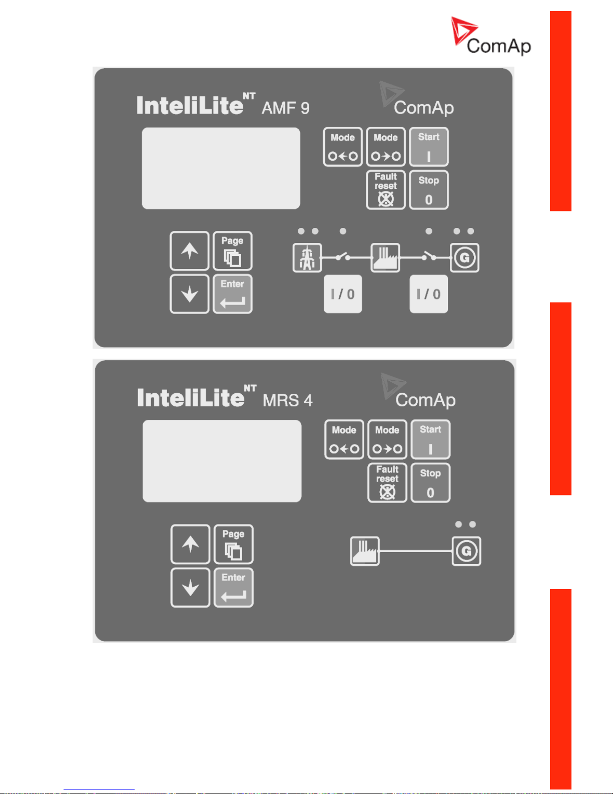
User Interface ........................................................................................................................................ 15
IL-NT Terminals..................................................................................................................................... 16
IL-NT Terminals................................................................................................................................. 16
Recommended Wiring ........................................................................................................................... 18
AMF – Wiring Diagram...................................................................................................................... 18
MRS – Wiring Diagram ..................................................................................................................... 19
Stand-by Applications............................................................................................................................ 20
Contactors (set point MCB Logic = “CLOSE-OFF”).......................................................................... 20
ATS with three stable positions (set point MCB Logic = “CLOSE-OFF”).......................................... 21
Getting Started ...................................................................................................................................... 22
How to install..................................................................................................................................... 22
Current measurement ....................................................................................................................... 24
Voltage measurement ....................................................................................................................... 25
Single phase applications ................................................................................................................. 25
Analog inputs..................................................................................................................................... 26
Inputs and Outputs ................................................................................................................................ 30
Binary Inputs – List............................................................................................................................ 30
Binary Outputs - List.......................................................................................................................... 31
Analog Inputs .................................................................................................................................... 33
Analog Outputs ................................................................................................................................. 33
Setpoints................................................................................................................................................ 34
Password........................................................................................................................................... 34
Basic Settings.................................................................................................................................... 34
^AMF Settings ................................................................................................................................... 36
*ECU-controlled engine support............................................................................................................ 38
Values read from ECU ...................................................................................................................... 39
Diagnostic messages read from ECU...............................................................................................39
Analog inputs..................................................................................................................................... 40
Connection description...................................................................................................................... 40
Sensor Specification.............................................................................................................................. 43
Alarm Management ............................................................................................................................... 44
Sensor Fail (FLS) ............................................................................................................................. 44
Warning (WRN)................................................................................................................................. 44
Shut down (SD)................................................................................................................................. 44
^Mains failure (MF)............................................................................................................................ 44
Gen-set Operation States...................................................................................................................... 47
List of possible events....................................................................................................................... 47
User Interface ........................................................................................................................................ 49
Page 3

InteliLiteNT– MRS3,4, AMF8,9, SW version 1.4, ©ComAp – October 2008 3
IL-NT-MRS3,4-AMF8,9-1.4-Reference Guide.pdf
Remote Control and Data Logging........................................................................................................ 50
Direct connection to the PC .............................................................................................................. 50
PC software – LiteEdit....................................................................................................................... 50
IL-NT-RD Remote display software....................................................................................................... 54
General description ........................................................................................................................... 54
Warning ! ........................................................................................................................................... 54
IL-NT-RD Software installation.......................................................................................................... 54
IL-NT-RD Wiring................................................................................................................................ 55
Function description .......................................................................................................................... 58
SW compatibility................................................................................................................................ 58
Technical Data....................................................................................................................................... 59
Inputs/Outputs overview.................................................................................................................... 59
Generator protections ....................................................................................................................... 59
Power supply..................................................................................................................................... 59
Operating conditions ......................................................................................................................... 60
Dimensions and weight ..................................................................................................................... 60
Mains and generator ......................................................................................................................... 60
Binary inputs and outputs.................................................................................................................. 61
Analog inputs..................................................................................................................................... 61
D+ terminal........................................................................................................................................ 61
*CAN bus interface............................................................................................................................ 61
IL-NT RS232 interface (optional card) .............................................................................................. 62
IL-NT RS232-485 interface (optional card) .......................................................................................62
IL-NT S-USB interface (optional card) .............................................................................................. 62
IL-NT AOUT8 interface (optional card) ............................................................................................. 62
IG-IB .................................................................................................................................................. 63
Page 4

InteliLiteNT– MRS3,4, AMF8,9, SW version 1.4, ©ComAp – October 2008 4
IL-NT-MRS3,4-AMF8,9-1.4-Reference Guide.pdf
General Guidelines
What describes this manual?
IMPORTANT SAFETY INSTRUCTIONS
SAVE THESE INSTRUCTION - This manual contains important instructions for IGS-NT
controllers family that shall be followed during installation and maintenance of the Inteli NT genset
controllers.
It is intended for use by Gen-set control panel builders and for everybody who is concerned with
installation, operation and maintenance of the gen-set.
This manual describes „MRS3/4 and AMF8/9“ software which is designed for single set and stand-by
applications.
What is the purpose of the manual?
This manual provides general information how to install and operate InteliLite NT MRS3/4 or AMF8/9
controller.
This manual is dedicated for
Operators of gen-sets
Gen-set control panel builders
For everybody who is concerned with installation, operation and maintenance of the gen-set
!! Warnings !!
Remote control
InteliLite controller can be remotely controlled. In case of the work on the gen-set check, that nobody
can remotely start the engine.
To be sure:
Disconnect remote control via RS232 line
Disconnect input REM START/STOP
or
Disconnect output STARTER and outputs GCB CLOSE/OPEN and MCB CLOSE/OPEN
Because of large variety of InteliLiteNT parameters settings, it is not possible to describe any
combination. Some of InteliLite functions are subject of changes depend on SW version.
The data in this manual only describes the product and are not warranty of performance or
characteristic.
InteliLite controller SW and HW versions compatibility
Be aware that IL-NT SW version 1.2.1 and older is not possible to use with IL-NT HW version 1.3 and
newer!!! Software IL-NT 1.3 is compatible with IL-NT hardware version 1.3 and older.
Symbols
Symbols used in this manual:
Grounding
point symbol
AC voltage
symbol
DC voltage
symbol
Page 5

InteliLiteNT– MRS3,4, AMF8,9, SW version 1.4, ©ComAp – October 2008 5
IL-NT-MRS3,4-AMF8,9-1.4-Reference Guide.pdf
Text
PAGE (Capital letters in the frame) buttons on the front panel
Break Return (Italic) set points
Generator protections (Bold) Set point group
REMOTE START/STOP (Capital letters) binary inputs and outputs
*Something (Symbol * before text) valid only for IL-NT MRS4 and AMF9
^Something (Symbol ^ before text) valid only for IL-NT AMF8 and AMF9
(icon) Setpoint is password protected
Note:
ComAp believes that all information provided herein is correct and reliable and reserves the right to
update at any time. ComAp does not assume any responsibility for its use unless otherwise expressly
undertaken.
Note:
SW and HW must be compatible (e.g. IL-NT-AMF9 firmware and IL-NT AMF9 HW) otherwise the
function will be disabled. If wrong software is downloaded, message HARDWARE INCOMPATIBLE
appears on controller screen. In this case use Boot load (jumper) programming – close Boot jumper
and follow instructions in LiteEdit, download correct software.
WARNING – VERY IMPORTANT !!!
Every time you want to disconnect following InteliLiteNT controller terminals:
• Mains voltage measuring and / or
• Binary output for MCB control
Switch InteliLite to MAN or disconnect the Binary outputs Starter and Fuel to avoid
unexpected automatic start of genset and GCB closing.
Hint: Applications works without MCB and GCB feedback.
!!! CAUTION !!!
Dangerous voltage
In no case touch the terminals for voltage and current measurement!
Always connect grounding terminals!
In any case do not disconnect InteliLite
NT
CT terminals !
Adjust set points
All parameters are preadjusted to their typical values. But the set points in the “Basic settings” settings
group !!must!! be adjusted before the first startup of the gen-set.
!!! WRONG ADJUSTMENT OF BASIC PARAMETERS
CAN DESTROY THE GEN-SET !!!
The following instructions are for qualified personnel only. To avoid personal injury do not
perform any action not specified in this User guide !!!
Page 6

InteliLiteNT– MRS3,4, AMF8,9, SW version 1.4, ©ComAp – October 2008 6
IL-NT-MRS3,4-AMF8,9-1.4-Reference Guide.pdf
General Description
Description of the controller system (with all options)
InteliLite
NT
MRS3/4, AMF8/9 is a comprehensive AMF-controller for single generating sets and sets
operating in stand-by mode. IL-NT AMF9 features extended support of electronic engines.
InteliLite
NT
controllers are equipped with a powerful graphic display showing icons, symbols and bargraphs for intuitive operation, which sets, together with high functionality, new standards in Gen-set
controls.
InteliLite
NT
automatically starts the Gen-set, closes the Gen-set C.B. when all conditions are met, then
stops the engine on external signal or by pressing push buttons.
Gen-set C.B. is controlled by binary output but works without feedback signal. Mains C.B. works
similary.
InteliLite
NT
provides gas engine support without ventilation.
The key feature of InteliLite
NT
is its easy-to-use operation and installation. Predefined configurations
for typical applications are available as well as user-defined configurations for special applications.
Software and Hardware Compatibility
It is possible to use HW from higher type of controller for SW of lower type of controller. The table
below describes software and hardware compatibility.
Software Compatible Hardware
IL-NT MRS3 IL-NT MRS10
IL-NT MRS4 IL-NT MRS15
IL-NT AMF8 IL-NT AMF20
all IL-NT AMF/MRS IL-NT AMF25
What is in the package?
Accessories Description Optional / Obligatory
IL-NT AMF/MRS InteliLiteNT central unit Obligatory
IL-NT-RS232 RS232 communication card Optional
IL-NT-RS232-485 RS232 and RS485 communication card Optional
IL-NT-S-USB S-USB service USB card Optional
IL-NT AOUT8 Gauge driver card Optional
**IL-NT RD Remote display software Optional
AT -LINK-CONV Service programming RS232 interface Optional
**Remote display for IL-NT controllers uses standard IL-NT controller with Remote
display software.
Extension modules
IGL-RA15 - Remote annunciator and IG-IOM/PTM - I/O extension module are
not supported in IL-NT MRS3/4 and IL-NT AMF8/9.
Hint:
For detailed information about extension modules used with IL-NT controllers, please see the IL-NTAccessory Modules manual.
Page 7
InteliLiteNT– MRS3,4, AMF8,9, SW version 1.4, ©ComAp – October 2008 7
IL-NT-MRS3,4-AMF8,9-1.4-Reference Guide.pdf
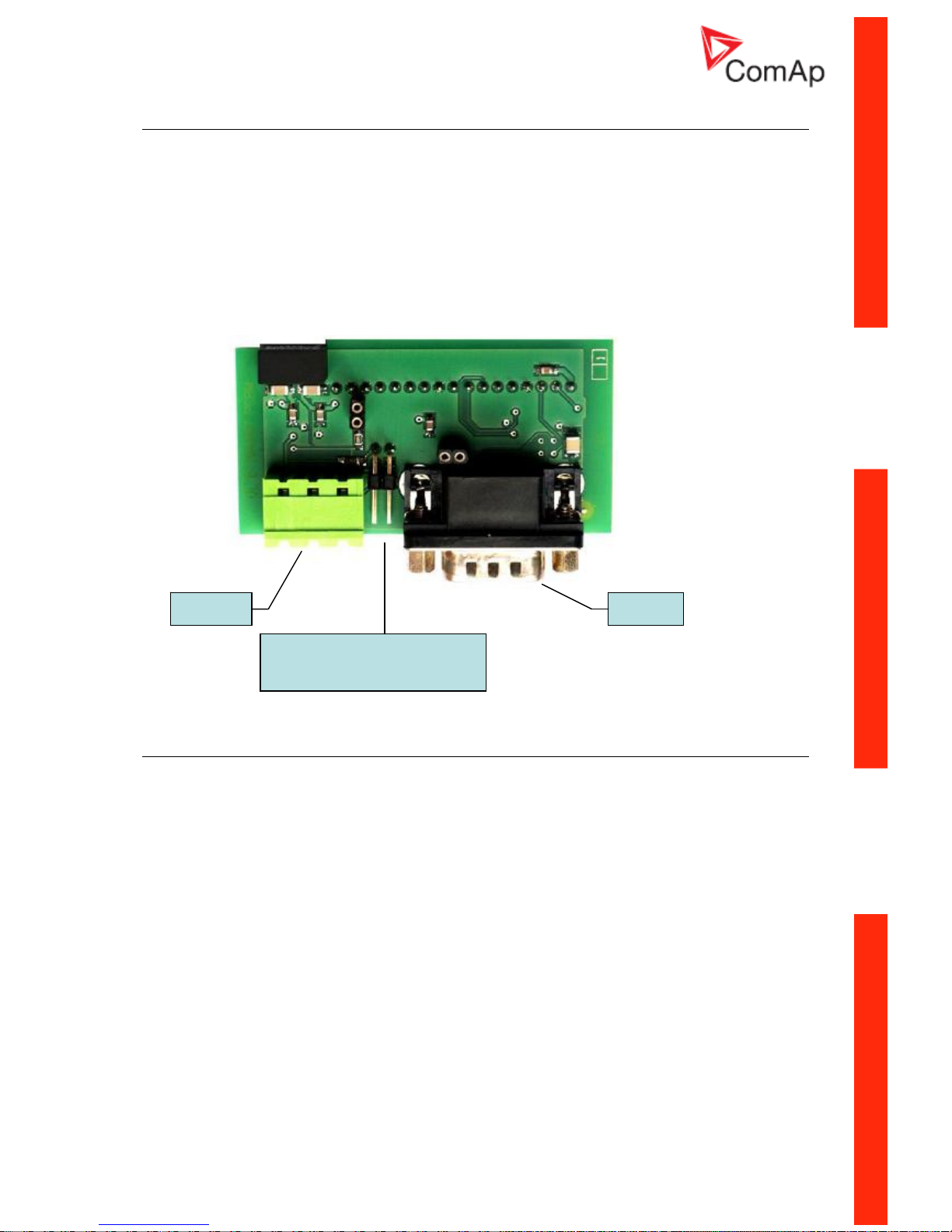
IL-NT RS232 Communication module
IL-NT RS232 is optional plug-in card to enable InteliLite
NT
for RS232 communication. This is required
for computer or Modbus connection. Card inserts into expansion slot back on the controller.
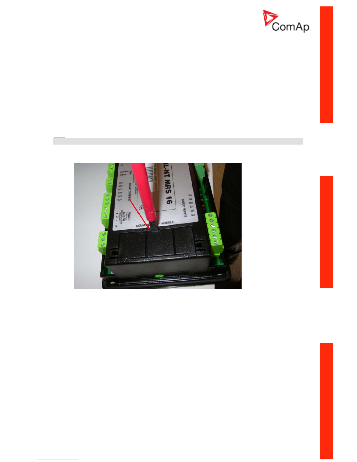
To insert the module, you must open the cover first (use screwdriver to open) and then insert the
module into slot. Once you have insert it, the module will snap under plastic teeth. It is supposed to be
installed permanently. Should you need to remove it, the safest way is to remove whole back cover
and than remove module manually.
How to install RS 232 communication module:
Hint:
The following procedure is analogic also for other communication modules.
1. Insert a screwdriver into the slot of the cover.
2. Move the screwdriver to set apart the small cover. Be careful!
Page 8
InteliLiteNT– MRS3,4, AMF8,9, SW version 1.4, ©ComAp – October 2008 8
IL-NT-MRS3,4-AMF8,9-1.4-Reference Guide.pdf
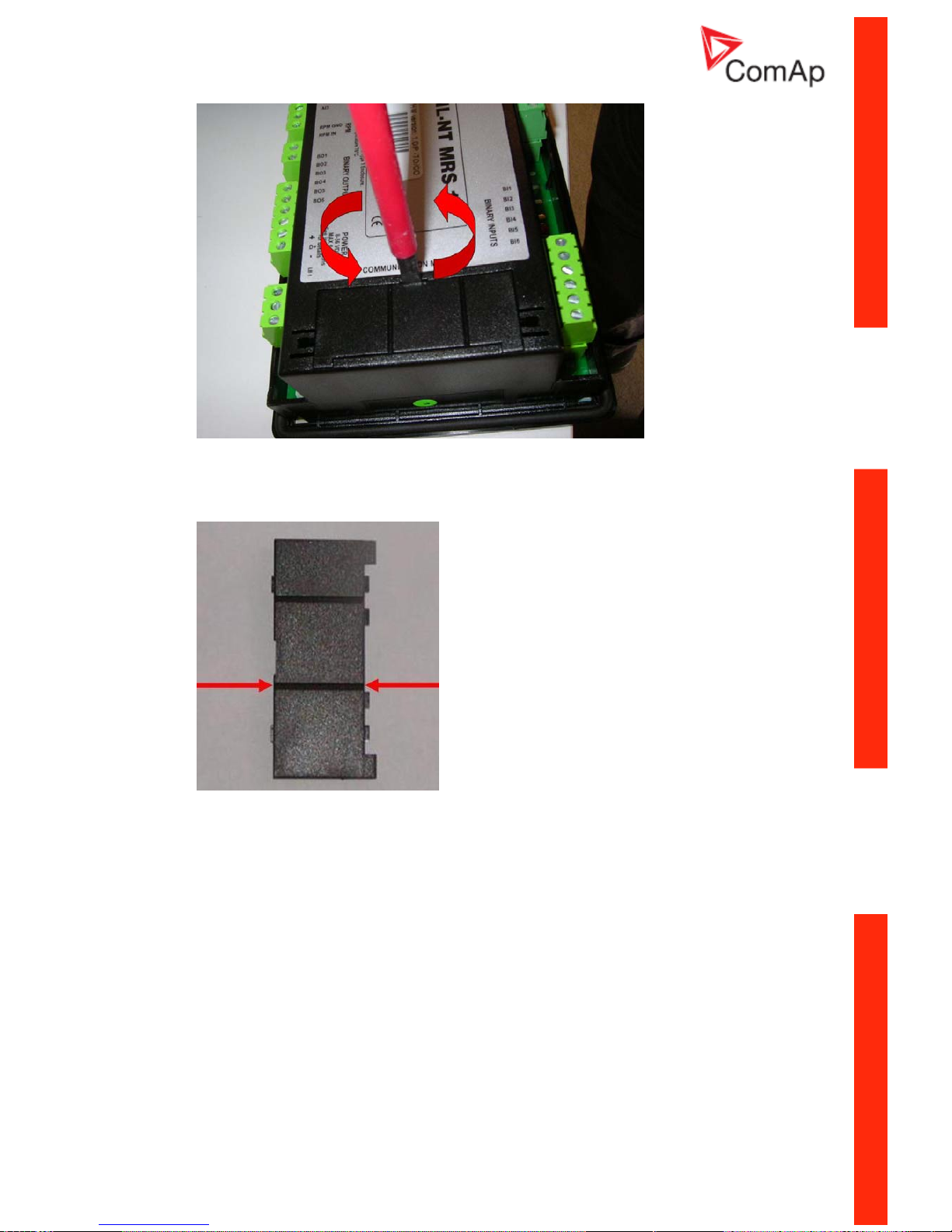
3. Remove the small cover.
4. Break apart the small cover into two pieces. Do not throw away the smaller part!
Page 9
InteliLiteNT– MRS3,4, AMF8,9, SW version 1.4, ©ComAp – October 2008 9
IL-NT-MRS3,4-AMF8,9-1.4-Reference Guide.pdf
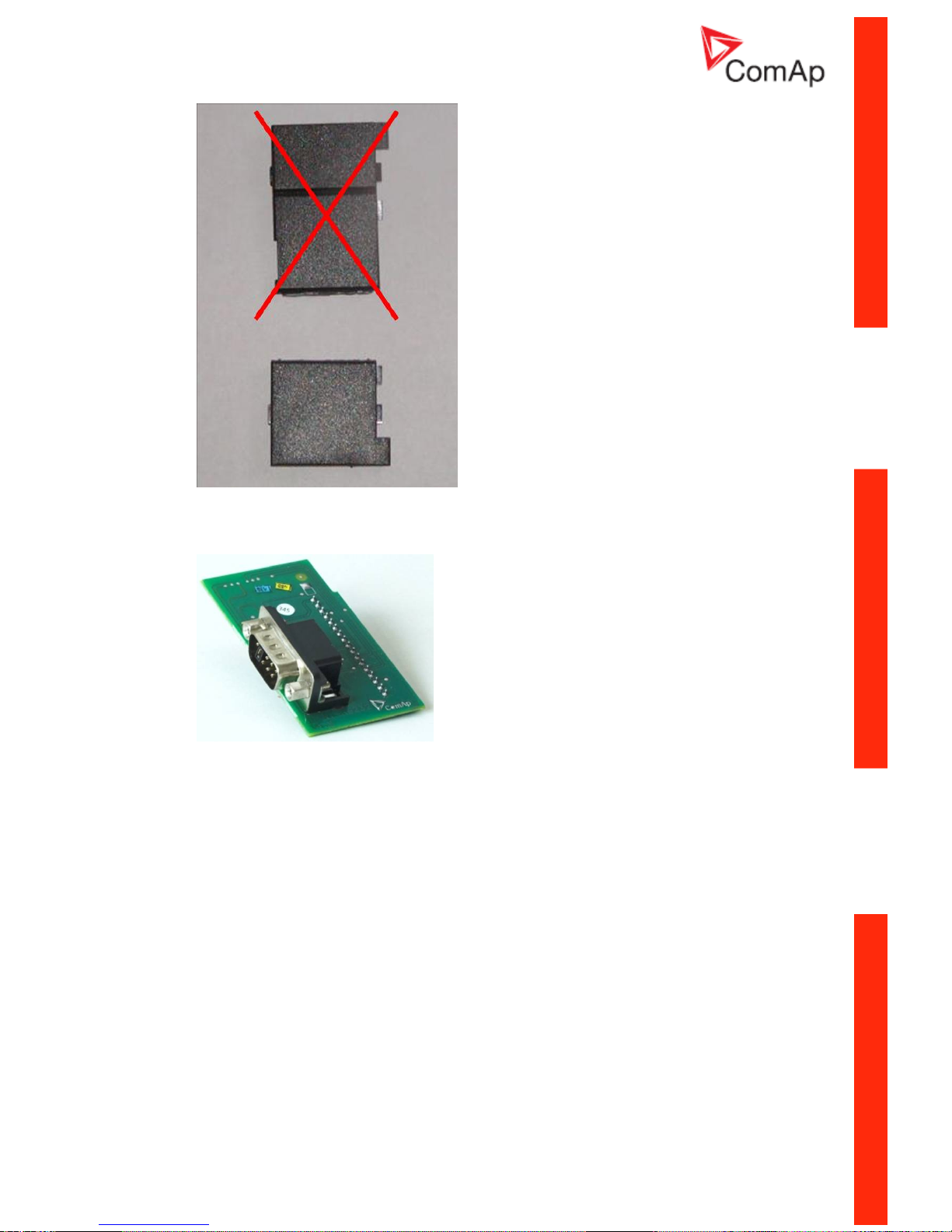
5. Take RS 232 communication module.
Page 10
InteliLiteNT– MRS3,4, AMF8,9, SW version 1.4, ©ComAp – October 2008 10
IL-NT-MRS3,4-AMF8,9-1.4-Reference Guide.pdf
6. Plug RS 232 communication module into the slot of the controller.
7. Put back the small cover.
Hint:
When you insert RS 232 communication module, the boot jumper is hidden. For that reason we
recommend to use RS 232 communication module with the boot jumper placed on it. See pictures
below:
RS 232 communication module with the boot jumper.
Page 11
InteliLiteNT– MRS3,4, AMF8,9, SW version 1.4, ©ComAp – October 2008 11
IL-NT-MRS3,4-AMF8,9-1.4-Reference Guide.pdf
IL-NT RS232-485 Communication module
IL-NT RS232-485 is optional plug-in card to enable InteliLite
NT
the RS232 and RS485 communication.
This is required for computer or Modbus connection. Card inserts into expansion slot back on the
controller. The IL-NT RS232-485 is a dual port module with RS232 and RS485 interfaces at
independent COM channels. The RS232 is connected to COM1 and RS485 to COM2.
To insert the module, please follow the instructions for IL-NT RS232 module, procedure is analogous.
You must open the cover first (use screwdriver to open) and then insert the module into slot. Once you
have insert it, the module will snap under plastic teeth. It is supposed to be installed permanently.
Should you need to remove it, the safest way is to remove whole back cover and than remove module
manually.
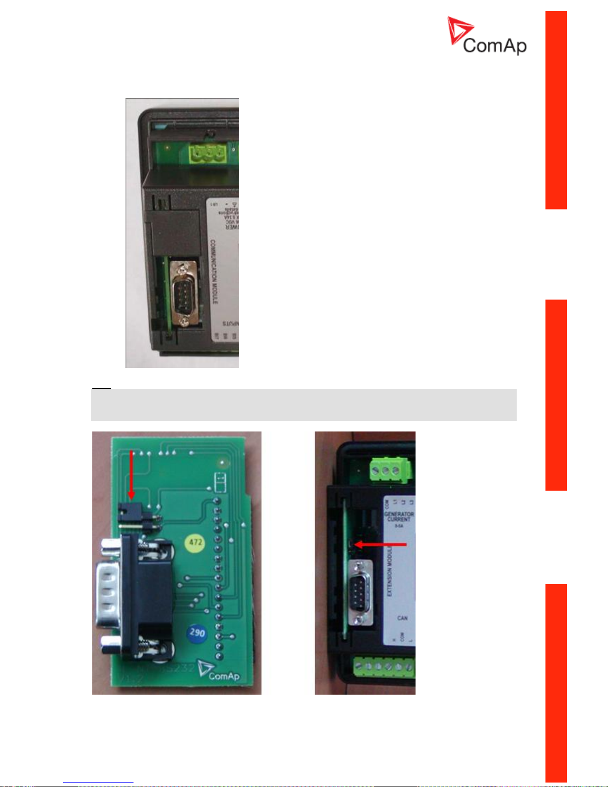
RS485 RS232
Boot jumper
RS485 Terminator jumper
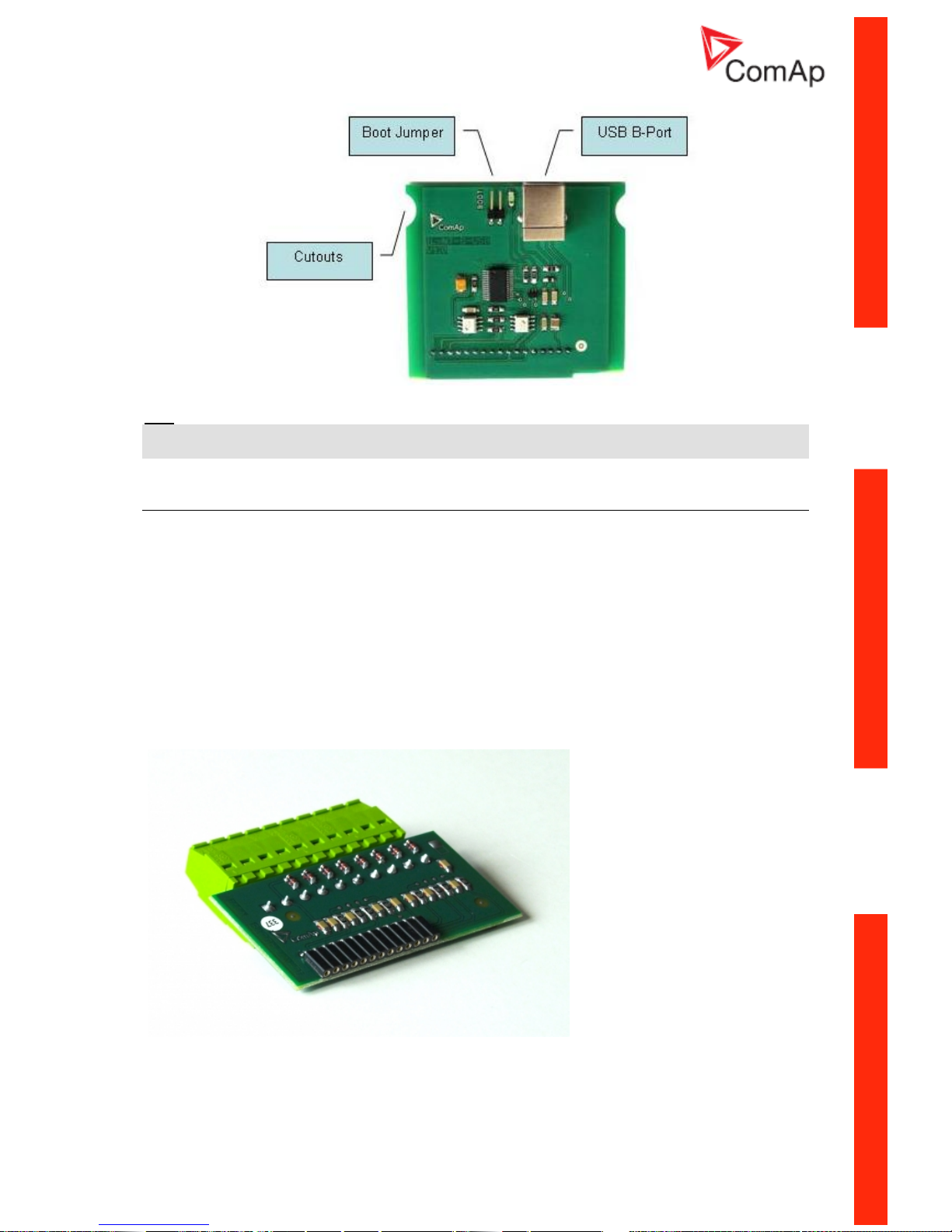
IL-NT S-USB Service USB communication module
IL-NT S-USB is optional plug-in card to enable InteliLite
NT
communication via USB port. This is
required for computer or Modbus connecting. Card inserts into expansion slot back on the controller.
To insert the module, please follow the instructions for IL-NT RS232 module, procedure is analogous.
You must open the cover first (use screwdriver to open) and then insert the module into slot. Once you
have inserted it, part of the module will remain over plastic box. It is supposed to be used as a service
tool. When you need to remove it, grab module in cutouts and pull it up manually.
Page 12
InteliLiteNT– MRS3,4, AMF8,9, SW version 1.4, ©ComAp – October 2008 12
IL-NT-MRS3,4-AMF8,9-1.4-Reference Guide.pdf
Hint:
Use the shielded USB A-B cable with this module! Recommended is ComAp cable – Order code:
“USB-LINK CABLE 1.8M”.
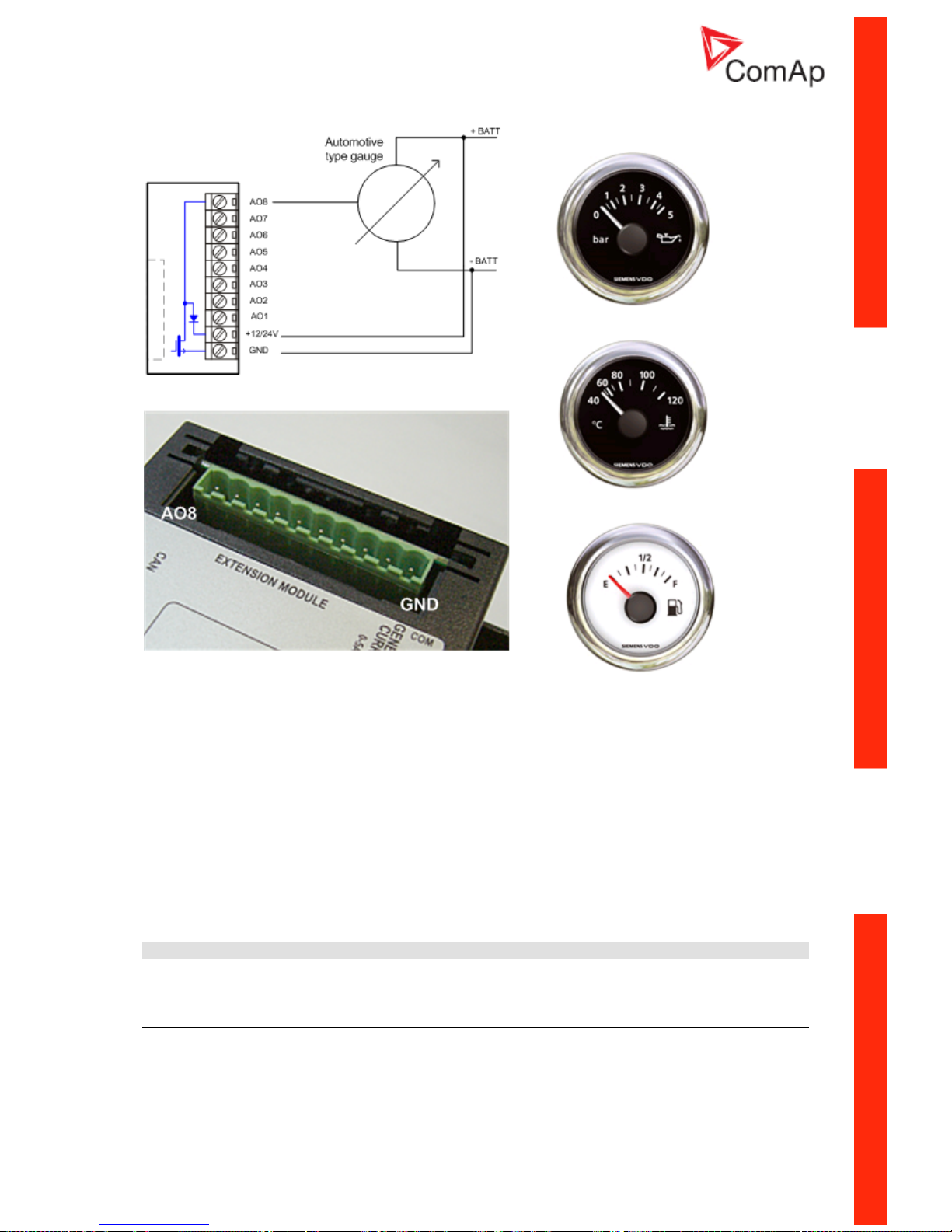
IL-NT AOUT8 Gauge driver module
IL-NT AOUT8 is optional plug-in card. Through this card controller can drive up to 8 VDO style
industrial/automotive gauges. Noncompensated gauges like 0-10V or 0-20mA are not supported.
Gauge type and value are configured in LiteEdit software. Any analog value from controller may be
shown in that way.
To insert the module, you must open the cover first (use screwdriver to open) and then insert the
module into slot. Once you have insert it, the module will snap under plastic teeth. It is supposed to be
installed permanently. Should you need to remove it, the safest way is to remove whole back cover
and than remove module manually.
Installing IL-NT AOUT8 module is similar to installing RS 232 module. The difference is that module
fits to “extension module” slot and after installing IL-NT AOUT8 you do not put back the small cover.
IL-NT AOUT8 module:
:
Page 13
InteliLiteNT– MRS3,4, AMF8,9, SW version 1.4, ©ComAp – October 2008 13
IL-NT-MRS3,4-AMF8,9-1.4-Reference Guide.pdf
Typical wiring
IL-NT RD Remote display software
IL-NT RD is remote display software for a controller. Remote display provides the same control and
monitoring functions as controller itself. Remote display for IL-NT controllers uses standard IL-NT
controller with Remote display software. No further programing of the display is required – unit is self
configurable from the main controller. It is connected with the controller via IL-NT-RS232
communication modules using RS232 line. Longer distances (up to 1200m) are possible using IL-NTRS232-485 communication module or when RS232/RS485 converters are used.
The IL-NT RD hardware type should fit to the master IL-NT.
Hint:
Please see the “IL-NT-RD Remote display software” chapter for more details.
IG-IB Internet bridge
IG-IB Internet bridge enables InteliLite
NT
for Ethernet/Internet communicatons. It is connected to
controller via RS232 line.
See the InteliCommunication guide for further details.
Page 14

InteliLiteNT– MRS3,4, AMF8,9, SW version 1.4, ©ComAp – October 2008 14
IL-NT-MRS3,4-AMF8,9-1.4-Reference Guide.pdf
Programming of IL-NT controller
Programming is possible only in MAN mode when the engine is not running.
Hint:
For more information on programing, see LiteEdit Reference Guide.
Page 15

InteliLiteNT– MRS3,4, AMF8,9, SW version 1.4, ©ComAp – October 2008 15
IL-NT-MRS3,4-AMF8,9-1.4-Reference Guide.pdf
User Interface
Since IL-NT 1.3 SW there is an interchangable User Interface on controller. It allows two different
modes of displaying controller menu.
The first mode called USER is dedicated for users who prefer easy function and need only monitor
actual values of engine and generator, see alarms or change language settings.
Second mode is called ENGINEER and it is dedicated for advaced users, who desire to change the
settings of controller and monitor all values
.
Changing the mode of User Interface is possible from default measuring screen of controller by
simultaneous pressing the ENTER and PAGE button and than press again PAGE. On screen will be
displeyed the choice of two different User Interfaces.
Please see latest IL-NT Operator Guide for detailed description.
Page 16
InteliLiteNT– MRS3,4, AMF8,9, SW version 1.4, ©ComAp – October 2008 16
IL-NT-MRS3,4-AMF8,9-1.4-Reference Guide.pdf
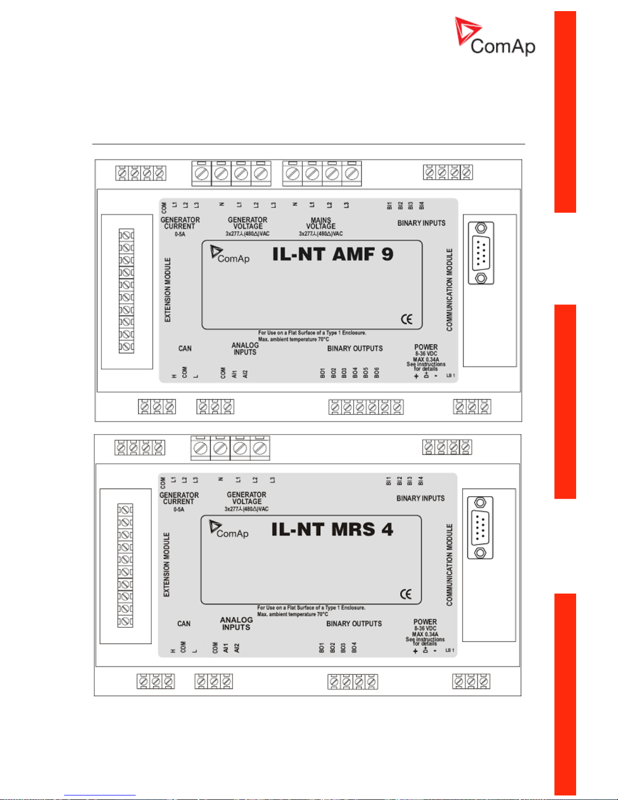
IL-NT Terminals
IL-NT Terminals
Page 17
InteliLiteNT– MRS3,4, AMF8,9, SW version 1.4, ©ComAp – October 2008 17
IL-NT-MRS3,4-AMF8,9-1.4-Reference Guide.pdf
Page 18
InteliLiteNT– MRS3,4, AMF8,9, SW version 1.4, ©ComAp – October 2008 18
IL-NT-MRS3,4-AMF8,9-1.4-Reference Guide.pdf
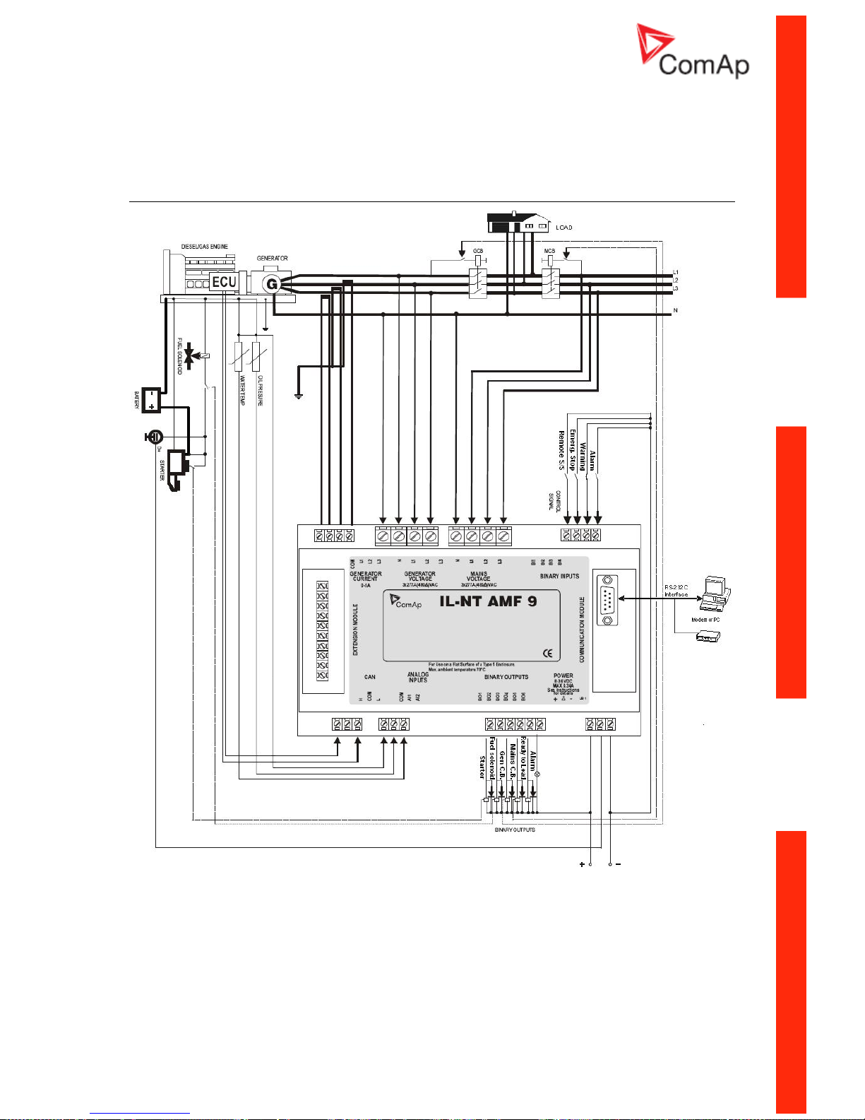
Recommended Wiring
AMF – Wiring Diagram
Page 19
InteliLiteNT– MRS3,4, AMF8,9, SW version 1.4, ©ComAp – October 2008 19
IL-NT-MRS3,4-AMF8,9-1.4-Reference Guide.pdf
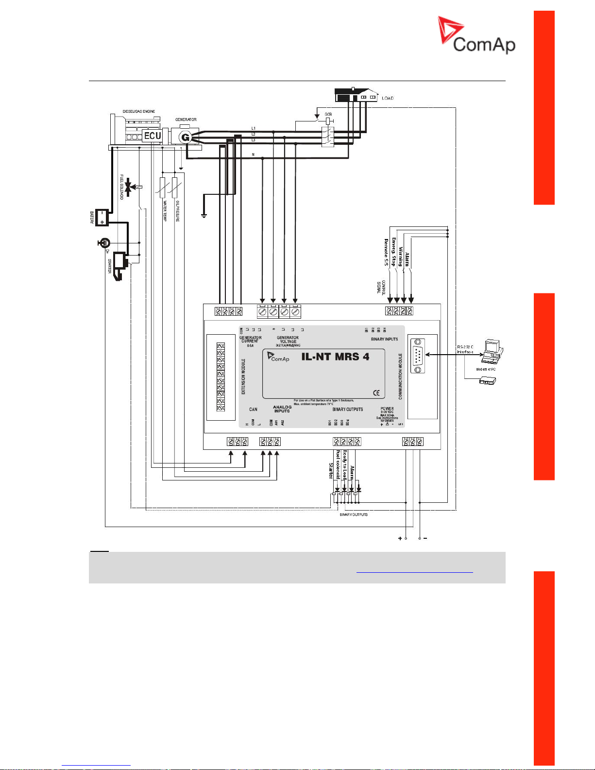
MRS – Wiring Diagram
Hint:
MCB and GCB is recommended to be mechanically interlocked.
It is possible to start Volvo and Scania engines via CAN bus. See Engines started via CAN bus.
If D+ function is not used connect the D+ terminal to battery positive.
Page 20

InteliLiteNT– MRS3,4, AMF8,9, SW version 1.4, ©ComAp – October 2008 20
IL-NT-MRS3,4-AMF8,9-1.4-Reference Guide.pdf
St and-by Applications
Contactors (set point MCB Logic = “CLOSE-OFF”)
Page 21

InteliLiteNT– MRS3,4, AMF8,9, SW version 1.4, ©ComAp – October 2008 21
IL-NT-MRS3,4-AMF8,9-1.4-Reference Guide.pdf
ATS with three stable positions
(set point MCB Logic = “CLOSE-OFF”)
Page 22

InteliLiteNT– MRS3,4, AMF8,9, SW version 1.4, ©ComAp – October 2008 22
IL-NT-MRS3,4-AMF8,9-1.4-Reference Guide.pdf
Getting Started
How to install
General
To ensure proper function:
Use grounding terminals.
Wiring for binary inputs and analog inputs must not be run with power cables.
Analog and binary inputs should use shielded cables, especially when length >3m.
Wiring
Tightening torque, allowable wire size and type, for the Field-Wiring Terminals:
For Mains(Bus) Voltage and Generator Voltage terminals
Specified tightening torque is 0,56Nm (5,0 In-lb)
Use only diameter 2,0-0,5mm (12-24AWG) conductor, rated for 90°C minimum.
For other controller field wiring terminals
Specified tightening torque 0,79Nm (7,0 In-lb)
Use only diameter 2,0-0,5mm (12-26AWG) conductor, rated for 75°C minimum.
Use copper conductors only.
Grounding
To ensure proper function:
The shortest possible piece of wire should be used for controller grounding.
Use cable min. 2,5mm
2
Brass M4x10 screw with star washer securing ring type grounding terminal shall be used.
The negative battery terminal has to be properly grounded.
Power supply
To ensure proper function:
Use min. power supply cable of 1.5mm
2
Maximum continuous DC power supply voltage is 36VDC. Maximum allowable power supply voltage
is 39VDC. The InteliLite’s power supply terminals are protected against large pulse power
disturbances. When there is a potential risk of the controller being subjected to conditions outside its
capabilities, an outside protection devise should be used.
Hint:
The InteliLite controller should be grounded properly in order to protect against lighting strikes!!
The maximum allowable current through the controller’s negative terminal is 4A (this is dependent on
binary output load).
For the connections with 12VDC power supply, the InteliLite
NT
includes internal capacitors that allow
the controller to continue operation during cranking if the battery voltage dip occurs. If the voltage
before dip is 10V, after 100ms the voltage recovers to 7 V, the controller continues operating. During
this voltage dip the controller screen backlight can turn off and on but the controller keeps operating.
It is possible to further support the controller by connecting the external capacitor and separating
diode or I-LBA module:
Page 23

InteliLiteNT– MRS3,4, AMF8,9, SW version 1.4, ©ComAp – October 2008 23
IL-NT-MRS3,4-AMF8,9-1.4-Reference Guide.pdf
The capacitor size depends on required time. It shall be approximately thousands of microFarads.
The capacitor size should be 5 000 microFarad to withstand 150ms voltage dip under following
conditions:
Voltage before dip is 12V, after 150ms the voltage recovers to min. allowed voltage, i.e. 8V
Or by connecting special I-LBA Low Battery Adaptor module:
The I-LBA module ensures min. 350ms voltage dip under following conditions:
RS232 and other plug-in module is connected.
Voltage before dip is 12V and after 350ms the voltage recovers to min. allowed voltage 5V.
The I-LBA enables controller operation from 5VDC (for 10 to 30 sec).
The wiring resistance from battery should be up to 0.1 Ohm for I-LBA proper function.
Note:
I-LBA may not eliminate voltage drop when used with low temperature (-40°C) version of controller
and display heating element is on (below 5°C). Current drain of heating element exhausts LBA
capacitors very fast .
Power supply fusing
A one-amp fuse should be connected in-line with the battery positive terminal to the controller and
modules. These items should never be connected directly to the starting battery.
Fuse value and type depends on number of connected devices and wire length.
Recommended fuse (not fast) type - T1A. Not fast due to internal capacitors charging during power
up.
Page 24

InteliLiteNT– MRS3,4, AMF8,9, SW version 1.4, ©ComAp – October 2008 24
IL-NT-MRS3,4-AMF8,9-1.4-Reference Guide.pdf
Binary output protections
Do not connect binary outputs directly to DC relays without protection diodes, even if they are not
connected directly to controller outputs.
RPM reading
RPM are readed from frequency of generator voltage. The frequency and consequently the RPM are
readed when generator voltage is higher than 10V and RPM are readed only if frequency si higher
than 1Hz.
Current measurement
To ensure proper function
Use cables of 2,5mm
2
Use transformers to 5A
Connect CT according to following drawings
Page 25

InteliLiteNT– MRS3,4, AMF8,9, SW version 1.4, ©ComAp – October 2008 25
IL-NT-MRS3,4-AMF8,9-1.4-Reference Guide.pdf
Voltage measurement
G
GENERATOR MAINS
L3L2L1N
L1
L2
L3
N
L3L2L1N
G
GENERATOR MAINS
L3L2L1N
L1
L2
L3
L3L2L1N
Hint:
No separation transformers for three wires voltage connection (without N) are needed.
Switchboard lighting strikes protection according standard regulation is expected !!!
Single phase applications
There is not a separate archive file for single-phase applications. Use standard ail archives.
Recommended wirings
Generator (and mains) single-phase voltage has to be connected to all three-voltage terminals L1, L2
and L3. Generator current has to be connected to L1l and COM terminals only.
Voltage measurement
G
GENERATOR MAINS
L3L2L1N
L
N
L3L2L1N
Hint:
Switchboard lighting strikes protection according standard regulation is expected !!!
Current measurement
To ensure proper function
Use cables of 2,5mm
2
Use transformers to 5A
Connect CT according to following drawings. Terminals L2l and L3l are opened.
Page 26

InteliLiteNT– MRS3,4, AMF8,9, SW version 1.4, ©ComAp – October 2008 26
IL-NT-MRS3,4-AMF8,9-1.4-Reference Guide.pdf
Analog inputs
Two analog inputs are available on the IL-NT.
Configuration
Each analog input can be configured by LiteEdit software following way.
Analog input item LiteEdit Possibility
Type Type Not used
Alarm
Analog input isn’t used
Analog input name Name Up to 14 ASCII characters
Config of input Config Analog
Binary (not supp. by PTM)
Tri-state (not supp. by PTM)
ECU
Analog measuring in specified
range.
Binary: open/close - threshold
750 Ω.
Three-state: open/close threshold 750 Ω,
Failure <10 Ω or > 2400 Ω
Value is read from ECU
Physical dimension Dim bar,%,°C, … Up to 4 ASCII characters
(Valid only for analog inputs)
Polarity Contact type NC
NO
Valid only for binary and threestate inputs
Valid only for binary and threestate inputs
Over Overstep. Sensor Fail does
not activate protection.
Over+Fls Overstep and Sensor Fail
activates protection.
Under Under step. Sensor Fail does
not activate protection.
Protection direction Protection
Under+Fls Under step and Sensor Fail
activates protection.
Sensor characteristic Sensor Predefined user curves User changeable and
configurable
Resolution Resolution 0 – 0,00001 Sensor resolution
(Valid only for analog inputs)
User Curves are adjustable in LiteEdit.
Each Analog input has separate set points for two level alarm setting. Analog input alarm levels and
delay adjust in Basic settings group.
Page 27

InteliLiteNT– MRS3,4, AMF8,9, SW version 1.4, ©ComAp – October 2008 27
IL-NT-MRS3,4-AMF8,9-1.4-Reference Guide.pdf
Connection of IL-NT analog inputs
AI1AI2
2 x RESISTIVE
SENSOR
COM
-POWER
Standard connection of three resistive sensors
to analog inputs.
Analog inputs are designed for resistive sensors with resistance in range of 0Ω to 2,4kΩ.
To ensure a proper function use shielded cables, especially for length over >3m.
Configure input as binary/tristate
- Analog inputs configured as binary or tristate have fixed shutdown alarm.
- Select type of the contact. NO = NormallyOpen, active when closed. NC = NormallyClosed,
active when opened.
- Threshold level in case an analog input is configured as binary or tristate is 750 Ohm.
- In case an analog input is configured as tristate, values <10 Ohm and >2400Ohm are
evaluated as sensor failure (short or open circuit).
Unused analog inputs
Configure Type = Not used
Example of analog input configuration
Configure Engine Temp input for measuring in °C, VDO 40-120°C sensor, range -16 to 120 °C. Alarm
protection level set to 90 °C, shut down level 110 °C.
Start LiteEdit and select – Controller - Configuration – Modify – Engine Temp.
Set configuration for Engine temp analog input:
Type: Selection between Not used and Alarm
“Not used” – analog input isn’t used
”Alarm” – analog input is used
Set to: Alarm
Name: Name of the analog input. Maximally 14 letters.
Set to: Engine Temp
Config: Selection between Analog, Binary Tri-state input.
“Analog” – resistor sensor is connected to Analog input.
“Binary” – open/close contact is connected between Analog input and COM terminal of Analog inputs.
Analog input detects only open/close state.
“Tri-state” – open/close contact is connected parallel to one of two serial resistors between Analog
input and COM terminal of Analog inputs.
Set to: Analog
Alarm Properties: Selection between different direction of protection – Under Limit, Over Limit or
combination with Fail sensor.
“Engine running only” – check this setting if you wish to active protection on analog input only while
engine is running, not, when it stops.
Page 28

InteliLiteNT– MRS3,4, AMF8,9, SW version 1.4, ©ComAp – October 2008 28
IL-NT-MRS3,4-AMF8,9-1.4-Reference Guide.pdf
Set to: Over Limit
Contact type: selection of polarity only when analog input is configured as Binary or Tri-state. When
is analog input configured as analog this setting has no sense.
„NC“ – polarity of binary or tri-state input
„NO“ – polarity of binary or tri-state input
Sensor: selection of sensor characteristic
„Unused input“ - when Analog input is not used. On the InteliLite screen is displayed „####“ value, no
alarm is detected.
Default user curves predefined on AI1 – AI3:
„VDO 10 Bar“ – VDO pressure sensor
„VDO 40-120 °C“ – VDO temperature sensor
„VDO level %“ – VDO level sensor
Set to: VDO 40-120 °C
When you choose the predefined or user curve the Sensor Name, Dim and Resolution are setted
automaticly according to curve, user modification is possible.
Sensor Name: Name of used sensor, up to 14 letters can be used.
Dim: Name of measured unit (Bar, °C, %, …), up to 4 letters can be used.
Resolution: setting of resolution of measured value.
„0“ - e.g. 360 kPa, 100%, 50 °C
„1“ – e.g. 360.0 kPa
„2“- e.g. 360.00 kPa
„3“ - e.g. 360.000 kPa
Set to: 1
When Analog input configuration is finished set the setpoints AI1 Wrn, AI1 Sd, AI1 Del in Basic
setting group.
Number of decimal points of AIx Wrn and AIx Sd is the same as the configured number of decimal
points of measured value.
Binary inputs
+
Battery
-
iL
4k7
Ω
+
-
Power
Supply
Page 29

InteliLiteNT– MRS3,4, AMF8,9, SW version 1.4, ©ComAp – October 2008 29
IL-NT-MRS3,4-AMF8,9-1.4-Reference Guide.pdf
Binary outputs
+
Battery
-
iL
LOAD
+
-
Power
Supply
Page 30

InteliLiteNT– MRS3,4, AMF8,9, SW version 1.4, ©ComAp – October 2008 30
IL-NT-MRS3,4-AMF8,9-1.4-Reference Guide.pdf
Inputs and Outputs
For Inputs/Outputs overview table see chapter Technical Data.
Not used
Binary input has no function. Use this configuration when binary input is not connected.
Alarm
If the input is closed (or opened) selected alarm is activated.
Binary Alarm configuration items
Name 14 characters ASCII string
NC Normally closed Contact type
NO Normally opened
Warning Alarm type
Shut down
All the time Valid if checkbox “Engine running
only” is not checked
Alarm active
Engine running only Valid if checkbox “Engine running
only” is checked
Control
Use this setting to configure the desired function from the list below.
Hint:
In 1.2 version of FW, there is a possibility to function without feedback from GCB and MCB.
Binary Inputs – List
Rem Start/Stop
External request for engine run. AUT mode only.
Page 31

InteliLiteNT– MRS3,4, AMF8,9, SW version 1.4, ©ComAp – October 2008 31
IL-NT-MRS3,4-AMF8,9-1.4-Reference Guide.pdf
Emergency Stop
If the input is opened, shut down is immediately activated. Input is inverted (normally closed) in default
configuration.
Remote MAN
If the input is active, MAN Mode is forced to the controller independently on the position of the MODE
selector.
Remote AUT
If the input is active, AUTO Mode is forced to the controller independently on the position of the MODE
selector. If another of „remote“ inputs is active, then the REMOTE AUT input has the lowest priority.
^MainsFailBlock
If the input is closed, the automatic start of the gen-set at Mains failure is blocked. In case of running
gen-set the GCB is opened, gen-set goes to Cooling procedure and stops.
The input simulates healthy Mains.
Binary Outputs - List
Not used
Output has no function.
Starter
The closed relay energizes the starter motor.
The relay opens if:
• the “firing” speed is reached or
• maximum time of cranking is exceeded or
• request to stop comes up
Fuel Solenoid
Closed output opens the fuel solenoid and enables the engine start.
The output opens if:
• EMERGENCY STOP comes or
• Cooled gen-set is stopped or
• in pause between repeated starts
Stop Solenoid
The closed output energizes stop solenoid to stop the engine.
The output is active at least for stop time, if the stop lasts longer, it stays active until all symptoms say
the engine is stopped.
The engine is stopped if:
• RPM < 2 and
• Generator voltage < 10V and
• Oil pressure < Engine params: StartingPoil.
Hint:
The engine can be started anytime, if all symptoms say the engine is steady regardless of the fact the
Stop Solenoid can still be active (in that case it is deactivated before cranking).
Prestart
The output closes prior to the engine start (Prestart) and opens when Starting RPM speed is reached.
During Crank Attempts the output is closed too.
The output could be used for pre-glow, pre-heat or prelubrication.
Page 32

InteliLiteNT– MRS3,4, AMF8,9, SW version 1.4, ©ComAp – October 2008 32
IL-NT-MRS3,4-AMF8,9-1.4-Reference Guide.pdf
Alarm
The output closes if :
• any alarm comes up or
• the gen-set malfunctions
The output opens if
• FAULT RESET is pressed
The output closes again if a new fault comes up.
^GCB Close/Open
The output controls the generator circuit breaker.
Hint:
Supposed time to close (reaction time) of GCB is 0,1 sec.
^Ready to AMF
The output is active, if the controller is able to start the engine (the output Ready to run is active) or
engine is already running and simultaneously the controller is in AUTO Mode.
Ready
The output is closed if following conditions are fulfilled:
• Gen-set is not running and
• No Shut down is active
• Controller is not in OFF Mode
Ready To Load
The output is closed if gen-set is running and all electric values are in limits no alarm is active - it is
possible to close GCB or it is already closed. The output opens during cooling state.
AL Mains Fail
Output closes if the mains over/under voltage alarm, voltage asymmetry alarm or mains over/under
frequency alarm activates.
The output opens, if
• alarm is not active and
• FAULT RESET is pressed
Not in AUT
The output is closed, if MAN Mode is selected.
*ECU PowerRelay
The output closes at the beginning of prestart and opens if the engine shall be stopped. The
communication failure with ECU is not evaluated while the output is not active even if it is not
configured. It means that if communication with ECU fails during engine stop for example (ECU
PowerRelay output would be closed if configured) the controller doesn't issue any related alarms.
Battery Flat
Output closes when IL-NT performs reset during start procedure (probably due to weak battery) or
when battery under voltage warning appears.
The output opens, if
• alarm is not active and
• FAULT RESET is pressed
Glow Plugs
The output closes prior to the engine start (by Prestart Time) and opens at the beginning of cranking
time. In case of repeated crank attempts the output closes always prior to the other engine start
attempts (by Prestart Time) and is opened during crank attempts.
Page 33

InteliLiteNT– MRS3,4, AMF8,9, SW version 1.4, ©ComAp – October 2008 33
IL-NT-MRS3,4-AMF8,9-1.4-Reference Guide.pdf
Analog Inputs
It is possible to configure on each Analog input:
• Reading from IL Analog inputs or from Engine Control Unit via CAN bus (J1939)
• Sensor characteristics – from the list, or custom sensor curve
• Value dimension (e.g. psi - bars, °F - °C, % - l)
• Sensor resolution
Warning and shut-down limits are adjusted in Engine protect group.
The analog inputs are configurable. Use LiteEdit software to modify configuration. Default
configuration is:
Oil Pressure
Oil pressure analog input. Default range 0 to 10.0 bars.
Engine Temp
Water temperature analog input. Default range 40 to 120 °C.
Analog Outputs
Optional plug in card IL-NT AOUT8 provides eight Pulse-With-Modulation (PWM) outputs. These are
intended to drive VDO style analog gauges. This is to provide visual indication of typically ECU values
without installing aditional sensors on the engine. PWM signal emulates sensor which would be
typically mounted on the engine.
Any value from controler may be configured to the outputs. Use LiteEdit PC SW to configure
corresponding sensor/gauge curve and value selection.
Page 34

InteliLiteNT– MRS3,4, AMF8,9, SW version 1.4, ©ComAp – October 2008 34
IL-NT-MRS3,4-AMF8,9-1.4-Reference Guide.pdf
Setpoints
Password
EnterPassword
Password is a four-digit number. Password enables change of specificaly marked protected setpoints.
Use ↑ or ↓ keys to set and ENTER key to enter the password.
Hint:
There is only 1 level of a password.
ChangePassword
Use ↑ or ↓ keys to set and ENTER key to change the password.
Hint:
At first the Password has to be entered before the new Password can be changed.
Basic Settings
Gen-set Name
User defined name, used for InteliLite identification at remote phone or mobile connection.
Gen-set name is max 14 characters long and have to be entered using LiteEdit software.
CT Ratio [/5A]
Gen-set phases current transformers ratio.
Step: 1 A
Range: 1 – 5000 A / 5A
Hint:
For CT Ratio <= 250 the values of power and current are displayed in a controller with one tenth. For
CT Ratio > 250 the values of power and current are displayed in a controller with integers. If you
change CT Ratio in LiteEdit or directly in the controller, decimal numbers will not be changed
immediately. The change will be executed only by reconfiguring in LiteEdit. The statistics of power will
be recounted at this time with regards to decimal numbers of power.
WARNING! When you change the firmware, statistics can be invalid!
Nominal Freq [Hz]
Nominal generator frequency (usually 50 or 60 Hz )
Step: 1Hz
Range: 45 – 65 Hz
Prestart Time [s]
Time of closing of the PRE-START output prior to the engine start.
Set to zero if you want to leave the output PRE-START open.
Step: 1s
Range: 0 – 600 s
Page 35

InteliLiteNT– MRS3,4, AMF8,9, SW version 1.4, ©ComAp – October 2008 35
IL-NT-MRS3,4-AMF8,9-1.4-Reference Guide.pdf
MaxCrank Time [s]
Maximum time limit of cranking.
Step: 1s
Range: 1 – 60 s
Cooling Time [s]
Runtime of the unloaded gen-set to cool the engine before stop.
Step: 1s
Range: 0 – 3600 s
Hint:
Cooling is executed at nominal speed and generator protections are active.
Al1 Wrn [ Bar]
Warning threshold level for ANALOG INPUT 1
Step: 0,1 bar
Range: -10 – 1000
Al1 Sd [ Bar]
Shutdown threshold level for ANALOG INPUT 1
Step: 0,1 bar
Range: -10 – 1000
Al1 Del [s]
Delay for ANALOG INPUT 1
Step: 1 s
Range: 0 – 900 s
Al2 Wrn [°C]
Warning threshold level for ANALOG INPUT 2
Step: 1 °C
Range: -100 – 10000
Al2 Sd [°C]
Shutdown threshold level for ANALOG INPUT 2
Step: 1 °C
Range: -100 – 10000
Al2 del [s]
Delay for ANALOG INPUT 2 alarm.
Step: 1 s
Range: 0 – 900 s
Page 36

InteliLiteNT– MRS3,4, AMF8,9, SW version 1.4, ©ComAp – October 2008 36
IL-NT-MRS3,4-AMF8,9-1.4-Reference Guide.pdf
Battery <Volts [V]
Warning threshold for low battery voltage.
Step: 0,1 V
Range: 8V – 40 (Battery >Volts)
Test Period [d]
After the given value of Test Period setpoint expires, the engine is started and is running as long as
the value of Test Duration setpoint. Test Period starts counting always when the engine is stopped.
Range: 0 – 240 days
^ Available only in AMF8, 9.
Test Duration [min]
Time interval, when engine is running after expiring the Test Period setpoint.
Range: 0 – 240 minutes
^ Available only in AMF8, 9.
Hint:
This function does not work till both setpoints (Test Period and Test Duration) are set to non-zero
values.
Hint:
The communication setting for both communication ports on IL-NT controller is presetted
subsequently:
For MRS3 and AMF8: COM1 Mode is DIRECT – direct/internet communication
COM2 Mode is DIRECT – direct/internet communication
For MRS4 and AMF9: COM1 Mode is DIRECT – direct/internet communication
COM2 Mode is ECU LINK – protocol for communication with Cummins
engines via Modbus
^AMF Settings
^ This group of setpoints is available only in AMF8, 9.
EmergStart Del [s]
Delay after the mains failure to the start of the gen-set
Step: 1s
Range: 0 – 600 s
Mains Ret Del [s]
Delay after the mains return to the GCB opening.
Step: 1s
Range: 1 – 3600 s
Mains >V [%]
Threshold for mains overvoltage. All three phases are checked. Maximum out of three is used.
Step: 1% of Nominal voltage
Range: 50 (Mains <V) – 150%
Page 37

InteliLiteNT– MRS3,4, AMF8,9, SW version 1.4, ©ComAp – October 2008 37
IL-NT-MRS3,4-AMF8,9-1.4-Reference Guide.pdf
Mains <V [%]
Threshold for mains undervoltage. All three phases are checked. Maximum out of three is used.
Step: 1% of nominal voltage
Range: 50% – 150 (Mains >V)%
Mains >f [%]
Threshold for mains overfrequency. All three phases are checked. Maximum out of three is used.
Step: 0.1% of Nominal frequency
Range: 50 (Mains <f) – 150.0%
Mains <f [%]
Threshold for mains underfrequency. All three phases are checked. Maximum out of three is used.
Step: 0.1% of nominal frequency
Range: 50% – 150.0(Mains >)%f
Page 38

InteliLiteNT– MRS3,4, AMF8,9, SW version 1.4, ©ComAp – October 2008 38
IL-NT-MRS3,4-AMF8,9-1.4-Reference Guide.pdf
*ECU-controlled engine support
There exists only one firmware branch for both standard and electronic controlled (monitored)
engines.
Presence of the ECU on the CAN bus/RS232 is configured via LiteEdit like other peripheries (IG-IOM,
IGL-RA15). Pressing the
button in Configuration window of LiteEdit opens ECU dialog window
where the appropriate engine/ECU type should be selected. The actual list of ECU types is available
on ComAp website in "ECU list - x.y.iwe" package. Download this package and import it into LiteEdit in
the same way as standard firmware IWE package.
More information about ECU list packages, configuration and wiring recommendations can be found in
Comap Electroni Engines Support manual.
Loss of communication causes a warning alarm. On the contrary the ECU can be switched off at
Page 39

InteliLiteNT– MRS3,4, AMF8,9, SW version 1.4, ©ComAp – October 2008 39
IL-NT-MRS3,4-AMF8,9-1.4-Reference Guide.pdf
quiescent engine that means not-communicating ECU is in that moment normal situation. All values
from ECU shall show ####, but no alarm is displayed.
The output ECU PowerRelay closes at the beginning of prestart and opens if the engine shall be
stopped. It can be used to switch the ECU on and off. If the putput is configured but not active the
ECU communication alarm is blocked.
The engine is started via standard contact output or via CAN bus depending on ECU capabilities.
Values read from ECU
There is fixed set of values read from J1939 ECU by IL-NT controller:
Î Engine speed (frame EEC1)
Î Engine oil pressure (frame Engine Fluid Level/Pressure)
Î Engine coolant temperature (frame Engine Temperature)
Î Total engine hours (frame Engine Hours, Revolutions)
Î Fuel rate (frame Fuel Economy)
Î Boost pressure (frame Inlet/Exhaust Conditions)
Î Intake manifold 1 temperature (frame Inlet/Exhaust Conditions)
Î Engine oil temperature 1 (frame Engine Temperature 1)
When “ECU LINK”-Modbus option is used, following values are read from Modbus Register Data (for
QSX15,QSK45, QSK60):
Î Engine Speed (Register Address:30001)
Î Oil Pressure (Register Address:30003)
Î Coolant Temperature (Register Address:30002)
Î Engine Running Time (Register Address:30008-30009)
Î Fuel Consumption Rate (Register Address:30018)
Î Intake Manifold Absolute Pressure (Register Address:30530 (QSK45, QSK60 only))
Î Intake Manifold Temperature (Register Address:30531 (QSK45, QSK60 only))
Hint:
Values read from ECU are not written to history besides the fault codes.
Diagnostic messages read from ECU
Diagnostic messages are read and displayed in extra ECU Alarm list. For Standard J1939 SPN
(Suspect Parameter Number), FMI (Failure Mode Identifier) and OC (Occurrence Counter) are shown
together with text description if available.
One SPN (Suspect Parameter Number) / FMI (Failure Mode Identify) couple describes one fail
information. If FMI is equal to 0 or 1, WRN is displayed in the ECU Alarm list. For any other FMI
values, FLS is displayed.
Detail SPN/FMI code specification see in:
• SAE Truck and Bus Control and Communications Network Standards Manual, SAE HS-1939
Publication
• Or refer to corresponding engine manufacturer’s ECU error codes list.
Complete list of text diagnostic messages for each ECU can be found in Comap Electronic Engines
Support manual.
Hint:
InteliLite controller doesn’t support J1587 diagnostic line on Volvo engines. This can cause in some
cases a J1939 alarm message FC:000608 due to missing J1587 bus. Contact your Volvo distributor to
update ECU firmware.
For Scania engines the fault codes are displayed in hexadecimal format.
Page 40

InteliLiteNT– MRS3,4, AMF8,9, SW version 1.4, ©ComAp – October 2008 40
IL-NT-MRS3,4-AMF8,9-1.4-Reference Guide.pdf
Analog inputs
Reading of mentioned values from ECU enables to use analog inputs of the unit for other purposes,
e.g. measuring, displaying and alarm activation related to various quantities. The configuration thus
allows to use two analog inputs on the central unit.
Connection description
The following diagrams show how to connect the engine control unit to the InteliLite controller:
Engines with J1939 support started via CAN bus
VOLVO PENTA engines (EMS II, EDC III units)
LOAD
DIESEL/GAS ENGINE
RPM
GENERATOR
G
+24V
L1
L2
L3
N
Generator C.B.
Mains C.B.
RS-232C
Interface
Modem or PC
BINARYOUTPUTS
FUELLEVEL
ECU
8-pole Deutsch
connector
87654
3
21
BO ECU PwrRelay
BO ECU CommOK (EDCIII) / ECU CommError (EMSII)
( ECU inputs need +24V DC for activation)
GCB Close/Open
MCB Close/Open
Ready To Load
Alarm
Rem Start/Stop
Emergency stop
Warning
Shutdown
Page 41

InteliLiteNT– MRS3,4, AMF8,9, SW version 1.4, ©ComAp – October 2008 41
IL-NT-MRS3,4-AMF8,9-1.4-Reference Guide.pdf
SCANIA S6
LOAD
DIESEL/GASENGINE
RPM
GENERATOR
G
+24V
L1
L2
L3
N
Generator C.B.
Mains C.B.
RS-232C
Interface
Modem or PC
BINARYOUTPUTS
FUEL LEVEL
ECU
10-pi n EMS B1
connector
3
4567
8
910
21
+ 24 V DC
GND
Rem Start/Stop
Emergency stop
Warning
Shutdown
GCB Close/ Open
MCB Close/ Open
Ready To Load
Alarm
Page 42

InteliLiteNT– MRS3,4, AMF8,9, SW version 1.4, ©ComAp – October 2008 42
IL-NT-MRS3,4-AMF8,9-1.4-Reference Guide.pdf
Cummins engines with MODBUS communication
InteliLite set up:
Software configuration: ECU → ECU engine is connected → Type: Cummins MODBUS
RS232/RS485 converter (see following diagram) set up:
Data format settings (SW1) 11 bits (1 start bit, 8 data bits, 2 stop bits)
Baud rate settings (SW2) 9600 bps
(more info available on http://www.advantech.com/products/Model_Detail.asp?model_id=1-D6FLH)
LOAD
DIESEL/GASENGINE
RPM
GENERATOR
G
+24V
L1
L2
L3
N
GeneratorC.B.
Mains C.B.
BINARYOUTPUTS
MAINSC.B
.
GEN C.B.
S
T
A
R
T
E
R
B
A
T
T
E
R
Y
-
+
F
U
E
L
S
O
L
E
N
O
I
D
D+
F
U
E
L
S
O
L
E
N
O
I
D
S
T
A
R
T
E
R
ECU
10-30
VDC
GND
RxD
TxD
ADAM 4520 RS 232/485
CONVERTER
DATA1+
DATA1-
RS232
RS485
D-SU B 06
CONNECTOR
RS 485 -( PIN 18)
GND (PIN 20)
RS 485 + ( PIN 21)
TERM2 (PIN 19)
TERM1 (PIN 22)
GND
+Vs
READY TO LOAD
ALARM
REM START/STOP
EMERGENCY STOP
WARNING
SHUTDOWN
Page 43

InteliLiteNT– MRS3,4, AMF8,9, SW version 1.4, ©ComAp – October 2008 43
IL-NT-MRS3,4-AMF8,9-1.4-Reference Guide.pdf
Sensor Specification
Sensors are the part of the installation package. You can find detail information on sensors
in LiteEdit Reference Guide - IL-NT-AMF-1.3 Reference Guide, IL-NT-MRS-1.3 Reference Guide.
Page 44

InteliLiteNT– MRS3,4, AMF8,9, SW version 1.4, ©ComAp – October 2008 44
IL-NT-MRS3,4-AMF8,9-1.4-Reference Guide.pdf
Alarm Management
Following alarms are available:
• Sensor Fail
• Warning
• Shut down
• ^Mains failure
Sensor Fail (FLS)
Sensor Fail is detected when measured value is 6% out of selected sensor characteristic, or data from
ECU is missing. Sensor Fail is indicated by ##### symbol instead measured value.
Warning (WRN)
When warning comes up, only alarm outputs and common warning output are closed.
Possible warnings:
See List of possible events
Shut down (SD)
When the shut-down alarm comes up, InteliLite opens outputs GCB CLOSE/OPEN, FUEL
SOLENOID, STARTER and PRESTART to stop the engine immediately. Alarm outputs and common
shutdown output are closed. Active or not reset protection disables start.
Possible shut-down alarms:
See List of possible events
^Mains failure (MF)
Mains failure detection depends on AMF Settings setpoints (levels and delays) adjusting. When the
mains failure comes up, mains circuit breaker is opened. This alarm occurs only in AMF8 and AMF9
Possible mains failure reasons:
See List of possible events
Hint:
Mains failure is not written to alarm list!
Page 45

InteliLiteNT– MRS3,4, AMF8,9, SW version 1.4, ©ComAp – October 2008 45
IL-NT-MRS3,4-AMF8,9-1.4-Reference Guide.pdf
Alarm time chart
"All the time" configured protections, I >, I >>, RPM >>, mains failure detection
GCB opened
"Engine running only" protections, engine
water temperature luboil pressure
Underspeed
Stop
Start
Starter OFF
ProtectHoldoff
Switched to
nominal speed
Min Stab Time
GCB closed
Max Stab Time
Gen >V, <V,
>Freq, <Freq
Idle Time
5 sec
Hint:
- <f … underfrequency is evaluated as 75% of Nominal frequency with 3sec delay.
- RPM>> … overspeed protection is set to 115% of nominal RPM value, calculated as
nom. RPM = 30 * Nominal freq.
The Overspeed protection value is increasing from 115 % to 125% of nominal RPM for the duration
of 5sec ProtectHoldOff delay. ProtectHoldOff delay takes place during the start of the gen-set when
some engine protections have to be blocked. This delay starts after reaching 25% of nominal RPM. It
holds true if the value GeerTeeth = 0.
Voltage phase sequence detection
InteliLite controller detects phase sequence on both generator and mains/bus voltage terminals. This
protections are important after controller installation to avoid wrong voltage phases phase connection.
Following alarms can be detected:
Wrong phase sequence
There is fix defined phase sequence in InteliLite controller L1, L2, L3. When the phases are
connected in different order (e.g. L1,L3,L2 or L2,L1,L3) following alarms are detected:
Gen CCW Rot = wrong generator phase sequence
Mains CCW Rot = wrong mains phase sequence
Sensor Fail detection
Sensor Fail Fls is detected when measured value is 6 percent out of range. Controller screen displays
in this case string #### instead measured value.
Page 46

InteliLiteNT– MRS3,4, AMF8,9, SW version 1.4, ©ComAp – October 2008 46
IL-NT-MRS3,4-AMF8,9-1.4-Reference Guide.pdf
Range of sensor
-6% +6%
Range of measurement
r
100%
Sensor
Failure
Senso
Failure
Page 47

InteliLiteNT– MRS3,4, AMF8,9, SW version 1.4, ©ComAp – October 2008 47
IL-NT-MRS3,4-AMF8,9-1.4-Reference Guide.pdf
Gen-set Operation States
Engine state machine
Init Autotest during controller power on
Not ready Genset is not ready to start
Prestart Prestart sequence in process, Prestart output is closed
Cranking Engine is cranking
Pause Pause between start attempts
Starting Starting speed is reached and the Idle timer is running
Running Genset is running at nominal speed
Loaded Genset is running at nominal speed and GCB OPEN/CLOSE is closed
Stop Stop
ShutDowns Shut-down alarm activated
Ready Genset is ready to run
Cooling Genset is cooling before stop
EmergMan Emergency Manual gen-set operation
Electric state machine
MainsOper ^Mains is present
MainsFlt ^Mains cut off – immediate state
MainsFlt ^Mains cut off – takes EmergStart del
IslOper ^Island operation
MainsRet ^Mains recover
Brks Off GCB, MCB Opened
MinStabTO Minimal Stabilization Timeout
MaxStabTO Maximal Stabilization Timeout
Trans Del Forward return break delay. Delay between GCB opening and MCB closing
List of possible events
Events specification
Protection
type
Information on binary
output available (See
list of Binary outputs)
Description
Oil Press Wrn WRN YES Oil pressure is smaller than Wrn Oil
press setpoint.
Oil Press Sd SD NO Oil pressure is smaller than Sd Oil
press setpoint.
Engine Temp Wrn WRN YES Water temperature is greater than
Wrn Water temp setpoint.
Engine Temp Sd SD NO Water temperature is greater than Sd
Water temp setpoint.
V Battery WRN YES Battery voltage is out of limits given by
Battery <Volts setpoint.
Binary input Configurable YES Configurable Warning/Shutdown
alarms on the inputs of IL-NT.
Battery Flat SD YES If the controller switches off during
starting sequence due to bad battery
condition it doesn’t try to start again
and activates this protection.
Start Failed SD YES Gen-set start failed.
ParamFail NONE NO Wrong checksum of parameters.
Happends typically after downloading
new firmware or changing of the
Page 48

InteliLiteNT– MRS3,4, AMF8,9, SW version 1.4, ©ComAp – October 2008 48
IL-NT-MRS3,4-AMF8,9-1.4-Reference Guide.pdf
Events specification
Protection
type
Information on binary
output available (See
list of Binary outputs)
Description
parameter. The controller stays in
INIT mode. Check all parameters,
write at least one new parameter.
Fgen < SD YES The generator frequency is below limit
given by 75% of Nominal freq
setpoint.
Overspeed SD NO The protection comes active if the
speed is greater than 115% of value
equal to 30*Nominal freq. setpoint.
Underspeed SD YES During starting of the engine when the
RPM reaches the value of Starting
RPM(= 25% of Nominal RPM)
setpoint the starter is switched off and
the speed of the engine can drop
under Start RPM again. Then the
Underspeed protection becomes
active. Protection evaluation starts 5
seconds after reaching StartingRPM.
EmergencyStop SD NO If the input Emergency Stop is opened
shutdown is immediately activated.
Stop Failed SD YES Gen-set stop failed.
ChargeAlt Fail WRN YES Failure of alternator for charging the
battery.
Wrn ECU Alarm WRN NO *ECU alarm list is not empty
Page 49

InteliLiteNT– MRS3,4, AMF8,9, SW version 1.4, ©ComAp – October 2008 49
IL-NT-MRS3,4-AMF8,9-1.4-Reference Guide.pdf
User Interface
InteliLite NT controller enables to choose the user interface as customer prefers. There are two
choices available: USER or ENGINEER interface.
USER interface is ment for customers, who prefer simple and easy menu and don’t wish to list in
complex menu or change the settings of controller. In USER interface controller displayes measuring,
alarm and init screens.
ENGINEER interface is dedicated for engineers and allow changing the settings of controller,
reviewing the history, measurement, alarms and grant the full access to all controllers screens with are
available. This mode is default.
For details how to change the User Interface, please see the IL-NT Operator Guide.
Page 50

InteliLiteNT– MRS3,4, AMF8,9, SW version 1.4, ©ComAp – October 2008 50
IL-NT-MRS3,4-AMF8,9-1.4-Reference Guide.pdf
Remote Control and Data Logging
Direct connection to the PC
InteliLite can be connected directly with PC via optional IL-NT RS232 interface.
Use the standard serial cable to connect PC with InteliLite.
Hint:
The communication setting for both communication ports on IL-NT controller is presetted
subsequently:
For MRS3 and AMF8: COM1 Mode is DIRECT – direct/internet communication
COM2 Mode is DIRECT – direct/internet communication
For MRS4 and AMF9: COM1 Mode is DIRECT – direct/internet communication
COM2 Mode is ECU LINK – protocol for communication with Cummins
engines via Modbus
Hint:
Make sure the grounding system on controller and PC – COM port (negative of the PC DC supply) are
identical – before the first direct connection. There must not be any voltage between these two points
otherwise the internal reversible fuse in controller burns out. The simple solution is to assure, that the
PC supply 240/20V is ground free (GND terminal is not connected).
5 - GND
2 - RxD
3 - TxD
PC
5 - GND
2 - RxD
3 - TxD
RS232
RS232
230 VAC
0 VDC
CONTROLLER
+
-
Battery
Required the same
voltage potential
between GND‘s
RS 232
PC software – LiteEdit
On the PC (for direct or modem connection) has to be installed the ComAp’s software package
LiteEdit. (based on Windows 95 or newer platform)
LiteEdit enables:
• read the quantities
• adjust all set points
• control the engine
• configure the controller
• select software configuration
• modify alarm inputs and outputs
• modify password, commands protections
• direct, modem or Internet communication
Page 51

InteliLiteNT– MRS3,4, AMF8,9, SW version 1.4, ©ComAp – October 2008 51
IL-NT-MRS3,4-AMF8,9-1.4-Reference Guide.pdf
Setpoints of AMF9:
Name Firmware ver. Application Date App. ver. Ser. num. Filename
IL-NT
IL-NT-1.4
R:21.10.2008 AMF9 31.10.2008 1,4 12345678 IL-NT-AMF9-1.4.AIL
Group Name Value Dimension Password Com. obj. Low limit High
limit
Data type
Basic
Settings
Gen-set Name IL-NT No 8637 Short string
Basic
Settings
CT Ratio 300 /5A Yes 8274 1 5000 Unsigned 16
Basic
Settings
Nominal Freq 50 Hz Yes 8278 45 65 Unsigned 16
Basic
Settings
Prestart Time 2 s No 8394 0 600 Unsigned 16
Basic
Settings
MaxCrank Time 5 s No 8256 1 60 Unsigned 8
Basic
Settings
Cooling Time 30 s Yes 8258 0 3600 Unsigned 16
Basic
Settings
AI1 Wrn 2,0 Bar Yes 8369 -10,0 1000,0 Integer 16
Basic
Settings
AI1 Sd 1,0 Bar Yes 8370 -10,0 1000,0 Integer 16
Basic
Settings
AI1 Del 3 s Yes 8365 0 900 Unsigned 16
Basic
Settings
AI2 Wrn 80 °C Yes 8375 -100
10000 Integer 16
Basic
Settings
AI2 Sd 90 °C Yes 8376 -100 10000 Integer 16
Basic
Settings
AI2 Del 5 s Yes 8371 0 900 Unsigned 16
Basic
Settings
Batt Undervolt 11,5 V Yes 8387 8,0 40,0 Integer 16
Basic
Settings
Test Period 0 d Yes 10044 0 240 Unsigned 16
Basic
Settings
Test Duration 0 min Yes 10201 0 240 Unsigned 16
AMF
Settings
EmergStart Del 5 s No 8301 0 6000 Unsigned 16
AMF
Settings
MainsReturnDel 20 s No 8302 1 3600 Unsigned 16
AMF
Settings
Mains >V 255 V No 8305 140 300 Unsigned 16
AMF
Settings
Mains <V 140 V No 8307 50 255 Unsigned 16
AMF
Settings
Mains >Freq 102,0 % No 8310 98,0 150,0 Unsigned 16
AMF
Settings
Mains <Freq 98,0 % No 8312 50,0 102,0 Unsigned 16
Values of AMF9:
Name Firmware ver. Application Date
App.
ver.
Ser. num. Filename
IL-NT
IL-NT-1.4
R:21.10.2008 AMF9 31.10.2008 1,4 12345678
IL-NT-AMF9-
1.4.AIL
Group Name Value Dimension Com.
obj.
Data type
Engine RPM 1500 RPM 8209 Unsigned
16
Engine ECU State [010] 10034 Binary 8
Engine Fuel Rate ECU 0,0 L/h 9860 Unsigned
16
Engine Cool Temp ECU 22 °C 9855 Integer 16
Engine IntakeTemp ECU 20 °C 9878 Integer 16
Page 52

InteliLiteNT– MRS3,4, AMF8,9, SW version 1.4, ©ComAp – October 2008 52
IL-NT-MRS3,4-AMF8,9-1.4-Reference Guide.pdf
Engine Oil Press ECU 0,0 Bar 10354 Integer 16
Engine BoostPress ECU 0,0 Bar 9877 Unsigned 8
Engine Oil Temp ECU 22 °C 9857 Integer 16
Generator Gen Output 153 kVA 8565 Integer 16
Generator Gen kVA L1 51 kVA 8530 Integer 16
Generator Gen kVA L2 51 kVA 8531 Integer 16
Generator Gen kVA L3 51 kVA 8532 Integer 16
Generator Gen Freq 50,0 Hz 8210 Unsigned
16
Generator Gen V L1-N 230 V 8192 Unsigned
16
Generator Gen V L2-N 230 V 8193 Unsigned
16
Generator Gen V L3-N 230 V 8194 Unsigned
16
Generator Gen V L1-L2 398 V 9628 Unsigned
16
Generator Gen V L2-L3 398 V 9629 Unsigned
16
Generator Gen V L3-L1 398 V 9630 Unsigned
16
Generator Gen A L1 41 A 8198 Unsigned
16
Generator Gen A L2 41 A 8199 Unsigned
16
Generator Gen A L3 41 A 8200 Unsigned
16
Mains Mains V L1-N 231 V 8195 Unsigned
16
Mains Mains V L2-N 230 V 8196 Unsigned
16
Mains Mains V L3-N 230 V 8197 Unsigned
16
Mains Mains V L1-L2 398 V 9631 Unsigned
16
Mains Mains V L2-L3 398 V 9632 Unsigned
16
Mains Mains V L3-L1 398 V 9633 Unsigned
16
Mains Mains Freq 50,0 Hz 8211 Unsigned
16
Controller
I/O
Battery Volts 24,3 V 8213 Integer 16
Controller
I/O
D+ 5,7 V 10603 Integer 16
Controller
I/O
Oil Pressure 15,6 Bar 8227 Integer 16
Controller
I/O
Engine Temp 50 °C 8228 Integer 16
Controller
I/O
Bin Inputs [1111] 8235 Binary 16
Controller
I/O
Bin Outputs [111100] 8239 Binary 16
Statistics Run Hours 0,0 h 8206 Integer 32
Statistics Num Starts 0 8207 Unsigned
16
Statistics Num E-Stops 0 11195 Unsigned
32
Statistics Shutdowns 0 11196 Unsigned
32
IL Info Engine State ##### 8330 Unsigned
Page 53

InteliLiteNT– MRS3,4, AMF8,9, SW version 1.4, ©ComAp – October 2008 53
IL-NT-MRS3,4-AMF8,9-1.4-Reference Guide.pdf
16
IL Info Breaker State ##### 8455 Unsigned
16
IL Info Timer Text ##### 8954 Unsigned
16
IL Info Timer Value 0 s 8955 Unsigned
16
IL Info FW Version 0,0 8393 Unsigned 8
IL Info Application 17 8480 Unsigned 8
IL Info FW Branch 1 8707 Unsigned 8
IL Info PasswordDecode ##### 9090 Unsigned
32
Page 54

InteliLiteNT– MRS3,4, AMF8,9, SW version 1.4, ©ComAp – October 2008 54
IL-NT-MRS3,4-AMF8,9-1.4-Reference Guide.pdf
IL-NT-RD Remote display software
This chapter describes Remote display software IL-NT-RD, which is designed as an remote signalling
and control software for InteliLite-NT and InteliDrive Lite controllers. It is the optional software which
is possible to upload into controller instead of standard controller’s firmware.
General description
Remote display software works as “remote display and control” for the master InteliLite-NT or
InteliDrive Lite controller. Genset/Engines can be controlled from remote display as well as from
master controller. All remote display screens (Measure, Setpoints and History) displays the same data
like master controller. Front panel buttons on both controllers work the same way. All remote display
LED’s shows the same state as corresponding LED’s on master controller.
Warning !
It is highly recommended to use the same type and model of controller for master and remote
display. Only in such case is assured the proper function of all buttons, LED diods and display.
Another combinations of HW types and models from Master controller and remote display are
not supported nor tested!
IL-NT-RD Software installation
The IL-NT-RD remote display firmware is installed in the same way as any other IL-NT firmware using
LiteEdit software. Please see LiteEdit Reference guide for details about upgrading firmware. IL-NT-RD
consists only firmware, not an archive.
However when there is IL-NT-RD firmware installed in the controller the procedure to install back the
original standard firmware is following:
• Open any type of online connection.
• DDE server will try to open the connection, but it will fail and write red error message in the
status bar.
• In this moment go to C
ONTROLLER -> PROGRAMMING AND CLONING -> PROGRAMMING and select
proper! firmware you want program to the controller. Choosing the wrong type of firmware
Page 55

InteliLiteNT– MRS3,4, AMF8,9, SW version 1.4, ©ComAp – October 2008 55
IL-NT-MRS3,4-AMF8,9-1.4-Reference Guide.pdf
may result in non-functional controller.
• Press "OK" button to programm the firmware to the controller.
• It may be required to switch off power supply of controller, close the boot jumper and switch
on controller again. Follow the information windows accordingly.
• After programming is finished (it may be required to power off controller, open the boot jumper
and power it on again) open configuration window and perform the configuration process
manually. There is no compatibility of the configuration between different firmware versions.
• In some cases the "wrong setpoints" message can occur in the DDE server status line and the
controller is blocked showing "Init" state. Use C
ONTROLLER -> RESET FROM INIT STATE menu
item to put the controller to normal operation. Be sure you have checked all setpoints before.
CAUTION!
Check the statistic value "Engine hours" after firmware upgrade. Readjust the value if necessary.
IL-NT-RD Wiring
IL-NT-RD can be connected to InteliLite-NT or InteliDrive Lite controller via RS232 or RS485
communication line. It is possible to connect only up to two remote displays to one master controller, if
they are using different communication COMs. It is not supported to connect two or more remote
displays to one communication line, eg. RS485. It is possible to monitor only one master controller
from one remote display at the time.
Connection process
Remote display after power on automaticaly starts to search for any master controller connected. It
starts to search on COM1 from master controllers address 1 to 32 and later on COM2 from address 1
to 32. Remote display tries two communication speeds 38400 bps and 56000bps.
During this process is displayed text “Detecting…” on screen and progress bar below counts from 0 to
100%. This process takes approx. 10-15 seconds. Than is 5 seconds pause and process continues
again until compatible master controller is found.
Not supported types of controllers, not supported application, or controllers that are not properly
comunicating are skipped during the search.
Controller type selection
IL-NT-RD automatically detects controller type.
Troubles with connection
There are few reasons why remote display can not connect with master controller:
1. Not supported type of controller connected (Eg. IGS-NT, ID-DCU, IC-NT, IGS-CU, etc.)
Page 56

InteliLiteNT– MRS3,4, AMF8,9, SW version 1.4, ©ComAp – October 2008 56
IL-NT-MRS3,4-AMF8,9-1.4-Reference Guide.pdf
2. Not supported firmware in master controller
3. Configuration table error in master controller
4. Wrong settings of setpoint COMx Mode in master controller
5. Wrong connection, wiring, communication fail
Direct RS232 connection
HW module:
IL-NT-RS232
Master controller settings:
ControllerAddr = 1..32
COM1 Mode = DIRECT
Up to 2 meters:
It is recommended to use our standard AT-LINK cable.
Up to 10 meters:
It is recommended to use standard Null-modem cable for local connection between controller and
remote display, although the three wires (TxD, RxD, GND) RS 232 connection is enough for direct
communication:
IL-NT/ID-Lite
connector
D-SUB9 female
IL-NT-RD connector
D-SUB9 female
RxD 2 3 TxD
TxD 3 2 RxD
GND 5 5 GND
Remote RS485 and/or direct RS232 connection
HW module:
IL-NT-RS232-485
Up to 1000 meters (only with RS485):
Page 57

InteliLiteNT– MRS3,4, AMF8,9, SW version 1.4, ©ComAp – October 2008 57
IL-NT-MRS3,4-AMF8,9-1.4-Reference Guide.pdf
Case 1) RS232
settings:
ase 2) RS485
settings:
ase 3) RS232 +RS485
is possible to make a RS232 direct connection with IL-NT-RS232 module on one side and IL-NT-
Alternative connection using external RS232-RS422/485 converter:
Recommend external converter:
Master controller
ControllerAddr = 1..32
COM1 Mode = DIRECT
C
Master controller
ControllerAddr = 1..32
COM2 Mode = DIRECT
C
Master controller settings:
ControllerAddr = 1..32
COM1 Mode = DIRECT
COM2 Mode = DIRECT
It
RS232-485 module on the other side.
Page 58

InteliLiteNT– MRS3,4, AMF8,9, SW version 1.4, ©ComAp – October 2008 58
IL-NT-MRS3,4-AMF8,9-1.4-Reference Guide.pdf
bps.
unction description
ADVANTECH – ADAM 4520: RS232 to RS422/485 converter, DIN rail, automatic RS485 bus
control signals, galvanic isolated, baud rate 38400 or 56000supervision, no external data flow
Any connected RS 232 to RS 422/485 converter has to be set to passive DSR signal (when DSR
onnected) after switch on. c
F
Remote display IL-NT-RD works as
Lite controller. It is supposed and
remote display and control of the master InteliLite-NT or InteliDrive
highly recommended that both, remote display and master are using
as no effect to the master
e
remote display shows it’s Init screen and message “Trying” and all LED’s are off.
inking.
ed
s by pressing PAGE button for 3 seconds.
W compatibility
the same HW type and model of controller. Another types and models of master and remote display
are not supported nor tested. All remote display’s LEDs shows the same state as corresponding LEDs
on master controller. Front panel buttons on both controllers work in the same way. Genset/Engine
can be controlled from remote display as well as from master controller. User can switch screens, set
password, change setpoints and view history records.
All IL-NT-RD screens Init, Measure, Setpoints and History display the same data like in the master
ontroller. c
Master device is always able to work without connected Remote display.
Interruption of the serial line between master device and Remote display h
ontroller. c
If the serial line between master device and remote display is interrupted, or communication cannot b
stablished,e
Once remote display finds compatible master it shows “Preparing” and downloads configuration table
rom master controller. f
After the configuration from master is downloaded remote display jump to master controllers Init
creen and all LEDs and bls
It is possible to switch to remote displays Init screen to check it’s version and serial number of us
ontroller and communication statuc
S
IL-NT-RD sw. version 1.0 is compatible with masters SW:
the IL-NT-RD software.
• All InteliLite-NT standard software from ver. 1.1
All ID-Lite standard software from ver. 1.0 •
• Chosen IL-NT and ID-Lite customer branches
Some of the future IL-NT, ID-Lite versions may require upgrade of
Page 59

InteliLiteNT– MRS3,4, AMF8,9, SW version 1.4, ©ComAp – October 2008 59
IL-NT-MRS3,4-AMF8,9-1.4-Reference Guide.pdf
Technical Data
Inputs/Outputs overview
Model BIN BOUT AI AOUT COM1 COM2 CAN RPM
Gen.
Voltage
Mains
Voltage
Gen.
Current
IL-NT MRS3 4 4 2 8** Y** Y** N N Y N Y
IL-NT MRS4 4 4 2 8** Y** Y** Y N Y N Y
IL-NT AMF8 4 6 2 8** Y** Y** N N Y Y Y
IL-NT AMF9 4 6 2 8** Y** Y** Y N Y Y Y
Note:
** With optional plug-in module
Y -Available
N -Not available
Generator protections
ComAp gen-set controllers provide following range of generator protections.
For each protection adjustable limit and time delay are available.
Comparison table with ANSI codes:
ANSI
code
Protection IL-NT MRS3 IL-NT MRS4 IL-NT AMF8 IL-NT AMF9
59 Overvoltage - - - 27 Undervoltage - - - 47 Voltage Assymetry - - - 81H Overfrequency ** ** ** **
81L Underfrequency ** ** ** **
50+51 Overcurrent - - - 46 Current Unbalance - - - 32 Overload - - - 51N+64 Earth Fault - - - 32R Reverse Power - - - 25 Synchronism Check - - - 47 Phase Rotation ** ** ** **
37 Undercurrent - - - 55 Power Factor - - - 71 Gas (Fuel) Level • • • •
Note:
- Not available
• Available
** Fixed setting
*** Shortcurrent only
Power supply
Page 60

InteliLiteNT– MRS3,4, AMF8,9, SW version 1.4, ©ComAp – October 2008 60
IL-NT-MRS3,4-AMF8,9-1.4-Reference Guide.pdf
Voltage supply 8-36V DC
Consumption 40-430mA depend on supply voltage and temperature
Consumption depends on supply voltage 0,104A at 8VDC
0,080A at 12VDC
0,051A at 24VDC
0,044A at 30VDC
0,040A at 36VDC
Allowed supply voltage drop-out: 100ms from min. 10V, return to min. 8V
Battery voltage measurement tolerance 2 % at 24V
Hint:
For the supply voltage less than 7V the backlight of the display is switched off.
Short-term voltage drops (e.g. during the engine cranking) do not affect the operation at all.
Operating conditions
Operating temperature IL-NT -20..+70
o
C
Operating temperature IL-NT LT
#
-40..+70oC
Storage temperature -30..+80
o
C
Protection front panel IP65
Humidity 95% without condensation
Standard conformity
Low Voltage Directive EN 61010-1:95 +A1:97
Electromagnetic Compatibility EN 50081-1:94, EN 50081-2:96
EN 50082-1:99, EN 50082-2:97
Vibration 5 - 25 Hz, ±1,6mm
25 - 100 Hz, a = 4 g
Shocks a = 200 m/s
2
Dimensions and weight
Dimensions 180x120x55mm
Weight 450g
Mains and generator
Nominal frequency 50-60Hz
Frequency measurement tolerance 0,2Hz
Current inputs
Nominal input current (from CT) 5 A
Load (CT output impedance) < 0,1 Ω
CT input burden < 0,2 VA per phase (In=5A)
Max. measured current from CT 10 A
Current measurement tolerance 2% from the Nominal current
Max. peak current from CT 150 A / 1s
Max. continuous current 12 A
Voltage inputs
Measuring voltage range 0 – 277 VAC phase to neutral
0 – 480 VAC phase to phaseMaximal measured
voltage 340 VAC phase to neutral
600 VAC phase to phase
Input resistance 0.6 MΩ phase to phase
0.3 MΩ phase to neutral
Page 61

InteliLiteNT– MRS3,4, AMF8,9, SW version 1.4, ©ComAp – October 2008 61
IL-NT-MRS3,4-AMF8,9-1.4-Reference Guide.pdf
Voltage measurement tolerance 2 % from the Nominal voltage
Overvoltage class III / 2 (EN61010)
Binary inputs and outputs
Binary inputs
Number of inputs 4
Input resistance 4,2 kΩ
Input range 0-36 VDC
Switching voltage level for close contact indication 0-2 V
Max voltage level for open contact indication 8-36 V
Binary open collector outputs
Number of outputs 4 (MRS3,4) or 6 (AMF8,9)
Maximum current 0,5 A
Maximum switching voltage 36 VDC
Analog inputs
Not electrically separated
Number of inputs 2
Resolution 10 bits
Maximal resistance range 2500 Ω
Resistance measurement tolerance ± 2 % ± 2 Ω out of measured value
D+ terminal
CHARGE ALT D+ Function:
Max. CHARGE ALT D+ output current 300 mA
Guaranteed level for signal Charging OK 80% of supply voltage
Hint:
“CHARGE ALT D+ Function" works automatically, depending on voltage measured on CHARGE ALT
D+ terminal on controller start. If not used connect this terminal to battery positive.
*CAN bus interface
Galvanically separated
Maximal CAN bus length 200m
Speed 250kBd
Nominal impedance 120Ω
Cable type twisted pair (shielded)
Following dynamic cable parameters are important especially for maximal 200 meters CAN bus length
and 32 iS-COM units connected:
Nominal Velocity of Propagation min. 75% (max. 4,4 ns/m)
Wire crosscut min.0,25 mm
2
Maximal attenuation (at 1 MHz) 2 dB / 100m
Recommended Industrial Automation & Process Control Cables:
BELDEN (see http://www.belden.com
):
• 3082A DeviceBus for Allen-Bradley DeviceNet
• 3083A DeviceBus for Allen-Bradley DeviceNet
• 3086A DeviceBus for Honeywell SDS
• 3087A DeviceBus for Honeywell SDS
Page 62

InteliLiteNT– MRS3,4, AMF8,9, SW version 1.4, ©ComAp – October 2008 62
IL-NT-MRS3,4-AMF8,9-1.4-Reference Guide.pdf
• 3084A DeviceBus for Allen-Bradley DeviceNet
• 3085A DeviceBus for Allen-Bradley DeviceNet
• 3105A Paired EIA Industrial RS485 cable
LAPP CABLE (see http://www.lappcable.com
)
• Unitronic BUS DeviceNet Trunk Cable
• Unitronic BUS DeviceNet Drop Cable
• Unitronic BUS CAN
• Unitronic-FD BUS P CAN UL/CSA
IL-NT RS232 interface (optional card)
Plugs into IL-NT controller COMMUNICATIN MODULE port.
Maximal distance 10m
Maximum Speed Up to 57.6 kBd (DIRECT)
Recommend external converter:
ADVANTECH – ADAM 4520: RS232 to RS422/485 converter, DIN rail, automatic RS485 bus
supervision, no external data flow control signals, galvanic isolated.
Recommended internal converter:
ADVANTECH – PCL-745B or PCL745S : Dual port RS422/485 Interface card, automatic RS485 bus
supervision, no external data flow control signals, galvanic isolated
Hint:
For details on all IL-NT extension and communication modules see IL-NT, IC-NT-Accessory Modules
manual.
IL-NT RS232-485 interface (optional card)
Plugs into IL-NT controller COMMUNICATIN MODULE port.
Maximal distance 10m (RS232), 1200m (RS485)
Maximum Speed Up to 57.6 kBd (DIRECT)
IL-NT S-USB interface (optional card)
Plugs into IL-NT controller COMMUNICATIN MODULE port.
Maximal distance 5m
Maximum Speed Up to 57.6 kBd (DIRECT)
Use only shielded A-B USB cables up to 5m length.
Recommend USB cable:
USB-LINK CABLE 1.8M– ComAp A-B USB cable.
IL-NT AOUT8 interface (optional card)
Plugs into IL-NT controller EXTENSION MODULE port.
Number of PWM outputs 8
PWM frequency 250Hz
Maximum current 0.5 A
Page 63

InteliLiteNT– MRS3,4, AMF8,9, SW version 1.4, ©ComAp – October 2008 63
IL-NT-MRS3,4-AMF8,9-1.4-Reference Guide.pdf
Maximum switching voltage 36 VDC
Output resistance 1Ω
Resolution 10 bits
IG-IB
Voltage supply 8-36V DC
Consumption 0,1A depend on supply voltage
Mechanical dimensions: 95 x 96 x 43 mm , DIN rail (35 mm) mounted
Interface to controller RS232
Interface to modem RS232
Interface to Ethernet RJ45 (10baseT)
Operating temperature -30..+70
o
C
Storage temperature -30..+70
o
C
 Loading...