

Page 1

ECON-4
Digital Speed Governor
SW version 1.4.0
1 Document information 4
2 System overview 7
3 Applications overview 8
4 Installation and wiring 9
5 ECON-4 setup 22
6 Communication 40
7 Technical data 41
8 Appendix 43
Copyright © 2017 ComAp a.s.
Written by Jiří Schiller
Prague, Czech Republic
ComAp a.s., U Uranie 1612/14a,
170 00 Prague 7, CzechRepublic
Tel: +420 246 012 111
E-mail: info@comap.cz, www.comap-control.com
Global Guide
Page 2

Table of contents
1 Document information 4
1.1 Clarification of notation 4
1.2 About this guide 4
1.3 Legal notice 4
1.4 Symbols in this manual 6
2 System overview 7
2.1 Description of thegovernorsystem 7
2.1.1 Control by CAN-bus 7
3 Applications overview 8
3.1 Wiring overview 8
4 Installation and wiring 9
4.1 Package content 9
4.2 Module installation 10
4.2.1 Dimensions andmounting 10
4.3 Jumperposition 11
4.4 Recommendedwiring 12
4.4.1 General 12
4.4.2 Grounding 13
4.4.3 Power Supply 13
4.4.4 Binary inputs 13
4.4.5 Analog inputs 15
4.4.6 Analog output 17
4.4.7 Interface to actuators 18
4.4.8 Speed Pick-up 20
4.4.9 Communication wiring 20
5 ECON-4 setup 22
5.1 Quick start - how to set ECON4 andcontroller 22
5.1.1 Breakers feedback handling (CB request modes) 22
5.1.2 Speed control handling (Speed request modes) 23
5.2 Entering password 28
5.2.1 Modify password from WinScope 28
5.2.2 Modify password from GenConfig 28
5.3 Data 28
5.3.1 Data Binary inputs 28
ECON-4 1.4.0 GlobalGuide
2
Page 3

5.3.2 Data Binary outputs 29
5.3.3 Data Analog inputs 29
5.3.4 Data Analog outputs 29
5.3.5 ECON adjustement for various types of actuators 29
5.4 ECON-4 configuration and PC tools 32
5.4.1 Setpoints adjustements in WinScopeSW: 32
5.4.2 Econ-4firmware update 33
5.5 ECON adjustement for various types of actuators 34
5.5.1 Adjustment for LINEAR actuator type (typically Woodward 34
5.5.2 Adjustment for LINEAR NO FDB actuator type (typically GAC, Woodward) 35
5.5.3 Adjustment for BRIDGE actuator type (typically Heinzmann) 35
5.6 Detailed fucntion 37
5.6.1 Block schematics - speedgovernor 37
6 Communication 40
6.1 Connection to ECON-4 40
7 Technical data 41
8 Appendix 43
8.1 Setpoints 44
8.1.1 List of setpoint groups 44
8.1.2 List of setpoints 45
8.1.3 Group: Engine StartGroup: ECON4-EngRPM 46
8.1.4 Group: Engine StartGroup: ECON4-EngStart 51
8.1.5 Group: Main PIDGroup: ECON-4-MainPID 53
8.1.6 Act type1 – predefined for Woodward ITB 0-200 mA 69
8.1.7 Act type2 – predefined for Woodward ITB PWM 71
8.1.8 Act type3 –predefined for Woodward F-series PWM 71
8.1.9 Act type4 – predefined for Heinzmann STG 10 72
8.1.10 Group: Analog sensors 72
8.1.11 List of tested actuators by ComAp 74
ECON-4 1.4.0 GlobalGuide
3
Page 4

1 Document information
1.1 Clarification of notation 4
1.2 About this guide 4
1.3 Legal notice 4
1.4 Symbols in this manual 6
1.1 Clarification of notation
Note: This type of paragraph calls readers attention to a notice or related theme.
IMPORTANT: This type of paragraph highlights a procedure, adjustment etc., which can cause a
damage or improper function of the equipment if not performed correctly and may not be clear at
first sight.
Example: This type of paragraph contains information that is used to illustrate how a specific function
works.
1.2 About this guide
This guide describes usageof ECON-4 forcontrol of engine. ECON-4Global Guide provides basic information
how to install and operate ECON-4 Extension module.
1.3 Legal notice
This End User's Guide/Manual as part of the Documentationis an inseparable part of ComAp’s Product and
may be used exclusively according to the conditions defined in the “END USER or Distributor LICENSE
AGREEMENT CONDITIONS – COMAP CONTROL SYSTEMS SOFTWARE” (License Agreement) and/or in
the “ComAp a.s. Standard terms for sale of Products andprovision of Services” (Terms) and/or in the
“Standardní podmínky projektů komplexníhořešení ke smlouvě o dílo, Standard Conditions for Supply of
Complete Solutions” (Conditions) as applicable.
ComAp’s License Agreement is governed by the Czech Civil Code 89/2012 Col., by the Authorship Act
121/2000 Col., by international treaties andby other relevant legal documents regulating protection of the
intellectual properties (TRIPS).
The End User and/or ComAp’s Distributor shall only be permitted to use this End User's Guide/Manual with
ComAp Control System Registered Products. The Documentation is not intended andapplicable for any other
purpose.
Official version of the ComAp’s End User's Guide/Manual is the version published in English. ComAp reserves
the right to update this End User's Guide/Manual at any time. ComAp does not assume any responsibility for its
use outside of the scope of theTerms or the Conditions and the License Agreement.
Licensed End Useris entitled to make only necessary number of copies of the End User's Guide/Manual. Any
translation of this End User's Guide/Manual without the prior written consent of ComAp is expressly prohibited!
Even if the prior writtenconsent from ComAp is acquired, ComAp does not take any responsibility for the
content, trustworthiness and quality of any such translation. ComAp will deem a translation equal to this End
ECON-4 1.4.0 GlobalGuide
4
Page 5

User's Guide/Manual only if it agrees to verify such translation. The terms and conditions of such verification
must be agreed in the written form and in advance.
For more details relating to the Ownership, Extent of Permitted Reproductions Term of Use of the
Documentation and to the Confidentiality rules please review and comply with the ComAp’s License
Agreement, Terms and Conditions available on www.comap-control.com.
ECON-4 1.4.0 GlobalGuide
5
Page 6

1.4 Symbols in this manual
Battery
Breaker
Connector -
female
Connector -
male
Controller
simplified
ECON-4
simplified
Fuel
solenoid
Fuse
Mains
Pick - up
Resistor
Resistor
adjustable
RS232
female
Starter
Voltage
measureme
nt
Fuse switch
Generator
Generator
schematic
Grounding
Jumper
Load
Mains
ECON-4 1.4.0 GlobalGuide
6
Page 7

2 System overview
2.1 Description of the governor system
ECON-4 is a flexible speed governor capable to operate in various configurations. Possible configurations can
be:
a. Control via CAN – it reads the values of control bits and required analog values from the CAN bus line and
not from its terminals (expect from BIN S4.6 Run/Stop, this signal must be present in all 3 modes)
b. Control via Binary signals
c. Control via Analogue and binary inputs.
Speed and power of a single fuel engine is always controlled by the actuator connected to ACT terminals or
Analog Output in case of actuator with 0-20mA(4-20mA) usage. This actuator can control a fuel rack for diesel
engines or a mixture throttle valve for gas engines.
ECON-4 ADV is advanced version, it is dedicated specially to control of engine in island operations where load
steps are expected.
2.1.1 Control by CAN-bus
ECON-4 can receive values of somebinary and analog control inputs via CAN-bus communication line from
engine controller, (see setpoints Speed request (page 49) or CB request (page 50) for more information). This
arrangement can significantly simplify the wiring on site.
Control of speed request by CAN-bus is active only if setpoint Speed request (page 49) has value DATA
Control of GCB and MCB feedback by CAN-bus is active only if setpoint CB request (page 50) has value DATA.
6 back to Table of contents
ECON-4 1.4.0 GlobalGuide
7
Page 8
3 Applications overview
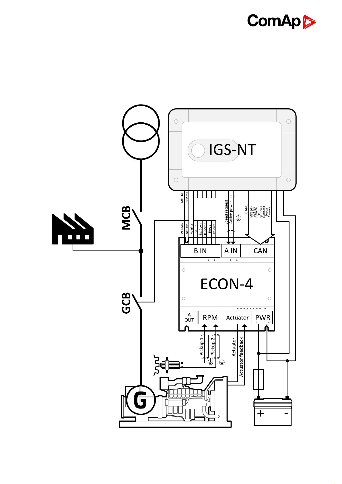
3.1 Wiring overview
6 back to Table of contents
ECON-4 1.4.0 GlobalGuide
8
Page 9

4 Installation and wiring
4.1 Package content 9
4.2 Module installation 10
4.3 Jumperposition 11
4.4 Recommendedwiring 12
6 back to Table of contents
4.1 Package content
The package contains:
ECON-4 module
Terminal blocks
ECON-4 1.4.0 GlobalGuide
9
Page 10
4.2 Module installation
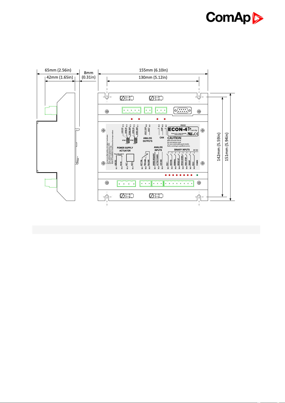
4.2.1 Dimensions and mounting
Image 4.1 Dimensions, terminals and mounting
Note: ECON-4 unit is mounted on DIN rail 35 mm.
ECON-4 1.4.0 GlobalGuide
10
Page 11

4.3 Jumper position
Jumper
P6
P7
P9
P10
Meaning
AOUT switch between current and voltage analogue output
Current: link the 2 pins fromright side
Voltage: link the 2 pins from left side
120 Ohm resistor for CAN line termination
Boot
Reset
ECON-4 1.4.0 GlobalGuide
11
Page 12
4.4 Recommended wiring
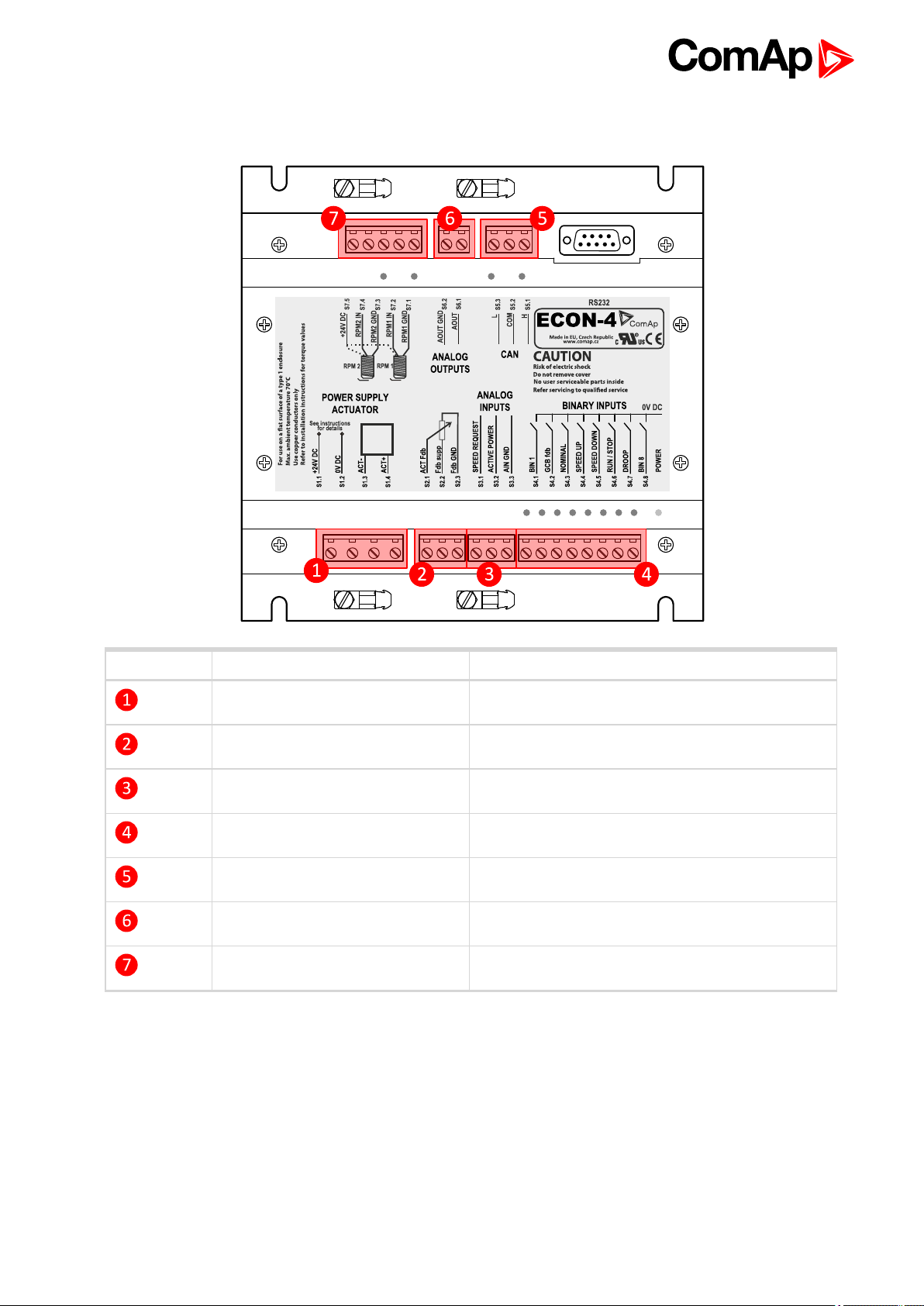
Postion Terminal groups Link
Power supply Actuators Power Supply (page 13)
Actuator feedback Interface to actuators (page 18)
Analog inputs Analog inputs (page 15)
Binary inputs Binary inputs (page 13)
Magnetick Pick-up Speed Pick-up (page 20)
Analog outputs Analog output (page 17)
Communications Communication wiring (page 20)
6 back to Installation and wiring
4.4.1 General
Use grounding terminals.
The “-“terminal of the battery has to be properly grounded.
Cables for binary inputs and analogue inputs must not be placed along power cables.
Analogueinputs should use shielded cables, especially when length >3m.
Always use shielded cable for Magnetic pick-up.
ECON-4 1.4.0 GlobalGuide
12
Page 13
4.4.2 Grounding
Use as short as possible cable to thegrounding point on the switchboard.
Use cable min. 2,5 mm2.
The “-“terminal of the battery has to be properly grounded.
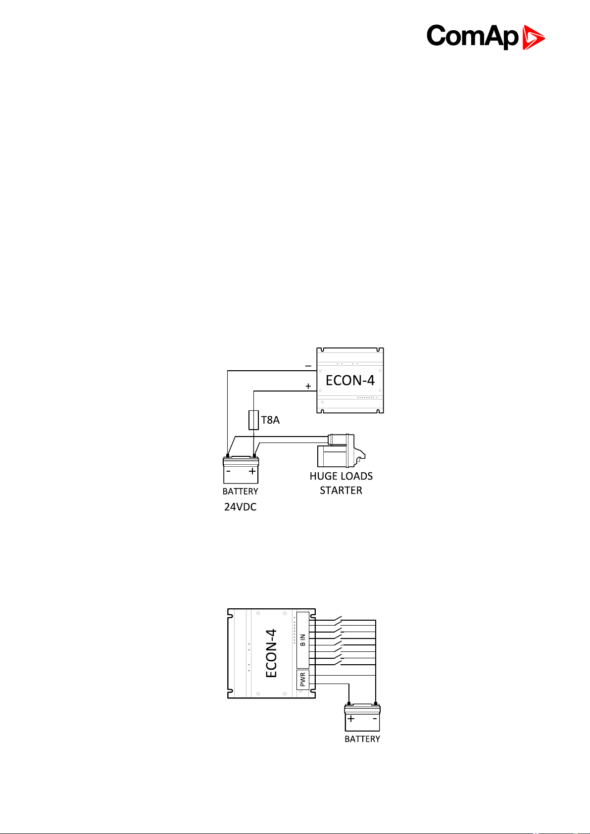
4.4.3 Power Supply
Use min. power supply cable of 4mm2.
Maximum continuous DC Power supplyvoltageis 36 V DC. Maximum short term allowable power supply
voltage is 39 V DC. The ECON-4’s power supply terminals are protected against large pulse power
disturbances. When there is a potential risk of the controller being subjected to conditions outside its
capabilities, an outside protection device should be used.
Power Supply Fusing
An eight-amp fuse should be connected in-line with the battery positive terminal to the controller andmodules.
ECON-4 should never be connected directly to the starting battery.
Recommended fuse is slow type– T8A.
4.4.4 Binary inputs
Binary inputs have internal load resistor 4.4 kΩ connected to the battery plus.
Image 4.2 Binary inputs wiring scheme
ECON-4 1.4.0 GlobalGuide
13
Page 14

Binary inputs are used to control the function of the ECON-4 digital governor.
Binary inputs can be read from:
the physical Binary inputs (terminals S4.x),
from the CAN-bus (byte Command in the Receive PDO),
in dependence on the value of thesetpoint Speed request.
Speed Request value CB Request value
Input
MCB fdb (S4.1) (page 14) MCB fd b
GCB fdb
NOMINAL
SPEED UP
SPEED DOWN
RUN / STOP
DROOP
RESERVE
BIN ANA DATA BIN DATA
S4.1 Cmd.1
S4.2 Cmd.2
S4.3 S4.3 Cmd.2
S4.4 X X
S4.5 X X
S4.6 S4.6
S4.7 S4.7 Cmd.4
S4.8
S4.6 &
Cmd.3
Note: Cmd.x is bit x in the byte Command of the Receive PDO, see description of CAN protocol. S4.x
isECON-4 terminal. Both the physical Binary input S4.6 and the corresponding bit Cmd.3 received via
CANbus must be active to activate Binary input RUN in DATA mode. In case of lost communication on
CANbus, all bits of the byte Command are set to 0 – it deactivates
MCB fdb (S4.1)
Inputs GCB andMCB fdb decide which setpoints are used in PID speed regulation loop and which type of
regulation is used (Iddle/Island/Parallel):
MCB
state
OFF OFF NO Speed gain, Speed int, Speed der
OFF OFF YES Speed gain, Speed int w, Speed der w
ON OFF NO Speed gain, Speed int, Speed der
ON OFF YES Speed gain, Speed int w, Speed der w
OFF ON - Load gain, Load int, Load der
ON ON - Load control according Speed/Fuel Line
GCB
state
lRPM - Requested RPMl > RPM window PID constants
Note: There is more Load gain and Load der values in ECON-4 ADV. Which set will be used depends on actuall
power.
GCB fdb (S4.2)
Inputs GCB andMCB fdb decide which setpoints are used in PID speed regulation loop and which type of
regulation is used (Iddle/Island/Parallel):
MCB
state
OFF OFF NO Speed gain, Speed int, Speed der
OFF OFF YES Speed gain, Speed int w, Speed der w
ON OFF NO Speed gain, Speed int, Speed der
GCB
state
lRPM - Requested RPMl > RPM window PID constants
ECON-4 1.4.0 GlobalGuide
14
Page 15

ON OFF YES Speed gain, Speed int w, Speed der w
OFF ON - Load gain, Load int, Load der
ON ON - Load control according Speed/Fuel Line
Note: There is more Load gain and Load der values in ECON-4 ADV. Which set will be used depends on actuall
power.
NOMINAL (S4.3)
The Required speed is set to Nominal RPM if the Nominal input is closed, otherwise is the Request set to Idle
RPM.
SPEED UP (S4.4)
Inputs SPEED UP and SPEED DOWN are used for setting of the speed reference of the engine. The speed
reference can be changed in the range from Nominal RPM - PerChSpdNom% to Nominal RPM +
PerChSpdNom%. Setpoint: EngineRPM:PerChSpdNom [1-20%] defines the maximum Percentage change of
Speed from Nominal in case BIN or ANA mode of control is used.
Setpoint BI Speed ramp decides how fast the speed reference changes, if the inputs SPEED UP or SPEED
DOWN are active.
Note: Inputs SPEED UP and SPEED DOWN are active only if the setpoint Speed request has value BIN.
SPEED DOWN (S4.5)
Inputs SPEED UP and SPEED DOWN are used for setting of the speed reference of the engine. The speed
reference can be changed in the range from Nominal RPM - PerChSpdNom% to Nominal RPM +
PerChSpdNom%. Setpoint: EngineRPM:PerChSpdNom [1-20%] defines the maximum Percentage change of
Speed from Nominal in case BIN or ANA mode of control is used.
Setpoint BI Speed ramp decides how fast the speed reference changes, if the inputs SPEED UP or SPEED
DOWN are active.
Note: Inputs SPEED UP and SPEED DOWN are active only if the setpoint Speed request has value BIN.
RUN (S4.6)
If the input is not active, governor immediately set the actuator to stop position.
DROOP (S4.7)
The input activates droop function – see setpoint Droop (page 62).
BIN 8 (S4.8)
BIN 8 is reserved for next functions.
4.4.5 Analog inputs
There are 2 analog inputs available on the ECON-4. Each of them can be configured either as 0-20mA or 0-10V
range by jumper setting – seein table below. The analoginput function is fixed.
ECON-4 1.4.0 GlobalGuide
15
Page 16

Range Recommended wiring Input Terminals Jumpers
SPEED REQUEST S3.1 P22 – 20 mA
0-20 mA
ACTIVE POWER S3.2 P23 – 20 mA
SPEED REQUEST S3.1 P22 – 10 V
0-10 V
ACTIVE POWER S3.2 P23 – 10 V
SPEED REQUEST (S3.1)
The input defines speedreference. It can be set in the range from Nominal RPM - PerChSpdNom% to Nominal
RPM + PerChSpdNom%. Setpoint: EngineRPM:PerChSpdNom [1-20%] defines the maximum Percentage
change of Speed from Nominal in case BIN or ANA mode of control is used.
Example: Analog input SPEED REQUEST is set to range 0 – 10 V, Nominal RPM is 1500 RPM, Input
voltage is 6 V. Speed reference is then ReqSpeed = 1500 + (PerChSpdNom/100)*1500*(6-5)/5 = 1524 RPM.
PerChSpdNom = 8 in the previous calculation.
Note: Input SPEED REQUEST is active only if the setpoint Speed request has value ANA.
ACTIVE POWER (S3.2)
Input from the external transmitter of Active power. Value of the Active power is used to improve load step
response of the governor. Input ACTIVE POWER is active only, if the setpoint Speed request has not value
DATA. The input sensitivity can be adjusted by setpoint Load anticip.
Note: Input ACTIVE POWER is active only if the setpoint Speed request has value BIN or ANA and setpoint
Load anticip > 0.
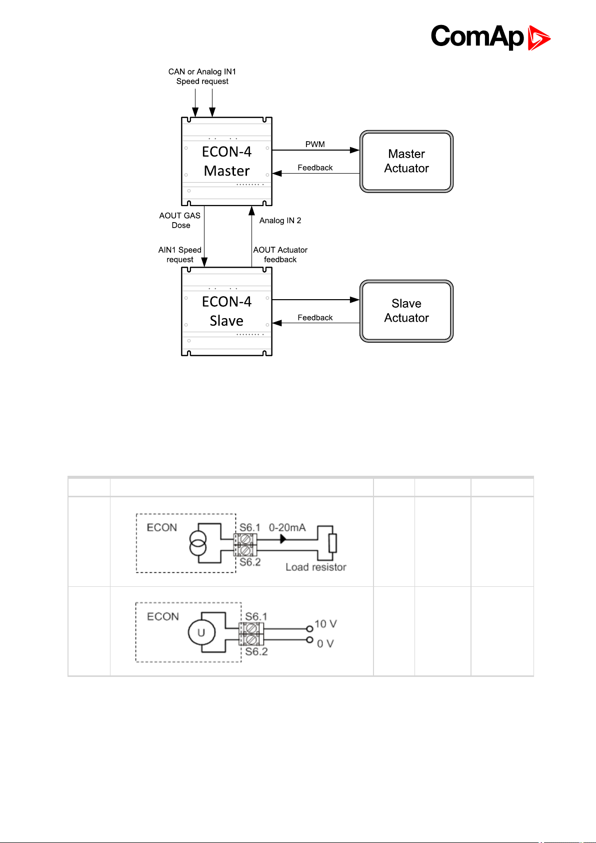
Collaboration with ECON-4Slave
Physical analog input on terminal S3.2 canbe used also when ECON4-Slave is used. In this case feedback
from slave actuator is put on analogue output on slave and can be connected back to masterto see it in one
Winscope (connected to master) and in controller thru CAN as Misf Angle.
Original Misf Angle calculation is not used in latest version of ECON4 and in version 1.4 is used to show
feedback from Slave. If feedback from slave is connected to analog input on S3.2 setpoint LoadAnticipationhas
to be =0. Othervise wrong value will be used forload anticip resulting unstability and unpredictive control
Principle of connection Master Slave is shown on next picture.
ECON-4 1.4.0 GlobalGuide
16
Page 17
4.4.6 Analog output
ECON-4 has one analogoutput configurable to 0-10V or 0-20mA range by jumper setting – see in table below. If
configuredto 0-20mA range, output works as an active current source. The analogoutput function is fix (copy of
the value sent to ACT output - GAS DOSE). Analogueoutput range is fully programmable in range 0-10V or 020mA – see setpoints: Analog settings: AOUT 0%and AOUT 100%.
Range Recommended wiring Output Terminals Jumpers
0-20
mA
0-10 V AOUT
AOUT
S6.1
S6.2
S6.1
S6.2
P6 - 20 mA
P6 - 10 V
Gas Dose (S6.1)
Output signal corresponds to actuator requested position. The limits are fully scaleablein range 0-10V (020mA).
E.g an actuator with input 4-20mA is used, theAOUT2 range setpoints should be adjusted in the following way:
ECON-4 1.4.0 GlobalGuide
17
Page 18

Analog sensors: AOUT2 0% = 20% (20% from 20mA = 4mA)
Analog sensors: AOUT2 100% = 100%
andjumper P6 adjusted to current option.
In case an actuator with an input 0-5V is used, the AOUT2 setpoints should be adjusted in the following way:
Analog sensors: AOUT2 0% = 0%
Analog sensors: AOUT2 100% = 50%
andjumper P6 adjusted to voltage option.
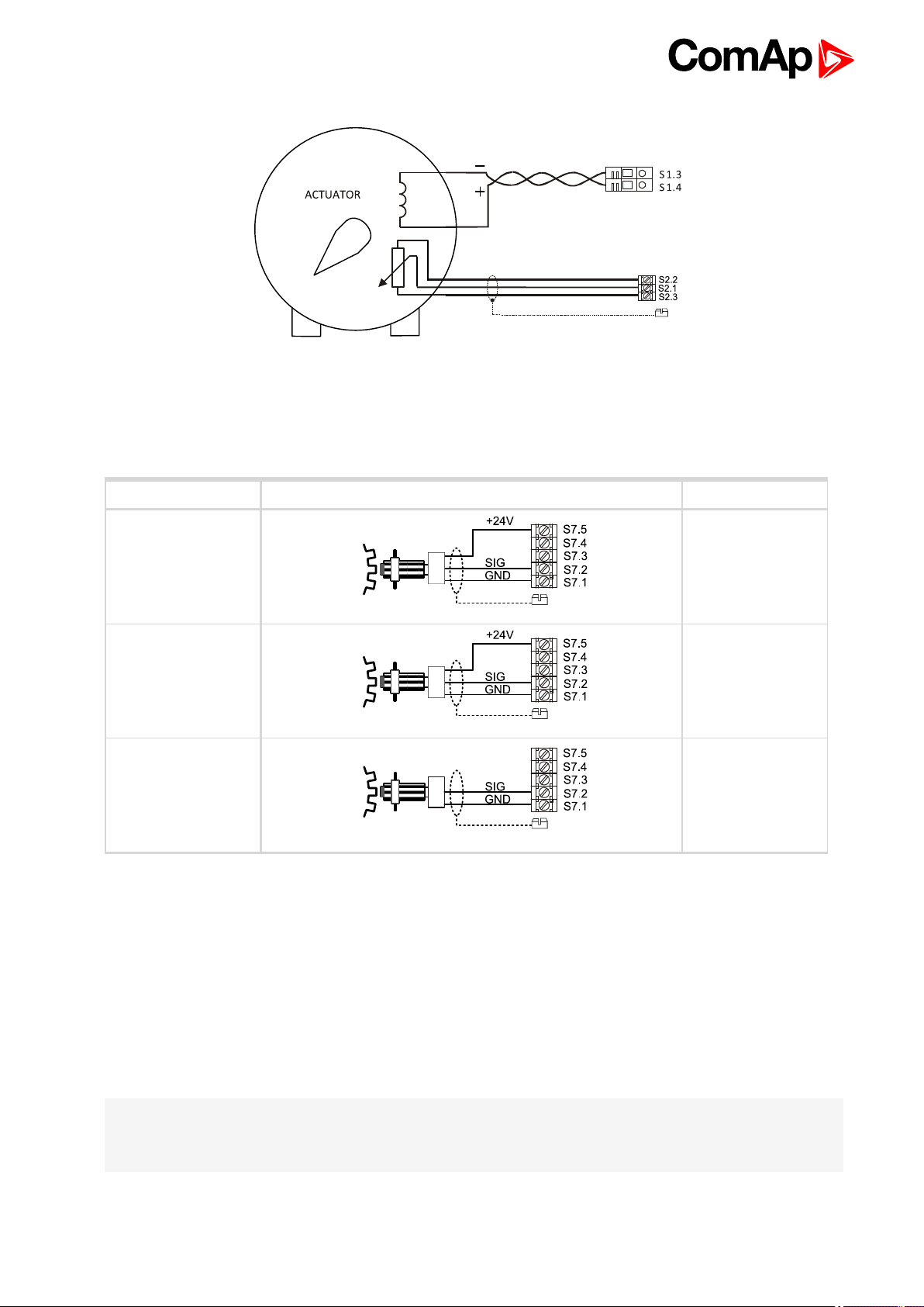
4.4.7 Interface to actuators
ECON-4 has one interface to actuator. The interface has a bipolar PWM output in bridge configuration and
position feedback input.
It is recommended to connect PWM output by a twisted cable and connect feedback input by a shielded cable.
Range Recommended wiring Terminals Jumpers
Ooutput
0 - 8 A
Feedback
0 - 5 V
Feedback
0 - 10 V
Types of actuators supported by ECON-4
With current input 200mA
Example: Typical example is Woodward UG-A.
S1.3 -
S2.2
S2.1
S2.3
S2.2
S2.1
S2.3
P21
P21
10V
5V
It is electro-hydraulic actuator – in principle a small electromagnetic actuator with hydraulic booster. It has
proportional characteristic – the bigger is the current, thebigger is the angle of the actuator, the polarity of the
current is not important. Actuatoris usually without electrical position feedback. For this actuator choose option
ActType: Wiring: LINEAR NO FEEDBACK
ECON-4 1.4.0 GlobalGuide
18
Page 19

With current input max. 10A
Example: Typical examples are actuators from GAC, Woodward Flowtech ITB.
It is electro-magnetic actuator with a strong return spring. This is in principle electromagnet with proportional
characteristic – the bigger is the current to the actuator, the bigger is the angle of the actuator. The polarity of the
current is not important. This type of actuator can be with or without position feedback. For this actuator choose
option ActType: Wiring: LINEAR or LINEAR NO FEEDBACK.
Motor driven actuators
Example: Typical examples are actuators from Heinzmann (STG 6, 10, 30, 2040.)
It is in principle a DC electromotor driving actuator lever. Since it is a motor, it has integrating characteristic – as
longas the current flows through the actuator, actuator’s lever moves. Direction of movement of the actuator
lever depends on polarity of the current. This typeof actuator has always position feedback. For this actuator
choose option ActTypex: Wiring: BRIDGE. For Heinzmann actuators, Jumper P21 – supply of the position
feedback must be set to option 0-10V. For Woodward and GAC actuators this jumper must be set to position 05V.
ECON-4 1.4.0 GlobalGuide
19
Page 20
4.4.8 Speed Pick-up
Always use a shieldedcable, connect shieldingto a grounding screw. ECON-4 supports both active (powered)
andpassive (magnetic) pickups.
Pick-up Recommended wiring Jumpers
Active NPN
Active PNP Link 1 and 2
Passive Link 2 and 3
If the jumper is in position 2-3, terminals GND and SIG areseparated from all other terminals. This enables to
share one pick-up by two modules, for instance by a speed governor and by an ignition, without danger of
creating a ground loop.
Link 1 and 2
Link 4 and 5
4.4.9 Communication wiring
CAN bus connection
ECON-4 is equipped by CAN communication line. CAN bus terminals are electrically isolated from any other
terminals.
Note: Following ECON-4 CAN setting is necessary to communicate with InteliSys NT:
CAN mode (Object number 10338) = 1 sets ComAp protocol
CAN NODE-ID (Object number10306) = 88 (decimal) sets address of the module
ECON-4 1.4.0 GlobalGuide
20
Page 21

Connection rules
CAN bus line must be connected in series, from one unit to the next (no star, no cable stubs, and no branches)
both ends must be by the 120-ohm (internal or external) resistorterminated. Maximal CAN bus length is 200
meters.
ECON-4 contains internal 120-ohm resistor, connected through a removable jumper P7.
For CAN data cables details seechapter Technical data – Communication interface. CAN cable shielding
connect to CAN COM terminal.
6 back to Recommended wiring
ECON-4 1.4.0 GlobalGuide
21
Page 22

5 ECON-4 setup
5.1 Quick start - how to set ECON4 andcontroller 22
5.2 Entering password 28
5.3 Data 28
5.4 ECON-4 configuration and PC tools 32
5.5 ECON adjustement for various types of actuators 34
5.6 Detailed fucntion 37
6 back to Table of contents
5.1 Quick start - how to set ECON4 and controller
The following description should help you to quick adjust the ECON-4speed governor. The ECON-4 can be
found in different modes used for control of moduleand engine.
Basically any input signal of ECON4 can be suppliedeither using wired signal or using data from CAN1 line.
Input signals of ECON4 areseparated in to two groups each group can be controlled in different way.
Group Setpoint Signal
Breaker`s
feedback
Speed control
Block schema where data flow in different modes is shown is located in Setpoints section CB request (page 50)
andSpeed request (page 49)
There is separated description of setting for different modes for CB request and Speed request on following
pages.
CB
request
Speed
request
GCB feedback
MCB feedback
Speed request analogue signal
Actual power analogue signal
SpeedUp and SpeedDown binary
signal
Idle/Nominal binary signal
Droop binary signal
RUN binary signal
Possible control
mode
BIN/ANA/DATA
BIN/DATA
5.1.1 Breakers feedback handling (CB request modes)
CB request set to BIN mode
Image 5.1 CB request - BIN mode
ECON-4 1.4.0 GlobalGuide
22
Page 23

In case of binary control of breaker`s feedback, signals from breakers has to be wired to terminals S4.1 and
S4.2. You do not needto link any source to Binary outputs of ECON4 in Genconfig.
CB request set to DATA mode
Image 5.2 CB request - DATA mode
In case of DATA control of breaker`s feedback, logical signals from breakers has to be linked to Binary outputs
of ECON4 in Genconfig. Terminals S4.1 and S4.2. do not need to be wired.
5.1.2 Speed control handling (Speed request modes)
Speed request set to ANA mode
Image 5.3 Speed request - ANA mode
ECON-4 1.4.0 GlobalGuide
23
Page 24

In case of ANAlogue mode, the required speed is controlled via Analogue input S3.1 (voltage or current signal,
connected between terminals S3.1 and S3.3). The binary control signals (Idle/Nominal, Run/Stop, Droop) are
evaluated from the binary terminals S4.3 – S4.8 as in case of BINary mode.
In case the source of the Analogue input Speedrequest to ECON-4 is ComAp controller (e.g. InteliSysNT),
adjust the ComAp setpoints in the following way:
Sync/Load ctrl: SpeedGov Bias = 5 Volts (for 1500 RPM sets)
Sync/Load ctrl: SpeedGovLoLim = 0 Volts
Sync/Load ctrl: SpeedGovHiLim = 10 Volts
Sync/Load ctrl: Freq gain = 5 %
Sync/Load ctrl: Freq int = 5 %
Sync/Load ctrl: Angle gain= 10 %
You do not need to link any source to Binary outputs of ECON4 in Genconfig. This type of control can be used
with firmwarewithout support of ECON4 or even for collaboration with thirt party controlleror without any
controller just as standalone speed controller (no Data communication to ECON4 is needed).
Necessary signal – RPM signal – connected to RPM1 terminal – S7.2 and S7.1
Speed request set to BIN mode
Image 5.4 Speed request - BIN mode
In case of BINary control, the ECON-4 is fully controlled via binary inputs – terminals S4.3 – S4.8.(except CB
control). The input S4.6 is the ON/OFF signal to ECON-4, in case it is not active, speed governor will not open
the throttle. In case it is deactivated during engine running, throttle is immediately closed. Use BIN S4.3 to
switch from Idle running to Nominal speedrunning (Idle and Nominal speedadjustment is in ECON-4 setpoints:
Engine RPM). Do not put the Idle RPM and Nominal RPM to the same value. In case you want engine to be
running at Nominal RPM without Idle period, leave BIN S4.3 activated all the time.
Use BIN S4.4 and S4.5 (SpeedUP and Speed Down) to control the speed or load (in case of parallel with mains
operation).
You do not need to link any source to Binary outputs of ECON4 in Genconfig. This type of control can be used
with firmwarewithout support of ECON4 or even for collaboration with thirt party controlleror without any
controller just as standalone speed controller (no Data communication to ECON4 is needed).
Necessary signal – RPM signal – connected to RPM1 terminal – S7.2 and S7.1
Speed request set to DATA mode
In case of DATA control almost all the data can be sent from ComAp IGS-NT controllers to ECON-4 via CAN1
line. The only binary input RUN/STOP – S4.6 must be activated physically as well. To use theDATA mode,
adjust the IGS-NT inputs/outputs in thefollowing way:
ECON-4 1.4.0 GlobalGuide
24
Page 25

a. Configurationof ECON-4 module
Go to GenConfig, card Modules – Extension modules – Others – ECON-4 > Insert
b. Configurationof Binary outputs of IGS-NT
All the ECON-4inputs are in fact IGS-NT outputs (IGS-NT controller sends the signals to ECON-4 unit).
BO1 – this configuration of feedback is independent andis described in previous chapter Breaker`s
feedback handling (CB request modes)
BO2 – this configuration of feedback is independent andis described in previous chapter Breaker`s
feedback handling (CB request modes)
BO3– Idle/Nominal – configure on this output signal which defines switching from Idle operation to Nominal
ROM run. The Logbout signal: Idle/Nominal of IGS-NT canbe used. In case the Idle period is required to be
skipped, configure on this output signal Log bout: Logical 1.
BO4 – Run Stop – together with binary input S4.6 RUN/STOP this signal must be activated to unblock
ECON-4 function. Signal Log Bout: Fuel solenoid can be used.
BO5 – Droop – use the Droop function in case of in Mains parallel operation to make the load control function
more stable (protectagainst power swing). Use signal e.g. GCB feedback.
ECON-4 1.4.0 GlobalGuide
25
Page 26

BO1 and2 setting is separated and described in previous chapter
c. Configuration of Analogue inputs from IGS-NTto ECON-4 (those are signals from ECON4 to controller, in
ourconfiguration it is namedfrom controllers point of view, so inputs)
AIN1 – Engine RPM
The engine RPM can be sent from ECON-4 into the IS-NT via CAN line as well. Configure the AIN1 in the
following way:
Function – RPM pick-up
Sensor– Electronic
the IGS-NT controller.
d. Configurationof Analogue outputs from IGS-NT to ECON-4
AOUT1 – Active Power Rel
ECON-4 is equipped with the Load anticipationfunction to react as quickly as possible to the sudden
changes of the engine power. For this function ECON-4 needs information about power and in case of DATA
mode this can be sent to ECON-4 via CAN. Adjust theAOUT1 in the following way:
Source: Genervalues: ActPwr rel
Normalize: YES
Resolution: 0,1
AOUT2 – Speed RequestThe Speed request in case of DATA mode is sent via CAN line. Configure the
output AOUT2 in the following way:
Source: Sync.
ECON-4 1.4.0 GlobalGuide
26
Page 27

Load ctrl: SpeedReqRPM
IMPORTANT: Configuration of Analog output AOUT2from IS2GASXX to ECON-4 has to be
configured as SpeedReqRPMx8
Controller setting in case ECON4 is set to communicate with controller via CAN1 (Speed request set to DATA
mode)
Besides the above mentioned inputs/outputs adjustment, the IGS-NT setpoints shall be adjusted in the
following way:
Sync/Load ctrl: SpeedGov Bias = 0 Volts
Sync/Load ctrl: SpeedGovLoLim = -10 Volts
Sync/Load ctrl: SpeedGovHiLim = 10 Volts
Sync/Load ctrl: Freq gain = 5 %
Sync/Load ctrl: Freq int = 5 %
Sync/Load ctrl: Angle gain= 10 %
IMPORTANT: Please, take in account, there are several setpoints of ECON-4, which are not
accessible via IGS-NT control unit in case of DATA mode. These parameters are crucial for ECON-4
and used Actuator adjustment and so these are accessible via ECON-4 connection ONLY. Use
ComAp PC sw WinScope to adjust these setpoints.
For all modes of ECON-4 usage adjust
Type of used Actuator – Main PID: Actuator type, PWM rate. The ACT1-4 are preadjusted, see: Act type 1 –
predefined forWoodwardITB 0-200mA, PWM rate [Hz].Speed PID loop – MAIN PID: Speed gain= 10%,
Speed Int = 10%, Speed der = 40%Type of ECON-4 communication mode: Engine RPM: Speed RequestIdle,
Nominal, Overspeed RPM: Engine RPM: Idle RPM, Nominal RPM, Overspeed.
ECON-4 1.4.0 GlobalGuide
27
Page 28

5.2 Entering password
5.2.1 Modify password from WinScope
WinScope PCprogram is used for modifying Setpoints.
Enter password
Password is a four-digit number. Password enables to change set points from WinScope PC program. Use icon
to activate a dialog box for password.
Change password
Use icon to activate a dialog box for password change. The password has to be entered to activated this
icon.
5.2.2 Modify password from GenConfig
Certain Setpoints can be modified directly from GenConfigPCtool. For information how to enter password in
GenConfig please see GenConfig Global Guide.
5.3 Data
Followingdata arecommunicated between IS-NT (specific sw branches only) and ECON-4 via CAN bus.
Correct function depends on configuration by PC GenConfig software.
5.3.1 Data Binary inputs
Followingdata from ECON-4 can be used for states indication or alarms activation.
ECON-4 Name Function
BI1 Bin1 Physical input state, reserve
BI2 Bin2 GCB Fdbck Physical input state
BI3 Bin3 Nominal Physical input state
BI4 Bin4 SpeedUp Physical input state
BI5 Bin5 SpeedDown Physical input state
BI6 Bin6 Run/Stop Physical input state
BI7 Bin7 Droop Physical input state
BI8 Bin8 Physical input state, reserve
BI9 Reserve
BI10 Reserve
BI11 Engine running ECON-4 state indication
BI12 OverSpeed Sd ECON-4 state indication
BI13 PID limit Fuel is on limit
ECON-4 1.4.0 GlobalGuide
28
Page 29

BI14 ActFdbErr Active actuatorfeedback error
BI15 ActOverldProt Active overload protection
BI16 InvalSetpoints Setpoints CRC fail
5.3.2 Data Binary outputs
ECON-4 accepts the data from InteliSys-NT (specific sw branches only) instead from Physical Binary inputs,
when setpoint Engine RPM: Speed request = DATA.
ECON-4
BO1 MCB feedback
BO2 GCB feedback
BO3 Nominal
BO4 Run/StopÂÂ
BO5 Droop
Name
The physical RUN/STOP – S5.6 binary input must be closed in any type of control to run ECON-4 i.e. in “DATA
mode” together with data commandBO4 Run/Stop to enable speed control function (unblock the actuator from
0% position).
5.3.3 Data Analog inputs
ECON-4 Name Logical function
AI1 Engine RPM
AI2 Misfiring Amplitude
1
No RPM pickup is needed in IS-NT. Configure IS-NT – I /O – ECON-4– AIN1 Engine RPM for
Function = RPM pick-up
RPM pick-up;
(RPM value source forIS-NT)
Sensor= Electronic
5.3.4 Data Analog outputs
ECON-4 Name Function
AOUT1 Active power - relative 0,0 - 100,0 % (option)
AOUT2 SpeedReq RPM In RPM/8 (option)
Active power value is required for Load anticipationfunction – see Main PID: Load anticip. In GenConfig choose
value: Gener values: Act Pwr rel, option Normalize – YES, resolution 0,1.
For AOUT2 choose: Sync/Load ctrl: SpeedReqRPM and leave the default settings of this output.
5.3.5 ECON adjustement for various types of actuators
Basically there are available 3 types of actuator types:
LINEAR – actuator is driven by a current, which acts against a spring which pushes the actuator to close
position. Actuator is equipped with position feedback signal. Available feedback signal for ECON is 0,4 to
4,6 Volts DC.
1
Misfiring evaluation from ECON-4 is not implemented in version 1.0
ECON-4 1.4.0 GlobalGuide
29
Page 30

LINEAR NO FDB – actuator is driven by a current, which acts against a spring which pushes the actuator
to close position. Actuatoris not equipped with position feedback signal.
BRIDGE – in principal electromotor, one current polarity moves the actuator to one position, reverse polarity
moves the actuator to another position.
Adjustment for LINEAR actuator type (typically Woodward
A. At first check the position feedback level, in case it is not within limits 0.4 to 4,6 Volts, then use the LINEAR
NO FDB adjustment.
B. Connect to ECON-4 via USB connector, using PC program WinScope.
C. Adjust the Position feedback limits in parameter group: AnalogSensors: Fdb 0 pos to voltage of feedback in
case the actuator is fully closed, and Fdb 100 pos to value of voltage when actuator is fully opened.
D. ECON-4 does not measure the current through actuator. The output signal is PWM, with adjustable
frequency. The maximum ECON-4 current is given by resistance of the actuator and power supply of
ECON-4. ECON-4 is rated to maximum 8 Amps. In case the actuator has resistance 32 Ohms and power
supply is 24V, then maximum ECON-4 current is: 24/32 = 0,75A = 750mA. This means 100% of ECON
current is 750mA. In case the maximum allowable actuator current is 250mA, then this is 33.3% of
maximum ECON-4 current. This value will be used for the maximum current limitation.
E. Choose one ActType x group, e.g. ActType 1 and adjust parameter Wiring to LINEAR, and adjust
parameters Act gain to 10%, Act int to 10% and Act der to 10%
F. Parameters: ActTypex (In this case ActType 1): ActCur 0% and ActCur 100% are not used, so their value is
not important
G. Parameters: ActTypex (In this case ActType 1): Act MaxCur is maximum allowable current, in case bigger
current is detected (in fact bigger output PWM signal is detected)for longer then: ActMaxCurDel, then the
output is limited to value ActReduced Cur. So in case we have actuator with resistance 32Ohms, ECON
powersupply is 24Volts and maximum allowable actuator is 250mA, then it is recommendedto adjust: Act
MaxCur = 33,3%, (24V / 32Ω = 750mA, 250mA is 33,3% from 750mA), Act MaxCurDel = 5 sec, Act
ReducedCur = 10%.
H. Adjust parameter: Main PID: ActuatorType to the actuator which youuse, so in this case ActType 1.
I. Connect the actuator to ECON-4, outputs ACT+ ACT- (take care about polarity)
J. Adjust ECON-4 parameter: Main PID: ECON-4 mode to MANUAL and run WinScope recording with values:
Gas Dose and Act1 Fdbck in range 0.0 – 100.0%.
K. When recording is active, change parameter: Main PID: Act position from 0 to 10, 20, 30, .. 100 and check
the response of the actuator (via feedback signal in WinScope). In case theresponse is too lazy or too fast,
then update thecorresponding Act gain, Act int and Act der parameters in ActTypex (in ourcase ActType1)
to get required response.
L. After adjustment is finished, put parameter: Main PID: ECON-4 mode to AUTOMATIC
M. Based on the chosen type of control (BIN, ANA, DATA) connect the required signal
N. Adjust all other parameters like Nominal, Idle speed, Geer teeth, Overspeed, Speed and Load PID, (to the
number which ECON-4 output you areusing)
O. ECON-4 is ready forstart attempt.
Adjustment for LINEAR NO FDB actuator type (typically GAC, Woodward)
A. Connect to ECON-4 via USB connector, using PC program WinScope.
B. Choose one ActType x group, e.g. ActType 1 and adjust parameter Wiring to LINEAR NO FDB
ECON-4 1.4.0 GlobalGuide
30
Page 31

C. ECON-4 does not measure the current through actuator. The output signal is PWM, with frequency 6000 Hz.
The maximum ECON-4current is given by resistance of the actuator and power supply of ECON-4. ECON4 is ratedto maximum 8 Amps. In case the actuator has resistance 32 Ohms and power supply is 24V, then
maximum ECON-4 current is: 24/32 = 0,75A = 750mA. This means 100% of ECON current is 750mA. In
case the maximum allowable actuator current is 250mA, then this is 33.3% of maximum ECON-4current.
Adjust Act Cur0% to 0% and Act Cur 100% to 34% (250mA from 750mA). By this the output is scaled from
0 to 250 mA.
D. Parameters: ActTypex (In this case ActType 1): Act MaxCur is maximum allowable current, in case bigger
current is detected (in fact bigger output PWM signal is detected)for longer then: ActMaxCurDel, then the
output is limited to value ActReduced Cur. The Act Max Curr is calculated from the value Act Cur 100%, so
it means, that the current limitation is in this case already done by adjustment of ActCur 100%, and Act Max
Cur shall be adjusted to 100%. Act MaxCurDel and ActReducedCur then can be adjusted to any value.
E. Parameters: ActTypex ()ActType 1 in this case) Act gain, Act int, Act der has no meaning for the LINEAR
NO FDB adjustment.
F. Adjust parameter: Main PID: Actuator Type to theactuator which you use, so in this case ActType 1.
G. Connect the actuator to ECON-4, outputs ACT+ ACT- (take care about polarity)
H. Adjust ECON-4 parameter: Main PID: ECON-4 mode to MANUAL andrun WinScope recordingwith values:
Gas Dose and Act1 Fdbck in range 0.0 – 100.0%.
I. After adjustment is finished, put parameter: Main PID: ECON-4 mode to AUTOMATIC
J. Based on the chosen type of control (BIN, ANA, DATA) connect the requiredsignal
K. Adjust all other parameters like Nominal, Idle speed, Geer teeth, Overspeed, Speedand Load PID,
ActChannel (to the number which ECON-4 output you areusing)
L. ECON-4 is ready for start attempt.
Adjustment for BRIDGE actuator type (typically Heinzmann)
A. At first check the position feedback level, in case it is not within limits 0.4 to 4.6 Volts, then the bridge
actuator cannot be controlledwith ECON.
B. Connect to ECON-4 via USB connector, using PC program WinScope.
C. Adjust the Position feedback limits in: AnalogSensors: Fdb 0 pos to voltageof feedback in case the actuator
is fully closed, and Fdb 100pos to value of voltage when actuator is fully opened.
D. Choose one ActType x group, e.g. ActType1
E. ECON-4does not measure the current through actuator. The output signal is PWM, with frequency 6000Hz.
The maximum ECON-4current is given by resistance of the actuator and power supply of ECON-4. ECON4 is ratedto maximum 8 Amps. In case the actuator has resistance 2,5 Ohms and power supply is 24V, then
maximum ECON-4 current is: 24/2.5 = 9,6A but ECON max allowable current is 8 Amps!! So the output
must be limited. This means 100% of ECON theoretical current is 9,6A. In case the maximum allowable
actuator current is 5A, then this is 52% of maximum ECON-4 theoretical current. This value will be used for
the maximum current limitation. So adjust ActType1: Act Max Cur = 52%, Act Max Cur Del = 5 sec and Act
ReducedCur = e.g. 20%.
In case bigger current is detected (in fact bigger output PWM signal is detected) forlonger then:
ActMaxCurDel, then the output is limited to value ActReduced Cur.
F. Adjust parameter Wiring to BRIDGE, and adjust parameters Act gain to 10%, Act int to 10% and Act der to
10%
ECON-4 1.4.0 GlobalGuide
31
Page 32

G. Parameters: ActTypex (In this case ActType 1): ActCur 0% and ActCur 100% are not used, so their value is
not important
H. Adjust parameter: Main PID: ActuatorType to the actuator which youuse, so in this case ActType 1.
I. Connect the actuator to ECON-4, outputs ACT+ ACT- (take care about polarity!!)
J. Adjust ECON-4 parameter: Main PID: ECON-4 mode to MANUAL and run WinScope recording with values:
Gas Dose and Act1 Fdbck in range 0.0 – 100.0%.
K. When recording is active, change parameter: Main PID: Act position from 0 to 10, 20, 30, .. 100 and check
the response of the actuator (via feedback signal in WinScope). In case theresponse is too lazy or too fast,
then update thecorresponding Act gain, Act int and Act der parameters in ActTypex (in ourcase ActType1)
to get required response.
L. After adjustment is finished, put parameter: Main PID: ECON-4 mode to AUTOMATIC
M. Based on the chosen type of control (BIN, ANA, DATA) connect the required signal
N. Adjust all other parameters like Nominal, Idle speed, Geer teeth, Overspeed, Speed and Load PID,
ActChannel (to the number which ECON-4 output you areusing)
O. ECON-4 is ready forstart attempt.
5.4 ECON-4 configuration and PC tools
5.4.1 Setpoints adjustements in WinScope SW:
Connect RS232 port on your PC to RS232 port on ECON-4. Open connection and select Controller type
EMCON5, ECON-3, INCON, RailCon, select your RS232 com port and press OK
Image 5.5 Direct connection of WinScope SW to ECON-4
Then open setpoint Tab and work with setpoints. For rest of operations (channel selection, trend recording...)
see manual for WinScope SW.
Click on the iconSetpoints to open the Setpoints groups. To be able to change any setpoints, the password
has to adjust at first (otherwise the setpoints are grayed andcannot be changed).
ECON-4 1.4.0 GlobalGuide
32
Page 33

5.4.2 Econ-4 firmware update
For ECON-4 firmware upgrade use ComAp FlashProgrammer – see below, choose card ECON-4 (common for
ECON-4). Tick the button Program and choose theappropriate firmware using icon “Locate…”
You can save your setpoints from an existing site andprogram them together with the new firmware. However
the program change does not influence the setpoints, so you can keep them in ECON-4.
Choose theright COM port number and press “Start” button.
Hint:
ECON-4 1.4.0 GlobalGuide
33
Page 34

To be able to program ECON-4 using the FlashProg, you must be disconnected with the WinScope or
InteliMonitor from ECON-4. (There can be always only one active connection to ECON-4 through com port)
5.5 ECON adjustement for various types of actuators
Basically there are available 3 types of actuator types:
LINEAR – actuator is driven by a current, which acts against a spring which pushes the actuator to close
position. Actuator is equipped with position feedback signal. Available feedback signal for ECON is 0,4 to
4,6 Volts DC.
LINEAR NO FDB – actuator is driven by a current, which acts against a spring which pushes the actuator
to close position. Actuatoris not equipped with position feedback signal.
BRIDGE – in principal electromotor, one current polarity moves the actuator to one position, reverse polarity
moves the actuator to another position.
5.5.1 Adjustment for LINEAR actuator type (typically Woodward
A. At first check the position feedback level, in case it is not within limits 0.4 to 4,6 Volts, then use the LINEAR
NO FDB adjustment.
B. Connect to ECON-4 via USB connector, using PC program WinScope.
C. Adjust the Position feedback limits in parameter group: AnalogSensors: Fdb 0 pos to voltage of feedback in
case the actuator is fully closed, and Fdb 100 pos to value of voltage when actuator is fully opened.
D. ECON-4 does not measure the current through actuator. The output signal is PWM, with adjustable
frequency. The maximum ECON-4 current is given by resistance of the actuator and power supply of
ECON-4. ECON-4 is rated to maximum 8 Amps. In case the actuator has resistance 32 Ohms and power
supply is 24V, then maximum ECON-4 current is: 24/32 = 0,75A = 750mA. This means 100% of ECON
current is 750mA. In case the maximum allowable actuator current is 250mA, then this is 33.3% of
maximum ECON-4 current. This value will be used for the maximum current limitation.
E. Choose one ActType x group, e.g. ActType 1 and adjust parameter Wiring to LINEAR, and adjust
parameters Act gain to 10%, Act int to 10% and Act der to 10%
F. Parameters: ActTypex (In this case ActType 1): ActCur 0% and ActCur 100% are not used, so their value is
not important
G. Parameters: ActTypex (In this case ActType 1): Act MaxCur is maximum allowable current, in case bigger
current is detected (in fact bigger output PWM signal is detected)for longer then: ActMaxCurDel, then the
output is limited to value ActReduced Cur. So in case we have actuator with resistance 32Ohms, ECON
powersupply is 24Volts and maximum allowable actuator is 250mA, then it is recommendedto adjust: Act
MaxCur = 33,3%, (24V / 32Ω = 750mA, 250mA is 33,3% from 750mA), Act MaxCurDel = 5 sec, Act
ReducedCur = 10%.
H. Adjust parameter: Main PID: ActuatorType to the actuator which youuse, so in this case ActType 1.
I. Connect the actuator to ECON-4, outputs ACT+ ACT- (take care about polarity)
J. Adjust ECON-4 parameter: Main PID: ECON-4 mode to MANUAL and run WinScope recording with values:
Gas Dose and Act1 Fdbck in range 0.0 – 100.0%.
K. When recording is active, change parameter: Main PID: Act position from 0 to 10, 20, 30, .. 100 and check
the response of the actuator (via feedback signal in WinScope). In case theresponse is too lazy or too fast,
ECON-4 1.4.0 GlobalGuide
34
Page 35

then update thecorresponding Act gain, Act int and Act der parameters in ActTypex (in ourcase ActType1)
to get required response.
L. After adjustment is finished, put parameter: Main PID: ECON-4 mode to AUTOMATIC
M. Based on the chosen type of control (BIN, ANA, DATA) connect the required signal
N. Adjust all other parameters like Nominal, Idle speed, Geer teeth, Overspeed, Speed and Load PID, (to the
number which ECON-4 output you areusing)
O. ECON-4 is ready forstart attempt.
5.5.2 Adjustment for LINEAR NO FDB actuator type (typically GAC, Woodward)
A. Connect to ECON-4 via USB connector, using PC program WinScope.
B. Choose one ActType x group, e.g. ActType 1 and adjust parameter Wiring to LINEAR NO FDB
C. ECON-4 does not measure the current through actuator. The output signal is PWM, with frequency 6000 Hz.
The maximum ECON-4current is given by resistance of the actuator and power supply of ECON-4. ECON4 is ratedto maximum 8 Amps. In case the actuator has resistance 32 Ohms and power supply is 24V, then
maximum ECON-4 current is: 24/32 = 0,75A = 750mA. This means 100% of ECON current is 750mA. In
case the maximum allowable actuator current is 250mA, then this is 33.3% of maximum ECON-4current.
Adjust Act Cur0% to 0% and Act Cur 100% to 34% (250mA from 750mA). By this the output is scaled from
0 to 250 mA.
D. Parameters: ActTypex (In this case ActType 1): Act MaxCur is maximum allowable current, in case bigger
current is detected (in fact bigger output PWM signal is detected)for longer then: ActMaxCurDel, then the
output is limited to value ActReduced Cur. The Act Max Curr is calculated from the value Act Cur 100%, so
it means, that the current limitation is in this case already done by adjustment of ActCur 100%, and Act Max
Cur shall be adjusted to 100%. Act MaxCurDel and ActReducedCur then can be adjusted to any value.
E. Parameters: ActTypex ()ActType 1 in this case) Act gain, Act int, Act der has no meaning for the LINEAR
NO FDB adjustment.
F. Adjust parameter: Main PID: Actuator Type to theactuator which you use, so in this case ActType 1.
G. Connect the actuator to ECON-4, outputs ACT+ ACT- (take care about polarity)
H. Adjust ECON-4 parameter: Main PID: ECON-4 mode to MANUAL andrun WinScope recordingwith values:
Gas Dose and Act1 Fdbck in range 0.0 – 100.0%.
I. After adjustment is finished, put parameter: Main PID: ECON-4 mode to AUTOMATIC
J. Based on the chosen type of control (BIN, ANA, DATA) connect the requiredsignal
K. Adjust all other parameters like Nominal, Idle speed, Geer teeth, Overspeed, Speedand Load PID,
ActChannel (to the number which ECON-4 output you areusing)
L. ECON-4 is ready for start attempt.
5.5.3 Adjustment for BRIDGE actuator type (typically Heinzmann)
A. At first check the position feedback level, in case it is not within limits 0.4 to 4.6 Volts, then the bridge
actuator cannot be controlledwith ECON.
B. Connect to ECON-4 via USB connector, using PC program WinScope.
ECON-4 1.4.0 GlobalGuide
35
Page 36

C. Adjust the Position feedback limits in: AnalogSensors: Fdb 0 pos to voltageof feedback in case the actuator
is fully closed, and Fdb 100pos to value of voltage when actuator is fully opened.
D. Choose one ActType x group, e.g. ActType1
E. ECON-4does not measure the current through actuator. The output signal is PWM, with frequency 6000Hz.
The maximum ECON-4current is given by resistance of the actuator and power supply of ECON-4. ECON4 is ratedto maximum 8 Amps. In case the actuator has resistance 2,5 Ohms and power supply is 24V, then
maximum ECON-4 current is: 24/2.5 = 9,6A but ECON max allowable current is 8 Amps!! So the output
must be limited. This means 100% of ECON theoretical current is 9,6A. In case the maximum allowable
actuator current is 5A, then this is 52% of maximum ECON-4 theoretical current. This value will be used for
the maximum current limitation. So adjust ActType1: Act Max Cur = 52%, Act Max Cur Del = 5 sec and Act
ReducedCur = e.g. 20%.
In case bigger current is detected (in fact bigger output PWM signal is detected) forlonger then:
ActMaxCurDel, then the output is limited to value ActReduced Cur.
F. Adjust parameter Wiring to BRIDGE, and adjust parameters Act gain to 10%, Act int to 10% and Act der to
10%
G. Parameters: ActTypex (In this case ActType 1): ActCur 0% and ActCur 100% are not used, so their value is
not important
H. Adjust parameter: Main PID: ActuatorType to the actuator which youuse, so in this case ActType 1.
I. Connect the actuator to ECON-4, outputs ACT+ ACT- (take care about polarity!!)
J. Adjust ECON-4 parameter: Main PID: ECON-4 mode to MANUAL and run WinScope recording with values:
Gas Dose and Act1 Fdbck in range 0.0 – 100.0%.
K. When recording is active, change parameter: Main PID: Act position from 0 to 10, 20, 30, .. 100 and check
the response of the actuator (via feedback signal in WinScope). In case theresponse is too lazy or too fast,
then update thecorresponding Act gain, Act int and Act der parameters in ActTypex (in ourcase ActType1)
to get required response.
L. After adjustment is finished, put parameter: Main PID: ECON-4 mode to AUTOMATIC
M. Based on the chosen type of control (BIN, ANA, DATA) connect the required signal
N. Adjust all other parameters like Nominal, Idle speed, Geer teeth, Overspeed, Speed and Load PID,
ActChannel (to the number which ECON-4 output you areusing)
O. ECON-4 is ready forstart attempt.
ECON-4 1.4.0 GlobalGuide
36
Page 37

5.6 Detailed fucntion
5.6.1 Block schematics - speed governor
Overspeed protection in ECON4-ADV
Instead of value in the middle between Nominal and Overspeed thereis additional RPM level defined in setpoint
Engine RPM: PreOverSpeed in ECON4-ADV versions. When RPM reaches this level, Gas Dose Value
(throttle position) goes to value in setpoint Engine RPM: PreOverSpReduct – can be set to Idle Fuel or Close.
This feature was added to prevent overspeedwhen Load is removed – typically switch off large load in island
operation.
Overspeed protection
In case the actual RPM crosses RPM value: Engine RPM: Overspeed, then the Gas Dose is immediately
forced to the zero – throttle is closed and shutdown is issued.
There is proactive action taken to try to keep engine running without shutdown, when actual RPM reaches value
in the middle between Nominal and Overspeed value. In this case, when RPM crosses this middle value, Gas
Dose is set to Idle position and when RPM drops back below this middlevalue, speed PID will continue to
regulate RPM.
Purpose of this behavior is to prevent the Overspeed situation by detecting the RPM increase and step change
of the fuel (closing the fuel). As the RPM are dropping down subsequently towards the Nominal RPM the fuel is
ECON-4 1.4.0 GlobalGuide
37
Page 38

changed again to maintain the RPM on Nominal value andnot to cause a dip in the RPM.
Speed governor function in Idle or local load mode
ECON-4 compares the Reference and Actual speeds of the engine and calculates theRegulation error.
The Actual speed is measured from the period of the signal generated by the magnetic pickup sensing gears of
the flywheel.
Speed reference canbe generated by 3 ways:
by Binary inputs,
by Analogue input
from CAN bus,
For more information see setpointSpeed request (page 49).
The Regulation error is then processed by the standard PID control structure with proportional, integration and
derivative parts. The PID setpoints – Gain, Int andDer define the quality of regulation.
The parameters of the PID control structure are different if the engine is in:
no-load operation,
loaded operation
For more information see setpoint .Description (page 53)
The output of the PID control structure is then added together with the Load anticipation feedback, which is
directly proportional to the engine power. The output from the last sum is limited by the Anti-windup Limiter
module, which reduces the integrator’s output signal so that the sum of the signals from the Gain, Integrator,
Differentiator and Loadanticipation blocks equals exactly the limit MaxFuel.
Speed governor function in parallel mode
When engineis in parallel to Mains, Econ4 works just as amplifierand converts Speed request signal to Gas
Dose signal according Speed/Fuel line as follows
ECON-4 1.4.0 GlobalGuide
38
Page 39

Transition to parallel from zero local load.
When engineis running without load, speed request from controller is in bias position and enginehas a throttle in
Idle position. So if those values are properly set in to ECON4 setpoints while going to parallel, engine startso to
runin SGO Bias and IdleFuel point on Speed/Fuel line. When request for load is increased in controller, Speed
request is increased andthrottle is opened and vice versa.
Transition to parallel from non-zero local load.
There could be situation in SPtm for example, when just GCB is closed and generator supply a local load. So
MCB is opened and GCB is closed and PID with Load parameters is used to control speedand Throttle position.
It is clear than Throttle is not in Idle position but on higher position. Now after synchronization, MCB is closed,
throttle stays in the same position because no Higher Power is generated just after synchronization and Actual
speed request is in Bias position because no power control has been done in previous stage. So there is
difference betweenactual speed request andspeed request corresponding to actual throttle position. This
difference is called Speed request offset and we keep it to make transition burpless. When controller increase
aped request to provide more powerto Mains, we move throttle to higher position on the Speed/fuel line andit
works fine. But we cannot keep speed request offset all time, because when controller decrease speed request
throttle would go to zero position and even to negative value (theoretically). So we keep Speed request offset
just for one minute from breaker closing and then starts to decrease this offset. This will move throttle down, but
controller will notify decreasing of power and increase speed request. After a while, using this mechanism
Speed request offset oi zero and actual throttle position respects speedrequest and Speed/fuel line.
Speed request offset is decreased according ramp, which is set in setpoint SGOoffsetRamp. Time in this
setpoint is time needed to change Speed request offset from 10V to 0V.
6 back to ECON-4 setup
ECON-4 1.4.0 GlobalGuide
39
Page 40

6 Communication
6.1 Connection to ECON-4
Connect RS232 cable and start WinScope software. Click on the Connection, Open Connection and choose
Direct connection type, EmCon5, ECON-4, INCON Controller type, choose the right COM port and press O.K.
button.
6 back to Table of contents
ECON-4 1.4.0 GlobalGuide
40
Page 41

7 Technical data
Actuator feedback input
Resolution
Analog inputs
Number
Resolution
Rang e
Analog measurement
tolerance
Analog outputs
Number
Resolution
Rang e
Analog measurement
tolerance
Binary inputs
Number
Input resistance
Input range
Switching voltage level for close con tact
indication
Max voltage level for open contact indication
10 bits non electrically separated
2 non electrically separated
10 bits
0 - 10 V; input resistance 11 kΩ
0 - 20 mA; load resistor 50 Ω
1 %
1 non electrically separated
0 - 100000
0 - 10 V; output resistance < 1 kΩ
0 - 20 mA; Active current source
1 %
8
4.4 kΩ
0 - 36 V DC
0 - 2 V
8 - 36 V
CAN bus interface
Maximal CAN bus length
Speed
Nominal impedan ce
Cable type
General information
Weight
Protect ion
Operating conditions
Operating temperature
Storage temperature
Humidity
Low voltage directive
Electromagnetic
compatibility
Vibratio ns
Shocks
200 m galvanically separated
250 kBd
120 Ω
twisted pair (shielded)
600 g
IP20
- 30 to +70 ˚C
-30 to +80˚C
95% without condensation
EN 61010-1:95 +A1:97
EN 50081-1:94, EN 50081-2:96
EN 50082-1:99, EN 50082-2:97
5 - 25 Hz, ± 1,6mm 25 - 100 Hz, a = 4 g
a = 200 m/s
2
ECON-4 1.4.0 GlobalGuide
41
Page 42

Power supply
Power supply rang e
Con sumption
RS232 interface
Maximal distance
Speed
Speed pick-up inputs
Type of sensor
Minimum input voltage
Maximum input voltage
Minimum measured
frequ ency
Maximum measured
frequ ency
Frequency measurement
tolerance
6 back to Table of contents
12-36 V DC
0,5 – 10 A, depends on supply voltage and used actuator
10 m
19 200 bps
Active or magnetic pick-up (connection by shielded cable is strongly recommended)
2 Vpk-pk (from 4 Hz to 4 kHz)
50 Veff
4 Hz
10 kHz (min. input voltage 6Vpk-pk)
0,2 %
ECON-4 1.4.0 GlobalGuide
42
Page 43

8 Appendix
8.1 Setpoints 44
6 back to Table of contents
ECON-4 1.4.0 GlobalGuide
43
Page 44

8.1 Setpoints
What setpoints are:Setpoints are analog, binary or special data objects which are used for adjusting the
controller to the specific environment. Setpoints are organized into groups according to their meaning. Setpoints
can be adjusted from the controller front panel, PC, MODBUS, etc. All setpoints canbe protected by a
password against unauthorized changes. Password protection can be assigned to thesetpoints during the
configurationprocedure.
See the chapter Entering password (page 28)forthe instructions how to enter and modify a password.
IMPORTANT: Setpoints are organized in logical groups for better orientation. Use WinScope or
InteliMonitor software to modify the setpoints. For details see chapter ECON-4 configuration and
PC tools (page 32)
8.1.1 List of setpoint groups
8.1.3 Group: Engine StartGroup: ECON4-EngRPM 46
8.1.4 Group: Engine StartGroup: ECON4-EngStart 51
8.1.5 Group: Main PIDGroup: ECON-4-MainPID 53
8.1.6 Act type1 – predefined for Woodward ITB 0-200 mA 69
8.1.7 Act type2 – predefined for Woodward ITB PWM 71
8.1.8 Act type3 –predefined for Woodward F-series PWM 71
8.1.9 Act type4 – predefined for Heinzmann STG 10 72
8.1.10 Group: Analog sensors 72
8.1.11 List of tested actuators by ComAp 74
For full list of Setpoints go to the chapter List of setpoints (page 45).
ECON-4 1.4.0 GlobalGuide
44
Page 45

8.1.2 List of
Group of setpoints:
setpoints
Group of setpoints:
Engine RPM
PreOverSpeed 50
PreOverSpReduct 51
Group of setpoints:
Engine Start
Group of setpoints:
Main PID
RPM Window 55
Speed int w 55
Speed der w 55
Load anticip 58
ActType 1,2,3,4
Act gain 69
Act int 69
Act der 69
Act MaxCur 70
ActmaxCurDel 70
Act ReducedCur 70
Wiring 71
6 back to Setpoints
Load 1 59
Load 2 60
Load 3 61
Load 4 62
LAder+limit 67
LAder-limit 67
LAder+ 67
LAder- 68
LAder+recover 68
LAder-recover 68
Group of setpoints:
Analog sensors
LoReqSpeed Inp 72
HiReqSpeed Inp 72
AOUT 0 73
AOUT 100 73
FBD 0 pos 73
FBD 100 pos 74
ECON-4 1.4.0 GlobalGuide
45
Page 46

8.1.3 Group: Engine StartGroup: ECON4-EngRPM
Idle RPM
1.4.0
Setpoint group Engine RPM Related FW
Range [units] Start RPM - Nominal RPM
Default value 1000 RPM Force value NO
Step 1 RPM
Comm object 7186 Related applications ALL
Description
Engine idle speed.
6 back to List of setpoints
Nominal RPM
Setpoint group Engine RPM Related FW
configuredECON-4 extension
module
1.4.0
configuredECON-4 extension
module
Range [units] 0 - 2500[RPM]
Default value 1500 RPM Force value NO
Step 1 RPM
Comm object 7187 Related applications ALL
Setpoint visibility Always
Description
Nominal enginespeed.
6 back to List of setpoints
Overspeed
1.4.0
Setpoint group Engine RPM Related FW
Range [units] 0 - 2500[RPM]
Default value 1800 RPM Force value NO
Step 1 RPM
Comm object 7168 Related applications ALL
configuredECON-4 extension
module
Setpoint visibility Always
Description
Maximum acceptable speed of the engine. If the actual engine speed is higher, ECON-4 immediately closes
the actuator. Normal function is restored after detection of zero engine speed.
6 back to List of setpoints
ECON-4 1.4.0 GlobalGuide
46
Page 47

Gear teeth
1.4.0
Setpoint group Engine RPM Related FW
Range [units] 32 - 400 [-]
Default value 256 Force value NO
Step 1
Comm object 7188 Related applications ALL
Setpoint visibility Always
Description
Number of teeth on the engine gear for the pick-up.
6 back to List of setpoints
configuredECON-4 extension
module
Idle-Nom ramp
1.4.0
Setpoint group Engine RPM Related FW
Range [units] 0 - 100 [s]
configuredECON-4 extension
module
Default value 10 s Force value NO
Step 1 s
Comm object 7169 Related applications ALL
Setpoint visibility Always
Description
Define how fast changes therequested enginespeed during transition from Idle RPM (page 46) to Nominal
RPM (page 46) and vice versa. Idle-Nom ramp is directly time that theramp needs to go from Idle RPM (page
46) to Nominal RPM (page 46) and vice versa. The ramping speedis the same for both up anddown
directions.
6 back to List of setpoints
ECON-4 1.4.0 GlobalGuide
47
Page 48

BI Speed ramp
1.4.0
Setpoint group Engine RPM Related FW
Range [units] 1.0 - 100.0 [s]
Default value 50 s Force value NO
Step 1.0 s
Comm object 7170 Related applications ALL
Setpoint visibility Always
Description
Define how fast changes therequested enginespeed if the binary inputs SPEED UP or SPEED DOWN are
active. BI Speed ramp is actually time that the ramp needs to go from Nominal RPM (page 46) - 8%
toNominal RPM (page 46) + 8% and vice versa. The ramping speed is the same for both up anddown
directions.
6 back to List of setpoints
configuredECON-4 extension
module
ECON-4 1.4.0 GlobalGuide
48
Page 49

Speed request
1.4.0
Setpoint group Engine RPM Related FW
Range [units] BIN, ANA, DATA
Default value DATA Force value NO
Step -
Comm object 7171 Related applications ALL
Setpoint visibility Always
Description
The setpoint defines source of the Speed reference of the engine.
Speed Request value Speed reference source
BIN SPEED UP, SPEED DOWN
ANA SPEED REQUEST
DATA CAN bus
configuredECON-4 extension
module
Speed request - BIN
Speed request - ANA Speed request - DATA
6 back to List of setpoints
ECON-4 1.4.0 GlobalGuide
49
Page 50

CB request
1.4.0
Setpoint group Engine RPM Related FW
Range [units] BIN / DATA
Default value DATA Force value NO
Step -
Comm object 14363 Related applications ALL
Setpoint visibility Always
Description
CB Request value CB position information source
BIN Terminal S4.1 and S4.2
DATA CAN bus
Note: If possible, use binary control for CB request and wire terminal S4.1 and S4.2 to feedback signal.
This will assure fastest reaction of ECON4 when breaker is closed or opened. This is crucial to avoid
over speed in case of opening GCB under load for example.
configuredECON-4
extension module
6 back to List of setpoints
PreOverSpeed
1.4.0
Setpoint group Main PID Related FW
Range [units] Nominal RPM – Overspeed RPM
Default value 1750 Force value NO
Step 1 RPM
Comm object 14408 Related applications ALL
Setpoint visibility WinScope only
Description
When actual RPM reaches this value Gas Dose (throttle position) is immediately set to Idle Fuel value or
zero (closed position) accordingsettingin setpoint PreOverSpReduct .
6 back to List of setpoints
ECON-4 1.4.0 GlobalGuide
configuredECON-4
ADVextension module
50
Page 51

PerChSpdNom
1.4.0
Setpoint group Engine RPM Related FW
Range [units] 1 - 20 [%]
Default value 8 % Force value NO
Step 1 %
Comm object 7193 Related applications ALL
Setpoint visibility Always
Description
Percentage Change of Requested RPM from Nominal RPM. This setpoint defines the maximum allowable
change of requested RPM from the Nominal RPM value in case the BIN or ANA control of RPM is used.
Use this setpoint to enlarge maximum allowable swingof the required RPM. Setpoint is by default adjusted
to 8% which should fulfill the most of installations.
6 back to List of setpoints
configuredECON-4 extension
module
PreOverSpReduct
1.4.0
Setpoint group Main PID Related FW
configuredECON-4
ADVextension module
Range [units] IDLE FUEL – CLOSE
Default value - Force value NO
Step -
Comm object 14409 Related applications ALL
Setpoint visibility WinScope only
Description
Value set to output GAS Dose when RPM reaches value in setpoint PreOverSpeed.
6 back to List of setpoints
8.1.4 Group: Engine StartGroup: ECON4-EngStart
InitStart dose
Setpoint group Engine RPM Related FW 1.4.0
Range [units] Start RPM - Nominal RPM
Default value 10% Force value NO
Step 1 %
Comm object 7172 Related applications ALL
Setpoint visibility Always
Description
Initial position of the actuator during start
6 back to List of setpoints
ECON-4 1.4.0 GlobalGuide
51
Page 52

MaxStart dose
Setpoint group Engine RPM Related FW 1.4.0
Range [units] Start RPM - Nominal RPM
Default value 50% Force value NO
Step 1 %
Comm object 7173 Related applications ALL
Setpoint visibility Always
Description
Maximum position of the actuator during start.
6 back to List of setpoints
Fuel ramp time
Setpoint group Engine RPM Related FW 1.4.0
Range [units] Start RPM - Nominal RPM
Default value 10 s Force value NO
Step 1 s
Comm object 7174 Related applications ALL
Setpoint visibility Always
Description
Time the actuator needs to move from the InitStart dose to MaxStart dose.
6 back to List of setpoints
RPM StartRamp
Setpoint group Engine RPM Related FW 1.4.0
Range [units] Start RPM - Nominal RPM
Default value 10 s Force value NO
Step 1 s
Comm object 7175 Related applications ALL
Setpoint visibility Always
Description
This setpoint defines speedof ramp from Starting RPM to Idle RPM. It is directly the time of ramp from.
6 back to List of setpoints
ECON-4 1.4.0 GlobalGuide
52
Page 53

Starting RPM
Setpoint group Engine RPM Related FW 1.4.0
Range [units] Start RPM - Nominal RPM
Default value 350 RPM Force value NO
Step 1 RPM
Comm object 7189 Related applications ALL
Setpoint visibility Always
Description
If ECON-4 detects speedhigher then Starting RPM, it terminates thestarting sequence end starts normal
speed regulation.
Note: ECON-4 can work only if Starting RPM < Idle RPM < Nominal RPM. If this condition is not met, ECON-4
activates bit Invalid setpoints in Transmit PDO 1, see description of CAN protocol. It is not possible to run the
engine if the bit Invalid setpoint is signalized.
6 back to List of setpoints
8.1.5 Group: Main PIDGroup: ECON-4-MainPID
Speed gain
1.4.0
Setpoint group Main PID Related FW
Range [units] 0.0 – 200.0 %
Default value 10% Force value NO
Step 0.1 %
Comm object 7176 Related applications ALL
Setpoint visibility Always
Description
Gain of the PID speed regulation loop.
Note: Setpoint is active for unloaded engine.
6 back to List of setpoints
configuredECON-4 extension
module
ECON-4 1.4.0 GlobalGuide
53
Page 54

Speed int
1.4.0
Setpoint group Main PID Related FW
Range [units] 0.0 – 100.0 %
Default value 10% Force value NO
Step 0.1 %
Comm object 7177 Related applications ALL
Setpoint visibility Always
Description
Integration of the PID speed regulation loop..
Note: Setpoint is active for unloaded engine.
6 back to List of setpoints
configuredECON-4 extension
module
Speed der
1.4.0
Setpoint group Main PID Related FW
configuredECON-4 extension
module
Range [units] 0.0 – 100.0 %
Default value 0% Force value NO
Step 0.1 %
Comm object 7178 Related applications ALL
Setpoint visibility Always
Description
Derivative part of thePID speed regulation loop.
Note: Setpoint is active for unloaded engine.
6 back to List of setpoints
ECON-4 1.4.0 GlobalGuide
54
Page 55

RPM Window
1.4.0
Setpoint group Main PID Related FW
Range [units] -
Default value - Force value NO
Step -
Comm object 12091 Related applications ALL
Setpoint visibility WinScope only
Description
In case the actual RPM differs from Requested RPM for more than RPM window [RPM], the Speed PID
constants fluently change from Speed int to Speed int w and from Speed der to Speed der w. The aim of the
RPM window is to changethe speed of regulation(reaction) in case the actual RPM differs significantly from
Requested RPM.
6 back to List of setpoints
configuredECON-4 extension
module
Speed int w
1.4.0
Setpoint group Main PID Related FW
configuredECON-4 extension
module
Range [units] 0-100 %
Default value 10% Force value NO
Step 1 %
Comm object 12092 Related applications ALL
Setpoint visibility WinScope only
Description
Integration part of the PID regulation loop in case theactual RPM differs from Requested RPM for more than
RPM window.
6 back to List of setpoints
Speed der w
1.4.0
Setpoint group Main PID Related FW
Range [units] 0,0-100,0 %
Default value 0% Force value NO
Step 0.1 %
configuredECON-4 extension
module
Comm object 12176 Related applications ALL
Setpoint visibility WinScope only
Description
Derivative part of thePID regulation loop in case the actual RPM differs from Requested RPM for more than
RPM window..
ECON-4 1.4.0 GlobalGuide
55
Page 56

6 back to List of setpoints
Load gain
1.4.0
Setpoint group Main PID Related FW
Range [units] 0.0 – 200.0 %
Default value 10% Force value NO
Step 0.1 %
Comm object 7179 Related applications ALL
Setpoint visibility Always
Description
Gain of the PID speed regulation loop.
There is 5 different setpoints Load gain:
Load gain 1
Load gain 2
Load gain 3
Load gain 4
configuredECON-4 extension
module
For more information about Load der setting please see Load 1 (page 59) ECON-4 Global Guide.
6 back to List of setpoints
Load der
1.4.0
Setpoint group Main PID Related FW
Range [units] 0.0 – 100.0 %
Default value 0% Force value NO
Step 0.1 %
Comm object 7181 Related applications ALL
Setpoint visibility Always
Description
Derivative part of thePID speed regulation loop.
There is 5 different setpoints Load der:
Load der 1
Load der 2
configuredECON-4 extension
module
Load der 3
Load der 4
For more information about Load der setting please see Load 1 (page 59) ECON-4 Global Guide.
6 back to List of setpoints
ECON-4 1.4.0 GlobalGuide
56
Page 57

Load Int
1.4.0
Setpoint group Main PID Related FW
Range [units] 0.0 – 100.0 %
Default value 10% Force value NO
Step 0.1 %
Comm object 7180 Related applications ALL
Setpoint visibility Always
Description
Integration of the PID speed regulation loop.
There is 5 different setpoints Load Int:
Load Int 1
Load Int 2
Load Int 3
Load Int 4
For more information about Load Int setting please see Load 1 (page 59) ECON-4 Global Guide.
configuredECON-4 extension
module
6 back to List of setpoints
ECON-4 1.4.0 GlobalGuide
57
Page 58

Load anticip
Setpoanticip
group
Range [units] 0.0 - 100.0 [%]
Default value 0% Force value NO
Step 0.1 %
Comm object 11102 Related applications ALL
Setpoanticip
visibility
Description
Governor is equipped by load anticipation feedback, which helps to keep stable speed in case of fast load
changes. In thecase of load jump forces the ECON-4governoroutput (Actuator lever) by jump according to
Load anticip setting.
Engine load value can be received via physical Analog input S3.2 ACTIVE POWER as 0 to 10V or 20 mA
signal (if setpoanticip Speed request=BIN or ANA) or via CAN bus in the case of communication to IS-NT
controller (if setpoanticip Speed request=DATA). In such case follow this configuration in GenConfig: /
I/O – Analog outputs – ECON-4 – AOUT1 = Gener values – Act.power rel.
In the configuration choose optionNormalize – YES and resolutionadjust to 0,1
Main PID Related FW
WinScope only
1.4.0
configuredECON-4 extension
module
There is 5 different setpoanticips Load anticip:
Load anticip 1
Load anticip 2
Load anticip 3
Load anticip 4
For more information about Load anticip setting please seeLoad 1 (page 59).
6 back to List of setpoints
ECON-4 1.4.0 GlobalGuide
58
Page 59

Load 1
1.4.0
Setpoint group Main PID Related FW
Range [units] 0 – 100.0 %
Default value 20% Force value NO
Step 0.1 %
Comm object 13979 Related applications ALL
Setpoint visibility WinScope only
Description
There is 5 load bands defined via setpoints Load 1 to Load 5 and different Load gain, Load Int, Load der and
Load anticip setpoints are active in each band.
configuredECON-4
ADVextension module
6 back to List of setpoints
ECON-4 1.4.0 GlobalGuide
59
Page 60

Load 2
1.4.0
Setpoint group Main PID Related FW
Range [units] 0 – 100.0 %
Default value 40% Force value NO
Step 0.1 %
Comm object 13980 Related applications ALL
Setpoint visibility WinScope only
Description
There is 5 load bands defined via setpoints Load 1 to Load 5 and different Load gain, Load Int, Load der and
Load anticip setpoints are active in each band.
configuredECON-4
ADVextension module
6 back to List of setpoints
ECON-4 1.4.0 GlobalGuide
60
Page 61

Load 3
1.4.0
Setpoint group Main PID Related FW
Range [units] 0 – 100.0 %
Default value 60% Force value NO
Step 0.1 %
Comm object 13981 Related applications ALL
Setpoint visibility WinScope only
Description
There is 5 load bands defined via setpoints Load 1 to Load 5 and different Load gain, Load Int, Load der and
Load anticip setpoints are active in each band.
configuredECON-4
ADVextension module
6 back to List of setpoints
ECON-4 1.4.0 GlobalGuide
61
Page 62

Load 4
1.4.0
Setpoint group Main PID Related FW
Range [units] 0 – 100.0 %
Default value 80% Force value NO
Step 0.1 %
Comm object 13982 Related applications ALL
Setpoint visibility WinScope only
Description
There is 5 load bands defined via setpoints Load 1 to Load 5 and different Load gain, Load Int, Load der and
Load anticip setpoints are active in each band.
configuredECON-4
ADVextension module
6 back to List of setpoints
Droop
1.4.0
Setpoint group Main PID Related FW
Range [units] 0.0 - 100.0 [%]
Default value 0% Force value NO
Step 0.1 %
Comm object 7182 Related applications ALL
Setpoint visibility Always
Description
Droop of speed governor. The governor lovers the speed reference by Droop percent of the Nominal RPM
(page 46) over the range from zero to MaxFuel (page 63).
6 back to List of setpoints
configuredECON-4 extension
module
ECON-4 1.4.0 GlobalGuide
62
Page 63

MaxFuel
1.4.0
Setpoint group Main PID Related FW
Range [units] 0.0 – 100.0 %
Default value 100% Force value NO
Step 0.1 %
Comm object 7184 Related applications ALL
Setpoint visibility Always
Description
Maximum output from the PID speed control loop + Load anticipationsignal. It limits the maximum fuel
delivered to theengine.
Note: It is also used as coordinate for Speed/Fuel line. See description in chapter Speed governor function in
parallel mode.
6 back to List of setpoints
configuredECON-4 extension
module
IdleFuel
1.4.0
Setpoint group Main PID Related FW
Range [units] 0.0 – 100.0 %
Default value 10% Force value NO
Step 0.1 %
Comm object 7192 Related applications ALL
Setpoint visibility Always
Description
IdleFuel is base (togetherwith MaxFuel) for Droop function calculation..
Note: Set this setpoint after engine is running on Nominal speed (no load) according to the real position of
Actuator lever
6 back to List of setpoints
configuredECON-4 extension
module
ECON-4 1.4.0 GlobalGuide
63
Page 64

Actuator type
1.4.0
Setpoint group Main PID Related FW
Range [units] -
Default value ActType1 Force value NO
Step -
Comm object 7185 Related applications ALL
Setpoint visibility Always
Description
ECON-4 can be connected to various types of actuators. Setpoints of the internal actuator feedback loop are
tuned for the common actuators and predefinedfrom the factory. Normally there is no need to change them.
The user must only choose the right Actuator type. By default the ActType 1 is chosen. Check thetypeof
your actuator and compare with the predefined type.
6 back to List of setpoints
configuredECON-4 extension
module
ECON-4 mode
1.4.0
Setpoint group Main PID Related FW
configuredECON-4 extension
module
Range [units] -
Default value AUTO Force value NO
Step -
Comm object 7190 Related applications ALL
Setpoint visibility Always
Description
ECON-4 must be in AUTO for normal operation. ModeMAN can be used during installation to check the
function of the actuator and linkage. If ECON-4 is in MAN mode, it sets the actuator to position Act position.
It can be switched to MAN mode only any time even engine is running. This allows measurement of
transition curve to calculate PID parameters.
Note: ECON-4 when engine is running set the same value to setpoint Act position as position where throttle is.
It assure bump less transition.
IMPORTANT: Even Overspeed protection is active in all modes, be carefull when setting throttle
position manualy. Engine can accelerate when breaker opens or when throttle position is too
high.Make sure ECON-4 mode is in Auto positon before you leave installation.
6 back to List of setpoints
ECON-4 1.4.0 GlobalGuide
64
Page 65

Act position
1.4.0
Setpoint group Main PID Related FW
Range [units] 0.0 – 100.0 %
Default value 30% Force value NO
Step 0.1 %
Comm object 7191 Related applications ALL
Setpoint visibility Always
Description
Adjusts the actuator position in the Econ-4 Mode = MAN.
6 back to List of setpoints
configuredECON-4
extension module
PWM rate
1.4.0
Setpoint group Main PID Related FW
Range [units] 500– 10 000 Hz
configuredECON-4 extension
module
Default value 6000 Hz Force value NO
Step 1 Hz
Comm object 7194 Related applications ALL
Setpoint visibility Always
Description
Frequency of the PWM signal sent to ACT+ and ACT- outputs..
Note: For Heinzmann actuators adjust the PWM rate to 6000 Hz. For Woodward PWM and current, GAC
actuators adjust the PWM rate to 2000Hz.
6 back to List of setpoints
SGO Bias
1.4.0
Setpoint group Main PID Related FW
Range [units] ± 10 V
Default value 0.00 V Force value NO
Step 0.01V
configuredECON-4 extension
module
Comm object 14375 Related applications ALL
Setpoint visibility [[[Undefined variableSpecific.WinScopeOnly]]]
Description
Togetherwith Idle Fuel value creates coordinates for first point of Speed/Fuel line. For detailed description
seesee Speed governor function in parallel mode on page 38 ECON-4 Global Guide.
Note: Setpoint is active for unloaded engine.
ECON-4 1.4.0 GlobalGuide
65
Page 66

6 back to List of setpoints
SGO HiLim
1.4.0
Setpoint group Main PID Related FW
Range [units] ± 10 V
Default value 10.00 V Force value NO
Step 0.01V
Comm object 14376 Related applications ALL
Setpoint visibility [[[Undefined variableSpecific.WinScopeOnly]]]
Description
Togetherwith Max Fuel value creates coordinates for second point of Speed/Fuel line. For detailed
description see see Speed governor function in parallel mode on page 38ECON-4 Global Guide
Note: Setpoint is active for unloaded engine.
6 back to List of setpoints
configuredECON-4 extension
module
SGOoffsetRamp
1.4.0
Setpoint group Main PID Related FW
Range [units] 10 - 1800 s
Default value 30 s Force value NO
Step 1 s
Comm object 14375 Related applications ALL
Setpoint visibility [[[Undefined variableSpecific.WinScopeOnly]]]
Description
This defines rampaccording SGOoffset is removed after parallel. For details see chapter Speed governor
function in network parallel mode see see Speed governor function in parallel mode on page 38 ECON-
4 Global Guide.
Note: Setpoint is active for unloaded engine.
6 back to List of setpoints
configuredECON-4 extension
module
ECON-4 1.4.0 GlobalGuide
66
Page 67

LAder+limit
1.4.0
Setpoint group Main PID Related FW
Range [units] 0 – 100.0 %
Default value 5% Force value NO
Step 0.1 %
Comm object 14402 Related applications ALL
Setpoint visibility WinScope only
Description
Limit on Load stepin + direction, changes bellow this limit will not generate any derivation
6 back to List of setpoints
configuredECON-4
ADVextension module
LAder-limit
1.4.0
Setpoint group Main PID Related FW
Range [units] 0 – 100.0 %
configuredECON-4
ADVextension module
Default value 5% Force value NO
Step 0.1 %
Comm object 14405 Related applications ALL
Setpoint visibility WinScope only
Description
Limit on Load stepin – direction, changes bellow this limit will not generate any derivation
6 back to List of setpoints
LAder+
1.4.0
Setpoint group Main PID Related FW
Range [units] 0 – 100.0 %
Default value 0% Force value NO
Step 1 %
Comm object 14403 Related applications ALL
Setpoint visibility WinScope only
configuredECON-4
ADVextension module
Description
Amount of derivation when Load increases
6 back to List of setpoints
ECON-4 1.4.0 GlobalGuide
67
Page 68

LAder-
1.4.0
Setpoint group Main PID Related FW
Range [units] 0 – 100.0 %
Default value 0% Force value NO
Step 1 %
Comm object 14406 Related applications ALL
Setpoint visibility WinScope only
Description
Amount of derivation when Load decreases
6 back to List of setpoints
configuredECON-4
ADVextension module
LAder+recover
1.4.0
Setpoint group Main PID Related FW
Range [units] 1.01 – 10.00 %
configuredECON-4
ADVextension module
Default value 10 Force value NO
Step 0.01%
Comm object 14404 Related applications ALL
Setpoint visibility WinScope only
Description
Derivation curve definition – drop from + value. Initial value is divided by this numberrepeatedly once per
0.1s. So higher value means faster drop to zero.
6 back to List of setpoints
LAder-recover
1.4.0
Setpoint group Main PID Related FW
Range [units] 1.01 – 10.00 %
Default value 10 Force value NO
Step 0.01%
Comm object 14407 Related applications ALL
configuredECON-4
ADVextension module
Setpoint visibility WinScope only
Description
Derivation curve definition – drop from - value. Initial value is divided by this number repeatedly once per
0.1s. So higher value means faster drop to zero.
6 back to List of setpoints
ECON-4 1.4.0 GlobalGuide
68
Page 69

8.1.6 Act type 1 – predefined for Woodward ITB 0-200 mA
There are 4 identical groups of setpoints in ECON-4. They are used to setupthe output circuits for particular
types of actuators andtune the actuator position PID loop.
Note: Normally these Actuator type setpoints are predefined from the factory and there is no need to readjust
them. Modify them if you have a non-standard, or non listed actuator only – see List of tested actuators by
ComAp on page 74
Act gain
Setpoint group ActType1,2,3,4 Related FW 1.4.0
Range [units] 0.0 – 1000.0 [%]
Default value 50% Force value NO
Step 0.1 %
Comm object 11109 Related applications ALL
Setpoint visibility WinScope only
Description
Gain of the PID actuator position control loop.
6 back to List of setpoints
Act int
Setpoint group ActType1,2,3,4 Related FW 1.4.0
Range [units] 0 – 1000[%]
Default value 20% Force value NO
Step 1 %
Comm object 11110 Related applications ALL
Setpoint visibility WinScope only
Description
Integration factor of the PID actuator position control loop.
6 back to List of setpoints
Act der
1.4.0
Setpoint group ActType1,2,3,4 Related FW
Range [units] 0 – 1000%
Default value 0% Force value NO
configuredECON-4 extension
module
Step 1 %
Comm object 11111 Related applications ALL
Setpoint visibility WinScope only
Description
Derivation factor of the PID actuator position control loop.
6 back to List of setpoints
ECON-4 1.4.0 GlobalGuide
69
Page 70

Act MaxCur
Setpoint group ActType1,2,3,4 Related FW 1.4.0
Range [units] 0.0 – 100.0 [%]
Default value 100% Force value NO
Step 0.1 %
Comm object 11112 Related applications ALL
Setpoint visibility WinScope only
Description
Actuator Overload protection limit.
6 back to List of setpoints
ActmaxCurDel
Setpoint group ActType1,2,3,4 Related FW 1.4.0
Range [units] 0.0 – 300.0 [s]
Default value 5 s Force value NO
Step 0.1 s
Comm object 11113 Related applications ALL
Setpoint visibility WinScope only
Description
Actuator Overload protection limit delay.
6 back to List of setpoints
Act ReducedCur
Setpoint group ActType1,2,3,4 Related FW 1.4.0
Range [units] 0.0 – 100.0 [%]
Default value 40% Force value NO
Step 0.1 %
Comm object 11114 Related applications ALL
Setpoint visibility WinScope only
Description
Reduced actuator current when overload protection was activated.
6 back to List of setpoints
ECON-4 1.4.0 GlobalGuide
70
Page 71

Wiring
Setpoint group ActType1,2,3,4 Related FW 1.4.0
Range [units] LINEAR, BRIDGE, LINEARNOFDB
Default value LINEAR Force value NO
Step -
Comm object 11310 Related applications ALL
Setpoint visibility WinScope only
Description
LINEAR : It is electro-magnetic actuator with a strong return spring. This is in principle electromagnet
with proportional characteristic – thebigger is the current to the actuator, the bigger is the angle of the
actuator. Direction of movement of the actuator lever does not dependon polarity of the current. This
type of actuatorhas position feedback. Typically it is GAC actuators or Woodward 0-200mA, or
PWM.
BRIDGE : typical examples are actuators from Heinzmann.
It is in principle a DC electromotor driving actuator lever. Since it is a motor, it has bipolar integrating
characteristic – as long as the current flows through the actuator, actuator’s lever moves. Direction of
movement of the actuator lever depends on polarity of the current – when the polarity of the current is
reversed, direction of movement of the actuator lever reverses as well. This type of actuator has
always position feedback. Choose this possibility for Heinzmannactuators and connect the position
feedback signal
LINEAR NO FDB : For example it is electro-hydraulic actuator – in principle a small electromagnetic
actuator with hydraulic booster. It has unipolarproportional characteristic – the bigger is the current,
the bigger is theangle of the actuator. Direction of movement of the actuator lever does not dependon
polarity of the current. Actuator is without position feedback.
6 back to List of setpoints
8.1.7 Act type 2 – predefined for Woodward ITB PWM
There are 4 identical groups of setpoints in ECON-4. They are used to setupthe output circuits for particular
types of actuators andtune the actuator position PID loop.
Note: Normally these Actuator type setpoints are predefined from the factory and there is no need to readjust
them. Modify them if you have a non-standard, or non listed actuator only – see List of tested actuators by
ComAp on page 74
Setting is active when Main PID: Actuator type = Act type 2. Setpoint structure see Act type 1 – predefined
for Woodward ITB 0-200 mA on page 69.
6 back to List of setpoints
8.1.8 Act type 3 –predefined for Woodward F-series PWM
There are 4 identical groups of setpoints in ECON-4. They are used to setupthe output circuits for particular
types of actuators andtune the actuator position PID loop.
Note: Normally these Actuator type setpoints are predefined from the factory and there is no need to readjust
them. Modify them if you have a non-standard, or non listed actuator only – see List of tested actuators by
ComAp on page 74
ECON-4 1.4.0 GlobalGuide
71
Page 72

Setting is active when Main PID: Actuator type = Act type 3. Setpoint structure see Act type 1 – predefined
for Woodward ITB 0-200 mA on page 69.
6 back to List of setpoints
8.1.9 Act type 4 – predefined for Heinzmann STG 10
There are 4 identical groups of setpoints in ECON-4. They are used to setupthe output circuits for particular
types of actuators andtune the actuator position PID loop.
Note: Normally these Actuator type setpoints are predefined from the factory and there is no need to readjust
them. Modify them if you have a non-standard, or non listed actuator only – see List of tested actuators by
ComAp on page 74
Setting is active when Main PID: Actuator type = Act type 4. Setpoint structure see Act type 1 – predefined
for Woodward ITB 0-200 mA on page 69.
6 back to List of setpoints
8.1.10 Group: Analog sensors
LoReqSpeed Inp
1.4.0
Setpoint group Analog sensors Related FW
configuredECON-4 extension
module
Range [units] Range: 0.0 – 100.0 %
Default value 0.0 Force value NO
Step 0.1 %
Comm object 11125 Related applications ALL
Setpoint visibility WinScope only
Description
Value of analog input SPEED REQUEST for minimum possible speed reference (Nominal RPM-8%).
Note: It is active only if the setpoint Speed request = ANA.
6 back to List of setpoints
HiReqSpeed Inp
1.4.0
Setpoint group Analog sensors Related FW
Range [units] 0.0 – 100.0 %
Default value 100 % Force value NO
Step 0.1 %
configuredECON-4 extension
module
Comm object 11126 Related applications ALL
Setpoint visibility WinScope only
Description
Engine idle speed.
Note: Input SPEED REQUEST active only if the setpoint Speed request = ANA.
ECON-4 1.4.0 GlobalGuide
72
Page 73

6 back to List of setpoints
AOUT 0
1.4.0
Setpoint group Analog sensors Related FW
Range [units] 0 – 100 %
Default value 0 % Force value NO
Step 1 %
Comm object 11643 Related applications ALL
Setpoint visibility WinScope only
Description
Analogueoutput low limit signal definition.
6 back to List of setpoints
configuredECON-4 extension
module
AOUT 100
1.4.0
Setpoint group Analog sensors Related FW
configuredECON-4 extension
module
Range [units] 0 – 100 %
Default value 100 % Force value NO
Step 1 %
Comm object 11645 Related applications ALL
Setpoint visibility WinScope only
Description
Analogueoutput highlimit signal definition.
6 back to List of setpoints
FBD 0 pos
1.4.0
Setpoint group Analog sensors Related FW
Range [units] 0,40 – Fdb1 100 pos.V
Default value 01.76 V Force value NO
Step 0.01V
Comm object 11662 Related applications ALL
configuredECON-4 extension
module
Setpoint visibility WinScope only
Description
Feedback fully closed position voltage. Connect the position feedback to the ECON-4terminals. Keep the
actuator lever in fully closed position and measure a dc voltage between the terminals S2.1 and S2.3. This
voltage put as this setpoint value.
6 back to List of setpoints
ECON-4 1.4.0 GlobalGuide
73
Page 74

FBD 100 pos
1.4.0
Setpoint group Analog sensors Related FW
Range [units] Fdb1 0 pos – 4,60 V
Default value 3.10 Force value NO
Step 0.01V
Comm object 11664 Related applications ALL
Setpoint visibility WinScope only
Description
Feedback fully opened position voltage. Connect the position feedback to the ECON-4 terminals. Keep the
actuator lever in fully opened position (by hand) andmeasure a dc voltage between the terminals S2.1 and
S2.3. This voltage put as this setpoint value.
6 back to List of setpoints
configuredECON-4 extension
module
8.1.11 List of tested actuators by ComAp
Woodward ITB 0-200mA Woodward ITB PWM Woodward F-series PWM
Act gain = 5 Act gain = 20 Act gain = 0,5
Act int = 100 Act int = 400 Act int = 200
Act der = 0 Act der = 0 Act der = 0
PWM rate = 2000Hz PWM rate = 2000 Hz PWM rate = 2000Hz
Fdb 0 pos = 0,5 V Fdb 0 pos = 0,5 V Fdb0 pos = 0,42 V
Fdb 100 pos = 4,5 V Fdb 100 pos = 4,5 V Fdb 100 pos = 4,55 V
Heinzmann STG10 Heinzmann STG30 Heinzmann STG2040
Act gain = 90 Act gain = 90 Act gain = 35
Act int = 600 Act int = 600 Act int = 300
Act der = 150 Act der = 150 Act der = 150
PWM rate = 6000Hz PWM rate = 6000 Hz PWM rate = 6000Hz
Fdb 0 pos = 1,76 V Fdb 0 pos = 1,76 V Fdb 0 pos = 1,78 V
Fdb 100 pos = 3,1 V Fdb 100 pos = 3,1 V Fdb 100 pos = 2,8 V
Heinzmann STG2010 GAC ATB552t2F-24
Act gain = 30 (40) Act gain = 25
Act int = 300 (500) Act int = 400
Act der = 30 (300) Act der = 2
PWM rate = 6000Hz PWM rate = 2000 Hz (1500 - 3000???)
Fdb 0 pos = 1,78 V Fdb 0 pos = 0,96 V
Fdb 100 pos = 2,8 V Fdb 100 pos = 3,61 V
6 back to List of setpoints
ECON-4 1.4.0 GlobalGuide
74
 Loading...