

Page 1
Z4 Super Controller
Page 2

Content
1 Overview .......................................................................................................................................... 1
2 Appearance ..................................................................................................................................... 2
3 Signal Connection .......................................................................................................................... 3
4 LEDVISION Installation ................................................................................................................. 4
5 Parameter Configuration ............................................................................................................... 5
5.1 Detect Sender and Receiving Card .................................................................................. 5
5.2 LED Screen Setting ............................................................................................................. 6
5.2.1 Sending Device Setting ............................................................................................ 7
5.2.2 Screen Parameters Setting .................................................................................... 14
5.2.3 Connection Parameters Setting ............................................................................ 14
6 LCD Operation Instruction .......................................................................................................... 18
6.1 Operational Motion Instruction ......................................................................................... 18
6.2 Main Interface ..................................................................................................................... 18
6.3 Operation Instruction ......................................................................................................... 18
6.3.1 Display Setting ......................................................................................................... 19
6.3.2 EDID Setting............................................................................................................. 20
6.3.3 Cropping Setting ...................................................................................................... 20
6.3.4 Output Setting .......................................................................................................... 21
6.3.5 Fiber Setting ............................................................................................................. 21
6.3.6 Preset Setting........................................................................................................... 22
6.3.7 Picture Adjust ........................................................................................................... 22
6.3.8 Output Shift............................................................................................................... 23
6.3.9 Tile Mapping ............................................................................................................. 23
6.3.10 Others ..................................................................................................................... 23
Page 3

1 O
verview
Z4 is a professional LED display controller. As video splicer, processor and sender in
one combined, Z4 has high capability of video signal reception, processing and
transmission. It achieves excellent high-definition images and flexible image control
function. Z4 can be applied to popular rental display and common fixed display perfectly.
Features:
Video input ports including 1xHDMI (with loop), 1xDVI (with loop), 2×SDI, 1×DP
Input resolution up to 1920×1200@60Hz
The input images can be scaled according to the screen resolution
Support PIP function, the location and size can be adjusted freely
Support 12bit HD video source
Loading capacity: 2.3 million pixels; Maximum Width: 4096 pixels, Maximum Height:
4096 pixels
Support splicing and cascading among several controllers with synchronization strictly
Support brightness and chromaticity adjustment, color gamut transformation
Support zero latency of sending
Support improved gray-scale at low brightness
Support HDCP1.4
Compatible with all receiving cards, multifunction card, optical fiber transceivers of
Colorlight
1
Page 4
2 A
ppearance
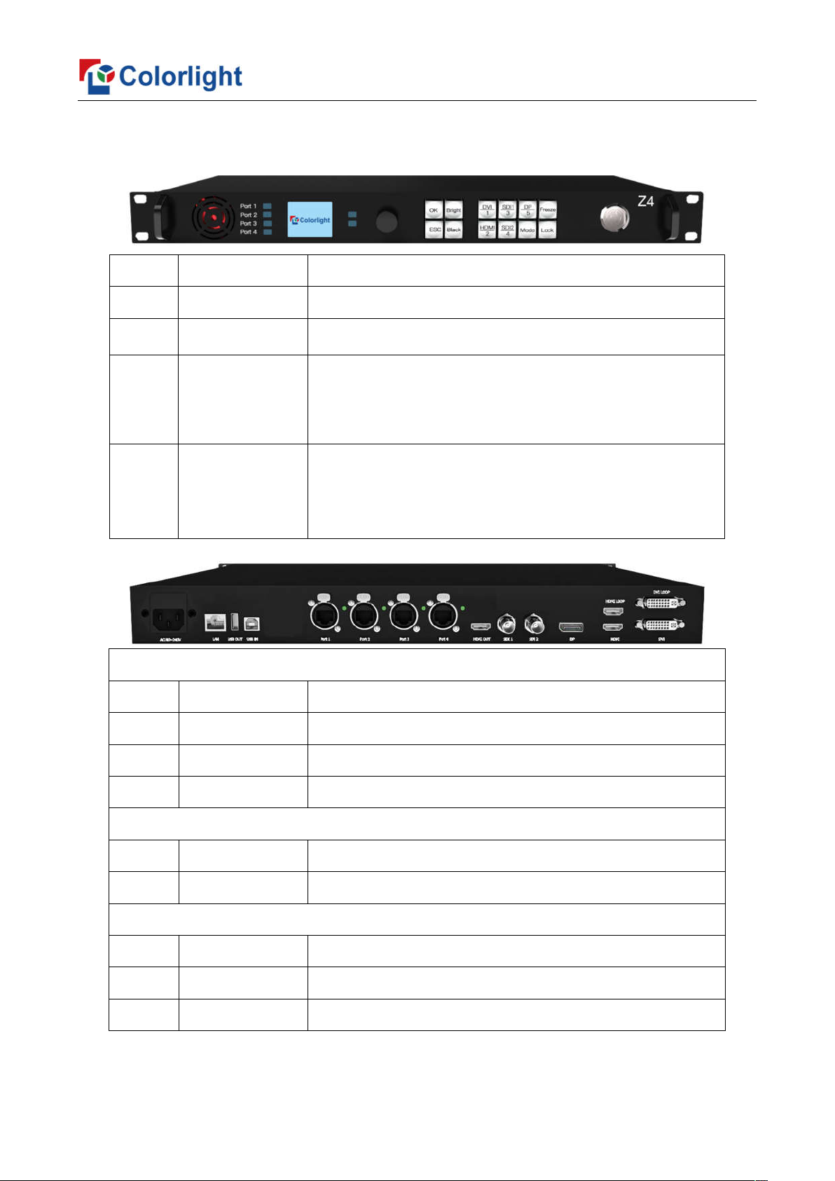
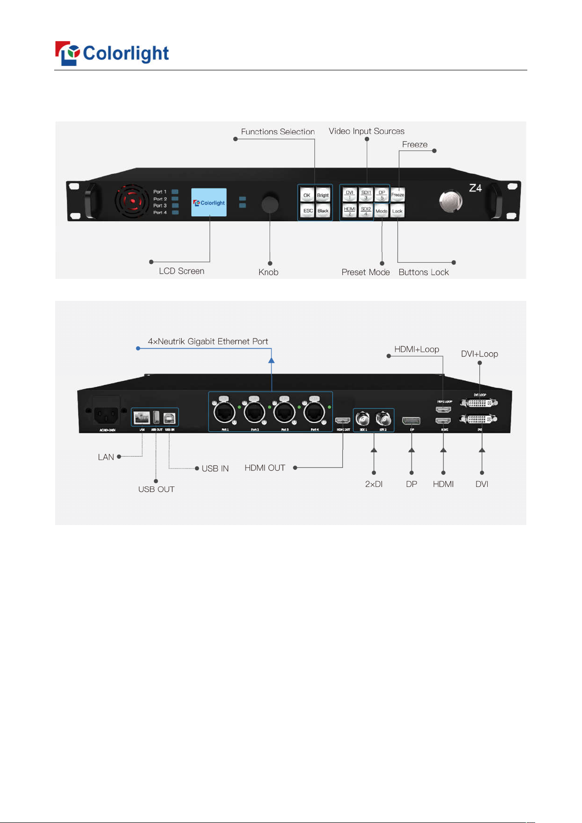
Front Panel
No
. Name Function
1 1.8-in
2 Knob Turning knob to select or adjust
3 Funct
4 Se
Back Panel
Interface
Input
1 HDMI HDMI1.4 input with loop
ch LCD Display operation menu and system information
OK: Enter key
ion keys
lection keys
ESC: Escape current operation or selection
Bright: Brightness option
Black: Blank screen
Mode: Output mode selection of images
Freeze: Freeze screen
Lock: Lock keys
DVI/HDMI/SDI1/SDI2/DP: Set up video source input
2 DV
3 SD
4 DP DP
put Interface
Out
1 Gigabit Ethernet 4 Neutrik Gigabit Ethernet outputs
2 H
olling Interface
Contr
1 100M
2 USB_O
3 USB_IN USB input, connection with PC to configure parameters
I DVI input with loop
I 2x3G-SDI inputs
input
DMI HDMI monitoring output
Ethernet Network Control (communication with PC, or access network)
UT USB output, cascading with next controller
2
Page 5
3 Signal
Connection
3
Page 6
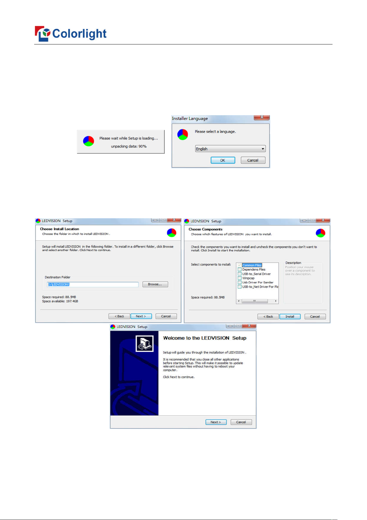
4 LEDVISION Installation
Please download the installation package of the LEDVISION software from
Colorlight’s official website, and complete the installation according to the diagrams shown
below.
1. Run the software package, and select [English] for installer language. Click [OK] to
move on.
2. After selecting a language, an installation wizard like below will appear, click [Next];
Then choose installation location, click [Browse] to change default target location, then
click [Next] after completing;
Choose components according to your own computer status, click [Install] to complete;
After the installation is complete you are ready to use LEDVISION.
4
Page 7
5 Par
LEDVISION to detect sender and all receiving cards.
ameter Configuration
Please make sure the correctness of the hardware connection before setting, use
5.1 Detect Sender and Receiving Card
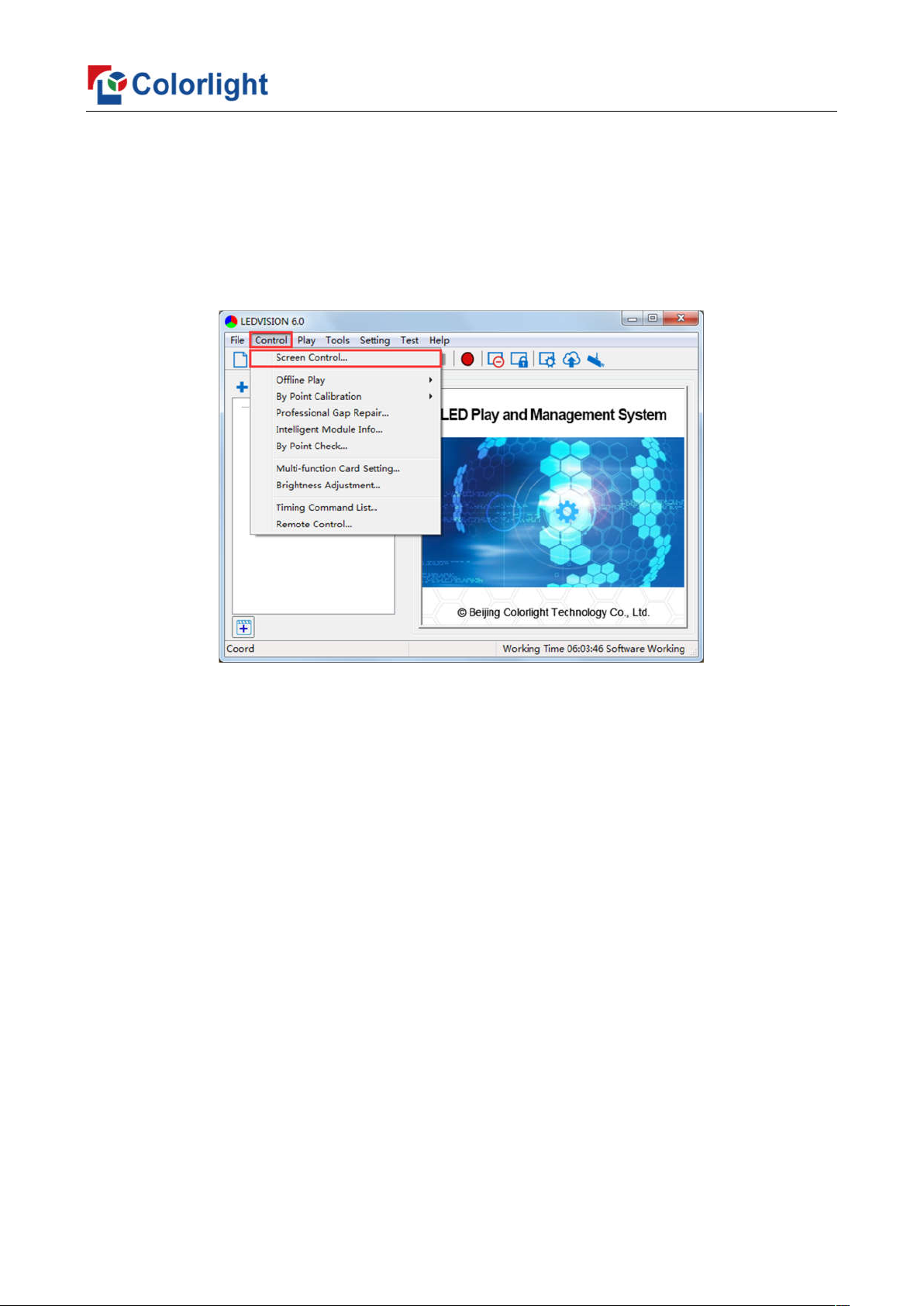
1. Run LEDVISION, click [Control] – [Screen Control] to enter the Screen Control
window.
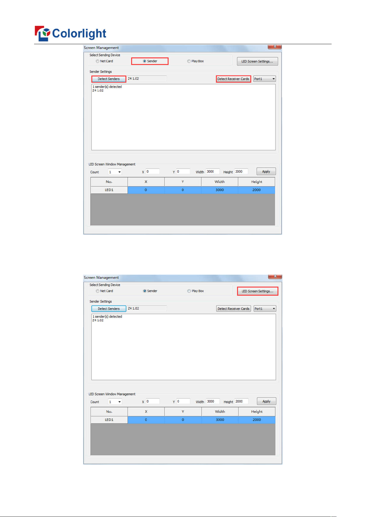
2. [Select Sending Device] for [Sender], click [Detect Senders] in [Sender Settings].
Please check the hardware connection or the installation of relevant driver if cannot detect
senders.
Select network port and click [Detect Receiver Cards] respectively, the software will
automatically acquire the receiver card quantity of each network port of the sender. Please
check corresponding cable if the numbers of receiver card are inconsistent with actual
status.
5
Page 8
5.2 LED Screen Setting
Click [LED Screen Settings] to enter the LED Screen Setting interface, and set up
“Sending Device”, “Screen Parameters”, “Connection Parameters”.
6
Page 9
1 Sending Device Setting
5.2.
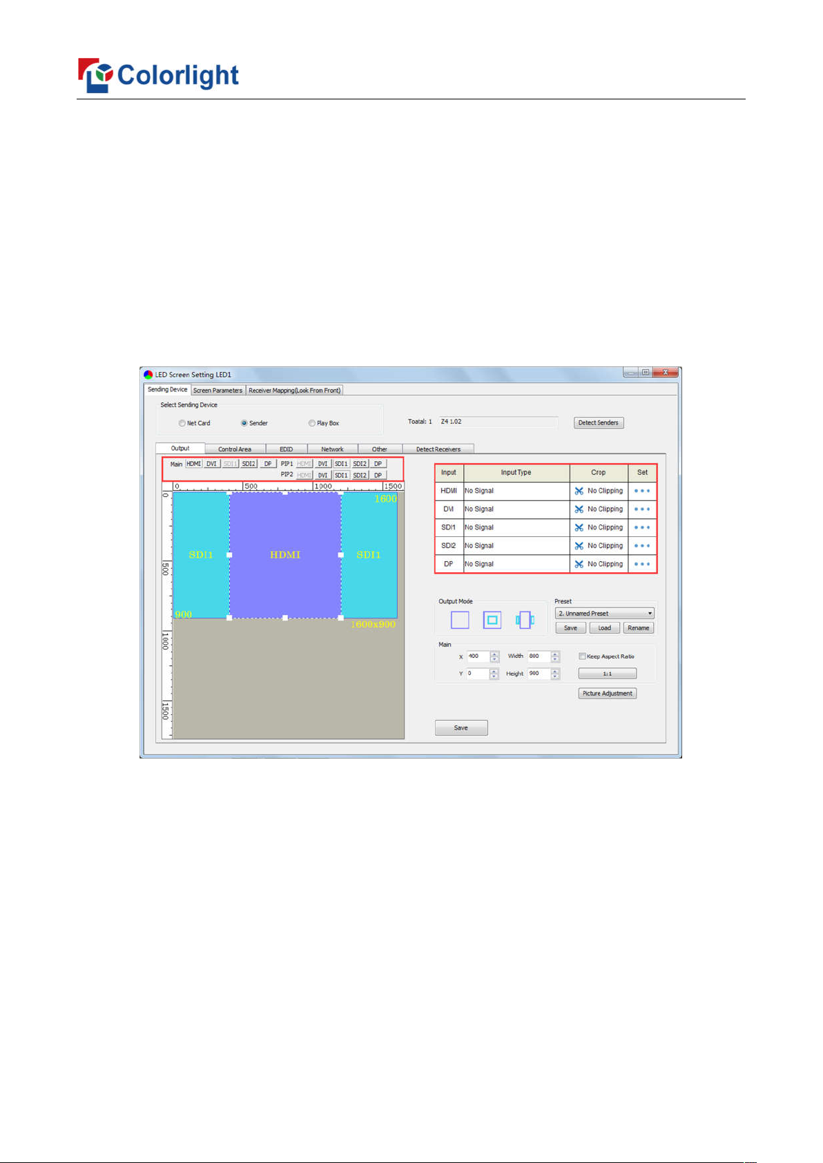
[Select Sending Device] for [Sender], and detect senders. Sending Device Setting
includes 6 parts: Output, Control Area, EDID, Network, Other, Detect Receivers.
1. Output
① Signal Source
When the input signal source of Z4 is normal, the upper right of the software interface will
display the input signal information auto acquired via the software. Users can select specific signal
source (HDMI/DVI/SDI1/SDI2/DP) according to needs in [Main]; If PIP mode has been open, users
can also select specific signal source (HDMI/DVI/SDI1/SDI2/DP) in [PIP]. At the moment, the image
of selected signal source will display in the Image View Area on the left of the software interface.
Note: Main and PIP can’t select the same source. When PIP1 and PIP2 exist in output
mode at the same time, PIP1 and PIP2 can select the same source.
② PIP
There are three output modes of main image and PIP in Output Mode, users can
select specific PIP mode based on the requirement, and conduct the operation like move,
scaling and clipping on the main image and PIP image respectively.
7
Page 10

③ Scaling
In Image View Area, select the image that needs to be scaled, set X, Y, width and
height of it in [Main] or [PIP], or you can click the white box in the bottom right corner of the
image and drag it with the mouse, finally click [Save].
8
Page 11

④ Clipping
Select signal source of the image that needs to be clipped in Input Signal Area, click
[Set] to enter the clipping interface.
In the clipping interface, check [Crop], and set X, Y, width and height in [Cropping
Settings], then click [Save] to complete.
9
Page 12

⑤ Picture Adjustment
Click [Picture Adjustment], enter the interface of picture adjustment. Check [Enable],
and adjust hue, saturation, brightness compensation and contrast ratio of the whole image,
then click [Save] to complete. After setting, you can click [Default Settings] to restore the
default values of every parameter, that is, hue and brightness compensation default to 0,
saturation and contrast ratio default to 100.
⑥ Preset
In [Preset], 16 preset parameters can be saved, and every preset parameter includes
all parameter information of image output (signal source, PIP, scaling, clipping, picture
adjustment), users can directly load one preset parameter to display the image according to
needs, and don’t need to set up all parameters again.
After completing setting up all parameters of image output, select unnamed preset,
click [Save] to save the parameter to sending device; click [Load], send the parameter to
receiving cards. At the time, the image should display on the basis of preset parameter.
10
Page 13

2. In Control Area, it displays the control area of each net port of Z4. Click [Import] and
select correct parameter file, click [Save] to save parameters into corresponding sender; or
set up the control area of each net port respectively (X, Y, Width, Height), click [Save].
3. EDID: Set sender resolution, the first one is the default as current resolution.
11
Page 14

Click the dropdown button to display the resolution list to select the mainstream
resolution, and you can also customize the sender resolution, by setting the width/height
and frame rate.
Click [Save] after setting.
4. Network: Set up IP address, select “Obtain an IP Address Automatically”, then the
sender would auto obtain the IP address; or it would manual set up IP Address, Subnet
Mask and Default Gateway.
12
Page 15

5. Other: Advanced Parameters Setting (Better Graylevel on Low Brightness, Mapping
From Sender, Output Mode, Sender Name), Test Mode Selection, Factory Restore.
6. Detect Receivers: Detect receivers under each net port of Z4 controller, and acquire
relevant information about the receivers (Port, Index, Version, Run Time, Support Chips).
13
Page 16

2 Screen Parameters Setting
5.2.
Observe the display screen with single cabinet as a unit, and if all cabinets themselves
could display normally {it is normal circumstance even the picture between cabinets is not
continuous}, please ignore this step and directly go to the next step.
Otherwise, configuration must be done as follows:
Click [Load], choose the correct parameter file.
Click [Send], to send the loading parameters to the receiving cards. At the moment,
each cabinet should display normally (it is normal circumstance even the picture between
cabinets is not continuous), then click [Save to Receiver] to save the parameters to the
receiving cards.
If each cabinet cannot display normally, you can conduct via the Basic Setting
(Module Information, Box Setting, Performance Setting) or Intelligent Setting, and you
can also contact with the LED screen engineers.
5.2.
3 Connection Parameters Setting
Users don’t need to set up the control area of each net port respectively, but to the
connection relationship between the receiving cards under the network port loading via
each sender, and the software will auto calculate and set up the port control area according
to the connection relationship.
Detailed setting steps as follows:
1. Set up the quantity of receiving card
Set how many receiver (receiving card) that one port manages in Row Count and Col
Count (6*6 as an example) according to the actual loading of LED display, you will see LED
display mapping area from the right side (Viewing from the front of LED display).
14
Page 17

2. Receiving Card Parameters Setting
Select the target sender and the net port from the left side, then select the
corresponding cabinets within net port actual control area and set the connection lines in
the mapping area.
15
Page 18

There are two methods to set up:
①Use mouse to select one by one
In the mapping area, select the first receiving card based on the actual connection of
the net port (view from the front), and then set up the actual loading width and height of the
target receiving card in the right side (128*128 as an example).
Click the receiver (receiving card) one by one, according to actual connecting line, until
the last one for this network port loads.
②Connection Pattern
Aiming at the LED screen with standard connection lines, firstly set up the receiving
card information according to the actual loading width and height (128*128 as an example).
Select the connection line you want from the right side, then cover the corresponding
area of net port loading in mapping area, finally complete setting.
Note: As the cabinets have multiple and different specification (that is the inconsistent
capacity of the receiving card), you can select the different one to adjust separately after
completing setting.
16
Page 19

3. Send & Save to Receiving Card
After setting up all the receiving card parameters and connection lines respectively,
click [Send] to send the correct parameter to the receiving card, and the screen should
display normally at this time.
Then click [Save to Receiver] to save parameters to corresponding receiving card
after confirming.
17
Page 20

6 LCD Oper
ation Instruction
6.1 Operational Motion Instruction
Knob/OK:
Press the knob/OK under main interface to enter operation interface of menu.
Rotate the knob to select menu or press the knob/OK under the operation interface
of menu to select current menu or enter submenu.
Rotate the knob to adjust parameters after selecting the menu with parameter, and
it will be auto saved within one second after adjustment.
ESC: Return key, exit current menu or operation.
6.2 Main Interface
After starting Z4, main interface of LCD display is as follows:
First row: Company name.
Second row: Image resolution.
Third row: Screen brightness, Output mode.
6.3 Operation Instruction
Press the knob/OK to enter the operation interface of main menu, and it includes 12
operation instructions: Display Setting, EDID Setting, Cropping Setting, Output Setting,
Fiber Setting, Preset Setting, Picture Adjust, Output Shift, Tile Mapping, Network Setting,
Language, System Setting.
18
Page 21

1 Display Setting
6.3.
Rotate the knob to select display setting, then press the knob/OK to enter submenu of
“Display Setting”.
1. Brightness: Enter the adjustment interface of “Brightness”, press the knob/OK to turn
on/off the function of broadcast in the option of “Broadcast”, and rotate the knob to change
the percentage of brightness in the option of “Brightness”.
2. CCT: Enter the adjustment interface of “CCT”, rotate the knob to change the value of
color temperature in the option of “CCT”, and you can also press the knob/OK to reset the
value of color temperature as 6500 in the option of “Reset to Default”.
3. Black: Press the knob/OK to switch on/off LED screen.
4. Better Gray: Press the knob/OK to turn on/off the option of “Better Gray”.
5. Test Mode: Enter the setting interface of “Test Mode”, rotate the knob to select test mode,
press ESC back to normal mode.
19
Page 22

6.3.
2 EDID Setting
Rotate the knob to select EDID setting, then press the knob/OK to enter submenu of
“EDID Setting”.
Enter the EDID setting interface of “HDMI” or “DVI” or “DP”. Rotate the knob to select
conventional resolution; or set width, height and frame rate by knob in the option of
“Custom”.
6.3.
3 Cropping Setting
Rotate the knob to select cropping setting, then press the knob/OK to enter submenu
of “Cropping Setting”.
Enter the cropping interface of “HDMI” or “DVI” or “SDI1” or “SDI2” or “DP”, press the
20
Page 23

knob/OK to turn on/off crop. If it has been enabled, set X, Y, width and height of input signal
by knob then save the data.
6.3.
4 Output Setting
Rotate the knob to select output setting, then press the knob/OK to enter submenu of
“Output Setting”; Continue rotating the knob to select “Main” or “PIP1” or “PIP2”, press the
knob/OK to enter the output setting interface. Rotate the knob to adjust X, Y, width and
height of output, then save it.
6.3.
5 Fiber Setting
Rotate the knob to select fiber setting, then press the knob/OK to enter submenu of
“Fiber Setting”. In the submenu, output mode defaults to cable output, users can press the
knob/OK to switch output mode, that is, the output mode is switched to fiber output.
21
Page 24

6 Preset Setting
6.3.
Rotate the knob to select preset setting, then press the knob/OK to enter submenu of
“Preset Setting”.
In the submenu, 16 preset parameters can be saved, and every preset parameter
includes all parameter information of image output (signal source, PIP, scaling, clipping,
picture adjustment), users can also directly load the saved preset parameter to display the
image according to needs, and don’t need to set up all parameters again.
6.3.
7 Picture Adjust
Rotate the knob to select picture adjustment, then press the knob/OK to enter
submenu of “Picture Adjust”. In the submenu, press the knob/OK to turn on/off “Enable”. If
“Enable” has been turned on, users can set hue, saturation, brightness and contrast of
image by knob then save the data; and users can also restore the default values of every
parameter, that is, hue and brightness default to 0, saturation and contrast default to 100.
22
Page 25

8 Output Shift
6.3.
Rotate the knob to select output shift, then press the knob/OK to enter submenu of
“Output Shift”.
Output shift includes two ways: “Whole” and “By Port”. In the setting interface of
“Whole”, you can rotate the knob to set X and Y of the whole image and save it; in the
setting interface of “By Port”, you can set X and Y of the image of each net port respectively,
then save it.
6.3.
9 Tile Mapping
Rotate the knob to select tile mapping, then press the knob/OK to enter submenu of
“Tile Mapping”. In the submenu, press the knob/OK to set sender as the connection source.
At this time, rotate the knob and press the knob/OK to enter the setting interface, select the
net port of which need to be set and set offset values of X and Y, also, you can set the width,
height, row, column and link type of corresponding cabinets, then save all the parameters.
6.3.10 Others
Network Setting: Users can automatically obtain an IP address or set manually. Enter
the setting interface of “Network Setting”, press the knob/OK to turn on/off DHCP; or press
the knob/OK to enter manual IP setting, you can set up IP, subnet and gateway respectively
23
Page 26

via the knob.
Language: Enter the setting interface of “Language”, press the knob/OK to switch the
language.
System Setting: In “System Setting”, users can set date and time, restore factory
settings and check current firmware information.
24
Page 27

 Loading...