


 Loading...
SEARCHLIGHT SYSTEM
BY COLORLIGHT
INSTALLATION MANUAL
Revision nr: F1.3 Revision date: 2014-05

Safety reminder
Remember to break all electrical power to system before starting any work in the electrical box or the searchlight unit.
All information in this manual was correct at time of publication. However, as our engineers are always updating and improving our products, your system's software might provide a slightly different appearance or modified functionality than presented in this manual.
If your system lacks any function presented in this manual, there is possibly a software update available to resolve this, please contact ColorLight for more information.
COPYRIGHT COLORLIGHT © 2014. All rights reserved
Page 2 |
INSTALLATION MANUAL CL20 |

CONTENT
1. |
WARNINGS AND INFORMATION ..................................................................................... |
5 |
||
2. |
WARRANTY CONDITIONS................................................................................................ |
7 |
||
3. |
MAINTENANCE AND SERVICE PLAN.............................................................................. |
8 |
||
4. |
COLORLIGHT SEARCHLIGHT SYSTEM .......................................................................... |
9 |
||
5. |
INSTALLATION................................................................................................................. |
10 |
||
|
5.1 |
Physical handling of the searchlight ....................................................................... |
10 |
|
6. |
CLI-30001, ANTI VIBRATION KIT..................................................................................... |
11 |
||
7. |
CLI-30005, REPLACING THE BULB ................................................................................ |
14 |
||
8. |
ELECTRICAL SYSTEM..................................................................................................... |
20 |
||
|
8.1 |
Electrical-box (115/230VAC)..................................................................................... |
20 |
|
|
8.2 |
Cabinet card .............................................................................................................. |
21 |
|
|
8.3 |
Electrical-box overview (115/230VAC)..................................................................... |
22 |
|
|
8.4 |
Electrical-box overview (24VDC) ............................................................................. |
23 |
|
|
8.5 |
Electrical box installation......................................................................................... |
24 |
|
|
8.6 |
Operator panel connections..................................................................................... |
25 |
|
|
8.7 |
Ethernet wiring.......................................................................................................... |
26 |
|
9. |
OPERATOR PANEL, OVERVIEW..................................................................................... |
27 |
||
10. DISPLAY SYMBOLS AND MESSAGES........................................................................ |
28 |
|||
|
10.1 |
Ebox alarm relay ....................................................................................................... |
29 |
|
11. ACTIONS AFTER INSTALLATION OR POWER FAILURE........................................... |
30 |
|||
12. |
STARTING SYSTEM ..................................................................................................... |
31 |
||
13. |
JOYSTICK FUNCTIONS................................................................................................ |
32 |
||
14. |
SWITCH ON LIGHT ....................................................................................................... |
33 |
||
15. |
FOCUS........................................................................................................................... |
34 |
||
|
15.1 |
Type 1, continuous focus (standard)....................................................................... |
34 |
|
16. CABINET CARD MENU SYSTEM ................................................................................. |
35 |
|||
|
16.1 |
Menu navigation........................................................................................................ |
35 |
|
|
16.1.1 |
Down Button........................................................................................................................ |
35 |
|
|
16.1.2 |
Right Button......................................................................................................................... |
35 |
|
|
16.1.3 |
OK Button............................................................................................................................ |
35 |
|
|
16.2 |
Category 1: About..................................................................................................... |
36 |
|
|
16.2.1 |
(1.1) MAC Address.............................................................................................................. |
36 |
|
|
16.2.2 |
(1.2) IP Address .................................................................................................................. |
36 |
|
|
16.2.3 |
(1.3) Light Model ................................................................................................................. |
36 |
|
|
16.2.4 |
(1.4) SW Version ................................................................................................................. |
36 |
|
|
16.3 |
Category 2: Diagnostics (support tool) ................................................................... |
37 |
|
|
16.3.1 |
(2.1) Start ............................................................................................................................ |
37 |
|
|
16.3.2 |
(2.2) View Results ............................................................................................................... |
37 |
|
INSTALLATION MANUAL CL20 |
Page 3 |

16.4 |
Category 3: Usage Stats........................................................................................... |
38 |
||
16.4.1 |
(3.1) |
Left Light ..................................................................................................................... |
38 |
|
16.4.2 |
(3.2) |
Right Light................................................................................................................... |
38 |
|
16.4.3 |
(3.3) |
Reset Left.................................................................................................................... |
38 |
|
16.4.4 |
(3.4) |
Reset Right ................................................................................................................. |
38 |
|
16.5 |
Category 4: Settings ................................................................................................. |
39 |
||
16.5.1 |
(4.1) |
OP WDT...................................................................................................................... |
39 |
|
16.5.2 |
(4.2) |
OP WDT Stats ............................................................................................................ |
40 |
|
16.5.3 |
(4.3) |
OP WDT Reset ........................................................................................................... |
40 |
|
17. |
TECHNICAL DATA CL20 .............................................................................................. |
41 |
||
17.1 |
Specifications CL20.................................................................................................. |
41 |
||
17.2 |
Mechanical drawings................................................................................................ |
42 |
||
17.2.1 |
Operator Panel .................................................................................................................... |
42 |
||
17.2.2 Electrical box CL20, 115/230VAC....................................................................................... |
43 |
|||
17.2.3 Electrical box CL20, 24VDC................................................................................................ |
44 |
|||
17.2.4 |
Searchlight CL20................................................................................................................. |
45 |
||
18. |
SUPPORT |
...................................................................................................................... |
46 |
|
Approvals
written by: |
reviewed by: |
approved by: |
Anders Holst |
Jonas Boslander |
Mattias Svensson |
Page 4 |
INSTALLATION MANUAL CL20 |
1.WARNINGS AND INFORMATION
High voltage!
Before opening any part of the searchlight system, make sure all power is switched off!
Halogen bulbs
Make sure the bulb is properly installed into socket to obtain good electrical contact and to avoid damaging bulb and/or socket.
To avoid damage to bulb, do not twist. Pull old lamp straight out and push new bulb straight in.
Never bump, drop, apply excessive stress, or scratch the bulb. This could cause the bulb to burst! Do not operate any bulbs with any traces of scratches, cracks, or physical damage
Always transport the bulb in the provided protective case or cover until installation! Save the protective case or cover and packaging materials (box) for bulbs that have been used to their rated service life. Use the protective case when disposing of the bulbs.
Always use safety glasses when installing or removing the bulbs.
When changing bulbs be sure to not touch the surface of the bulbs with bare fingers. If inadvertently touched with bare fingers it should be degreased immediately with alcohol and a soft lint free cloth. Be sure to wipe dry the bulb surface afterwards.
Never touch the bulb when it is on, or soon after it has been turned off, as it is hot and will cause serious burns. Bulbs should be allowed to cool for a minimum of ten (10) minutes after the light is turned off.
The light should never under any circumstances be turned on without frontglass.
Reflectors
The parabolic reflectors developed by ColorLight have an extremely smooth surface to focus the light in wide or narrow beam. Bare fingers should never touch the reflector surface. If inadvertently touched, the reflector surface should immediately be degreased with alcohol and a soft lint free cloth.
INSTALLATION MANUAL CL20 |
Page 5 |
Light beam heat damage and Ethernet communications guard OP WDT
This searchlight is built for use on long distances and the high-intensity light from the searchlight can, if set at a narrow beam, cause severe damage to surfaces closer than 1 meter. To avoid that the searchlight is forgotten with the light on, always use the feature “off and park” when not using the searchlight.
If however a hardware failure occurs that breaks the Ethernet communication between the box and operator panel, a safety function will step in and automatically turn off the light within 3 seconds, the OP WDT will also interrupt an ongoing sweep or surveillance activity.
OP WDT is disabled by default, to enable see 16.5.1 (4.1) OP WDT.
If protection hoods are used over searchlight body the system main power switch in the electric box should be off; this is a precaution to reduce the risk of fire if the hoods are not removed before turning the lights on.
Cleaning
Never wash the searchlight with water under high pressure because this can penetrate through the seals and cause damage to mechanical and electrical components.
Do not use strong solvents such as thinner or acetone to clean the searchlight body or the operator panel.
Deicing
Removal of ice should be done with caution. Physical violence can damage the front glass or the searchlight driving mechanics. Instead turn on the lights and let the heat melt the ice.
Recycling and disposal
Disposal of spent lamps must be in accordance with local and national regulations.
Page 6 |
INSTALLATION MANUAL CL20 |

2.WARRANTY CONDITIONS
A correctly installed searchlight system from ColorLight requires no planned regular maintenance or service during the first 10 years in operation (except changing the bulbs after they are used up).
The “Maintenance and Service plan” describes how to keep the product in good condition.
The warranty is conditioned by below mentioned key points.
Before powering up the unit, make sure that:
Vibration dampers are mounted correctly according to installation manual.
The mechanical fundament where the searchlight is placed is robust.
Warranty seal on the service hatch is unbroken.
Outgoing cable radius from the searchlight is smooth and not stressed.
All cables used for the installations are as per ColorLight’s specifications or as per separate made agreement.
Signal cables are not placed together with high power cables.
Electrical connections are made according to electrical scheme and wiring diagram.
Length of cables are not exceeding the recommended maximum lengths as stated below:
Power/signal cables between searchlight and E-box for 230 VAC-system: Max 30 meter
Power cables between searchlight and E-box for 24 VDC-system: Max 5 meter
Remote cable / Ethernet cable between E-box and remote control: Max 100 meter (longer distance requires an amplifier or fibre optic version).
E-box (EB) is placed in an non-condense environment with a minimum temperature of +5 C (indoor) if not customised for other installation.
The remote panel (OP) is bridge mounted in an IP54 environment. If placed outside it must be under a protection hood when not in use.
Remote panel is screwed in bridge panel, properly grounded and correct installed.
After above checkpoints are verified the system should be started up as per User’s
Manual to verify the functionalities.
In case of any questions related to the warranty, please contact us at info@colorlight.com for additional support.
INSTALLATION MANUAL CL20 |
Page 7 |

3.MAINTENANCE AND SERVICE PLAN
Although the system does not require regular maintenance to function, we recommend, however, that this preventive maintenance plan is followed in order to keep the searchlight in good condition and in time detect if something is wrong and needs to be corrected.
Recommended inspection on a weekly basis
1.Make visual inspection of the searchlight housing and cabling. Look for any potential mechanical damage caused by external force. A damage can lead to reduced or nonfunctionality.
2.Make a visual inspection of the searchlight glasses. Verify that they are without any crack or broken in any way. A crack can lead to water penetration inside the housing followed by potential electrical and mechanical problem.
3.Perform a function test. Start up the searchlight system, rotate the searchlight in horizontal and vertical direction. Check the “lamp life” statistics in order to plan any potential replacement of bulb. The system is programmed to give a warning when there is less than 130h of lamp bulb lifetime remaining.
4.Clean the searchlight. Rinse with fresh water to wash away the salt deposits. If more dirty, use a very soft sponge and soap that is not caustic, contains strong solvents such as acetone or thinner base. The house can be both polished and waxed for a shiny and durable surface, but the glass should under no circumstances be waxed. Under no circumstances can the searchlights be washed with high pressure water as this can lead to penetration inside the housing followed by potential electrical and mechanical problem.
5.Deicing. Winter time the system should be deiced with caution. First turn the lights on to let the heat melt the ice before operating the system horizontally and vertically.
Page 8 |
INSTALLATION MANUAL CL20 |
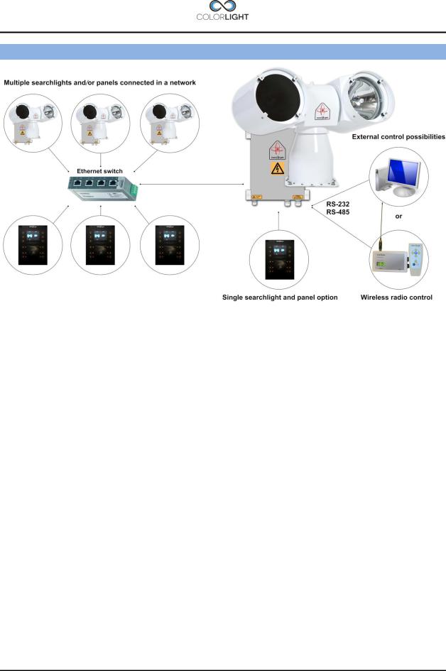
4.COLORLIGHT SEARCHLIGHT SYSTEM
ColorLight has with its newly developed control system for searchlights opened for a flexible and future-proof system in which several searchlight assemblies (CL20, CL25 and CL35) and operator panels can be connected to a dedicated network and communicate via the Ethernet infrastructure.
Control-computers and navigation equipment are other examples of devices that can be part of this network.
For external communication between the electrical box and its various controllers we use the TCP/IP protocol through the Ethernet infrastructure, but for internal communication between the box and searchlight we have chosen to work with CAN bus technology.
CAN (Controller Area Network) is a network standard originally developed for the automotive industry and with only two wires it’s possible to transmit a variety of control data and information.
The searchlights drive motors (horizontal and vertical) are of the type brushless servo motors, with excellent performance, long lifetime and high reliability.
The motor drivers are located inside the searchlight and are of an "intelligent" type, which constantly analyzes the motor condition, and if problems arise, such as tripped over current protection; this will be presented as an alarm in the operator panel.
INSTALLATION MANUAL CL20 |
Page 9 |
5.INSTALLATION
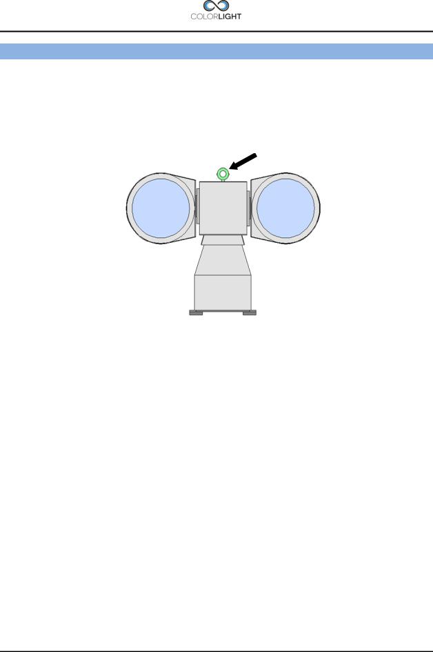
5.1Physical handling of the searchlight
Lift only the searchlight by the temporary lift loop on top of the center house. Lifting at the lamp houses may damage the construction. After safely fixed the searchlight, remove the lift loop.
Lift here!
Page 10 |
INSTALLATION MANUAL CL20 |
6.CLI-30001, ANTI VIBRATION KIT
Service instruction no: CLI-30001
Revision date: 2012-12-19
Applicable models: CL20-11, CL25-**, CL35-**
Spareparts needed (refer to CL spareparts list)
1 CLS-25130 Anti vibration-kit × 1 (included in delivery)
2
Tools and supplies required:
117mm ratchet wrench × 1
217mm wrench × 1
3
4
Important information
This instruction shows how to install the anti-vibration kit which consists of four dampers with integrated stainless steel tubes.
The dampers main function is to absorb the harmful vibrations that can damage the mechanics and shorten the life of the bulbs. Searchlight installations without dampers will uncompromisingly, void the warranty.
Figure 1
1.Overview of the damper assembly and its parts.
INSTALLATION MANUAL CL20 |
Page 11 |

2.Push the dampers tube part thru the mounting holes in the foundation.
3.Mount the dampers rubber part from other side of the foundation.
4.Lower the searchlight on top of dampers and mount bolt washers and nuts as shown in figure 1.
Page 12 |
INSTALLATION MANUAL CL20 |

5.The lock nut is tightened with two wrenches size 17mm, tighten nut firmly.
The dampers rubber part will be compressed slightly, after assembly the searchlight will be rigidly secured but still resistant to vibrations.
INSTALLATION MANUAL CL20 |
Page 13 |
7.CLI-30005, REPLACING THE BULB
Service instruction no: CLI-30005
Revision date: 2013-09-09
Applicable models: CL20-11, CL25-**, CL35-**
Spareparts needed (refer to CL spareparts list)
CL20-11
1CLN0093 (Halogen bulb 250W) × 1
2CLS-25330 Front glass sealing × 1
CL25-**
1CLN0166 (HMI / UV bulb 400W) × 1
2CLS-25330 Front glass sealing × 1
CL35-**
1CLN0094 (HMI / UV bulb 575W) × 1
2CLS-35318 Front glass sealing × 1
Tools and supplies required:
18mm Ratchet Wrench × 1
2Suction cup tool × 1
3Lint-free cloth
4Isopropyl (rubbing) alcohol
Important information
This instruction shows how to replace the bulb and front glass sealing on the CL25 model equipped with white or UV light but the procedure is the same for CL20 and CL35.
It’s recommended to replace the front glass sealing when replacing the bulb, reflector or front glass to reduce the risk of water ingress between front glass and lamp housing.
Regarding safe handling of bulbs please read: Warnings and Information, page 5
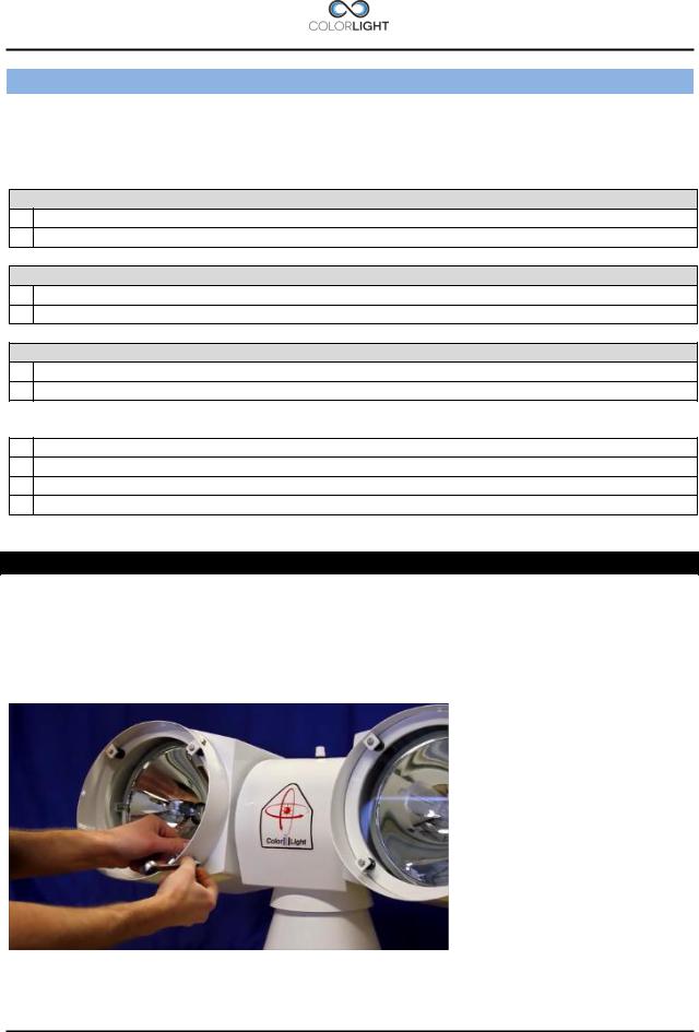
1.Turn off system power before servicing.
2.Start by removing all the four glass holder brackets that keeps the glass in place. Use a ratchet wrench size 8mm.
Page 14 |
INSTALLATION MANUAL CL20 |
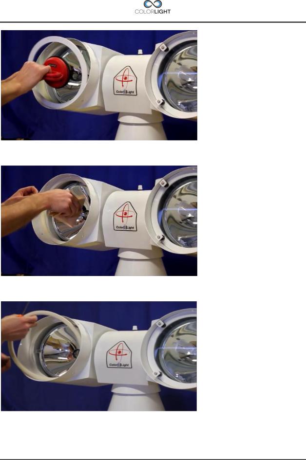
3.Remove the front glass; this is best done with a suction cup tool.
4.Remove the defective bulb from the socket.
5.Remove the old sealing.
Make sure that the flange surface is clean.
INSTALLATION MANUAL CL20 |
Page 15 |
Loading...