

Page 1
SEARCHLIGHT SYSTEM
CLITE2
CLITE2IR
24VDC
100-240VAC
50/60 Hz
BY COLORLIGHT
INSTALLATION & USER'S MANUAL
Revision nr: F1.11
Revision date: 2016-05-13
Page 2

Safety reminder
Remember to break all electrical power to system before
starting any work in the electrical box or the searchlight
unit.
All information in this manual was correct at time of publication. However, as our engineers are
always updating and improving our products, your system's software might provide a slightly
different appearance or modified functionality than presented in this manual.
If your system lacks any function presented in this manual, there is possibly a software update
available to resolve this, please contact Colorlight for more information.
COPYRIGHT COLORLIGHT © 2016. All rights reserved
Page 2 INSTALLATION & USER'S MANUAL CLITE2
Page 3

CONTENT
WARNINGS AND INFORMATION ...................................................................................... 6 1.
WARRANTY CONDITIONS CLITE2 ................................................................................... 7 2.
MAINTENANCE AND SERVICE PLAN .............................................................................. 8 3.
COLORLIGHT SEARCHLIGHT SYSTEM........................................................................... 9 4.
OPERATOR PANEL, OVERVIEW .................................................................................... 10 5.
DISPLAY SYMBOLS AND MESSAGES .......................................................................... 11 6.
Ebox alarm relay ...................................................................................................... 12 6.1
installation ....................................................................................................................... 13 7.
Lifting the searchlight ............................................................................................. 13 7.1
CLI-30001, ANTI VIBRATION KIT .................................................................................... 14 8.
Electrical system ............................................................................................................. 17 9.
Electrical box mounting position ........................................................................... 17 9.1
Electrical box installation........................................................................................ 18 9.2
Cabinet card ............................................................................................................. 19 9.3
CLITE2 electrical-box overview (24VDC) ............................................................... 20 9.4
9.4.1 CLITE2 electrical-box connection (24VDC) .......................................................................... 21
CLITE2 electrical-box overview (100-240VAC) ...................................................... 22 9.5
9.5.1 CLITE2 electrical-box connection (100-240VAC) ................................................................. 23
Operator panel connections ................................................................................... 24 9.6
Ethernet wiring ........................................................................................................ 25 9.7
ACTIONS AFTER INSTALLATION and POWER FAILURE ......................................... 26 10.
Automatic recovery of stored searchlight position in panel. ............................... 26 10.1
10.1.1 The panel position indicator differs from the actual position of the searchlight. ............... 26
Synchronize the system .......................................................................................... 27 10.2
STARTING SYSTEM .................................................................................................... 28
11.
JOYSTICK FUNCTIONS ............................................................................................... 29 12.
SWITCH ON LIGHT ...................................................................................................... 30 13.
QUICK START MENU .................................................................................................. 31 14.
Fixed positions (optional function) ........................................................................ 31 14.1
14.1.1 Go to fixed position ........................................................................................................... 31
14.1.2 Store fixed position............................................................................................................ 32
Sweep (optional function) ....................................................................................... 33 14.2
14.2.1 New Sweep ....................................................................................................................... 33
14.2.2 Modify sweep parameters ................................................................................................. 34
Surveillance (optional function) ............................................................................. 36
14.3
14.3.1 Setting a new surveillance sweep ..................................................................................... 36
14.3.2 Changing surveillance settings ......................................................................................... 38
INSTALLATION & USER'S MANUAL CLITE2 Page 3
Page 4

Switch ....................................................................................................................... 40 14.4
Synchronized control .............................................................................................. 41 14.5
14.5.1 Set the master control searchlight on/off .......................................................................... 43
14.5.2 Add and remove slaves .................................................................................................... 44
Off and park ............................................................................................................. 45 14.6
MAIN MENU.................................................................................................................. 46 15.
Off and Park ................................................................................................ ............. 46 15.1
Switch system .......................................................................................................... 46 15.2
Light Position ........................................................................................................... 46 15.3
Sweep ....................................................................................................................... 46 15.4
Surveillance ............................................................................................................. 46 15.5
Info ............................................................................................................................ 47 15.6
Status ....................................................................................................................... 47 15.7
Settings .................................................................................................................... 48 15.8
15.8.1 Backlight brightness (adjust the button´s/ display light intensity) ..................................... 48
15.8.2 Language .......................................................................................................................... 48
15.8.3 Joystick direction ............................................................................................................... 49
15.8.4 Maximum rotation speed ................................................................................................... 50
15.8.5 Installation ......................................................................................................................... 51
15.8.5.1 Store origin ............................................................................................................................... 51
15.8.5.2 Store park position................................................................................................................... 52
15.8.5.3 Name system ........................................................................................................................... 53
15.8.5.4 Start test sequence ................................................................................................................. 54
15.8.5.5 Single lamp mode .................................................................................................................... 55
15.8.5.6 OP Rotation .............................................................................................................................. 56
15.8.5.7 Options setup ........................................................................................................................... 58
CABINET CARD MENU SYSTEM ................................................................................ 59 16.
Menu navigation ...................................................................................................... 59 16.1
16.1.1 Down Button ...................................................................................................................... 59
16.1.2 Right Button ...................................................................................................................... 59
16.1.3 OK Button .......................................................................................................................... 59
Category 1: About ................................................................................................... 60
16.2
16.2.1 (1.1) MAC Address............................................................................................................ 60
16.2.2 (1.2) IP Address ................................................................................................................ 60
16.2.3 (1.3) Light Model ............................................................................................................... 60
16.2.4 (1.4) SW Version ............................................................................................................... 60
Category 2: Diagnostics (support tool) .................................................................. 61 16.3
16.3.1 (2.1) Start .......................................................................................................................... 61
16.3.2 (2.2) View Results ............................................................................................................. 61
Category 3: Usage Stats ......................................................................................... 62 16.4
16.4.1 (3.1) Left Light ................................................................................................................... 62
16.4.2 (3.2) Right Light ................................................................................................................. 62
16.4.3 (3.3) Reset Left ................................................................................................................. 62
16.4.4 (3.4) Reset Right ............................................................................................................... 62
Page 4 INSTALLATION & USER'S MANUAL CLITE2
Page 5

Approvals
written by:
Anders Holst
reviewed by:
Jonas Boslander
approved by:
Mattias Svensson
Category 4: Settings ................................................................................................ 63 16.5
16.5.1 (4.1) OP WDT ................................................................................................................... 63
16.5.2 (4.2) OP WDT Stats .......................................................................................................... 64
16.5.3 (4.3) OP WDT Reset ......................................................................................................... 64
Technical DATA ........................................................................................................... 65 17.
Specifications CLITE2 ............................................................................................. 65 17.1
Mechanical drawings ............................................................................................... 66 17.2
17.2.1 Operator Panel .................................................................................................................. 66
17.2.2 Electrical box CLITE2, 100-240VAC ................................................................................. 67
17.2.3 Electrical box CLITE2, 24VDC .......................................................................................... 68
17.2.4 Searchlight CLITE2 (standard) ......................................................................................... 69
17.2.5 Searchlight CLITE2 IR (with camera) ............................................................................... 70
CLITE2 Searchligt with Thermal Camera ................................................................... 71 18.
Introduction ............................................................................................................. 71 18.1
Specifications .......................................................................................................... 72 18.2
CLITE2ir - video connection ....................................................................................... 74 19.
Set cam video standard .............................................................................................. 75 20.
Menu navigation ...................................................................................................... 75 20.1
20.1.1 Down Button ...................................................................................................................... 75
20.1.2 Right Button ...................................................................................................................... 75
20.1.3 OK Button .......................................................................................................................... 75
Factory setup, how to change between PAL and NTSC. ...................................... 76 20.2
USING THE THERMAL CAMERA IN CAM MODE ....................................................... 77 21.
Activate the thermal camera ................................................................................... 77 21.1
Camera tilt ................................................................................................................ 79 21.2
21.2.1 Tilt up ................................................................................................................................ 79
21.2.2 Tilt down ............................................................................................................................ 80
Spot meter ................................................................................................................ 81 21.3
Menu - CAM settings ................................................................................................... 82 22.
Palette ...................................................................................................................... 83 22.1
Zoom ........................................................................................................................ 84 22.2
SUPPORT ..................................................................................................................... 85 23.
INSTALLATION & USER'S MANUAL CLITE2 Page 5
Page 6
WARNINGS AND INFORMATION 1.
CAUTION!
Before servicing any part of the searchlight system, make sure all power is
switched off!
Cleaning
Never wash the searchlight with water under high pressure because this can
penetrate through the seals and cause damage to mechanical and electrical
components.
Do not use strong solvents such as thinner or acetone to clean the searchlight
body or the operator panel.
Deicing
Removal of ice should be done with caution. Physical violence can damage the
LED-lamp modules or the searchlight driving mechanics.
LED-modules developed by LUMINELL AS
The LED-modules we use are developed by Luminell AS in Norway for Colorlight.
The CLITE LED-housing has a sealed, solid and compact construction with
powerful light distribution and excellent thermal design.
The high quality CLITE Led module is designed and manufactured in Scandinavia.
For more information, please visit:
www.luminell.com/
Page 6 INSTALLATION & USER'S MANUAL CLITE2
Page 7

WARRANTY CONDITIONS CLITE2 2.
A correctly installed searchlight system from Colorlight requires no planned regular maintenance
or service during the first 10 years in operation.
The “Maintenance and Service plan” describes how to keep the product in good condition.
The warranty is conditioned by below mentioned key points.
Before powering up the unit, make sure that:
Vibration dampers are mounted correctly according to this installation manual.
The mechanical fundament where the searchlight is placed is robust.
Warranty seal on the service hatch is unbroken.
Outgoing cable radius from the searchlight is smooth and not stressed.
All cables used for the installations are as per Colorlight’s specifications or as per
separate made agreement.
Signal cables are not placed together with high power cables.
Electrical connections are made according to electrical scheme and wiring diagram.
Length of cables are not exceeding the recommended maximum lengths as stated
below:
Power/signal cables between searchlight and E-box for 100-240VAC-system: Max
30 meter
Power cables between searchlight and E-box for 24 VDC-system: Max 7 meter
Remote cable / Ethernet cable between E-box and remote control: Max 100 meter
(longer distance requires an amplifier or fibre optic version).
E-box (EB) is placed in an non-condense environment with a minimum temperature of
+5 C (indoor) if not customised for other installation.
The remote panel (OP) is bridge mounted in an IP56 environment. If placed outside it
must be under a protection hood when not in use.
Remote panel is screwed in bridge panel, properly grounded and correct installed.
After above checkpoints are verified the system should be started up as per this manual
to verify the functionalities.
In case of any questions related to the warranty, please contact us at info@colorlight.com for
additional support.
INSTALLATION & USER'S MANUAL CLITE2 Page 7
Page 8

MAINTENANCE AND SERVICE PLAN 3.
Although the system does not require regular maintenance to function, we recommend,
however, that this preventive maintenance plan is followed in order to keep the searchlight in
good condition and in time detect if something is wrong and needs to be corrected.
Recommended inspection on a weekly basis
1. Make visual inspection of the searchlight housing and cabling. Look for any potential
mechanical damage caused by external force. A damage can lead to reduced or nonfunctionality.
2. Make a visual inspection of the searchlight glasses. Verify that they are without any
crack or broken in any way. A crack can lead to water penetration inside the housing
followed by potential electrical and mechanical problem.
3. Perform a function test. Start up the searchlight system, rotate the searchlight in
horizontal and vertical direction.
4. Clean the searchlight. Rinse with fresh water to wash away the salt deposits. If more
dirty, use a very soft sponge and soap that is not caustic, contains strong solvents such
as acetone or thinner base. The house can be both polished and waxed for a shiny and
durable surface, but the glass should under no circumstances be waxed. Under no
circumstances can the searchlights be washed with high pressure water as this can lead
to penetration inside the housing followed by potential electrical and/or mechanical
problem.
5. Deicing. Winter time the system should be deiced with caution. First turn the lights on to
let the heat melt the ice before operating the system horizontally and vertically.
Page 8 INSTALLATION & USER'S MANUAL CLITE2
Page 9
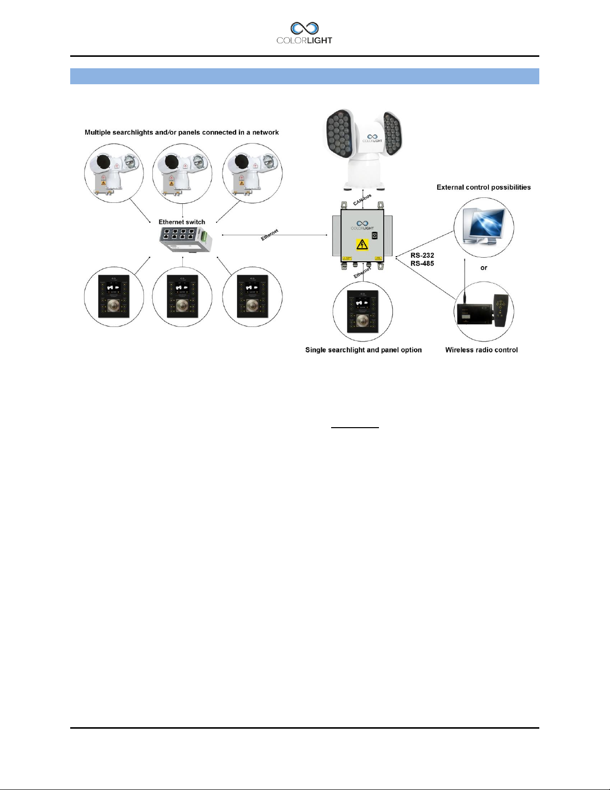
COLORLIGHT SEARCHLIGHT SYSTEM 4.
Colorlight has with its newly developed control system for searchlights opened for a flexible and
future-proof system in which several searchlight assemblies (CLITE2, CLED, CL20, CL25 and
CL35/38) and operator panels can be connected to a dedicated network and communicate via
the Ethernet infrastructure.
Control-computers and navigation equipment are other examples of devices that can be part of
this network.
For external communication between the electrical box and its various controllers we use the
TCP / IP protocol through the Ethernet infrastructure.
For internal communication between the box and searchlight we have chosen to work with CAN
bus technology. CAN (Controller Area Network) is a network standard originally developed for
the automotive industry and with only two wires it’s possible to transmit a variety of control data
and information.
The searchlights drive motors (horizontal and vertical) are of the type brushless servo motors,
with excellent performance, long lifetime and high reliability.
The motor drivers are located inside the searchlight and are of an "intelligent" type, which
constantly analyzes the motor condition, and if problems arise, such as tripped over current
protection; this will be presented as an alarm in the operator panel.
INSTALLATION & USER'S MANUAL CLITE2 Page 9
Page 10
8
6
5 9 2
3
1
7
4
1
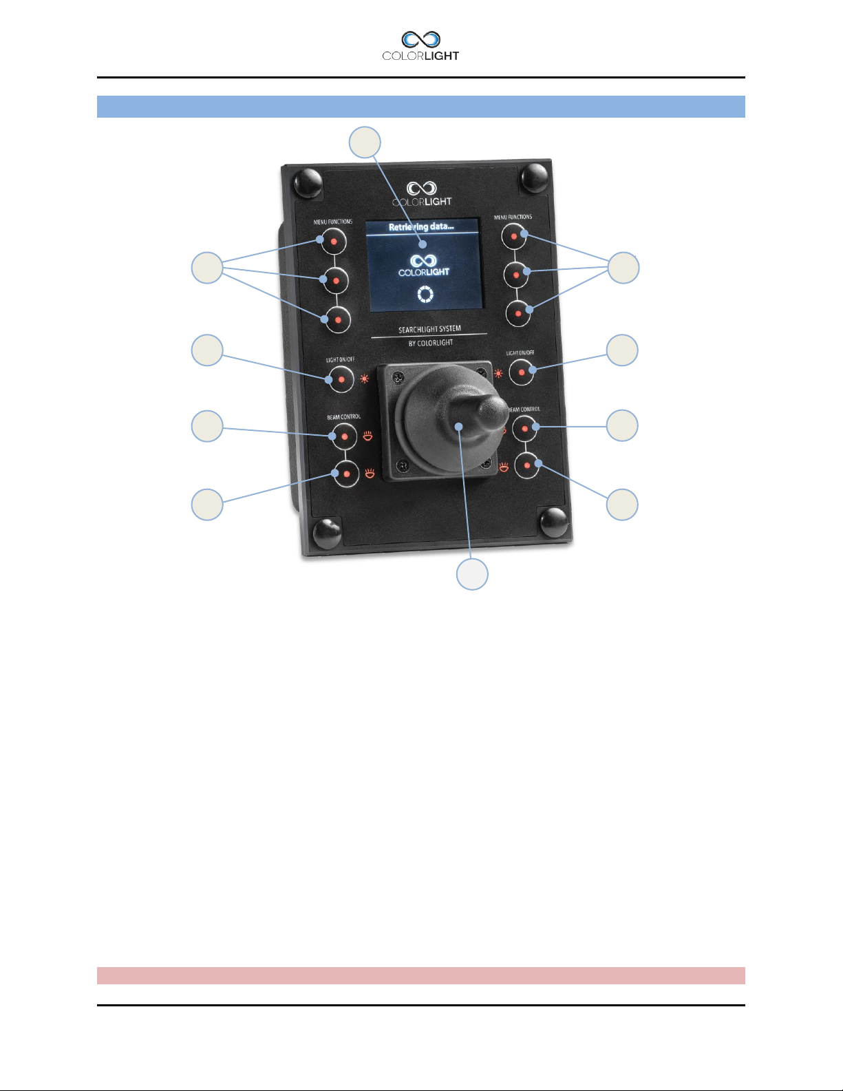
OPERATOR PANEL, OVERVIEW 5.
1. "Soft button": the function appears in the display window next to the button.
2. Left lamp on/off, (if “Single lamp mode” = On *1).
3. Left light increase intensity (Dim up in steps *2 ).
4. Left light decrease intensity (Dim down in steps *2).
5. Right lamp on/off, (if “Single lamp mode” = On *1).
6. Right light increase intensity (Dim up in steps *2).
7. Right light decrease intensity (Dim down is steps *2).
8. Joystick (”Hall effect” proportional).
9. Display (TFT 2,4”).
*1 See 15.8.5.5 Single lamp mode .
*2 LED dim levels are 25%, 50% 75% of max intensity. When light is lit the Intensity always starts at 100% (max)
regardless of previous dim level.
Note: Several sections of the manual refer to the above figures
Page 10 INSTALLATION & USER'S MANUAL CLITE2
Page 11
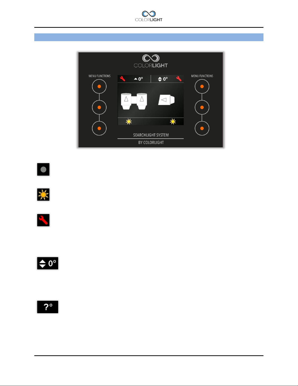
DISPLAY SYMBOLS AND MESSAGES 6.
Symbol for switched off white light.
Symbol for switched on white light.
Symbol for any electro-mechanic error. Might be referred as an over voltage or
over current for motor drivers. Communication error with motor drivers will result in
the same symbol. This error symbol can be reset by simply enter the main menu
and select status. Then press “dismiss”. If over current have occurred the problem
might be referred as a stucked lamp housing – check for any icing issues. Each
axis has its own symbol showing in upper left or right corner of the display.
This symbol and a similar symbol indicate the direction of the lamp housing both
for the vertical axis and for the horizontal axis. The arrows in the shown symbol
indicate the elevation angle for the vertical axis according to the horizontal-plane.
For the horizontal symbol and axis these small arrows indicate if the housing is
directed to the left, front, right or back of the centerline.
If the arrows are replaced by question marks then the system needs to be
internally calibrated. The easiest way to do the internal calibration is by simply
choose the “Park” in the quick start menu, please see 14.6 Off and park.
INSTALLATION & USER'S MANUAL CLITE2 Page 11
Page 12

Message
Fault
Communication error
Transmission issues on the CAN bus
Over current
Overcurrent protection triggered, movement blocked
Over voltage
Overvoltage protection triggered, voltage to searchlight motordriver/s
have exceeded its maximum value.
Under voltage
Undervoltage protection triggered, voltage to searchlight
motordriver/s has fallen below its minimum value.
OPWDT (message in box only)
Ethernet communication broken to all panels, see (4.1) OP WDT.
Fault auto-resets if contact is restored with at least one panel
Ebox alarm relay 6.1
The searchlights electrical and mechanical condition are constantly monitored and if there is a
malfunction in the system this is indicated by icons in the panel display with clarifying warning
messages found in the panels status menu.
The control box also has a relay output that can be connected to the boat monitoring system;
see the wiring diagram for connection details.
The following errors trigger the alarm output.
Page 12 INSTALLATION & USER'S MANUAL CLITE2
Page 13
CLITE2 IR (camera house)
CLITE2 Standard
fixed the searchlight, remove the
INSTALLATION 7.
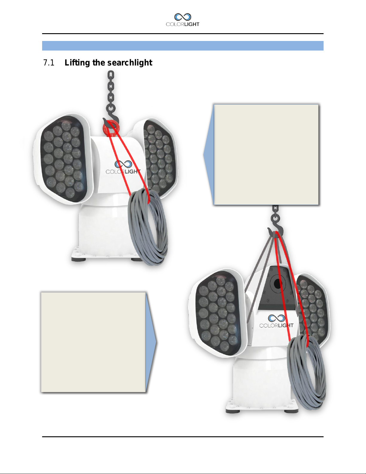
Lifting the searchlight 7.1
Preferable lift the searchlight by
the temporary lift loop on top of
the center house. After safely
lift loop.
During the lift, the searchlight
cables must be secured to the
hook to avoid straining and
damage on the cable glands.
The picture on the right shows
how to place the lifting slings
when there is no lift loop
available.
Also in this case the searchlight
cables must be secured to the
hook to avoid straining and
damage on the cable glands.
INSTALLATION & USER'S MANUAL CLITE2 Page 13
Page 14
1
2
1
17mm ratchet wrench × 1
2
17mm wrench × 1
3
4
CLI-30001, ANTI VIBRATION KIT 8.
Service instruction no: CLI-30001
Revision date: 2016-02-10
Applicable models: CLITE2, CL20-11, CL25-**, CL35/38-**
Spareparts needed (refer to CL spareparts list)
Tools and supplies required:
Important information
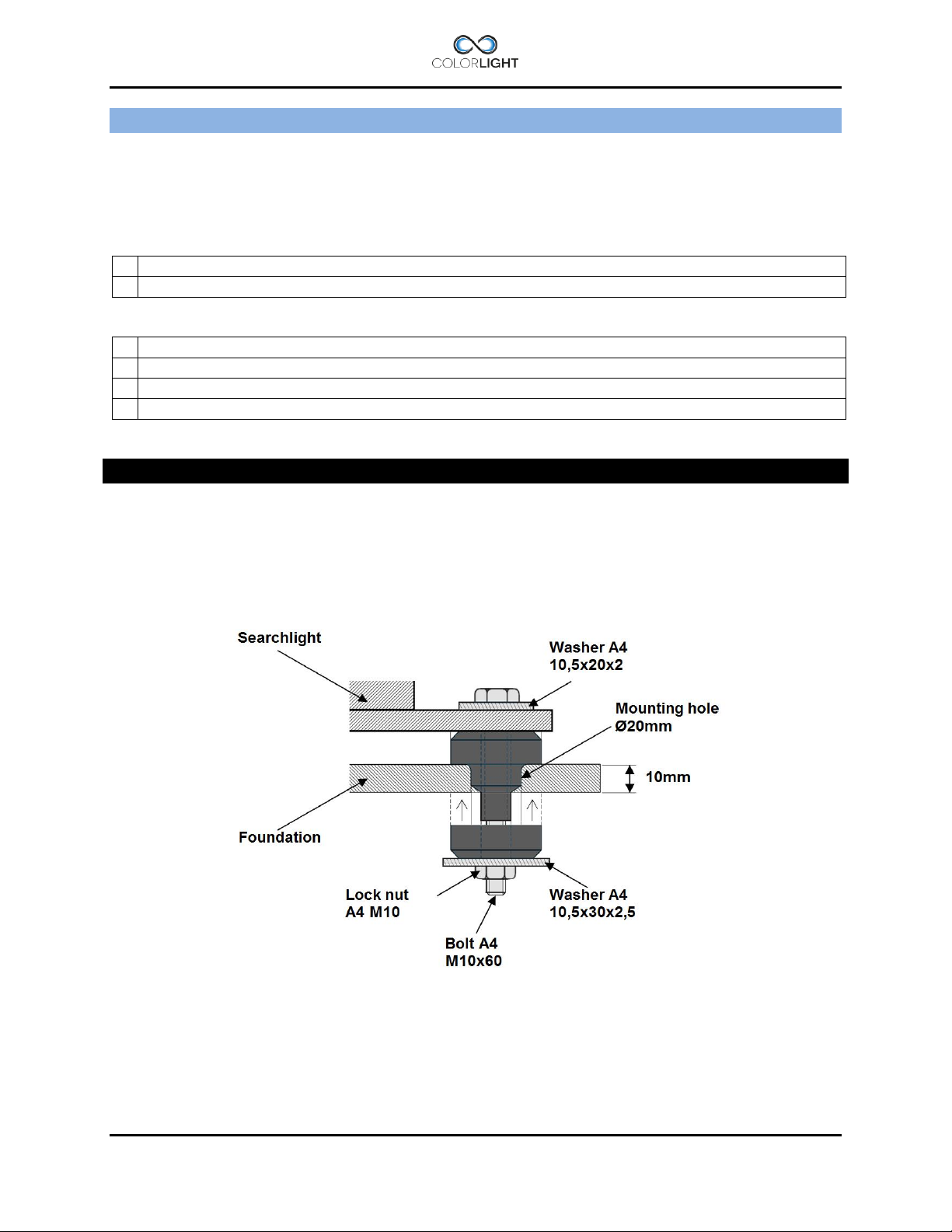
This instruction shows how to install the anti-vibration kit which consists of four dampers with
integrated stainless steel tubes.
The dampers main function is to absorb the harmful vibrations that can damage the mechanics
and shorten the life of the bulbs (CL20, CL25 CL35/38). Searchlight installations without
dampers will uncompromisingly, void the warranty.
Figure 1
1. Overview of the damper assembly and its parts.
Page 14 INSTALLATION & USER'S MANUAL CLITE2
Page 15
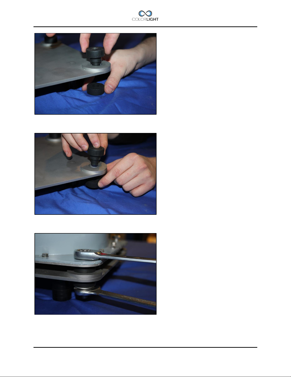
2. Push the dampers tube part thru the mounting holes in the foundation.
3. Mount the dampers rubber part from other side of the foundation.
4. Lower the searchlight on top of dampers and mount bolt washers and nuts as shown in
figure 1.
INSTALLATION & USER'S MANUAL CLITE2 Page 15
Page 16
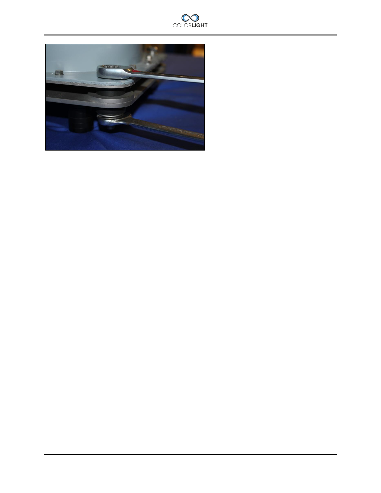
5. The lock nut is tightened with two wrenches size 17mm, tighten nut firmly.
The dampers rubber part will be compressed slightly, after assembly the searchlight will be
rigidly secured but still resistant to vibrations.
Page 16 INSTALLATION & USER'S MANUAL CLITE2
Page 17
ELECTRICAL SYSTEM 9.
IMPORTANT!
The electric supply to the e-box must be disconnected before beginning any work inside
the box; it’s not enough to turn off the internal main switch.
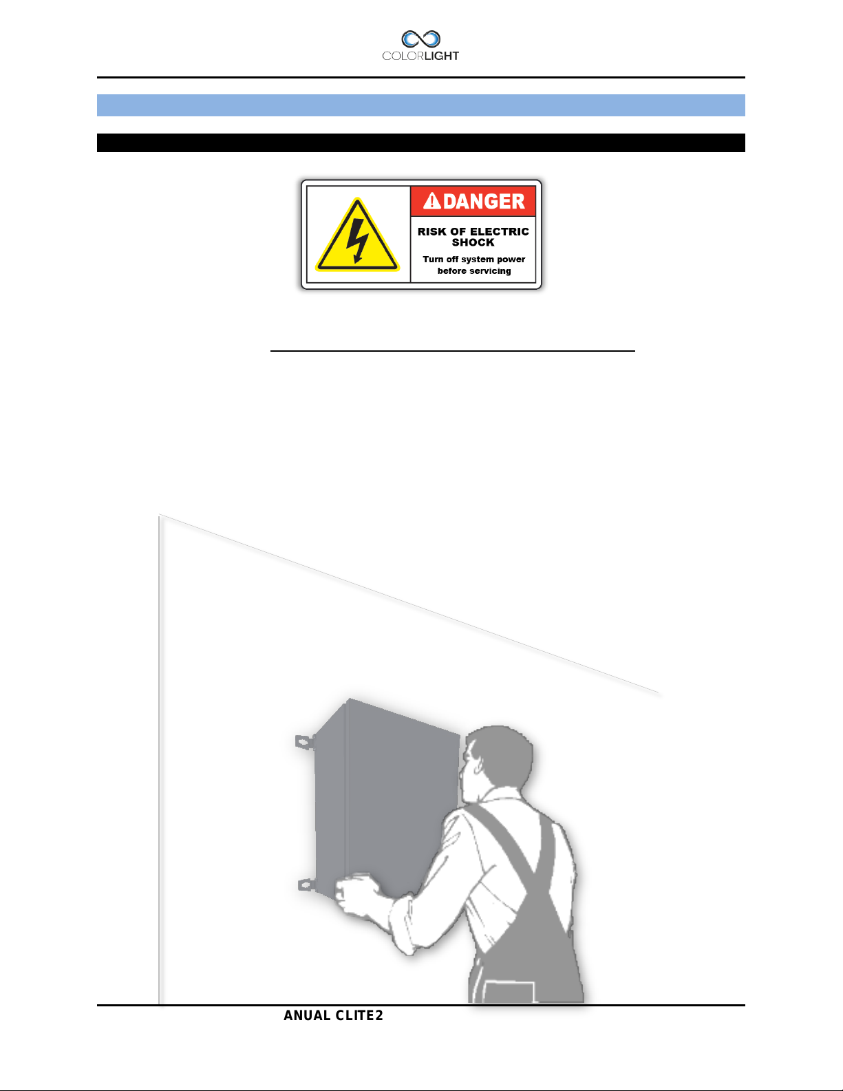
Electrical box mounting position 9.1
The electrical control box must be mounted on a wall as shown below, do not mount horizontally
on the floor or in ceiling as this leads to reduced airflow with increased risk of overheated
components.
INSTALLATION & USER'S MANUAL CLITE2 Page 17
Page 18
1
Screwdriver 0,6×3,5 mm
2
Adjustable wrench type Bacho 8071
3
Wrench 13 mm
4
CLITE2 Electrical Box (24Vdc)
EMC Gland Shield Connection
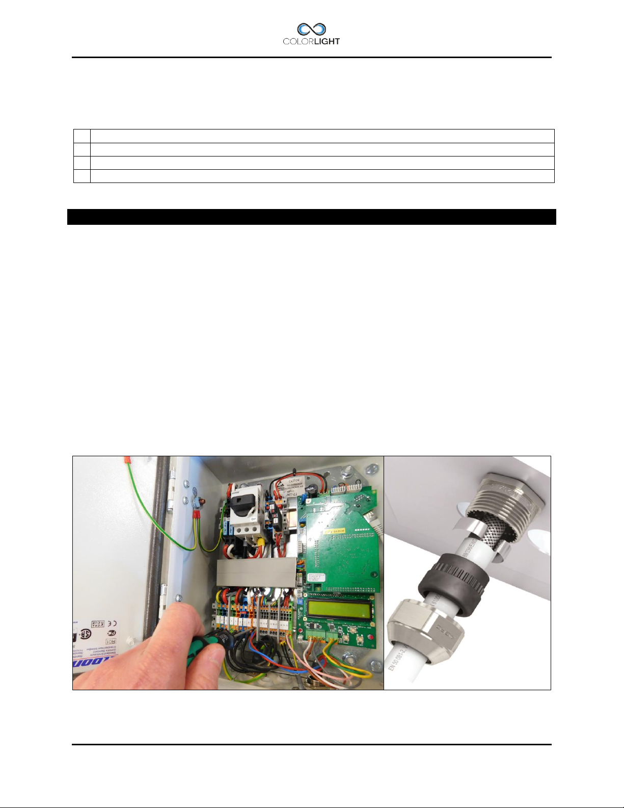
Electrical box installation 9.2
Tools and supplies required:
Important information
The complete system is undergoing final testing before delivery and therefore has the
searchlight cables installed in box.
1. Ensure that the switch Q01in box is set to off.
2. Remove all the cables in the terminals, the terminals are push-in type and the wire is
released easily by pressing the orange button with a screwdriver while pulling lightly in
the wire.
3. Loosen the cable glands with an adjustable wrench and pull out the cables.
4. Mount the electric box on a firm foundation with the help of the wall brackets.
5. Install in reverse order and pay special attention so that the cables shields are mounted
correct in the cable glands, see figure 2 below for guidance.
Cables are connected according to the wiring diagram and double-checked before the
power is turned on using the main switch Q01 in the electric box.
Page 18 INSTALLATION & USER'S MANUAL CLITE2
Page 19
Relay NC
Relay NO
Relay Common
RS232
RS485*
Opto 1A ->
Opto 1C <Opto 2A ->
Opto 2C <24Vdc
0V
24Vdc from
PSU
To system
Fuse T6,3A
Relay driver
Right(CL20)
Relay driver
Left(CL20)
Signalcable
to searchlight
Buttons for
navigation
Left LED Controlsignal
0-10V
Right LED Controlsignal
0-10V
Alarm Output
Fan control*
2
(grey)
*1 Standard setting.
*2 Wire is installed but has no function on CLITE2.
RJ45 Ethernet connection
connector in enclosure
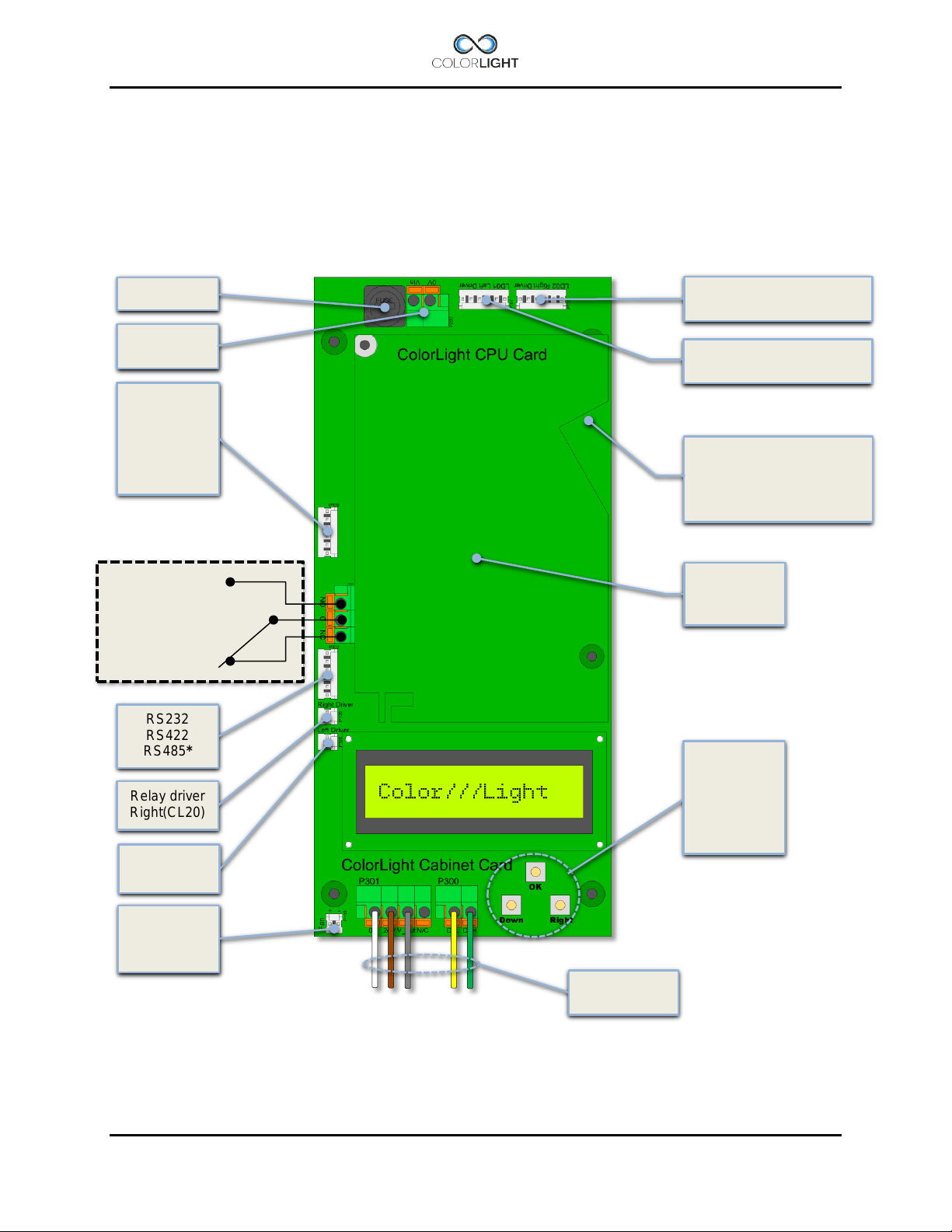
Cabinet card 9.3
Colorlights control system is stable and future-proof and the cabinet card is equipped with a
number of inputs and outputs as to allow the communication with the searchlight but also
communicate with computers, radio receivers, limit switches (via optocoupler) etc.
On the output side, we have relay controlled alarm output (NO, NC) for external alarm handling
and outputs for controlling relays (via optocoupler).
RS422
fan in box
+24Vdc (brown) 0V (white)
CAN H (green) CANL (yellow)
(connects with patchcable
to keystone pass-through
CPU Card
Menu
navigation
See:
Menu
INSTALLATION & USER'S MANUAL CLITE2 Page 19
Page 20
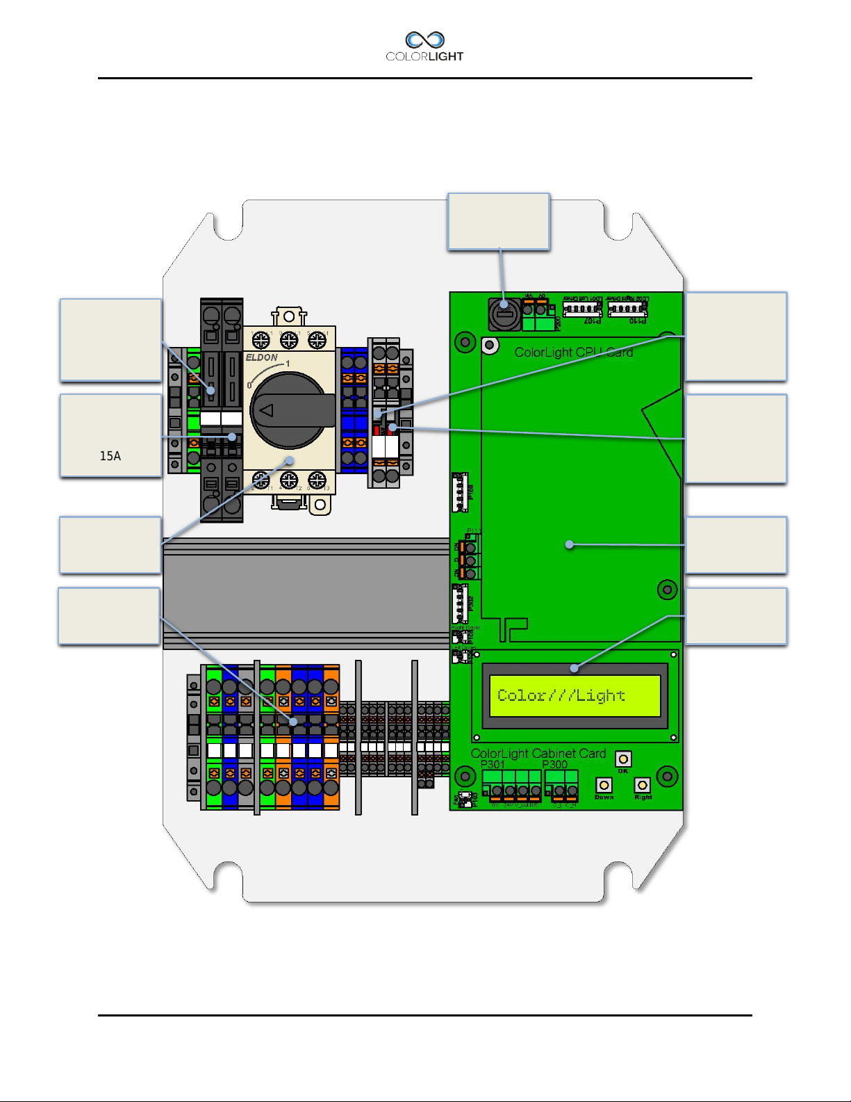
Light fuse F02
(Ext 24V for IR
window heater)
Light fuse F01
1 2 3 4 5 6 7
9
10
11
12
13
14
15
16
17
18
19
20
21
F03
F04
F01
F02
Terminal Group
Cabinet Card
CLITE2 electrical-box overview (24VDC) 9.4
for LD01
(Left light)
15A
Fuse T6,3A
Fuse F03
(Ext 24V for
OP3GS etc.)
T2A
for LD02
(Right light)
15A
Main switch
Q01
X01
Fuse F04
T2A
CPU Card
Page 20 INSTALLATION & USER'S MANUAL CLITE2
Page 21
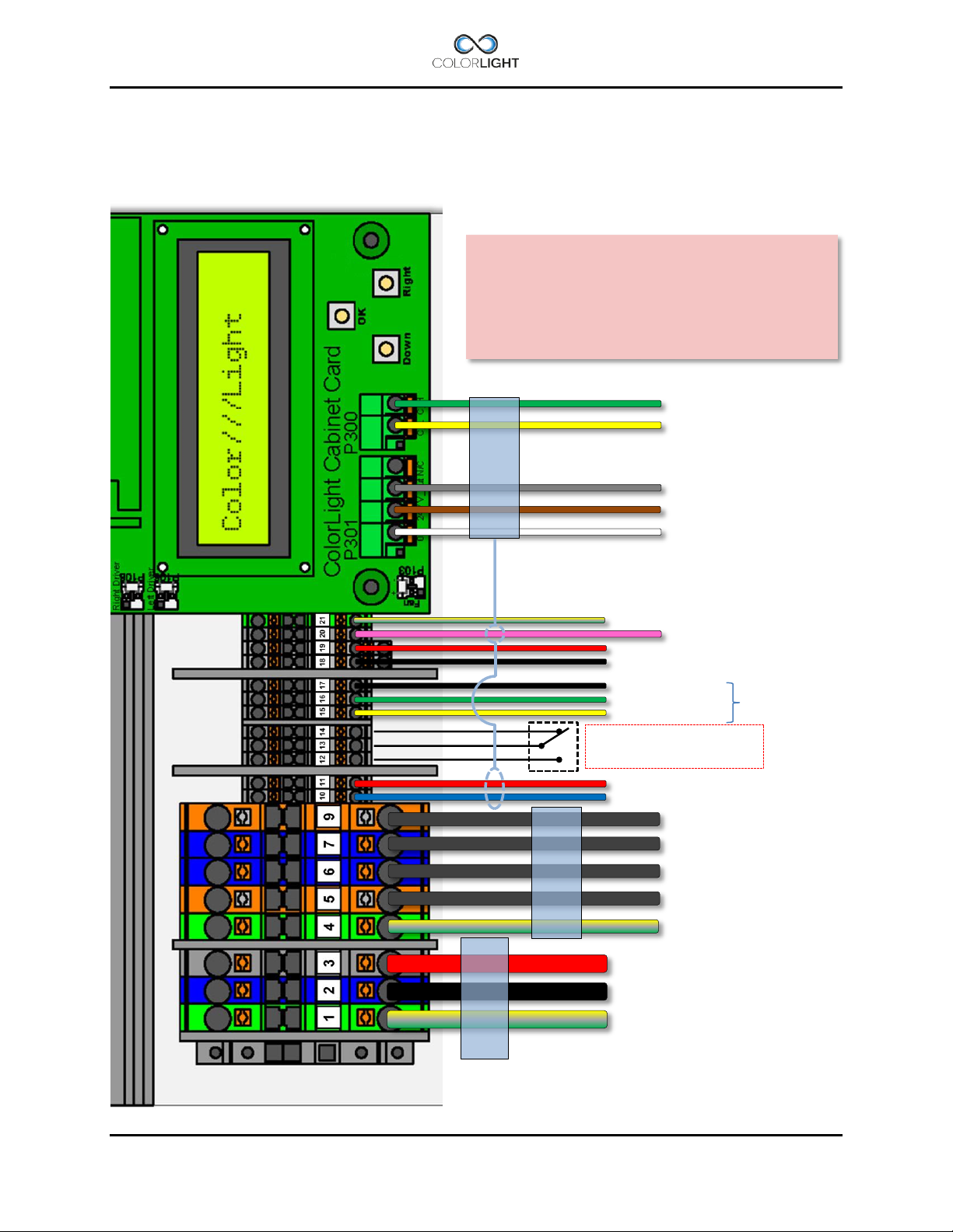
#3- 24V (+)
#2- 0V (-)
#1- Earth (PE)
#9- LD02 + (wire marked “4”)
#7- LD02 – (wire marked “3”)
#6- LD01 – (wire marked “2”)
#5- LD01 + (wire marked “1”)
#4- Earth (PE)
#11 – Control signal for LED (RIGHT)
#10 – Control signal for LED (LEFT)
MAINS-CABLE
24VDC
SEARCHLIGHT
POWER-CABLE
SEARCHLIGHT
SIGNAL-CABLE
#14 – Alarm output (NC)
#13 – Alarm output (COM)
#12 – Alarm output (NO)
#17 – GND
#16 – RS232/485*1
#15 – RS232/485*1
#19 – 24Vdc for panels, Ethernetswitch
#18 – 0V
#21 – GND for panel
#20 – 24Vdc for cam window heater
CAN H to searchlight electronics
CAN L to searchlight electronics
Fan control voltage UV *2
24Vdc to searchlight electronics
0V to searchlight electronics
*1 Standard setting.
*2 Wire is installed but has no function on CLITE2.
Wireless receiver or
solution
Searchlight or Ebox serial number from
-
See the system wiring diagram for more details.
CLITE2 electrical-box connection (24VDC) 9.4.1
This connection diagram shows our standard connection for CLITE2 with electrical box supplied
with DC voltage. Deviations may occur for customized solutions.
The wiring on this page is valid only for
CLITE2 systems delivered from May 2016 with
IMPORTANT
16003863
INSTALLATION & USER'S MANUAL CLITE2 Page 21
integrated bridge-
Page 22
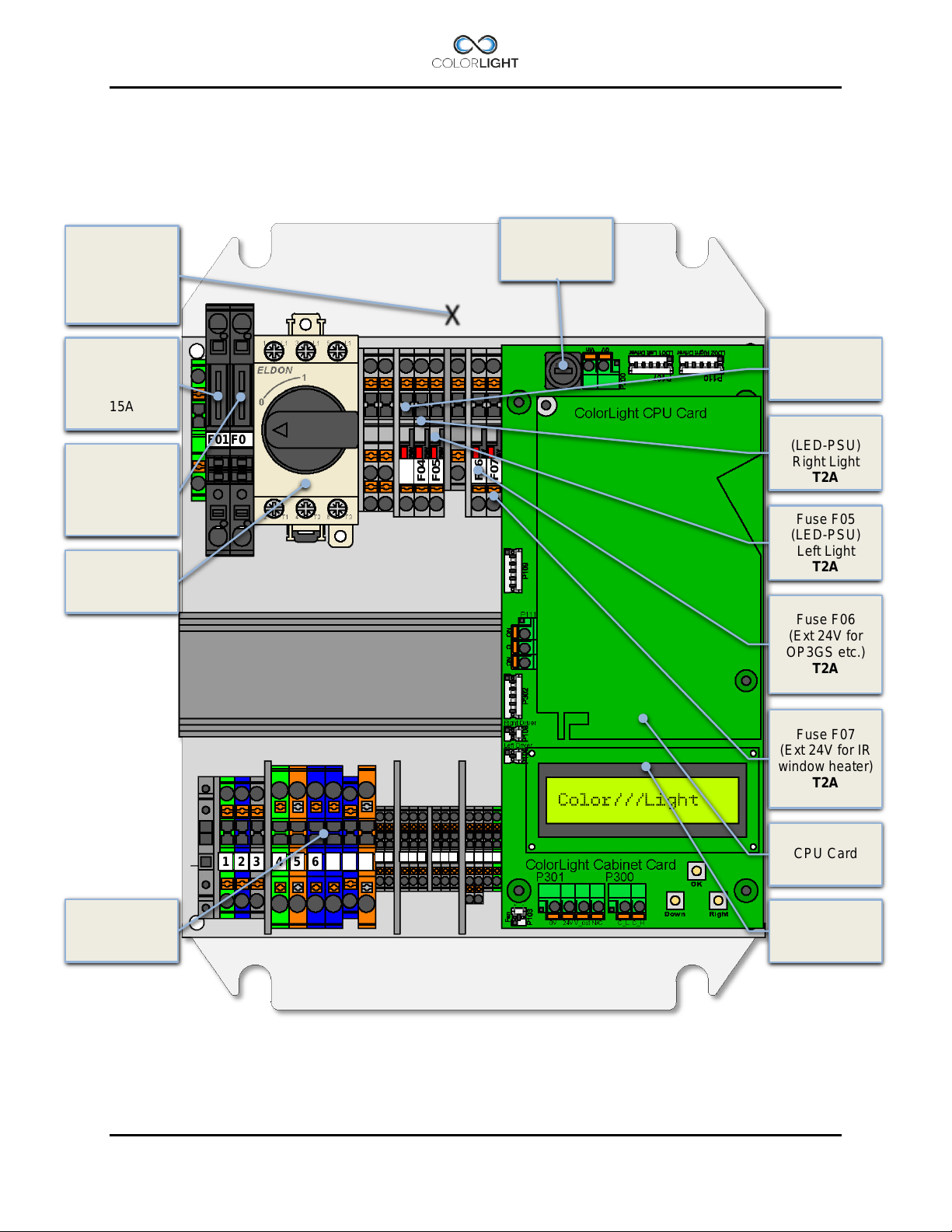
1 2 3 4 5 6 7 8 9
10
11
12
13
14
15
16
17
18
19
20
21
F03
F04
F05
F06
F07
F01
F02
T2A
Fuse F04
T2A
Fuse F05
T2A
(Ext 24V for IR
window heater)
Cabinet Card
Light fuse F01
Power supply E-
Under top-plate
X
Light fuse F02
Terminal Group
CLITE2 electrical-box overview (100-240VAC) 9.5
box
240W/24Vdc
Fuse T6,3A
LD01
(Left light)
15A
LD02
(Right light)
15A
Main switch
Q01
Fuse F03
(PSU)
(LED-PSU)
Right Light
(LED-PSU)
Left Light
Fuse F06
(Ext 24V for
OP3GS etc.)
T2A
Fuse F07
T2A
CPU Card
X01
Page 22 INSTALLATION & USER'S MANUAL CLITE2
Page 23
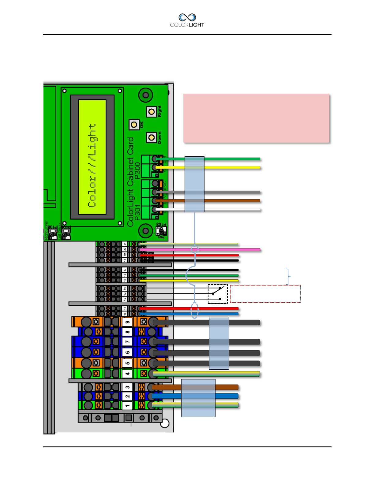
#3- L
#2- N
#1- Earth (PE)
#9- LD02 + (wire marked “4”)
#7- LD02 – (wire marked “3”)
#6- LD01 – (wire marked “2”)
#5- LD01 + (wire marked “1”)
#4- Earth (PE)
#11 – Control signal for LED (RIGHT)
#10 – Control signal for LED (LEFT)
SEARCHLIGHT
SIGNAL-CABLE
#14 – Alarm output (NC)
#13 – Alarm output (COM)
#12 – Alarm output (NO)
#17 – GND
#16 – RS232/485*
1
#15 – RS232/485*
1
#19 – 24Vdc for panels, Ethernetswitch
#18 – 0V
#21 – GND for panel
#20 – 24Vdc for cam window heater
CAN H to searchlight electronics
CAN L to searchlight electronics
Fan control voltage UV*2
24Vdc to searchlight electronics
0V to searchlight electronics
MAINS-
240VAC
SEARCHLIGHT
POWER-CABLE
*1 Standard setting.
*2 Wire is installed but has no function on CLITE2.
Wireless receiver or
solution
Searchlight or Ebox serial number from
-
See the system wiring diagram for more details.
CLITE2 electrical-box connection (100-240VAC) 9.5.1
This connection diagram shows our standard connection for CLITE2 with electrical box supplied
with DC voltage. Deviations may occur for customized solutions.
The wiring on this page is valid only for
CLITE2 systems delivered from May 2016 with
IMPORTANT
16003863
INSTALLATION & USER'S MANUAL CLITE2 Page 23
integrated bridge-
100-
CABLE
Page 24
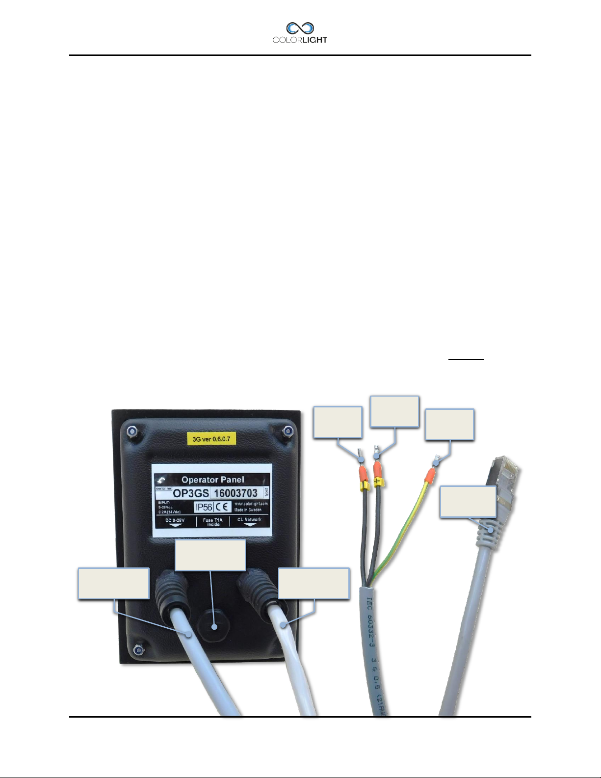
Wire#1
0v (-)
Wire#2
24Vdc (+)
Earth-
wire
RJ45
Connector
Ethernet Cable
Power Cable
Gore protective
membrane vent
Operator panel connections 9.6
The operator panel is designed to be immersed into the bridge panel, for dimensions, see
drawing in section 17.2.1 Operator Panel.
The following connections are available on the back of the panel:
1. Power supply 9-28 VDC via local power supply on the boat or 24VDC via terminals in
the E-box. One of the benefits of supplying power to the panel from the box is that the
panel will be de-energized together with the e-box via the main switch.
2. Ethernet connection directly to the electrical cabinet or Ethernet switch via RJ45
connector. Shielded Keystone Modular Feed through Coupler, RJ45-RJ45 included.
3. Earth connection to the panel, this is needed to suppress electrical disturbances and
prevent ESD discharge damaging.
Electrical protection:
The panel is protected against wrong polarity and over-current protected by an internal, type:
T1A (Slow-Blow glass fuse 5x20mm).
Page 24 INSTALLATION & USER'S MANUAL CLITE2
Page 25
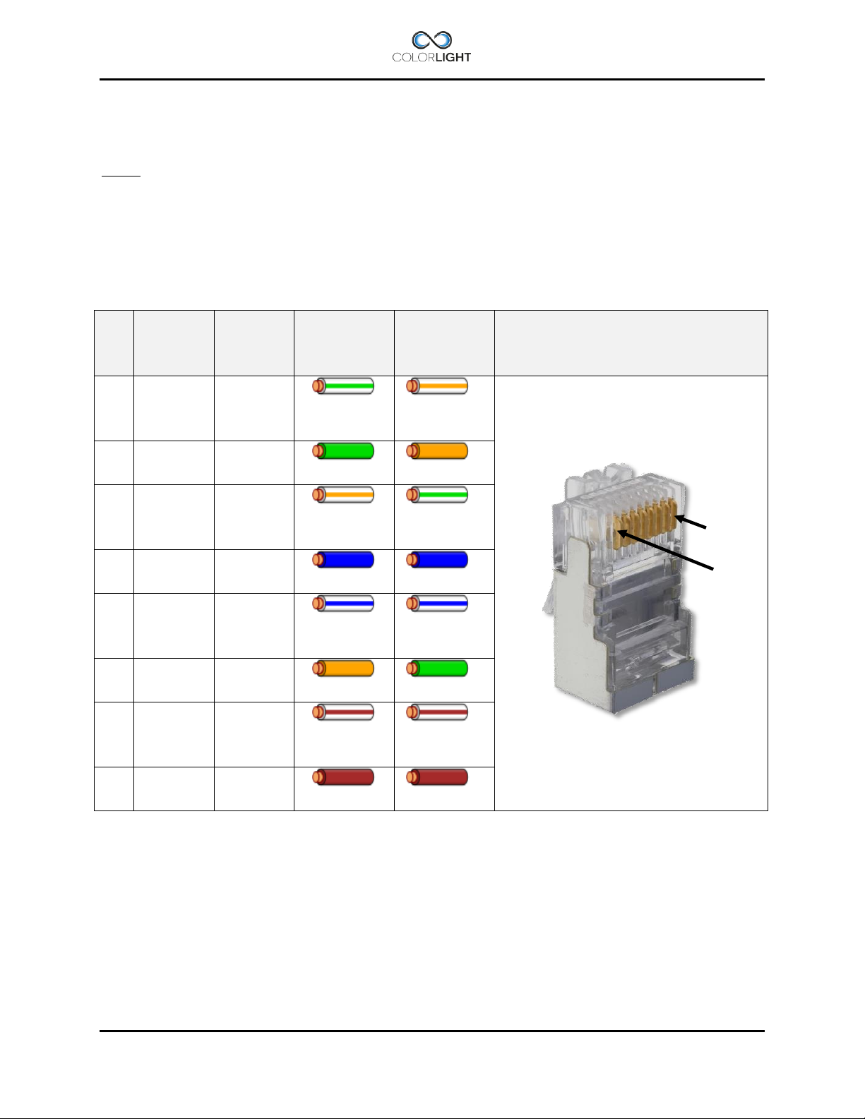
Pin
T568A
Pair
T568B
Pair
T568A
Color
T568B
Color
Pins on plug face
1 3 2
white/green
stripe
white/orang
e stripe
2 3 2
green solid
orange solid
3 2 3
white/orang
e stripe
white/green
stripe
4 1 1
blue solid
blue solid
5 1 1
white/blue
stripe
white/blue
stripe
6 2 3
orange solid
green solid
7 4 4
white/brown
stripe
white/brown
stripe
8 4 4
brown solid
brown solid
1
8
Ethernet wiring 9.7
Colorlight searchlight systems should be connected to their own dedicated network; they should
never be connected into the vessels existing computer network.
An Ethernet cable supplied from Colorlight complies with the standard TIA/EIA-568-B and is
always tested together with the complete searchlight system to ensure full functionality.
If customers choose to assemble their own Ethernet cables they must be of type FPT Cat5 or
better and the connections should be done according to the following information.
Note that the only difference between T568A and T568B is that pairs 2 and 3 (orange and
green) are swapped. Both configurations wire the pins "straight through", i.e., pins 1 through 8
on one end are connected to pins 1 through 8 on the other end. Also, the same sets of pins
connect to the opposite ends that are paired in both configurations: pins 1 and 2 form a pair, as
do 3 and 6, 4 and 5, and 7 and 8.
One can use cables wired according to either configuration in the same installation without
significant problem. The primary thing one has to be careful of, is not to accidentally wire the
ends of the same cable according to different configurations
INSTALLATION & USER'S MANUAL CLITE2 Page 25
Page 26
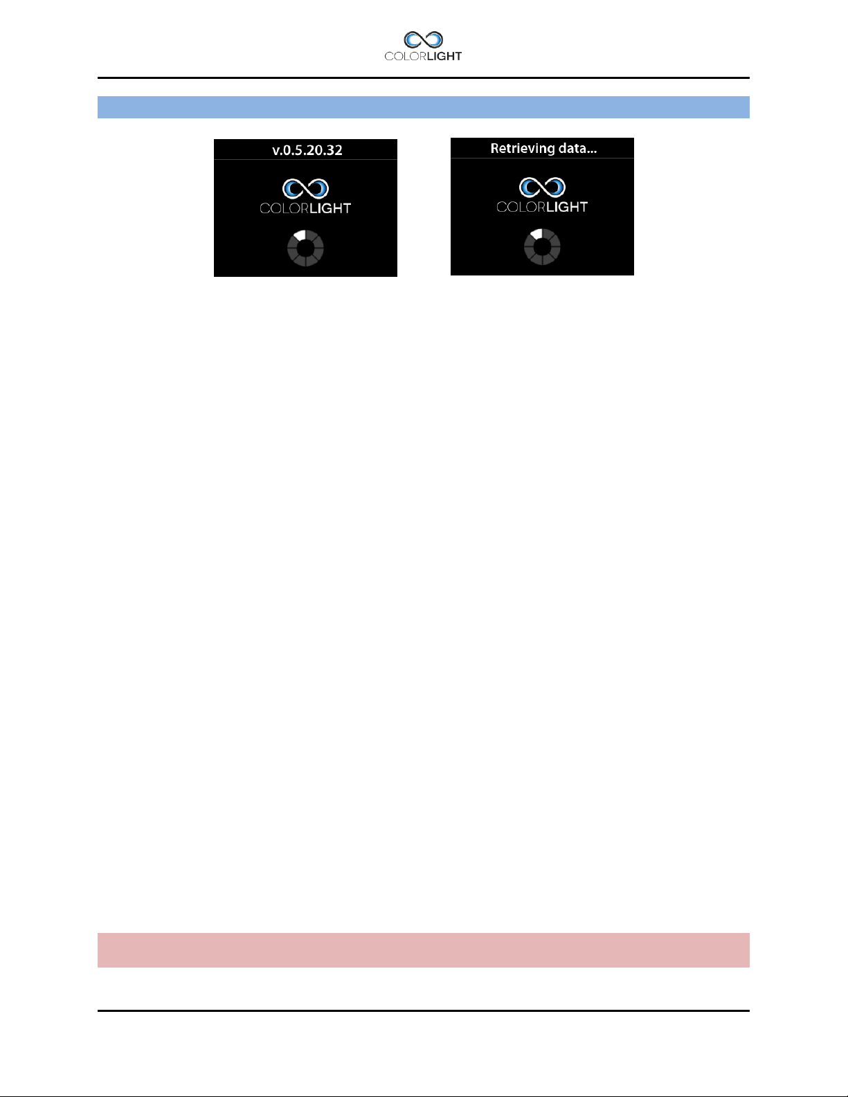
ACTIONS AFTER INSTALLATION AND POWER FAILURE 10.
At system startup, the panels will start to scan the network to find connected electrical boxes,
during this time, the panel software version will be displayed.
If not the panel made contact by displaying home screen within 30 seconds, it may be due to
the following:
Electrical box is not turned on, applies only if the panel has a separate power supply.
There are problems in the network cabling between the electrical box and the operator
panel.
Automatic recovery of stored searchlight position in panel. 10.1
A new feature was introduced with the release of the control software, v 0.5.23.35 for ebox and
v 0.6.0.7 for the operator panels, from these versions this is a standard feature*.
With this new feature the system always stores the searchlight position after the movement has
been idle for 20 seconds. The position is stored in in a non-volatile memory.
When the system is restarted after power loss, the last stored position will automatically be
reloaded in to the panel.
The panel position indicator differs from the actual position of the 10.1.1
searchlight.
At boot up, the panel position indicator can differ from the searchlight actual position for the
following reasons:
The system power was interrupted in the middle of a joystick maneuver.
The searchlight had just been maneuvered but the power interruption occurred before
the 20 seconds elapsed and therefore the new position was not stored.
The searchlight axis has turned away from latest stored position while it was switched
off, manually or by wind gusts.
Positional deviations depending on the above will be automatically corrected when the
next “Park” is commanded.
Note: always synchronize before setting sweep*, fixed positions* or surveillance* to ensure that
the system is not rebooted with deviating positions, please see 10.2 Synchronize the system.
*Older systems can be updated, please contact us for more information.
Page 26 INSTALLATION & USER'S MANUAL CLITE2
Page 27
Synchronize the system 10.2
The easiest way to synchronize the system after reboot is to enter the quick start menu and
select the “Park” function; the system will then activate the horizontal and vertical movement
until the searchlight absolute position sensors sends their signals back to the control system
and thereby updating it with the correct positioning.
If a parking position has been set, the searchlight will end this procedure by parking.
If necessary the origin can be set after the steps above to give an accurate readout of the
indicator. To set the origin, please see 15.8.5.1 Store origin.
INSTALLATION & USER'S MANUAL CLITE2 Page 27
Page 28

STARTING SYSTEM 11.
When the system is in sleep mode the buttons and symbols glows with orange light and the
display is totally shut down to save power. Buttons and symbols are always active but dimmed
to a lower intensity during sleep mode.
Pressing any button on the operator panel will activate the system and the display will now show
the position indicator image, buttons and symbols are now brighter.
Buttons, symbols and display intensity can be adjusted, please see 15.8.1 Backlight brightness.
Page 28 INSTALLATION & USER'S MANUAL CLITE2
Page 29

JOYSTICK FUNCTIONS 12.
The joystick (8) moves the searchlight horizontally and vertically. There are no limitations to the
movement of the searchlight thanks to the slip ring technology developed by Colorlight.
The more the joystick is moved to its end position the faster the searchlight rotates.
Searchlight rotation speed can be set, see 15.8.4 Maximum rotation speed.
The vertical axis reaction to the joysticks movement can be reversed if decided by operator. To
change this reaction please see 15.8.3 Joystick direction.
The joystick can also be used to navigate in menus containing more than one choice.
Move the joystick up or down to navigate in the menu. In most menus joystick moved to the right
will act as “OK” button and moved to the left will go back one step as the “Back” button.
INSTALLATION & USER'S MANUAL CLITE2 Page 29
Page 30

SWITCH ON LIGHT 13.
This searchlight is equipped with two LED lamp modules.
As default both lamps will be turned on by pressing button (2) or (5), both lamps will be soft
started with a slight delay in between *1, no matter which button is used.
To turn off the light, press button (2) or (5) again.
There are however occasions when it may be useful to give each lamp a dedicated light button,
this setting is done in the "Single lamp mode" menu, please see 15.8.5.5 Single lamp mode.
In the bottom part of the display there are two sun-symbols that indicates the status of the LEDlamps.
*1 The LED soft-start function is optimized to prevent a high inrush current during startup.
Page 30 INSTALLATION & USER'S MANUAL CLITE2
Page 31

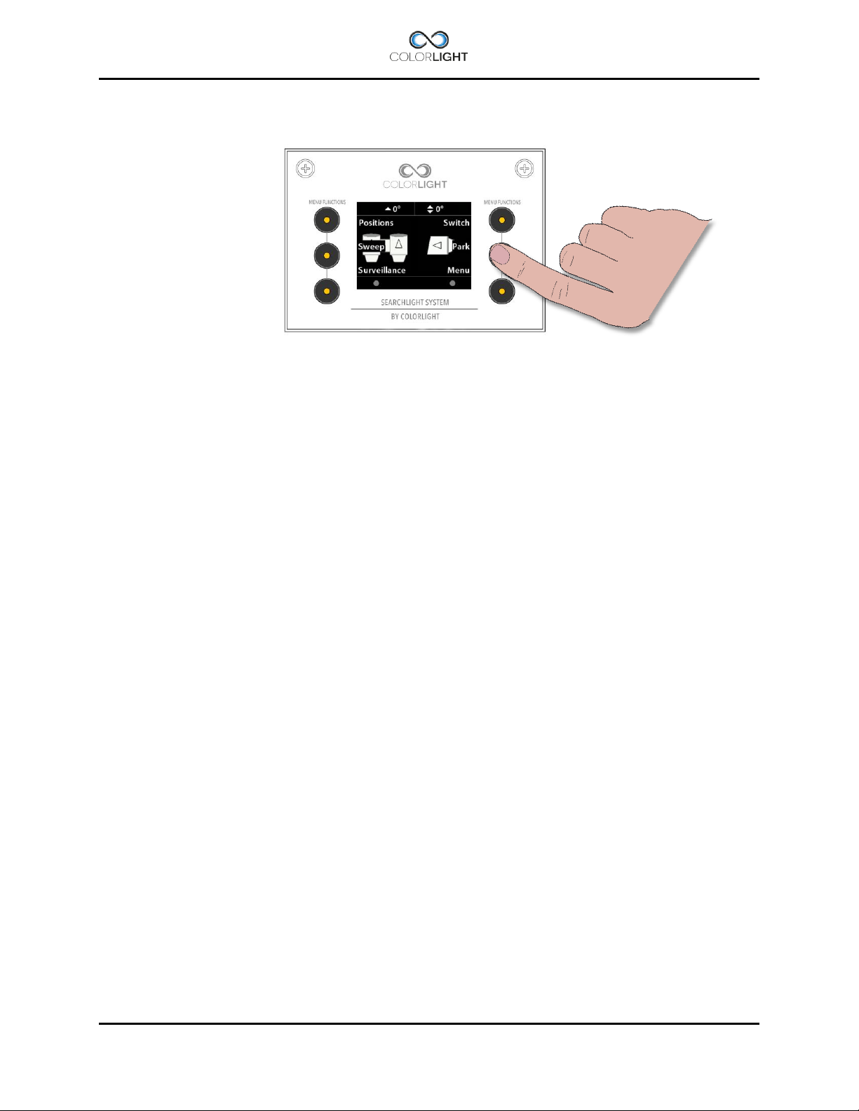
QUICK START MENU 14.
The operator panel features a quick start menu where you can reach some of the searchlights
functions.
To open up the quick start menu, press any of the quick start menu buttons (1) when showing
the logo or indicator page. The quick start menu will close after 5 seconds.
Fixed positions (optional function) 14.1
Fixed position is an option for the Colorlight Searchlight System and can only be accessed if
activated.
There are up to four different programmable fixed positions in Colorlight Searchlight System.
Go to fixed position 14.1.1
To enter the "Fixed Light Position" submenu, open up the quick start menu and press the
upper left button "Positions".
There are up to four fixed position memories (A, B, C and D) which can be individually
programmed.
By selecting one of the positions the menu will change and show the current direction of the
searchlight in degrees and move the searchlight to this preprogrammed position automatically.
INSTALLATION & USER'S MANUAL CLITE2 Page 31
Page 32

Store fixed position 14.1.2
If no position has been stored or the searchlight is already at the stored position it will not move.
To store a new or change a fixed position, enter one of the regarded memories (A, B, C or D) in
the menu. If there is already a preprogrammed fixed position stored at the selected memory, the
searchlight will start to move to that position. Either select a free memory or, if you want to
change this item, take control over the searchlight by moving the joystick (also aborting an
eventual movement of the searchlight).
Now – by using the joystick - move the searchlight to the desired new position and press
“Store”.
The current position is now stored.
Note that you always overwrite a previously stored position.
Page 32 INSTALLATION & USER'S MANUAL CLITE2
Page 33

Sweep (optional function) 14.2
Sweep is an option for the Colorlight Searchlight System and can only be accessed if activated.
At sweep mode, the searchlight automatically moves back and forth between two individually
programmable positions in the horizontal plane.
New Sweep 14.2.1
To enter the "Sweep" submenu, open up the quick start menu and press the left middle button
"Sweep".
To start a new sweep, navigate down to “New” in the “Sweep” menu and press “OK”.
The default setting for a sweep is a horizontal sweep of 20°.
To stop a sweep enter the "Sweep" submenu and choose “Stop” or just move the searchlight
by using the joystick.
To resume the sweep enter the "Sweep" submenu and choose “resume”.
INSTALLATION & USER'S MANUAL CLITE2 Page 33
Page 34

Modify sweep parameters 14.2.2
To modify the sweep angle and / or the center of the sweep enter the “Sweep” menu and
navigate down to “Modify”, press “OK”.
This menu changes the sweep angle and center point of the sweep, modification can be carried
out both during movement and while searchlight is standing still.
To change the center point of the horizontal sweep move the joystick to the left or right until the
desired center point is reached.
To change size of the sweep angle move the joystick up or down.
Press “OK” to save and update the searchlight with the new values.
Page 34 INSTALLATION & USER'S MANUAL CLITE2
Page 35

The default speed of the sweep is set to 50% of the maximum speed of the searchlight. To
change the speed of the sweep enter the “Sweep” menu and navigate down to “Speed”. Press
“OK” to enter the “Speed” submenu.
To change the speed move the joystick up or down to desired speed, press “OK” to update the
searchlight with the new speed.
Note: If the rotation speed is updated during runtime this will effect only after the searchlight has
reached its next end point.
INSTALLATION & USER'S MANUAL CLITE2 Page 35
Page 36

Surveillance (optional function) 14.3
Surveillance is an optional function for the Colorlight Searchlight System and can only be
accessed if activated.
This is an advanced sweep, where up to five different points, at any azimuth and elevation can
be set for surveillance.
Setting a new surveillance sweep 14.3.1
To set a new surveillance sweep the number of positions must first be set.
To enter the “Surveillance” submenu, open up the quick start menu and press the bottom left
button.
Navigate down to “Number of Positions to Use” and press “OK”.
Page 36 INSTALLATION & USER'S MANUAL CLITE2
Page 37

Select the requested number of positions (max. five) to be used in this surveillance sweep.
Press “OK” to save and return to the “Surveillance” submenu.
To set the positions in a surveillance sweep enter the “Positions” menu in the “Surveillance”
submenu.
The selected number of positions is shown in the display.
To set a position, enter the desired position, then move the searchlight to the by using the
desired position by the joystick. Press “Store” to store each position.
INSTALLATION & USER'S MANUAL CLITE2 Page 37
Page 38

After pressing “Store” a new menu will appear, “Pause Length”. This defines how long the
searchlight will rest at this position before starting to move to the next position. Pause length
can be set between zero and ten seconds.
Repeat this for the desired number of positions.
When done go back to the “Surveillance” submenu by pressing “Back”.
Navigate to “Start” and press “OK” to start the surveillance sweep.
The surveillance sweep will start from position one and go to position two and so until the
searchlight has come to the number set in “Number of Positions to Use”
14.3.2
Changing surveillance settings
Surveillance has a couple of different settings, “Loop Mode” and “Speed”.
In “Loop Mode” there are two choices, “Back and Forth” and “Repeat”.
To set “Back and Forth” or “Repeat” enter the “Surveillance” submenu then “Loop Mode”.
When using “Back and Forth” the surveillance sweep will go from position one to two and so on
until it reaches the last one set in “Number of Positions to Use”. Then it will start calling these
positions in reverse order!
When using “Repeat” the surveillance sweep will go from position one to two and so on until it
reaches the last one set in “Number of Positions to Use”.
From there it will start the same sequence at position one instead of going to the previous
position.
Page 38 INSTALLATION & USER'S MANUAL CLITE2
Page 39

Navigate to the preferred setting and press “OK” to save the setting and return to the
“Surveillance” menu.
“Speed” is where the speed of the rotation of the searchlight is set. Default setting is 50% of
maximum speed of the searchlight.
To change the actual speed of the surveillance sweep enter the “Surveillance” submenu then
“Speed”.
Change the setting by moving the joystick up or down in the speed menu until the requested
value is shown. The speed can be set between 5-100% of the maximum rotation speed.
Note: If the rotation speed is updated during runtime this will effect only after the searchlight has
reached its next end point.
INSTALLATION & USER'S MANUAL CLITE2 Page 39
Page 40

Switch 14.4
If there are more than one Colorlight searchlight in the system any operating panel can control
any of the connected Colorlight searchlights. Every searchlight should be given a unique name
during installation for this to work properly.
To enter the “Switch” submenu open up the quick start menu and press the upper right button.
In this menu all the available searchlights should be listed. To change which searchlight being
controlled, navigate to the desired searchlight and press “OK”.
The operating panel should now control the newly selected searchlight which is shown on the
indicator page.
Page 40 INSTALLATION & USER'S MANUAL CLITE2
Page 41

Slave 1
Slave 2
Master
Panel with sync activated
Synchronized control 14.5
This function is available in the “Switch” submenu if there is more than one Colorlight Search
Light in the network and at least one operator panel has the option "Synchronized control"
enabled. The feature gives the user control over multiple searchlights at the same time from a
single operator panel and can therefore obtain optimal light on the same area.
For this feature to be easy to handle, the searchlights should be given a unique name, for
example by mounting location on the boat, please see 15.8.5.3 Name system.
The following basic functions will be synchronized if “Sync” is enabled in the operator panel:
Horizontal and vertical movement based on position, i.e. there may be a small
discrepancy during real-time movement with joystick but the final position will always be
identical on all synced system when movement stops.
Light / on off, white light button will turn on and off all the white lights on master and
synchronized slaves and UV button does the same with any UV light.
Off and park, if the parking command in panel is selected, the master and all connected
slaves will simultaneously turn off the lights and park.
The Sweep, Fixed positions or Surveillance features will not be synchronized, but only started
on the searchlight in the network that the operator panel points to, even if this searchlight is the
master.
Important, the following settings must have been performed during installation or power failure
on each of the systems in the network before they can be included in the synchronized group
control.
Actions after installation or power failure please see 10. ACTIONS AFTER
INSTALLATION OR POWER FAILURE.
Store origin, please see 15.8.5.1 Store origin.
INSTALLATION & USER'S MANUAL CLITE2 Page 41
Page 42

To enter the “Switch” submenu open up the quick start menu and press the upper right button.
In this menu all the available searchlights should be listed. To change which searchlight being
controlled, navigate to the desired searchlight and press “OK”.
The operating panel should now control the newly selected searchlight which light status and
position is shown on the indicator screen.
Page 42 INSTALLATION & USER'S MANUAL CLITE2
Page 43

Set the master control searchlight on/off 14.5.1
The master is the searchlight that you actively control with your operator panel and it is the
master’s indicator and error message that is displayed in the operator panel display.
Light icons however, changes to the configurations that are available in the group at the
moment.
If the master has two white lights (11) and you add a slave who has one white and one UV (12),
the master's indicator field will immediately update so that there is a UV light available in the
group.
Once you have switched over to the searchlight which you want to be master in the system,
press the "Sync" button, In this case, we choose CL35 CENTER as our master.
The arrow in front of the selected CL35 CENTER tells us that this system is the "master" in the
network and if the sync function is activated all the slaves will follow the masters movement.
Important, to add and remove slaves, please see 14.5.2 Add and remove slaves.
To disconnect the master and run the CL35 CENTER searchlight as a single searchlight go into
the “Switch” submenu, navigate to the master searchlight and press the “Single” button.
INSTALLATION & USER'S MANUAL CLITE2 Page 43
Page 44

Add and remove slaves 14.5.2
Add or remove one or more slaves is done by entering the "switch" submenu and with the
joystick scroll through the list of available searchlights, If the searchlight in the list is not
connected in the synchronized group control, the text "Add" appears next to the top left button,
to add this searchlight to the group, press the "Add” button.
If the searchlight marked is already listed as slave in the group, the text "Remove” appears next
to the top left button, to remove this searchlight from the group, press the "Remove" button.
Page 44 INSTALLATION & USER'S MANUAL CLITE2
Page 45

Off and park 14.6
By pressing the button next to "Park", any lighted lamp will be turned off and the searchlight will
automatically look up the preprogrammed parking position, during this time you'll see
"Parking ..." in the bottom middle of the display.
When parked, the operator panel will turn off the display after a few seconds and the LEDs
behind the buttons will be dimmed to a lower intensity.
INSTALLATION & USER'S MANUAL CLITE2 Page 45
Page 46

MAIN MENU 15.
From the quick start menu, select "Menu" to enter the system's main menu.
To navigate in the main menu, use the joystick; push the joystick forward/up once to go up one
step in the menu and backwards/down to go down one step. Keep holding the joystick up or
down will scroll up and down in menus with “autorepeat”.
To confirm your choice use "OK" button and to leave the displayed menu, use the button
"Back". In many menus the joystick can be used as the “OK” button if moved to the right and as
the “Back” button if moved to the left.
Off and Park 15.1
Please see 14.6 Off and park for information regarding this menu choice.
Switch system 15.2
Please see 14.4 Switch for information regarding this menu choice.
Light Position 15.3
Please see 14.1 Fixed positions for information regarding this menu choice.
Sweep 15.4
Please see 14.2 Sweep for information regarding this menu choice.
Surveillance 15.5
Please see 14.3 Surveillance for information regarding this menu choice.
Page 46 INSTALLATION & USER'S MANUAL CLITE2
Page 47

Message
Fault
Remedy
Communication error
CAN bus transmission issues
Check for loose wires in the
electrical box and contact
Colorlight.
Over current
Overcurrent protection triggered,
movement blocked
Check that the searchlight is able
to rotate freely.
In winter, heavy icing can be the
cause of this error.
Over voltage
Overvoltage protection triggered,
voltage to searchlight motordriver/s
have exceeded 40Vdc.
Reset the error, if error recurs
repeatedly, please contact
Colorlight.
Under voltage
Undervoltage protection triggered,
voltage to searchlight motordriver/s
has fallen below 8,5Vdc
Reset the error, if error recurs
repeatedly, please contact
Colorlight.
Info 15.6
This menu shows information that is needed to be known during support from Colorlight or if any
optional functions should be added to the operator panel after purchase (more about this under
15.8.5.7 Options setup).
Status 15.7
This menu will give information in form of text messages if there is errors.in the system, it also
contains a “Lamp-hour counter” showing the accumulated total running time in hours for each
LED-module.
Errors can be reset from this menu by simply press the button marked “Dismiss”, if errors
persist despite resetting, contact Colorlight.
INSTALLATION & USER'S MANUAL CLITE2 Page 47
Page 48

Settings 15.8
This opens a new menu with six sub menus.
Backlight brightness (adjust the button´s/ display light intensity) 15.8.1
In this menu the intensity of the button LEDs and the display backlight can be adjusted between
5-100%.
The adjustment is done by moving the joystick forward for increasing the intensity and backward
to decrease. The selected intensity is confirmed with “OK”.
Language 15.8.2
The language in the display can be changed depending on which language sets that are
installed in the operator panel.
Currently, the following languages are available (Q2 2016):
English, Swedish, Chinese, French, German, Italian, Portuguese, Russian.
If you find that your language is missing, please contact Colorlight
Page 48 INSTALLATION & USER'S MANUAL CLITE2
Page 49

Joystick direction 15.8.3
Some operators want to have their joystick to move the lamp housing vertically in the same
direction as the joysticks physical direction:
(joystick up=lamp housing moving upwards), this is called “Inverted” in the menu.
Normally the joystick acts like an aeroplane joystick:
(joystick up=lamp housing moving downwards), this is called “Normal” in the menu.
INSTALLATION & USER'S MANUAL CLITE2 Page 49
Page 50

Maximum rotation speed 15.8.4
This menu gives the operator the opportunity to limit the actual maximum rotation speed of the
searchlight in relation to its absolute maximum rotation speed.
The adjustment is done by moving the joystick forward to change speed in increments of 5%
and backwards to decrease. Minimum speed is 20% and maximum 100%, when the choice is
confirmed with "OK", the display jump back to the previous "Settings" - menu.
Page 50 INSTALLATION & USER'S MANUAL CLITE2
Page 51

Installation 15.8.5
In this menu there are six sub menus each described below:
15.8.5.1 Store origin
This menu is used to calibrate the systems “ZERO” point for both vertical and horizontal axis.
Before the “Store origin” command is stored it is necessary that the synchronization between
operator panel and electrical box is done properly. The easiest way to do the synchronization is
by turning the system off with the “Park” command, please see 14.6 Off and park.
Start the system according to 11. STARTING SYSTEM (normal start). Now the position of the
lamp housings should be adjusted to be in level with horizontal plane and in direction straight
forward of the vessel (normally)! Then “Store origin” is executed and setting is stored.
INSTALLATION & USER'S MANUAL CLITE2 Page 51
Page 52

15.8.5.2 Store park position
This menu enables the storing of a park position (lamp housing pointing at any direction when
the “Park” command is selected.
Before changing the default park position it’s necessary that the synchronization between
operator panel and electrical box is done properly. The easiest way to do the synchronization is
by just turn the system off with the “Park” command, please see 14.6 Off and park.
From the default logo screen or display indicator*-screen, move the searchlight to the new
desired park position and when satisfied select menu>settings>Installation and enter sub
menu “Store park position”.
Press “OK” to save the new park position and return to the default logo screen or display
indicator*-screen
Suitable park position for CLITE2 is pointing straight ahead 0/0 degree; this is also the default
parking position
Page 52 INSTALLATION & USER'S MANUAL CLITE2
Page 53

15.8.5.3 Name system
The dedicated Colorlight network can contain several searchlights and operator panels.
To make the whole network easy to navigate; each electrical box and its corresponding
searchlight can be named to a well-known name for the operator.
The name is set by moving the joystick up and down to select correct character. To move to
next character in the name the joystick is moved to the right. Finish the name process and save
the name by select “OK” by pushing the button at the right bottom corner of the display.
INSTALLATION & USER'S MANUAL CLITE2 Page 53
Page 54

15.8.5.4 Start test sequence
This menu starts a test sequence which tests the movement of the lamp housings and focus for
each lamp house one at a time.
The test sequence will perform as follows:
At test sequence startup the lamp housing will be moved to parking position.
The horizontal axis will be rotated one full revolution clockwise.
The vertical axis will be rotated one full revolution clockwise.
The left lamp houses focus motor is activated during 10 seconds.
The right lamp houses focus motor is activated during 10 seconds.
The whole sequence above will be repeated 5 times before the test sequence is automatically
abandoned. Every even time the rotation will be anti-clockwise and every odd time the rotation
will be clockwise. During the test sequence the operator can switch on and off lights by simply
press the button (2) and (5) according to the figure in 5. OPERATOR PANEL, OVERVIEW. The
test sequence can’t be abandoned by the operator without switching off the main power in the
electrical box.
Page 54 INSTALLATION & USER'S MANUAL CLITE2
Page 55

15.8.5.5 Single lamp mode
Note: Button numbers below refers to OPERATOR PANEL, OVERVIEW.
Normally, one wants to lit both LED-modules simultaneously and thereby obtain maximum light
intensity with the push of a single button.
However, there are occasions when it may be useful to give each module a dedicated light
button, this setting is done in the "Single lamp mode" menu.
By selecting single lamp mode “On” and confirm by pressing “OK”, the left LED will turn on / off
by pressing the left light button (2) and right LED on / off by pressing the right light button (5).
Note: The function "park" turns off both lights at the same time regardless of the setting in this
menu.
The default setting at delivery is “both LED´s on” by pressing left light button (2) or right light
button (5)
INSTALLATION & USER'S MANUAL CLITE2 Page 55
Page 56

15.8.5.6 OP Rotation
This menu is used if you have mounted an operator panel pointing in a different direction than
towards the bow of the boat.
The defaults setting when delivered (0 degrees) requires that the operator panel is mounted
pointing towards the bow of the boat, see illustration on page 54.
By changing this setting you can compensate for different mounting positions while maintaining
accurate indicator function, you can choose from four different positions.
0 degrees (default)
90 degrees
180 degree
270 degree
Press “OK” to save and exit back to the “Installation” submenu.
Page 56 INSTALLATION & USER'S MANUAL CLITE2
Page 57

270º
0º
90º
180º
OP Rotation illustration.
INSTALLATION & USER'S MANUAL CLITE2 Page 57
Page 58

15.8.5.7 Options setup
This menu is used for installing unlock codes that provide access to additional options.
Press “OK” to enter the “Enter Code”-screen.
The code is entered by moving the joystick up and down to select correct character. To move to
next character the joystick is moved to the right. Finish the process by select “OK” by pushing
the button at the right bottom corner of the display
The codes are individual for each operator panel. For obtaining unlock codes please contact
Colorlight for quotation. Colorlight also need the MAC-id of the related control panel to generate
the correct code. Please see 15.6 Info.
The following options are available and can be directly accessed by entering a code:
Display indicator,
Fixed positions, please see 14.1 Fixed positions.
Sweep (auto sweep horizontal), please see 14.2 Sweep.
Surveillance, please see 14.3 Surveillance.
Synchronized control, please see 14.5 Synchronized control.
Language 15.8.2 Language.
Page 58 INSTALLATION & USER'S MANUAL CLITE2
Page 59

1. About
1.1 MAC Address
1.2 IP Address
1.3 Light Model
1.4 SW Version
2. Diagnostics
2.1 Start
2.2 View Results
3. Usage Stats
3.1 Left Light
3.2 Right Light
3.3 Reset Left
3. 4 Reset Right
4. Settings
4.1 OP WDT
4.2 OP WDT Stats
4.3 OP WDT Reset
Right
OK
Down
CABINET CARD MENU SYSTEM 16.
This chapter describes the menu system of the Colorlight Cabinet Card displayed on the onboard LCD.
Menu navigation 16.1
The user interacts with the menu system using the three buttons, the “Down” button, the “Right”
button and the “OK” button.
Down Button 16.1.1
The main function of the “Down” button is to shift between the menu categories. It also has two
alternate generic functions.
1. While in submenus listing items of various types the “Down” button scrolls down in the list.
2. While entering a value of some sort, the “Down” button decrements that value.
Right Button 16.1.2
The main function of the “Right” button is to shift between the submenus of the selected menu
category. It also has two alternate generic functions.
1. While in submenus listing items of various types the “Right” button scrolls up in the list.
2. While entering a value of some sort, the “Right” button increments that value.
OK Button 16.1.3
The “OK” button enters and exits submenus.
INSTALLATION & USER'S MANUAL CLITE2 Page 59
Page 60

Category 1: About 16.2
In this chapter all of Category 1 menu items will be explained.
(1.1) MAC Address 16.2.1
Displays the MAC address of the Cabinet Card, according to the standard (IEEE 802) in six
groups of two hexadecimal digits, separated by colons (‘:’), in transmission order, e.g.
“01:23:45:67:89:ab”. One exception from the standard is made, the leftmost colon is missing,
due to the 16 character limit of the LCD.
(1.2) IP Address 16.2.2
Displays the IPv4 address of the Cabinet Card, in four groups of one to three decimal digits,
separated by dots (‘.’), e.g. “169.254.17.5”.
(1.3) Light Model 16.2.3
Displays the searchlight model that the Cabinet Card is configured to use, e.g. “Model: CL25-
12”.
(1.4) SW Version 16.2.4
Displays the firmware version of the Cabinet Card, e.g. “0.1.2.3”.
Page 60 INSTALLATION & USER'S MANUAL CLITE2
Page 61

Category 2: Diagnostics (support tool) 16.3
In this chapter all of Category 2 menu items will be explained.
(2.1) Start 16.3.1
Press the OK button to run the on-board diagnostic test suite to sense the electrical and
mechanical condition of the searchlight. (contact Colorlight for help with this feature).
T1. Measurement of voltage and current when the searchlight is in “non operating mode”
T2 (HCW). Measurement of current drawn by the horizontal motor; motor rotates clockwise for
30 seconds.
T3 (HCCW). Measurement of current drawn by the horizontal motor; motor rotates
counterclockwise for 30 seconds.
T4 (VCW). Measurement of current drawn by the vertical motor; motor rotates clockwise for 30
seconds.
T5 (VCCW). Measurement of current drawn by the vertical motor; motor rotates
counterclockwise for 30 seconds and the value is temporary stored.
T6 /T7 (not valid for this model).
T8 (H MAG). Test of horizontal magnetic sensor; the horizontal motor is running at full speed for
a predetermined time and number of triggers is recorded.
T9 (V MAG). Test of vertical magnetic sensor; the vertical motor is running at full speed for a
predetermined time and number of triggers is recorded.
T10 (Lights). LED-module test; both lights should ignite and be lit for 30 seconds.
LED modules provide no feedback to to the Ebox and the test result for T10 will always show
"OK", therefore this light test must be visually verified to ensure that the LED modules light up.
T11 (OP count). Counting the number of connected operator terminals in the network.
(2.2) View Results 16.3.2
Displays the result of the last run diagnostics test suite.
Use the “Down” button to cycle through the tests results.
Use the “Right” button to cycle through different test result information for the selected test.
Only applicable for test “T1” and test “T10”.
INSTALLATION & USER'S MANUAL CLITE2 Page 61
Page 62

Category 3: Usage Stats 16.4
In this chapter all of Category 3 menu items will be explained.
(3.1) Left Light 16.4.1
Displays the usage of the left light source in hours:minutes:seconds, e.g. “Left: 1:23:45”.
(3.2) Right Light 16.4.2
Displays the usage of the right light source in hours:minutes:seconds, e.g. “Right: 1:23:45”.
(3.3) Reset Left 16.4.3
Resets the usage counter of the left light source.
A confirmation message, “If sure press OK”, is displayed upon entering the menu. Press the
“OK” button at this point to reset the counter and exit the menu. Press the “Down” or “Right”
button to exit the menu without resetting the counter.
(3.4) Reset Right 16.4.4
Resets the usage counter of the right light source.
A confirmation message, “If sure press OK”, is displayed upon entering the menu. Press the
“OK” button at this point to reset the counter and exit the menu. Press the “Down” or “Right”
button to exit the menu without resetting the counter.
Page 62 INSTALLATION & USER'S MANUAL CLITE2
Page 63

Category 4: Settings 16.5
In this chapter all of Category 4 menu items will be explained.
(4.1) OP WDT 16.5.1
Ethernet communications guard OP WDT (Operator Panel Watchdog Timer)
This searchlight is built for use on long distances and the high-intensity light from the searchlight
can, if set at a narrow beam, cause severe damage to surfaces closer than 1 meter. To avoid
that the searchlight is forgotten with the light on, always use the feature “off and park” when not
using the searchlight.
If however a hardware failure occurs that breaks the Ethernet communication between the box
and operator panel, a safety function will step in and automatically turn off the light within 3
seconds, the OP WDT will also interrupt an ongoing sweep or surveillance activity.
If an OP WDT event has occurred an error message will be displayed in the electrical box and
the alarm relay (CL25/35) will trigger. When communication returns the message will disappear
and the alarm will be reset.
For multiple panel systems: OP WDT will step in only when communication is lost to all panels.
Possible reasons why OP WDT turn off the lights:
The power supply to the operator panel is broken.
The power supply to the Ethernet switch (if any) is broken.
Broken Ethernet cable between electrical box/ Ethernet switch (if any) and operator
panel.
OP WDT is disabled by default, to enable press “OK” button in menu “4.1 OP WDT” screen and
press the “Down” or “Right” button to toggle the function on/off.
INSTALLATION & USER'S MANUAL CLITE2 Page 63
Page 64

(4.2) OP WDT Stats 16.5.2
Displays a counter that keeps track of the number of times the Ethernet communication has
recovered from an OP WDT event.
In case of suspected cable problems with connected operator panels, this counter can be
helpful when troubleshooting.
(4.3) OP WDT Reset 16.5.3
Resets the OP WDT counter.
A confirmation message, “If sure press OK”, is displayed upon entering the menu. Press the
“OK” button at this point to reset the counter and exit the menu. Press the “Down” or “Right”
button to exit the menu without resetting the counter.
Page 64 INSTALLATION & USER'S MANUAL CLITE2
Page 65

TYPE
MODEL
SOURCE
CL-2 (low) platform
CLITE 2
LED-module developed by Luminell for Colorlight
LED LIGHT UNIT
CLITE LED module
Technology
LED
Light source
2 x 250W
Color Temp
6300 K
Color rendering index
70 (minimum)
Light intensity
2,4 M candela
Range
1500m (1 lux)
Beam width
5,7°
MECHANICAL
Technology
Slipring. Brushless digital controlled servo motors
Horizontal movement
Unlimited movement
Vertical movement
Unlimited movement
Speed both axis
Stepless 0-33 deg/sec
STANDARD DIRECT
CONTROLLED
Light on/off
Dimlevel 75%, 50%, 25%
Rotation speed, stepless
STANDARD
FUNCTIONS
System activation
Parking mode
User settings
System information
Single lamp mode
STANDARD PACK 1
Position indicator
Language version
OPTIONAL PACK 2
Auto sweeping
Fixed positions
Surveillance
OPTIONAL PACK 3
Synchronized control
OPTIONAL HARDWARE
Wireless radio control
Fiber optic control cable
Thermal camera unit (not for retrofitting)
Customized color
Daylight camera unit (not for retrofitting)
Wet paint (AWL grip or similar)
Extra remote panel (s)
External power supply for panel (s)
Ethernet switch, 5 port and 8 port
Upside-down installation
Power
consumption
650W (max load) (EBOX 24VDC)
850W (max load) EBOX 100-240VAC)
Heat load
-
LED-module
305x180 mm (x2)
LED life
Up to 100 000 hours
Ballast
No external ballast
Signal cable
4x2x1 shielded, twisted pair
Power cable
5G4 shielded
OP3G cable
Ethernet CAT5-FTP Fiber available for long distance
Serial cable
RS485/RS232 Optional. ICD for external control
SEARCHLIGHT BODY
EBOX DC
EBOX AC
OPERATOR PANEL
Weight (kg)
28 6 11
0,5
Static size (cm)
26x57x50 cm *
30x25x15 cm *
30x34x15 cm *
13x9x6 cm *
Material
Acid proof stainless steel 1.4401.
Led module in seawater resistant
powder coated aluminium.
Coated steel
Coated steel
Anodized aluminum / ABS
Paint
Powder coat white RAL 9016
Powder coat grey RAL 7035
Powder coat grey RAL 7035
Anodized black
IP-Class
IP66
IP22
IP22
IP56
Operating temp
-40º / +55º Celsius
+5º / +45º Celsius
+5º / +45º Celsius
-20º / +55º Celsius
Input power
Powered from ebox
24VDC
100-240VAC 50-60Hz
9-28 VDC (max 200 mA @ 24V)
Specifications CLITE2 17.1
MODEL RANGE
PERFORMANCE
FUNCTIONS
TECHNICAL DATA 17.
TECHNICAL DATA
* see drawings for detailed info
INSTALLATION & USER'S MANUAL CLITE2 Page 65
Page 66

Mechanical drawings 17.2
Operator Panel 17.2.1
Page 66 INSTALLATION & USER'S MANUAL CLITE2
Page 67

Electrical box CLITE2, 100-240VAC 17.2.2
INSTALLATION & USER'S MANUAL CLITE2 Page 67
Page 68

Electrical box CLITE2, 24VDC 17.2.3
Page 68 INSTALLATION & USER'S MANUAL CLITE2
Page 69

Searchlight CLITE2 (standard) 17.2.4
The searchlights cable glands are rated IP68 but for extra protection during heavy weather
situations it’s still recommendable to install the searchlight so the cable exits are facing the
stern.
INSTALLATION & USER'S MANUAL CLITE2 Page 69
Page 70

Searchlight CLITE2 IR (with camera) 17.2.5
The searchlights cable glands are rated IP68 but for extra protection during heavy weather
situations it’s still recommendable to install the searchlight so the cable exits are facing the
stern.
Page 70 INSTALLATION & USER'S MANUAL CLITE2
Page 71

CLITE2 SEARCHLIGT WITH THERMAL CAMERA 18.
Introduction 18.1
Dear Customer.
Thank you for choosing a searchlight from Colorlight.
Our products are built by hand and the components are chosen with a focus on performance
and quality.
We hope that you will be totally satisfied with your searchlight.
CLIR: Colorlight searchlight with integrated Infra-red thermal camera.
The thermal night vision camera unit from FLIR® is placed in a robust, modern designed
housing mounted on top of the searchlight middle part; this means that the camera always
follows the searchlights horizontal movement from the joystick.
The thermal camera is mounted in a special tilt unit witch make it easy to adjust the camera
vertically from the operator panel.
The front is provided with a germanium window with an integrated temperature-controlled and
self-regulating heating element, the element will prevent condensation and ice build-up on the
front window that would otherwise disrupt the cameras line of sight.
The infrared thermal camera provides a clear picture based on temperature differences, even in
total darkness. This is possible since the camera is sensitive to thermal infrared radiation.
By design, the camera image will freeze momentarily on a periodic basis, this can also be heard
as quiet clicking noise from the camera housing.
A shutter activates inside the camera and provides a target of uniform temperature, allowing the
camera to correct for ambient temperature changes and provide the best possible image.
General technical description of infrared imaging
All objects with a temperature over the absolute zero point -273 C (0 degree K) generates
infrared radiation. The hotter the temperature, the more infrared radiation.
The IR sensor also sense differences of the materials emissivity, reflection and transmission.
Emissivity – the materials capability to emit infrared radiation. Reflection – the material
capability to reflect infrared radiation. Transmission – the material capability of transmitting
infrared radiation.
To keep it very simple
Materials with a temperature over -273 C will be detected by the thermal sensor and different
materials with same temperature will appear different on the monitor due to the different
properties in the materials.
Weak point with thermal sensor
Rain, fog, snow reduces the optical sight and it also effect the range of IR detection. Depending
distance, size of object and level of temperature (IR radiation) there is no simple answer how
much the detection range is affected – but it is affected.
A combined solution with thermal sensor and visible light will support your improved visibility
depending the actual conditions during your operations.
INSTALLATION & USER'S MANUAL CLITE2 Page 71
Page 72

Camera core type
FLIR (uncooled longwave thermal imager)
Lens
25mm*1
Field of view
13x10 degrees
Video output
Analog Channel Composite Video (Male RCA connector)
PAL (Standard), NTSC.
To change the video standard, see section 20.SET CAM
VIDEO STANDARD
Camera type
FLIR Tau 2, 336 (standard)
FLIR Tau 2, 640 (optional)
Detector resolution
336x256, 17µm
640 × 512, 17µm
Video resolution
640 × 480 (NTSC); 640 × 512 (PAL)*2
Refresh rate
25 Hz (PAL), 30 Hz (NTSC)
Detection man/vessel
800m / 2000m
Recognition man/vessel
200m / 550m
Identification man/vessel
100m / 300m
Technology
Menu controlled tilt function
Horizontal movement
Unlimited movement together with searchlight
Vertical movement
+/- 20 degrees
Speed horizontal movement
See information on each searchlight model
Camera power
On/Off
Tilt function
Up/Down with graphical indicator
Focus
X2
X4
Color palettes
White Hot
Black Hot
Fusion
Rainbow
Glowbow
Ironbow 1
Ironbow 2
Sepia
Color 1
Color 2
Ice Fire
Rain
Specifications 18.2
Thermal unit
1
*
Other lens types available upon request
*2
Tau 336 & 324 analog video is upsampled & interpolated to 640 × 480 for NTSC, and to 640 × 512 for PAL
Mechanical
Functions, menu controlled from panel
Page 72 INSTALLATION & USER'S MANUAL CLITE2
Page 73

Weight (additional on searchlight)
2,1 kg
Static size thermal module
15x15x20 cm
Material housing
Acid proof stainless steel 1.4401
Paint housing
Powder coat white RAL9016 as standard
Frontwindow material
Germanium
Frontwindow heater/ Deicer
Rated Power
Supply
Switch-on temperature
Etched Polyimide foil heater with temperature controller
~10W
24Vdc supplied from electric box
+12C or bellow
Enclosure rating of the housing
IP66
Operating temperature
-40°C to +70°C
Storage temperature
-50°C to +85°C
Thermal Shock
No damage or permanent degradation after extreme
thermal shock from one extreme of the operating
temperature range to the other.
Mechanical Shock
No damage or permanent degradation after exposure to
shock pulses of 250 g (1.5msec half-sine) and 500g
(0.8msec halfsine) along any axis.
Vibration
Meets all requirements of this specification and exhibits no
damage or permanent degradation after exposure to
random vibration along any axis up to 4.3 grms per the
profile specified below.
Frequency
(Hz)
Acceleration
Density (G2/Hz)
10
0.040
20
0.100
100
0.100
800
0.002
1000
0.002
Altitude
Meets all requirements of this specification and exhibits no
damage or permanent degradation after exposure to
pressure equivalent to 12 km above sea level.
Technical data
Ambient conditions Camera housing
INSTALLATION & USER'S MANUAL CLITE2 Page 73
Page 74

CLITE2IR - VIDEO CONNECTION 19.
Page 74 INSTALLATION & USER'S MANUAL CLITE2
Page 75

Right
Down
OK
SET CAM VIDEO STANDARD 20.
This chapter describes how to configure the cabinet control-system to change the video format
during camera startup.
The video standard is NTSC for the United States, Canada, Mexico, Asia and South America.
PAL is used primarily in Europe.
The unit is usually configured with video output set as PAL as standard setting.
Change of video standard requires that you enter the system's “Factory setup”-menu.
Note: navigation in “Factory setup”-menu should be done with extreme caution as incorrect
settings can change the searchlight behavior and make features unusable.
Menu navigation 20.1
The user interacts with the menu system using the three buttons, the “Down” button, the “Right”
button and the “OK” button.
20.1.1
The main function of the “Down” button is to shift between the menu categories. It also has two
alternate generic functions.
1. While in submenus listing items of various types the “Down” button scrolls down in the list.
2. While entering a value of some sort, the “Down” button decrements that value.
The main function of the “Right” button is to shift between the submenus of the selected menu
category. It also has two alternate generic functions.
1. While in submenus listing items of various types the “Right” button scrolls up in the list.
2. While entering a value of some sort, the “Right” button increments that value.
The “OK” button enters and exits submenus.
INSTALLATION & USER'S MANUAL CLITE2 Page 75
Down Button
Right Button 20.1.2
OK Button 20.1.3
Page 76

Factory setup, how to change between PAL and NTSC. 20.2
In the systems hidden installation menu, named "Factory setup" it is possible to choose
between the two different video standards. Your monitor may be compatible with only NTSC or
only PAL or both. See your product manual for detailed info.
Follow these steps to boot the system in “Factory Setup”-mode.
1. If the system is powered up, turn it off by turning the main switch to "0".
2. Press all three buttons on cabinet card while turning the main switch to "1", keep
pressing until the text "Factory Setup" appears on the display.
3. Repeatedly press the “Right” button until the submenu "0.9 Set Camera" appears in the
display. Press the “OK” button to enter this menu.
4. With the “Right” button you can step through the following settings:
Camera Off: disables the possibilities to control the camera from the operator panel, do
not select this if you have a CLIR unit.
Camera PAL: Sets video output to PAL (25Hz) when cam is activated.
Camera NTSC: Sets video output to NTSC (30Hz) when cam is activated.
When preferred setting is displayed, Press “OK” to save, submenu "0.9 Set Camera" is shown.
5. Now press the “Down” button once, menu "1. About" appears in the display.
6. Setup complete, recycle power on main switch.
Page 76 INSTALLATION & USER'S MANUAL CLITE2
Page 77

USING THE THERMAL CAMERA IN CAM MODE 21.
Activate the thermal camera 21.1
Note:
● Make sure your monitor is powered on before activating the camera.
● Activation takes a few seconds, don’t press any cam-buttons until the image is visible in
the monitor.
● During each camera-activation, configuration data is sent to the camera and the image
will flash for a second and then become stable, this is a completely normal start-up
phase for the camera.
● Changes in CAM mode takes effect immediately and does not require confirmation.
● Camera settings can only be accessed if camera is activated.
● Activation must be done from the CAM-mode screen.
● Activated camera is indicated by the letter “C” in the bottom left of the display.
To activate the camera, first select "Surveillance” from the quick start menu.
In “Surveillance” submenu, select "CAM mode”.
INSTALLATION & USER'S MANUAL CLITE2 Page 77
Page 78

Tilt camera up
Tilt camera down
Activate and
deactivate camera
See Figure 1 below
Zoom options:
X4
Return to indicator
screen
Tilt indicator
By pressing “Activate” the thermal camera is powered up and the video signal is sent to the
monitor. All camera settings will change from grey to white text and be selectable, see
description below. A second press on the same button turns the camera off.
X2
Figure 1 Palette. (Image source FLIR®)
Page 78 INSTALLATION & USER'S MANUAL CLITE2
Page 79

Horizon
Top
Camera tilt 21.2
The camera tilt angle is adjustable + / - 20 degrees by the mechanical mounting in a softwarecontrolled tilting unit.
Tilt up 21.2.1
In “CAM mode”, press "Up”-button repeatedly to adjust the camera view angle upwards.
The camera will tilt upward in steps until the end position is reached, the tilt indicator will follow
the camera movement.
Press the button repeatedly until the preferred tilt angle is found, the setting is saved as default
and in the event of power failure, the camera will go directly to this position.
INSTALLATION & USER'S MANUAL CLITE2 Page 79
Page 80

Horizon
Bottom
Tilt down 21.2.2
In “CAM mode”, press "Down”-button repeatedly to adjust the camera tilt angle downwards.
The camera will tilt downwards in steps until the end position is reached, the tilt indicator will
follow the camera movement.
Press the button repeatedly until the preferred tilt angle is found, the setting is saved as default
and in the event of power failure, the camera will go directly to this position.
Page 80 INSTALLATION & USER'S MANUAL CLITE2
Page 81

Spot meter 21.3
In the center of the screen, an onscreen pixel area acts as a tool for measuring temperatures.
Center this area over an object to measure; the temperature is displayed in the lower left corner
of the screen.
INSTALLATION & USER'S MANUAL CLITE2 Page 81
Page 82

MENU - CAM SETTINGS 22.
The camera settings “Zoom” and “Palette” can be accessed in two ways; either you set them
directly from CAM mode-screen described in chapter 21 or by selecting “CAM settings” in the
main menu.
The basic camera settings can only be accessed if the camera is activated. Activated camera is
indicated by the letter “C” in bottom left of the display.
If the menu rows are dimmed the camera must first be activated before changes can be made
please see 21.1 Activate the thermal camera.
Navigate down to “CAM settings” and press “OK”.
Basic camera settings.
Page 82 INSTALLATION & USER'S MANUAL CLITE2
Page 83

1. White Hot
7. Ironbow 2
2. Black Hot
8. Sepia
3. Fusion
9. Color 1
4. Rainbow
10. Color 2
5. Glowbow
11. Ice Fire
6. Ironbow 1
12. Rain
Palette 22.1
The camera settings “Zoom” and “Palette” can be accessed in two ways, either you can set
them by selecting “Cam settings” in the main menu or you can use the “CAM mode” which is
an active cam screen where all our camera functions can be easily accessed and where the
changes requires no confirmation.
In “CAM settings”-menu, navigate to palette and press “OK”.
Unlike settings in CAM mode, one can in this menu see what color palette that is selected.
Change the setting by moving the joystick up or down in the list until the requested palette is
shown. For evaluation, all changes take effect immediately on the monitor.
Press “OK” to save the new setting or “Back” to return to previous selected palette.
The following color palettes are available (also see Figure1: Palette):
INSTALLATION & USER'S MANUAL CLITE2 Page 83
Page 84

X1
X2
X4
Zoom 22.2
In “CAM settings”-menu, navigate to “Zoom” and press “OK”.
Change the image magnification by moving the joystick up or down in the list until the requested
zoom setting is shown. For evaluation, all changes take effect immediately on the monitor.
Press “OK” to save the new setting or “Back” to return to previous selected zoom level.
X1 – Normal mode, no magnification.
X2 - Causes the thermal camera to digitally zoom in to x2 magnification.
X4 - Causes the thermal camera to digitally zoom in to x4 magnification.
Page 84 INSTALLATION & USER'S MANUAL CLITE2
Page 85

SUPPORT 23.
If you have questions about the searchlight and its features, please contact Colorlight technical
support worldwide, see www.colorlight.com for contact details.
Or contact Colorlight head office:
Color Light AB
Engineering-ColorLight
service@colorlight.com
Phone: +46 353 8270
Need technical Support?
Follow the link below and fill out the form, we will contact you shortly.
http://www.colorlight.com/tech-support/service-request.html
If you want to upgrade your system with additional options as described in this document,
section (15.8.5.7), please contact:
Color Light AB
Phone: +46 35 38280
Fax: +46 35 38279
www.colorlight.com
sales@colorlight.com
Delivery address:
Color Light AB
Seldonsvägen 8
SE-302 62 Halmstad
Sweden
Notes:
INSTALLATION & USER'S MANUAL CLITE2 Page 85
Page 86

Page 86 INSTALLATION & USER'S MANUAL CLITE2
Page 87

INSTALLATION & USER'S MANUAL CLITE2 Page 87
Page 88

VISIBILITY | VERSATILITY | VALUE
We look forward to serve you with the Future Searchlight Solution - wherever you are
Color Light AB
Seldonsvägen 8
SE-302 62 Halmstad
Sweden
Phone: +46 35 38280
Fax: +46 35 38279 www.colorlight.com
e-mail: info@colorlight.com
 Loading...