

Page 1
SEARCHLIGHT SYSTEM
BY COLORLIGHT
USER'S MANUAL
CL20, CL25, CL35
Prerelease.5
2011-02
Page 2

CONTENT
1. WARNINGS AND INFORMATION ...................................................................................... 4
2. COLORLIGHT SEARCHLIGHT SYSTEM........................................................................... 6
3. INSTALLATION .................................................................................................................. 7
3.1 Physical handling of the searchlight ........................................................................ 7
3.2 Mounting of the anti-vibration dampers ................................................................... 7
3.3 Specifications and drawings .................................................................................... 8
3.3.1 Operator Panel ........................................................................................................................ 8
3.3.3 Electrical box ........................................................................................................................... 9
3.3.4 CL20 ...................................................................................................................................... 10
3.3.5 CL25 ...................................................................................................................................... 11
3.3.6 CL35 ...................................................................................................................................... 12
4. OPERATOR PANEL, OVERVIEW. ................................................................................... 13
5. DISPLAY SYMBOLS AND MESSAGES .......................................................................... 14
6. ACTIONS AFTER INSTALLATION OR POWER FAILURE ............................................. 16
7. STARTING SYSTEM ........................................................................................................ 17
8. JOYSTICK FUNCTIONS ................................................................................................... 18
9. SWITCH ON LIGHT .......................................................................................................... 19
10. FOCUS .......................................................................................................................... 20
11. QUICK START MENU .................................................................................................. 21
11.1 Fixed positions (optional function) ........................................................................ 21
11.1.1 Go to fixed position ........................................................................................................... 21
11.1.2 Store fixed position............................................................................................................ 22
11.2 Sweep (optional function) ....................................................................................... 23
11.2.1 New Sweep ....................................................................................................................... 23
11.2.2 Modify sweep parameters ................................................................................................. 24
11.3 Surveillance (optional function) ............................................................................. 26
11.3.1 Setting a new surveillance sweep ..................................................................................... 26
11.3.2 Changing surveillance settings ......................................................................................... 28
11.4 Switch ....................................................................................................................... 30
11.5 Off and park ............................................................................................................. 31
12. MAIN MENU.................................................................................................................. 32
12.1 Off and Park ............................................................................................................. 32
12.2 Switch system .......................................................................................................... 32
12.3 Light Position ........................................................................................................... 32
12.4 Sweep ....................................................................................................................... 32
12.5 Surveillance ............................................................................................................. 32
12.6 Info ............................................................................................................................ 33
Page 2 User’s Manual
Page 3

12.7 Status ....................................................................................................................... 33
12.8 Settings .................................................................................................................... 33
12.8.1 Backlight brightness .......................................................................................................... 33
12.8.2 Language (optional function) ............................................................................................ 34
12.8.3 Joystick direction ............................................................................................................... 34
12.8.4 Lamp life ............................................................................................................................ 35
12.8.5 Maximum rotation speed ................................................................................................... 36
12.8.6 Installation ......................................................................................................................... 37
13. CABINET CARD MENU SYSTEM ................................................................................ 42
13.1 Inputs ....................................................................................................................... 42
13.1.1 Down Button ...................................................................................................................... 42
13.1.2 Right Button ...................................................................................................................... 42
13.1.3 OK Button .......................................................................................................................... 42
13.2 Category 1: About ................................................................................................... 43
13.2.1 1.1 MAC Address .............................................................................................................. 43
13.2.2 1.2 IP Address ................................................................................................................... 43
13.2.3 1.3 Light Model .................................................................................................................. 43
13.2.4 1.4 SW Version ................................................................................................................. 43
13.3 Category 2: Diagnostics (support tool) .................................................................. 44
13.3.1 2.1 Start ............................................................................................................................. 44
13.3.2 2.2 View Results ............................................................................................................... 44
13.4 Category 3: Usage Stats ......................................................................................... 45
13.4.1 3.1 Left Light ..................................................................................................................... 45
13.4.2 3.2 Right Light ................................................................................................................... 45
13.4.3 3.3 Reset Left .................................................................................................................... 45
13.4.4 3.4 Reset Right ................................................................................................................. 45
14. SYSTEM IDENTIFICATION PAGE ............................................................................... 46
15. SUPPORT ..................................................................................................................... 47
User’s Manual Page 3
Page 4
1. WARNINGS AND INFORMATION
High voltage!
Before opening any part of the searchlight system, make sure all power is switched
off!
UV-light! (models -12, -21, -22)
The UV-light used by ColorLight is chosen for most efficient result in marine
applications. The wavelengths are below 400 nanometers, thus not visible for the
human eye. An intensive radiation is generated from the high luminance of the
arch inside the bulb and should not be glared into from close distance.
Intentionally ColorLight is allowing a small leakage of white light making the beam
vaguely detectable in fog. Avoid quick switch on and switch off as it may shorten
the lifetime of the bulb. Allow a couple of minutes cool down period, if possible.
UV-light overheat
CL25 and CL 35 searchlights are designed and built primarily for the marine
environment.
UV light generates a lot of heat and we use ambient air as a coolant for our lamp
body. For uses other than marine this must be taken into account so that sufficient
cooling is available or to adapt the operating time to prevent overheating damage
such as cracked UV glass.
Eye safe exposure time for UV
CL25-12, CL35-12: Max 2 minutes at 1 m. Max 4 minutes at 2 m. Max 9 minutes
at 4 m. Max 65 minutes at 9 m.
CL25-22, CL35-22: Max 1 minute at 1 m. Max 2 minutes at 2 m. Max 4 minutes
at 4 m.
Max 30 minutes at 9 m.
Welding eye glasses are recommended if you for some reasons have to expose
your eyes longer periods at those close distances.
We see no reason for such exposure even at service activities. Sunglasses are
also good protection.
Page 4 User’s Manual
Page 5

Bulbs
When changing bulbs be sure to not touch the surface of the bulbs with bare
fingers. If inadvertently touched with bare fingers it should be degreased
immediately with alcohol and a soft lint free cloth. Be sure to wipe dry the bulb
surface afterwards.
Reflectors
The parabolic reflectors developed by ColorLight have an extremely smooth
surface to focus the light in wide or narrow beam. Bare fingers should never touch
the reflector surface. If inadvertently touched, the reflector surface should
immediately be degreased with alcohol and a soft lint free cloth.
Light beam heat damage
This searchlight is build for use on long distances and the high-intensity light from
the searchlight can, if set at a narrow beam, cause burn mark on surfaces closer
than 1 meter. To avoid that the searchlight is forgotten with the light on, always
use the feature “off and park” when not using the searchlight.
If protection hoods are used over searchlight body the system main power switch
in the electric box should be off; this is a precaution to reduce the risk of fire if the
hoods are not removed before turning the lights on.
Cleaning
Never wash the searchlight with water under high pressure because this can
penetrate through the seals and cause damage to mechanical and electrical
components.
Do not use strong solvents such as thinner or acetone to clean the searchlight
body or the operator panel.
Deicing
Removal of ice should be done with caution. Physical violence could
damage the front glass or the searchlight driving mechanics. Instead turn on
the lights and let the heat melt the ice.
Recycling and disposal
The bulbs used for models CL25 and CL35 contain mercury and must be recycled
or disposed according to applicable local and national regulations.
User’s Manual Page 5
Page 6
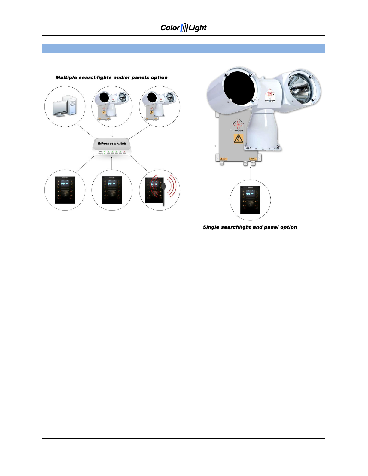
2. COLORLIGHT SEARCHLIGHT SYSTEM
ColorLight has with its newly developed control system for searchlights opened for a flexible and
future-proof system in which several searchlight assemblies (CL20, CL25 and CL35) and
operator panels can be connected to a dedicated network and communicate via the Ethernet
protocol.
Control-computers and navigation equipment are other examples of devices that can be part of
this network.
For external communication between the electrical box and its various controllers we use the
Ethernet protocol, but for internal communication between the box and searchlight we have
chosen to work with CAN bus technology.
CAN (Controller Area Network) is a network standard originally developed for the automotive
industry and with only two wires it‟s possible to transmit a variety of control data and
information.
The searchlights drive motors (horizontal and vertical) are of the type brushless servo motors,
with excellent performance, long lifetime and high reliability.
The motor drivers are located inside the searchlight and are of an "intelligent" type, which
constantly analyzes the motor condition, and if problems arise, such as tripped over current
protection; this will be presented as an alarm in the operator panel.
Page 6 User’s Manual
Page 7
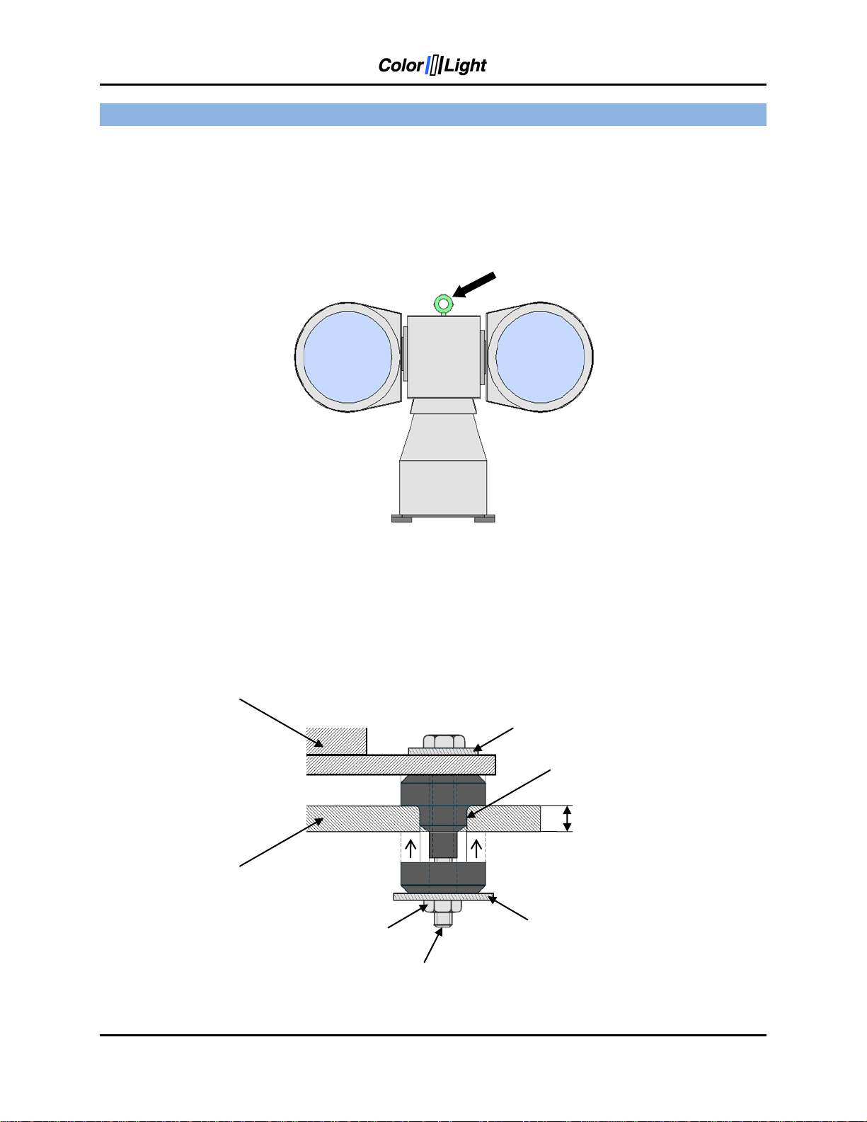
Bolt A4
M10x60
Washer A4
10,5x20x2
Searchlight
Mounting hole
Ø20mm
10mm
Foundation
Washer A4
10,5x30x2,5
Lock nut
A4 M10
Lift here!
3. INSTALLATION
3.1 Physical handling of the searchlight
Lift only the searchlight by the temporary lift loop on top of the center house. Lifting at the lamp
houses may damage the construction. After safely fixed the searchlight, remove the lift loop.
3.2 Mounting of the anti-vibration dampers
The picture shows how the dampers are mounted to avoid vibrations that can damage the
mechanics and shorten the life of the bulbs. Searchlight installation without dampers is not
recommended and this can, if problems arise, affect the warranty.
User’s Manual Page 7
Page 8
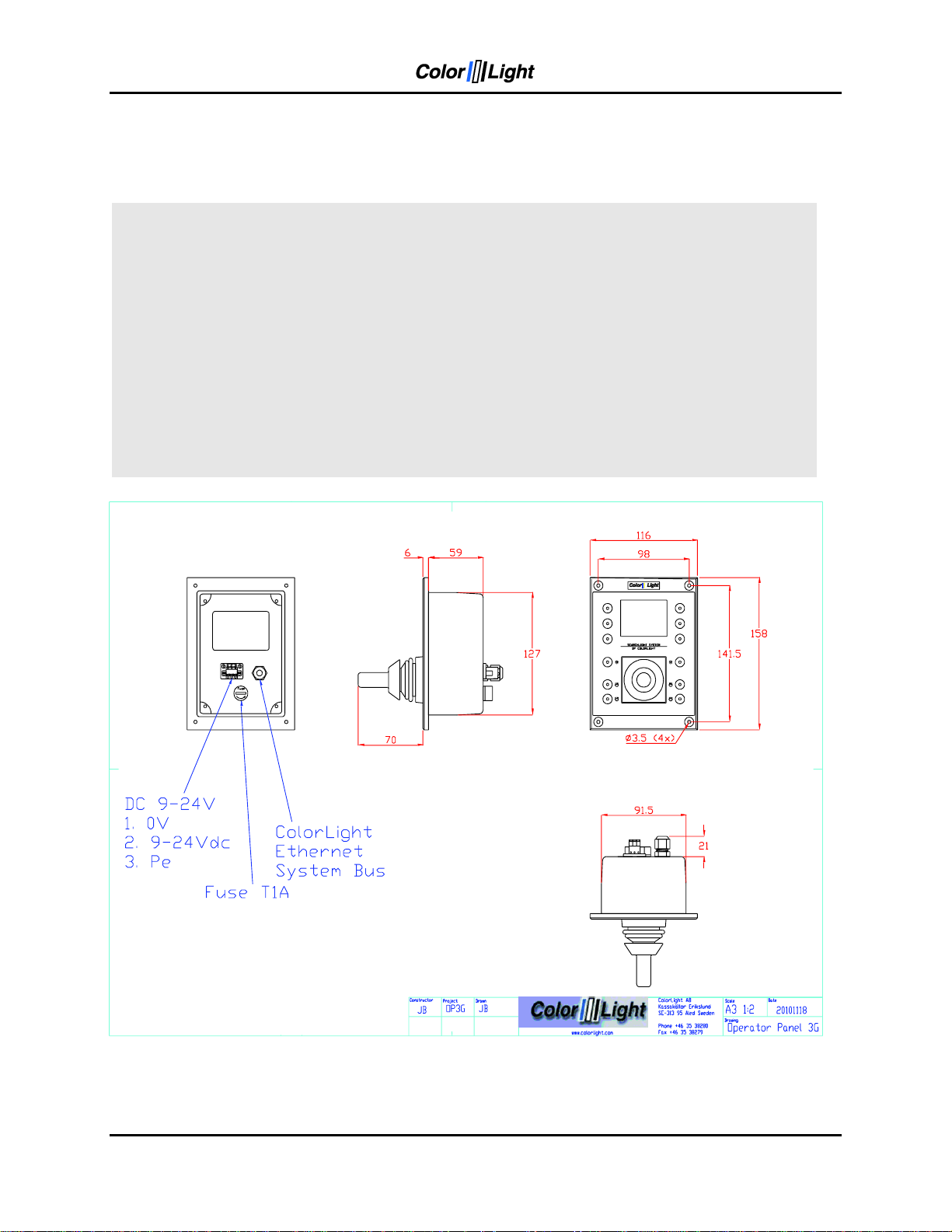
Operator Panel
User Interface
Size
See drawing "Operator Panel 3G"
Display
2.4” (240 xRGBx320)
Weight (kg)
0,55
Push buttons with led ilumination
12 pcs
Panel
Anodized Aluminum
Communication Protocol:
Ethernet
Enclosure
ABS 2mm
Environment
Gasket (optional)
EPDM
Operational temperature
*******************
Overlay
Polyester membrane switch
Storage temperature
*******************
Power Supply
Humidity (non-condensing)
*% RH
Input Voltage
9-24 V DC
Protection category
IP21 (standard), IP44 (option)
Current consumption
≈ 150 mA/24V
Fuse (5x20mm)
T1A
External PSU (optional)
Type
Phoenix STEP-PS 2868635
Input Voltage
100-240V AC (50-60Hz)
Output Voltage
24V DC (750 mA)
3.3 Specifications and drawings
3.3.1 Operator Panel
Page 8 User’s Manual
Page 9
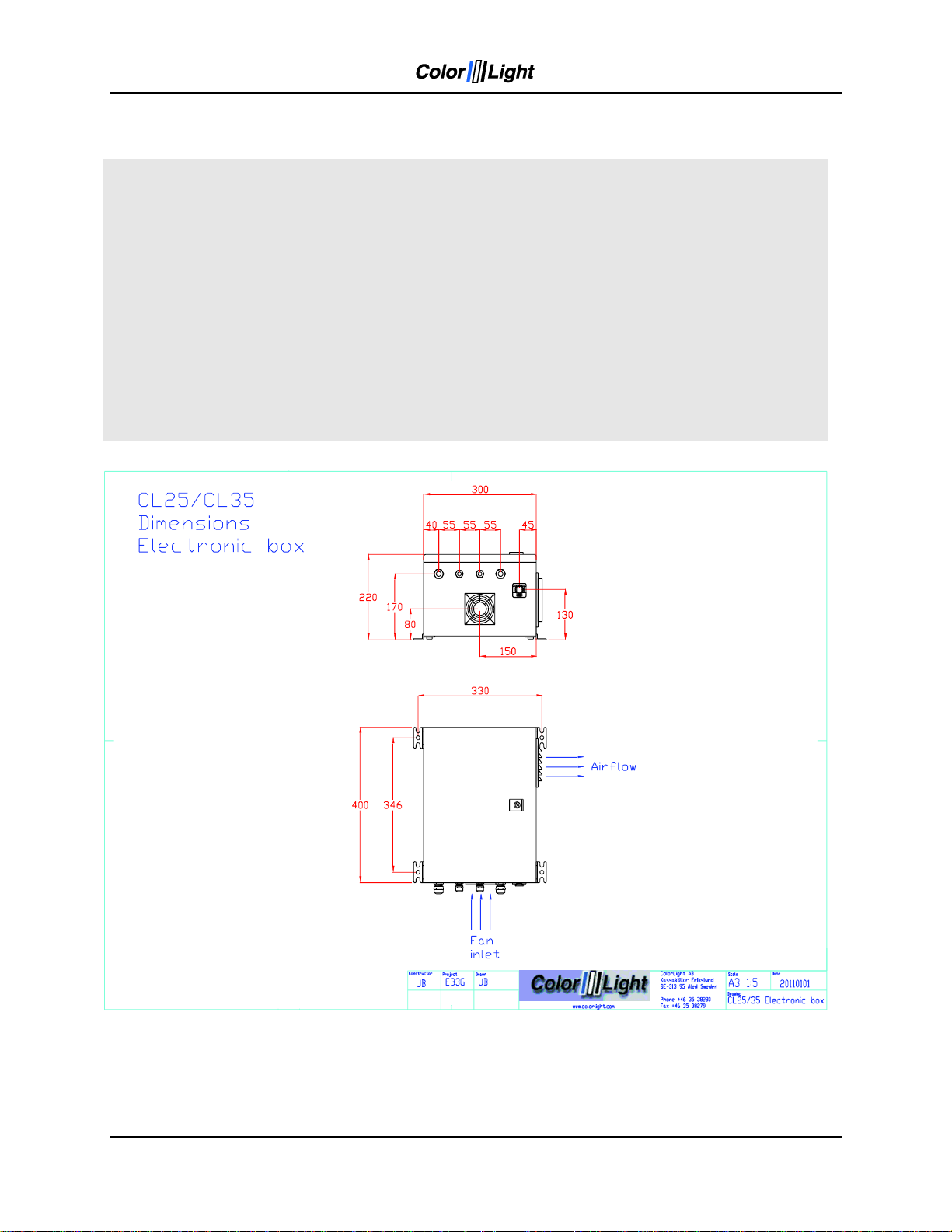
Box details
User Interface
Size
See drawing "CL25/35 Electronic box"
Display
2.4” (240 xRGBx320)
Weight (kg)
15
Push buttons with led ilumination
12 pcs
Material
Steel
Communication Protocol:
Ethernet OP / CAN searchlight
Color
RAL 7035 powder-coated
Environment
Cooling
Fan 80mm
Operational temperature
-40º C till +50º C
Overlay
Polyester membrane switch
Storage temperature
-10º C till +70º C
Power Supply
Humidity (non-condensing)
90% RH
Input Voltage
100-240 V AC
Protection category
IP44
Current consumption
≈ 150 mA/24V
Fuse (5x20mm)
T1A
External PSU (optional)
Type
Phoenix STEP-PS 2868635
Input Voltage
100-240V AC (50-60Hz)
Output Voltage
24V DC (750 mA)
3.3.3 Electrical box
User’s Manual Page 9
Page 10
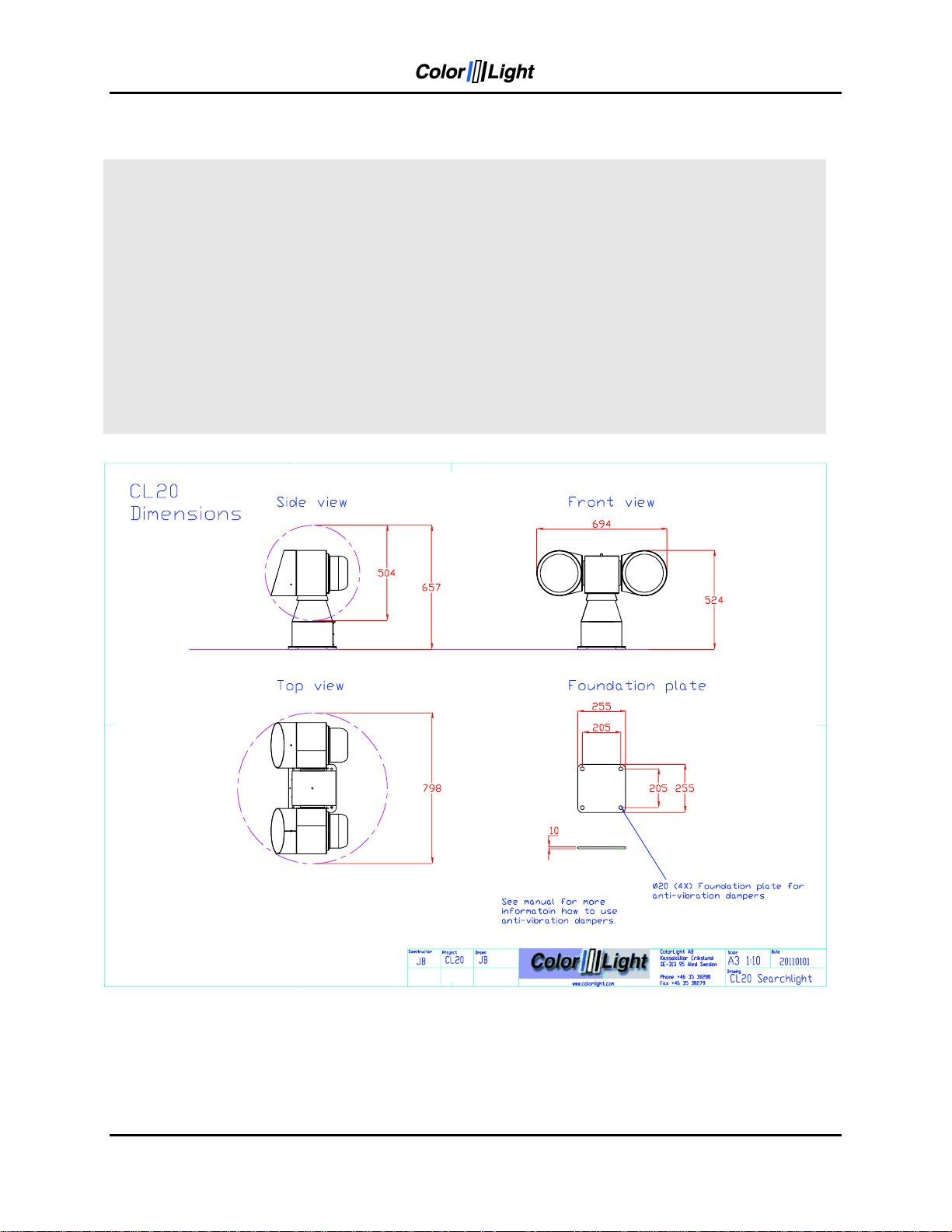
Operator Panel
User Interface
Size
See drawing "CL20 Searchlight"
Display
2.4” (240 xRGBx320)
Weight (kg)
0,55
Push buttons with led ilumination
12 pcs
Panel
Anodized Aluminum
Communication Protocol:
Ethernet
Enclosure
ABS 2mm
Environment
Gasket (optional)
EPDM
Operational temperature
-40º C till +50º C
Overlay
Polyester membrane switch
Storage temperature
-10º C till +70º C
Power Supply
Humidity (non-condensing)
90% RH
Input Voltage
9-24 V DC
Protection category
IP44
Current consumption
≈ 150 mA/24V
Fuse (5x20mm)
T1A
External PSU (optional)
Type
Phoenix STEP-PS 2868635
Input Voltage
100-240V AC (50-60Hz)
Output Voltage
24V DC (750 mA)
3.3.4 CL20
Page 10 User’s Manual
Page 11
Operator Panel
User Interface
Size
See drawing "Operator Panel 3G"
Display
2.4” (240 xRGBx320)
Weight (kg)
0,55
Push buttons with led ilumination
12 pcs
Panel
Anodized Aluminum
Communication Protocol:
Ethernet
Enclosure
ABS 2mm
Environment
Gasket (optional)
EPDM
Operational temperature
-40º C till +50º C
Overlay
Polyester membrane switch
Storage temperature
-10º C till +70º C
Power Supply
Humidity (non-condensing)
90% RH
Input Voltage
9-24 V DC
Protection category
IP44
Current consumption
≈ 150 mA/24V
Fuse (5x20mm)
T1A
External PSU (optional)
Type
Phoenix STEP-PS 2868635
Input Voltage
100-240V AC (50-60Hz)
Output Voltage
24V DC (750 mA)
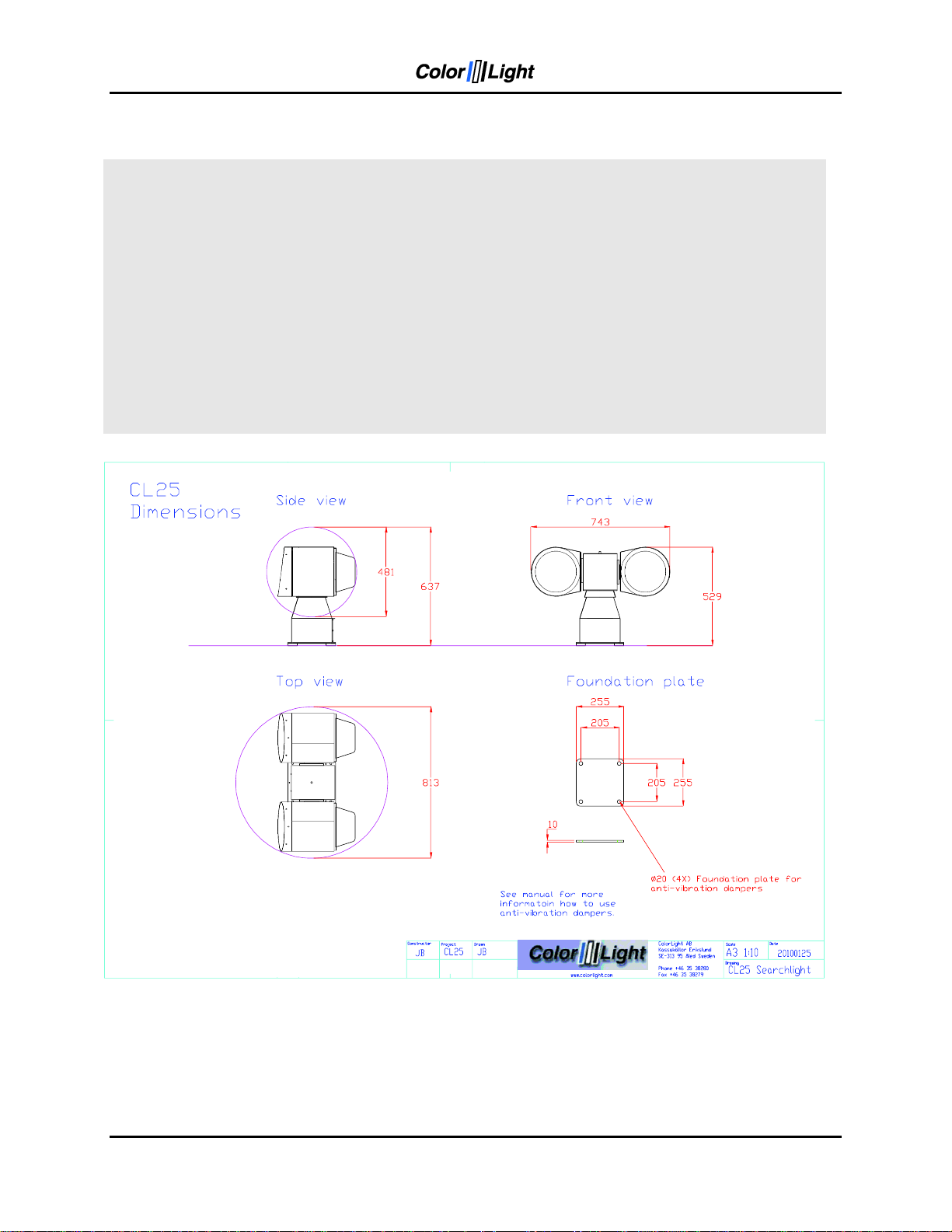
3.3.5 CL25
The searchlights cable glands are rated IP68 but for extra protection during heavy weather
situations it‟s still recommendable to install the searchlight so the cable exits are facing the
stern.
The longer part of the lamp house peak shall be set down. This extra long peak is to reduce
disturbing reflections from the foredeck, if any.
User’s Manual Page 11
Page 12
Operator Panel
User Interface
Size
See drawing "Operator Panel 3G"
Display
2.4” (240 xRGBx320)
Weight (kg)
0,55
Push buttons with led ilumination
12 pcs
Panel
Anodized Aluminum
Communication Protocol:
Ethernet
Enclosure
ABS 2mm
Environment
Gasket (optional)
EPDM
Operational temperature
-40º C till +50º C
Overlay
Polyester membrane switch
Storage temperature
-10º C till +70º C
Power Supply
Humidity (non-condensing)
90% RH
Input Voltage
9-24 V DC
Protection category
IP44
Current consumption
≈ 150 mA/24V
Fuse (5x20mm)
T1A
External PSU (optional)
Type
Phoenix STEP-PS 2868635
Input Voltage
100-240V AC (50-60Hz)
Output Voltage
24V DC (750 mA)
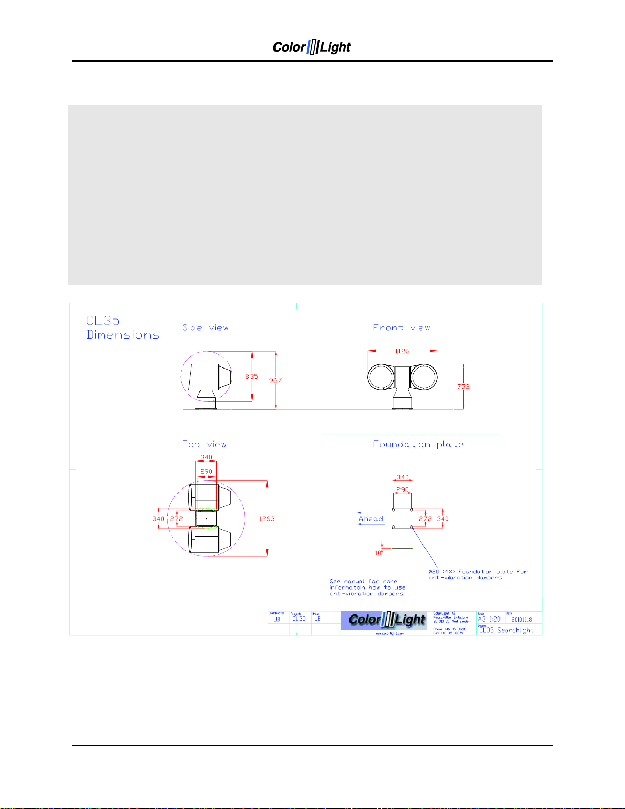
3.3.6 CL35
The searchlights cable glands are rated IP68 but for extra protection during heavy weather
situations it‟s still recommendable to install the searchlight so the cable exits are facing the
stern.
The longer part of the lamp house peak shall be set down. This extra long peak is to reduce
disturbing reflections from the foredeck, if any.
Page 12 User’s Manual
Page 13
9
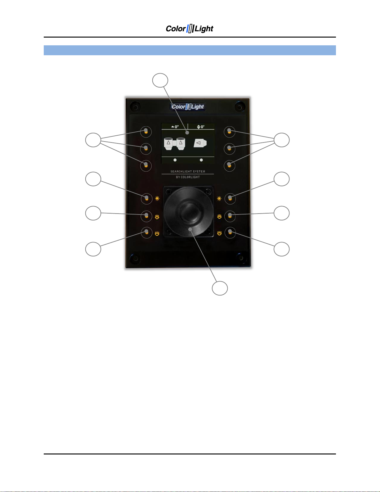
Figure 1: The operating panel.
4. OPERATOR PANEL, OVERVIEW.
1. "Soft button": the function appears in the display window next to the button.
2. Left lamp on / off.
3. Left focus (the same function as No. 4).
4. Left focus (the same function as No. 3).
5. Right lamp on / off.
6. Right focus (the same function as No 7).
7. Right focus (the same function as No 6).
8. Joystick.
9. Display.
Several sections of the manual refers to the above figures.
User’s Manual Page 13
Page 14
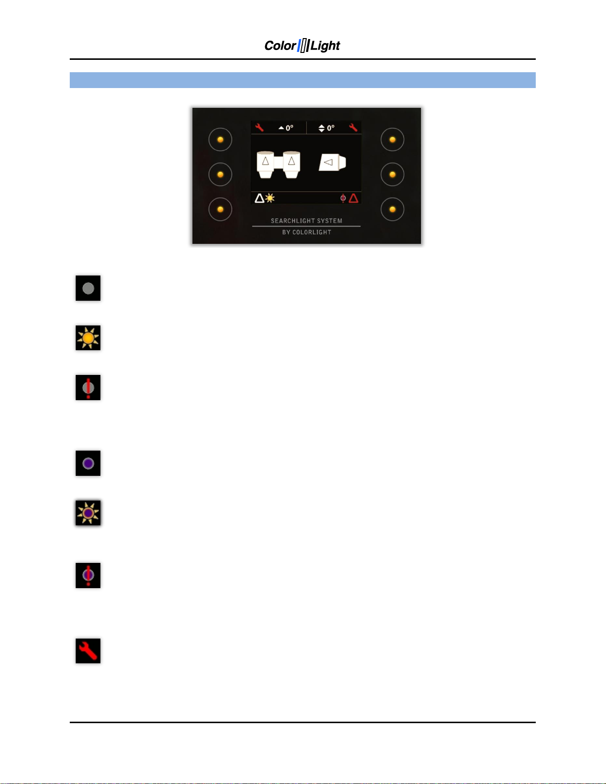
5. DISPLAY SYMBOLS AND MESSAGES
Symbol for switched of white light.
Symbol for switched on white light.
Error symbol for white light indicates a problem during switch on or if the bulb
breaks down during operation. The operator has three switch-on attempts in a two
minute interval without setting the sum alarm output. This symbol is only valid for
CL25 and CL35 (CL20 does not have this feature).
Symbol for switched of UV light (black light). Only valid for CL25 and CL35 (CL20
does not have this feature).
Symbol for switched on UV light. Only valid for CL25 and CL35 (CL20 does not
have this feature).
Error symbol for UV light indicates a problem during switch on or if the bulb breaks
down during operation. The operator has three switch-on attempts in a two minute
interval without setting the sum alarm output. This symbol is only valid for CL25
and CL35 (CL20 does not have this feature).
Symbol for any electro-mechanic error. Might be referred as an over voltage or
over current for motor drivers. Communication error with motor drivers will result in
the same symbol. This error symbol can be reset by simply enter the main menu
and select status. Then press “dismiss”. If over current have occurred the problem
might be referred as a stucked lamp housing – check for any icing issues. Each
axis has its own symbol showing in upper left or right corner of the display.
Page 14 User’s Manual
Page 15
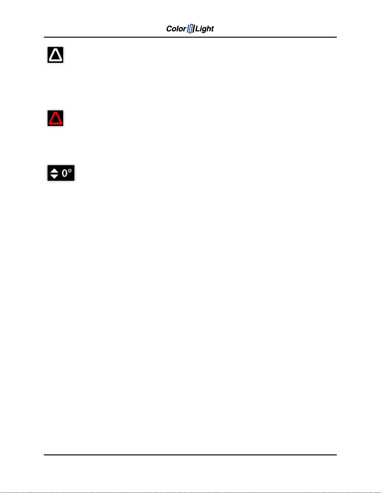
This symbol indicates that the bulb has less than 200 hours left of expected
lifetime. This warning can be chosen by the operator to be shown or not. Please
see 11.8.4 Lamp life for more detailed instruction.
Each bulb has its own symbol showing in the lower left or right corner of the
display.
This symbol indicates that the expected lifetime of the bulb now has expired. The
only way to reset this symbol is by entering the “Usage Stats” menu at the
diagnostic display inside the electrical box. See 12.4 Category 3: Usage Stats
Certainly this reset should only be done together with a bulb replacement!
This symbol and a similar symbol indicate the direction of the lamp housing both
for the vertical axis and for the horizontal axis. The arrows in the shown symbol
indicate the elevation angle for the vertical axis according to the horizontal-plane.
For the horizontal symbol and axis these small arrows indicate if the housing is
directed to the left, front, right or back of the centerline.
If the arrows are replaced by question marks then the system needs to be
internally calibrated. This is the normal state after power up after a total power loss
to the system. The easiest way to do the internal calibration is by simply choose
the “Park” in the quick start menu, please see 10.5 Off and park.
User’s Manual Page 15
Page 16

6. ACTIONS AFTER INSTALLATION OR POWER FAILURE
At the first boot after installation or power failure, the searchlight must be synchronized with the
control system.
After installation or power failure of the electric box you can use the searchlights main functions
like joystick control, light on/off and focus but in order to be able to use positioning functions
such as display indicator*, parking position, sweep*, fixed positions* or surveillance*, the
searchlight must be synchronized with the control system.
The easiest way to synchronize the system is to enter the quick start menu and select the “Park”
function. Now the searchlight will synchronize and then park if a parking position has been set.
If necessary the origin can be set after the steps above to give an accurate readout of the
indicator*. To set the origin please see 11.8.6.1 Store origin.
*Optional function.
Page 16 User’s Manual
Page 17

7. STARTING SYSTEM
When the system is in sleep the buttons and symbols glows with orange light and the display is
totally shut down to save power. Buttons and symbols are always active but dimmed to a lower
intensity during sleep.
Pressing any button on the operator panel will activate the system and the display will now show
the indicator* image or just the ColorLight logotype. Buttons and symbols are now brighter and
both buttons, symbols and display intensity can be adjusted, please see
11.8.1 Backlight brightness.
*Optional function
User’s Manual Page 17
Page 18

8. JOYSTICK FUNCTIONS
The joystick (8) moves the searchlight horizontally and vertically. There are no limitations to the
movement of the searchlight thanks to the slip ring technology developed by ColorLight.
The more the joystick is moved to its end position the faster the searchlight rotates*.
Searchlight rotation speed can be set, see 11.8.5 Maximum rotation speed.
The vertical axis reaction according to the joysticks movement can be reversed if decided by
operator. To change this reaction please see 11.8.3 Joystick direction.
The joystick can also be used to navigate in menus containing more than one choice.
Move the joystick up or down to navigate in the menu. In most menus joystick moved to the right
will act as “OK” button and moved to the left will go back one step as the “Back” button.
*Optional function
Page 18 User’s Manual
Page 19

9. SWITCH ON LIGHT
The searchlight is equipped with two bulbs which can be turned on / off separately by pressing
(3) to turn on the left light and (6) to turn on the right light. To turn off the light just press the
same button again.
In the bottom part of the display there are two sun-symbols that indicates the status of each
bulb.
CL25 and CL35
If the system is unable to switch on the bulbs there will be a red exclamation mark over the sunsymbol for the no working bulb. This error might occur if the operator decides to switch on a
bulb that recently has been shut off without any time to cool down before the next switch on.
Normally wait a few seconds (the longer the better) and try again. The system accepts three
turn on attempts (initiated by the operator) in a two minute time interval before the sum-alarm is
activated.
If the bulb breaks during operation the sum-alarm will be activated directly. The error symbol
with the exclamation mark over the sun-symbol will show again in the display over the
corresponding bulb.
There is a bulb warning feature in the system. This warning can be chosen by the operator to be
shown or not by switch on or off the function in the settings menu, please see 11.8.4 Lamp life.
This warning feature will show a white triangle symbol when the estimated bulb life left is less
than 200 hours. The symbol will be shown at the displays bottom left or right corner according to
left or right bulb.
When the expected lifetime is expired the white triangle will change to a red triangle. The only
way to reset this symbol is by entering the “lamp life” menu at the diagnostic display inside the
electrical box. To get to the correct menu use the three buttons below the display. Under the lamp
life menu there are two choices: usage statistics and reset counters. Select reset counters and
select the corresponding lamp housing for which the counter should be reset. Certainly this reset
should only be done together with a bulb replacement!
User’s Manual Page 19
Page 20

10. FOCUS
Pressing the focus buttons (3) or (4) changes the focus for the left lamp house and buttons (6)
or (7) changes focus for the right lamp house.
As long as a focus button is pressed the bulb moves in and out which changes the focus of the
light.
Release the button when the required focus is found.
Note, pressing (3) and (6) or (4) and (7) at the same time will cause an electric collision which
stops the focus from changing. Releasing one of the buttons will continue the focusing of the
pressed button. To focus with both lights simultaneously hold (3) and (7) or (4) and (6).
Page 20 User’s Manual
Page 21

11. QUICK START MENU
The operator panel features a quick start menu where you can reach some of the searchlights
functions.
To open up the quick start menu press any of the quick start menu buttons (1) when showing
the logo or indicator page. The quick start menu will close after 5 seconds.
11.1 Fixed positions (optional function)
Fixed position is an option for the ColorLight Searchlight System and can only be accessed if
activated.
There are up to four different programmable fixed positions in ColorLights Searchlight System.
11.1.1 Go to fixed position
To enter the "Fixed Light Position" submenu, open up the quick start menu and press the upper
left button "Positions".
There are up to four programmable fixed positions that can be programmed, A, B, C and D.
By selecting one of the positions the menu will change and show the current direction of the
searchlight in degrees and move the searchlight to the preprogrammed position automatically.
User’s Manual Page 21
Page 22

11.1.2 Store fixed position
If no position has been stored or the searchlight is at the stored position then the searchlight will
not move.
To store a new or change a fixed position, enter one of the fixed positions in the menu. If there
is a preprogrammed fixed position the searchlight will start to move to that position. To take
control over the searchlight just move the joystick to abort the movement of the searchlight. Now
move the searchlight by using the joystick to the desired position and press “Store”.
The current position is now stored.
Page 22 User’s Manual
Page 23

11.2 Sweep (optional function)
Sweep is an option for the ColorLight Searchlight System and can only be accessed if activated.
A sweep is where the searchlight automatically moves back and forth in the horizontal plane.
11.2.1 New Sweep
To enter the "Sweep" submenu, open up the quick start menu and press the left middle button
"Sweep".
To start a new sweep, navigate down to “New” in the “Sweep” menu and press “OK”.
The default setting for a sweep is a horizontal sweep of 20°.
To stop a sweep enter the "Sweep" submenu and choose “Stop” or just move the searchlight by
using the joystick.
To resume the sweep enter the "Sweep" submenu and choose “resume”.
User’s Manual Page 23
Page 24

11.2.2 Modify sweep parameters
To modify the sweep angle and / or the center of the sweep enter the “Sweep” menu and
navigate down to “Modify”, press OK.
In this menu changes to the sweep angle and center of the sweep can be modified in both
runtime and stand still.
To change the center line of the horizontal sweep move the joystick to the left or right until the
desired center is reached.
To change size of the sweep angle move the joystick up or down.
Press OK to save and update the searchlight with the new values.
Page 24 User’s Manual
Page 25

The default speed of the sweep is set to 50% of the maximum speed of the searchlight. To
change the speed of the sweep enter the “Sweep” menu and navigate down to “Speed”. Press
“OK” to enter the “Speed” submenu.
To change the speed move the joystick up or down to desired speed, press “OK” to update the
searchlight with the new speed.
Note: If the speed is updated during runtime then the speed will update when the searchlight
reaches its next end point.
User’s Manual Page 25
Page 26

11.3 Surveillance (optional function)
Surveillance is an option for the ColorLight Searchlight System and can only be accessed if
activated.
Surveillance is an advanced sweep where up to five points any ware can be set to be
surveillanced.
11.3.1 Setting a new surveillance sweep
To set a new surveillance sweep the number of positions must first be set.
To enter the “Surveillance” submenu, open up the quick start menu and press the bottom left
button.
Navigate down to “Number of Positions to Use” and press “OK”.
Page 26 User’s Manual
Page 27

In this menu you can choose from two to five positions to be used in a surveillance sweep.
Press “OK” to save and exit back to the “Surveillance” submenu.
There are five positions that can be programmed in a surveillance sweep.
To set the positions in a surveillance sweep enter the “Positions” menu in the “Surveillance”
submenu.
The surveillance sweep will start from position one and then go to position two and so on until
the searchlight has come to the number set in “Number of Positions to Use”.
To set a position enter the desired position then move the searchlight by using the joystick to
desired position. Press “Store” to store the position.
User’s Manual Page 27
Page 28

After pressing “Store” a new menu will appear, Pause Length. This is how long the searchlight
will stay at this position until starting to move to the next position. Pause length can be set
between zero and ten seconds.
Repeat this for the desired number of positions wanted in a surveillance sweep.
When done go back to the “Surveillance” submenu by pressing “Back”. Navigate to “Start” and
press “OK” to start the surveillance sweep.
11.3.2 Changing surveillance settings
Surveillance has a couple of different settings, “Loop Mode” and “Speed”.
In “Loop Mode” there are two choices, “Back and Forth” and “Repeat”.
When using “Back and Forth” the surveillance sweep will go from position one to two and so on
until it comes to the number set in “Number of Positions to Use” then it will go back to the
previous position.
When using “Repeat” the surveillance sweep will go from position one to two and so on until it
comes to the number set in “Number of Positions to Use” then it will go to position one instead
of going to the previous position.
To set “Back and Forth” or “Repeat” enter the “Surveillance” submenu then “Loop Mode”.
Page 28 User’s Manual
Page 29

Navigate to the preferred setting and press “OK” to save the setting and return to the
“Surveillance” menu.
“Speed” is where the speed of the rotation of the searchlight is set. Default setting is 50% of
maximum speed of the searchlight.
To change the speed of the surveillance sweep enter the “Surveillance” submenu then “Speed”.
Change the speed by moving the joystick up or down in the speed menu. The speed can be set
between 5-100% of the maximum rotation speed.
Note: If the speed is updated during runtime then the speed will update when the searchlight
reaches its next surveillance position.
User’s Manual Page 29
Page 30

11.4 Switch
If there are more than one ColorLight Searchlight in the system any operating panel can control
any of the connected ColorLight searchlights. Every searchlight should be given a unique name
during installation for this to work properly.
To enter the “Switch” submenu open up the quick start menu and press the upper right button.
In this menu all the available searchlights should be listed. To change which searchlight being
controlled, navigate to the desired searchlight and press “OK”.
The operating panel should now control the newly selected searchlight which is shown on the
indicator page.
Page 30 User’s Manual
Page 31

11.5 Off and park
By pressing the "Park" any lighted lamp will be turned off and the searchlight will automatically
look up the preprogrammed parking position, during this time you'll see
"Parking ..." in the bottom middle of the display.
When parked the operator panel will turn off the display after a few seconds and the LEDs
behind the buttons will be dimmed to a lower intensity.
User’s Manual Page 31
Page 32

12. MAIN MENU
From the quick start menu, select "Menu" to enter the system's main menu.
To navigate the main menu, use the joystick; push the joystick forward/up once to go up a step
in the menu and backwards/down to go down one step. Keep holding the joystick up or down
will scroll up and down in menus with “autorepeat”.
To confirm your choice use "OK" button and to leave the displayed menu, use the button
"Back". In many menus the joystick can be used as the “OK” button if moved to the right and as
the “Back” button if moved to the left.
12.1 Off and Park
Please see 10.5 Off and park for information regarding this menu choice.
12.2 Switch system
Please see 10.4 Switch for information regarding this menu choice.
12.3 Light Position
Please see 10.1 Fixed positions for information regarding this menu choice.
12.4 Sweep
Please see 10.2 Sweep for information regarding this menu choice.
12.5 Surveillance
Please see 10.3 Surveillance for information regarding this menu choice.
Page 32 User’s Manual
Page 33

12.6 Info
This menu shows information that is very useful to have handy during support from ColorLight if
any problems occur or any options should be added to the operator panel after purchase (more
about this later under 11.8.6.5 Options setup.
12.7 Status
This menu will give information of any errors in the system and bulb life counters. Some errors
can be reset from this menu by simply press the button marked “Dismiss”.
12.8 Settings
This opens a new menu with six sub menus.
12.8.1 Backlight brightness
Here can the displays brightness and button-LEDs intensity be adjusted by the operator.
BILD
User’s Manual Page 33
Page 34

12.8.2 Language (optional function)
The language in the display can be changed depending on which language sets that are
installed in the operator panel. This is an option and different sets of languages can be installed
from ColorLight at delivery. This is an option changing upon customer demands and requests,
please feel free to call ColorLight to see which different sets that are available.
12.8.3 Joystick direction
Some operators want to have their joystick to move the lamp housing vertically in the same
direction as the joysticks physical direction:
(joystick up=lamp housing moving upwards), this is called “Inverted” in the menu.
Normally the joystick acts like an aeroplane joystick:
(joystick up=lamp housing moving downwards), this is called “Normal” in the menu.
Page 34 User’s Manual
Page 35

12.8.4 Lamp life
In this menu there are two sub menus, Lamp life statistics and Lamp life warning.
Lamp life statistics menu will show a display similar to the status display in 11.7 Status.
The only difference is that no errors will be presented in this display.
Lamp life warning menu will make it possible for the operator to chose if the lamp life warning
feature should be activated or not. See 8 SWITCH ON LIGHT. The warning is normally enabled
when system is shipped from ColorLight.
User’s Manual Page 35
Page 36

12.8.5 Maximum rotation speed
This menu gives the operator the opportunity to set the maximum rotationspeed of the system.
Use the joystick to increase or decrease the speed by moving the joystick up or down.
Don‟t forget to make an “OK” button push or move the joystick to the right to having the change
to take effect in the system.
Page 36 User’s Manual
Page 37

12.8.6 Installation
In this menu there are five sub menus each described below:
12.8.6.1 Store origin
This menu is used to calibrate the systems indicator* where the “ZERO” point are set for both
vertical and horizontal axis.
Before the “Store origin” command is stored it‟s necessary that the synchronization between
operator panel and electrical box is done properly. The easiest way to do the synchronization is
by just turn the system off with the “Park” command, please see 10.5 Off and park.
Start the system according to 6 STARTING SYSTEM (normal start). Now normally the position
of the lamp housings should be adjusted to be in level with horizontal plane and in direction
straight forward of the vessel and then the “Store origin” can be executed and stored in the right
way.
User’s Manual Page 37
Page 38

12.8.6.2 Store park position
This menu makes it possible to store a park position in any direction for the lamp housings when
the system is selected by the “Park” command.
Before changing the default park position it‟s necessary that the synchronization between
operator panel and electrical box is done properly. The easiest way to do the synchronization is
by just turn the system off with the “Park” command, please see 10.5 Off and park.
From the default logo screen or display indicator*-screen, move the searchlight to the new
desired park position and when satisfied select menu>settings>Installation and enter sub
menu “Store park position”.
Press “OK” to save the new park position and return to the default logo screen or display
indicator*-screen
ColorLight recommend that the park position should be approximately 70 degrees down for the
vertical axis relatively to the horizontal plane. This recommended parking position is the most
effective position to avoid sand, rain, snow etc. to hit the glass in front of the lamps.
Page 38 User’s Manual
Page 39

12.8.6.3 Name system
The dedicated ColorLight network can contain several searchlights and operator panels.
To make the whole network easy to navigate; each electrical box and its corresponding
searchlight can be named to a well known name for the operator.
The name is set by moving the joystick up and down to select correct character. To move to
next character in the name the joystick is moved to the right. Finish the name process and save
the name by select “OK” by pushing the button at the right bottom corner of the display.
User’s Manual Page 39
Page 40

12.8.6.4 Start test sequence
This menu starts a test sequence which tests the movement of the lamp housings and focus for
each lamp house one at a time.
The test sequence will perform as follows:
At test sequence startup the lamp housing will be moved to parking position.
The horizontal axis will be rotated a fully revolution clockwise.
The vertical axis will be rotated a fully revolution clockwise.
The left lamp houses focus motor is activated during 10seconds.
The right lamp houses focus motor is activated during 10secinds.
The whole sequence above will be repeated 5 times before the test sequence is automatically
abandoned. Every even time the rotation will be anti clockwise and every odd time the rotation
will be clockwise. During the test sequence the operator can switch on and off lights by simply
press the button 2 and 5 according to the figure in 3. OPERATOR PANEL, OVERVIEW. The
test sequence can‟t be abandoned by the operator without switching the main power off to the
electrical box.
Page 40 User’s Manual
Page 41

12.8.6.5 Options setup
This menu is used to install special “codes” to unlock and to get access to special functions.
The code is entered by moving the joystick up and down to select correct character. To move to
next character the joystick is moved to the right. Finish the process by select “OK” by pushing
the button at the right bottom corner of the display
The “codes” are individual for each operator panel. To get access to the “codes” the customer
needs to call ColorLight for quotation. ColorLight need the MAC address for the relevant
operator panel to be able to get the right code for their customer. Please see 11.6 Info.
The following options are available and can be directly accessed by entering a code:
Step less joystick speed control
Display indicator
Fixed positions, please see 10.6 Fixed positions
Sweep (auto sweep horizontal)
Surveillance
Language
User’s Manual Page 41
Page 42

1. About
1.1 MAC Address
1.2 IP Address
1.3 Light Model
1.4 SW Version
2. Diagnostics
2.1 Start
2.2 View Results
3. Usage Stats
3.1 Left Light
3.2 Right Light
3.3 Reset Left
3. 4 Reset Right
Right
Down
OK
13. CABINET CARD MENU SYSTEM
This chapter describes the menu system of the ColorLight Cabinet Card displayed on the onboard LCD.
13.1 Inputs
The user interacts with the menu system using the three buttons, the Down button, the Right
button and the OK button.
13.1.1 Down Button
The main function of the Down buttons is to shift between the menu categories. It also has two
alternate generic functions.
1. While in submenus listing items of various types the Down button scrolls down in the list.
2. While entering a value of some sort, the Down button decrements that value.
13.1.2 Right Button
The main function of the Right buttons is to shift between the submenus of the selected menu
category. It also has two alternate generic functions.
1. While in submenus listing items of various types the Right button scrolls up in the list.
2. While entering a value of some sort, the Right button increments that value.
13.1.3 OK Button
The OK button enters and exits submenus.
Page 42 User’s Manual
Page 43

13.2 Category 1: About
In this chapter all of Category 1 menu items will be explained.
13.2.1 1.1 MAC Address
Displays the MAC address of the Cabinet Card, according to the standard (IEEE 802) in six
groups of two hexadecimal digits, separated by colons („:‟), in transmission order, e.g.
“01:23:45:67:89:ab”. One exception from the standard is made, the leftmost colon is missing,
due to the 16 character limit of the LCD.
13.2.2 1.2 IP Address
Displays the IPv4 address of the Cabinet Card, in four groups of one to three decimal digits,
separated by dots („.‟), e.g. “169.254.17.5”.
13.2.3 1.3 Light Model
Displays the searchlight model that the Cabinet Card is configured to use, e.g. “Model: CL2512”.
13.2.4 1.4 SW Version
Displays the firmware version of the Cabinet Card, e.g. “0.1.2.3”.
User’s Manual Page 43
Page 44

13.3 Category 2: Diagnostics (support tool)
In this chapter all of Category 2 menu items will be explained.
13.3.1 2.1 Start
Press the OK button to run the on-board diagnostic test suite to sense the electrical and
mechanical condition of the searchlight. (contact Colorlight for help with this feature).
T1. Measurement of voltage and current when the searchlight is in “non operating mode”
T2 (HCW). Measurement of current drawn by the horizontal motor; motor rotates clockwise for
30 seconds.
T3 (HCCW). Measurement of current drawn by the horizontal motor; motor rotates
counterclockwise for 30 seconds.
T4 (VCW). Measurement of current drawn by the vertical motor; motor rotates clockwise for 30
seconds.
T5 (VCCW). Measurement of current drawn by the vertical motor; motor rotates
counterclockwise for 30 seconds and the value is temporary stored.
T6 (Rfoc). Measurement of current drawn by the right focus motor; runs for 30 seconds.
T7 (Lfoc). Measurement of current drawn by the left focus motor; runs for 30 seconds.
T8 (H MAG). Test of horizontal magnetic sensor; the horizontal motor is running at full speed for
a predetermined time and number of triggers is recorded.
T9 (V MAG). Test of vertical magnetic sensor; the vertical motor is running at full speed for a
predetermined time and number of triggers is recorded.
T10 (Lights). Lamp test; both lights should ignite and be lit for 30 seconds.
To avoid burning anything with the bright light the test is performed with both axis rotating in half
speed. The result is temporary stored.
13.3.2 2.2 View Results
Displays the result of the last run diagnostics test suite.
Use the Down button to cycle through the tests results.
Use the Right button to cycle through different test result information for the selected test. Only
applicable for test “T1” and test “T10”.
Page 44 User’s Manual
Page 45

13.4 Category 3: Usage Stats
In this chapter all of Category 3 menu items will be explained.
13.4.1 3.1 Left Light
Displays the usage of the left light source in hours:minutes:seconds, e.g. “Left: 1:23:45”.
13.4.2 3.2 Right Light
Displays the usage of the right light source in hours:minutes:seconds, e.g. “Right: 1:23:45”.
13.4.3 3.3 Reset Left
Resets the usage counter of the left light source.
A confirmation message, “If sure press OK”, is displayed upon entering the menu. Press the OK
button at this point to reset the counter and exit the menu. Press the Down or Right button to
exit the menu without resetting the counter.
13.4.4 3.4 Reset Right
Resets the usage counter of the right light source.
A confirmation message, “If sure press OK”, is displayed upon entering the menu. Press the OK
button at this point to reset the counter and exit the menu. Press the Down or Right button to
exit the menu without resetting the counter.
User’s Manual Page 45
Page 46

SN LABEL
Electronic box ID:
SN LABEL
OP/RADIO ID:
INFO LABEL
SW
LABEL 1
SW
LABEL 2
SW
LABEL 3
SN LABEL 1
Mac ID1 ___:___:___:___:___:___
SN LABEL 3
Mac ID3 ___:___:___:___:___:___
SN LABEL 2
Mac ID2 ___:___:___:___:___:___
System info verified by:
Name:______________________
Date: ______________________
System extras:
ETHERNET SWITCH LABEL
LABEL
14. SYSTEM IDENTIFICATION PAGE
On this page you can find information about your system as it was configured when it left
colorlight. In case of system support please mail us the components serialnumbers.
Remember to keep this page updated if adding or replacing components like operator panels.
Searchlight ID:
Page 46 User’s Manual
Page 47

15. SUPPORT
If you have questions about the searchlight and its features, please contact ColorLight technical
support worldwide, see www.colorlight.com for contact details.
Or contact ColorLight head office:
Color Light AB
Engineering-Color Light
cl@colorlight.com
Phone: +46 353 8270
Fax: +46 35 38279
If you want to upgrade your system with additional options (see 11.8.6.5), please contact:
ColorLight AB
Kassakällor Erikslund
SE-313 95 Åled
Sweden
Phone: +46 35 38280
Fax: +46 35 38279
www.colorlight.com
info@colorlight.com
Notes:
User’s Manual Page 47
 Loading...