

Page 1
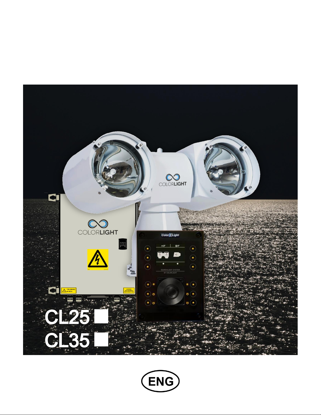
SEARCHLIGHT SYSTEM
BY COLORLIGHT
INSTALLATION MANUAL
Revision nr: F1.6
Revision date: 2014-04
Page 2

Safety reminder
Remember to break all electrical power to system before
starting any work in the electrical box or the searchlight
unit.
All information in this manual was correct at time of publication. However, as our engineers are
always updating and improving our products, your system's software might provide a slightly
different appearance or modified functionality than presented in this manual.
If your system lacks any function presented in this manual, there is possibly a software update
available to resolve this, please contact ColorLight for more information.
COPYRIGHT COLORLIGHT © 2014. All rights reserved
Page 2 INSTALLATION MANUAL CL25, CL35
Page 3

CONTENT
WARNINGS AND INFORMATION ..................................................................................... 5 1.
WARRANTY CONDITIONS ................................................................................................ 8 2.
MAINTENANCE AND SERVICE PLAN .............................................................................. 9 3.
COLORLIGHT SEARCHLIGHT SYSTEM .........................................................................10 4.
INSTALLATION .................................................................................................................11 5.
5.1 Physical handling of the searchlight .......................................................................11
CLI-30001, ANTI VIBRATION KIT.....................................................................................12
6.
CLI-30005, REPLACING THE BULB ................................................................................15 7.
ELECTRICAL SYSTEM .....................................................................................................21 8.
8.1 Electrical-box ............................................................................................................21
8.2 Cabinet card ..............................................................................................................22
8.3 Electrical-box overview ............................................................................................23
8.4 Electrical box installation .........................................................................................24
8.5 Operator panel connections.....................................................................................25
8.6 Ethernet wiring ................................ ................................................................ ..........26
OPERATOR PANEL, OVERVIEW.....................................................................................27 9.
DISPLAY SYMBOLS AND MESSAGES ........................................................................28 10.
10.1 Ebox alarm relay ................................................................................................ .......29
ACTIONS AFTER INSTALLATION OR POWER FAILURE ...........................................30 11.
STARTING SYSTEM .....................................................................................................31 12.
JOYSTICK FUNCTIONS ................................................................................................32 13.
SWITCH ON LIGHT .......................................................................................................33 14.
FOCUS...........................................................................................................................34 15.
15.1 Type 1, continuous focus (standard) .......................................................................34
15.2 Type 2, absolute focus (optional for CL25) .............................................................35
CABINET CARD MENU SYSTEM .................................................................................36 16.
16.1 Menu navigation........................................................................................................36
16.1.1 Down Button ........................................................................................................................ 36
16.1.2 Right Button ......................................................................................................................... 36
16.1.3 OK Button ............................................................................................................................ 36
16.2 Category 1: About .....................................................................................................37
16.2.1 (1.1) MAC Address .............................................................................................................. 37
16.2.2 (1.2) IP Address .................................................................................................................. 37
16.2.3 (1.3) Light Model ................................................................................................................. 37
16.2.4 (1.4) SW Version ................................................................................................................. 37
16.3 Category 2: Diagnostics (support tool) ...................................................................38
16.3.1 (2.1) Start ............................................................................................................................ 38
16.3.2 (2.2) View Results ............................................................................................................... 38
INSTALLATION MANUAL CL25, CL35 Page 3
Page 4

Approvals
written by:
Anders Holst
reviewed by:
Jonas Boslander
approved by:
Mattias Svensson
16.4 Category 3: Usage Stats ...........................................................................................39
16.4.1 (3.1) Left Light ..................................................................................................................... 39
16.4.2 (3.2) Right Light ................................................................................................................... 39
16.4.3 (3.3) Reset Left .................................................................................................................... 39
16.4.4 (3.4) Reset Right ................................................................................................................. 39
16.5 Category 4: Settings .................................................................................................40
16.5.1 (4.1) OP WDT ...................................................................................................................... 40
16.5.2 (4.2) OP WDT Stats ............................................................................................................ 41
16.5.3 (4.3) OP WDT Reset ........................................................................................................... 41
TECHNICAL DATA CL25 ................................................................ ..............................42 17.
17.1 Specifications CL25 ..................................................................................................42
17.2 Mechanical drawings ................................................................................................43
17.2.1 Operator Panel .................................................................................................................... 43
17.2.2 Electrical box ....................................................................................................................... 44
17.2.3 Searchlight CL25 ................................................................................................................. 45
TECHNICAL DATA CL35 ................................................................ ..............................46 18.
18.1 Specifications CL35 ..................................................................................................46
18.2 Mechanical drawings ................................................................................................47
18.2.1 Operator Panel .................................................................................................................... 47
18.2.2 Electrical box ....................................................................................................................... 48
18.2.3 Searchlight CL35 ................................................................................................................. 49
SUPPORT ................................ ......................................................................................50 19.
Page 4 INSTALLATION MANUAL CL25, CL35
Page 5
WARNINGS AND INFORMATION 1.
High voltage!
Before opening any part of the searchlight system, make sure all power is switched
off!
Bulbs
HID (High-intensity discharge) bulbs operate at a high internal pressure and high
temperature and should be handled with care.
Never bump, drop, apply excessive stress, or scratch the bulb. This could cause
the bulb to burst! Do not operate any bulbs with any traces of scratches, cracks, or
physical damage
Always transport the bulb in the provided protective case or cover until installation!
Save the protective case or cover and packaging materials (box) for bulbs that
have been used to their rated service life. Use the protective case when disposing
of the bulbs.
Always use safety glasses and body protection when installing or removing the
bulbs.
When changing bulbs be sure to not touch the surface of the bulbs with bare
fingers. If inadvertently touched with bare fingers it should be degreased
immediately with alcohol and a soft lint free cloth. Be sure to wipe dry the bulb
surface afterwards.
Never touch the bulb when it is on, or soon after it has been turned off, as it is hot
and will cause serious burns. Bulbs should be allowed to cool for a minimum of ten
(10) minutes after the light is turned off.
The light should never under any circumstances be turned on without frontglass.
INSTALLATION MANUAL CL25, CL35 Page 5
Page 6
UV-light! (models -12, -21, -22)
The UV-light used by ColorLight is chosen for most efficient result in marine
applications. The wavelengths are below 400 nanometers, thus not visible for the
human eye. An intensive radiation is generated from the high luminance of the
arch inside the bulb and should not be glared into from close distance.
Intentionally ColorLight is allowing a small leakage of white light making the beam
vaguely detectable in fog. Avoid quick switch on and switch off as it may shorten
the lifetime of the bulb. Allow a couple of minutes cool down period, if possible.
UV-light overheat
CL20, CL25 and CL35 searchlights are designed and built primarily for the marine
environment.
UV light generates a lot of heat and we use ambient air as a coolant for our lamp
body. For uses other than marine this must be taken into account so that sufficient
cooling is available or to adapt the operating time to prevent overheating damage
such as cracked UV glass.
Eye safe exposure time for UV
CL25-12/21, CL35-12/21: Max 2 minutes at 1 m. Max 4 minutes at 2 m. Max 9
minutes at 4 m. Max 65 minutes at 9 m.
CL25-22, CL35-22: Max 1 minute at 1 m. Max 2 minutes at 2 m. Max 4 minutes
at 4 m.
Max 30 minutes at 9 m.
Welding eye glasses are recommended if you for some reasons have to expose
your eyes longer periods at those close distances.
We see no reason for such exposure even at service activities. Sunglasses are
also good protection.
Reflectors
The parabolic reflectors developed by ColorLight have an extremely smooth
surface to focus the light in wide or narrow beam. Bare fingers should never touch
the reflector surface. If inadvertently touched, the reflector surface should
immediately be degreased with alcohol and a soft lint free cloth.
Page 6 INSTALLATION MANUAL CL25, CL35
Page 7
Light beam heat damage and Ethernet communications guard OP WDT
This searchlight is built for use on long distances and the high-intensity light from
the searchlight can, if set at a narrow beam, cause severe damage to surfaces
closer than 1 meter. To avoid that the searchlight is forgotten with the light on,
always use the feature “off and park” when not using the searchlight.
If however a hardware failure occurs that breaks the Ethernet communication
between the box and operator panel, a safety function will step in and
automatically turn off the light within 3 seconds, the OP WDT will also interrupt an
ongoing sweep or surveillance activity.
OP WDT is disabled by default, to enable see 16.5.1 (4.1) OP WDT.
If protection hoods are used over searchlight body the system main power switch
in the electric box should be off; this is a precaution to reduce the risk of fire if the
hoods are not removed before turning the lights on.
Cleaning
Never wash the searchlight with water under high pressure because this can
penetrate through the seals and cause damage to mechanical and electrical
components.
Do not use strong solvents such as thinner or acetone to clean the searchlight
body or the operator panel.
Deicing
Removal of ice should be done with caution. Physical violence can damage the
front glass or the searchlight driving mechanics. Instead turn on the lights and let
the heat melt the ice.
Recycling and disposal
HMI bulbs used for model CL25 and CL35 contains mercury and must be recycled
or disposed according to applicable local and national regulations.
INSTALLATION MANUAL CL25, CL35 Page 7
Page 8

WARRANTY CONDITIONS 2.
A correctly installed searchlight system from ColorLight requires no planned regular
maintenance or service during the first 10 years in operation (except changing the bulbs after
they are used up).
The “Maintenance and Service plan” describes how to keep the product in good condition.
The warranty is conditioned by below mentioned key points.
Before powering up the unit, make sure that:
Vibration dampers are mounted correctly according to user’s manual.
The mechanical fundament where the searchlight is placed is robust.
Warranty seal on the service hatch is unbroken.
Outgoing cable radius from the searchlight is smooth and not stressed.
All cables used for the installations are as per ColorLight’s specifications or as per
separate made agreement.
Signal cables are not placed together with high power cables.
Electrical connections are made according to electrical scheme and wiring diagram.
Length of cables are not exceeding the recommended maximum lengths as stated
below:
Power cables between searchlight and E-box for 230 VAC-system: Max 30 meter
Power cables between searchlight and E-box for 24 VDC-system: Max 5 meter
Remote cable / Ethernet cable between E-box and remote control: Max 100 meter
(longer distance requires an amplifier or fibre optic version).
E-box (EB) is placed in an non-condense environment with a minimum temperature of
+5 C (indoor) if not customised for other installation.
The remote panel (OP) is bridge mounted in an IP54 environment. If placed outside it
must be under a protection hood when not in use.
Remote panel is screwed in bridge panel, properly grounded and correct installed.
After above checkpoints are verified the system should be started up as per User’s
Manual to verify the functionalities.
In case of any questions related to the warranty, please contact us at info@colorlight.com for
additional support.
Page 8 INSTALLATION MANUAL CL25, CL35
Page 9

MAINTENANCE AND SERVICE PLAN 3.
Although the system does not require regular maintenance to function, we recommend,
however, that this preventive maintenance plan is followed in order to keep the searchlight in
good condition and in time detect if something is wrong and needs to be corrected.
Recommended inspection on a weekly basis
1. Make visual inspection of the searchlight housing and cabling. Look for any potential
mechanical damage caused by external force. A damage can lead to reduced or nonfunctionality.
2. Make a visual inspection of the searchlight glasses. Verify that they are without any
crack or broken in any way. A crack can lead to water penetration inside the housing
followed by potential electrical and mechanical problem.
3. Perform a function test. Start up the searchlight system, rotate the searchlight in
horizontal and vertical direction. Check the “lamp life” statistics in order to plan any
potential replacement of bulb. The system is programmed to give a warning when there
is less than 130h of lamp bulb lifetime remaining.
4. Clean the searchlight. Rinse with fresh water to wash away the salt deposits. If more
dirty, use a very soft sponge and soap that is not caustic, contains strong solvents such
as acetone or thinner base. The house can be both polished and waxed for a shiny and
durable surface, but the glass should under no circumstances be waxed. Under no
circumstances can the searchlights be washed with high pressure water as this can lead
to penetration inside the housing followed by potential electrical and mechanical
problem.
5. Deicing. Winter time the system should be deiced with caution. First turn the lights on to
let the heat melt the ice before operating the system horizontally and vertically.
INSTALLATION MANUAL CL25, CL35 Page 9
Page 10
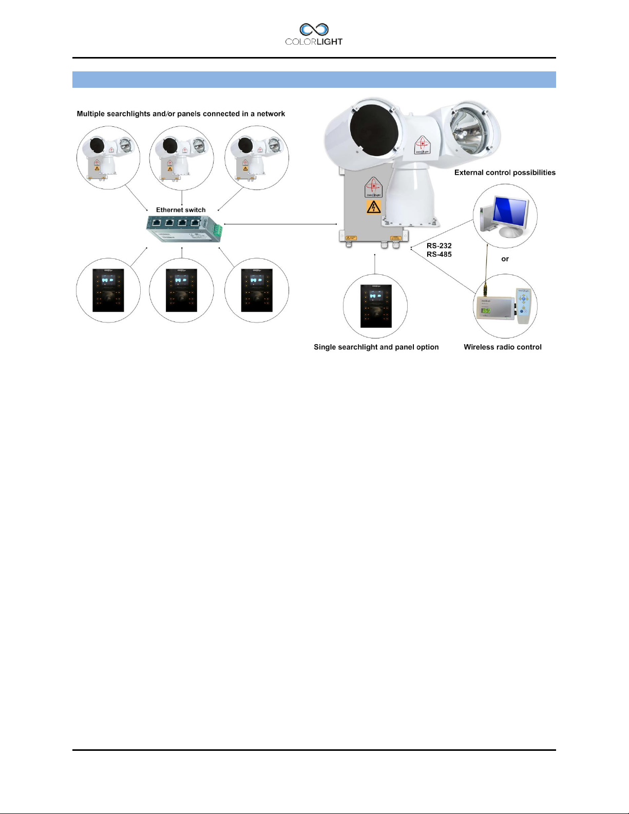
COLORLIGHT SEARCHLIGHT SYSTEM 4.
ColorLight has with its newly developed control system for searchlights opened for a flexible and
future-proof system in which several searchlight assemblies (CL20, CL25 and CL35) and
operator panels can be connected to a dedicated network and communicate via the Ethernet
protocol.
Control-computers and navigation equipment are other examples of devices that can be part of
this network.
For external communication between the electrical box and its various controllers we use the
TCP / IP protocol through the Ethernet infrastructure, but for internal communication between
the box and searchlight we have chosen to work with CAN bus technology.
CAN (Controller Area Network) is a network standard originally developed for the automotive
industry and with only two wires it’s possible to transmit a variety of control data and
information.
The searchlights drive motors (horizontal and vertical) are of the type brushless servo motors,
with excellent performance, long lifetime and high reliability.
The motor drivers are located inside the searchlight and are of an "intelligent" type, which
constantly analyzes the motor condition, and if problems arise, such as tripped over current
protection; this will be presented as an alarm in the operator panel.
Page 10 INSTALLATION MANUAL CL25, CL35
Page 11
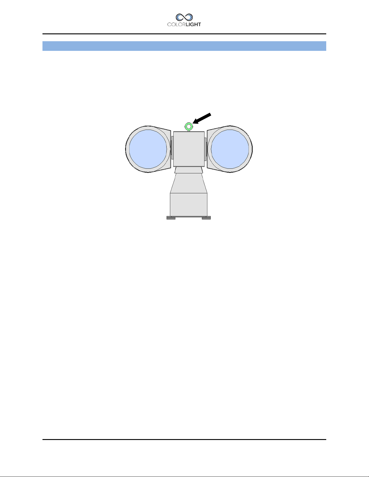
Lift here!
INSTALLATION 5.
Physical handling of the searchlight 5.1
Lift only the searchlight by the temporary lift loop on top of the center house. Lifting at the lamp
houses may damage the construction. After safely fixed the searchlight, remove the lift loop.
INSTALLATION MANUAL CL25, CL35 Page 11
Page 12
1
2
1
17mm ratchet wrench × 1
2
17mm wrench × 1
3
4
CLI-30001, ANTI VIBRATION KIT 6.
Service instruction no: CLI-30001
Revision date: 2012-12-19
Applicable models: CL25-**, CL35-**
Spareparts needed (refer to CL spareparts list)
Tools and supplies required:
Important information
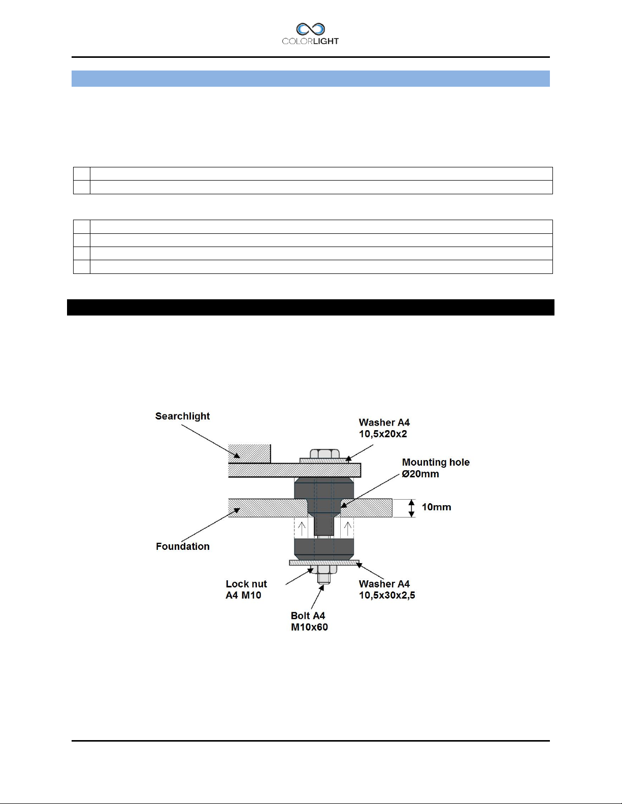
This instruction shows how to install the anti-vibration kit which consists of four dampers with
integrated stainless steel tubes.
The dampers main function is to absorb the harmful vibrations that can damage the mechanics
and shorten the life of the bulbs. Searchlight installations without dampers will
uncompromisingly, void the warranty.
Figure 1
1. Overview of the damper assembly and its parts.
Page 12 INSTALLATION MANUAL CL25, CL35
Page 13
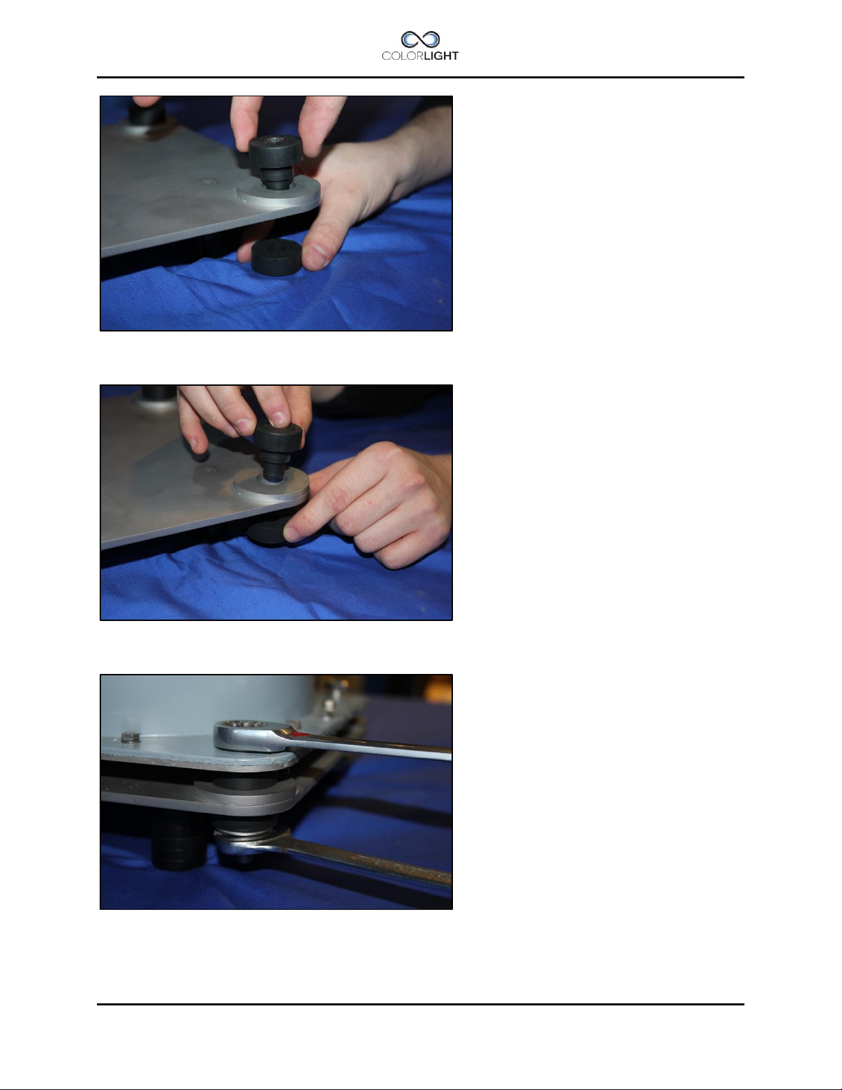
2. Push the dampers tube part thru the mounting holes in the foundation.
3. Mount the dampers rubber part from other side of the foundation.
4. Lower the searchlight on top of dampers and mount bolt washers and nuts as shown in
figure 1.
INSTALLATION MANUAL CL25, CL35 Page 13
Page 14
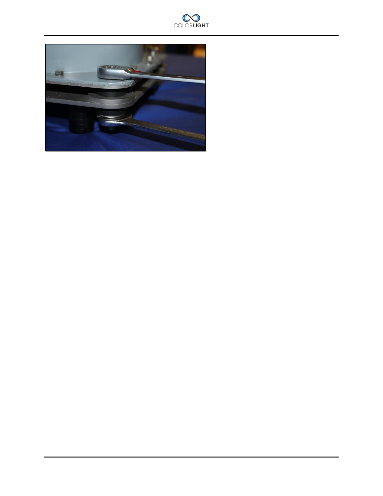
5. The lock nut is tightened with two wrenches size 17mm, tighten nut firmly.
The dampers rubber part will be compressed slightly, after assembly the searchlight will be
rigidly secured but still resistant to vibrations.
Page 14 INSTALLATION MANUAL CL25, CL35
Page 15
CL25-**
1
CLN0166 (HMI / UV bulb 400W) × 1
2
CLS-25330 Front glass sealing × 1
CL35-**
1
CLN0094 (HMI / UV bulb 575W) × 1
2
CLS-35318 Front glass sealing × 1
1
8mm Ratchet Wrench × 1
2
Suction cup tool × 1
3
Lint-free cloth
4
Isopropyl (rubbing) alcohol
CLI-30005, REPLACING THE BULB 7.
Service instruction no: CLI-30005
Revision date: 2013-09-09
Applicable models: CL25-**, CL35-**
Spareparts needed (refer to CL spareparts list)
Tools and supplies required:
Important information
This instruction shows how to replace the bulb and front glass sealing on the CL25 model
equipped with white or UV light but the procedure is the same for the CL35.
It’s recommended to replace the front glass sealing when replacing the bulb, reflector or front
glass to reduce the risk of water ingress between front glass and lamp housing.
Regarding safe handling of bulbs please read: Warnings and Information, page 5
1. Turn off system power before servicing.
2. Start by removing all the four glass holder brackets that keeps the glass in place. Use a
ratchet wrench size 8mm.
INSTALLATION MANUAL CL25, CL35 Page 15
Page 16
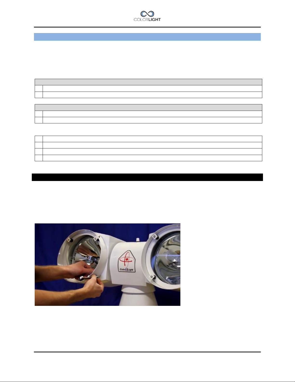
3. Remove the front glass; this is best done with a suction cup tool.
4. Remove the defective bulb from the socket.
5. Remove the old sealing.
Make sure that the flange surface is clean.
Page 16 INSTALLATION MANUAL CL25, CL35
Page 17

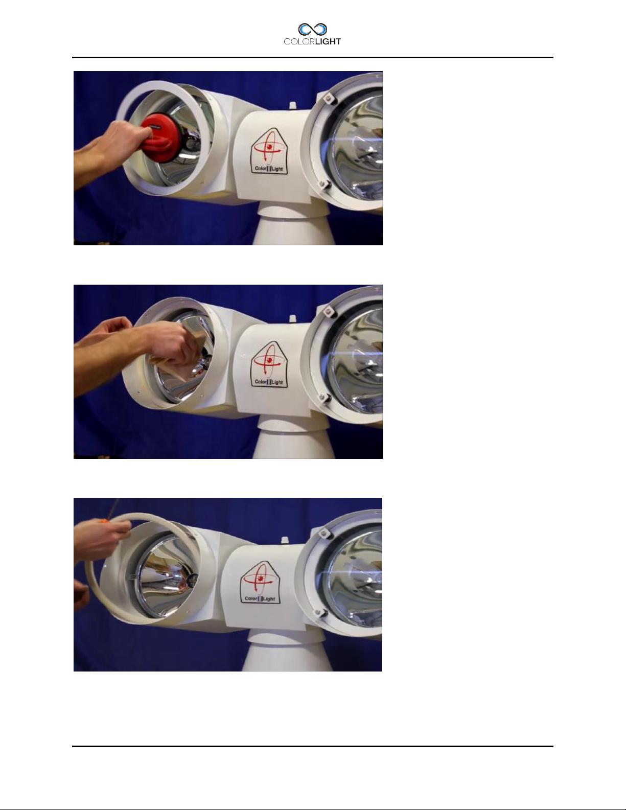
6. Fit the new sealing against the flange.
Make sure to place the sealing joint in line with the lower inner hole of the glass holder
bracket.
7. Press the new sealing against the flange with your hands.
8. Open a package with a new bulb.
Avoid touching the bulb glass with your fingers.
INSTALLATION MANUAL CL25, CL35 Page 17
Page 18

9. Wipe the bulb with a dry, lint-free cloth dipped in isopropyl (rubbing) alcohol.
10. Make sure the bulb is dry before installing it in the socket.
11. Put back the glass again.
Page 18 INSTALLATION MANUAL CL25, CL35
Page 19

12. Fit brackets again by loosely attaching all the screws a few turns.
13. Turn the brackets in the correct position.
14. Tighten all screws crosswise with ratchet wrench size 8mm.
INSTALLATION MANUAL CL25, CL35 Page 19
Page 20

15. Tighten all screws crosswise.
16. Done, turn on power and test the bulb, also remember to perform searchlight
synchronization, please see: 11. Actions after installation or power failure.
Page 20 INSTALLATION MANUAL CL25, CL35
Page 21

ELECTRICAL SYSTEM 8.
IMPORTANT!
The electric supply to the e-box must be disconnected before beginning any work inside
the box; it’s not enough to turn off the internal main switch.
Electrical-box 8.1
The e-box is designed to be as compact as possible but still allow service personnel to easily
replace any broken component.
The design consists of a sandwich construction where the upper section plate is the searchlight
connection part and the bottom section plate is the electronic lamp driver part.
By removing the entire assembly plate from the cabinet, you can lift and slide out the bottom
section plate and if needed replace individual driver or replace the entire plate.
The cabinet is fan cooled and the fan starts only when the lights are on.
INSTALLATION MANUAL CL25, CL35 Page 21
Page 22

Color///Light
Relay NC
Relay NC
Relay Common
0V (white)
Ext. Fan (grey)
n/c (pink)
CAN L (yellow)
CAN H (green)
+24V (brown)
RS232
RS485
Opto1A ->
0V
24Vdc from
PSU
To system
fan in box
Fuse T6,3A
Relay driver
Right(CL20)
Relay driver
Left(CL20)
Alarm Output
Signalcable
to searchlight
Buttons for
navigation
LD01, Left
lampdriver
LD02, Right
lampdriver
Cabinet card 8.2
Color Lights control system is stable and future-proof, and the cabinet card is equipped with a
number of inputs and outputs as to allow the communication with the searchlight but also
communicate with computers, radio receivers, limit switches etc. (via optocoupler).
On the output side, we have relay controlled alarm output (NO, NC) for external alarm handling
and outputs for controlling relays (via optocoupler).
Opto 1C <Opto 2A ->
Opto 2C <24Vdc
RS422
Menu
navigation
See:
Menu
Page 22 INSTALLATION MANUAL CL25, CL35
Page 23

Power supply
240W/24V
Light fuse F01
(left light)
Light fuse F02
(right light)
1- Earth (PE)
3- Phase (L)
4- Earth (PE)
8- LD02 +
12 – RS232/485
14 – GND
15 – 0V
16 – 24Vdc/2A
9 – Relay (NO)
– Relay (COM)
11 – Relay (NC)
Mains
100-240 VAC
50/60 Hz
Powercable to
searchlight
Alarm output
RS232/RS485
24Vdc for
Ethernetswitch
Electrical-box overview 8.3
E-box
LD01
LD02
Main switch
Q01
Fuse T6,3A
Fuse F03
T2A
Fuse F04
T2A
panels and/or
2- Neutral (N)
5- LD01 -
6- LD01 +
7- LD02 -
10
13 – RS232/485
INSTALLATION MANUAL CL25, CL35 Page 23
Page 24

1
Screwdriver 0,6×3,5 mm
2
Adjustable wrench type Bacho 8071
3
Wrench 13 mm
4
1 Electrical box
1 Shield Connection
Electrical box installation 8.4
Tools and supplies required:
Important information
The complete system is undergoing final testing before delivery and therefore has the
searchlight cables installed in box.
1. Ensure that the switch Q01in box is set to off.
2. Remove all the cables in the terminals, the terminals are push-in type and the wire is
released easily by pressing the orange button with a screwdriver while pulling lightly in
the wire.
3. Loosen the cable glands with an adjustable wrench and pull out the cables.
4. Mount the electric box on a firm foundation with the help of the wall brackets.
5. Install in reverse order and pay special attention so that the cables shields are mounted
correct in the cable glands, see figure 2 below for guidance.
Cables are connected according to the wiring diagram and double-checked before the
power is turned on using the main switch Q01 in the electric box.
Page 24 INSTALLATION MANUAL CL25, CL35
Page 25

1. Power cable
Fuse Holder
2. Ethernet cable
3. Earth wire
3
2
1
Wire #2
+
Wire #1
-
Operator panel connections 8.5
The operator panel is designed to be immersed into the bridge panel, for dimensions, see
drawing in section 17.2.1 Operator Panel.
The following connections are available on the back of the panel:
1. Power supply 9-28 VDC via local power supply on the boat or 24VDC via terminals in
the E-box. One of the benefits of supplying power to the panel from the box is that the
panel will be de-energized together with the e-box via the main switch.
2. Ethernet connection directly to the electrical cabinet or Ethernet switch via RJ45
connector. Shielded Keystone Modular Feed through Coupler, RJ45-RJ45 included.
3. Earth connection to the panel, this is needed to suppress electrical disturbances and
prevent ESD discharge damaging.
Electrical protection:
The panel is protected against wrong polarity and over-current protected by a fuse on the back,
type: T1A (Slow-Blow glass fuse 5x20mm).
INSTALLATION MANUAL CL25, CL35 Page 25
Page 26

Pin
T568A
Pair
T568B
Pair
T568A
Color
T568B
Color
Pins on plug face
1 3 2
white/green
stripe
white/orang
e stripe
2 3 2
green solid
orange solid
3 2 3
white/orang
e stripe
white/green
stripe
4 1 1
blue solid
blue solid
5 1 1
white/blue
stripe
white/blue
stripe
6 2 3
orange solid
green solid
7 4 4
white/brown
stripe
white/brown
stripe
8 4 4
brown solid
brown solid
1
8
Ethernet wiring 8.6
ColorLight searchlight systems should be connected to their own dedicated network; they
should never be connected into the vessels existing computer network.
An Ethernet cable supplied by ColorLight complies with the standard TIA/EIA-568-B and is
always tested together with the complete searchlight system to ensure full functionality.
If customers choose to assemble their own Ethernet cables they must be of type FPT Cat5 or
better and the connections should be done according to the following information.
Note that the only difference between T568A and T568B is that pairs 2 and 3 (orange and
green) are swapped. Both configurations wire the pins "straight through", i.e., pins 1 through 8
on one end are connected to pins 1 through 8 on the other end. Also, the same sets of pins
connect to the opposite ends that are paired in both configurations: pins 1 and 2 form a pair, as
do 3 and 6, 4 and 5, and 7 and 8.
One can use cables wired according to either configuration in the same installation without
significant problem. The primary thing one has to be careful of, is not to accidentally wire the
ends of the same cable according to different configurations
Page 26 INSTALLATION MANUAL CL25, CL35
Page 27

1
8
7
6
5 9 2
3
4
1
OPERATOR PANEL, OVERVIEW 9.
1. "Soft button": the function appears in the display window next to the button.
2. Left lamp on/off, standard for -12, -21 (optional for -11, -22 if “Single lamp mode” = On *1).
3. Left focus (same function as No.4 *2), (move left to spot *3).
4. Left focus (same function as No.3 *2), (move left to flood *3).
5. Right lamp on/off, standard for -12, -21 (optional for -11, -22 if “Single lamp mode” = On *1).
6. Right focus (same function as No.7 *2), (move right to spot *3).
7. Right focus (same function as No.6 *2), (move right to flood *3).
8. Joystick.
9. Display.
*1 See User’s Manual 11.8.6.5 Single lamp mode (standard function available from ver. 0.5.3.11).
*2 Continuous focus (standard), see 15.1 Type 1, continuous focus.
*3 Absolute focus (optional for CL25) see 15.2 Type 2, absolute focus.
Note: Several sections of the manual refer to the above figures.
INSTALLATION MANUAL CL25, CL35 Page 27
Page 28

DISPLAY SYMBOLS AND MESSAGES 10.
Symbol for switched off white light.
Symbol for switched on white light.
Error symbol for white light indicates a problem during switch on or if the bulb
breaks down during operation. The operator has three switch-on attempts in a two
minute interval without setting the sum alarm output.
Symbol for switched off UV light (black light).
Symbol for switched on UV light (black light).
Error symbol for UV light indicates a problem during switch on or if the bulb breaks
down during operation. The operator has three switch-on attempts in a two minute
interval without setting the sum alarm output.
Symbol for any electro-mechanic error. Might be referred as an over voltage or
over current for motor drivers. Communication error with motor drivers will result in
the same symbol. This error symbol can be reset by simply enter the main menu
and select status. Then press “dismiss”. If over current have occurred the problem
might be referred as a stucked lamp housing – check for any icing issues. Each
axis has its own symbol showing in upper left or right corner of the display.
Page 28 INSTALLATION MANUAL CL25, CL35
Page 29

Message
Fault
Communication error
Transmission issues on the CAN bus
Over current
Overcurrent protection triggered, movement blocked
Over voltage
Overvoltage protection triggered, voltage to searchlight motordriver/s
have exceeded 30Vdc.
Under voltage
Undervoltage protection triggered, voltage to searchlight
motordriver/s has fallen below 10Vdc
OPWDT (message in box only)
Ethernet communication broken to all panels, see (4.1) OP WDT.
Fault auto-resets if contact is restored with at least one panel
This symbol indicates that the bulb has less than 200 hours left of expected
lifetime. This warning can be chosen by the operator to be shown or not. please
see User’s Manual, 11.8.4 Lamp life for more detailed instruction.
Each bulb has its own symbol showing in the lower left or right corner of the
display.
This symbol indicates that the expected lifetime of the bulb now has expired. The
only way to reset this symbol is by entering the “Usage Stats” menu at the
diagnostic display inside the electrical box. See 16.4 Category 3: Usage Stats.
Certainly this reset should only be done together with a bulb replacement!
This symbol and a similar symbol indicate the direction of the lamp housing both
for the vertical axis and for the horizontal axis. The arrows in the shown symbol
indicate the elevation angle for the vertical axis according to the horizontal-plane.
For the horizontal symbol and axis these small arrows indicate if the housing is
directed to the left, front, right or back of the centerline.
If the arrows are replaced by question marks then the system needs to be
internally calibrated. This is the normal state after power up after a total power loss
to the system. The easiest way to do the internal calibration is by simply choose
the “Park” in the quick start menu, please see User’s Manual 10.6 Off and park.
Ebox alarm relay 10.1
The searchlights electrical and mechanical condition are constantly monitored
and if there is a malfunction in the system this is indicated by icons in the panel
display with clarifying warning messages found in the panels status menu.
The control box also has a relay output that can be connected to the boat
monitoring system; see the wiring diagram for connection details.
The following errors trigger the alarm output.
INSTALLATION MANUAL CL25, CL35 Page 29
Page 30

ACTIONS AFTER INSTALLATION OR POWER FAILURE 11.
At system startup, the panels will start to scan the network to find connected electrical boxes,
during this time, the panel software version will be displayed.
If not the panel made contact by displaying home screen within 30 seconds, it may be due to
the following:
Electrical box is not turned on, applies only if the panel has a separate power supply.
There are problems in the network cabling between the electrical box and the operator
panel.
At the first boot after installation or power failure, the searchlight must be synchronized with the
control system.
After installation or power failure of the electric box you can still use the searchlights main
functions like joystick control, light on/off and focus but in order to be able to use positioning
functions such as display indicator*, parking position, sweep*, fixed positions* or surveillance*,
the searchlight must be synchronized with the control system.
The easiest way to synchronize the system after reboot is to enter the quick start menu and
select the “Park” function. Now the searchlight will synchronize and then park if a parking
position has been set.
If necessary the origin can be set after the steps above to give an accurate readout of the
indicator*. To set the origin, please see User´s Manual, section 11.8.6.1 Store origin.
*Standard function for CL25/CL35, from 2014- also standard for CL20
Page 30 INSTALLATION MANUAL CL25, CL35
Page 31

STARTING SYSTEM 12.
When the system is in sleep the buttons and symbols glows with orange light and the display is
totally shut down to save power. Buttons and symbols are always active but dimmed to a lower
intensity during sleep.
Pressing any button on the operator panel will activate the system and the display will now show
the position indicator* image or just the ColorLight logotype. Buttons and symbols are now
brighter and both buttons, symbols and display intensity can be adjusted, please see User’s
Manual, section 11.8.1 Backlight brightness.
*Standard function for CL25/CL35, from 2014- also standard for CL20
INSTALLATION MANUAL CL25, CL35 Page 31
Page 32

JOYSTICK FUNCTIONS 13.
The joystick (8) moves the searchlight horizontally and vertically. There are no limitations to the
movement of the searchlight thanks to the slip ring technology developed by ColorLight.
The more the joystick is moved to its end position the faster the searchlight rotates.
Searchlight rotation speed can be set, please see User’s Manual, section 11.8.5 Maximum
rotation speed.
The vertical axis reaction according to the joysticks movement can be reversed if decided by
operator. To change this reaction please see User’s Manual, section 11.8.3 Joystick direction.
The joystick can also be used to navigate in menus containing more than one choice.
Move the joystick up or down to navigate in the menu. In most menus joystick moved to the right
will act as “OK” button and moved to the left will go back one step as the “Back” button.
Page 32 INSTALLATION MANUAL CL25, CL35
Page 33

SWITCH ON LIGHT 14.
The searchlight is equipped with two bulbs with either double white (CLXX-11) or double UV
(CLXX-22) or a combination of white and UV light.
As default the double white or double UV will be turned on by pressing button(2) or (5), both
lights will then be lit with a slight delay in between, no matter which button is used.
To turn off the light, press button (2) or (5) again.
There are however occasions when it may be useful to give each bulb a dedicated light button,
this setting is done in the "Single lamp mode" menu, please see User’s Manual, section 11.8.6.5
Single lamp mode.
If the light is a combination of white/UV, light will always be lit separately. Button (2) will lit left
light and button (5) the right light. To turn off light, press the same button again.
In the bottom part of the display there are two sun-symbols that indicates the status of each
bulb.
CL25 and CL35
If the system is unable to switch on the bulbs there will be a red exclamation mark over the sunsymbol for the no working bulb. This error might occur if the operator decides to switch on a
bulb that recently has been shut off without any time to cool down before the next switch on.
Normally wait a few seconds (the longer the better) and try again. The system accepts three
turn on attempts (initiated by the operator) in a two minute time interval before the sum-alarm is
activated.
If the bulb breaks during operation the sum-alarm will be activated directly. The error symbol
with the exclamation mark over the sun-symbol will show again in the display over the
corresponding bulb.
There is a bulb warning feature in the system. This warning can be chosen by the operator to be
shown or not by switch on or off the function in the settings menu, please see User’s Manual,
section 11.8.4 Lamp life.
This warning feature will show a white triangle symbol when the estimated bulblife left is
less than 200 hours. The symbol will be shown at the displays bottom left or right corner
according to left or right bulb.
When the expected lifetime is expired the white triangle will change to a red triangle.
The only way to reset this symbol is by entering the “lamp life” menu at the diagnostic
display inside the electrical box. To get to the correct menu use the three buttons below
the display. Under the lamp life menu there are two choices: “usage statistics” and “reset
counters”. Select “reset counters” and select the corresponding lamp housing for which the
counter should be reset. Certainly this reset should only be done together with a bulb
replacement!
INSTALLATION MANUAL CL25, CL35 Page 33
Page 34

Flood
Spot
FOCUS 15.
Type 1, continuous focus (standard) 15.1
Note: Button numbers below refers to OPERATOR PANEL, OVERVIEW.
Pressing the focus buttons (3) or (4) changes the focus for the left lamp house and buttons (6)
or (7) changes focus for the right lamp house.
Release the button when the required focus is found.
As long as a focus button is pressed the bulb moves in and out which changes the focus of the
light between 4-20 degrees for model CL20, CL25 and 3-20 degrees for model CL35.
Note: Pressing button (3) and (6) or (4) and (7) at the same time will cause an electric collision
which stops the focus from changing. Releasing one of the buttons will continue the focusing of
the pressed button. To focus with both lights simultaneously hold (3) and (7) or (4) and (6).
Page 34 INSTALLATION MANUAL CL25, CL35
Page 35

Flood
Spot
Focus position
Beam angle
(degrees)
100%
Max spot
≈ 4,0
80%
≈ 7,2
60%
≈ 10,5
40%
≈ 13,5
20%
≈ 16,8
0%
Max flood
≈ 20,0
Type 2, absolute focus (optional for CL25) 15.2
Note: Button numbers below refers to OPERATOR PANEL, OVERVIEW.
This feature enables adjusting a defined beam width (focus) of the lamps by means of a step
motor.
Focusing from control panel is made in 20%-steps by pressing the focus button for spot or flood
repeatedly, or, if the buttons is held longer than 0,6 second, the focus moves directly to desired
end position.
This focus unit is also controllable via the serial interface RS232 or RS485 and can then be
commanded to any focus position within the range 4-20 degrees (stepless control).
Pressing the spot buttons changes the focus towards spot on corresponding lamp house in
predefined steps according to table above.
Pressing the flood buttons changes the focus towards flood.
Release the button when the required focus is found.
Note: If the system is manually rebooted or starts up after a power failure, the focus unit will
always automatically move back to 0% in order to avoid the risk of burning surfaces on the boat
with the intense light beam.
INSTALLATION MANUAL CL25, CL35 Page 35
Page 36

1. About
1.1 MAC Address
1.2 IP Address
1.3 Light Model
1.4 SW Version
2. Diagnostics
2.1 Start
2.2 View Results
3. Usage Stats
3.1 Left Light
3.2 Right Light
3.3 Reset Left
3. 4 Reset Right
4. Settings
4.1 OP WDT
4.2 OP WDT Stats
4.3 OP WDT Reset
Right
OK
Down
CABINET CARD MENU SYSTEM 16.
This chapter describes the menu system of the ColorLight Cabinet Card displayed on the onboard LCD.
Menu navigation 16.1
The user interacts with the menu system using the three buttons, the “Down” button, the “Right”
button and the “OK” button.
Down Button 16.1.1
The main function of the “Down” button is to shift between the menu categories. It also has two
alternate generic functions.
1. While in submenus listing items of various types the “Down” button scrolls down in the list.
2. While entering a value of some sort, the “Down” button decrements that value.
Right Button 16.1.2
The main function of the “Right” button is to shift between the submenus of the selected menu
category. It also has two alternate generic functions.
1. While in submenus listing items of various types the “Right” button scrolls up in the list.
2. While entering a value of some sort, the “Right” button increments that value.
OK Button 16.1.3
The “OK” button enters and exits submenus.
Page 36 INSTALLATION MANUAL CL25, CL35
Page 37

Category 1: About 16.2
In this chapter all of Category 1 menu items will be explained.
(1.1) MAC Address 16.2.1
Displays the MAC address of the Cabinet Card, according to the standard (IEEE 802) in six
groups of two hexadecimal digits, separated by colons (‘:’), in transmission order, e.g.
“01:23:45:67:89:ab”. One exception from the standard is made, the leftmost colon is missing,
due to the 16 character limit of the LCD.
16.2.2
Displays the IPv4 address of the Cabinet Card, in four groups of one to three decimal digits,
separated by dots (‘.’), e.g. “169.254.17.5”.
(1.2) IP Address
(1.3) Light Model 16.2.3
Displays the searchlight model that the Cabinet Card is configured to use, e.g. “Model: CL25-
12”.
(1.4) SW Version 16.2.4
Displays the firmware version of the Cabinet Card, e.g. “0.1.2.3”.
INSTALLATION MANUAL CL25, CL35 Page 37
Page 38

Category 2: Diagnostics (support tool) 16.3
In this chapter all of Category 2 menu items will be explained.
(2.1) Start 16.3.1
Press the OK button to run the on-board diagnostic test suite to sense the electrical and
mechanical condition of the searchlight. (contact Colorlight for help with this feature).
T1. Measurement of voltage and current when the searchlight is in “non operating mode”
T2 (HCW). Measurement of current drawn by the horizontal motor; motor rotates clockwise for
30 seconds.
T3 (HCCW). Measurement of current drawn by the horizontal motor; motor rotates
counterclockwise for 30 seconds.
T4 (VCW). Measurement of current drawn by the vertical motor; motor rotates clockwise for 30
seconds.
T5 (VCCW). Measurement of current drawn by the vertical motor; motor rotates
counterclockwise for 30 seconds and the value is temporary stored.
T6 (Rfoc). Measurement of current drawn by the right focus motor; runs for 30 seconds.
T7 (Lfoc). Measurement of current drawn by the left focus motor; runs for 30 seconds.
T8 (H MAG). Test of horizontal magnetic sensor; the horizontal motor is running at full speed for
a predetermined time and number of triggers is recorded.
T9 (V MAG). Test of vertical magnetic sensor; the vertical motor is running at full speed for a
predetermined time and number of triggers is recorded.
T10 (Lights). Lamp test; both lights should ignite and be lit for 30 seconds.
To avoid burning anything with the bright light the test is performed with both axis rotating in half
speed. The result is temporary stored.
T11 (OP count). Counting the number of connected operator terminals in the network.
(2.2) View Results 16.3.2
Displays the result of the last run diagnostics test suite.
Use the “Down” button to cycle through the tests results.
Use the “Right” button to cycle through different test result information for the selected test.
Only applicable for test “T1” and test “T10”.
Page 38 INSTALLATION MANUAL CL25, CL35
Page 39

Category 3: Usage Stats 16.4
In this chapter all of Category 3 menu items will be explained.
(3.1) Left Light 16.4.1
Displays the usage of the left light source in hours:minutes:seconds, e.g. “Left: 1:23:45”.
(3.2) Right Light 16.4.2
Displays the usage of the right light source in hours:minutes:seconds, e.g. “Right: 1:23:45”.
(3.3) Reset Left 16.4.3
Resets the usage counter of the left light source.
A confirmation message, “If sure press OK”, is displayed upon entering the menu. Press the
“OK” button at this point to reset the counter and exit the menu. Press the “Down” or “Right”
button to exit the menu without resetting the counter.
(3.4) Reset Right 16.4.4
Resets the usage counter of the right light source.
A confirmation message, “If sure press OK”, is displayed upon entering the menu. Press the
“OK” button at this point to reset the counter and exit the menu. Press the “Down” or “Right”
button to exit the menu without resetting the counter.
INSTALLATION MANUAL CL25, CL35 Page 39
Page 40

Category 4: Settings 16.5
In this chapter all of Category 4 menu items will be explained.
(4.1) OP WDT 16.5.1
Ethernet communications guard OP WDT (Operator Panel Watchdog Timer)
This searchlight is built for use on long distances and the high-intensity light from the searchlight
can, if set at a narrow beam, cause severe damage to surfaces closer than 1 meter. To avoid
that the searchlight is forgotten with the light on, always use the feature “off and park” when not
using the searchlight.
If however a hardware failure occurs that breaks the Ethernet communication between the box
and operator panel, a safety function will step in and automatically turn off the light within 3
seconds, the OP WDT will also interrupt an ongoing sweep or surveillance activity.
If an OP WDT event has occurred an error message will be displayed in the electrical box and
the alarm relay (CL25/35) will trigger. When communication returns the message will disappear
and the alarm will be reset.
For multiple panel systems: OP WDT will step in only when communication is lost to all panels.
Possible reasons why OP WDT turn off the lights:
The power supply to the operator panel is broken.
The power supply to the Ethernet switch (if any) is broken.
Broken Ethernet cable between electrical box/ Ethernet switch (if any) and operator
panel.
OP WDT is disabled by default, to enable press “OK” button in menu “4.1 OP WDT” screen and
press the “Down” or “Right” button to toggle the function on/off.
Page 40 INSTALLATION MANUAL CL25, CL35
Page 41

(4.2) OP WDT Stats 16.5.2
Displays a counter that keeps track of the number of times the Ethernet communication has
recovered from an OP WDT event.
In case of suspected cable problems with connected operator panels, this counter can be
helpful when troubleshooting.
(4.3) OP WDT Reset 16.5.3
Resets the OP WDT counter.
A confirmation message, “If sure press OK”, is displayed upon entering the menu. Press the
“OK” button at this point to reset the counter and exit the menu. Press the “Down” or “Right”
button to exit the menu without resetting the counter
INSTALLATION MANUAL CL25, CL35 Page 41
Page 42

TYPE
MODEL
SOURCE
RANGE
Dual White
CL25-11
HMI/HMI
3000 m
Combination White/UV
CL25-12 (CL25-21)
()
HMI/UV
2000 m/1000 m
Dual UV
CL25-22
UV/UV
1500 m
Daytime camera module
Suffix -1 on above
Optional
Optional
IR-camera module
Suffix -2 on above
Optional
Optional
LIGHT
Technology
Metal Halide
Light source
2 x 400W HMI
Color Temp (white light)
6000 K
CRI (white light)
> 90 Ra
Luminus flux (CL25-11)
66 000 lm
Light intensity (CL25-11)
10,7 M candela
Range (CL25-11)
3000 m (1 lux @ 50 m diameter)
Beam width
4-20 deg
Firefighting (CL25-11)
250 m (50-170 lux @ 14 m diameter
MECHANICAL
Technology
Slipring. Brushless digital controlled servo
Horizontal movement
Unlimited movement
Vertical movement
Unlimited movement
Speed both axis
Stepless 0-33 deg/sec
STANDARD DIRECT
CONTROLLED
Light on/off
Focus (adjustable)
Rotation speed, stepless
STANDARD
FUNCTIONS
System activation
Parking mode
Language version
User settings
System information
Single lamp mode (11/22)
STANDARD PACK 1
Position indicator
OPTIONAL PACK 2
Auto sweeping
Fixed positions
Surveillance
OPTIONAL PACK 3
Synchronized control
OPTIONAL HARDWARE
Wireless radio control
Absolute focus (not for retrofitting)
Thermal camera unit (not for retrofitting)
Fiber optic control cable
Daylight camera unit (not for retrofitting)
Customized color
Extra remote panel (s)
Wet paint (AWL grip or similar)
External power supply for panel (s)
Polished stainless
Ethernet switch, 5 port and 8 port
Upside-down installation
Customization upon request
Power
consumption
1070 W (max load)
4,7 A @ 230 VAC (max load)
Heat load
15 W / 85 W (standby/max load)
Refector size
2 x dia 210 mm
Bulb life
650 hours
Ballast
No external ballast
Signal cable
3x2x0,75 shielded, twisted pair (from 2014-03- 3x2x1)
Power cable
5G1,5 shielded
OP3G cable
Ethernet CAT5-FTP Fiber available for long distance
Serial cable
RS485/RS232 Optional. ICD for external control
SEARCHLIGHT BODY
EBOX
OPERATOR PANEL
Weight (kg)
30
17
0,5
Static size (cm)
42x75x53 cm *
40x30x21 cm *
13x9x6 cm *
Material
Acid proof stainless steel 1.4401
Coated steel
Anodized aluminum / ABS
Paint
Powder coat white RAL 9016
Powder coat grey RAL 7035
Anodized black
IP-Class
IP66
IP22
IP54
Operating temp range
-40º / +70º Celsius
+5º / +60º Celsius
-20º / +70º Celsius
Input power
Powered from ebox
100-240 VAC 50/60 Hz
9-28 VDC (max 200 mA @ 24V)
Specifications CL25 17.1
MODEL RANGE
PERFORMANCE
FUNCTIONS
TECHNICAL DATA CL25 17.
TECHNICAL DATA
* see drawing CL25 for detailed info
Page 42 INSTALLATION MANUAL CL25, CL35
Page 43

Mechanical drawings 17.2
Operator Panel 17.2.1
INSTALLATION MANUAL CL25, CL35 Page 43
Page 44

Electrical box 17.2.2
Page 44 INSTALLATION MANUAL CL25, CL35
Page 45

Searchlight CL25 17.2.3
The searchlights cable glands are rated IP68 but for extra protection during heavy weather
situations it’s still recommendable to install the searchlight so the cable exits are facing the
stern.
The longer part of the lamp house peak shall be set down. This extra long peak is to reduce
disturbing reflections from the foredeck, if any.
INSTALLATION MANUAL CL25, CL35 Page 45
Page 46

TYPE
MODEL
SOURCE
RANGE
Dual White
CL35-11
HMI/HMI
5300 m
Combination White/UV
CL35-12 (CL35-21)
()
HMI/UV
3500 m/1200 m
Dual UV
CL35-22
UV/UV
1700 m
Daytime camera module
Suffix -1 on above
Optional
Optional
IR-camera module
Suffix -2 on above
Optional
Optional
LIGHT
Technology
Metal Halide
Light source
2 x 575W HMI
Color Temp (white light)
6000 K
CRI (white light)
> 90 Ra
Luminus flux (CL35-11)
98 000 lm
Light intensity (CL35-11)
28,7 M candela
Range (CL35-11)
5300 m (1 lux)
Beam width
3-20 deg
Firefighting (CL35-11)
250 m (50-230 lux @ 12 m diameter
MECHANICAL
Technology
Slipring. Brushless digital controlled servo
Horizontal movement
Unlimited movement
Vertical movement
Unlimited movement
Speed both axis
Stepless 0-20 deg/sec
STANDARD DIRECT
CONTROLLED
Light on/off
Focus (adjustable)
Rotation speed, stepless
STANDARD
FUNCTIONS
System activation
Parking mode
Language version
User settings
System information
Single lamp mode (11/22)
STANDARD PACK 1
Position indicator
OPTIONAL PACK 2
Auto sweeping
Fixed positions
Surveillance
OPTIONAL PACK 3
Synchronized control
OPTIONAL HARDWARE
Wireless radio control
Absolute focus (not for retrofitting)
Thermal camera unit (not for retrofitting)
Fiber optic control cable
Daylight camera unit (not for retrofitting)
Customized color
Extra remote panel (s)
Wet paint (AWL grip or similar)
External power supply for panel (s)
Polished stainless
Ethernet switch, 5 port and 8 port
Upside-down installation
Customization upon request
Power
consumption
1460 W (max load)
6,5 A @ 230 VAC (max load)
Heat load
19 W / 120 W (standby/max load)
Refector size
2 x dia 410 mm
Bulb life
1 000 hours
Ballast
No external ballast
Signal cable
3x2x0,75 shielded, twisted pair (from 2014-03- 3x2x1)
Power cable
5G1,5 shielded
OP3G cable
Ethernet CAT5-FTP Fiber available for long distance
Serial cable
RS485/RS232 Optional. ICD for external control
SEARCHLIGHT BODY
EBOX
OPERATOR PANEL
Weight (kg)
80
17
0,5
Static size (cm)
67x113x75 cm *
40x30x21 cm *
13x9x6 cm *
Material
Acid proof stainless steel 1.4401
Coated steel
Anodized aluminum / ABS
Paint
Powder coat white RAL 9016
Powder coat grey RAL 7035
Anodized black
IP-Class
IP66
IP22
IP54
Operating temp range
-40º / +70º Celsius
+5º / +60º Celsius
-20º / +70º Celsius
Input power
Powered from ebox
100-240 VAC 50/60 Hz
9-28 VDC (max 200 mA @ 24V)
Specifications CL35 18.1
MODEL RANGE
PERFORMANCE
FUNCTIONS
TECHNICAL DATA CL35 18.
TECHNICAL DATA
* see drawing CL35 for detailed info
Page 46 INSTALLATION MANUAL CL25, CL35
Page 47

Mechanical drawings 18.2
Operator Panel 18.2.1
INSTALLATION MANUAL CL25, CL35 Page 47
Page 48

Electrical box 18.2.2
Page 48 INSTALLATION MANUAL CL25, CL35
Page 49

Searchlight CL35 18.2.3
The searchlights cable glands are rated IP68 but for extra protection during heavy weather
situations it’s still recommendable to install the searchlight so the cable exits are facing the
stern.
The longer part of the lamp house peak shall be set down. This extra long peak is to reduce
disturbing reflections from the foredeck, if any.
INSTALLATION MANUAL CL25, CL35 Page 49
Page 50

SUPPORT 19.
If you have questions about the searchlight and its features, please contact ColorLight technical
support worldwide, see www.colorlight.com for contact details.
Or contact ColorLight head office:
ColorLight AB
Engineering-ColorLight
cl@colorlight.com
Phone: +46 353 8270
Fax: +46 35 38279
Need technical Support?
Follow the link below and fill out the form, we will contact you shortly.
http://www.colorlight.com/tech-support/service-request.html
If you want to upgrade your system with additional options as described in User’s Manual,
section (11.8.6.7), please contact:
ColorLight AB
Phone: +46 35 38280
Fax: +46 35 38279
www.colorlight.com
info@colorlight.com
Delivery address:
ColorLight AB
Kassakällor Erikslund 917
SE-313 95 Åled
Sweden
Notes:
Page 50 INSTALLATION MANUAL CL25, CL35
Page 51

INSTALLATION MANUAL CL25, CL35 Page 51
Page 52

VISIBILITY | VERSATILITY | VALUE
We look forward to serve you with the Future Searchlight Solution - wherever you are
ColorLight AB
Kassakällor
SE-313 95 Åled
Sweden
Phone: +46 35 38280
Fax: +46 35 38279 www.colorlight.com
e-mail: info@colorlight.com
 Loading...