

Colombo R Series, Privacy M440 - 2"" BS, Passage M400 - 2"" BS, Keylock M450 - 2"" BS, Double Dummy D190 Installation Instructions Manual
...Page 1
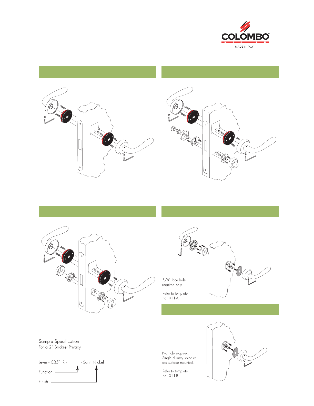
MAGNETIC | EURO MORTISE MOUNTING
R SERIES
SB ”2 - 044M YCAVIRPSB ”2 - 004M EGASSAP
Refer to template no. 004A
Refer to template no. 006A
Refer to template no. 005A
091D YMMUD ELBUODSB ”2 - 054M KCOLYEK
SINGLE DUMMY D185
M440
Mortise stocked in 2" back-set. Also available in 2 3/8" back-set.
Page 2
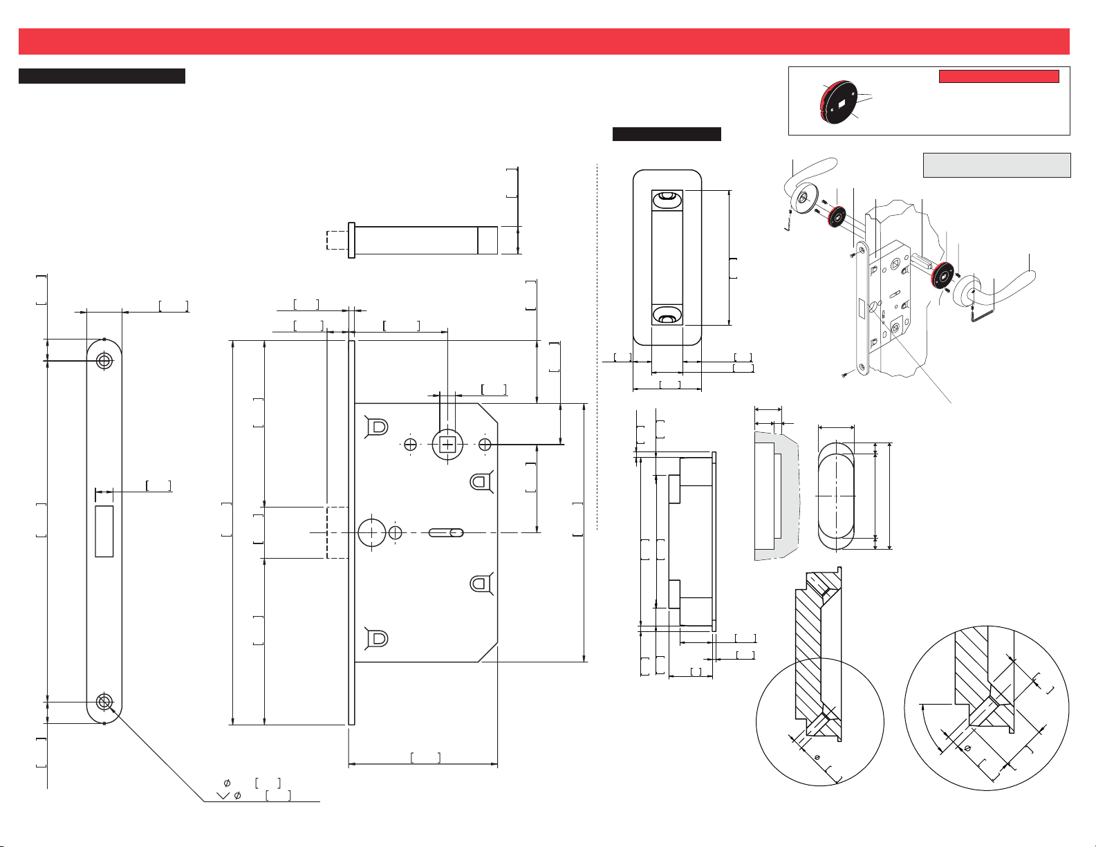
INSTALLATION INSTRUCTIONS FOR PASSAGE EURO MAGNETIC MORTISE LOCK R M400 - non-bored door condition
Euro Magnetic Passage Mortise
TOOLS REQUIRED:
5/8 Dia. Drill Bit, 5/8 Router Bit for Pocket,
7/8 Router Bit for face plate and Phillips Screwdriver.
11mm
7/16"
174mm
6 7/8"
11/16"
3/8"
18mm
9mm
196mm
7 11/16"
7/16"
85mm
3 3/8"
26mm
1"
1/8"
3mm
11mm
2"
50.5mm
5/16"
8mm
14mm
9/16"
32mm
1 1/4"
45mm
1 3/4"
21mm
13/16"
132mm
5 3/16"
Passage Strike
1/4"
6mm
1/16"
2mm
2 3/8"
60mm
1"
25mm
1/4"
6mm
1 7/8"
47mm
5/16"
7/16"
1 15/16"
49mm
7mm
11mm
15,5
11,5 4
Red side
10
9
Milling diagram
20
Black side
8
Required
hole
positioning
7
47,8 6,36,3
60,4
PLEASE NOTE
Springs are handed. Black must be
facing you for Right Hand Lever.
Red for Left Hand Lever.
PARTS INCLUDED WITH YOUR
NEW PASSAGE LOCK
6
5
4
3
Passage Parts
1. Right Hand Lever Handle (inside)
2. Allen Key
3. Handle Set Screw (2)
4. Screws #8 (4)
5. Spring Pack
(Right Hand inside Shown)
6. Passage Spindle
7. Passage/Privacy Euro Mortise
8. Face Plate Screws (2)
9. Spring Pack (outside)
10. Left Hand Lever Handle (outside)
1
2
11mm
7/16"
2X
3/16"
5/16"
85mm
3 3/8"
5mm
8mm
THRU ALL
X 90°
3"
76mm
1/16"
2mm
1/4"
6mm
7/16"
11mm
1/16"
1mm
5/8"
15
45°
1/8"
4mm
1/8"
5/16"
8mm
1/2"
13mm
4mm
B
Template #004A
Page 3
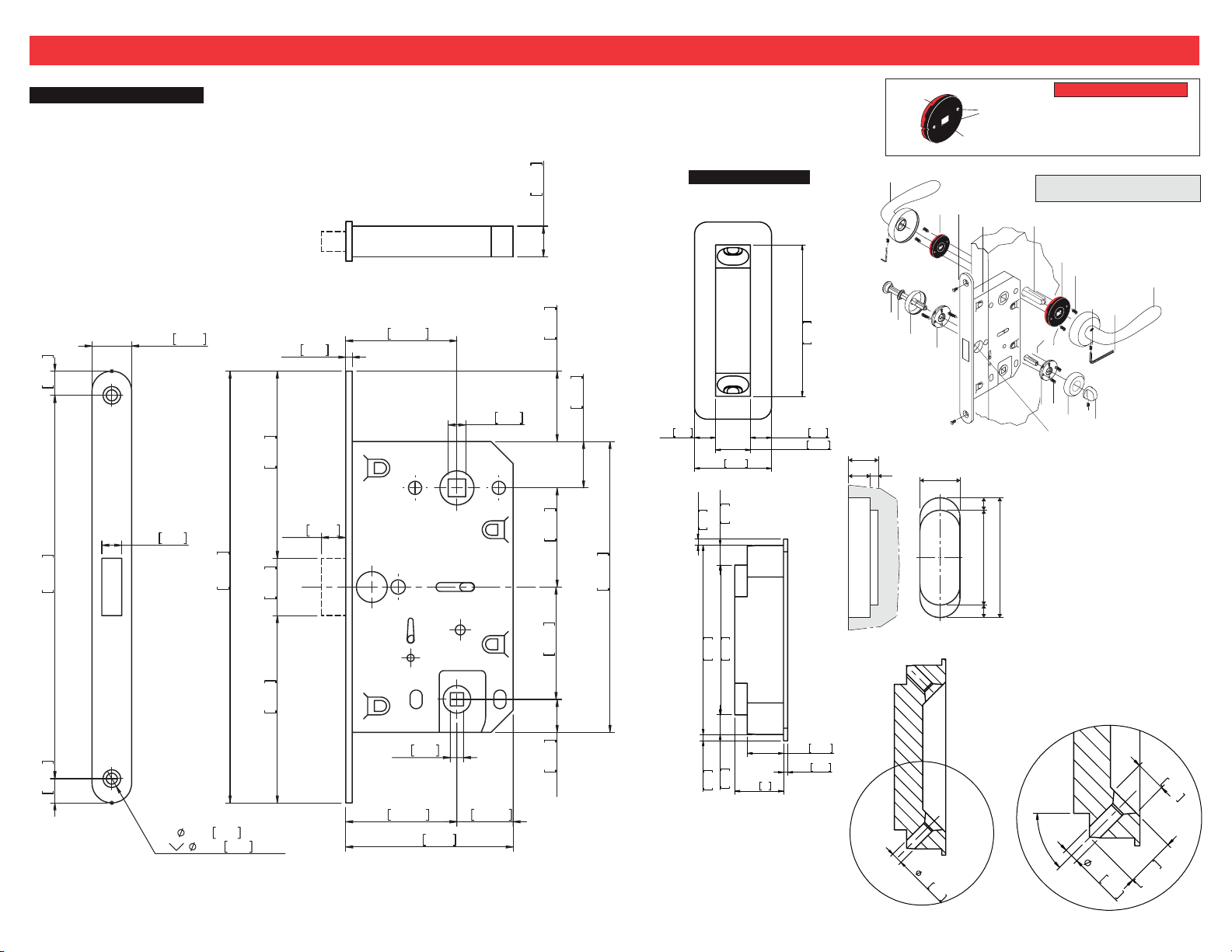
INSTALLATION INSTRUCTIONS FOR PRIVACY EURO MAGNETIC MORTISE LOCK R M440 - non-bored door condition
Euro Magnetic Privacy Mortise
TOOLS REQUIRED:
5/8 Dia. Drill Bit, 5/8 Router Bit for Pocket,
7/8 Router Bit for face plate and Phillips Screwdriver.
11/16"
11mm
7/16"
174mm
6 7/8"
3/8"
18mm
9mm
196mm
7 11/16"
1/8"
85mm
3 3/8"
7/16"
26mm
1"
85mm
3mm
11mm
2"
50.5mm
5/16"
8mm
14mm
9/16"
32mm
1 1/4"
45mm
1 3/4"
51mm
2"
21mm
13/16"
132mm
5 3/16"
Red side
15,5
11,5 4
10
9
9
8
7
6
Milling diagram
20
Privacy Stike
1 15/16"
49mm
1/4"
6mm
1"
25mm
1/4"
1/16"
6mm
2mm
2 3/8"
1 7/8"
60mm
47mm
5/16"
7/16"
7mm
11mm
Black side
8
Required
hole
positioning
7
47,8 6,36,3
60,4
6
PLEASE NOTE
Springs are handed. Black must be
facing you for Right Hand Lever.
Red for Left Hand Lever.
PARTS INCLUDED WITH YOUR
NEW PRIVACY LOCK
5
4
3
4
5
Passage Parts
10. Left Hand Lever Handle (outside)
Privacy Parts
2
3
1
1. Right Hand Lever Handle (inside)
2. Allen Key
3. Handle Set Screw (2)
4. Screws #8 (4)
5. Spring Pack
(Right Hand inside Shown)
6. Passage Spindle
7. Passage/Privacy Euro Mortise
8. Face Plate Screws (2)
9. Spring Pack (outside)
1. Thumbtur n (inside)
2. Thumbtur n Set Screw
3. Rose (inside)
4. Screws #4 (4)
5. Spr ingless Pack (inside)
6. Spr ingless Pack (outside)
7. Rose
8. Washer
9. Emergency Release Spindle
1
2
11mm
7/16"
2X
3/16"
5/16"
5mm
8mm
THRU ALL
X 90°
3 3/8"
2"
1/4"
6mm
50.5mm
3"
76mm
1"
25.5mm
15mm
9/16"
1/16"
2mm
1/4"
6mm
7/16"
11mm
1/16"
1mm
5/8"
15
45°
1/8"
4mm
1/8"
5/16"
8mm
1/2"
13mm
4mm
B
Template #005A
Page 4
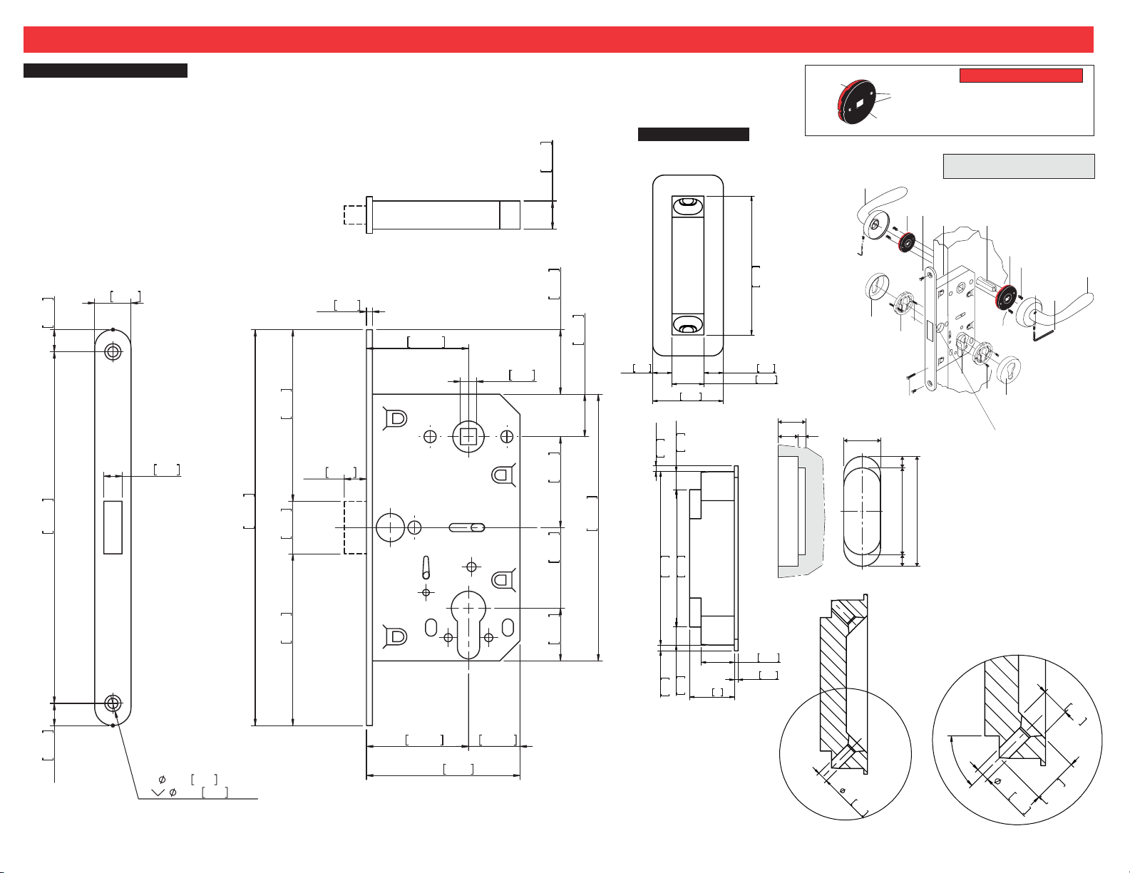
INSTALLATION INSTRUCTIONS FOR KEYLOCK EURO MAGNETIC MORTISE LOCK R M450 non-bored door condition
Euro Magnetic Keylock Mortise
TOOLS REQUIRED:
5/8 Dia. Drill Bit, 5/8 Router Bit for Pocket,
7/8 Router Bit for face plate and Phillips Screwdriver.
11/16"
18mm
11mm
7/16"
85mm
3 3/8"
3/8"
174mm
6 7/8"
9mm
196mm
7 11/16"
7/16"
26mm
1"
85mm
3 3/8"
1/8"
3mm
11mm
2"
50.5mm
5/16"
8mm
14mm
9/16"
32mm
1 1/4"
45mm
1 3/4"
40mm
1 9/16"
26mm
1"
21mm
13/16"
132mm
5 3/16"
1/4"
Keylock Strike
6mm
1/16"
2mm
2 3/8"
60mm
1/16"
2mm
1"
25mm
1/4"
6mm
1 7/8"
47mm
1/4"
6mm
Red side
1 15/16"
49mm
5/16"
7mm
11mm
7/16"
Milling diagram
15,5
11,5 4
7/16"
11mm
1/16"
1mm
5/8"
15
Black side
10
20
Required
hole
positioning
8
9
7
7
5
6
4
47,8 6,36,3
60,4
PLEASE NOTE
Springs are handed. Black must be
facing you for Right Hand Lever.
Red for Left Hand Lever.
PARTS INCLUDED WITH YOUR
NEW KEYLOCK LOCK
6
5
4
3
2
3
2
1
Passage Parts
1. Right Hand Lever Handle (outside)
2. Allen Key
3. Handle Set Screw (2)
4. Screws #8 (4)
5. Spring Pack
(Right Hand outside Shown)
6. Passage Spindle
7. Passage/Privacy Euro Mortise
8. Face Plate Screws (2)
9. Spring Pack (inside)
10. Left Hand Lever Handle (inside)
Locking Parts
1. Profile Escutheon
2. Escutheon Mounting Bracket
Cylindar
3. Profile
4. Cylindar Screws
5. Screws
6. Escutheon Mounting Bracket
7. Profile Escutheon
5/16"
8mm
1
11mm
7/16"
2X
3/16"
5/16"
5mm
8mm
THRU ALL
X 90°
2"
50.5mm
3"
76mm
1"
25.5mm
45°
1/2"
1/8"
4mm
1/8"
4mm
13mm
B
Template #006A
Page 5
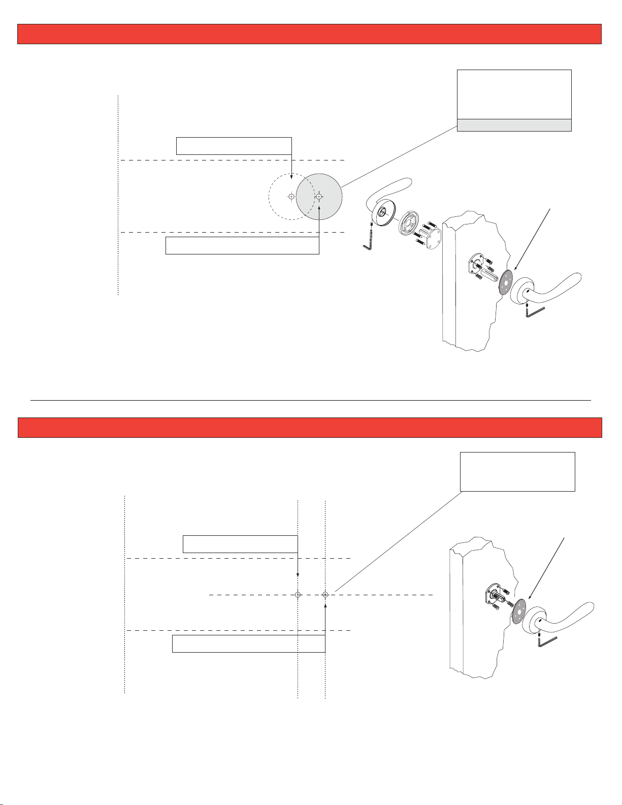
Template for DOUBLE DUMMY D190 -
non-bored door condition
Determine backset
Fold on dotted line - Lay over edge of door
2-3/8” BACKSET TEMPLATE
.
POINT NO. 2 (face bore)
2-3/4” BACKSET TEMPLATE
DOUBLE DUMMY
SPINDLE HOLE
DRILL ONLY IF YOU
HAVE LEVER OR KNOB ON
THIS SIDE OF DOOR
5/8” DIA. (16 mm)
PLASTIC ADAPTOR NOT USED FOR HD
SERIES & ROSES WITH 6MM CONCEPT
Template for SINGLE DUMMY D185 -
Determine backset
Fold on dotted line - Lay over edge of door
Template #011A
non-bored door condition
Use line markers to
locate surface mounted
dummy spindles
PLASTIC ADAPTOR NOT USED FOR HD
SERIES & ROSES WITH 6MM CONCEPT
2-3/8” BACKSET TEMPLATE
2-3/4” BACKSET TEMPLATE
Template #011B
 Loading...