

Coldelite LB-100B Operation And Service Manual
FOREWORD
-
Thank you for selecting COLDELITE to meet today's fast growing
demands. Your COLDELITE freezer has been manufactured at one
of the most modern freezer manufacturing plants in the
our Winston-Salem, North Carolina facility, utilizing the most
advanced equipment and technology available in the industry.
We at COLDELITE, take great pride and care in the manufacture
of each and every freezer, using only the finest components
available, to provide you with years of trouble-free operation.
Over twenty-five years of experience in the manufacturing of
dispensing equipment have guided us in the
pre-jarati~nof this
Operation and Service Manual. PLEASE READ IT CAREFULLY.
it
Keep
for future reference and most of all, follow the instructions
from the very time your machine is put into service.
On the following pages, you will find important information and procedures which describe the proper installation, sanitizing, operation,
and maintenance of your
COLDELITE machine.
We
your full compliance with these instructions will assure you of ex-
cellent performance, trouble-free operation
and a profitable
business for years to come.
U.S.A.,
feel certain that
PACE
A-1
INDEX
PART
PART
PART
PART IV
PART V
1
I1
I11
INSTALLATION
A) UNCRATING 1
8) POSITIONING TifE MACHINE
C) ELECTRICAL REQUIREMENTS
Dl ELECTRICAL CONNECTIONS
El COMPLETING THE INSTALLATION
EXPLAINATION OF CONTROLS.
A) THE SELECTOR SWITCH
8) THE MECHANICAL TIMER
Cl THE DISPENSE HANDLE
Dl THE ELECTRICAL PANEL
El OTHER CONTROLS
INITIAL CLEANING PROCEDURE
ASSE:VBLINC THE FREEZER -10
A)
ASSEMBLING THE aEATER
8) XSSEiL1BLING
SANITIZING TifE FREEZER
........................
.........................
.............
............
.............
.........
.............
.................
..............
................
...............
...................
.............
..............
..............
THE
DISPENSE
................
HEAD
........
-1
.I
Z
3
4
4
4
-6
6
6
-8
8
11
11
-12
PART VI
PART VII
PART VIII
PART IX
STARTING THE FREEZER
OPERATING THE FREEZER 17
TECHNICAL INFORMATION
A) REFRIGERATION 15
8) BEATER MOTOR 15
C) DRIVE SYSTEM 16
MAINTENANCE
A] TROUBLE SHOOTING GUIDE -18
81
PARTS INDENTIFICATION
C) 'NIRINC SCHEMATIC
......................
.......................
.........................
..................
................
................
......................
............
...............
...................
13
15
16
20
24
IMPORTANT
Failure to closely follow set-up, operational and maintenance procedures
may result in damage to the unit and/or void your warranty. Coldelite
Corporation will not be responsible for any machine not properly maintained.
In the event this unit should malfunction, please contact your Coldelite
Distributor or authorized service agency.
PART
INSTALLATI0
1
N
Before starting this procedure, make certain the shipping case does not
show any evidence of having been dropped, tampered with or abused in
such a way as to indicate that its contents may have been damaged in
transit.
IMPORTANT: Should the outside of the shipping case give any indication
of possible hidden damage, state this on the bill of lading before signing.
Contact the carrier immediately and request an inspection of the damage.
If this procedure
is
not adhered to, you will forfeit your right to file a
damage claim and be responsible for subsequent repair costs.
A) UNCRATINC
Proceed as follows:
1.
Remove tho machine from its carton and remove all protective crating
material.
2.
Remove the single screw at the bottom of each side panel,
Remove
the side panels by pulling in a downward and outward direction, allowing
the panel to slide free, The protective plastic coating which is laminated
to the panels czn now be removed by simply peeling off.
8)
POSITIONING
1.
The machine
must be capable of supporting
force
it
if necessary. Remember, when choosing a location, your unit
is air cooled, proper air flow
(6)
six
inches on either side and a minimum of twelve
THE
MACHINE
is
now ready to be positioned onto your counter. The counter
225
Ibs., and should be vibration free, Rein-
will
need to be maintained. Allow at least
(1
the rear of the machine and any obstruction. (Ref. Fig,
PACE
1
2)
inches between
1)
17:
I
Flow
I
Side
I
View
La-1
00B
Front
View
LB-1008
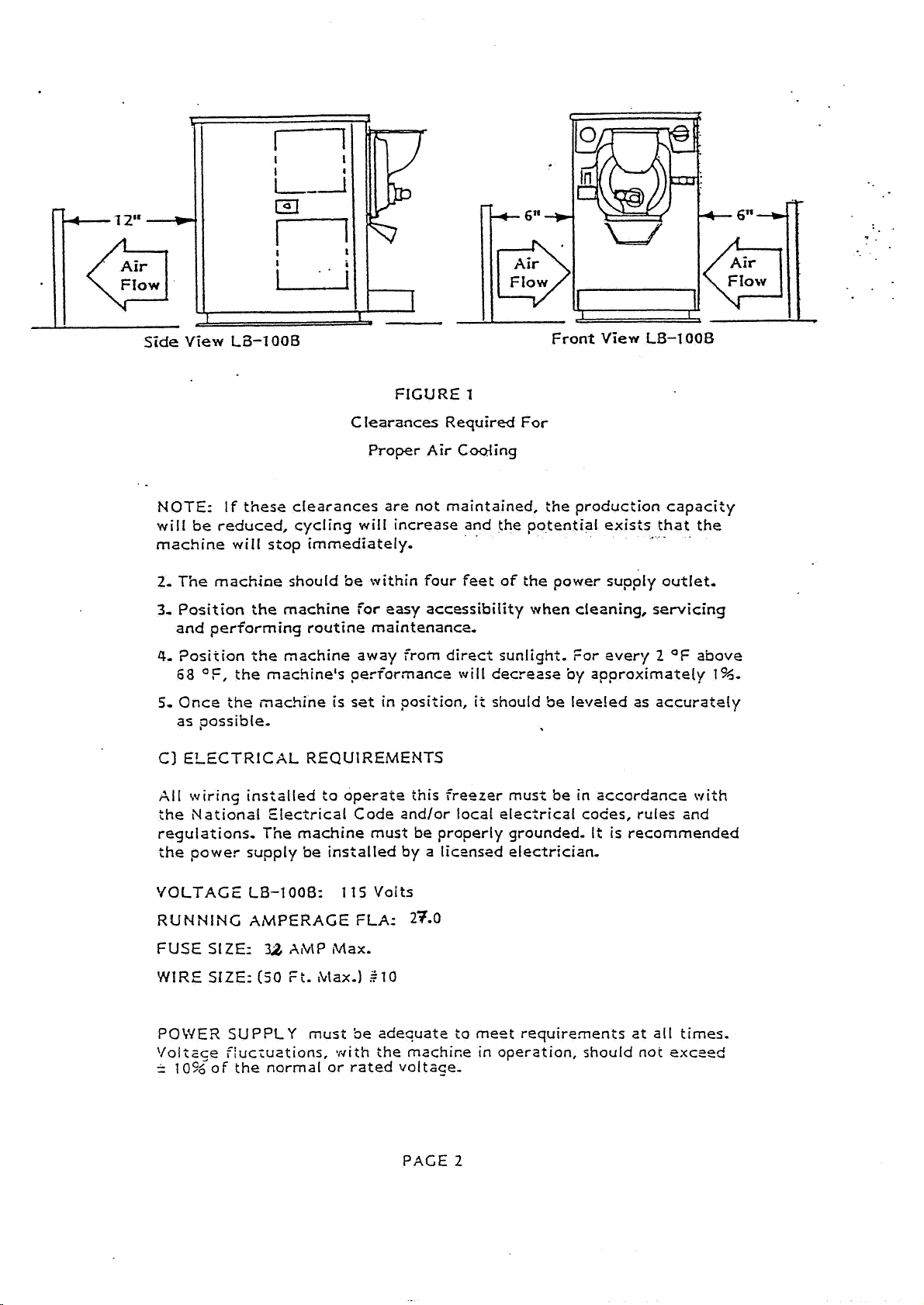
FIGURE
Clearances Required
Proper Air Cooling
NOTE:
will
machine will stop immediately.
2,
The machine should be within four feet of the power supply outlet,
3-
Position the machine
and performing routine maintenance,
4-
68
5-
Once the machine is set in position,
as possible-
C) ELECTRICAL REQUIREMENTS
A11
the National Electrical Code and/or local e1ec;rical codes, rules and
regulations.
the power supply be installed by a licensed electrician.
If
these clearances are not maintained, tile production capacity
be
reduced, cycling will increase and the potential exists that the
for
easy accessibility when cleaning, servicing
2osition the machine away from direct sunlight. for every
F,
the mschine's performance
wiring
installed to operate this freezer must be in accordtnce \vith
The
machine must be properly grounded.
1
For
"
-
2
will
decrease
it
should be le?re!ed as accurately
by
approximately
It
is recommended
OF
above
1
%-
VOLTAGE
RUNNING AMPERAGE
FUSE
WIRE
POWER
V01i~ce f!uc;uations,
=
1
O~~OF
LB-1008:
SIZE:
SIZE:
32
AMP
~Uax.
(50
Fi. 1tlax.1
SUPPLY
the normal or rated voltace-
must 5e adequate to meet
1
15
Volts
FLA:
with
27.0
$10
requirements
ihe machice in operation, should nor exczed
PACE
2
at all times,
fie
mode1
other electrical appliances on the circuit),
rated
.
-
ADEQUATE
This includes the direct power line to the madnine electrical and connection
box,
Coldelite batch Creezers are equipped *:4ith proteciion for the beater motor.
Should the line voltage crop, or
the overioad protector
wiII stop :he machine immediately so that no permanent damage
be caused to the motor.
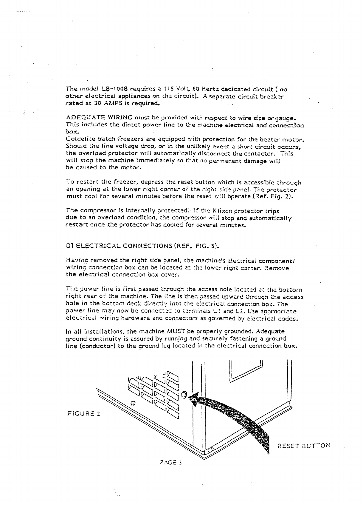
To resiart the freezer, depress the reset button which is accessible throu~h
an opwing at the lower right cornlr of the risnt
must cool for several minutes before the reset will operate (Ref. Fig.
at
LB-1008
30
AMPS
WIRING
requires a
is required
must
be provided with respect to wire size or gauge.
will
automatically disconnect :he contactor. This
11
5
Volt,
60
Hertz
X
in
:he unIikely event a shori circuit occcrs,
dedicated
separate circuit breaker
.
.
circuit [ no
will
sic2
panel. The protector
2).
The compressor is internally protected-
an
due to
restzfl once ihe protector has cooled for several minutes.
01
ELECTRICAL
Haviq removed
wirins c3nnec:ion box ctn be
the itleca-ical connection Sox cover.
-.
I
ne
right :oar of the machine. The tine
hole in the 3ol?om
power iins ,nay now be cannec;td
elec~rical wiring hardware and cocneciors
In all installations, the machine
ground continuity
line (conductor) to
overload condition, the compressor
CONNECTIONS
;he
riskit
side
?ace!,
located
?owe? !ine
is
first ,passed :hroush zhs ac<=si hole iocactd a< the bottom
dack
z'ir=c!:/ ixo
is
assured by runnjng and securely fastening a ground
the
ground lug located in :he electrical connection box,
(REF.
;O
MUST
If
the Xlixon proteGor trips
wil!
stop and auionaiicalIy
FIG.
51,
ih~
machine's t!ec;rica[ cornponencl
az
the
lower righr corner. ?=move
is
?ken ~assed upward thrcugh
:he
c!ec;rical c3r,nec;ion box,
i=rminab
be
Li
and
LZ.
as
governed
properly grounded. Adequate
5y
tkt
Us2
aaproprizce
ele~rical
SCC~~S
The
codes.
UTTO
El
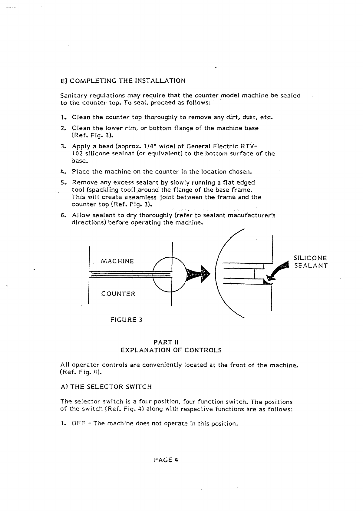
COMPLETING THE INSTALLATION
Sanitary regulations may require that the counter model machine be sealed
to the counter top. To seal, proceed as follows:
1,
Clean the counter top thorougidy to remove any dirt, dust, etc.
2,
Clean the lower rim, or bottom flange of the machine base
(Ref. Fig.
3.
Apply a bead (approx.
102
silicone sealnat (or equivalent) to the bottom surface of the
31.
114"
wide) of General Electric
RTV-
base.
4,
Place the machine on the counter in the location chosen,
5.
Remove any excess sealant by slowly running a flat edged
tool (spackling tool) .around the flange of the base frame.
This
will create asearnless joint between the frame and the
counter top (Ref. Fig.
6.
Allow sealant to dry thoroughly (refer to sealant manufacturer's
3).
directions) before operating the machine.
FIGURE
3
PART
II
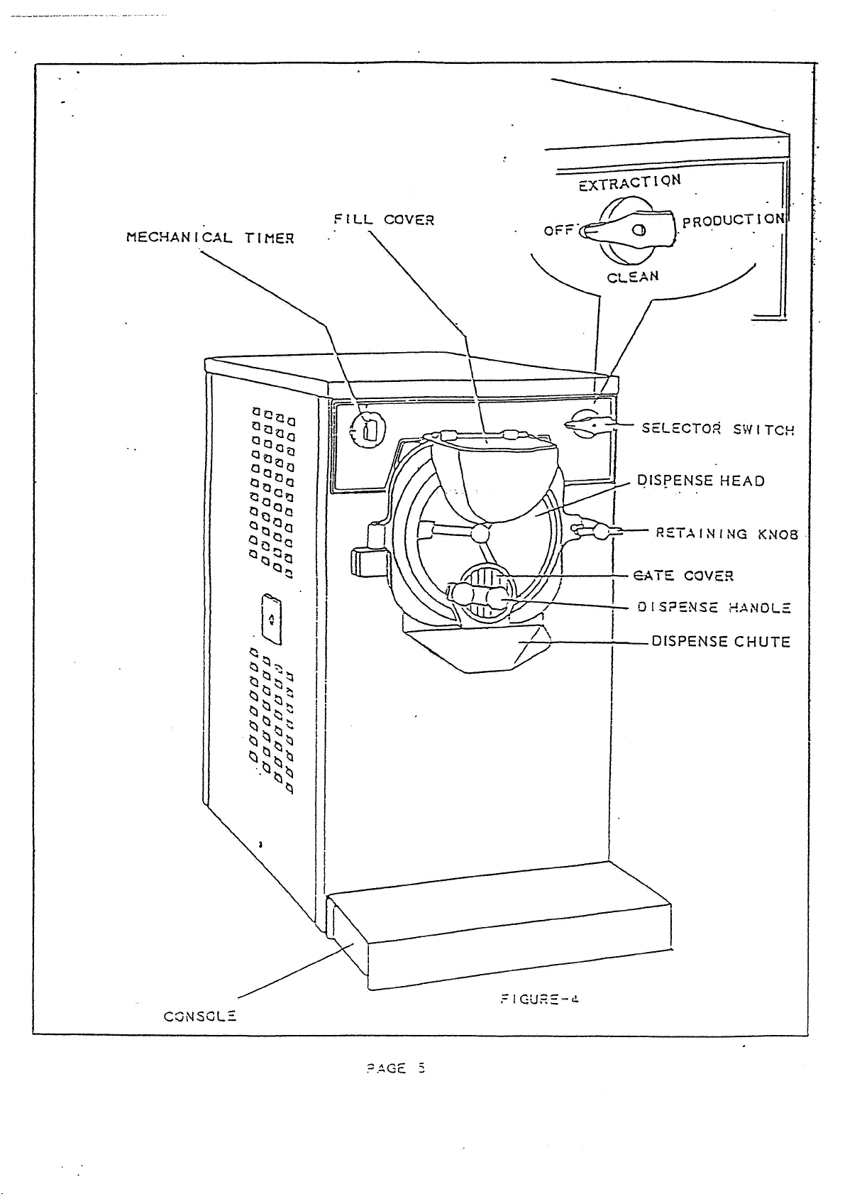
EXPLANATION OF CONTROLS
All operator controls are conveniently located at the front of the machine.
(Ref. Fig.
A)
THE
4).
SELECTOR SWITCH
The selector switch is a four position, four function switch. The positions
of the switch (Ref. Fig.
1,
OFF - The machine does not operate in this position.
$1
along with respective functions are as follows:
SILICONE
SEALANT
PACE
4
 Loading...