

Page 1

Operator’s Manual Verdi™ V-2/V-5/V-6 Diode-Pumped Lasers
5100 Patrick Henry Drive
Santa Clara, CA 95054
Page 2

Verdi V-2/V-5/V-6 Laser Operator’s Manual
This document is copyrighted with all rights reserved. Under the copyright
laws, this document may not be copied in whole or in part or reproduced in
any other media without the express written permission of Coherent, Inc.
Permitted copies must carry the same proprietary and copyright notices as
were affixed to the original. This exception does not allow copies to be
made for others, whether or not sold, but all the material purchased may
be sold, given or loaned to another person. Under the law, copying
includes translation into another language.
Coherent, the Coherent Logo, Verdi, and FAP-I are registered trademarks
of Coherent, Inc.
This product is sold by Coherent pursuant to a limited sublicense under
U.S. Patent No. Re 34,729. The rights which customers of Coherent
receive through purchase of this product are restricted, and exclude any
right to use the product in the telecommunications field.
Every effort has been made to ensure that the data given in this document
is accurate. The information, figures, tables, specifications and schematics
contained herein are subject to change without notice. Coherent makes no
warranty or representation, either expressed or implied with respect to this
document. In no event will Coherent be liable for any direct, indirect,
special, incidental or consequential damages resulting from any defects in
its documentation.
Technical Support
In the US:
Should you experience any difficulties with your laser or need any
technical information, please visit our web site www.Coherent.com
Additional support can be obtained by contacting our Technical Support
Hotline at 800-367-7890 (408-764-4557 outside the U.S.) or E-mail
[email protected]. Telephone coverage is available
Monday through Friday (except U.S. holidays and company shutdowns).
If you call outside our office hours, your call will be taken by our answering
system and will be returned when the office reopens.
If there are technical difficulties with your laser that cannot be resolved by
support mechanisms outlined above, please E-mail or telephone Coherent
Technical Support with a description of the problem and the corrective
steps attempted. When communicating with our Technical Support
Department, via the web or telephone, the model and Laser Head serial
number of your laser system will be required by the Support Engineer
responding to your request.
Outside the U.S.:
If you are located outside the U.S. visit our web site for technical
assistance or contact, by phone, our local Service Representative.
Representative phone numbers and addresses can be found on the
Coherent web site, www.Coherent.com
.
.
Coherent provides telephone and web technical assistance as a service to
its customers and assumes no liability thereby for any injury or damage
that may occur contemporaneous with such services. These support
services do not affect, under any circumstances, the terms of any warranty
agreement between Coherent and the buyer. Operation of any Coherent
laser with any of its interlocks defeated is always at the operator's own risk.
ii
Page 3

Table of Contents
TABLE OF CONTENTS
Preface .................................................................................................................................. ix
U.S. Export Control Laws Compliance ................................................................................ ix
Symbols Used in This Manual and on the Laser System .......................................................x
Section One: Laser Safety .......................................................................................... 1-1
Optical Safety ..................................................................................................................... 1-1
Safety Features and Compliance to Government Requirements ........................................ 1-2
Laser Classification.................................................................................................... 1-2
Protective Housing..................................................................................................... 1-3
Laser Radiation Emission Indicators ......................................................................... 1-3
Beam Attenuator ........................................................................................................ 1-3
Operating Controls..................................................................................................... 1-3
Location of Safety Labels .......................................................................................... 1-3
Electromagnetic Compatibility ........................................................................................... 1-3
Section Two: Description and Specifications.................................................. 2-1
System Description ............................................................................................................. 2-1
Laser Head ................................................................................................................. 2-2
Power Supply............................................................................................................. 2-3
Servo Loops ...................................................................................................... 2-3
Laser Diode Assembly...................................................................................... 2-4
Specifications...................................................................................................................... 2-5
Section Three: Installation......................................................................................... 3-1
Receiving and Inspection.................................................................................................... 3-1
Installation Kit .................................................................................................................... 3-1
Installing the Laser Head .................................................................................................... 3-1
Installing the Power Supply................................................................................................ 3-5
Final Installation and Initial Turn-On Procedures .............................................................. 3-6
External Interlock ............................................................................................................... 3-7
Dimensions ......................................................................................................................... 3-9
Section Four: Operation.............................................................................................. 4-1
Operation ............................................................................................................................ 4-1
Turn-on................................................................................................................................ 4-2
Turn-on (Cold-Start) .................................................................................................. 4-2
LBO Optimization (Optional Step)................................................................... 4-3
Daily Turn-on (Warm-Start) ...................................................................................... 4-3
LBO Optimization (Optional Step)................................................................... 4-4
Turn-off............................................................................................................................... 4-4
Turn-off (Daily Use) .................................................................................................. 4-4
Turn-off (Complete Shut-down)................................................................................ 4-5
Controls, Indicators, and Features ...................................................................................... 4-6
iii
Page 4

Verdi V-2/V-5/V-6 Laser Operator’s Manual
Menu Displays .................................................................................................................. 4-12
System Status Messages .......................................................................................... 4-12
Fault Handling ......................................................................................................... 4-13
Low Power Warning ................................................................................................ 4-14
Section Five: External Computer Control....................................................... 5-1
How to Interface Verdi Lasers ............................................................................................ 5-1
RS-232 Command Language.............................................................................................. 5-1
Instruction Syntax for RS-232 Communication ........................................................ 5-1
ECHO Mode ..................................................................................................... 5-2
PROMPT Mode ................................................................................................ 5-2
?......................................................................................................................... 5-3
= or :.................................................................................................................. 5-3
RS-232 Interface Connection.............................................................................................. 5-3
RS-232 Port Configuration ........................................................................................ 5-3
Setting The Baud Rate ............................................................................................... 5-3
Instruction Set ..................................................................................................................... 5-4
Section Six: Maintenance and Service................................................................ 6-1
Troubleshooting .................................................................................................................. 6-1
FAP-I Replacement ........................................................................................................... 6-22
Preliminary Steps and Data...................................................................................... 6-22
FAP-I Handling Precautions .................................................................................... 6-23
Fiber Cable Handling Precautions ........................................................................... 6-24
FAP-I Removal ........................................................................................................ 6-25
FAP-I Installation ..................................................................................................... 6-27
Fiber Optic Cleaning......................................................................................................... 6-29
Equipment Needed................................................................................................... 6-30
Fiberscope......................................................................................................................... 6-30
Procedure ................................................................................................................. 6-30
Drop and Drag Procedure ............................................................................... 6-30
Cleanroom Swab Procedure............................................................................ 6-33
Alternative Cleaning Procedure...................................................................... 6-35
Examples of Good and Bad Fibers .......................................................................... 6-37
LBO Temperature Optimization ....................................................................................... 6-40
Performing the Optimization ................................................................................... 6-40
LBO Error Message ................................................................................................. 6-41
Fuse Replacement ............................................................................................................. 6-41
Battery Replacement......................................................................................................... 6-42
Preliminary Steps and Data...................................................................................... 6-42
Battery Removal and Installation ............................................................................ 6-43
Battery Charge Circuit Verification ......................................................................... 6-44
Verification of Successful Installation ..................................................................... 6-45
Cleaning the Air Filter ...................................................................................................... 6-45
Criteria for Cleaning ................................................................................................ 6-46
iv
Page 5

Table of Contents
Section Seven: General Operating Principles................................................ 7-1
Laser Head .......................................................................................................................... 7-1
Gain Medium ...................................................................................................................... 7-2
Second Harmonic Generator............................................................................................... 7-2
Temperature Servos ............................................................................................................ 7-3
Output Optics...................................................................................................................... 7-4
Power Monitor .................................................................................................................... 7-4
Shutter................................................................................................................................. 7-4
Heat Sinking ....................................................................................................................... 7-5
Umbilical ............................................................................................................................ 7-5
Power Supply...................................................................................................................... 7-6
Laser Diode......................................................................................................................... 7-6
Battery Backup ................................................................................................................... 7-8
Cooling Issues..................................................................................................................... 7-8
Packing Procedure ......................................................................................................... A-1
Parts List ...............................................................................................................................B-1
Accessories ...........................................................................................................................C-1
Power Meters and Sensors..................................................................................................C-1
Recommendation .......................................................................................................C-1
Warranty .............................................................................................................................. D-1
Responsibilities of the Buyer............................................................................................. D-1
Limitations of Warranty ..................................................................................................... D-1
Glossary ..................................................................................................................... Glossary-1
Index ................................................................................................................................. Index-1
v
Page 6

Verdi V-2/V-5/V-6 Laser Operator’s Manual
LIST OF ILLUSTRATIONS
1-1. Safety Features and Labels .............................................................................................. 1-4
2-1. Verdi V-2/V-5/V-6 Laser System ..................................................................................... 2-1
2-2. Laser Head Optical Schematic......................................................................................... 2-3
3-1. Installation Kit ................................................................................................................. 3-2
3-2. Riser/Heatsink.................................................................................................................. 3-4
3-3. Laser Head Base – Protective Cover Installed................................................................. 3-4
3-4. Laser Head Base – Protective Cover Removed ............................................................... 3-5
3-5. External Interlock ............................................................................................................ 3-7
3-6. Interconnect Diagram ...................................................................................................... 3-8
3-7. Laser Head Dimensions ................................................................................................... 3-9
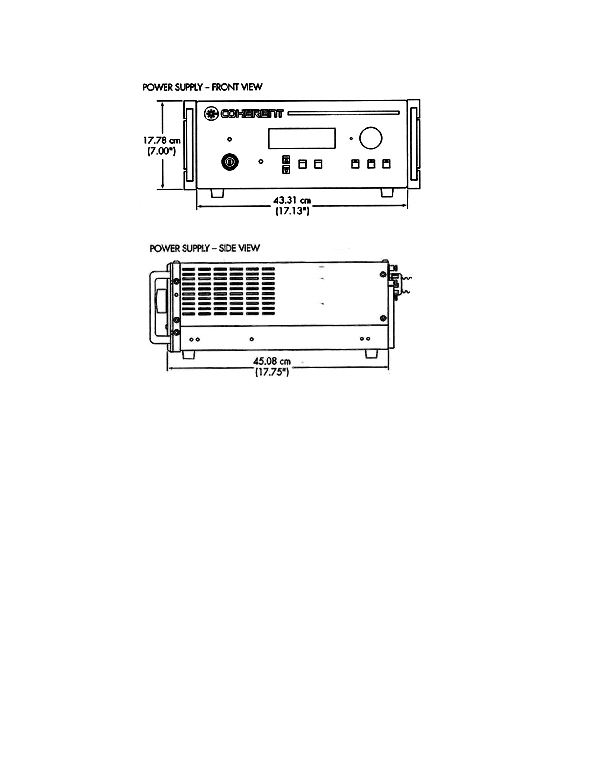
3-8. Power Supply Dimensions............................................................................................. 3-10
4-1. Laser Head Features.........................................................................................................4-6
4-2. Power Supply Front Panel Controls and Indicators......................................................... 4-8
4-3. Power Supply Rear Panel Controls and Indicators........................................................ 4-10
4-4. Menus............................................................................................................................. 4-12
5-1. RS-232 Pin Configuration ............................................................................................... 5-4
6-1. Location of FAP-I Assemblies and Fiber Looping ........................................................ 6-23
6-2. Fiber Optic Covers and FAP-I Anode/Cathode Shorting Clip....................................... 6-24
6-3. FAP-I Assembly Interface.............................................................................................. 6-26
6-4. FAP-I Fiber Optic Connector......................................................................................... 6-27
6-5. Preparation of the Replacement FAP-I Assembly ......................................................... 6-28
6-6. Fiberscope with 20X Eyepiece and SMA Adapter........................................................ 6-31
6-7. Methanol Drop on Lens Tissue...................................................................................... 6-31
6-8. Placement of the Fiber Optic Against the Lens Tissue.................................................. 6-32
6-9. Movement of Fiber Optic Against Lens Tissue............................................................. 6-32
6-10. Methanol Residue .......................................................................................................... 6-33
6-11. Methanol Drop............................................................................................................... 6-34
6-12. Placement and Movement of the Swab Against the Fiber Optic Surface...................... 6-34
6-13. Folded Lens Tissue (Width Wise).................................................................................. 6-35
6-14. Folded Lens Tissue (Lengthwise).................................................................................. 6-35
6-15. Hemostat Attached to Properly Folded Lens Tissue...................................................... 6-36
6-16. Placement and Movement of the Folded Tissue Against the Fiber Optic Surface ........ 6-37
6-17. Good Fiber ..................................................................................................................... 6-38
6-18. Bad or Questionable Fibers............................................................................................ 6-38
6-19. Guidelines for Fiber Optic Inspection ........................................................................... 6-39
6-20. Power Supply Backup Battery....................................................................................... 6-43
6-21. Location of Battery Charge Circuit Resistor, R8........................................................... 6-45
vi
Page 7

Table of Contents
A-1. Packed Verdi V-2/V-5/V-6 Laser Shipping Crate ........................................................... A-2
A-2. Top Foam for Verdi V-2/V-5/V-6 Laser Shipping Crate ................................................. A-3
A-3. Proper Packing of System Umbilical.............................................................................. A-3
A-4. Location of Packed Verdi V-2/V-5/V-6 Laser Maintenance Kit ..................................... A-4
LIST OF TABLES
2-1. Specifications................................................................................................................... 2-5
3-3. Laser System Dimensions................................................................................................ 3-7
3-1. Utility Requirements........................................................................................................3-8
3-2. Environmental Requirements .......................................................................................... 3-9
4-1. Operating States............................................................................................................... 4-1
4-2. Laser Head Features.........................................................................................................4-7
4-3. Power Supply Front Panel Controls and Indicators......................................................... 4-9
4-4. Power Supply Rear Panel Controls and Indicators........................................................ 4-11
4-5. Submenus....................................................................................................................... 4-14
5-1. Response from Laser after Receiving Instruction............................................................ 5-2
5-2. RS-232 Port Description.................................................................................................. 5-3
5-3. RS-232 Commands .......................................................................................................... 5-5
5-4. RS-232 Queries................................................................................................................ 5-6
6-1. Troubleshooting/Fault Messages ..................................................................................... 6-1
6-2. Battery Charge Circuit Voltages .................................................................................... 6-44
A-1. Verdi V-2/V-5/V-6 Laser Shipping Crate Contents......................................................... A-1
vii
Page 8

Verdi V-2/V-5/V-6 Laser Operator’s Manual
LIST OF CHARTS
1. Laser Does Not Start (No Light Output)............................................................................. 6-4
2. Laser Shuts Down (No Light Output)................................................................................. 6-6
3. Laser Output Unstable ........................................................................................................ 6-8
4. AC ON Indicator Does Not Light..................................................................................... 6-10
5. Head Laser Emission Lamp Fault..................................................................................... 6-12
6. External Interlock Fault .................................................................................................... 6-13
7. PS Interlock Fault ............................................................................................................. 6-14
8. LBO Temperature Fault; Vanadate Temperature Fault;
Etalon Temperature Fault; Diode 1 Temperature Fault .................................................... 6-15
9. Baseplate Temperature Fault............................................................................................. 6-16
10. Diode Heat Sink Temperature Fault ................................................................................. 6-17
11. Diode Over Current Fault; Over Current Fault; 10% Current Increase (No Fault).......... 6-18
12. Diode Under Voltage Fault; Diode Over Voltage Fault;
Diode EEPROM Fault; LBO Not Locked at Set Temperature;
Laser Head EEPROM Fault; Power Supply EEPROM Fault;
Power Supply-Head Mismatch Fault; Shutter State Mismatch;
Head-Diode Mismatch Fault............................................................................................. 6-20
13. Battery Requires Service .................................................................................................. 6-21
viii
Page 9
Preface
Preface
This manual contains user information for the Verdi™ V-2/V-5/V-6
Diode-Pumped Lasers.
Read this manual carefully before operating the laser for the
first time. Special attention should be given to the material in
Section One: Laser Safety, which describes the safety features
built into the laser.
Use of controls or adjustments or performance of procedures
other than those specified in this manual may result in
hazardous radiation exposure.
Use of the system in a manner other than that described herein
may impair the protection provided by the system.
U.S. Export Control Laws Compliance
It is the policy of Coherent to comply strictly with U.S. export
control laws.
Export and re-export of lasers manufactured by Coherent are subject
to U.S. Export Administration Regulations, which are administered
by the Commerce Department. In addition, shipments of certain
components are regulated by the State Department under the International Traffic in Arms Regulations.
The applicable restrictions vary depending on the specific product
involved and its destination. In some cases, U.S. law requires that
U.S. Government approval be obtained prior to resale, export or
re-export of certain articles. When there is uncertainty about the
obligations imposed by U.S. law, clarification should be obtained
from Coherent or an appropriate U.S. Government agency.
ix
Page 10
Verdi V-2/V-5/V-6 Laser Operator’s Manual
Symbols Used in This Manual and on the Laser System
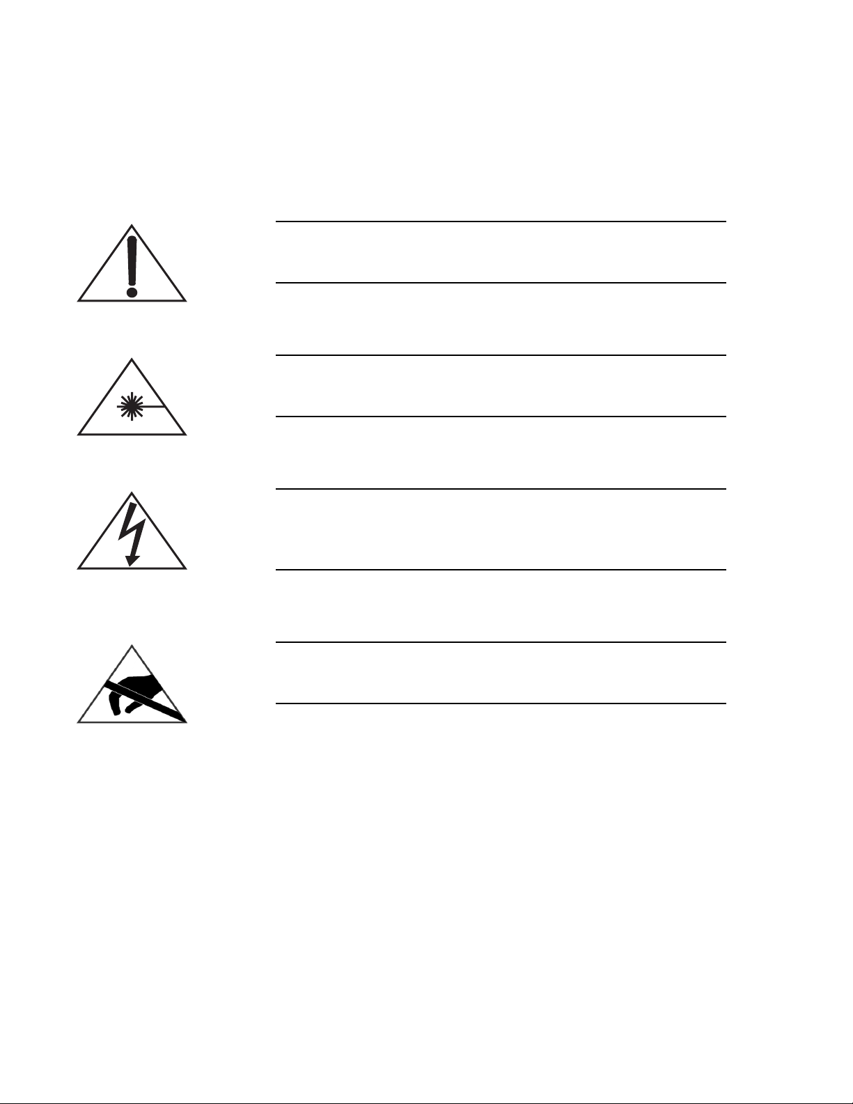
This symbol is intended to alert the operator to the presence of
important operating and maintenance instructions.
This symbol is intended to alert the operator to the danger of
exposure to hazardous visible and invisible laser radiation.
This symbol is intended to alert the operator to the presence of
dangerous voltages within the product enclosure that may be of
sufficient magnitude to constitute a risk of electric shock.
This symbol is intended to alert the operator to the danger of
Electro-Static Discharge (ESD) susceptibility.
x
Page 11

SECTION ONE: LASER SAFETY
Laser Safety
Optical Safety
Laser light, because of its special properties, poses safety hazards
not associated with light from conventional sources. The safe use of
lasers requires that all laser users, and everyone near the laser
system, are aware of the dangers involved. The safe use of the laser
depends upon the user being familiar with the instrument and the
properties of coherent, intense beams of light.
Direct eye contact with the output beam from the laser will cause
serious damage and possible blindness.
The greatest concern when using a laser is eye safety. In addition to
the main beam, there are often many smaller beams present at
various angles near the laser system. These beams are formed by
specular reflections of the main beam at polished surfaces such as
lenses or beamsplitters. While weaker than the main beam, such
beams may still be sufficiently intense to cause eye damage.
Laser beams are powerful enough to burn skin, clothing or paint.
They can ignite volatile substances such as alcohol, gasoline, ether
and other solvents, and can damage light-sensitive elements in video
cameras, photomultipliers and photodiodes. The laser beam can
ignite substances in its path, even at some distance. The beam may
also cause damage if contacted indirectly from reflective surfaces.
For these reasons, and others, the user is advised to follow the
precautions below.
1. Observe all safety precautions in the preinstallation and operator’s manual.
2. Extreme caution should be exercised when using solvents in
the area of the laser.
3. Limit access to the laser to qualified users who are familiar
with laser safety practices and who are aware of the dangers
involved.
4. Never look directly into the laser light source or at scattered
laser light from any reflective surface. Never sight down the
beam into the source.
5. Maintain experimental setups at low heights to prevent inadvertent beam-eye encounter at eye level.
1 - 1
Page 12
Verdi V-2/V-5/V-6 Laser Operator’s Manual
6. As a precaution against accidental exposure to the output beam
or its reflection, those using the system should wear laser
safety glasses as required by the wavelength being generated.
7. Avoid direct exposure to the laser light. The intensity of the
beam can easily cause flesh burns or ignite clothing.
8. Use the laser in an enclosed room. Laser light will remain
collimated over long distances and therefore presents a potential hazard if not confined.
9. Post warning signs in the area of the laser beam to alert those
present.
10. Advise all those using the laser of these precautions. It is good
practice to operate the laser in a room with controlled and
restricted access.
Laser safety glasses can present a hazard as well as a benefit;
while they protect the eye from potentially damaging exposure,
they block light at the laser wavelengths, which prevents the
operator from seeing the beam. Therefore, use extreme caution
even when using safety glasses.
Safety Features and Compliance to Government Requirements
Laser Classification
The following features are incorporated into the instrument to
conform to several government requirements. The applicable United
States Government requirements are contained in 21 CFR,
subchapter J, part II administered by the Center for Devices and
Radiological Health (CDRH). The European Community requirements for product safety are specified in the Low Voltage Directive
(LVD) (published in 73/23/EEC and amended in 93/68/EEC). The
Low Voltage Directive requires that lasers comply with the standard
EN 61010-1 “Safety Requirements For Electrical Equipment For
Measurement, Control and Laboratory Use” and EN60825-1 “Radiation Safety of Laser Products”. Compliance of this laser with the
(LVD) requirements is certified by the CE mark.
The governmental standards and requirements specify that the laser
must be classified according to the output power or energy and the
laser wavelength. The Verdi V-2/V-5/V-6 Lasers are classified as
Class IV based on 21 CFR, subchapter J, part II, section 1040-10 (d).
According to the European Community standards, Verdi
V-2/V-5/V-6 lasers are classified as Class 4 based on EN 60825-1,
clause 9. In this manual, the classification will be referred to as
Class 4.
1 - 2
Page 13

Laser Safety
Protective Housing
Laser Radiation Emission Indicators
Beam Attenuator
Operating Controls
The laser head is enclosed in a protective housing that prevents
human access to radiation in excess of the limits of Class I radiation
as specified in the Federal Register, July 31, 1975, Part II, Section
1040.10 (f) (1) and Table 1-A/EN 60825-1, clause 4.2 except for the
output beam, which is Class IV.
The appropriately labeled lights on both the power supply and the
laser head illuminate approximately 30 seconds before laser emission can occur. Amber lights are used so that they will be seen when
the proper type of safety glasses are used [CFR 1040.10(f)(5)/EN
60825-1, clause 4.6].
A beam attenuator, or shutter, prevents contact with laser radiation
without the need to switch off the laser [CFR 1040.10 (f)(6)/EN
60825-1, clause 4.7].
The laser controls are positioned so that the operator is not exposed
to laser emission while manipulating the controls [CFR
1040.10(f)(7)/EN 60825-1, clause 4.8].
Location of Safety Labels
Electromagnetic Compatibility
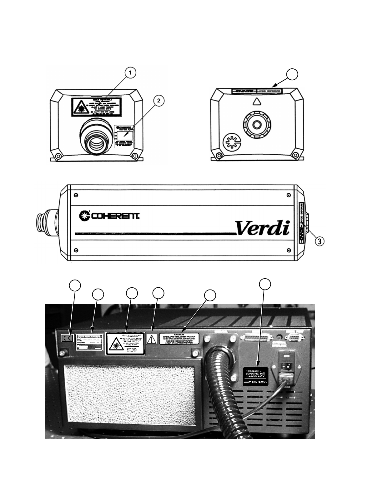
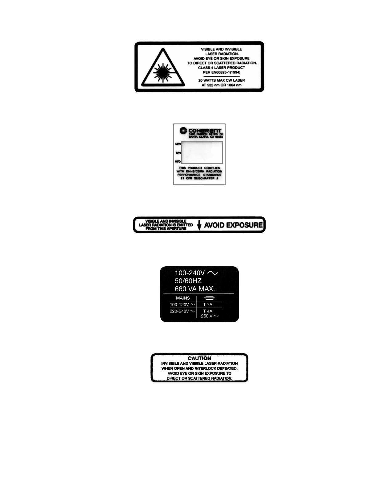
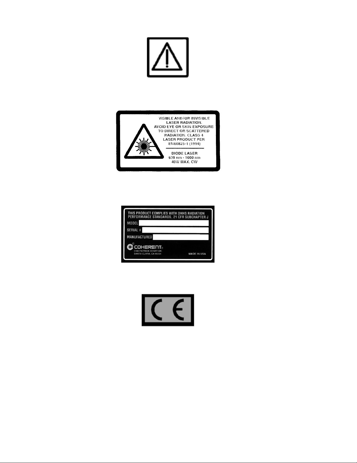
Refer to Figure 1-1 for a description and location of all safety labels.
These include warning labels indicating removable or displaceable
protective housings, apertures through which laser radiation is
emitted and labels of certification and identification [CFR
1040.10(g), CFR 1040.2, and CFR 1010.3/ EN60825-1, Clause 5]].
The European requirements for Electromagnetic Compliance
(EMC) are specified in the EMC Directive (published in
89/336/EEC).
Conformance (EMC) is achieved through compliance with the
harmonized standards EN55011 (1991) for emission and
ENC50082-1 (1992) for immunity.
The laser meets the emission requirements for Class B, group 1 as
specified in EN55011 (1991).
Compliance of this laser with the (EMC) requirements is certified by
the CE mark.
1 - 3
Page 14
Verdi V-2/V-5/V-6 Laser Operator’s Manual
LASER HEAD
REAR VIEW FRONT VIEW
3
TOP VIEW
POWER SUPPLY
9
8
7
6
5
4
Figure 1-1. Safety Features and Labels (Sheet 1 of 3)
1 - 4
Page 15
1.
2.
Laser Safety
3.
4.
5.
Figure 1-1. Safety Features and Labels (Sheet 2 of 3)
1 - 5
Page 16
Verdi V-2/V-5/V-6 Laser Operator’s Manual
6.
7.
8.
9.
Figure 1-1. Safety Features and Labels (Sheet 3 of 3)
1 - 6
Page 17
Description and Specifications
SECTION TWO: DESCRIPTION AND SPECIFICATIONS
System Description
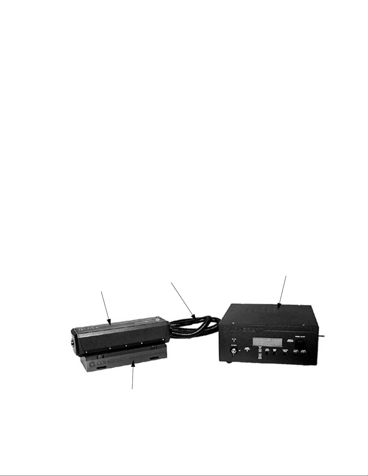
The Verdi V-2/V-5/V-6 laser system (Figure 2-1) is a compact
solid-state diode-pumped, frequency-doubled Nd:Vanadate
(Nd:YVO4) laser that provides single-frequency green (532 nm)
output at power levels greater than 2 Watts/5 Watts/6 Watts. Single
frequency operation results in lower noise in the green output.
The Verdi V-2/V-5/V-6 laser consists of the laser head and power
supply connected by an umbilical. The umbilical contains a fiber
optic cable to transmit light from the diode bar in the power supply
to the laser head. It also houses electrical cables that provide control
and monitoring signals between the laser head and power supply.
The Verdi V-2/V-5/V-6 laser consists of the laser head and power
supply connected by an umbilical. The umbilical contains a fiber
optic cable to transmit light from the diode bar in the power supply
to the laser head. It also houses electrical cables that provide control
and monitoring signals between the laser head and power supply.
The laser head is shown mounted on a riser/heat sink. The riser/heat
sink can be the passive version or the water cooled version
depending on the operating environment.
LASER HEAD
RISER / HEAT SINK
UMBILICAL
Figure 2-1. Verdi V-2/V-5/V-6 Laser System
POWER SUPPLY
2 - 1
Page 18

Verdi V-2/V-5/V-6 Laser Operator’s Manual
The passive riser/heat sink alone does not possess sufficient mass
to maintain the laser head base below 55°C and accordingly
should be mounted on a thermally conductive surface as
described in the installation section.
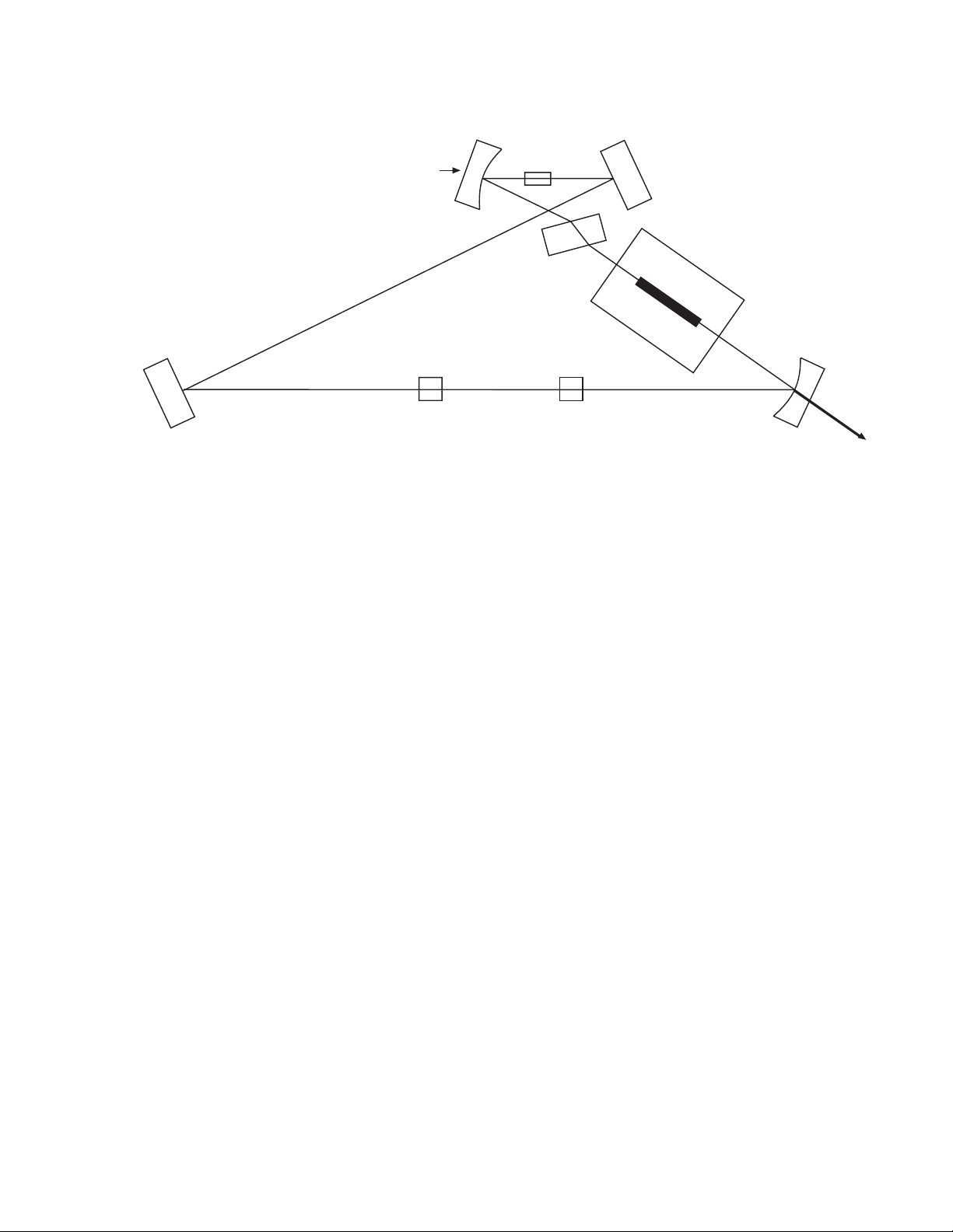
Laser Head
The major optical elements are in a hermetically sealed head and
includes:
• Vanadate as the gain medium
• LBO as the frequency doubling crystal
• An etalon as the single-frequency optic
• Optical diode
• Astigmatic compensator and three cavity mirrors
All optical components are mounted on proprietary Super Invar for
strength and stability.
The temperature of the Vanadate and etalon are controlled by
thermo-electric coolers (TECs), which are capable of heating or
cooling the optical element. The temperature of the lithium triborate
(doubling generator, or LBO), is controlled by a resistive heater.
Accumulated heat in the laser head is dissipated by an optional
riser/heat sink mounted on the laser head baseplate. Baseplate
temperature is monitored by a CPU in the power supply, which will
shut the system down if the laser head temperature reaches 55°C.
The laser head utilizes a Neodymium Vanadate (Nd:YVO4) crystal
with the pump power provided by fiber delivery.
The nonlinear medium is a Type I, non-critically phase matched
LBO crystal held at approximately 150°C. Unidirectional operation
is achieved using an optical diode. Since the laser is a unidirectional,
homogeneously broadened system, it tends to naturally run single
frequency, with the etalon reinforcing this behavior.
2 - 2
Page 19
Description and Specifications
Power Supply
Nd:YVO
Pump
Astigmatic
Compensator
Etalon
4
Optical
Diode
Figure 2-2. Laser Head Optical Schematic
The main functions of the power supply include:
LBO
Green
Output
• Supplying DC power for the laser diode system that pumps the
gain medium in the laser head
• Controlling six servo loops
• Cooling for the laser diode assemblies
• Controlling and monitoring the laser output
• Storing data
• Providing a user interface.
Servo Loops The CPU controlled servo loops are briefly described below. See
“Temperature Servos” on page 7-3 for additional information.
Light loop – A photodiode in the laser head monitors the laser
output. The CPU controls the output power from the Verdi laser
based on the photodiode and in conjunction with the requested
power from the power supply front panel. The CPU achieves this
control by adjusting the diode pump power to the Vanadate.
• LBO temperature – The LBO doubling crystal is held at
approximately 148°C by a resistive heater. To prevent rapid
change of temperature that may cause LBO crystal damage
during warm-up, the CPU regulates a slow ramp-up to operating temperature. This typically lasts fewer than 30 minutes.
2 - 3
Page 20

Verdi V-2/V-5/V-6 Laser Operator’s Manual
In case of loss of AC power (due to a power failure or inadvertantly turning off the rear panel power switch), the laser is
equipped with a battery powered, CPU-controlled, cool-down
feature. This feature lowers the LBO temperature gradually to
room temperature.
• Diode temperature – Diode operating temperature is held
constant by the TEC’s. Excess heat is dissipated by forced air
cooling through heat sinks. The diode heat sinks are located
within the power supply.
• Vanadate and etalon temperature – These optical components
are maintained at preset levels by TECs.
Laser Diode Assembly
One laser diode assembly is located in the power supply. This
assembly is controlled and monitored by the CPU. The FAP-I™
(fiber array package- integrated) assembly houses a diode bar and a
TEC.
See “Laser Diode” on page 7-6 for additional information on the
laser diode assemblies.
2 - 4
Page 21
Description and Specifications
Specifications
Specifications for the Verdi V-2/V-5/V-6 lasers are listed in
Table 2-1.
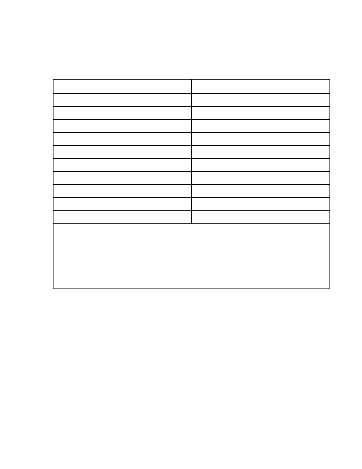
Table 2-1. Specifications
PARAMETER SPECIFICATION
Output Power 2, 5, or 6 W
Wavelength 532 nm
[5]
[1]
[3]
[2]
2.25 mm ± 10%
< 0.5 mrad
<1.1
±1%
< 0.02% rms
< 5 MHz rms
Beam Diameter
Beam Divergence
2
M
Power Stability
[4]
Noise
Polarization > 100:1, vertical, linear
Linewidth
Pointing Stability
All specifications are subject to change without notice.
[1] 1/e
[2] Full-angle divergence.
[3] Measured over 2 hours after a 15 minute warm-up.
[4] Measured from 10 Hz to 1 GHz.
[5] Measured over 50 msec with a thermally stabilized reference etalon.
[6] 25°C to 35°C temperature change.
2
at exit port.
[6]
<2 µrad/°C
2 - 5
Page 22

Verdi V-2/V-5/V-6 Laser Operator’s Manual
2 - 6
Page 23

SECTION THREE: INSTALLATION
Installation
Receiving and Inspection
Installation Kit
Inspect shipping containers for signs of rough handling or damage.
Indicate any such signs on the bill of lading. Report any damage
immediately to the shipping carrier, and to Coherent Order Administration Department (800-438-6323) or to an authorized Coherent
representative.
Retain shipping containers. The containers will be required if
the system is returned to the factory for service. The containers
may also be needed to support a shipping damage claim.
Coherent recommends that three people unpack and transport the
Verdi V-2/V-5/V-6. The power supply weighs70 pounds and should
be lifted by two people while the laser head, which weighs 22.2
pounds, can be lifted by the third person. The laser head and power
supply are connected by the umbilical.
The installation kit contains the necessary hardware for Verdi installation. See Figure 3-1 for details.
Installing the Laser Head
The laser head is shipped with either a passive or a water-cooled
riser/heat sink. This riser/heat sink maintains the Verdi output beam
at a suitable height for pumping a laser such as the Coherent Mira.
A passive riser/heat sink when mounted on a thermally conductive
surface (such as an optical table) provides sufficient heat dissipation
for the laser head under normal ambient conditions. The temperature
of the laser head baseplate is monitored by the Verdi power supply
and can be displayed on the power supply front panel. Power dissipation through the baseplate is typically 20 to 25 Watts (30 Watts
maximum). The Verdi will shut down if the baseplate temperature
exceeds 55°C.
An optional water-cooled riser/heat sink is available for use with a
chiller.
The laser head is shipped with a protective plastic plate installed
over the baseplate. Leave the plastic plate in place until laser head is
ready for installation.
3 - 1
Page 24
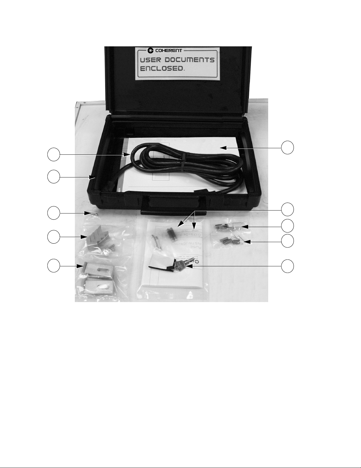
Verdi V-2/V-5/V-6 Laser Operator’s Manual
3
5
2
10
9
1
1. Riser/heat sink installation hardware
2. Operator’s manual
3. AC power cord
4. Power supply key
5. Installation kit case
7
6
8
4
6. Interlock-disassembled
7. Fuses and instructions
8. FAP-I installation hardware, including shorting clips,
end caps, etc.
9. Laser head/heat sink mounting hardware
10. Dowel pins – laser head/heat sink
Figure 3-1. Installation Kit
1. Remove the packing material from the riser/heat sink
(Figure 3-2).
2. Insert two dowel pins (Figure 3-1 , item 12) into the riser/heat
sink dowel holes (Figure 3-2, item 1), ball-end up.
3 - 2
Page 25
Installation
Avoid damage to the laser head baseplate, which is milled to a
flatness of ± 0.1 mm. This tolerance provides maximum thermal
conduction between the baseplate and the mounting surface.
Keep the umbilical as straight as possible while avoiding
rotating the laser head with respect to the power supply.
Do not apply thermal compound or any other material on the
laser head baseplate or on the riser/heat sink.
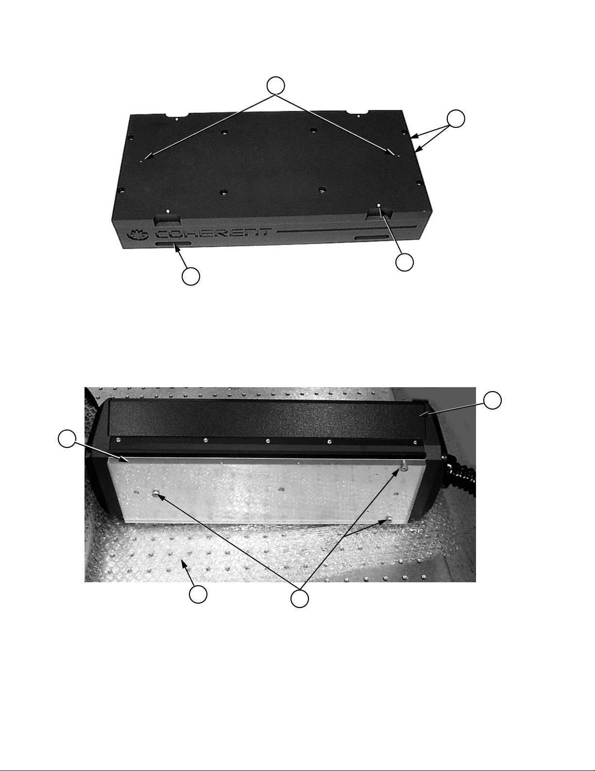
3. Remove the laser head and power supply from the shipping
crate. Place the laser head on its side and on a protected surface
to avoid scratching the cover as shown on Figure 3-3. Remove
the three screws (Figure 3-3, item 2) securing the protective
plastic cover (item 4) to the laser head baseplate. Any
scratches, damage, or contamination of the baseplate will
reduce the thermal conduction between the baseplate and the
mounting surface.
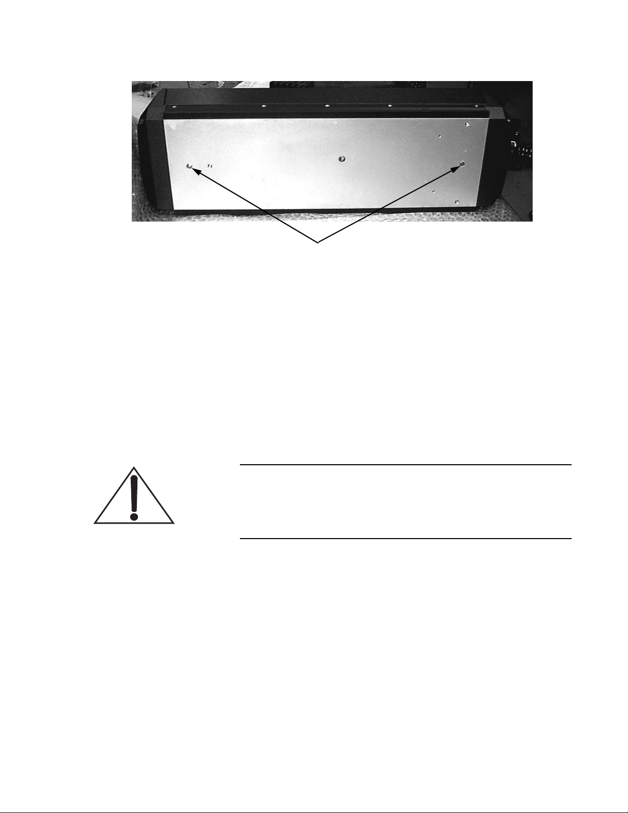
4. Refer to Figure 3-4 for the laser head dowel pin positions.
Carefully place the laser head over the riser/heat sink and onto
the dowel pins.
Do not use excessive force when clamping the Verdi to the
riser/heat sink.
5. Use four laser head clamps (Figure 3-1 item 9) to secure the
laser head to the riser/heat sink as shown in Figure 4-1 on
page 4-6. Tighten the 4 clamps firmly using an Allen head
wrench.
6. Proceed to the paragraph titled, “Installing the Power Supply”.
The riser/heat sink clamps and chiller connection will be
installed during the final installation procedures.
3 - 3
Page 26
Verdi V-2/V-5/V-6 Laser Operator’s Manual
4
1
2
3
1. Dowel holes (2)
2. Cooling water inlet and outlet (if included)
Figure 3-2. Riser/Heatsink
4
3. Laser head clamp screw holes (4)
4. Optical table clamp mounts (4)
1
3
1. Laser head
2. Protective plastic cover retaining screws (3)
Figure 3-3. Laser Head Base – Protective Cover Installed
2
3. Protective material
4. Protective plastic cover
3 - 4
Page 27
DOWEL PIN HOLES
Figure 3-4. Laser Head Base – Protective Cover Removed
Installation
Installing the Power Supply
1. Move the power supply to an accessible-friendly location,
preferably away from heat producing sources. Ensure the
cooling intake and exhaust (rear, top, and left side) are not
blocked or obstructed.
If storing the power supply in a 19 in. (48 cm) equipment rack,
allow a minimum horizontal clearance of 17.937 in.
(45.56 cm) for the front panel of the power supply.
The system will not operate with the interlock open. For additional information on the interlock, including the connection of
an external interlock circuit, refer to the paragraph titled,
“External Interlock”.
2. Connect the interlock connector (Figure 3-1, item 6) on the
rear of the power supply in the location shown in Figure 4-3 on
page 4-10.
The interlock connector may be located in the installation kit
or may be attached to the umbilical.
3. Connect the AC power cord on the rear of the power supply in
the location shown in Figure 4-3 on page 4-10. Do not connect
the AC power cord at this time.
Each customer must inspect the power cord and install the
proper connector if necessary. The connector should be
installed in a properly grounded outlet with a maximum of
3 - 5
Page 28
Verdi V-2/V-5/V-6 Laser Operator’s Manual
10 Ampere service @ 110 V and 11 Ampere service @ 220 V
for proper overcurrent and earth fault protection.
4. Proceed to the paragraph titled, “Final Installation and Initial
Turn-On Procedures”.
Final Installation and Initial Turn-On Procedures
After installing the laser head and power supply in accordance with
paragraphs titled, “Installing the Laser Head” and “Installing the
Power Supply”, complete the installation as follows:
1. Position the power supply and laser head in the operating position with the umbilical as straight as possible. Ensure that the
umbilical has a bend radius of 5 inches or greater. A distance
of 6 to 24 inches is recommended between the Verdi output
and any laser being pumped.
Excessively tight umbilical bends (less than a 5 inch radius) can
cause permanent damage to the optical fiber.
2. If a water-cooled system is used, position the chiller in the
operating position. Fill and prepare the chiller in accordance
with the chiller user’s manual.
3. Cut the user-supplied cooling water lines to the appropriate
lengths and use the water line hardware (Figure 3-1, item 9) to
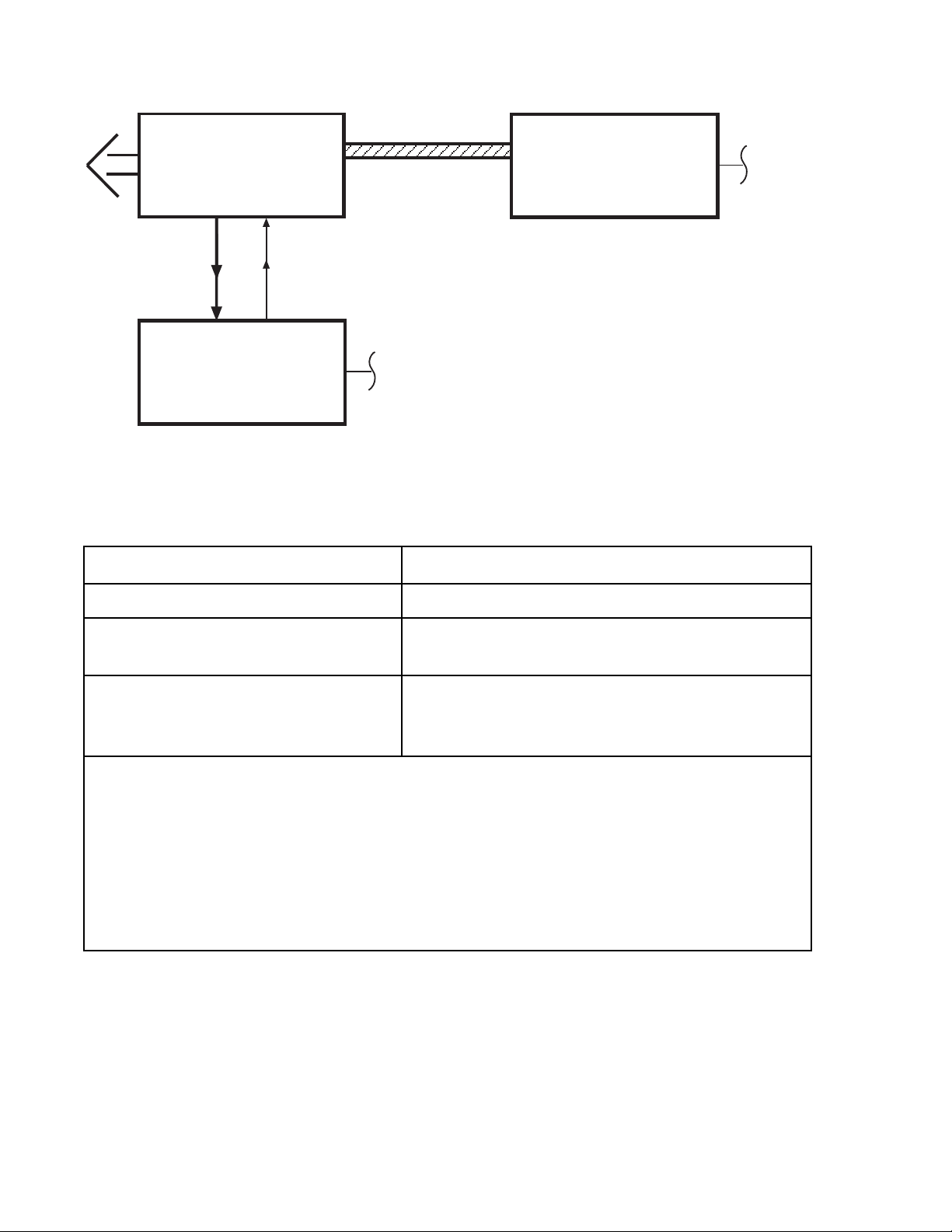
connect the riser/heat sink to the chiller (Figure 3-6). Apply
teflon tape to the hardware threads and install the washers from
the installation kit over the threads when connecting the stainless steel ferrule to the riser/heat sink. Check the system for
leaks.
4. If a passive riser/heat sink will be used, ensure the riser/heat
sink is mounted on a thermally conductive surface (such as an
optical table) that provides sufficient heat dissipation to maintain the laser head baseplate below 55°C, preferably below
40°C.
5. Use four riser/heat sink clamps (Figure 3-1, item 1) to secure
the system to the optical table as shown in Figure 4-1 on
page 4-6. Tighten the two front clamps firmly using an Allen
head wrench. Tighten the two rear clamps finger tight only.
6. Connect power supply to facility power. Ensure all packing
materials have been removed.
7. Perform the procedure in paragraph titled, “Turn-on
(Cold-Start)” on page 4-2.
3 - 6
Page 29

Installation
External Interlock
The system will not operate with the interlock open. An interlock
connector is located on the power supply rear panel. The interlock
status is monitored by the CPU. If the interlock is open, the message,
“External Interlock Fault” will be displayed on the power supply
front panel.
An external interlock circuit can be connected to the laser system
and wired to a door switch to provide additional operating safety.
When the door is opened, the laser will shut down. Press MENU
EXIT key to clear the fault and continue operation.
To incorporate an external safety interlock circuit into the laser
system, perform the following steps:
1. Turn off the laser system. Locate and remove the Interlock
connector from the back of the Verdi power supply. This type
of connector is called a “three pin mini-DIN”.
2. Slide the plastic cover off of the connector. Locate the two pins
that have a wire soldered between them. These are pins 1 and
2. Remove the shorting wire and solder your interlock wires to
these two pins. Make sure the wires have adequate strain relief.
3. Solder the other ends of the wires to an interlock switch. You
can use many types of switches. The switch must be of a type
that has its contacts closed when it is safe to operate the laser
and open when it is not safe.
4. Figure 3-5 shows the wiring diagram for the switch. One wire
runs from pin 1 of the connector to the normally open contact
of the switch. The other wire runs from pin 2 to the common
terminal of the switch. The switch is shown in the open position. This is the condition in which you do not want the laser
beam to operate.
Figure 3-5. External Interlock
5. The interlock circuit in Verdi operates from a +/-12 VDC
circuit. Its current is limited to around 1 mA. For these ratings,
a “dry-circuit” type switch will give the most reliable operation.
3 - 7
Page 30
Verdi V-2/V-5/V-6 Laser Operator’s Manual
UMBILICAL
LASER HEAD
WATER LINES (if using Water Cooling)
AIR COOLED
POWER SUPPLY
FACILITY
POWER
CHILLER
FACILITY
POWER
Figure 3-6. Interconnect Diagram
Table 3-1. Utility Requirements
PARAMETER REQUIREMENT
Power Requirements 100 to 240 VAC
Maximum Current 6.5 Amps @ 100 VAC
7 Amps @ 220 VAC
Cooling:
Laser head:
Power supply:
Note: All specifications and requirements are subject to change without notice.
[1] The power supply is autoranging and will accommodate the full range of input voltages without hardware
changes.
[2] The electrical service should have a main power disconnect switch located in close proximity to the laser. The
main power disconnect switch shall be clearly marked as the disconnecting device for the laser, and shall be
within easy reach of the operator.
[3] The passive riser/heat sink must be mounted on a conductive surface capable of maintaining the laser head base-
plate at less than 55°C. An optional riser/heat sink and chiller or chill plate can also be used. Refer to the paragraph titled, Installing the Laser Head, for additional information on removing waste heat from the laser head.
Riser/heat sink
Air-cooled with ambient air
[1][2]
[3]
3 - 8
Page 31
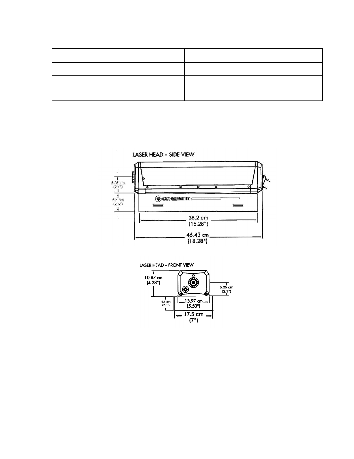
Table 3-2. Environmental Requirements
PARAMETER REQUIREMENT
Operating temperature 15 to 35°C (59 to 95°F)
Relative humidity 5 to 95% (non condensing)
Altitude Sea level to 10,000 feet
Installation
Dimensions
Figure 3-7. Laser Head Dimensions
3 - 9
Page 32
Verdi V-2/V-5/V-6 Laser Operator’s Manual
Figure 3-8. Power Supply Dimensions
3 - 10
Page 33
SECTION FOUR: OPERATION
Operation
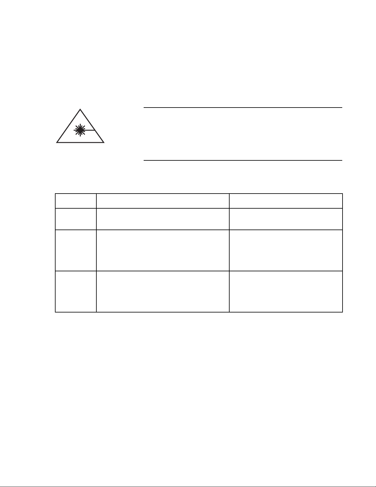
Wear laser safety glasses to protect against the radiation generated from the laser. It is assumed that the operator has read
Section One: Laser Safety, and is familiar with laser safety practices and the dangers involved. Ensure all personnel in the area
are wearing laser safety glasses.
Table 4-1. Operating States
STATE SWITCH POSITION STATUS
Operation
OFF
STANDBY
ON
• Power Switch (rear panel): OFF.
• All other switches: Any position.
• Power Switch (rear panel): ON.
• Keyswitch: STANDBY.
• Power Switch (rear panel): ON.
• Keyswitch: ON.
All functions off (except LBO CPU
until cool-down is complete).
Laser diode off.
Vanadate temperature servo on.
LBO temperature servo on.
Etalon temperature servo on.
Laser diode on.
Vanadate temperature servo on.
LBO temperature servo on.
Etalon temperature servo on.
4 - 1
Page 34

Verdi V-2/V-5/V-6 Laser Operator’s Manual
Turn-on
Ensure the keyswitch is in the STANDBY position prior to
performing the “Cold Start” Turn-on procedure. Turning the
keyswitch to the ON position will result with the fault “LBO Not
Locked at Set Temp” displayed until the LBO reaches operational temperature.
Turn-on (Cold-Start)
The cold-start procedure should be used when the Verdi V-2/V-5/V-6
power supply rear panel power switch has been off for longer than
30 minutes (laser in the OFF state as described in Table 4-1). In this
condition, all servos are off and the Verdi has to stabilize the servos
which can take up to 30 minutes. During this time, the laser diode
cannot be turned on.
See the paragraph titled, “Second Harmonic Generator” on page 7-2
for additional information on the LBO heater ramp-up and stabilization.
Cold-start can also be accomplished when the laser is externally
controlled by a computer. Refer to Table 5-3 on page 5-5 and
Table 5-4 on page 5-6 for a list of RS-232 commands and queries.
Use the following procedure to perform a cold-start of the system.
1. Ensure the keyswitch is in the STANDBY position.
2. Set the power switch on the power supply rear panel to “on.”
The AC power and LASER EMISSION indicators will light.
(See Table 6-1 on page 6-1 if an indicator does not light.) The
power supply display will then indicate “System warming up”.
Refer to Figure 4-4 on page 4-12 for the front panel displays
1
and menus
.
3. Turn on the chiller. Verify there are no cooling line connection
leaks at the Verdi riser/heat sink, and at the chiller.
4. Verify the chiller water temperature is set to approximately
20°C. Adjust the temperature setpoint as required.
5. Set the output power to the desired level using the POWER
ADJUST knob. The output power can be adjusted to 0.01 watts
to facilitate beam alignment.
1. Although the Verdi laser system will display zero operating hours, please note that the system was turned on and
operated as part of our thorough manufacturing and final test procedures.
4 - 2
Page 35

Operation
6. Allow 30 minutes for the heaters and thermo-electric coolers
(TECs) to achieve operating temperature. The status of all
servos can be viewed by scrolling to the Servo Status screen.
Once this process is complete, the display will indicate
“Standby”. The system is now ready for key on.
Ensure the laser output is blocked or directed at an intended
target. Ensure all personnel in the area are wearing laser safety
glasses.
7. Open the shutter by pressing the SHUTTER OPEN pushbutton
on the power supply front panel.
8. Laser light will emit from the laser head after the current
ramp-up.
Coherent strongly recommends a weekly log book of diode current
(read from front screen) vs. output power level is maintained. Such
a record would prove to be very useful in troubleshooting.
LBO Optimization (Optional Step)
Daily Turn-on (Warm-Start)
If diode current increases 10% or more over the initial installation
value (or current baseline value) to achieve the same output power,
use the LBO Optimization menu shown in Table 4-5 on page 4-14 to
access the LBO optimization routine. See the paragraph titled,
“LBO Temperature Optimization” on page 6-40 for details on the
LBO optimization procedure.
A warm-start can be performed when the Verdi power supply rear
panel power switch has been on for more than 30 minutes (laser in
standby as described in Table 4-1).
The recommended daily operation of the Verdi is to use this
warm-start turn-on procedure in conjunction with the turn-off procedure that leaves the rear panel power switch in the “on” state.
If the power supply has been off for longer than 30 minutes (AC ON
indicator not lit), perform the procedure in paragraph titled,
“Turn-on (Cold-Start)”.
Warm-start can also be performed when the laser is externally
controlled by a computer. Refer to Table 5-3 on page 5-5 and
Table 5-4 on page 5-6 for a list of RS-232 commands and queries.
4 - 3
Page 36

Verdi V-2/V-5/V-6 Laser Operator’s Manual
Use the following procedure to perform a warm-start of the system.
1. Verify there are no cooling line leaks at the Verdi riser/heat
sink and at the chiller. Verify the chiller water temperature is
set to 20°C. Adjust the setpoint temperature as required.
2. The LASER EMISSION indicator should be on. If the indicator is not on, refer to Table 6-1 on page 6-1. Turn the
keyswitch on the power supply front panel to ON.
3. Once the keyswitch is in the ON position, the Main Display
will appear on the power supply front panel display. Refer to
Figure 4-4 on page 4-12 for a list of the display menus.
Ensure the laser output is blocked or is directed at an intended
target. Ensure all personnel in the area are wearing laser safety
glasses.
LBO Optimization (Optional Step)
Turn-off
4. Laser light will emit from the laser head after current ramp-up.
5. Open the shutter by pressing the SHUTTER OPEN pushbutton
on the power supply front panel.
6. If necessary, adjust the POWER ADJUST knob for the desired
output power level. The output power can be adjusted to
0.01 watts to facilitate beam alignment.
Coherent strongly recommends a weekly log book of diode current
(read from front screen) vs. output power level is maintained. Such
a record would prove to be very useful in troubleshooting.
If diode current increases 10% or more over the initial installation
value (or current baseline value) to achieve the same output power,
use the LBO Optimization menu shown in Table 4-5 on page 4-14 to
access the LBO optimization routine. See the paragraph titled,
“LBO Temperature Optimization” on page 6-40 for details on the
LBO optimization procedure.
Turn-off (Daily Use)
When the Verdi is being used on a daily basis, turn-off consists of
turning the keyswitch to the STANDBY position. This shuts off the
laser diodes and places the Verdi in standby as described in Table 4-1
on page 4-1. This method avoids the heater ramp-up cycle described
above in the paragraph titled, “Turn-on (Cold-Start)”.
4 - 4
Page 37
Operation
Do not turn the power switch on the power supply rear panel to
the OFF position. If all power is to be removed from the system,
perform the procedure in paragraph titled, “Turn-off (Complete
Shut-down)”.
Turn-off daily use can also be performed when the laser is externally
controlled by a computer. Refer to Table 5-3 on page 5-5 and
Table 5-4 on page 5-6 for a list of RS-232 commands and queries.
Turn-off (Complete Shut-down)
This procedure will remove all power from the Verdi and is recommended for performing system maintenance or if no operation is
anticipated for extended periods of time. Use the cold-start procedure to turn the Verdi back on after a complete shut-down.
Complete shut-down can also be performed when the laser is externally controlled by a computer. Refer to Table 5-3 on page 5-5 and
Table 5-4 on page 5-6 for a list of RS-232 commands and queries.
1. Turn the keyswitch power supply front panel to STANDBY.
2. Access and select the LBO Settings submenu. Press the
MENU SELECT pushbutton to start the LBO cool-down
cycle.
To avoid unnecessary use of the backup battery, do not turn the
power switch on the power supply rear panel to the OFF position while the Verdi is in the cool-down cycle. This takes approximately 30 minutes.
3. During the cool-down cycle, the LBO temperature can be
monitored from the main screen or the LBO Settings submenu.
When the LBO temperature decreases below 40°C, turn the
AC power switch on the power supply rear panel to the OFF
position.
Removing AC power from the power supply will cause the
internal battery to complete the LBO cool-down cycle. This
causes unnecessary drain on the battery. For maximum battery
life, use the LBO cool down menu. Refer to the paragraph
titled, “Battery Backup” on page 7-8 for more information.
4. Turn off the chiller if equipped with the system.
4 - 5
Page 38
Verdi V-2/V-5/V-6 Laser Operator’s Manual
Controls, Indicators, and Features
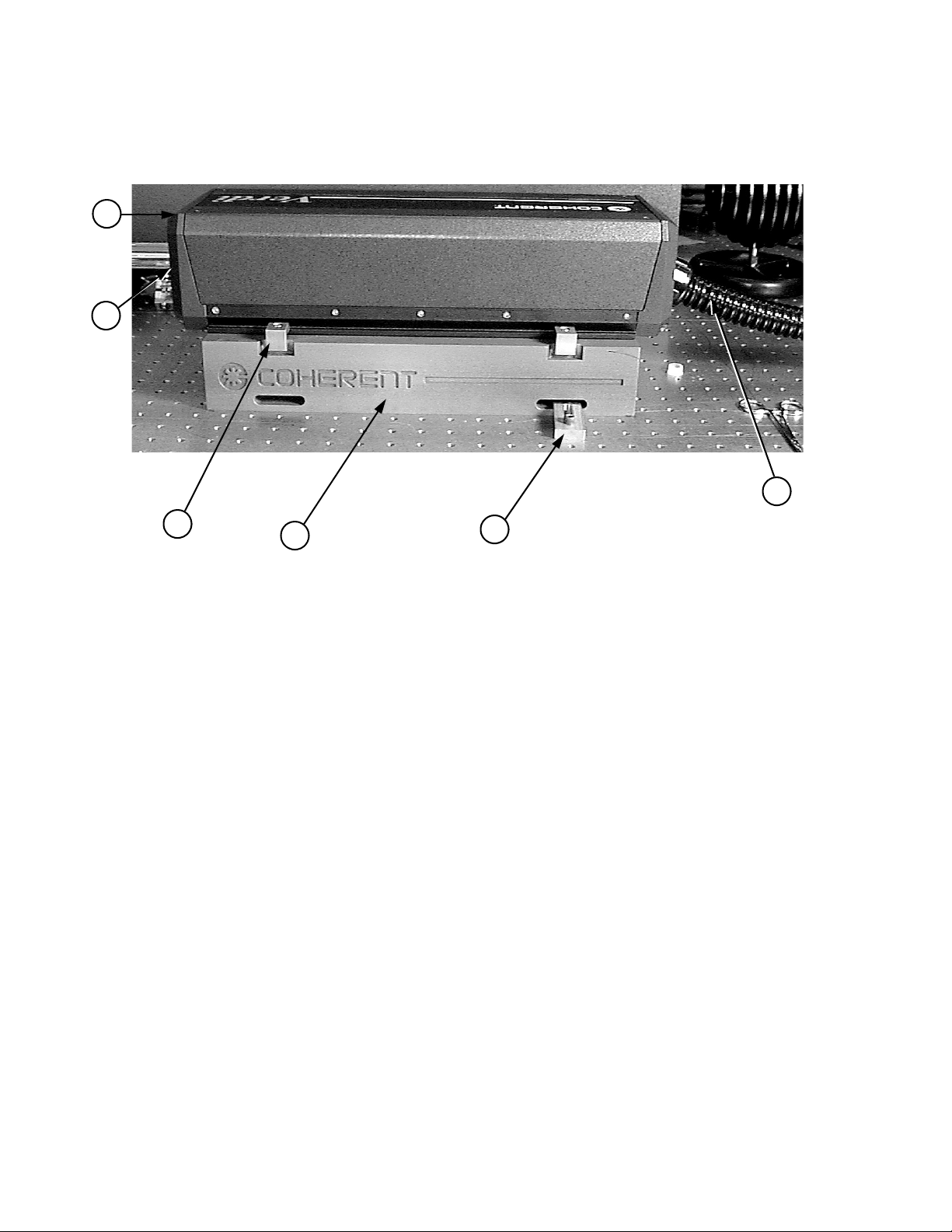
1
2
6
3
1. Emission indicator
2. Exit window
3. Clamps (4)
4
5
4. Riser/heat sink
5. Stable table clamps (4)
6. Umbilical
Figure 4-1. Laser Head Features
4 - 6
Page 39

Operation
Table 4-2. Laser Head Features
ITEM CONTROL FUNCTION
1 Emission indicator Lights when laser emission is possible.
2 Exit window 532 nm laser light is emitted from this window when the laser is on and the
shutter is open.
3 Clamps (4) Secures the laser head to the riser/heat sink.
4 Riser/Heat sink The passive riser/heat sink transfers heat from the laser head baseplate to
the mounting surface. The mounting surface must be capable of dissipating the transferred heat such that the baseplate temperature does not
exceed 55°C.
The optional water-cooled riser/heat sink needs no additional mounting
surface to maintain the base temperature below 55°C.
5 Optical table clamps (4) Secures the heat sink to the mounting surface.
The mounting surface must be capable of dissipating the transferred heat
such that the baseplate temperature does not exceed 55°C.
6 Umbilical Houses the fiber optic and electrical cables that provides an interface
between the laser head and power supply.
4 - 7
Page 40
Verdi V-2/V-5/V-6 Laser Operator’s Manual
1
2
4
3
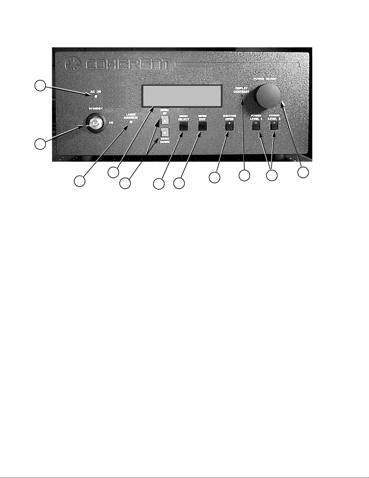
1. AC ON indicator
2. Key switch
3. LASER EMISSION indicator
4. Display
5. MENU UP/DOWN pushbuttons
6. MENU SELECT pushbutton
Figure 4-2. Power Supply Front Panel Controls and Indicators
5
6
7
8
9 10
11
7. MENU EXIT pushbutton
8. SHUTTER OPEN pushbutton indicator
9. DISPLAY CONTRAST adjust
10. POWER LEVEL 1/2 pushbutton indicators
11. POWER ADJUST knob
4 - 8
Page 41

Operation
Table 4-3. Power Supply Front Panel Controls and Indicators
ITEM CONTROL FUNCTION
1 AC ON indicator Lights when power is applied to the power supply via the power switch on
the rear panel.
2 Key switch The key switch can place the Verdi V-2/V-5/V-6 either in the STANDBY
or ON state. Functionality in these states are summarized in Table 4-1. The
key can be removed when in STANDBY position to prevent unauthorized
operation. The key cannot be removed when in ON position.
3 LASER EMISSION
indicator
4 Display Displays system status, operating parameters, and diagnostic data. Refer to
5 MENU UP/DOWN
pushbuttons
6 MENU SELECT push-
button
7 MENU EXIT push-
button
8 SHUTTER OPEN
pushbutton indicator
9 DISPLAY CONTRAST
adjust
10 POWER LEVEL 1/2
pushbutton indicators
Lights when laser emission is possible.
Figure 4-4 for a description of the displays.
Allows scrolling through the menus. Refer to Figure 4-4 for a description
of the displays and menus.
Allows selection of the indicated menu.
Exits current menu. Can also be used to clear inactive faults as described
in the troubleshooting charts in Section Six, Maintenance and Service.
Remotely opens and closes the external shutter on the laser head. When the
shutter is closed, the laser will go to idle at minimum power. If the
POWER ADJUST knob is not touched after the shutter is closed, the laser
will return that power setting once the shutter is opened. If the POWER
ADJUST knob is adjusted after the shutter is closed, then the laser will
ramp to the new setting after the shutter is opened.
Allows adjustment of the display by user for best viewing.
Allows selection of 2 preset laser output power levels. To preset a power
level, press the pushbutton to light the LED. Use the POWER ADJUST
knob to set the power, then press the pushbutton again so that the LED is
off. The new power value is then stored.
11 POWER ADJUST knob Allows continuous adjustment of output power level from threshold to
maximum power.
4 - 9
Page 42
Verdi V-2/V-5/V-6 Laser Operator’s Manual
5
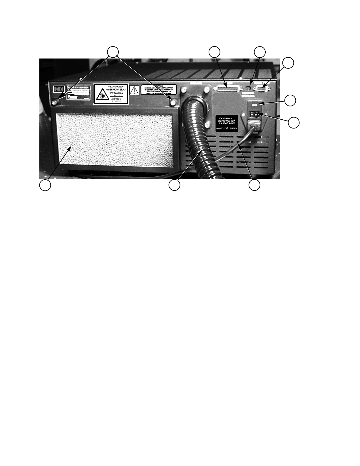
1. Fuses
2. Power ON/OFF switch
3. Power cord
4. Umbilical
5. Air filter
6
4
7
8
9
1
2
3
6. Air filter retaining nuts (2)
7. Reserved connector
8. EXTERNAL INTERLOCK connector
9. SERIAL PORT connector
Figure 4-3. Power Supply Rear Panel Controls and Indicators
4 - 10
Page 43
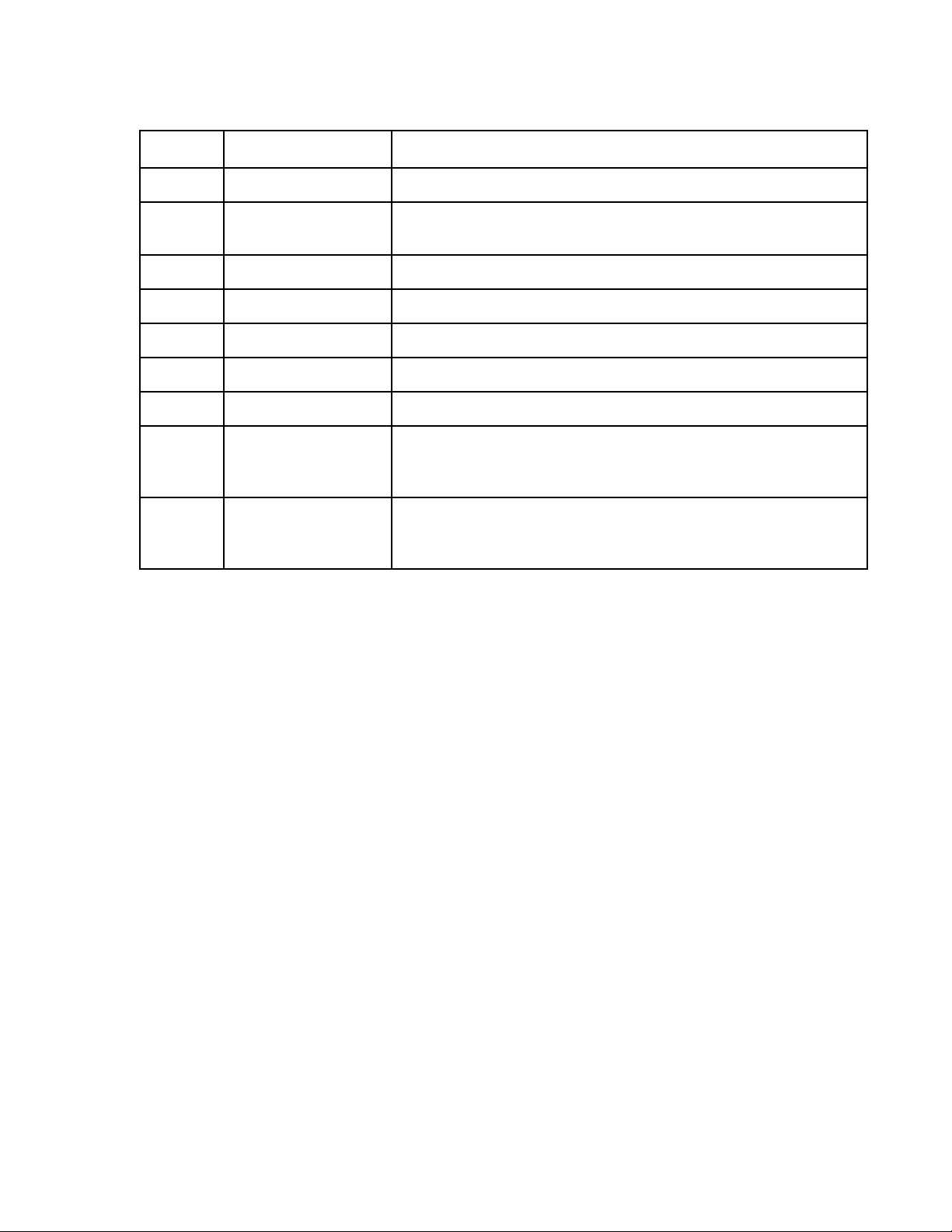
Table 4-4. Power Supply Rear Panel Controls and Indicators
ITEM CONTROL FUNCTION
1 Fuse 250 V, 10 A, time delay fuse provides electrical protection.
2 Power ON/OFF switch Applies/removes all power from the Verdi V-2/V-5/V-6. Refer to the
shut-down procedures to avoid unnecessary use of the internal battery.
3 Power cord Connects the power supply to AC facility power.
4 Umbilical Houses electrical and fiber optic cables.
5 Air filter Removes dirt and contamination from the power supply cooling air.
6 Air filter retaining nuts Secures air filter to power supply.
7 Reserved connector Reserved for future use.
Operation
8 EXTERNAL INTER-
LOCK connector
9 SERIAL PORT
connector
Allows connection of an external interlock. The laser will not operate
when this connector is open. Refer to the Section Three, Installation, for
additional information on the interlock.
Allows external computer control of the Verdi V-2/V-5/V-6. Refer to
Section Five for additional information on external computer control
including commands, queries, and system requirements.
4 - 11
Page 44

Verdi V-2/V-5/V-6 Laser Operator’s Manual
Menu Displays
Figure 4-4 shows the Verdi Main Display and the Base Menu
screens. The Base Menu screen can be reached from the Main
Display screen by pressing the SELECT pushbutton on the power
supply front panel. Once in the Base Menu screen, the user can
return to the Main Display screen by pressing the power supply
EXIT pushbutton.
Navigation through a list of submenus, such as those in the Base
Menu screen, is achieved by pressing the UP and DOWN arrow keys
on the power supply front cover. When the selection arrow (see
Figure 4-4) points to the desired submenu, that item can be activated
by pressing the SELECT pushbutton. Pressing the EXIT pushbutton
will deactivate the submenu, and re-display the Base Menu screen.
Examples and explanations for all Verdi submenus can be found in
Table 4-5.
to move arrow
Menu UP
Menu DOWN
Base Menu
Servo Status
Laser Status
FAULT Status
LBO Settings
LBO Optimization
Temperature Set Points
RS-232 Baudrate Setup
Etalon Capture
Speaker Volume
Diode Parameters
MAIN DISPLAY
Verdi V-6
Set Power:
6.00 W
System Status, Blank when System
is Locked at Set Power
STANDBY
Current:
20.43 A
SELECT
EXIT
System Status Messages
Figure 4-4. Menus
The current status of the laser system is displayed in the upper
right-hand corner of the Main Display screen of the software (see
Figure 4-4). Possible messages are:
• System Warming Up: Displayed while LBO crystal is.
heating.
• Standby. Displayed if power supply front panel keyswitch is
in the STANDBY position.
• Laser Seeking. Displayed while system is ramping the diode
current up to achieve set power. If the system is displaying this
message while the diode current is not changing, one or more
servo loops in the seek mode of operation. See the software
Servo Status Screen for additional information.
• Shutter Closed. Displayed if system head shutter has not been
opened.
4 - 12
Page 45

Operation
• Fault Active. Displayed if there is an active system fault. See
the Fault Status Screen for additional information.
• RS-232 Key Standby. Displayed if the laser system is placed
in STANDBY via the RS-232 command.
Fault Handling
In case of a fault, the CPU closes the shutter, sets the laser diode
current to zero, and displays the Fault Status Screen. For example:
!!!!!!!!!!!!!!!!!!!!!!!
FAULT CONDITION!
ERROR CODE #16
Diode 1 Over Current Fault
!!!!!!!!!!!!!!!!!!!!!!!
Push EXIT to continue
To clear a fault, the appropriate troubleshooting steps should be
taken. The power supply keyswitch should be turned to the
STANDBY position and the EXIT pushbutton pressed. See
Table 6-1 on page 6-1 for a complete listing of system faults and
troubleshooting procedures.
When the condition that caused the fault no longer exists, exit the
Fault Status screen to clear the fault. Once the keyswitch is turned to
the ON position, laser operation returns to its pre-fault state, except
the shutter will remain closed.
If the fault condition still exists, the system message “FAULT
ACTIVE” will be displayed in the Main Display screen.
4 - 13
Page 46

Verdi V-2/V-5/V-6 Laser Operator’s Manual
Low Power Warning
If the system maximum diode drive current is reached, and the
requested output power is not obtained, the power supply will beep
and a “LOW POWER!!” warning message will be displayed in the
lower right-hand corner of the Main Display screen.
Verdi V-6
Current:
Set Power 30.45 A
6.00 W
LOW POWER!!
(4.14 Watts)
Shutdown: 567 sec
If this message is observed, the output power setpoint should be
decreased until it is less than the value in the warning message and
the LBO optimization procedure should be run. If the warning
message reappears after LBO optimization, contact your local
Coherent service representative.
If the output power setpoint is not decreased, the system will shut
down with a “Diode Over Current” fault after 600 seconds has
elapsed.
Table 4-5. Submenus (Sheet 1 of 3)
Servo Status Screen
Servo: State W/deg C Drive
Laser: lock 5.00 21000
LBO: lock 146.00 4784
Vanadate: lock 30.00 -1776
Vanadate 2: lock 30.00 -1776
Etalon: lock 46.00 428
Diode 1: *seek 16.51 -1413
Laser Status Screen
S/W Version : 8.82, 9/2/99
Heatsink #1 T : 22.32 C
Baseplate T : 28.40 C
HEAD Hrs : 54.75 Sys: 7/23/99
DIODE1 Hrs : 64.05 I: 24.40 A
Displays the Verdi servo status: “OPEN,” “LOCK,” “SEEK,”
“*SEEK,” or “FAULT.” The value for the laser light loop servo is in
Watts and the other values (temperature servos) are °C.
*SEEK indicates the algorithm optimizing the diode temperature is
running. This algorithm optimizes the diode temperature such that
maximum laser rod absorption of the IR pump is achieved. Functionally, this lowers the diode pump power, and thus operating current,
necessary to achieve specified power. *SEEK is invoked automatically provided the system is running at 80% or greater output power.
Displays Verdi V-2/V-5/V-6 status and system information.
4 - 14
Page 47

Fault Status Screen
SYSTEM OK:
Operation
Table 4-5. Submenus (Sheet 2 of 3)
If faults are active, the fault codes and descriptions will be displayed.
Refer to Table 6-1 on page 6-1 for a complete list of faults and associated corrective actions. Refer to the paragraph titled, “Fault
Handling” for additional information on how to clear faults.
LBO Settings
T: 146.04 Set: 146.00
Drive: 4788
LBO Heating
Press SELECT to start COOLING
Press EXIT for NO CHANGE
LBO Optimization
T: 143.90 Pwr: 4.74 Drv: 6007
OK to OPTIMIZE LBO Temp
Press SELECT to OPTIMIZE Tlbo
Press EXIT to ABORT
Temperature Set Points
Set Pt: 144.00 Drive: 5950.0
Read T: 144.00 Status: lock
Set Pwr: 5.00W Avg I: 23.28A
->LBO Temperature
Vanadate Temperature
…Etalon Temperature
Diode #1 Temperature
Displays the state of the LBO servo (heating or cooling).
Access this menu to initiate heating or cooling of the LBO crystal. For
example, the cool-down cycle is initiated from this menu during the
“Complete Shutdown” procedure.
This menu is used to initiate LBO optimization. See paragraph titled,
“LBO Temperature Optimization” on page 6-40 for additional information and procedures regarding LBO optimization.
Displays the various system temperature set points, actual temperatures, and DAC drives required by the servo loops. Temperatures
cannot be changed from this menu.
RS-232 Baudrate Setup
RS-232 Protocol: 38400, 8, N, 1
Use KNOB to adjust rate values
Press SELECT to ACCEPT
Press EXIT to ABORT
Allows adjustment of the baud rate (factory set to 19,200) for RS-232
communications. See paragraph titled, “Setting The Baud Rate” on
page 5-3 for additional information on baud rate.
4 - 15
Page 48

Verdi V-2/V-5/V-6 Laser Operator’s Manual
Table 4-5. Submenus (Sheet 3 of 3)
Etalon Capture Screen
Press SELECT to Capture Mode
Press EXIT to return to menus
Speaker Volume Screen
-> Speaker Volume HIGH
Speaker Volume MEDIUM
Speaker Volume LOW
Speaker Volume OFF
Press SELECT to change
Press EXIT when done
Diode Parameters Screen
Diode 1 Voltage : 1.80V
Diode 1 Current : 17.50A
Diode 1 Photocell : 2.50V
The Etalon Capture Screen momentarily reduces the diode current
below lasing threshold to allow the single-frequency mode to
re-center. Re-centering is implemented each time the laser is turned
on.
The Speaker Volume Screen allows the audible beep (fault) volume to
be adjusted.
Displays diode voltage, current, and photocell values for the diodes.
Coherent recommends recording these values periodically to help
assess the health of the system.
The diode photocell voltage should be approximately 2.50 V, at
maximum output power level.
4 - 16
Page 49

External Computer Control
SECTION FIVE: EXTERNAL COMPUTER CONTROL
How to Interface Verdi Lasers
RS-232 Command Language
Instruction Syntax for RS-232 Communication
This section provides details on how to interface a Verdi
V-2 /V- 5/ V-6 la ser to a r em ot e c om puter via the RS-232 connector on
the rear of the power supply.
The RS-232 interface is based on a set of laser control instructions,
consisting of commands that affect laser operation, and queries that
request the laser to return status information to the host. The instruction set is sufficient to support user-written programs that emulate
the functions of the Verdi front panel.
Communication with the Verdi is with two types of instructions:
• Commands which set the values of laser operating parameters.
• Queries which request the laser to return the value of an oper-
ating parameter.
Any instruction to the laser consists of a command or query written
as a string of ASCII characters and terminated by a carriage return
and linefeed (<CR><LF>) or a semicolon (;).
For example:
LASER = 1<CR><LF>
Switches the Verdi from STANDBY to ON.
?LIGHT<CR><LF>
Requests the laser to return the measured laser output power.
The laser will always respond to an instruction by returning a
message terminated by a carriage return and linefeed. Table 5-1 lists
the possible responses from the laser.
5 - 1
Page 50
Verdi V-2/V-5/V-6 Laser Operator’s Manual
Table 5-1. Response from Laser after Receiving Instruction
INSTRUCTION
SENT TO LASER
ECHO OFF
PROMPT OFF
ECHO OFF
PROMPT ON
RESPONSE FROM LASER
ECHO ON
PROMPT OFF
ECHO ON
PROMPT ON
Command
+ <CR><LF>
Query + <CR><LF> Data + <CR><LF> Verdi> Data
Command
+ <CR><LF>
(Illegal operand)
Command <CR><LF>
(Illegal instruction)
Query<CR><LF>
(Illegal instruction)
1. Multiple items will be separated by the “&” character. For example, a list of system faults will be returned as
“3&5&6.”
<CR><LF> Verdi><CR> <LF> Command
+ <CR><LF>
Query + Data
RANGE ERROR:
+ Command
+ <CR><LF>
Command Error:
+ Command
+ <CR><LF>
Query Error:
+ Query
+ <CR><LF>
+ <CR><LF>
Verdi> RANGE
ERROR:
+ Command
+ <CR><LF>
Ver di > C om ma n d
Error: + Command
+ <CR><LF>
Ver di > Q ue r y
Error: + Query
+ <CR><LF>
+ <CR><LF>
Command
+ RANGE
ERROR:
+ Command
+ <CR><LF>
Command
+ Command Error:
+ Command
+ <CR><LF>
Query + Query
Error: + Query
+ <CR><LF>
Ver di > C om ma n d
+ <CR><LF>
Verdi> Query + Data
+ <CR><LF>
Ver di > C om ma n d
+ RANGE ERROR:
+ Command
+ <CR><LF>
Ver di > C om ma n d
+ Command Error:
+ Command
+ <CR><LF>
Ver di > Q ue r y
+ Query Error:
+Query
+ <CR><LF>
For proper handshaking, communication programs should wait
until the <CR><LF> has been returned from the laser before
sending the next instruction.
ECHO Mode The Verdi provides an “echo” mode in which each character trans-
mitted to the laser is echoed to the host. This feature can be turned
on or off using the ECHO command.
PROMPT Mode The Verdi provides a “prompt” mode for terminal operation in which
the laser returns; for example, “Verdi>” after each command. This
feature can be turned on or off using the “PROMPT” command.
5 - 2
Page 51

External Computer Control
? The single character “?” may be substituted for “PRINT” in all
queries. For example:
?LIGHT is equivalent to PRINT LIGHT
= or : The single characters = and : are equivalent delimiters between
text and data in all commands. For example:
LASER = 0 is equivalent to LASER: 0
RS-232 Interface Connection
RS-232 Port Configuration
CONFIGURATION DCE, NO HANDSHAKING
Data bits 8
Stop bits 1
Parity none
The Verdi Laser’s RS-232 port configuration is described in
Table 5-2, and typical cable requirements are shown in Figure 5-1.
The 9-pin RS-232 port is configured as data communications equipment (DCE) device using only pins 2 (serial data out), 3 (serial data
in) and 5 (signal ground). Handshake lines RTS, CTS, DTR and
DSR (pins 4, 6, 7 and 8) are not used and have no connections inside
the power supply.
Table 5-2. RS-232 Port Description
Baud rate User selectable:
Setting The Baud Rate
1200
2400
4800
9600
19200 (default factory setting)
38400
57600
The baud rate of the 9-pin RS-232 port can be adjusted through the
“RS-232 Baudrate Setup” menu on the front panel (Figure 4-4 on
page 4-12) or via the SERIAL BAUDRATE = NNN command
described in Table 5-1 and Table 5-2. After the baud rate is changed,
5 - 3
Page 52
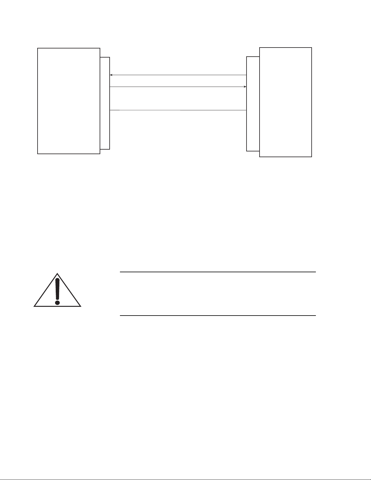
Verdi V-2/V-5/V-6 Laser Operator’s Manual
COMPUTER
DB9
1
2
3
4
5
6
7
Transmit Data (TXD)
Receive Data (RXD)
Signal Ground (GND)
DB9
1
2
3
4
5
6
7
VERDI
Figure 5-1. RS-232 Pin Configuration
the new setting will be used until it is changed even if the system
power is switched off.
To set the baud rate by the remote computer, send the SERIAL
BAUDRATE = NNN command to the laser at the currently set baud
rate. After sending this baud rate command, host computer communications port must be reinitialized to the new baud rate.
Instruction Set
The factory set baud rate is 19200.
When an RS-232 command is issued to change a setting, the
display may not update to reflect the changes taking place in the
system. The user should press MENU EXIT and MENU
SELECT to update the display.
Tables 5-3 and 5-4 describe the instructions (long and short forms)
for use in RS-232 with the Verdi.
5 - 4
Page 53

External Computer Control
Table 5-3. RS-232 Commands
COMMANDS ACTION PERFORMED
BAUDRATE = nnnnn
B=n
CHILLER Available only with Coherent-supplied chiller (part number1037271).
ECHO = n
E=n
EXIT SCREEN = 1
EXIT = 1
FLASH = 1
FL = 1
KNOB DOWN= 1
KNOBDN = 1
LASER = n
L=n
Sets the RS-232 Serial port baud rate to the specified value.
nnnnn = 1200, 2400, 4800, 9600, 19200, 38400, 57600.
= ON, = XX.X
If n = 0: turns echo OFF. Characters transmitted to the laser will not be
echoed to the host.
If n = 1: turns echo ON. Characters transmitted to the laser will be echoed
to the host.
A change in echo mode will take effect with the first command sent after
the echo command.
Duplicates EXIT button.
Flashes laser output below lasing threshold to allow single-frequency
mode (Etalon) to recenter.
Duplicates KNOB DOWN button.
If n = 0: puts laser in STANDBY (note: If the key is in the “ON” position,
then n = 0 will override)
If n = 1: resets faults and turns laser on (key must be in the “ON” position)
Clears fault screen on power supply and fault history (?FAULT
HISTORY) so lasing will resume if no active faults
LBO HEATER = n
LBOH = n
LBO OPTIMIZE = n
LBOOPT
LIGHT = nn.nnnn
P = nn.nnnn
LOCK FRONT PANEL = n
LFP = n
MENU DOWN = 1
MENUDN = 1
MENU SELECT= 1
SELECT = 1
MENU UP = 1
MENUUP= 1
If n = 0: turns LBO heater off (COOL DOWN)
If n = 1: turns LBO heater on (HEATING)
Initiates the LBO optimization.
1 = optimize
Sets light regulation to the specified output power.
Disables user input from the front panel.
Duplicates MENU DOWN button.
Duplicates MENU SELECT button.
Duplicates MENU UP button.
5 - 5
Page 54
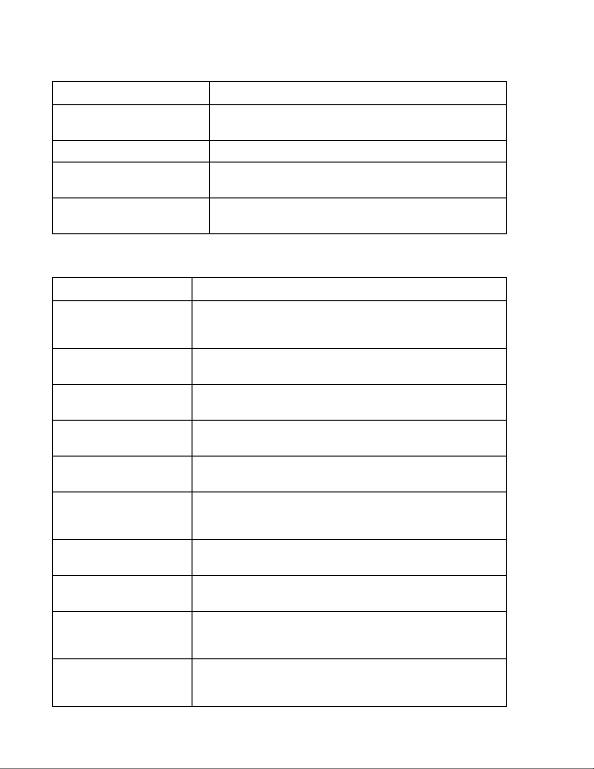
Verdi V-2/V-5/V-6 Laser Operator’s Manual
Table 5-3. RS-232 Commands (Continued)
COMMANDS ACTION PERFORMED
POWER = n
P = nn.nnnn
PRINT Works the same as a query; must be followed by a space
PROMPT = n
>=n
SHUTTER = n
S=n
Sets light regulation to the specified output power.
If n = 0: turns “Verdi>” prompt on
If n = 1: turns “Verdi>” prompt off
If n = 0: closes external shutter
If n = 1: opens external shutter
Table 5-4. RS-232 Queries (Sheet 1 of 5)
QUERIES RETURNED INFORMATION
PRINT AVG CURRENT AND
DELTA
?ACAD
PRINT BASEPLATE TEMP
?BT
PRINT BAUD RATE
?B
Returns the average diode current and the difference between them.
Returns laser head baseplate measured temperature, nn.nn, in °C.
Returns the baud rate of the Verdi V-2/V-5/V-6 serial port.
PRINT CURRENT
?C
PRINT DIODE1 CURRENT
?D1C
PRINT DIODE1 HEATSINK
TEMP
?D1HST
PRINT DIODE1 HOURS
?D1H
PRINT DIODE1 PHOTOCELL
?D1PC
PRINT DIODE1 RATED
CURRENT FACTOR
?D1RCF
PRINT DIODE1 RATED
CURRENT MAX
?D1RCM
Returns the measured average diode current, nn.n, in amps.
Returns laser diode #1 measured current, nn.n, in amps.
Returns laser diode #1 heat sink measured temperature, nn.nn, in °C.
Returns the number of operating hours on laser diode 1.
Returns light output power from diode 1 photocell.
Returns the factor that accounts for diode aging for diode 1.
Returns the maximum current at which diode 1 will be allowed to operate.
5 - 6
Page 55

External Computer Control
Table 5-4. RS-232 Queries (Sheet 2 of 5)
QUERIES RETURNED INFORMATION
PRINT DIODE1 SERVO
STATUS
?D1SS
PRINT DIODE1 SET TEMP
?D1ST
PRINT DIODE1 TEMP
DRIVE
?D1TD
PRINT DIODE1 TEMP
?D1T
PRINT DIODE1 5VREF
SENSE
?D15V
Returns the status of diode #1 temperature servo:
0 if the servo is OPEN
1 if the servo is LOCKED
2 if the servo is SEEKING
3 if the servo has a FAULT
4 if the servo is OPTIMIZING
5 if the servo is CPEAKING (Not available for V5 UNO, V6)
6 if the servo is CPEAKING2 (For V5 UNO, V6 only)
Returns laser diode #1 set temperature, nn.nn, in °C.
Returns laser diode #1 temperature servo drive setting.
Returns laser diode #1 measured temperature, nn.nn, in °C.
Returns a reference voltage used to measure the temperature of Diode 1.
PRINT DIODE OPTIMIZER
STATUS
?DIOS
PRINT ETALON DRIVE
?ED
PRINT ETALON SERVO
STATUS
?ESS
PRINT ETALON SET TEMP
?EST
PRINT ETALON TEMP
?ET
Returns diode optimizer status.
1 if the system is able to optimize
0 if not
Returns etalon temperature servo drive setting.
Returns the status of the etalon temperature servo:
0 if the servo is OPEN.
1 if the servo is LOCKED.
2 if the servo is SEEKING.
3 if the servo has a FAULT.
Returns etalon set temperature, nn.nn, in °C.
Returns measured Etalon temperature, nn.nn, in °C.
5 - 7
Page 56

Verdi V-2/V-5/V-6 Laser Operator’s Manual
Table 5-4. RS-232 Queries (Sheet 3 of 5)
QUERIES RETURNED INFORMATION
PRINT FAULTS
?F
PRINT FAULT HISTORY
?FH
PRINT HEAD_HOURS
?HH
PRINT KEYSWITCH
?K
1 = Laser Head Interlock Fault
2 = External Interlock Fault
3 = PS Cover Interlock Fault
4 = LBO Temperature Fault
5 = LBO Not Locked at Set Temp
6 = Vanadate Temp. Fault
7 = Etalon Temp. Fault
8 = Diode 1 Temp. Fault
10 = Baseplate Temp. Fault
11 = Heatsink 1 Temp. Fault
16 = Diode 1 Over Current Fault
Returns a list of number codes (see ?F) for all faults that have occurred since
the last LASER ON command, separated by an “&”, or return SYSTEM OK if
no latched faults. To clear the fault screen, when the fault is active, enter the
LASER ON command or the EXIT button on the power supply
Returns the number of operating hours on the system head.
Returns:
0 if the keyswitch is OFF
1 if the keyswitch is ON
18 = Over Current Fault
19 = Diode 1 Under Volt Fault21 =
Diode 1 Over Volt Fault25 = Diode 1
EEPROM Fault27 = Laser Head
EEPROM Fault
28 = Power Supply EEPROM Fault
29 = PS-Head Mismatch Fault
31 = Shutter State Mismatch
40 = Head-Diode Mismatch Fault
47 = Vanadate2 Temp. Fault
PRINT LASER
?L
PRINT LBO DRIVE
?LBOD
PRINT LBO HEATER
?LBOH
PRINT LBO OPTIMIZER
STATUS
?LBOOS
PRINT LBO SET TEMP
?LBOST
Returns:
0 if the laser is OFF (STANDBY)
1 if the laser is in ON
2 if the laser is OFF due to fault (check faults or fault history)
Returns LBO temperature servo drive setting.
Returns the status of the LBO heater:
0 if the LBO heater is OFF (COOL DOWN)
1 if the LBO heater is ON (HEATING)
Returns the LBO optimizer status:
1 if the system is able to run the LBO optimization
0 if not
Returns LBO set temperature, nnn.nn, in °C.
5 - 8
Page 57

External Computer Control
Table 5-4. RS-232 Queries (Sheet 4 of 5)
QUERIES RETURNED INFORMATION
PRINT LBO SERVO STATUS
?LBOSS
PRINT LBO TEMP
?LBOT
PRINT LIGHT
?P
PRINT LIGHT REG STATUS
?LRS
PRINT MODE
?M
Returns the status of the LBO temperature servo:
0 if the servo is OPEN
1 if the servo is LOCKED
2 if the servo is SEEKING
3 if the servo has a FAULT
4 if the servo is OPTIMIZING
5 if the servo is CPEAKING (Not available for V5 UNO, V6)
6 if the servo is CPEAKING2 (Only available for V5 UNO, V6)
Returns LBO measured temperature, nnn.nn, in °C.
Returns the calibrated output power, nn.nnn, in watts.
Returns the status of the light loop servo:
0 if the servo is OPEN (current regulation)
1 if the servo is LOCKED
2 if the servo is SEEKING
3 if the servo has a FAULT
Returns the mode of operation, whether current or light control.
1= light, 0= current
PRINT PS HOURS
?PSH
PRINT SET LIGHT
?SP
PRINT SHUTTER
?S
PRINT SOFTWARE
?SV
PRINT VANADATE SET
TEMP
?VST
PRINT VANADATE TEMP
?VT
Returns the number of power supply operating hours.
Returns the light regulation set power, nn.nnnn, in watts.
Returns the status of the external shutter:
0 if the shutter CLOSED
1 if the shutter OPEN
Returns the power supply software version number.
Returns vanadate #1 set temperature, nn.nn, in °C
Returns vanadate #1 measured temperature, nn.nn, in °C.
5 - 9
Page 58

Verdi V-2/V-5/V-6 Laser Operator’s Manual
Table 5-4. RS-232 Queries (Sheet 5 of 5)
QUERIES RETURNED INFORMATION
PRINT VANADATE DRIVE
?VD
PRINT VANADATE SERVO
STATUS
?VSS
Returns vanadate #1 temperature servo drive setting
Returns the status of the vanadate temperature servo:
0 if the servo is OPEN
1 if the servo is LOCKED
2 if the servo is SEEKING
3 if the servo has a FAULT
5 - 10
Page 59
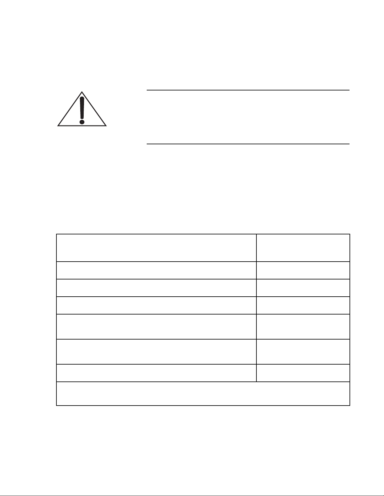
Maintenance and Service
SECTION SIX: MAINTENANCE AND SERVICE
Do not open the Verdi V-2/V-5/V-6 laser head. There are no
user-serviceable components or adjustments inside. There are
hazardous levels of laser energy inside the laser head. There is
no cover interlock to eliminate these dangers upon removal of
the laser head cover.
Troubleshooting
Table 6-1 lists possible problems/error messages with a reference to
the associated troubleshooting chart located in this section.
Table 6-1. Troubleshooting/Fault Messages (Sheet 1 of 3)
PROBLEM
Laser does not start (no laser output) Chart 1
Laser shuts down Chart 2
Laser output unstable Chart 3
AC ON indicator on power supply front panel does not light when power
switch on rear panel is on.
LASER EMISSION indicator on power supply front panel or on the laser
head does not light when keyswitch is in the “ON” position.
TROUBLESHOOTING
REFERENCE
Chart 4
See note [1]
Diode currents increase by 10% of baseline current. Chart 11
[1] Contact Coherent or an authorized representative. If the laser system or components are being returned directly
to Coherent, an RMA (Return Material Authorization) number is required.
6 - 1
Page 60

Verdi V-2/V-5/V-6 Laser Operator’s Manual
Table 6-1. Troubleshooting/Fault Messages (Sheet 2 of 3)
PROBLEM
TROUBLESHOOTING
REFERENCE
FAULT MESSAGES:
Fault Code 1: Laser Emission Lamp Fault Chart 5
Fault Code 2: External Interlock Fault Chart 6
Fault Code 3: PS Cover Interlock Fault Chart 7
Fault Code 4: LBO Temperature Fault Chart 8
Fault Code 5: LBO Not Locked at Set Temperature Chart 12
Fault Code 6: Vanadate Temperature Fault Chart 8
Fault Code 7: Etalon Temperature Fault Chart 8
Fault Code 8: Diode 1 Temperature Fault Chart 8
Fault Code 10: Baseplate Temperature Fault Chart 9
Fault Code 11: Diode Heat Sink 1 Temperature Fault Chart 10
Fault Code 16: Diode 1 Over Current Fault Chart 11
Fault Code 18: Over Current Fault Chart 11
Fault Code 19: Diode 1 Under Voltage Fault Chart 12
Fault Code 21: Diode 1 Over Voltage Fault Chart 12
Fault Code 25: Diode 1 EEPROM Fault Chart 12
Fault Code 27: Laser Head EEPROM Fault Chart 12
Fault Code 28: Power Supply EEPROM Fault Chart 12
Fault Code 29: Power Supply-Head Mismatch Fault Chart 12
Fault Code 30: Battery Requires Service Chart 13
6 - 2
Page 61

Maintenance and Service
Table 6-1. Troubleshooting/Fault Messages (Sheet 3 of 3)
PROBLEM
Fault Code 31: Shutter State Mismatch Chart 12
Fault Code 40: Head-Diode Mismatch Fault Chart 12
TROUBLESHOOTING
REFERENCE
6 - 3
Page 62
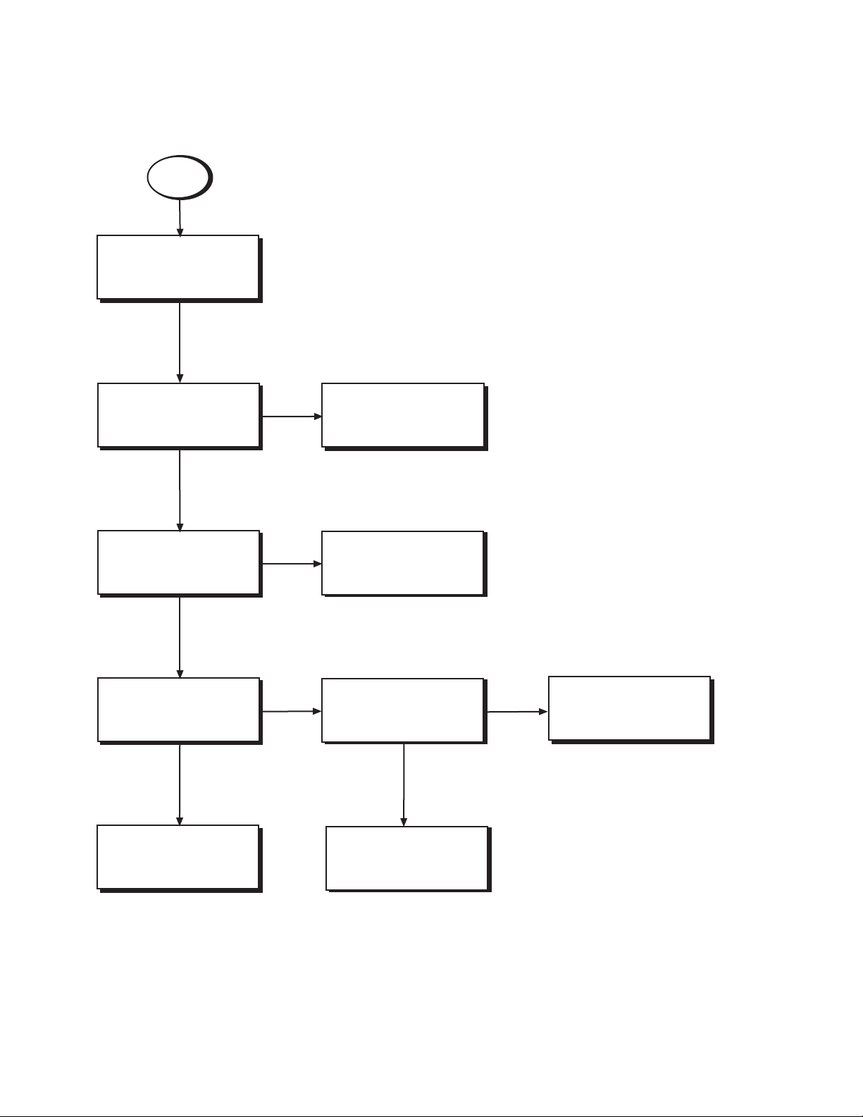
Verdi V-2/V-5/V-6 Laser Operator’s Manual
Chart 1. Laser Does Not Start (No Light Output)
Start
Refer to the assumptions
on the facing page
[1]
AC power indicator lit?
YES
Display visible?
YES
Any fault messages
displayed?
Clear fault? Fault active?
YES
NO
NO
NO
Refer to Chart 4.
Contact Coherent service
or an authorized service
representative.
Shutter Open?
YES
[2]
NO
Refer to Table 6-1.
Refer to Table 6-1.
Contact Coherent service
or an authorized service
representative.
6 - 4
[2]
Page 63

Maintenance and Service
Chart 1. Laser Does Not Start (No Light Output) [Continued]
The numbered paragraphs below are keyed to supplement this flowchart.
[1] ASSUMPTIONS:
• The laser system has been installed in accordance with the installation procedures in Section Three:
Installation.
• This procedure is not intended to re-start a laser after it has shut down due to a fault.
• A closed shutter is not blocking output light.
• The appropriate turn-on procedures are performed and the laser is not in a warm-up cycle.
[2] If the laser system must be returned directly to Coherent, an RMA (Return Material Authorization) number
is required. Contact Coherent or an authorized representative.
6 - 5
Page 64
Verdi V-2/V-5/V-6 Laser Operator’s Manual
Chart 2. Laser Shuts Down (No Light Output)
Start
Refer to the assumptions
on the facing page
[1]
AC indicator on?
YES
Any fault messages
displayed?
YES
Refer to Table 6-1.
NO
NO
Refer to Chart 4.
Contact Coherent service
or an authorized service
representative.
[2]
6 - 6
Page 65

Maintenance and Service
Chart 2. Laser Shuts Down (No Light Output) [Continued]
The numbered paragraphs below are keyed to supplement this flowchart.
[1] ASSUMPTIONS:
• The laser system had been operating immediately prior to shutdown.
• The interlocks are closed as described in Section Three: Installation. The laser will not operate with
an interlock circuit open.
If a user interlock is installed, the user interlock can be verified by temporarily replacing it with the
interlock supplied with the system.
[2] If the laser system must be returned directly to Coherent, an RMA (Return Material Authorization) number
is required. Contact Coherent or an authorized representative.
6 - 7
Page 66
Verdi V-2/V-5/V-6 Laser Operator’s Manual
Chart 3. Laser Output Unstable
Start
Refer to the assumptions
on the facing page
[1]
Any fault messages
displayed?
NO
Use the Etalon Capture
screen to flash laser.
Power unstable?
YES
Check output power with an
external power meter.
Power unstable?
YES
Contact Coherent service
or an authorized service
representative.
[2]
[3]
YES
NO
NO
Refer to Table 6-1.
End
Contact Coherent service
or an authorized service
representative.
[3]
6 - 8
Page 67

Maintenance and Service
Chart 3. Laser Output Unstable [Continued]
The numbered paragraphs below are keyed to supplement this flowchart.
[1] ASSUMPTIONS:
• The laser system has been installed in accordance with the installation procedures in Section Three:
Installation.
[2] Refer to Figure 4-4 on page 4-12 to access the Etalon Capture Screen. Press SELECT from within the
screen to flash the laser.
[3] If the laser system must be returned directly to Coherent, an RMA (Return Material Authorization) number
is required. Contact Coherent or an authorized representative.
6 - 9
Page 68
Verdi V-2/V-5/V-6 Laser Operator’s Manual
Chart 4. AC ON Indicator Does Not Light
Start
Refer to the assumptions
on the facing page
[1]
Other indicators on power
supply front panel lit?
YES
Contact Coherent service
or an authorized service
representative.
[4]
NO
Verify facility power.
Facility power OK?
NO
Correct facility power
as required.
YES
Check power supply fuse.
Fuse OK?
NO
Replace fuse.
YES
[2]
[3]
6 - 10
Page 69

Maintenance and Service
Chart 4. AC ON Indicator Does Not Light [Continued]
The numbered paragraphs below are keyed to supplement this flowchart.
[1] ASSUMPTIONS:
• The laser system has been installed in accordance with the installation procedures in Section Three:
Installation.
• The power cord is connected to an active facility power source and the power switch on the power
supply rear panel is on.
[2] After performing the “Turn-off (Complete Shut-down)” on page 4-5”, disconnect the laser system from
facility power and remove the fuse (Figure 4-3 on page 4-10, item 1) using the fuse replacement procedures located in this section. Verify continuity (closed circuit) between the two fuse terminals.
[3] Refer to the fuse replacement procedures located in this section. If the fault persists, contact Coherent or
an authorized representative.
[4] If the laser system must be returned directly to Coherent, an RMA (Return Material Authorization) number
is required. Contact Coherent or an authorized representative.
6 - 11
Page 70

Verdi V-2/V-5/V-6 Laser Operator’s Manual
Chart 5. Head Laser Emission Lamp Fault
[1] Press MENU EXIT to clear the fault display.
If the fault does not clear, a fault message will appear on the Main Display and on the Fault Status menu
(Figure 4-4 on page 4-12).
If the fault clears, open the shutter and resume operation.
[2] Ensure the umbilical is not strained or cut and that bend radius of the optical fiber is five inches or greater.
[3] Turn the power switch on the power supply rear panel to the OFF position for approximately 20 seconds.
Then turn the switch back to the “on” position.
[4] If the fault persists, contact Coherent or an authorized representative. If the laser system must be returned
directly to Coherent, an RMA (Return Material Authorization) number is required. Contact Coherent or an
authorized representative.
6 - 12
Page 71

Maintenance and Service
Chart 6. External Interlock Fault
The laser system will not operate with an open interlock circuit. Ensure the external
interlock is supplied with the system or a user furnished interlock is installed. See
paragraph titled, “External Interlock” on page 3-7 for more information on the external
interlock.
[1] Press MENU EXIT to clear the fault display.
If the fault does not clear, a fault message will appear on the Main Display and on the Fault Status menu
(Figure 4-4 on page 4-12).
If the fault clears, open the shutter and resume operation.
[2] Ensure the EXTERNAL interlock connector on the power supply rear panel is firmly seated.
[3] If a user interlock is installed, turn the keyswitch to STANDBY and replace the user interlock circuit with
the external interlock supplied with the system. If the fault clears, the user interlock circuit is defective.
If the fault does not clear, verify continuity of the interlock connector.
If the fault clears, open the shutter and resume operation.
[4] Turn the power switch on the power supply rear panel to OFF position for approximately 20 seconds. Then
turn the switch back to the “on.”
[5] If the fault persists, contact Coherent or an authorized representative. If the laser system must be returned
directly to Coherent, an RMA (Return Material Authorization) number is required. Contact Coherent or
an authorized representative.
6 - 13
Page 72

Verdi V-2/V-5/V-6 Laser Operator’s Manual
Chart 7. PS Interlock Fault
To ensure the top cover of the power supply is secure, turn the keyswitch to the STANDBY
position and verify the power supply top cover is closed with all fasteners fully tightened.
[1] Press MENU EXIT to clear the fault display.
If the fault does not clear, a fault message indication will appear on the Main Display and on the Fault
Status menu (Figure 4-4 on page 4-12).
If the fault clears, open the shutter and resume operation.
[2] Turn the power switch on the power supply rear panel to OFF position for approximately 20 seconds. Then
turn the switch back to the “on.”
[3] If the fault persists, contact Coherent or an authorized representative. If the laser system must be returned
directly to Coherent, an RMA (Return Material Authorization) number is required. Contact Coherent or
an authorized representative.
6 - 14
Page 73

Maintenance and Service
Chart 8. LBO Temperature Fault
Vanadate Temperature Fault
Etalon Temperature Fault
Diode 1 Temperature Fault
[1] Press MENU EXIT to clear the fault display.
If the fault does not clear, a fault message will appear on the Main Display and on the Fault Status menu
(Figure 4-4 on page 4-12).
If the fault clears, open the shutter and resume operation.
[2] Verify the set points in the “Temperature Set Points” submenu are the same as on the test sheet. If a diode
or LBO optimization has been performed, verify their temps are the same from the last optimization. If
different, contact Coherent or an authorized representative.
[3] Turn the power switch on the power supply rear panel to OFF position for approximately 20 seconds. Then
turn the switch back to the “on.”
[4] If the fault persists, contact Coherent or an authorized representative. If the laser system must be returned
directly to Coherent, an RMA (Return Material Authorization) number is required. Contact Coherent or an
authorized representative.
6 - 15
Page 74

Verdi V-2/V-5/V-6 Laser Operator’s Manual
Chart 9. Baseplate Temperature Fault
[1] Press MENU EXIT to clear the fault display.
If the fault does not clear, a fault message will appear on the Main Display and on the Fault Status menu
(Figure 4-4 on page 4-12).
If the fault clears, open the shutter and resume operation.
[2] Verify the laser head is installed on a riser/heat sink and the riser/heat sink is located on a surface that will
dissipate heat at a rate that will maintain the baseplate temperature below 55°C.
Ensure that the ambient temperature is not excessively high and the laser head is not located near a heat
generating source.
If a suitable ambient temperature cannot be maintained or if the laser head must be located in a less than
optimum location, an optional water cooled riser/heat sink is available from Coherent.
[3] Turn the power switch on the power supply rear panel to OFF position for approximately 20 seconds. Then
turn the switch back to the “on.”
[4] If the fault persists (and the ambient temperature and laser head location meet the above requirements),
contact Coherent or an authorized representative. If the laser system must be returned directly to Coherent,
an RMA (Return Material Authorization) number is required. Contact Coherent or an authorized representative.
6 - 16
Page 75

Maintenance and Service
Chart 10. Diode Heat Sink Temperature Fault
[1] Press MENU EXIT to clear the fault display.
Turn the keyswitch on the power supply front panel to STANDBY.
[2] Verify the following conditions are true:
• The cooling fans are not obstructed
• The rear, top, and left side of the power supply are not obstructed
• The air filter is not clogged (do not remove the air filter when the fans are rotating)
• The power supply is not located near a heat source
• The ambient temperature is not excessively high
[3] Turn the power switch on the power supply rear panel to OFF position for approximately 20 seconds. Then
turn the switch back to the “on.”
[4] If the fault persists (and the ambient temperature and power supply location meet the above requirements),
contact Coherent or an authorized representative. If the laser system must be returned directly to Coherent,
an RMA (Return Material Authorization) number is required. Contact Coherent or an authorized representative.
6 - 17
Page 76
Verdi V-2/V-5/V-6 Laser Operator’s Manual
Chart 11. Diode Over Current Fault
Over Current Fault
10% Current Increase (No Fault)
Start
Refer to the assumptions
on the facing page
[1]
Set the output power to
highest sustainable power
Fault active?
NO
Optimize the LBO temperature.
Spec power is achieved with no
fault displayed?
NO
Contact Coherent service
or an authorized service
representative.
[4]
[2]
[4]
YES
YES
[3]
YES
Contact Coherent service
or an authorized service
representative.
End.
[4]
6 - 18
Page 77

Maintenance and Service
Chart 11. Diode Over Current Fault [Continued]
Over Current Fault
10% Current Increase (No Fault)
[1] ASSUMPTIONS:
• The laser system has been installed in accordance with the installation procedures in Section Three:
Installation.
[2] If the fault is displayed, press EXIT to clear the fault.
[3] Use the LBO Optimization menu shown in Figure 4-4 on page 4-12 to perform the optimization routine.
[4] If the laser system must be returned directly to Coherent, an RMA (Return Material Authorization) number
is required. Contact Coherent or an authorized representative.
6 - 19
Page 78

Verdi V-2/V-5/V-6 Laser Operator’s Manual
Chart 12. Diode Under Voltage Fault
Diode Over Voltage Fault
Diode EEPROM Fault
LBO Not Locked at Set Temperature
Laser Head EEPROM Fault
Power Supply EEPROM Fault
Power Supply-Head Mismatch Fault
Shutter State Mismatch
Head-Diode Mismatch Fault
[1] To clear a fault, the power supply keyswitch should be turned to the STANDBY position, and the EXIT
push button pressed. If the fault condition no longer exists, exiting the Fault Status screen will clear the
fault. Once the keyswitch is turned to the ON position, laser operation returns to the state it was in before
the fault occurred except the shutter will be closed. If the fault condition still exists, the system message
“FAULT ACTIVE” will be displayed in the Main Display screen.
If the fault does not clear, a fault message will continue to appear on the Fault Status menu (Figure 4-4 on
page 4-12).
If the fault clears, open the shutter and resume operation.
Note: it may be necessary to wait for the LBO crystal to lock at the set temperature before resuming operation.
[2] Turn the power switch on the power supply rear panel to OFF position for approximately 20 seconds. Then
turn the switch back to the “on.”
[3] If the fault persists, contact Coherent or an authorized representative. If the laser system must be returned
directly to Coherent, an RMA (Return Material Authorization) number is required. Contact Coherent or an
authorized representative.
6 - 20
Page 79

Maintenance and Service
Chart 13. Battery Requires Service
[1] To clear a fault, press the MENU EXIT pushbutton and perform the complete shutdown. Wait at least five
seconds before turning the system on. Upon turn-on, verify the status of the system.
If the fault clears, open the shutter and resume operation.
Note: it may be necessary to wait for the LBO crystal to lock at the set temperature before resuming operation.
[2] If the fault persists, perform the procedure in paragraph titled, “Battery Replacement” on page 6-42. If the
fault still persists after replacing the battery, the laser system must be returned to Coherent. A Return Material Authorization (RMA) number is required. Contact Coherent or an authorized representative for more
information or to receive an RMA number.
6 - 21
Page 80
Verdi V-2/V-5/V-6 Laser Operator’s Manual
FAP-I Replacement
Preliminary Steps and Data
Refer to Table 6-1 for the troubleshooting charts prior to replacing
the FAP-I. Contact Coherent technical support or a local service
representative to assist in determining the need for FAP-I replacement.
1. With the laser system in STANDBY, record the following
system parameters from the “Temperature Set Points”
submenu:
a. LBO temperature set point
b. Vanadate temperature set points
c. Etalon temperature set point
d. FAP-I temperature set point
2. Perform the “Turn-off (Complete Shut-down)” on page 4-5.
The associated cool-down cycle takes approximately
30 minutes. The front panel display indicates when the
cool-down cycle is complete.
Do not turn the power switch on the rear panel to the OFF position or disconnect the AC power input until the cool-down cycle
is complete.
3. When the LBO cool-down cycle is complete, turn the power
switch on the power supply rear panel to the OFF position.
Do not disconnect the power cord from facility power. The
power supply chassis must be grounded either by the power
cord or a separate ground to avoid electro-static discharge
(ESD).
4. Remove the top cover of the power supply.
The FAP-I can be damaged by electro-static discharge (ESD). To
avoid ESD, a personal grounding strap must be used at all times.
6 - 22
Page 81
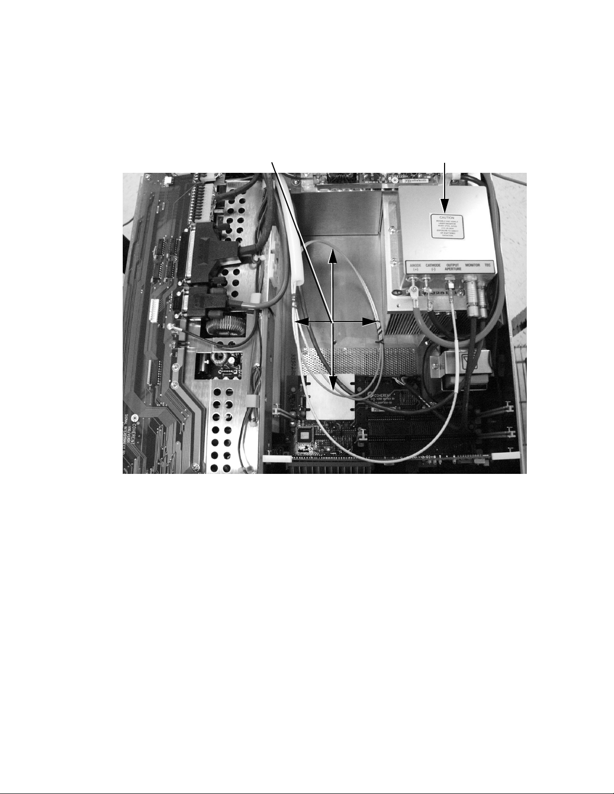
Maintenance and Service
FAP-I Handling Precautions
1. The FAP-I can be damaged by improper ESD handling. To
avoid ESD, a personal grounding strap must be used at all
times. Follow the instructions that accompany the personal
grounding strap.
6 inch Fiber Looping
FAP-I # 1
Figure 6-1. Location of FAP-I Assemblies and Fiber Looping
2. A shorting clip (Figure 6-2) must be installed between the
anode and cathode terminals to avoid inadvertent ESD before
the leads are disconnected from the terminals.
3. When disconnecting the fiber optic cable from the FAP-I
assembly, a cap (Figure 6-2) must be installed over both the
FAP-I optical emission port and the end of the fiber optic cable
to protect them from accidental damage or contamination.
6 - 23
Page 82
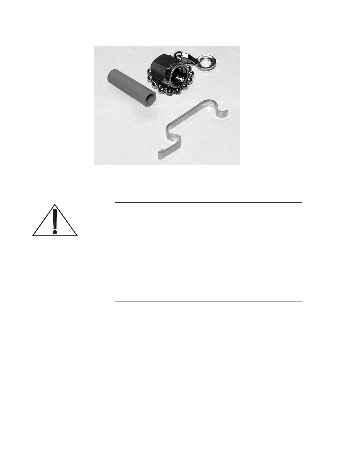
Verdi V-2/V-5/V-6 Laser Operator’s Manual
Figure 6-2. Fiber Optic Covers and FAP-I Anode/Cathode Shorting Clip
Fiber Cable Handling Precautions
The end of the fiber optic cable is an optical surface. Do not
allow the end of the fiber optic cable to make contact with any
surface, including the fingers.
A contaminated optical surface can cause system damage. To
minimize exposure to contaminants, the blue protective plastic
cap must be installed whenever the fiber is disconnected.
When removing or installing the fiber optic cable, do not allow
the fiber optic cable to rotate while loosening the ferrule
connector.
1. When removing or installing a fiber optic cable, do not allow
the fiber optic cable to rotate while loosening the ferrule
connector (Figure 6-4).
2. The end of the fiber optic cable is an optical surface. Do not
allow the end of the fiber optic cable to contact any surface,
including the fingers. To minimize exposure to the environment, the protective plastic cap must be left in place until a
6 - 24
Page 83
Maintenance and Service
connection is made and immediately installed over the fiber
end when a connection is disassembled.
3. Do not allow the end of the fiber optic cable to contact the
diode (FAP-I) assembly or any other surface including the
fingers. Failure to do so can damage the optical surface.
Inspect the fiber optical surface to verify the cleaning procedure
is necessary.
4. Do not install a contaminated or damaged fiber optic cable to
the FAP-I. Doing so will cause a failure of the laser system.
Contamination or damage can be difficult to detect. A magnifying glass may help during the inspection
to
Do not use acetone as a cleaning solvent on fiber optical surfaces.
It will dissolve the matrix that supports the fiber and will
destroy the optical transport fiber permanently.
FAP-I Removal
5. The end of the fiber optic cable should be cleaned using the
“Drop and Drag” procedure. Refer to the paragraph titled,
“LBO Temperature Optimization” on page 6-40. Do not use
any other procedure or method. If scratches or other damage is
present, the FAP-I replacement should be terminated and the
plastic cap reinstalled. Contact Coherent or an authorized local
representative.
6. Excessively tight fiber umbilical bends (less than a 3-inch
radius) can cause permanent damage to the transport fiber.
1. Install shorting clip (Figure 6-2) between anode and cathode of
FAP-I assembly to be removed. Disconnect the anode and
cathode connectors, see Figure 6-3.
2. Disconnect the Case/Anode ground jumper from the FAP-I
assembly.
Wear finger cots (supplied with the replacement FAP-I) while
handling the fiber optic cable.
6 - 25
Page 84
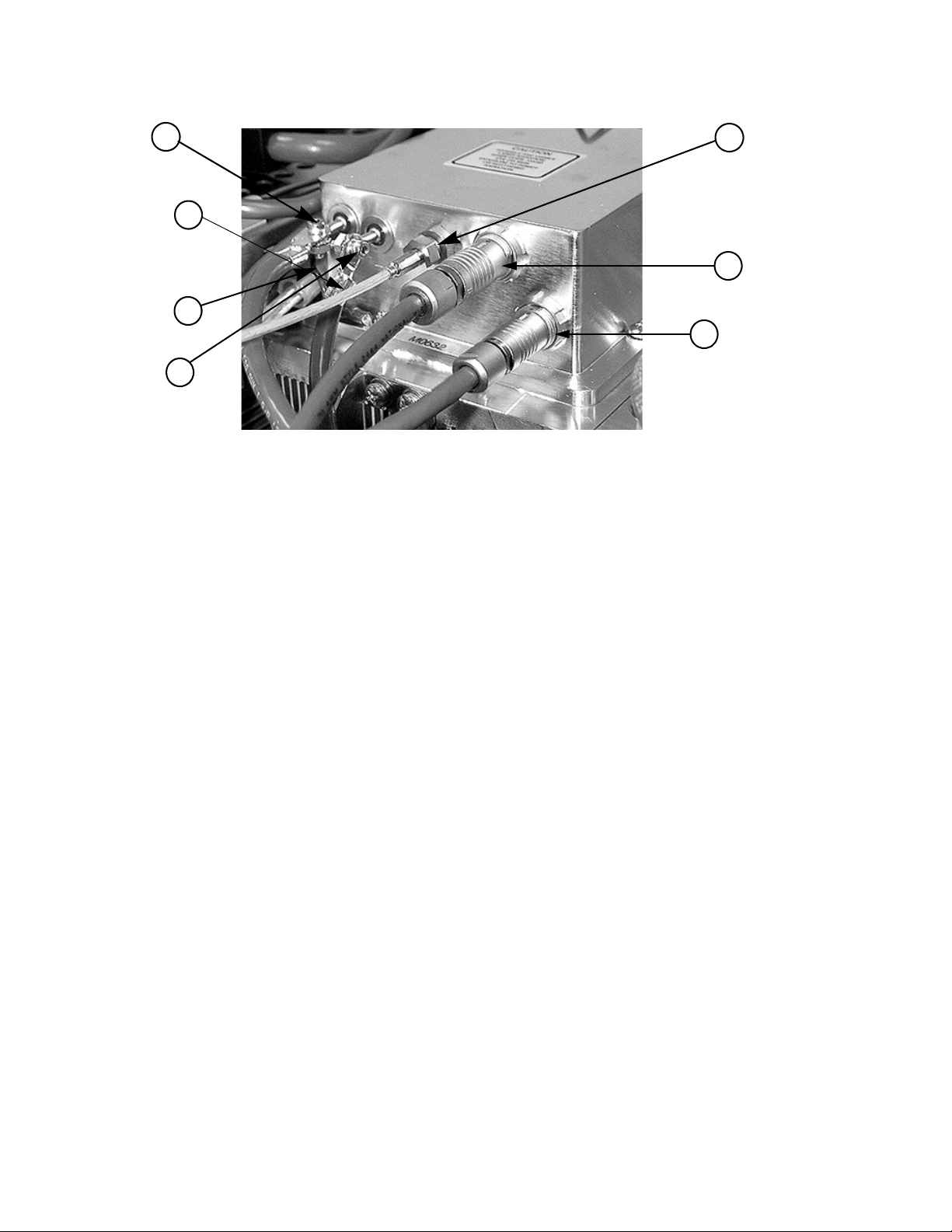
Verdi V-2/V-5/V-6 Laser Operator’s Manual
1
7
3
2
1. Anode Connector Terminal
2. Cathode Connector Terminal
3. Case/Anode Ground Jumper
4. Fiber Optic Connector and Optical
Emission Port
4
5
6
5. Personality Module, Thermistors,
Diode Hours Connector
6. TEC Coolers Inputs/Outputs Connector
7. Fiber Optic Cable
Figure 6-3. FAP-I Assembly Interface
3. Disconnect the fiber optic cable as follows:
a. While firmly holding the fiber optic cable, loosen the
ferrule connector securing the fiber optic cable to the
FAP-I. It may be necessary to use a small wrench to
loosen the connector.
b. Note the ferrule cutout (see Figure 6-4). Carefully
extract the fiber optic cable from the FAP-I and remove
the ferrule.
c. Immediately install the two plastic protective caps, one
over the end of the fiber cable and the second over the
FAP-I optical output port (Figure 6-2).
4. Disconnect the Personality module and TEC connectors from
the FAP-I assemblies by pulling back on the outer sleeve and
then unplugging the connector.
5. Remove the eight screws securing the FAP-I to the heat sink
(two on each side).
6 - 26
Page 85
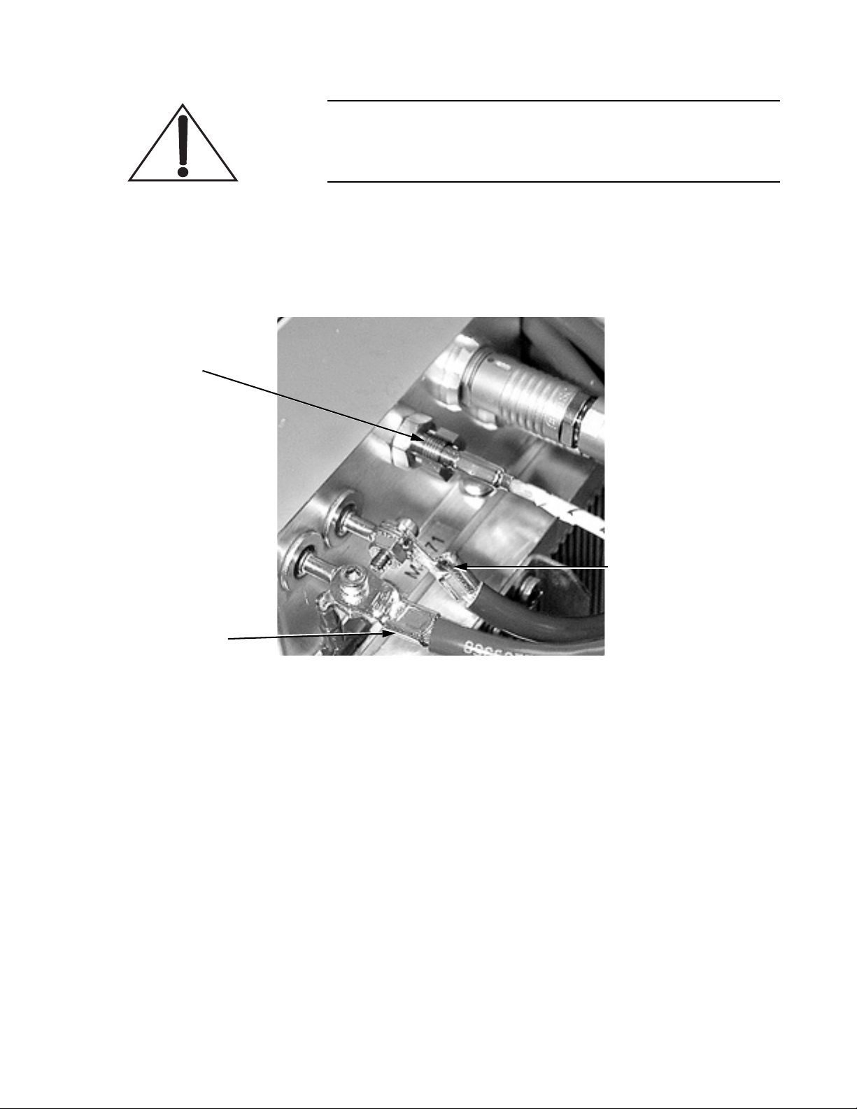
Ferrule Cutout
Maintenance and Service
Due to the thermal grease on the bottom of the FAP-I assembly,
it may be necessary to work the old assembly loose by rotating
(wiggling) it back and forth around its center.
6. Remove the FAP-I from the power supply and clean the
thermal grease from the FAP-I and the mounting surface
(alcohol works well for this).
Proper Installation,
Anode Lead (red)
Horizontally
Oriented
FAP-I Installation
Proper Installation,
Cathode Lead (black)
Vertically Oriented
Figure 6-4. FAP-I Fiber Optic Connector
The following items are included in the FAP-I installation kit:
• FAP-I ass embl y
• Die-cut plastic masking sticker
• Tube of thermal compound
• Plastic spatula for spreading thermal compound
• Fiber optic cap
• Finger cot for fiber handling
6 - 27
Page 86
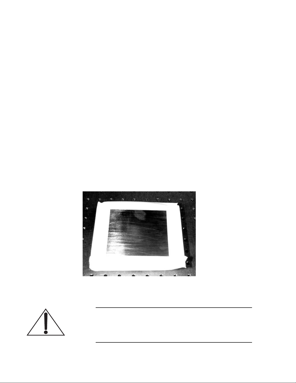
Verdi V-2/V-5/V-6 Laser Operator’s Manual
1. Remove the new FAP-I from the shipping container. Leave the
shorting clip and protective plastic cap in place to avoid
possible ESD and contamination damage.
2. Apply the die-cut template to the bottom of the diode to avoid
contaminating the screw holes with thermal compound in the
next step. Alternatively, place masking tape over the edges of
the FAP-I baseplate as illustrated in Figure 6-5.
3. Using the plastic applicator, apply an even coating of thermal
grease to the bottom of the FAP-I. The thickness of the grease
film should be less than the thickness of the masking tape or
template.
4. Remove the template or masking tape.
5. Position the FAP-I assembly on the heat sink.
6. Re-attach the Case/Anode ground jumper to the FAP-I baseplate.
7. Secure the FAP-I to the heat sink using the remaining seven
mounting screws.
8. Remove any excess thermal grease from around the assembly.
Figure 6-5. Preparation of the Replacement FAP-I Assembly
After connection, the red anode lead should be horizontally
oriented and the black cathode lead should be vertically
oriented. This is illustrated in Figure 6-4 and minimizes the
potential of generating/picking up EM noise.
6 - 28
Page 87

Maintenance and Service
9. Re-connect the anode and cathode leads. Be sure to reconnect
the case/anode ground jumper when connecting the anode
lead.
10. Remove the anode/cathode shorting clip.
11. Re-connect the Personality module and TEC connectors.
12. Inspect, and, if necessary, clean the fiber optic surface. (See the
procedure titled “LBO Temperature Optimization” below).
13. Re-connect the fiber optic cable to the FAP-I, securing the nut
finger-tight (no more than 4 in-lbs. if using a torque wrench).
14. If disconnected, re-connect the AC power cord to facility
power. If a ground wire was used, remove it.
15. Replace the power supply cover and perform the procedure in
paragraph titled, “Turn-on (Cold-Start)” on page 4-2.
16. Verify system parameters.
Fiber Optic Cleaning
Before performing the cleaning procedure, inspect the fiber optic
surface with a fiberscope or magnifier to determine the extent to
which the fiber might be damaged or contaminated. Only perform
the cleaning procedure if the fiber optic surface shows imperfections, otherwise the procedure may introduce dust, dirt, or potentially induce damage to the fiber optic. Reference the figures titled
“Good Fiber” on page 6-38, “Bad or Questionable Fibers” on
page 6-38, and “Guidelines for Fiber Optic Inspection” on
page 6-39 to determine if the fiber requires cleaning and/or replacement.
The Drop and Drag method is the least abrasive cleaning method and
should always be used first to remove imperfections on the fiber
optic surface. If the Drop and Drag method will not remove particulates, then the fiber optic surface should be cleaned with a cleanroom
swab. The cleanroom swab is most effective; however, a lens tissue
with a hemostat may be used as an alternative to the cleanroom
swab.
6 - 29
Page 88
Verdi V-2/V-5/V-6 Laser Operator’s Manual
Equipment Needed
The following materials are required to perform this procedure:
• Lens cleaning tissue
• Cleanroom-quality swabs
(Coherent recommends using Micro Alpha Swab ESD, Part
#1488-758E from Cintas at (800) 786-6027)
Lens tissue and a hemostat may be used as an alternative to the
swabs.
• Fresh spectroscopic-grade Methanol
• Fiber microscope (fiberscope), 200X total magnification
• Non-powdered, non-coated Latex (or equivalent) gloves or
fingercots
Important: Do not use Acetone! Acetone will dissolve adhesives
used in the manufacture of the fiber optic and will destroy the
fiber optic cable.
Fiberscope
Procedure
Drop and Drag Procedure
A recommended cost-effective fiberscope is the OFS 300-200C
model with 20X eyepiece and SMA adapter manufactured by
Noyes™. See Figure 6-6.
Always wear latex gloves or fingercots (or the equivalent) while
performing any of the following procedures. Fingerprints, dust,
condensation, and oils from the hand can damage the fiber optic
surface.
1. Using a medicine dropper and a new, clean lens tissue, put one
drop of Methanol near the center of the lens tissue. See
Figure 6-7.
2. Holding the fiber vertically so the fiber surface points to the
ceiling, carefully place the tissue so the optical surface rubs
against the underside of the tissue. See Figure 6-8.
3. In a single movement, gently drag the fiber surface against the
underside of the wet tissue in a circle, spiraling out, taking care
not to go over the same part of the tissue twice. See Figure 6-9.
Drag the fiber out from the saturated part of the tissue to the
dry parts of the tissue, which dries the fiber optic surface and
prevents Methanol residue.
6 - 30
Page 89
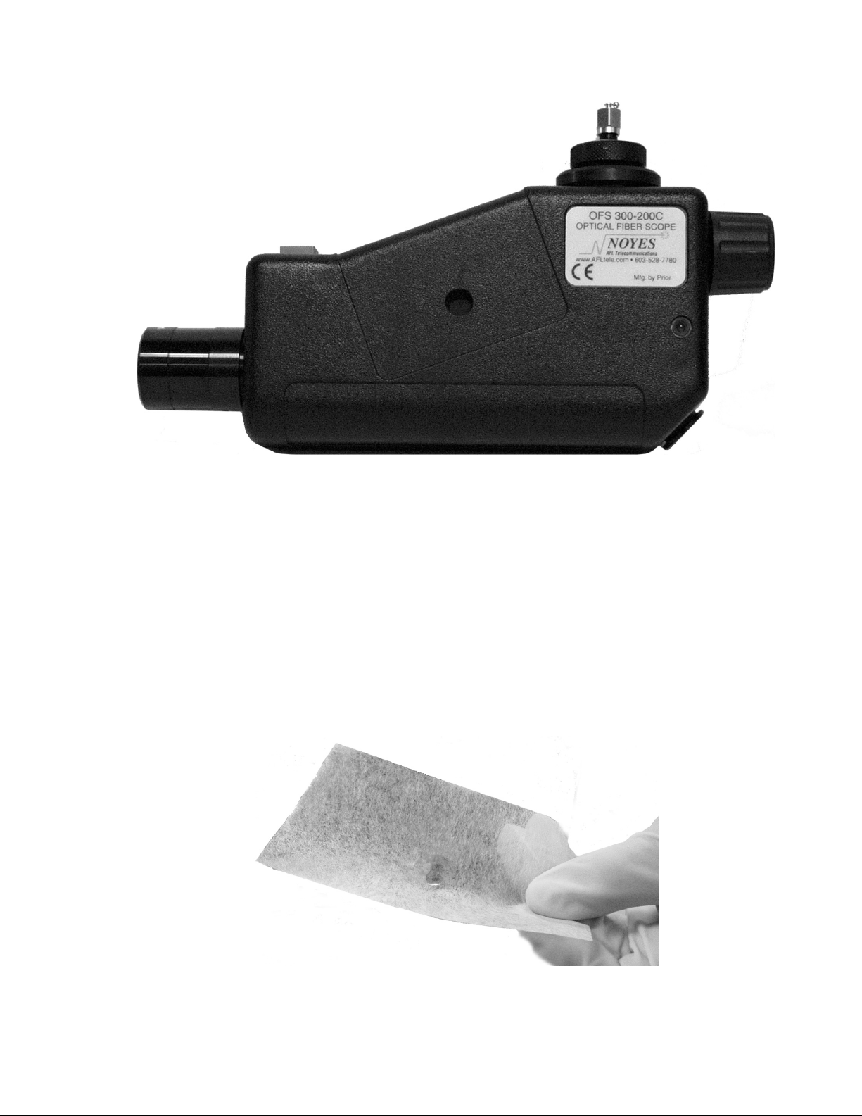
Maintenance and Service
Figure 6-6. Fiberscope with 20X Eyepiece and SMA Adapter
4. Re-check the fiber with the fiberscope.
If the fiber surface is now ideal or complies with the acceptable
guidelines as illustrated in Figure 6-19 on page 6-39, immediately install the fiber optic into the FAP-I/FAP-B.
If the imperfections have not been removed, or if any Methanol residue has been induced (See Figure 6-10), continue
with the cleanroom swab procedure below.
Figure 6-7. Methanol Drop on Lens Tissue
6 - 31
Page 90
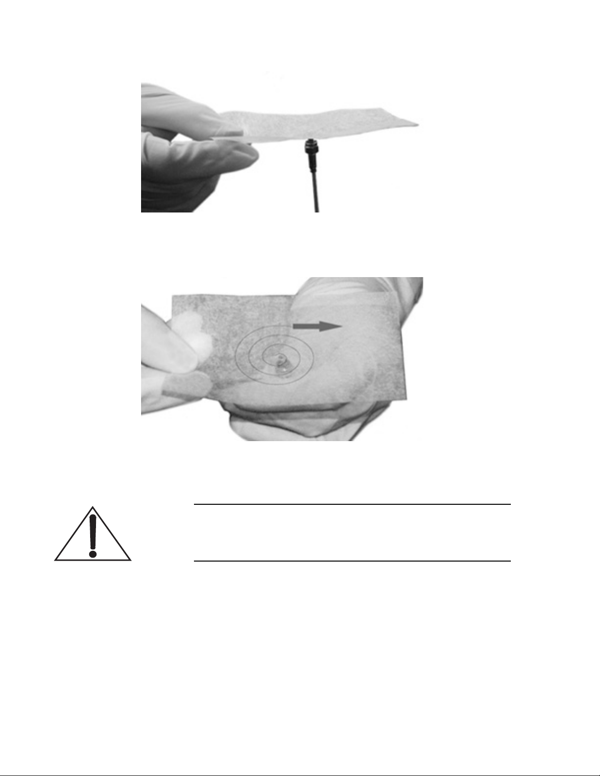
Verdi V-2/V-5/V-6 Laser Operator’s Manual
Figure 6-8. Placement of the Fiber Optic Against the Lens Tissue
Figure 6-9. Movement of Fiber Optic Against Lens Tissue
Methanol residue can cause burn spots or potentially catastrophic damage to the fiber optic and the FAP-I/FAP-B. See
Figure 6-10 for an illustration of Methanol residue.
6 - 32
Page 91
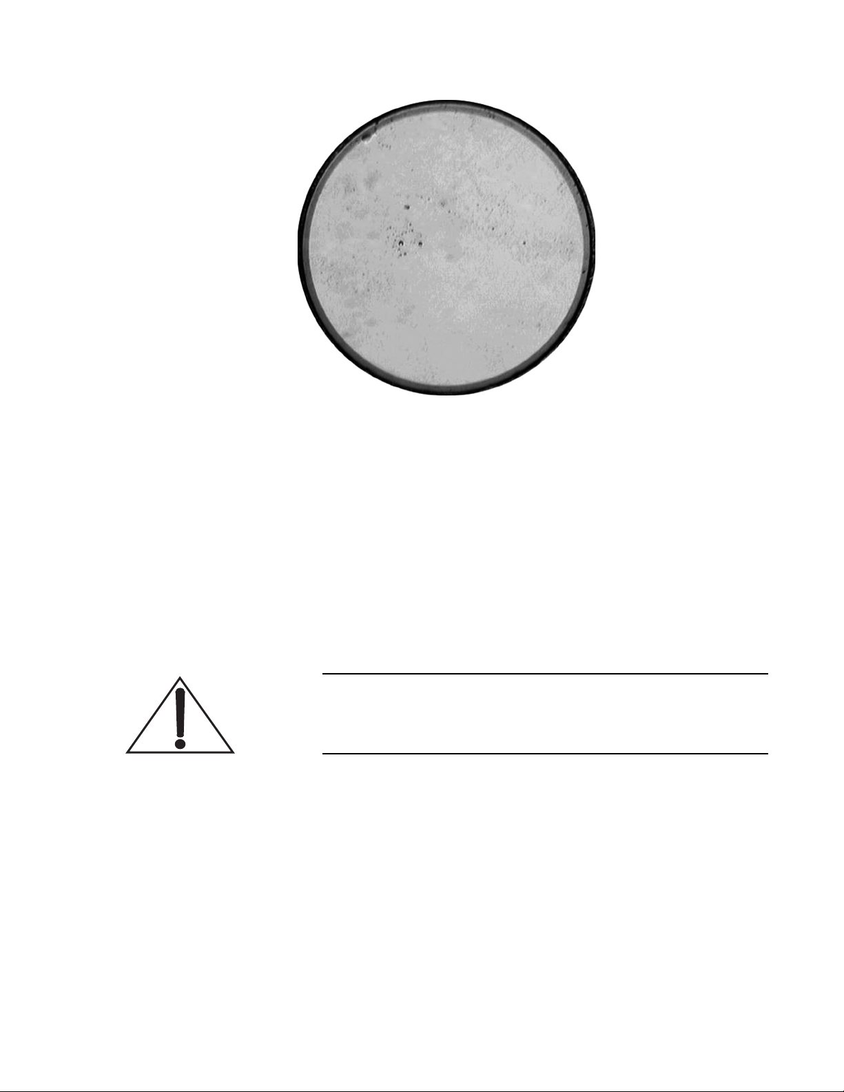
Figure 6-10. Methanol Residue
Maintenance and Service
Cleanroom Swab Procedure
Using lens tissue and a hemostat may be substituted for the cleanroom swab procedure. Reference the procedure titled “Alternative
Cleaning Procedure” on page 6-35 for the alternate method.
1. Using a medicine dropper, put one to two drops of Methanol
on the swab (Figure 6-11).
2. Vigorously shake off excess Methanol from the swab to
prevent Methanol residue.
Only the synthetic cloth should make contact with the fiber optic
surface. Do not allow the plastic applicator to touch the fiber
surface.
3. Holding the fiber vertically so the fiber surface points to the
ceiling, carefully place the base of the swab against the fiber
optic surface, taking care not to touch the plastic applicator to
the fiber optic surface. See Figure 6-12.
4. Drag the swab across the fiber optic surface in a single stroke.
Do not drag the swab back and forth.
5. Repeat Step 4 using the other side of the swab.
6 - 33
Page 92
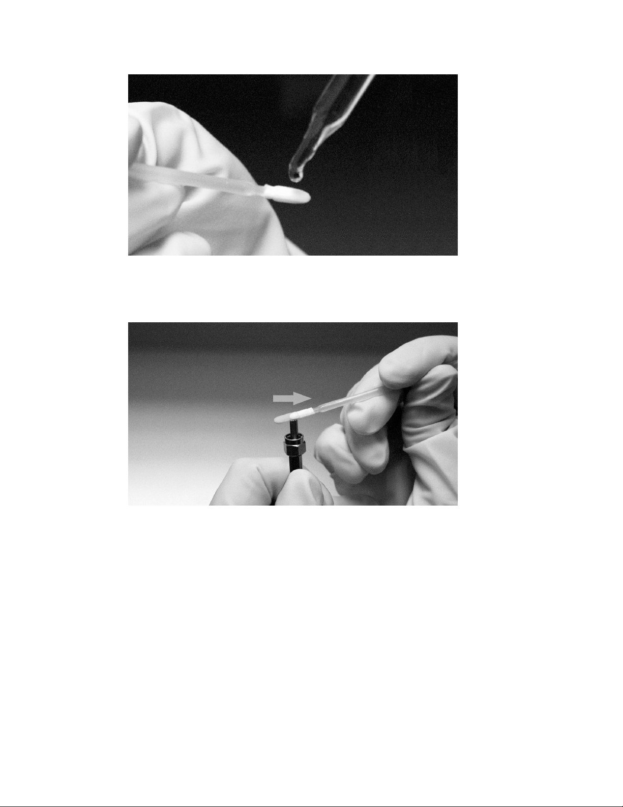
Verdi V-2/V-5/V-6 Laser Operator’s Manual
Figure 6-11. Methanol Drop
Figure 6-12. Placement and Movement of the Swab Against the Fiber Optic Surface
6. Re-check the fiber using the fiberscope.
If the fiber surface is now ideal or complies with the acceptable
guidelines as illustrated in Figure 6-19 on page 6-39, immediately install the fiber optic into the FAP-I/FAP-B.
If imperfections remain, repeat the procedure using a new
swab.
7. If imperfections still remain, compare the image in the fiberscope with Figure 6-19 on page 6-39 and determine whether
the fiber optic must be replaced. Contact Coherent Service if
further guidance is needed.
6 - 34
Page 93
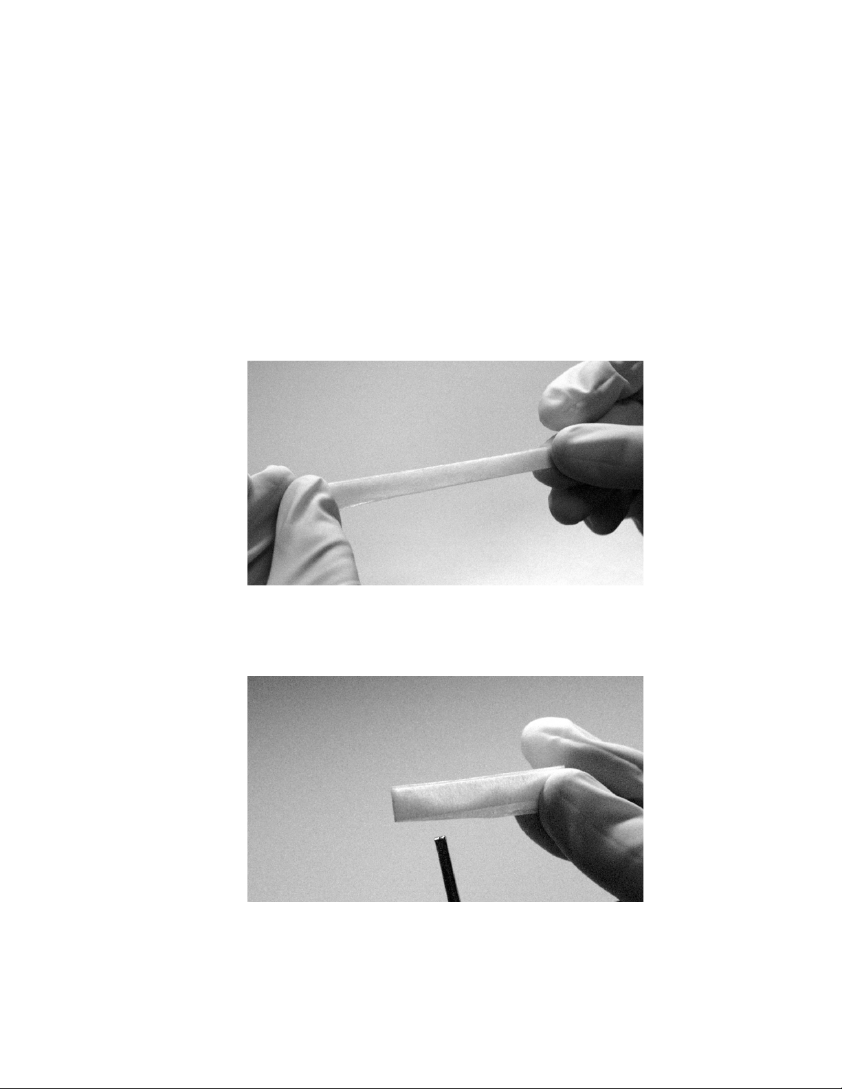
Maintenance and Service
Alternative Cleaning Procedure
As an alternative to the cleanroom swab procedure, use the
following procedure with lens tissue and a hemostat:
1. With one hand on each end of the lens tissue, fold the tissue in
half (width wise), three times. Do not touch any part of the lens
tissue that will make contact with the fiber optic surface. See
Figure 6-13.
2. Use a hemostat to fold the tissue in half, lengthwise. Do not
touch any part of the lens tissue that will be used to clean the
fiber optic surface. See Figure 6-14.
3. Attach a hemostat to the lens tissue as shown in Figure 6-15.
Figure 6-13. Folded Lens Tissue (Width Wise)
Figure 6-14. Folded Lens Tissue (Lengthwise)
6 - 35
Page 94
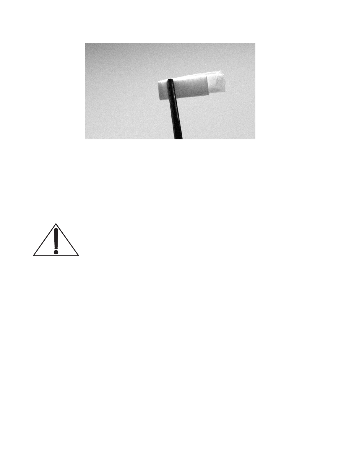
Verdi V-2/V-5/V-6 Laser Operator’s Manual
Figure 6-15. Hemostat Attached to Properly Folded Lens Tissue
4. Using a medicine dropper, put two drops of Methanol on the
lens tissue.
5. Vigorously shake off excess Methanol from the folded tissue
to prevent Methanol residue.
Only the lens tissue should make contact with the fiber optic
surface. Do not allow the hemostat to touch the fiber surface.
6. Holding the fiber vertically so the lens surface points to the
ceiling, carefully place the base of the wet side of the folded
tissue against the fiber optic surface, taking care not to touch
the fiber optic with the hemostat. See Figure 6-16.
7. Drag the folded tissue across the fiber optic surface in a single
stroke. Do not drag the swab back and forth.
8. Repeat Step 7 using the other side of the folded tissue.
9. Re-check the fiber using the fiberscope. If imperfections
remain, repeat the procedure using a new lens tissue.
10. If imperfections still remain, compare the image in the fiberscope with Figure 6-19 and determine whether the fiber optic
must be replaced. Contact Coherent Service if further guidance
is needed.
If the fiber surface is now ideal or complies with the guidelines
as illustrated in Figure 6-19 on page 6-39, immediately install
the fiber optic into the FAP-I/FAP-B.
6 - 36
Page 95
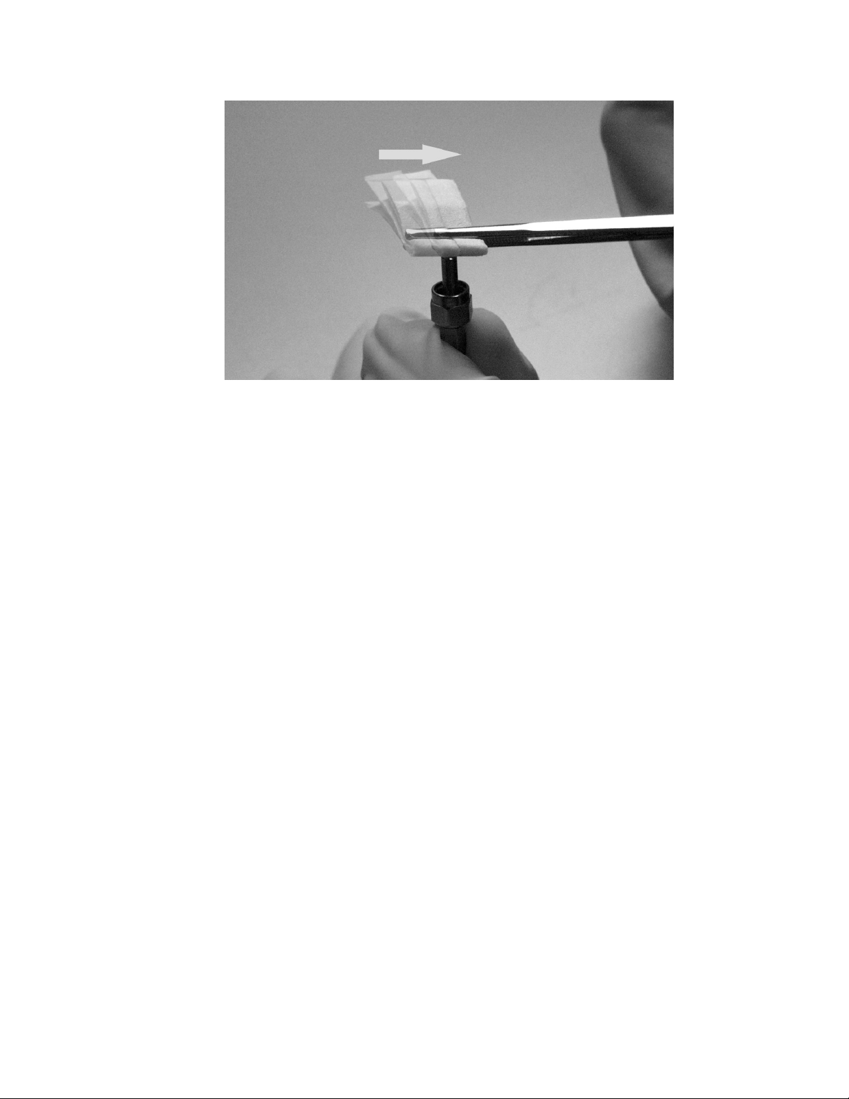
Maintenance and Service
Figure 6-16. Placement and Movement of the Folded Tissue Against the Fiber Optic Surface
Examples of Good and Bad Fibers
Figure 6-17 shows an image of the ideal fiber optic surface that can
be used successfully in the FAP-I/FAP-B assembly through a fiberscope. Figure 6-18 shows images of fibers through a fiberscope with
imperfections that can impair the function of the assembly. The
image on the left is clearly a damaged fiber. Severely damaged fibers
must not be used in the FAP-I/FAP-B assembly or permanent and
severe damage to the assembly will occur.
The image on the right shows a fiber that is questionable. If the
power output is acceptable, then the fiber can be used with little
concern for damaging the assembly. However, if the power output is
unstable or not up to acceptable standards, the fiber must be considered damaged and must not be used.
Figure 6-19 illustrates further criteria for accepting or rejecting a
fiber because of damage. Note that the views shown do not represent
the entire surface of the fiber optic. Much of the surface is the metal
connector and only the 800-micron core is the actual optical fiber.
6 - 37
Page 96
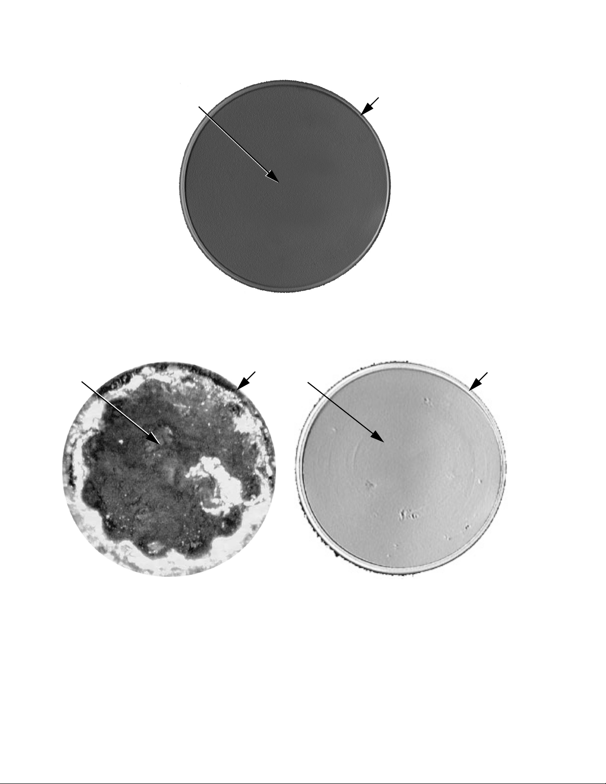
Verdi V-2/V-5/V-6 Laser Operator’s Manual
Core
Core
Figure 6-17. Good Fiber
Cladding
Core
Cladding
Cladding
Bad Fiber (Burned) Questionable Fiber
Figure 6-18. Bad or Questionable Fibers
6 - 38
Page 97
Buffer
Maintenance and Service
Cladding
Core
IDEAL FIBER
Chipped
Fibers
Accept < 3
Particles
Under Coating
ACCEPTABLE IMPERFECTIONS
Cracked
Fibers
Accept
Particles
Outside
Core
>3 Core
Scratches
Scratch
Across Core
Large
Burn mark
Contamination
CRITERIA FOR REJECTION
Figure 6-19. Guidelines for Fiber Optic Inspection
6 - 39
Page 98
Verdi V-2/V-5/V-6 Laser Operator’s Manual
LBO Temperature Optimization
The conversion efficiency of the LBO frequency doubler is heavily
dependent upon temperature. A temperature change of 1°C can
reduce the doubling efficiency by more than 50%. To compensate
for the reduced efficiency, the laser will use more current to produce
the desired 532 nm output. This will reduce the lifetime of the
diodes.
As a solution to this potential problem, the Verdi V-2/V-5/V-6 software contains a menu routine which will perform a LBO temperature optimization automatically to maximize the conversion efficiency of the doubler. The LBO Optimization routine should run
when diode current is observed to be 10% greater than baseline
values.
Note that the shutter is active during the LBO optimization.
Because laser power will change while the routine executes,
Coherent recommends the shutter remains closed throughout
the process.
To find an accurate LBO setpoint temperature, set the output power
level as close to maximum power (depending on system type) as
possible. The routine is designed such that it will not run if the laser
power level is less than 80% of the specified maximum power.
Performing the Optimization
Once the routine is complete, the system will display “LBO optimized” and return the laser to “Light Regulation” mode at the preset
power level.
1. Turn the Verdi on at the maximum power level. Record the
LBO setpoint temperature.
2. Scroll to the LBO Optimization submenu and select the LBO
optimization routine. LBO optimization requires up to 45
minutes to run.
3. Once the routine is complete, record the LBO temperature as
the new baseline value in the system weekly log book.
During optimization, the LBO temperature will increase and
decrease with the software recording the Verdi output power at each
LBO temperature. (This routine is performed with a constant diode
current.)
Optimum LBO temperature will be determined based on the Verdi
Output Power vs. LBO Temperature curve. The new temperature
will be stored as the LBO temperature set point.
6 - 40
Page 99
Maintenance and Service
LBO Error Message
Fuse Replacement
If the system is not able to determine an optimum LBO temperature
the message “TLBO < 2°C Temperature not changed” will be
displayed. If this should occur, contact your local Coherent Service
representative.
Criteria for Replacement
Defective fuse per troubleshooting Charts 1 and 4.
Do not turn the power switch on the rear panel to the OFF position or disconnect the AC power input until the LBO cool down
cycle is complete.
1. Perform the procedure in paragraph titled, “Turn-off
(Complete Shut-down)” on page 4-5. The associated
cool-down cycle will take approximately 30 minutes. The
front panel display will indicate when the cool-down cycle is
complete.
2. Turn the power switch on the power supply rear panel to the
OFF position and disconnect the power cord from facility
power.
A fuse that fails repeatedly is an indication of a more serious
problem. In this case, the system should be returned to the
factory. If the laser system or components are being returned
directly to Coherent, an RMA (Return Material Authorization)
number is required. Contact Coherent or an authorized representative.
3. The location of the fuse is shown on Figure 4-2 on page 4-8.
Insert a small straight-slotted screwdriver and twist
counter-clockwise to remove the fuse holder.
4. Replace the fuse with an appropriate fuse and reinstall the fuse
holder.
5. Connect the power supply power cord to facility power.
6. Perform the procedure in paragraph titled, “Turn-on
(Cold-Start)” on page 4-2.
6 - 41
Page 100
Verdi V-2/V-5/V-6 Laser Operator’s Manual
Verification of Successful Installation
7. The AC ON indicator on the power supply front panel will
light.
Battery Replacement
Preliminary Steps and Data
The backup battery in the laser system power supply must be
replaced as soon as possible after the fault message “Battery
Requires Service” is displayed on the power supply front panel.
Failure to do so may result in damage to the system when coupled
with a loss in AC power.
Do not turn the power switch on the rear panel to the OFF position or disconnect the AC power input until the LBO cool down
cycle is complete.
With AC power off, the power supply must be plugged in at least
every 6 months to allow the battery to charge. Otherwise,
permanent charging capacity loss may occur.
1. With the keyswitch set to the ON position and the system in
“Light Control” operation, set the laser to its specification
output power.
2. Record the following system data from the Temperature Set
Points submenu. See menu titled, “Temperature Set Points” on
page 4-15:
a. LBO temperature set point
b. Vanadate temperature set point
c. Etalon temperature set point
d. Diode #1 temperature set point
3. Record the following system data from the Diode Parameters
Screen submenu. See menu titled, “Diode Parameters Screen”
on page 4-16
a. Diode #1 current (software value).
4. Perform the procedure titled, “Turn-off (Complete
Shut-down)” on page 4-5. The associated cool-down cycle
6 - 42
 Loading...