

Page 1
User Manual
PowerMax™-USB/RS
Sensor System
Page 2

Page 3

User Manual
PowerMax-USB/RS
Sensor System
27650 SW 95th Ave.
Wilsonville, OR 97070
Page 4

PowerMax-USB/RS User Manual
This document is copyrighted with all rights reserved. Under the copyright
laws, this document may not be copied in whole or in part or reproduced in
any other media without the express written permission of Coherent, Inc.
Permitted copies must carry the same proprietary and copyright notices as
were affixed to the original. This exception does not allow copies to be
made for others, whether or not sold, but all the material purchased may
be sold, given or loaned to another person. Under the law, copying
includes translation into another language.
Coherent and the Coherent Logo are registered trademarks of Coherent,
Inc. PowerMax is a trademark of Coherent, Inc. National Instruments and
LabVIEW are trademarks of National Instruments Corporation.
Every effort has been made to ensure that the data given in this document
is accurate. The information, figures, tables, specifications and schematics
contained herein are subject to change without notice. Coherent makes no
warranty or representation, either expressed or implied with respect to this
document. In no event will Coherent be liable for any direct, indirect,
special, incidental or consequential damages resulting from any defects in
its documentation.
Technical Support
In the U.S.:
Should you experience difficulties with your product, or need technical
information, please visit our website: www.Coherent.com
additional support by either telephoning our Technical Support Hotline at
1.800.343.4912, or e-mailing our Support Team at
[email protected]. Telephone coverage is available
Monday through Friday (except U.S. holidays).
If you call outside our office hours, your call will be taken by our answering
system and will be returned when the office reopens.
If there are technical difficulties with your product that cannot be resolved
by support mechanisms outlined above, please e-mail or telephone
Coherent Technical Support with a description of the problem and the
corrective steps attempted. When communicating with our Technical
Support Department, via the web or telephone, the model and serial
number of the product will be required by the Support Engineer responding
to your request.
Outside the U.S.:
If you are located outside the U.S., visit our website for technical
assistance, or telephone our local Service Representative. Representative
phone numbers and addresses can be found on the Coherent website,
www.Coherent.com
.
. You can obtain
Coherent provides web and telephone technical assistance as a service to
its customers and assumes no liability thereby for any injury or damage
that may occur contemporaneous with such services. These support
services do not, under any circumstances, affect the terms of any warranty
agreement between Coherent and the buyer. Operating a Coherent
product with any of its interlocks defeated is always at the operator's risk.
ii
Page 5

Table of Contents
TABLE OF CONTENTS
Preface ................................................................................................................................. vii
RoHS Compliance ............................................................................................................... vii
U.S. Export Control Laws Compliance ............................................................................... vii
Publication Updates .............................................................................................................vii
Symbols Used in This Document ........................................................................................ vii
Safety ...........................................................................................................................................1
Waste Electrical and Electronic Equipment (WEEE, 2002)...................................................1
Declaration of Conformity......................................................................................................2
Description ...............................................................................................................................3
Introduction.............................................................................................................................3
Product Overview ...................................................................................................................3
Product Features ............................................................................................................3
Software Features ..........................................................................................................4
Technical Description .............................................................................................................5
Thermopile Technology .................................................................................................5
Long-Pulse Energy Measurement With a Thermopile .........................................6
Semiconductor Technology ...........................................................................................7
Applying Wavelength Compensation Accuracy.....................................................................9
Operation................................................................................................................................11
LED Status Indicators...........................................................................................................11
PowerMax-USB LED Lights.......................................................................................11
PowerMax-RS LED Lights..........................................................................................12
Powering PowerMax-RS Sensors.........................................................................................12
Extending Cable Length .......................................................................................................12
How to Take a Power Measurement .....................................................................................13
Measuring Power With a PowerMax-USB Thermopile Sensor ..................................13
Measuring Power With a PowerMax-RS Thermopile Sensor .....................................16
Zeroing..................................................................................................................................18
Setting the Wavelength .........................................................................................................18
Using the Software................................................................................................................19
Front Panel...................................................................................................................19
Keyboard Shortcuts.............................................................................................19
Select Sensor.......................................................................................................20
Start/Stop Data Collection ..................................................................................21
Trending Chart....................................................................................................22
Histogram Chart..................................................................................................23
Tuning Chart .......................................................................................................24
Alignment Target Chart ......................................................................................25
Synchronized Trending Chart.............................................................................26
Reset Error ..........................................................................................................28
Graph Palette.......................................................................................................29
iii
Page 6

PowerMax-USB/RS User Manual
Live Reading.......................................................................................................30
Wavelength .........................................................................................................30
Live Data Averaging ...........................................................................................31
Mean ...................................................................................................................31
Min......................................................................................................................32
Counts .................................................................................................................32
Std Dev................................................................................................................33
Max .....................................................................................................................34
Mode ...................................................................................................................34
Sample Collection...............................................................................................35
Sample Size.........................................................................................................35
Zero Sensor .........................................................................................................36
Reset Button........................................................................................................36
Gain Correction...................................................................................................37
Collection Mode .................................................................................................38
Collection Interval ..............................................................................................38
Log Data to File ..................................................................................................39
Log Data File ......................................................................................................39
Menus...........................................................................................................................40
File Menu............................................................................................................40
Settings Menu .....................................................................................................45
View Menu..........................................................................................................47
Window Menu.....................................................................................................49
Help Menu ..........................................................................................................49
Host Interface.......................................................................................................................51
Introduction...........................................................................................................................51
Message Terminators ............................................................................................................52
Messages Received by the Sensor ...............................................................................52
Messages Sent by the Sensor .......................................................................................52
Host Command Quick Reference .........................................................................................53
SCPI Interface Section..........................................................................................................55
Syntax and Notation Conventions ...............................................................................55
Commands and Queries ...............................................................................................56
SCPI Common Commands.................................................................................56
System Options ...................................................................................................56
Error Record Reporting and Collection ..............................................................58
Measurement Setup and Control.........................................................................60
Querying Measurement Data ..............................................................................62
Sensor Information .............................................................................................63
Legacy LaserPAD/SSIM Interface Section...........................................................................65
Commands and Queries ...............................................................................................65
LaserPAD/SSIM Streaming Data Record Format .......................................................69
Data Streaming Transmission Interface Section ...................................................................70
Streaming Measurement Data......................................................................................70
Commands and Queries ...............................................................................................70
Operational Parameters.........................................................................................................71
iv
Page 7

Table of Contents
Calibration and Warranty ...........................................................................................73
Calibration ............................................................................................................................73
Coherent Calibration Facilities and Capabilities ..................................................................73
Limited Warranty ..................................................................................................................74
Extended Warranty................................................................................................................74
Warranty Limitations ............................................................................................................75
Obtaining Service .................................................................................................................75
Product Shipping Instructions...............................................................................................76
Appendix A: Specifications..........................................................................................77
Compatible Sensors ..............................................................................................................77
Appendix B: Troubleshooting and Error Messages.....................................79
Index ..........................................................................................................................................81
LIST OF TABLES
1. Wavelength Compensation Accuracy ................................................................................10
2. PowerMax-USB LED Light Conditions............................................................................11
3. PowerMax-RS LED Light Conditions...............................................................................12
4. Keyboard Shortcuts............................................................................................................19
5. Host Command Quick Reference ......................................................................................53
6. Status Condition Character Definitions .............................................................................56
7. Error Codes and Description Strings .................................................................................58
8. Measurement Data Record Formats ..................................................................................62
9. Flags Character Definitions ...............................................................................................63
10. Measurement Data Record Formats ..................................................................................69
11. Data Streaming Transmission Rates ..................................................................................71
12. Operational Parameters......................................................................................................71
13. Coherent Service Centers...................................................................................................76
14. Compatible Sensors ...........................................................................................................77
LIST OF FIGURES
1. Waste Electrical and Electronic Equipment Label...............................................................1
2. Saturation Power and Minimum Power for PowerMax-USB UV/VIS Quantum Sensor ...8
3. Photo Sensitivity Temperature Characteristics ....................................................................9
4. RV Spectral Correction for Thermal Sensors (Normalized to Calibration Wavelength)...10
5. Front Panel.........................................................................................................................19
6. Drop-Down Menus ............................................................................................................40
7. File Menu...........................................................................................................................40
8. Settings Menu ....................................................................................................................45
9. View Menu.........................................................................................................................47
10. Window Menu....................................................................................................................49
11. Help Menu .........................................................................................................................49
v
Page 8

PowerMax-USB/RS User Manual
vi
Page 9

Preface
Preface
RoHS Compliance
U.S. Export Control Laws Compliance
This manual contains user information for the Coherent
PowerMax™ meterless power sensors and the PowerMax PC software.
This Coherent product is RoHS compliant.
It is the policy of Coherent to comply strictly with U.S. export
control laws.
Export and re-export of lasers manufactured by Coherent are subject
to U.S. Export Administration Regulations, which are administered
by the Commerce Department. In addition, shipments of certain
components are regulated by the State Department under the International Traffic in Arms Regulations.
The applicable restrictions vary depending on the specific product
involved and its destination. In some cases, U.S. law requires that
U.S. Government approval be obtained prior to resale, export or
re-export of certain articles. When there is uncertainty about the
obligations imposed by U.S. law, clarification should be obtained
from Coherent or an appropriate U.S. Government agency.
Publication Updates
Symbols Used in This Document
To view information that may have been added or changed since this
publication went to print, connect to www.Coherent.com.
This symbol is intended to alert the operator to the presence of
dangerous voltages associated with the product that may be of
sufficient magnitude to constitute a risk of electrical shock.
This symbol is intended to alert the operator to the presence of
important operating and maintenance instructions.
vii
Page 10

PowerMax-USB/RS User Manual
viii
Page 11
Safety
SAFETY
Carefully review the following safety information to avoid personal
injury and to prevent damage to this product or any equipment
connected to it. There are no user-serviceable parts in Coherent
PowerMax meterless power sensors. For service information, refer
to “Obtaining Service” on page 75.
Do not operate the system if its panels are removed or any of the
interior circuitry is exposed.
Waste Electrical and Electronic Equipment (WEEE, 2002)
Do not operate the system in wet or damp conditions, or in an
explosive atmosphere.
Do not operate the system if there are suspected failures. Refer
damaged units to qualified Coherent service personnel.
The European Waste Electrical and Electronic Equipment (WEEE)
Directive (2002/96/EC) is represented by a crossed-out garbage
container label (Figure 1). The purpose of this directive is to minimize the disposal of WEEE as unsorted municipal waste and to facilitate its separate collection.
Figure 1. Waste Electrical and Electronic Equipment Label
1
Page 12
PowerMax-USB/RS User Manual
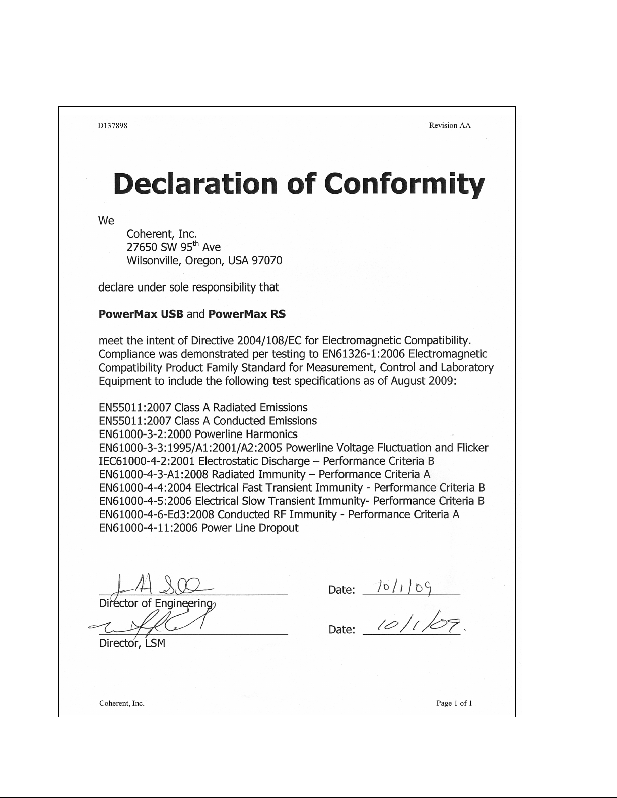
Declaration of Conformity
2
Page 13

DESCRIPTION
Description
Introduction
Coherent PowerMax-USB and PowerMax-RS sensors are the
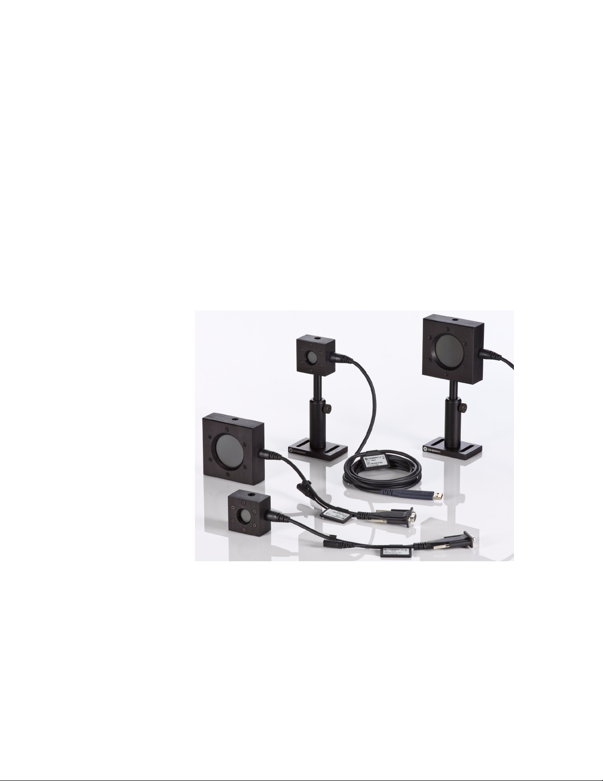
world’s first laser power sensors that utilizes state of the art microelectronics miniaturization techniques and integrate an entire instrument within a USB 2.0 or RS-232 cable connector. Specifically,
PowerMax-USB and PowerMax-RS sensors have all the signal
processing and power measurement electronics normally contained
in a LabMax meter and connect directly to a PC with plug-and-play
functionality. Ideally suited for low- and high-volume embedded
sensor applications, Coherent’s new family of sensors eliminates the
need for a separate meter box, thus delivering a significant savings
in cost and space, but with no reduction whatsoever in performance.
This measurement platform can also be used to measure the energy
in a long laser pulse—typically greater than 1 millisecond in pulse
width—by integrating the output of a thermopile sensor.
Coherent’s PowerMax PC application software provides a virtual
instrument interface for sensors that enable the operator to take laser
power readings, log data, and compute measurement statistics.
Users can also write their own software using host interface
commands that control all aspects of power meter operation.
For the first time, separate electronics are no longer required
between the sensor and a PC. For those customers who can use a PC
for monitoring laser power, these sensors offer significant cost
savings, space savings, and no reduction in performance.
Product Overview
Product Features
PowerMax-USB provides direct USB 2.0 connection to a PC.
•
Power is provided via USB connection.
• PowerMax-RS provides RS-232 connectivity. Power input is
provided by a +5VDC input (power supply is available as an
optional accessory).
• Instrumentation platform is compatible with thermopile and
optical sensors and can be adapted to most power sensors that
Coherent manufactures.
3
Page 14
PowerMax-USB/RS User Manual
• Displays beam position with position-sensing quadrant ther-
• High resolution 24-bit A/D converter supports four digits of
• Sensors include spectral compensation for accurate use at
• Thermopile sensors include a speed-up algorithm that speeds
• LED status indicators inside USB and RS-232 connectors
• Thermopile sensors offer long-pulse joules capability.
mopiles (such as LM-model sensors like the LM-10).
resolution and measurement accuracy equivalent to that found
in Coherent's LabMax meters.
wavelengths that differ from the calibration wavelength. Each
sensor receives a unique spectral compensation curve specific
to the responsivity of its specific element, as well as transmission characterization of any associated optics.
up the natural response of the thermopile detector without
overshoot.
provide health-and-status information.
Software Features
Plug-and-play application software is supplied standard and
includes the following features:
• Trending
• Statistics (mean, minimum, maximum, and standard devia-
tion) and log batch to file.
• Tuning
• Display beam position on position-sensing thermopiles and
log results to file
• Histogram
• Simultaneously operate multiple sensors
4
Page 15

Description
• Perform synchronized ratiometery (A/B analysis). Trend and
log results to file.
• For LaserPAD or SSIM customers, the host command set
includes drop-in compatibility.
For system integrators and for implementations involving
customer-written software, the sensors incorporate a comprehensive
command set that is easy to access:
• Utilized a Window USB driver and supports simple ASCII
host commands for remote interfacing using both
PowerMax-USB and PowerMax-RS sensors.
• Using customer-written software, the remote interfacing host
command set allows sensors to be remotely controlled.
• National Instruments
LabVIEW integration.
™
LabVIEW™ driver is supplied for easy
Technical Description
Thermopile Technology
Thermopile sensors are a great all-purpose technology suitable for
many lasers. They are used for measuring CW laser power, average
power in pulsed lasers, and are often used to integrate the energy of
long pulses. Thermopile sensors absorb incident laser radiation and
convert it into heat. This heat ultimately flows to a heat sink that is
held at ambient temperature by either convection-cooling or
water-cooling. The temperature difference between the absorber and
the heat sink is converted into an electrical signal by a thermocouple
junction.
Thermopiles operate across a wide range of input powers, and unlike
a photodiode-based sensor they will not saturate. The spectral range
is dependent upon the coating applied to absorb the laser power. The
coating used on many thermopiles is broadband in nature and is relatively flat from the ultraviolet through the infrared.
These sensors have natural response times on the order of several
seconds for a low power sensor and up to one minute for a kilowatt
sensor. The exponential nature of the natural thermopile output
allows one to electronically accelerate the voltage to its final value
ahead of the actual sensor signal using a software algorithm. We
typically call this capability a “speed-up” algorithm. When
combined with the PowerMax-USB and PowerMax-RS circuitry, a
5
Page 16
PowerMax-USB/RS User Manual
speed-up algorithm can be applied to provide a much faster
response—on the order of seconds or less for most thermopile
sensors. This feature can be turned on and off in the software.
Coherent has two main types of thermopile sensors:
• The LM Model line utilizes a unique thermopile disk in which
• The PM Model line incorporates traditional thermopile disks
PowerMax-USB and PowerMax-RS sensors can use both types of
sensors.
Long-Pulse Energy Measurement With a Thermopile
the thermocouples are split into four quadrants, allowing the
sensors to provide beam position information in addition to
power measurement.
that provide power measurement without beam position information.
Thermopile sensors are most commonly used for average power
measurements on pulsed and CW lasers. A unique capability of thermopile sensors is the ability to integrate the power of a single “long”
laser pulse (long pulse refers to pulses roughly 1 millisecond up to
several seconds in pulse length). The instrumentation analyzes the
output of the thermopile and applies the integration through the use
of an algorithm that results in a Joules reading. This allows the thermopile to measure the energy of single pulses between 1 millisecond
and 10 seconds in length, and with energies from millijoules to
6
Page 17

Description
hundreds of Joules. The measurement accuracy of this mode is typically better than ± 3% when performed with PowerMax-USB and
PowerMax-RS sensors.
This capability is very useful for what are commonly called
long-pulse medical or industrial type lasers. Common applications
for this type of measurement are in the medical field—especially
skin resurfacing and hair removal—and in material processing
applications, such as laser welding. These laser systems often utilize
high-energy lasers that have large beam sizes and relatively long
pulses.
This type of measurement requires careful selection of the appropriate power sensor, based upon the laser pulse being measured. A
good “rule of thumb” for using a thermopile for this type of
measurement is to compare the maximum pulse energy you need to
measure (in Joules) with the maximum power rating of a sensor (in
Watt s).
Often times a sensor like the PM150-50C is ideal for these measurements. It features a large 50 mm aperture size, can handle pulse energies up to 150J, and can be used air-cooled for single pulse energy
measurements. A PM150-50C normally needs to be water-cooled
for continuous power measurements. The PS19Q sensors, on the
other hand, allow long-pulse measurements down into the mJ level.
Semiconductor Technology
Thermopile joules mode specifications for several PowerMax-USB
and PowerMax-RS sensor can be found in Table 14 on page 77. For
an up-to-date list of all compatible sensors and their specifications,
visit out website: www.Coherent.com/LMC.
Semiconductor photodiode-based sensors convert incident photons
into current that can be measured by our instrumentation. We typically refer to these devices as optical sensors or quantum sensors.
The photodiodes used in these types of sensors offer high sensitivity
and low noise, enabling them to detect very low light levels. The
UV/VIS optical sensor in the PowerMax-USB line is designed to
measure power of CW sources, as well as the average power of
pulsed sources, as long as the repetition rate is above 100 pps. Photodiodes also have a fast response time, making this senor convenient
for tuning and peaking lasers.
These types of sensors have several orders of magnitude higher
sensitivity than thermopile sensors and are quite stable. They do,
however, suffer from photocurrent saturation. The UV/VIS sensor
incorporated into the PowerMax-USB product line includes an
attenuating filter that allows the sensor to be used into the hundreds
7
Page 18

PowerMax-USB/RS User Manual
of milliwatt level without saturation. This ND filter, and the light
shield threaded onto the front of the sensor, also help to block stray
light, thereby resulting in a lower noise floor.
We incorporate spectral compensation in the PowerMax-USB and
PowerMax-RS UV/VIS sensor to provide accurate measurements
across the 325 to 1065 nm spectrum. Because the spectral response
of the ND filter and photodiode varies significantly across this
wavelength range, it is important to check the maximum measurable
power at the wavelength of use to make sure the sensor is not being
saturated. Figure 2, below, indicates the maximum and minimum
measurable power levels by wavelength.
The following curve plots the maximum measurable power—which
is the saturation level of the photodiode—as well as the minimum
recommended power level, by wavelength.
Figure 2. Saturation Power and Minimum Power for PowerMax-USB UV/VIS Quantum Sensor
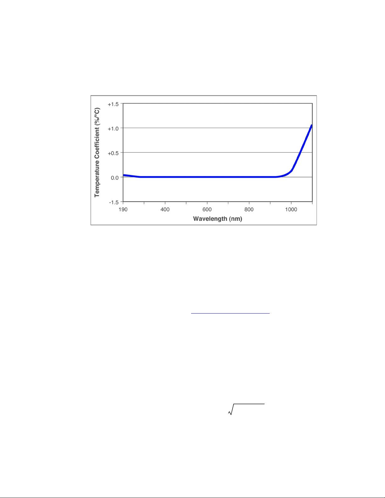
UV/VIS Temperature Linearity: Like all silicon photodiodes, the
UV/VIS Quantum sensor has temperature sensitivity in the infrared
region. At 1064 nm, for example, it has a 0.5%/ºC thermal coefficient. Due to the electronics inside the sensor, measurement error of
up to 2% is present at 1064 nm after a 10-minute warm-up time.
Additional error can be present if the ambient measurement environment differs from the calibration wavelength listed on the calibration
certificate.
8
Page 19
Description
In practice, wavelengths shorter than 1000 nm have insignificant
effects due to temperature.
The following figure references the thermal coefficient at the wavelength of use.
Figure 3. Photo Sensitivity Temperature Characteristics
Applying Wavelength Compensation Accuracy
Overall measurement accuracy is a combination of:
• Calibration uncertainty. Note: Specifications for several
sensors are available in Table 14 on page 77. For an up-to-date
list of all compatible sensors and their specifications, visit out
website: www.Coherent.com/LMC.
• Wavelength compensation accuracy (refer to Table 1 on
page 10).
The combined accuracy is based upon practices outlined in the
National Institute of Standards Guidelines for Evaluating and
Expressing Uncertainty (NIST Technical Note 1297, 1994 Edition).
The combined accuracy of the measurement is calculated by using
the law of propagation of uncertainty using the
“root-sum-of-square” (square root of the sum of squares), sometimes described as “summing in quadrature” where:
Measurement Accuracy =
U
2
2
W
+
where:
U = Percent Calibration Uncertainty
W = Wavelength Accuracy
9
Page 20
PowerMax-USB/RS User Manual
Example:
PowerMax-USB LM-10 used at 1064 nm
U = 2%
W = 1.5%
Measurement Accuracy = %
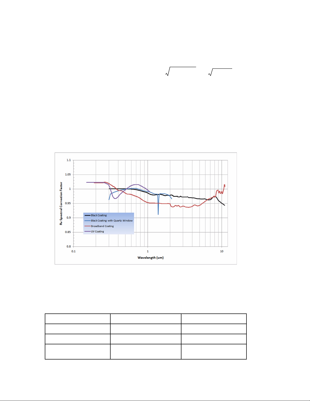
Coherent uses three primary coatings to capture the incident radiation on our thermal sensors. The specifications for each sensor list
which coating is used. Typical wavelength ranges and response
curves for these coatings are shown in Figure 4, below. Each sensor
contains a spectral curve generated from reflectance measurements
taken with spectrometers. The reflectance data are converted into a
wavelength compensation look-up table that is loaded into the
sensor. This data is accessed by selecting a wavelength of operation
in the software.
2
2
2
1.5
+ 42.3+ 2.5==
Figure 4.
All PM- and LM-model thermopiles ± 1.5% 10600
PS model ± 1.5% 514
UV/VIS optical model ± 4% (325 to 900 nm)
a. Refers to wavelengths other than the calibration wavelength.
RV Spectral Correction for Thermal Sensors (Normalized to Calibration Wavelength)
Table 1 lists the spectral compensation accuracy for each type of
sensor.
Table 1. Wavelength Compensation Accuracy
SENSOR
Wavelength Compensation Accuracy
± 5% (900 to 1065 nm)
10
a
CALIBRATION WAVELENGTH (nm)
514
Page 21

OPERATION
In this section:
• LED status indicators (this page)
• Powering PowerMax-RS sensors (page 12)
• Extending cable length (page 12)
• How to take a power measurement (page 13)
• Zeroing (page 18)
• Setting the wavelength (page 18)
• Using the software (page 19)
Operation
LED Status Indicators
Blue LED lights are contained within the PowerMax-USB and
PowerMax-RS connectors to provide health-and-status information.
PowerMax-USB LED Lights
Blue LED
Table 2. PowerMax-USB LED Light Conditions
LED LIGHT CONDITION STATUS
No light visible If the PowerMax-USB sensor is connected to the PC but there are no visible lights, the sensor is not
powering up properly. Test the sensor on another USB port and if that does not solve the problem, contact
Coherent for service (refer to Table 13 on page 76 for contact information).
Lights flashing slowly (0.5 Hz) Sensor is functioning; however, the driver has not been properly loaded. First, make sure power is being
properly applied to the USB port. If that does not solve the problem, remove the sensor from the USB port
and reinstall the software from the CD that shipped with the product (or download the latest software from
our website: www.Coherent.com
).
Blue LED
Lights slowing ramping up and
down in intensity
Lights flashing fast (10 Hz) The sensor is taking power measurements and sending data over the host port.
Sensor is functioning and the driver has been properly loaded.
11
Page 22
PowerMax-USB/RS User Manual
PowerMax-RS LED Lights
Table 3. PowerMax-RS LED Light Conditions
LED LIGHT CONDITION STATUS
No light visible If + 5VDC has been applied to the PowerMax-USB sensor but there are no visible lights in the connector,
the sensor is not powering up properly. Contact Coherent for service (refer to Table 13 on page 76 for
contact information).
Blue LEDs
Lights slowing ramping up and
down in intensity
Lights flashing fast (10 Hz) The sensor is taking power measurements and sending data over the host port.
Powering
PowerMax-RS
Power has been applied to the sensor and it is functioning.
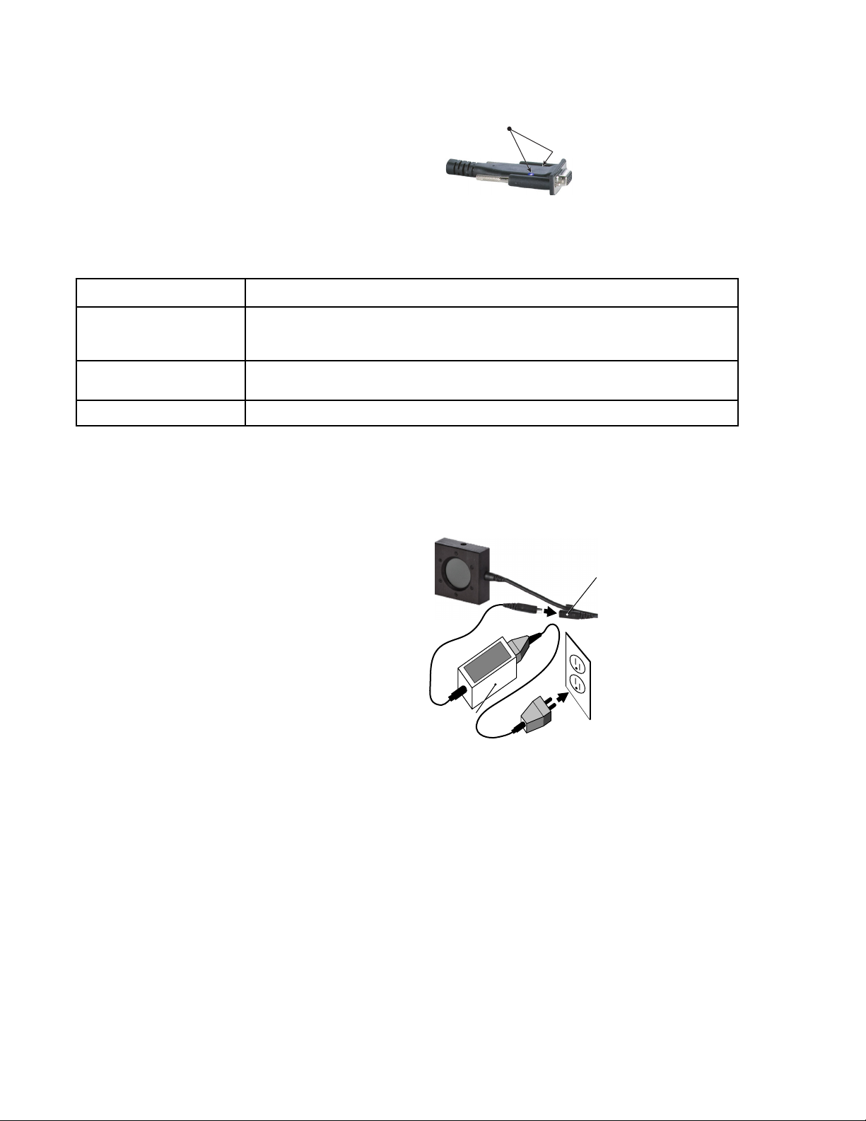
The PowerMax-RS sensor is powered via a +5 VDC power supply
input.
Sensors
Sensor power cable
Power supply
Extending Cable Length
USB sensors: The PowerMax-USB cable is 2.5 meters in length.
USB hubs can be employed to extend the length of the cable. The
USB standard allows for up to five hubs—connected in series with
5-meter cables connecting the hubs—thus providing a maximum
range of 27.5 meters.
There are also active 5-meter USB extension cables on the market
that perform as if they were a USB hub, but for just a single USB
sensor. (Feel free to contact Coherent for advice related to particular
hubs we have tested in-house.)
12
Page 23
Operation
RS sensors: The RS cable is 300 mm in length. It is intended to be
used with a standard off-the-shelf RS-232 extension cable to extend
the length.
How to Take a Power Measurement
This section presents two “mini-tutorials” that explain how to
connect a PowerMax-USB or PowerMax-RS sensor to your PC and
begin taking measurements using the PowerMax PC software.
For instructions on communicating with the sensor directly via
host commands, refer to “Host Interface” on page 51.
Tutorials include:
• Measuring power with a PowerMax-USB thermopile sensor.
• Measuring power with a PowerMax-RS thermopile sensor.
Follow all laser safety procedures. The laser must be switched
OFF or shuttered before running the tutorials presented in this
section.
Measuring Power With a PowerMax-USB Thermopile Sensor
This tutorial describes how to take a power measurement using a
PowerMax-USB thermopile sensor.
Verify the laser is switched OFF or shuttered before starting this
tutorial.
1. Install the PowerMax PC software (for detailed installation
instructions, refer to the PowerMax-USB/RS Software Instal-
lation and Quick Start Guide—part number 1169931—that
shipped with your system).
13
Page 24
PowerMax-USB/RS User Manual
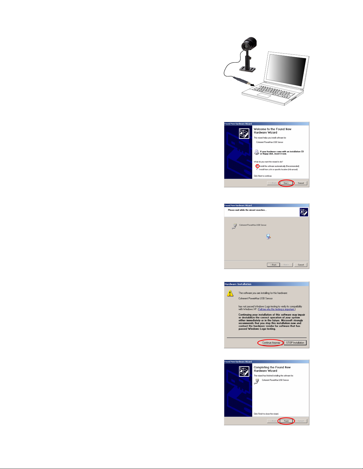
2. Plug in the PowerMax-USB
3. When the Found New
sensor.
Hardware Wizard screen
appears, click “Install the
software automatically
(Recommended)” and
then click the Next button
to continue.
This screen display while the
installation program searches for
the PowerMax-USB sensor.
4. Click the Continue Anyway
button to proceed with the
installation.
5. Click Finish to complete the
installation.
14
Page 25
Operation
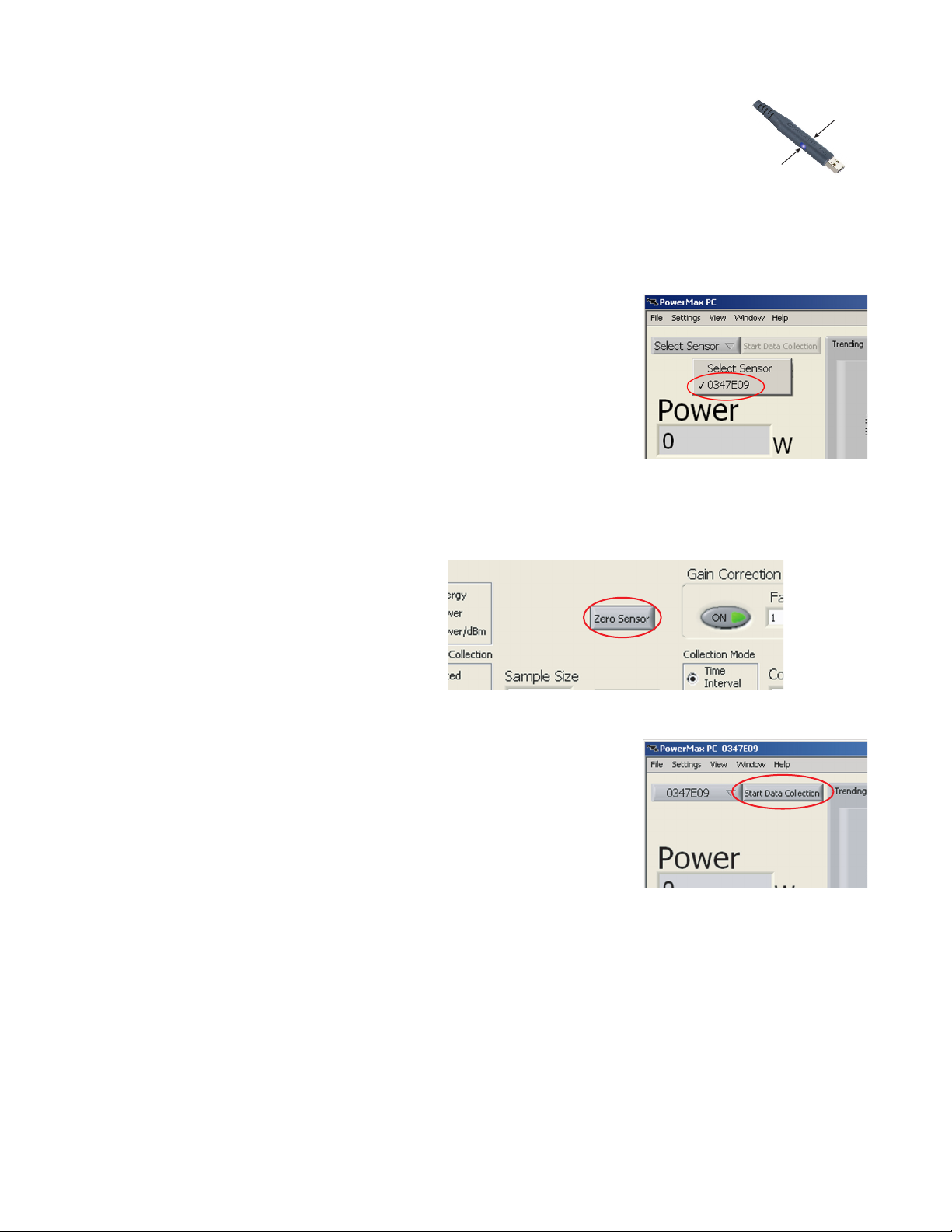
6. Confirm the blue LEDs on the USB
Blue LED
connector are lit and slowly ramping up
and down in intensity (which signifies
the sensor is working and the driver is
Blue LED
properly loaded).
7. Run the PowerMax PC software.
8. Select the sensor serial
number from the Select Sensor
dropdown menu. In the
example at right, the selected
sensor serial number is
0347E09.
9. Press the Zero Sensor button to zero out any offset in the
sensor.
10. Press the Start Data Collec-
tion button and then turn ON
the laser to begin taking
power measurements.
15
Page 26
PowerMax-USB/RS User Manual
Measuring Power With a PowerMax-RS Thermopile Sensor
This tutorial explains how to take a power measurement using a
PowerMax-RS thermopile sensor.
Verify the laser is switched OFF or shuttered before starting this
tutorial.
1. Install the PowerMax PC software (for detailed installation
instructions, refer to the “Software Installation” section of the
PowerMax-USB/RS Software Installation and Quick Start
Guide—part number 1169931—that shipped with your
system).
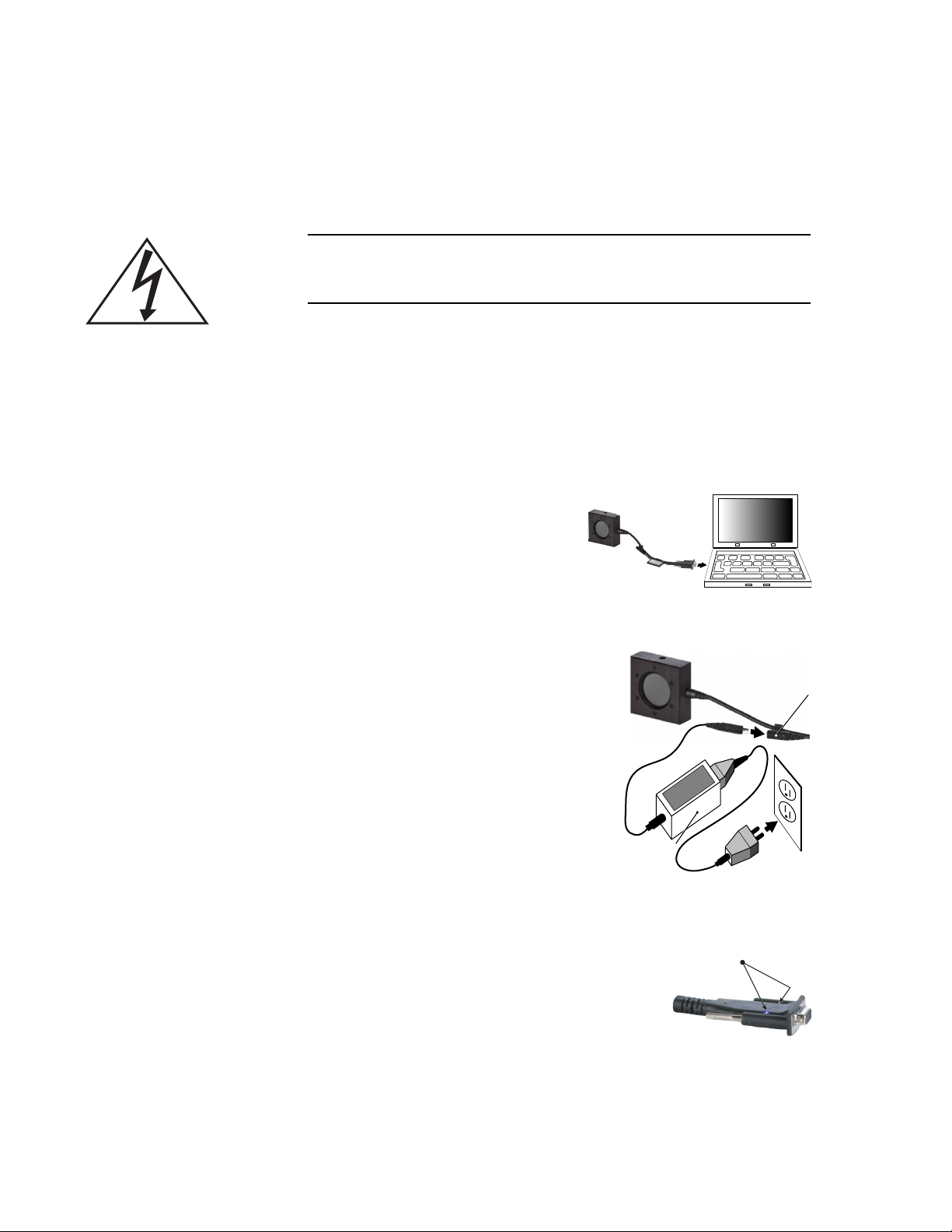
2. Plug the PowerMax-RS
sensor into an available
RS-232 COM port on the
computer.
3. Plug the +5V DC power supply
cable into the sensor power cable
and the power supply into a wall
electrical outlet. (The power
supply is available from Coherent
as an optional accessory—part
number 1105557.)
Power supply
4. Confirm the blue LEDs on the RS
connector are lit and slowly ramping up
and down in intensity (which signifies the
sensor is working and the driver is properly loaded).
5. Run the PowerMax PC software.
Sensor power cable
Blue LEDs
16
Page 27
Operation
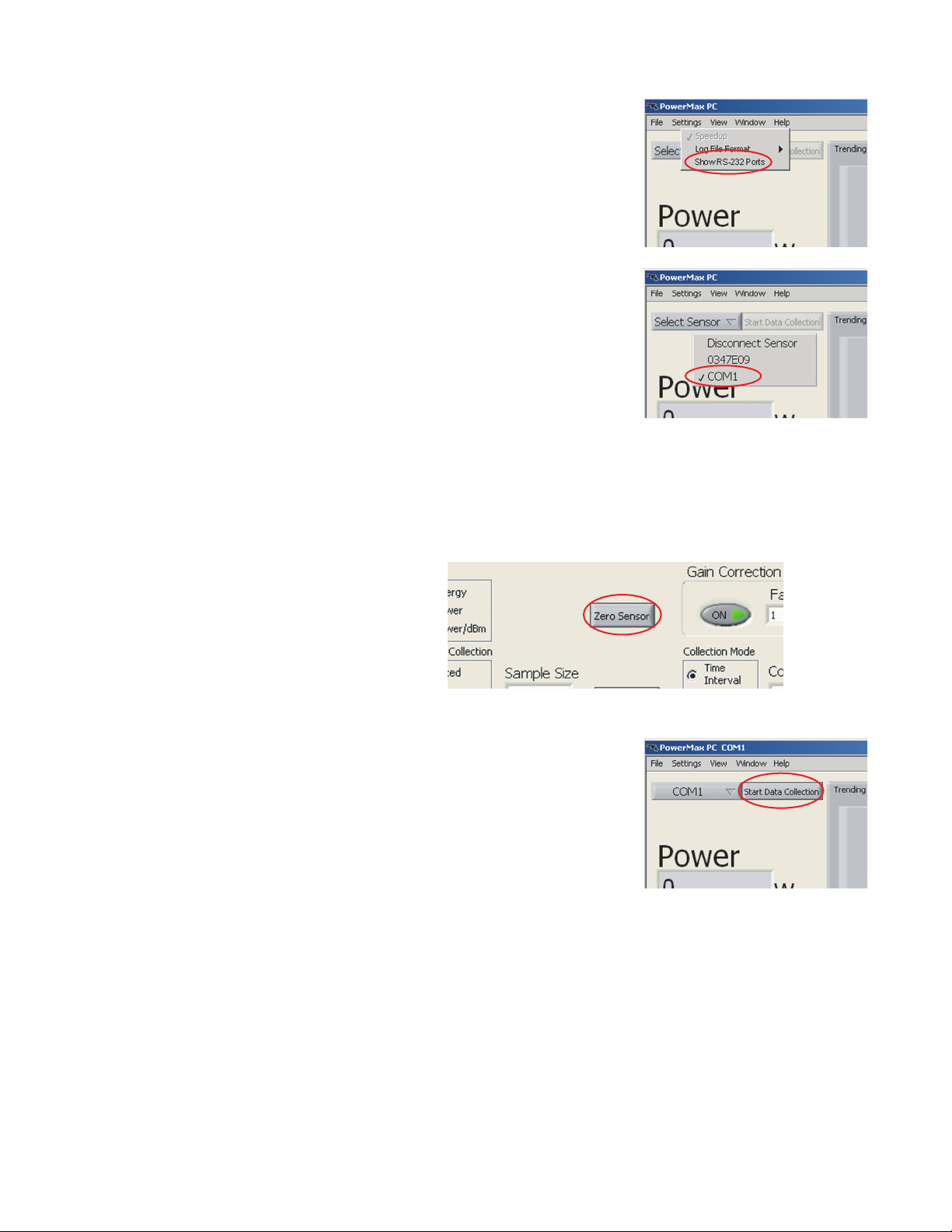
6. Click Show RS-232 Ports
from the Settings dropdown
menu. The software will scan
COM ports for PowerMax-RS
sensors.
7. Select the COM port to which
the PowerMax-RS sensor is
attached. In the example at
right, the selected COM port is
COM1.
8. Insert the sensor into the beam path, making sure the laser is
turned OFF or shuttered until the sensor is zeroed.
9. Press the Zero Sensor button to zero out any offset in the
sensor.
10. Press the Start Data
Collection button and then
turn ON the laser to begin
taking power measurements.
17
Page 28

PowerMax-USB/RS User Manual
Zeroing
Pressing the Zero button implements the Zero function and sets the
current sensor input as the baseline for future measurements. It is
recommended that you zero the sensor after first turning it on and
before beginning any new set of power measurements.
When a zero procedure is in process, no other button events are
queued or activated until the procedure ends. The zero procedure
immediately terminates if the sensor is disconnected or if an error is
encountered.
Normally you should press the Zero button while the laser is turned
off, or while the laser beam is blocked. If a finite power level is
present at the sensor, the instrumentation will attempt to null it out.
The sensor can only zero a finite level of offset equivalent to approximately 10% of full scale range.
If zeroing is unsuccessful—which means that the power input is
too large to null—re-zero in a more stable environment or select
a different range.
Setting the Wavelength
The wavelength should always be set for accurate power measurements. This can be done either in the PowerMax PC application software or over the host port via a host command.
18
Page 29
Using the Software
Operation
Front Panel
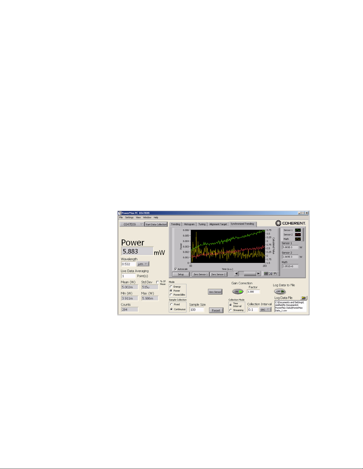
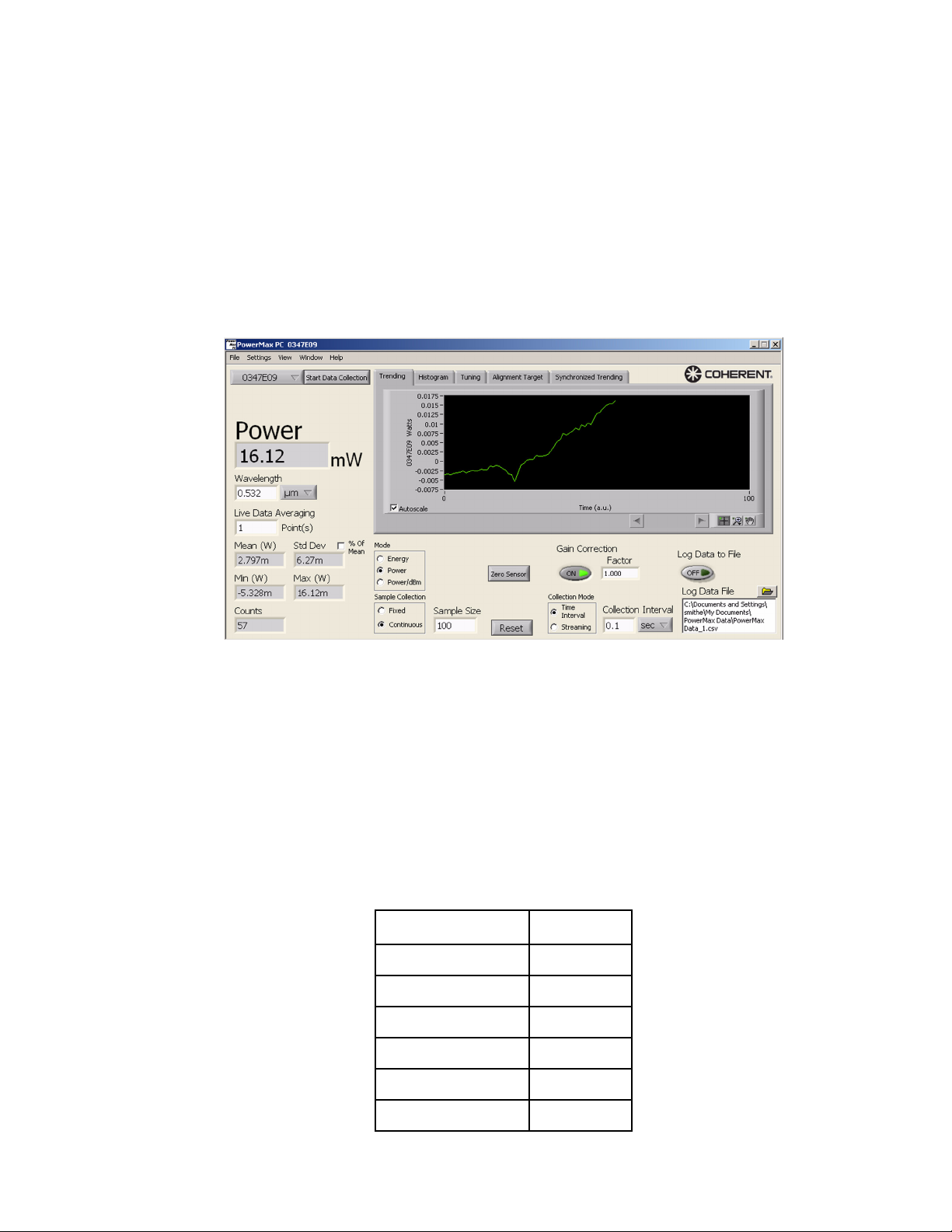
The Front panel (shown in Figure 5) is the first screen that appears
once the software is launched. From here you can enter parameters,
select modes, change ranges, start/stop data acquisition, and view
the output in a chart format.
Figure 5. Front Panel
Individual functions accessed through the Front panel are discussed,
starting next.
Keyboard Shortcuts The following table shows available shortcuts for several standard
functions:
Table 4. Keyboard Shortcuts
FUNCTION SHORTCUT
Exit program <Ctrl>+<Q>
Open new Front panel <Ctrl>+<N>
Print window <Ctrl>+<P>
Show context help <Ctrl>+<H>
View full application <Ctrl>+<F>
View saved data file <Ctrl>+<V>
19
Page 30
PowerMax-USB/RS User Manual
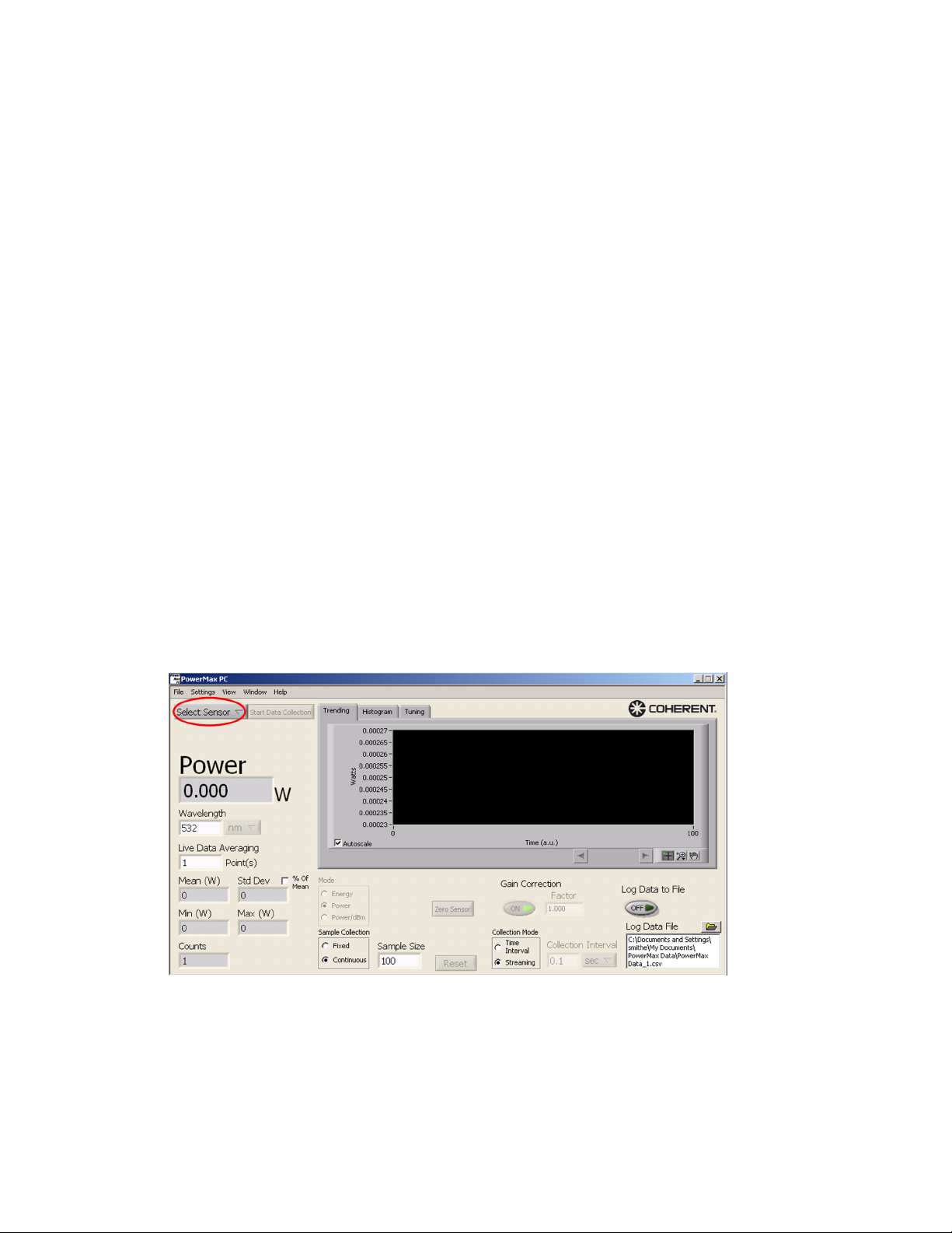
Select Sensor Lists all the connected PowerMax sensors that can be selected for
use by the current Front panel.
The serial numbers of all attached PowerMax sensors are shown in
the dropdown menu, with the visible serial number indicating which
sensor is the current data source.
(USB sensors) The serial numbers of all attached PowerMax-USB
sensors are shown in the dropdown menu, with the visible serial
number indicating which sensor is the current data source.
(RS sensors) RS-232 COM port numbers will appear in the dropdown menu if RS-232 ports are enabled on the Settings dropdown
menu.
Notes:
• After attaching a sensor, it may take several seconds for the
serial number to appear on the list.
• Sensors connected to your computer but already controlled by
a Front panel will appear grayed out (not selectable) in the
Select Sensor dropdown list. If you de-select a sensor in a
Front panel, the Select Sensor dropdown list automatically
updates and that sensor will then be available for selection.
• By default, RS-232 ports do not automatically appear on this
dropdown menu.
20
Page 31
Operation
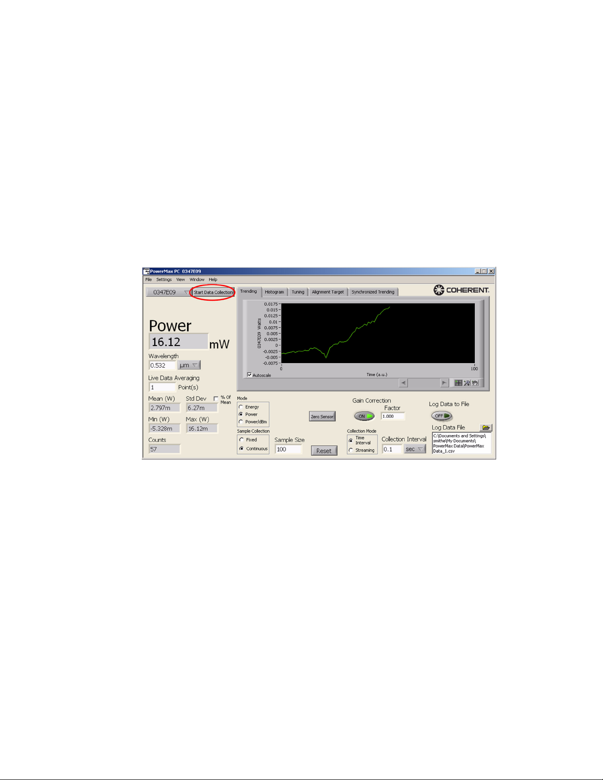
Start/Stop Data Collection
Enables/disables sample collection, including:
• The Trending chart
• Synchronized trending, if enabled
• The Histogram chart
• The Tuning chart
• The Position indicator
• The Reading indicator
• All statistic indicators
• Data logging, if active
21
Page 32
PowerMax-USB/RS User Manual
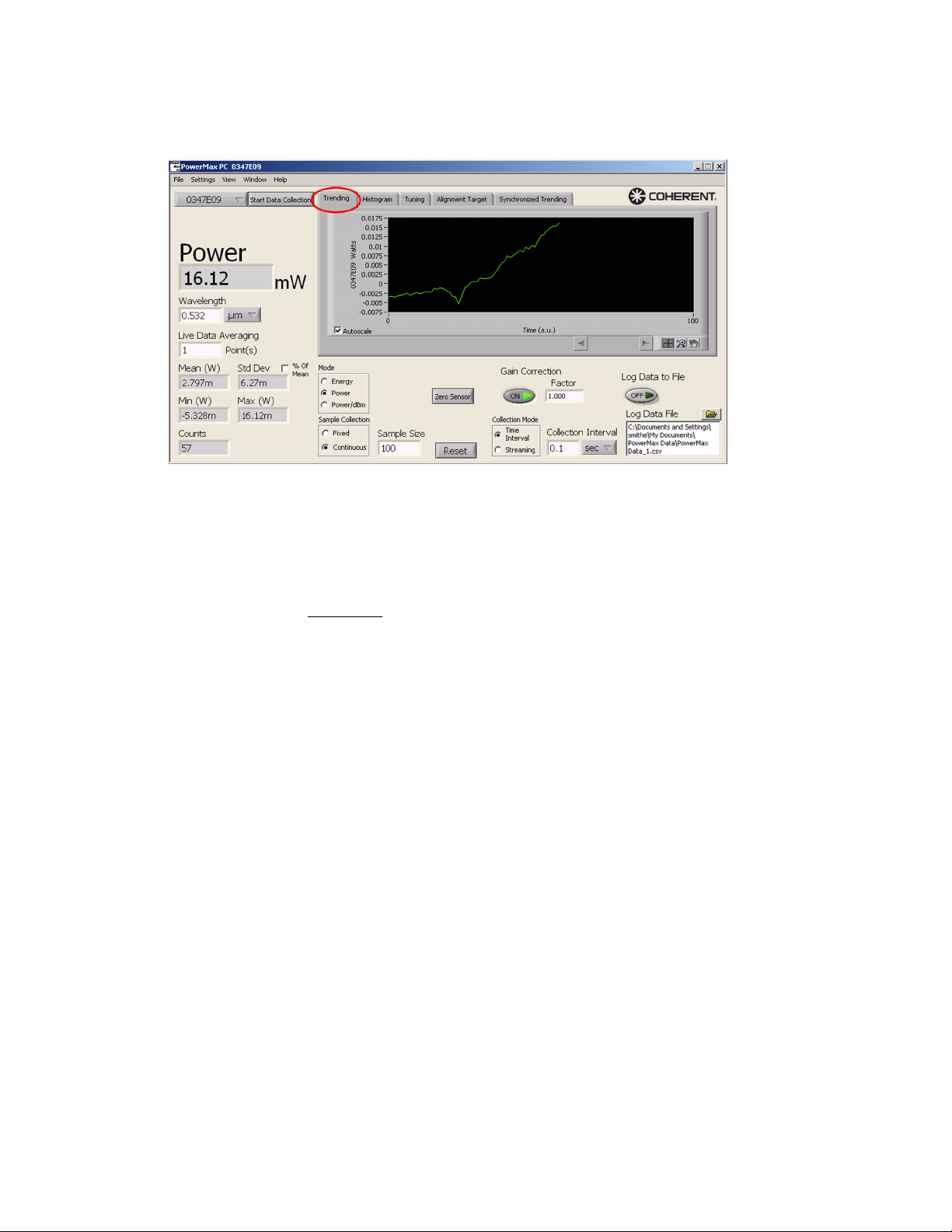
Trending Chart Displays the data received from the PowerMax sensor.
The axis scale points—(x) and (y)—can be directly edited by
clicking on them and entering the desired value. Example: Clicking
on the first x-axis point and setting it to 0 (zero) displays the data
from beginning to present.
Autoscale
• Checked: Y-axis Autoscale is active.
• Unchecked: The graph displays the y-axis in fixed scale.
22
Page 33
Operation
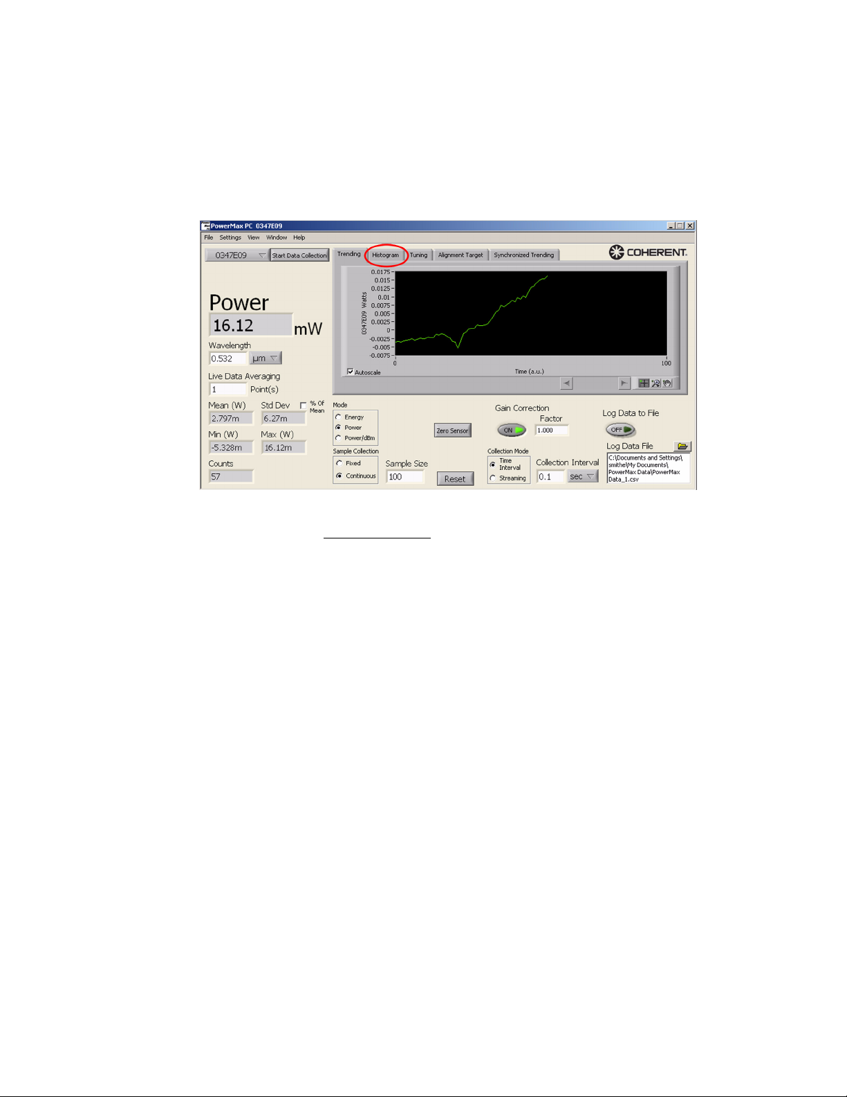
Histogram Chart Displays a histogram of measurement values in the sample buffer.
The sample buffer is controlled by the Sample Size. For example,
with a sample size of 100, up to 100 samples are used in the histogram. Once more than 100 samples have been collected, only the
100 most recent samples are displayed.
Number of Bins
Sets the number of bins along the x-axis used to plot the histogram
data.
23
Page 34
PowerMax-USB/RS User Manual
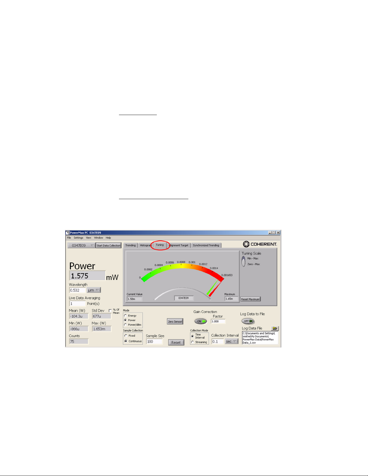
Tuning Chart Displays two values on the Tuning meter:
• Green pointer = current measurement value (also displayed as
a value in the Current Value window at the bottom left of the
Tuning chart)
• Red pointer = maximum measured value (also displayed as a
value in the Maximum window at the bottom right of the
Tuning chart)
Tuning Scale
Use this button to select the scaling range of the Tuning meter.
• Min - Max: Sets the low end of the scale range to the minimum
value in the current data set and the high end of the scale range
to the highest value measured since the last reset.
• Zero - Max: Sets the low end of the scale to zero and the high
end of the scale to the highest value measured since the last
reset.
Reset Maximum Button
Click to reset the maximum value.
24
Page 35
Operation
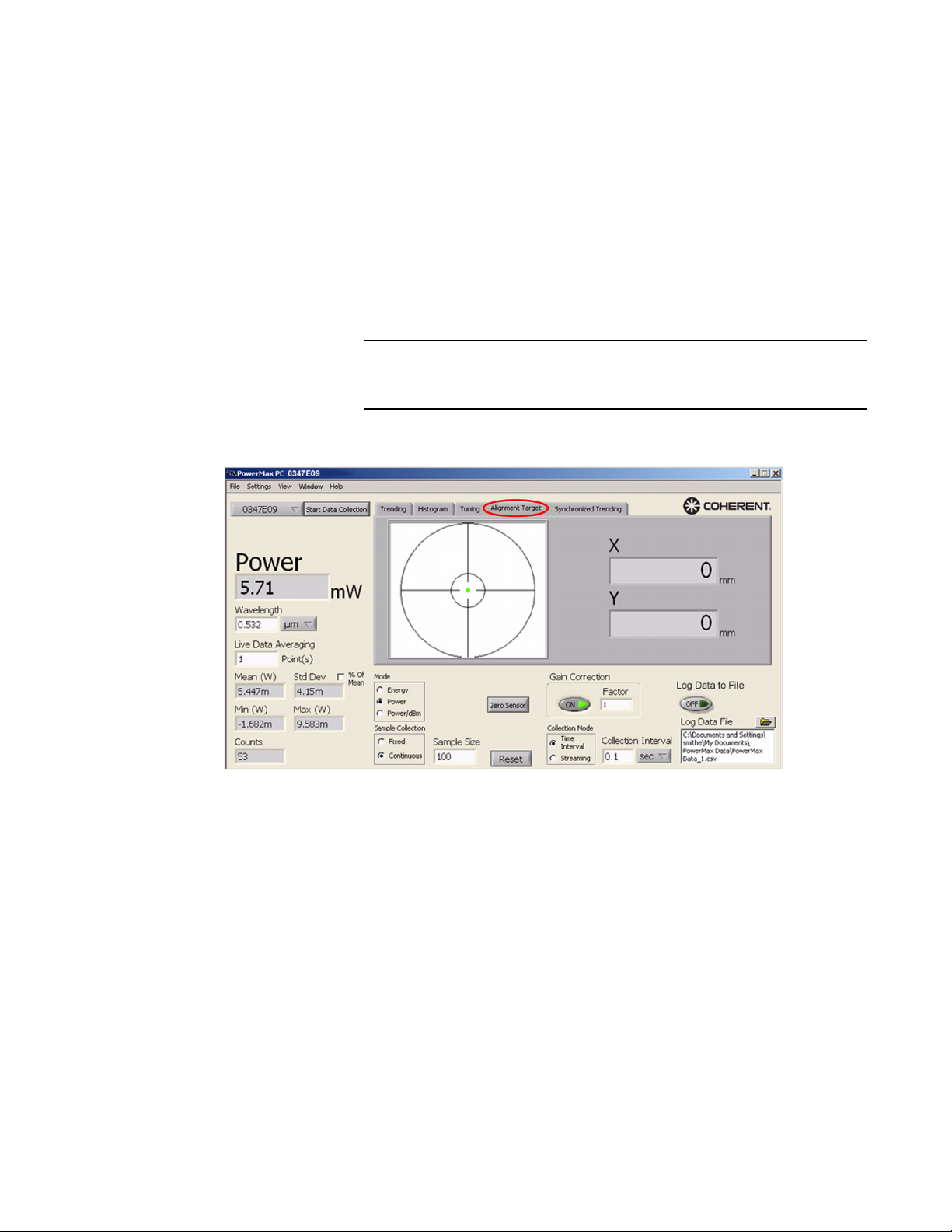
Alignment Target Chart
(Position-sensing thermopile sensors only)
The target represents the bull's-eye view of the laser beam position
of the selected sensor. Position values are scaled and the outer ring
refers to the aperture radius.
The dot on the target represents the position of the beam on the
surface of the sensor. As the beam nears the edge of the aperture, the
dot will display near the edge of the bull's-eye. This feature is useful
when setting up the sensor for a measurement, especially with
non-visible laser beams.
The Alignment Target tab only appears if a thermopile quad
sensor is selected as the current data source.
25
Page 36
PowerMax-USB/RS User Manual
Synchronized Trending Chart
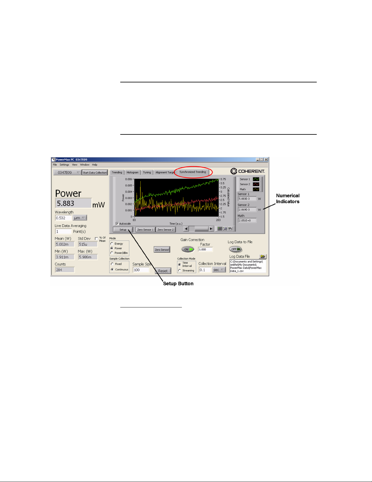
When multiple sensors are available, this tab provides synchronized
plotting of two sensors on the same chart. This screen also provides
the option of performing math—such as ratiometry (A/B)—using
two sensors.
The Synchronized Trending tab only appears if two
PowerMax-USB sensors are available for control by the application. If you have two sensors connected—but two windows
open—the Synchronized Trending tab will not be visible until
you close one of the two windows.
Numerical Indicators
These numerical indicators display the latest readout of both sensors
(in Watts, Joules, or dBm, depending on measurement mode), as
well as the optional synchronized calculated math value, if synchronized data collection is enabled.
26
Page 37
Operation
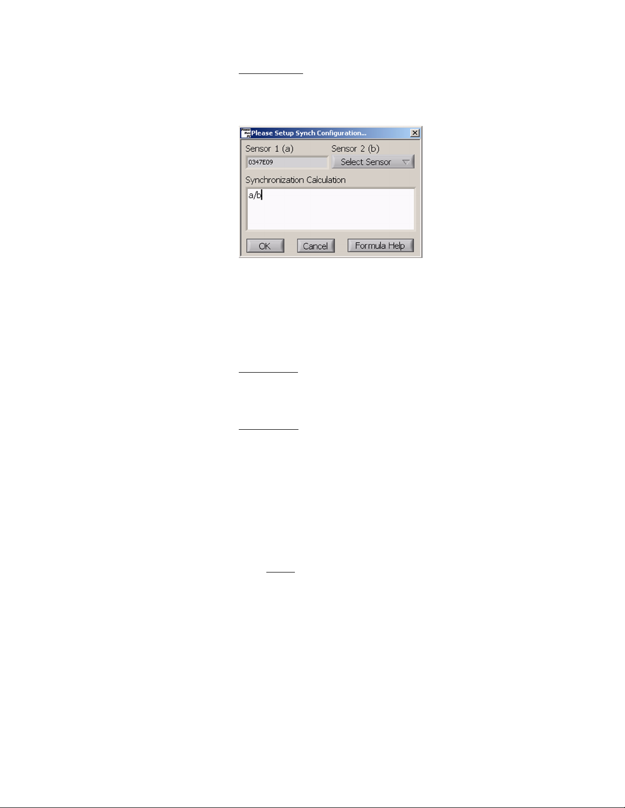
Setup Button
Clicking the Setup button displays the following screen:
Options on this screen include:
• Selecting/deselecting the second sensor to be used for
synchronized data collection
• Changing the Synchronization Calculation equation.
Sensor 1 (a)
Lists the serial number of the primary PowerMax sensor in use by
the current Front panel.
Sensor 2 (b)
Lists all the connected PowerMax sensors that can be selected for
synchronized trending use by the current Front panel.
• (USB sensors) The serial numbers of all available attached
PowerMax-USB sensors are shown in the dropdown menu.
• (RS sensors) RS-232 COM port numbers will not appear in the
dropdown menu because RS-232 sensors do not support
synchronized data collection.
Notes
• After attaching a sensor, it may take several seconds for
the serial number to appear on the list.
• Sensors connected to your computer but already
controlled by a Front panel will not appear in the Sensor
2 (b) dropdown list. If you de-select a sensor in a Front
panel, the Sensor 2 (b) dropdown list automatically
updates and that sensor will then be available for selection.
27
Page 38
PowerMax-USB/RS User Manual
Synchronization Calculation
Lists the current formula used for math calculation on synchronized
data. To change the formula, type the new formula into the Synchro-
nization Calculation field—using the letter “a” to reference Sensor
1 and letter “b” to reference Sensor 2. An error dialog will appear if
an invalid formula is entered.
Zero Sensor 1 Button
Click the Zero Sensor 1 button to zero the main sensor. Clicking on
this button has the same effect as clicking on the main Zero Sensor
button.
Zero Sensor 2 Button
Click the Zero Sensor 2 button to zero the second, synchronized
sensor.
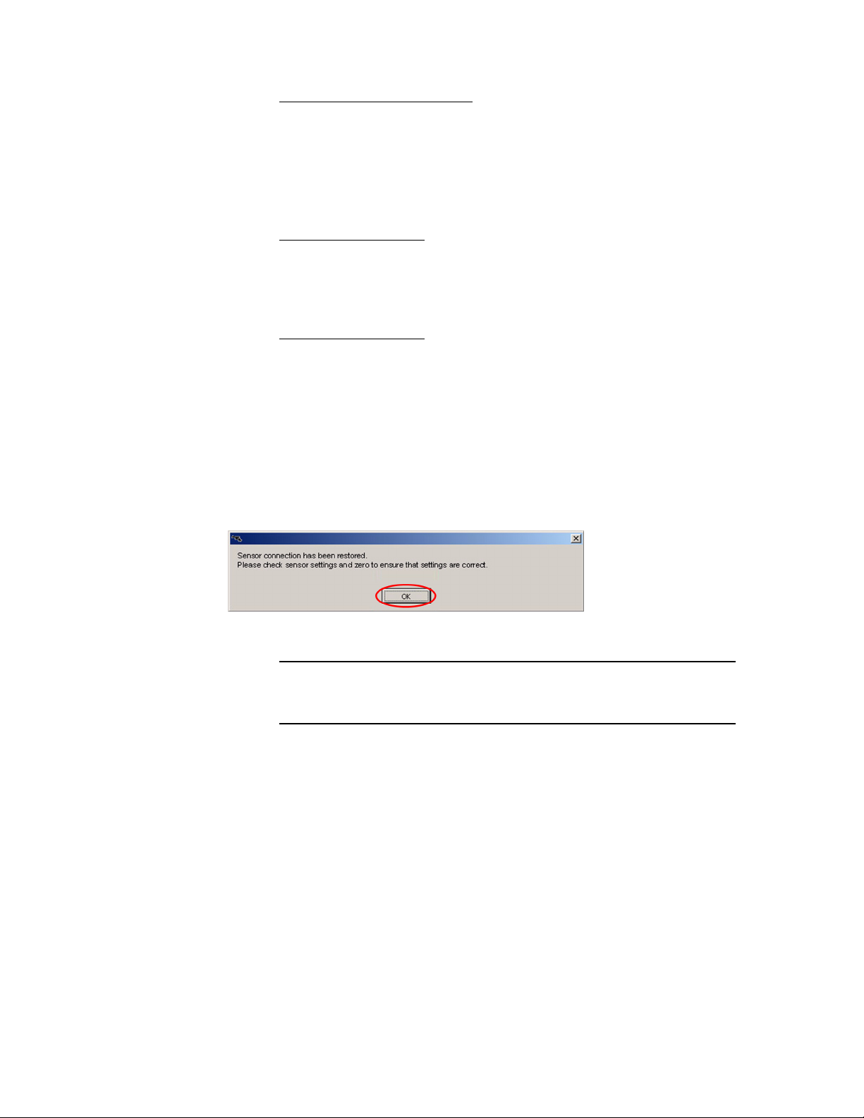
Reset Error A separate error dialog window appears whenever a user action
generates an error. This window will list the possible cause of the
error, as well as other information. Here is an example:
You have to click the OK button in the error dialog window
before new commands can be accepted.
28
Page 39
Operation
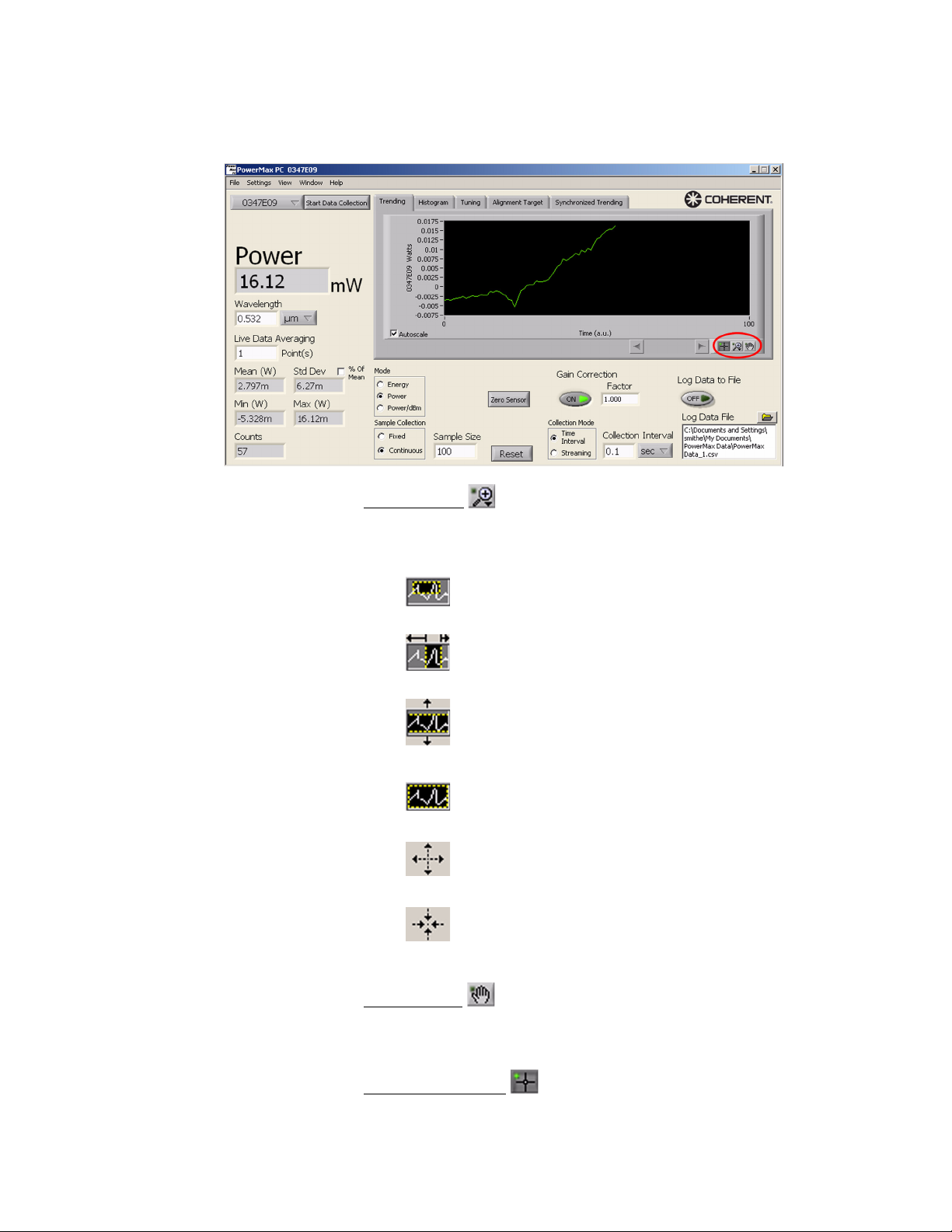
Graph Palette Allows you to zoom or move the plot displayed in the Trending
chart.
Zoom Button
Click this button and then click an option button from the dropdown
list to do any of the following actions:
• Drag the mouse to define the rectangular plot area that
will be displayed in the chart.
• Drag the mouse to define the horizontal plot area that
will be displayed in the chart.
• Drag the mouse to define the vertical plot area that will
be displayed in the chart.
• Click this button to display all data points that have been
collected.
• Click this button and then click anywhere on the chart
to zoom in.
• Click this button and then click anywhere on the chart
to zoom out.
Move Button
Click this button and then drag the mouse on the screen to move the
plot in any direction.
(undefined) Button
This button is currently not used.
29
Page 40
PowerMax-USB/RS User Manual
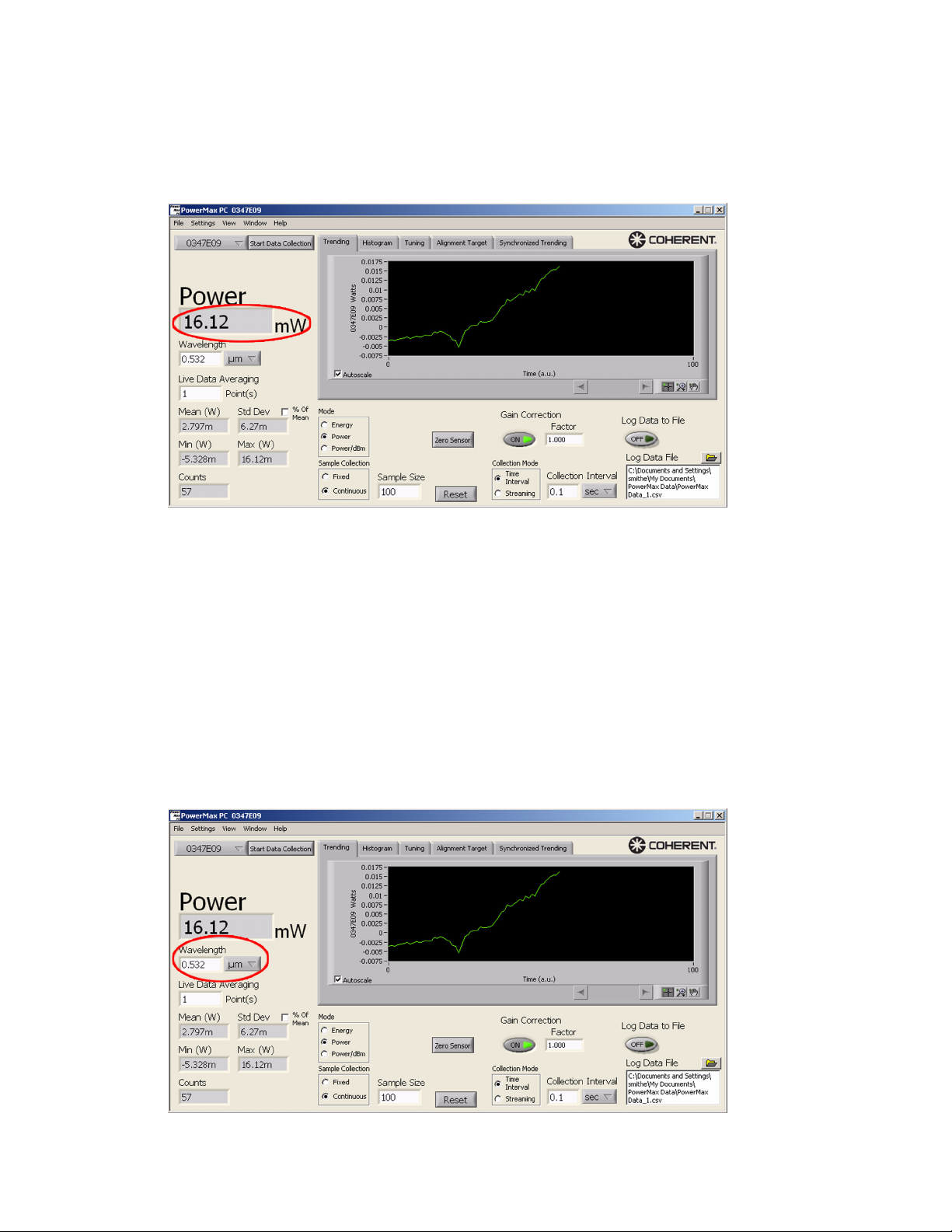
Live Reading Displays the current sensor reading, if Live Data Averaging is set to
1 point. If Live Data Averaging is set to n points, the Reading indicator displays the average of the last n points.
Wavelength The Wavelength field is used to configure the sensor to automati-
cally account for spectral responsivity differences between the laser
wavelength and the calibration wavelength. Use this field to enter
your laser wavelength.
• µm is the unit default but can be changed to nm by clicking the
units dropdown menu (next to the wavelength) and selecting
nm.
• If a wavelength outside the allowable range is requested, the
nearest minimum value or maximum value will be entered and
displayed.
30
Page 41

Operation
Live Data Averaging Enables averaging of the last n data points for the power/energy and
plot displays. This is computed as a moving average.
n can be set from 0-to-60 seconds and 2-to-1000 pulses, depending
upon the mode of operation.
Notes:
• Live data averaging is always in points, with 10 points per
second in Power mode, and arbitrary points per second in
Pulsed Joules mode.
• With optical sensors, live data averaging is always in Power
mode with 10 points per second.
Mean Displays the mean of the last n Sample Size samples. The value
updates as new samples are acquired. A sample size of 100 will
display the stats on two samples, then three, and continue to the n
sample. If the software is in Continuous mode, the statistics will
continue to update, using the last n samples. In Fixed mode, the
statistics will hold after the n
th
sample.
th
31
Page 42
PowerMax-USB/RS User Manual
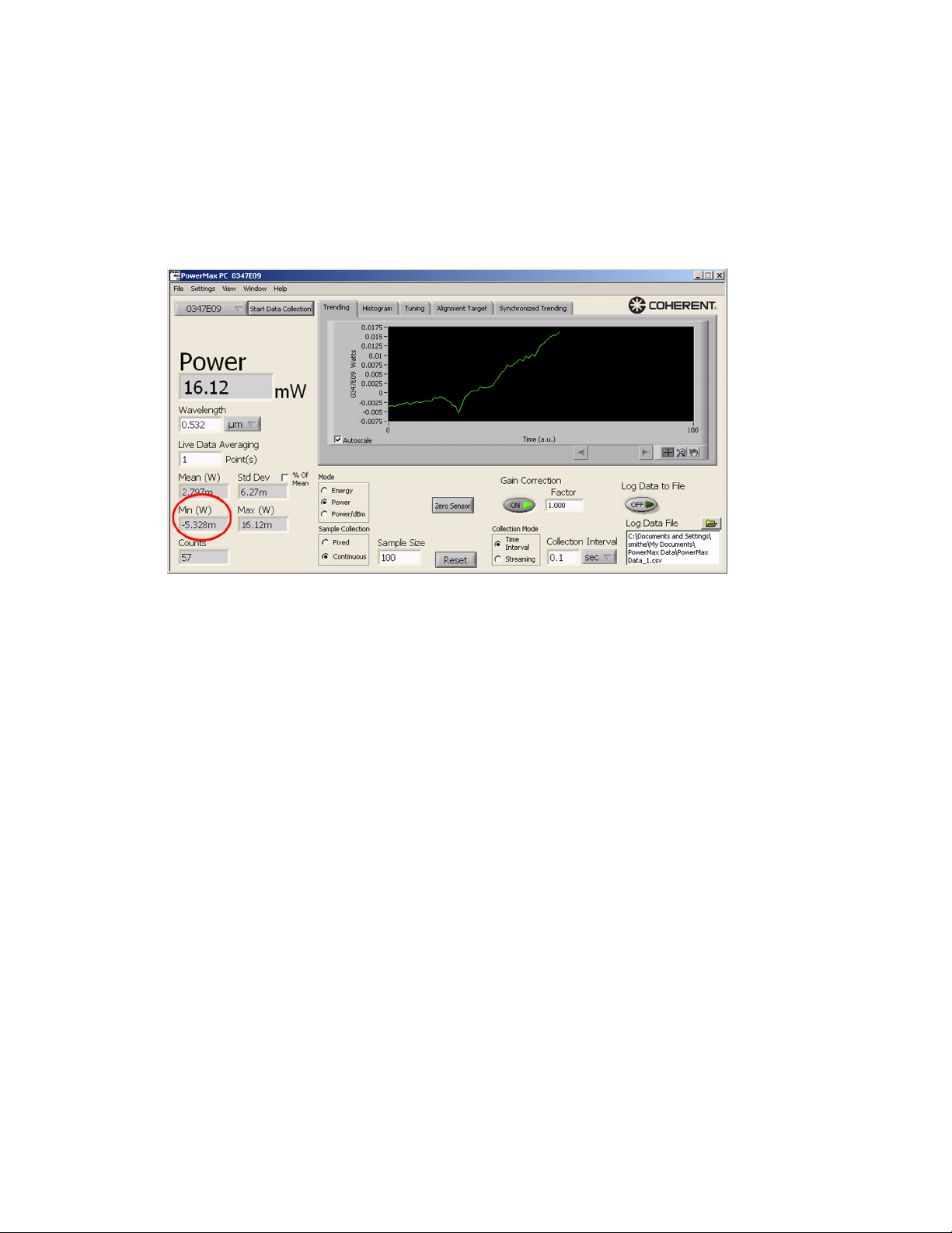
Min Displays the minimum value in the last n Sample Size samples. The
value updates as new samples are acquired. Example: A sample size
of 100 will display the stats on two samples, then three samples, and
continue to the nth sample. If the software is in Continuous mode, the
statistics will continue to update, using the last n samples. In Fixed
th
mode, the statistics will hold after the n
sample.
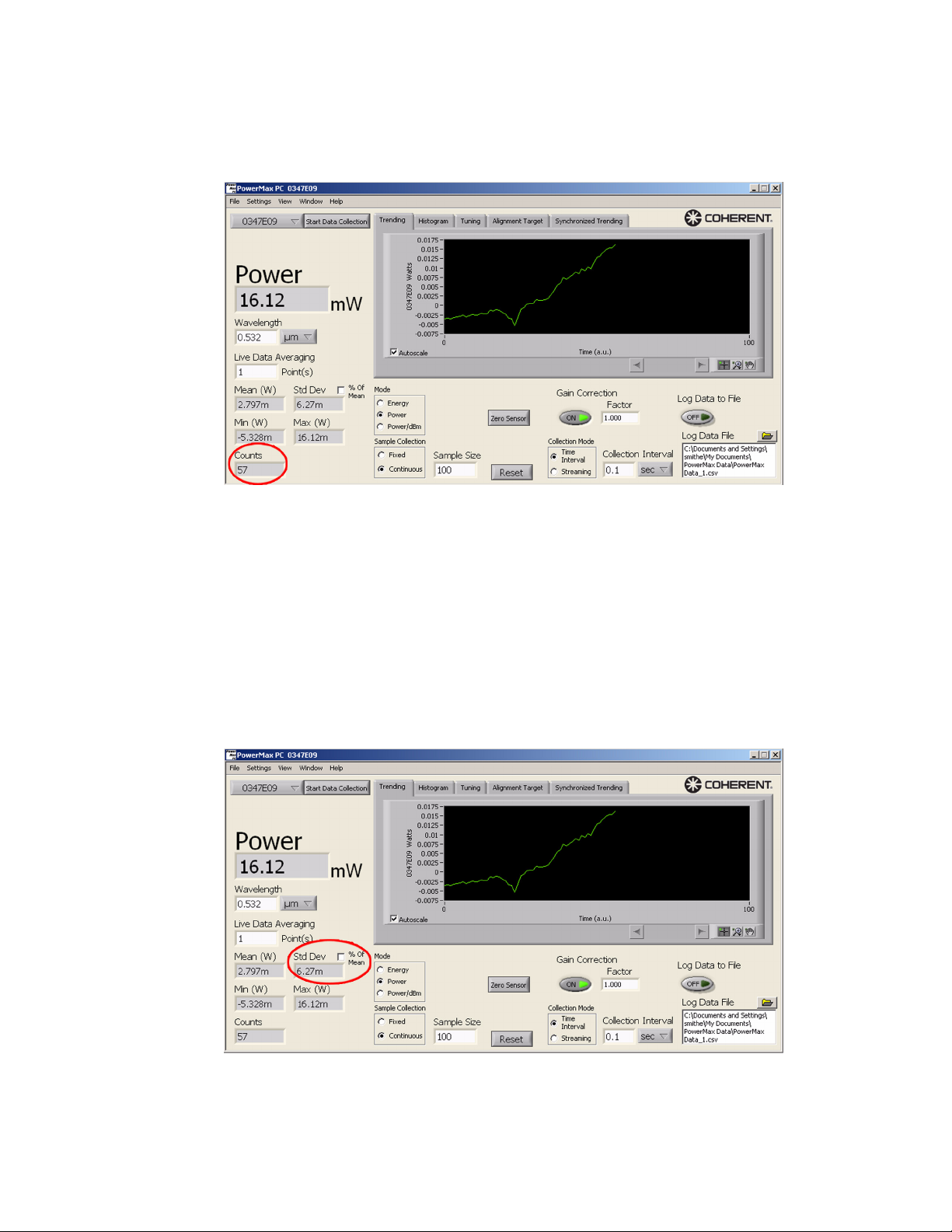
Counts Displays the number of measurements taken in the current data set.
Pressing the Reset button resets the counter.
• In Fixed Sample Collection mode, the Counts field increments
until the batch contains the number of samples entered in the
Sample Size field. At this point, the statistics and the Trending
chart will stop updating.
• In Continuous Sample Collection mode, the Counts field
continues incrementing indefinitely as more samples are
collected in the batch and plotted in the Trending chart. Even
though the Counts field continues to increment, the statistics
parameters themselves are calculated from the last n number of
samples, and the Trending chart displays the last n number of
32
Page 43
Operation
samples, where n is the number of samples entered in the
Sample Size field.
Std Dev Displays the Standard Deviation of the last n Sample Size samples.
The value updates as new samples are acquired. Example: A sample
size of 100 will display the stats on two samples, then three samples,
and continue to the nth sample.
• If the software is in Continuous mode, the statistics will
continue to update, using the last n samples.
• In Fixed mode, the statistics will hold after the n
th
sample.
33
Page 44
PowerMax-USB/RS User Manual
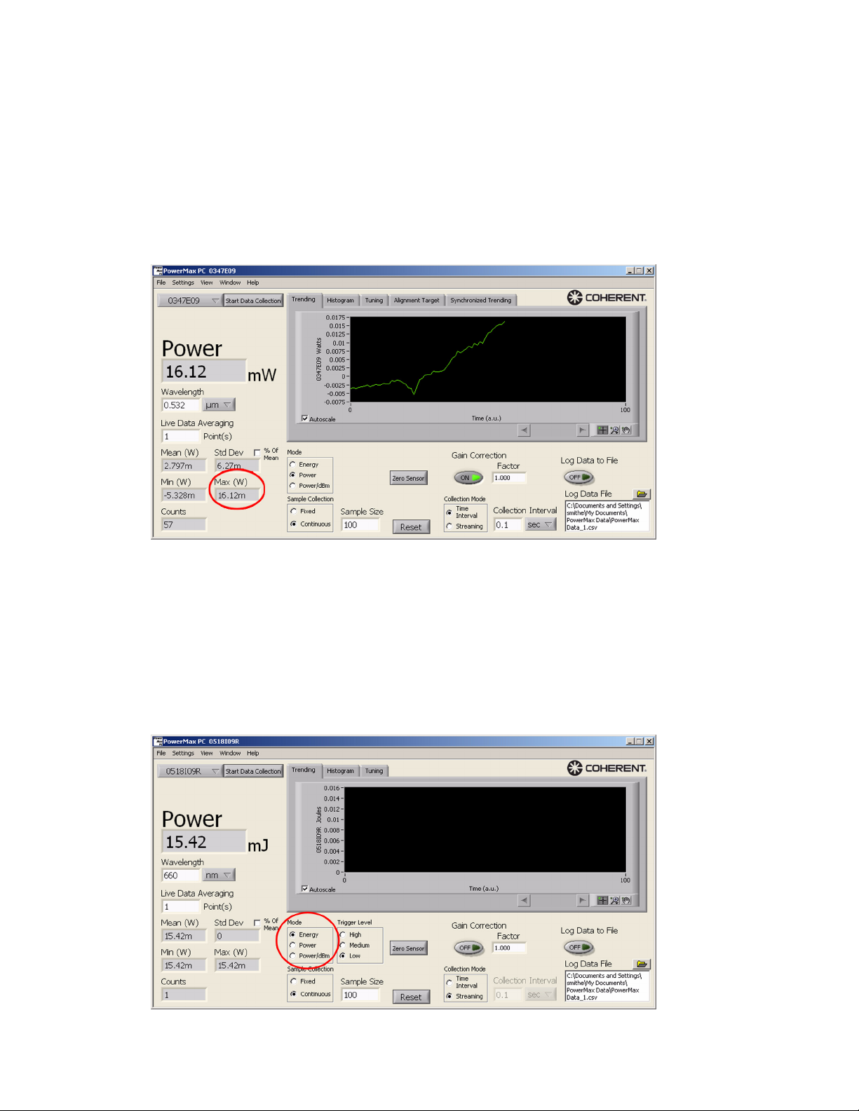
Max Displays the maximum value in the last n Sample Size samples. The
value updates as new samples are acquired. Example: A sample size
of 100 will display the stats on two samples, then three samples, and
continue to the nth sample.
• If the software is in Continuous mode, the statistics will
continue to update, using the last n samples.
• In Fixed mode, the statistics will hold after the n
th
sample.
Mode Selects the measurement mode: Energy (J), Power (W), or
Power/dBm.
Energy refers to a special “long-pulse joules” mode using a thermopile sensor in which the energy in a single long-pulse greater than
1 msec can be integrated by the thermopile sensor to calculate and
display the energy in the pulse.
34
Page 45
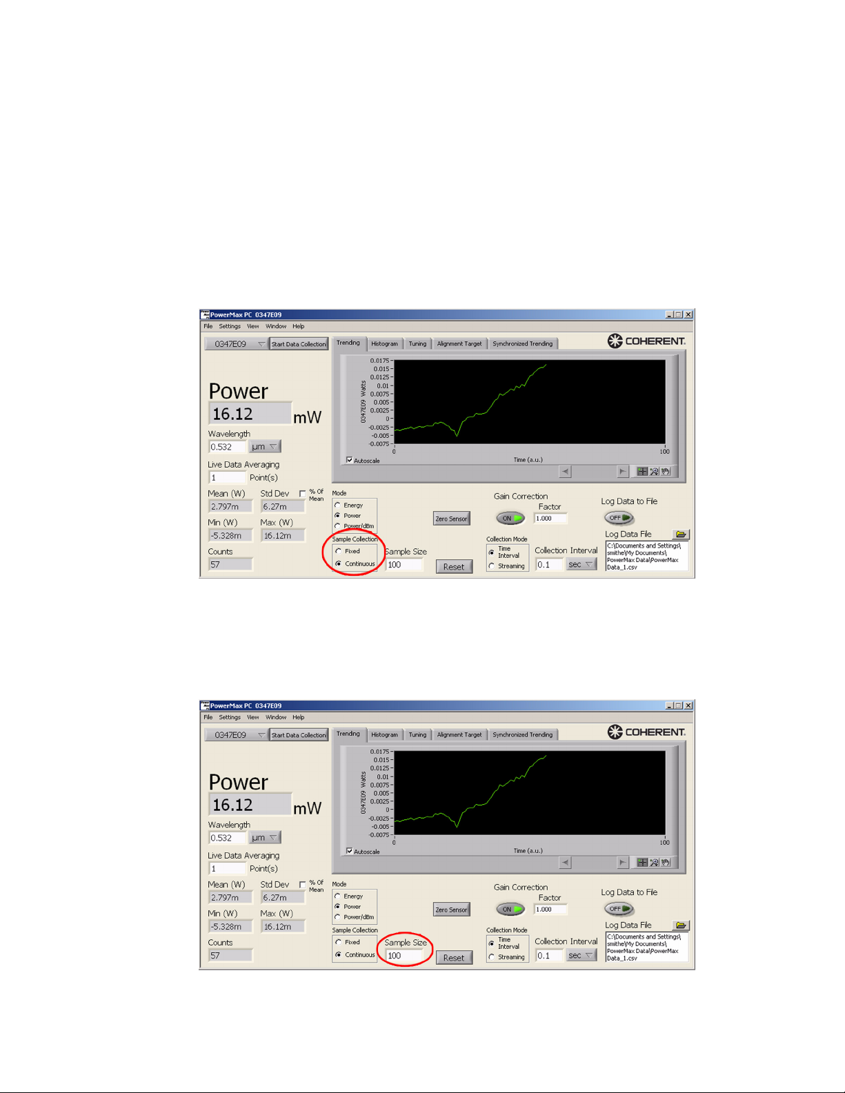
Sample Collection Selects the logging/plotting mode:
• Fixed takes and plots the number of data points shown in the
Sample Size and holds the results after the nth sample.
• Continuous takes continuous data and plots the number of data
points shown in the Sample Size in the chart window. The
newest data continually scrolls in the window.
• The default sample rate for all PowerMax-USB and
PowerMax-RS sensors is 10 samples per second. To use a
different sample rate, change the Collection Interval.
Operation
Sample Size Selects the sample size to collect when in Fixed mode, and the
sample size to use for statistics when in either Fixed or Continuous
mode.
35
Page 46

PowerMax-USB/RS User Manual
Zero Sensor Zeroes the PowerMax sensor.
Reset Button Clicking the Reset button:
• Resets the data set used for statistics (Mean, Min, Max, and Std
Dev).
• Resets Counts to 1.
• Clears Trending and other charts.
36
Page 47
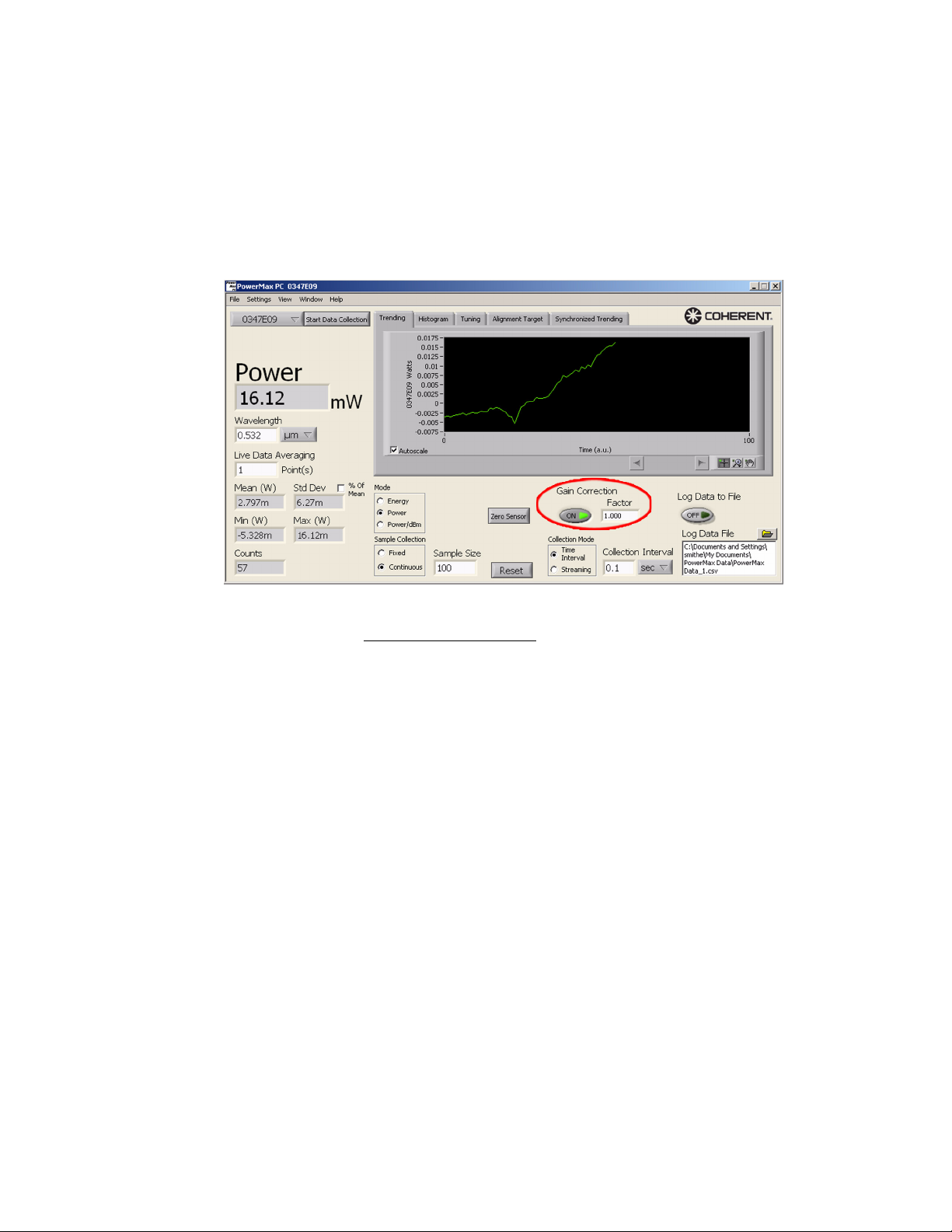
Gain Correction Enables/disables Gain Correction.
• Default value: Off
• Range: On (True), Off (False)
• When Gain Correction is enabled, measurements taken by the
sensor will be multiplied by the Gain Factor.
Operation
Gain Correction Factor
Sets the gain correction factor stored in the PowerMax sensor.
• Default Value: 1.0
• Range: 0.001 to 100000.0
The Gain Correction Factor control indicates the current gain correction factor stored in the PowerMax sensor. To change this setting,
enter the desired factor into the Gain Correction Factor control. This
factor is not applied unless Gain Correction is enabled.
37
Page 48
PowerMax-USB/RS User Manual
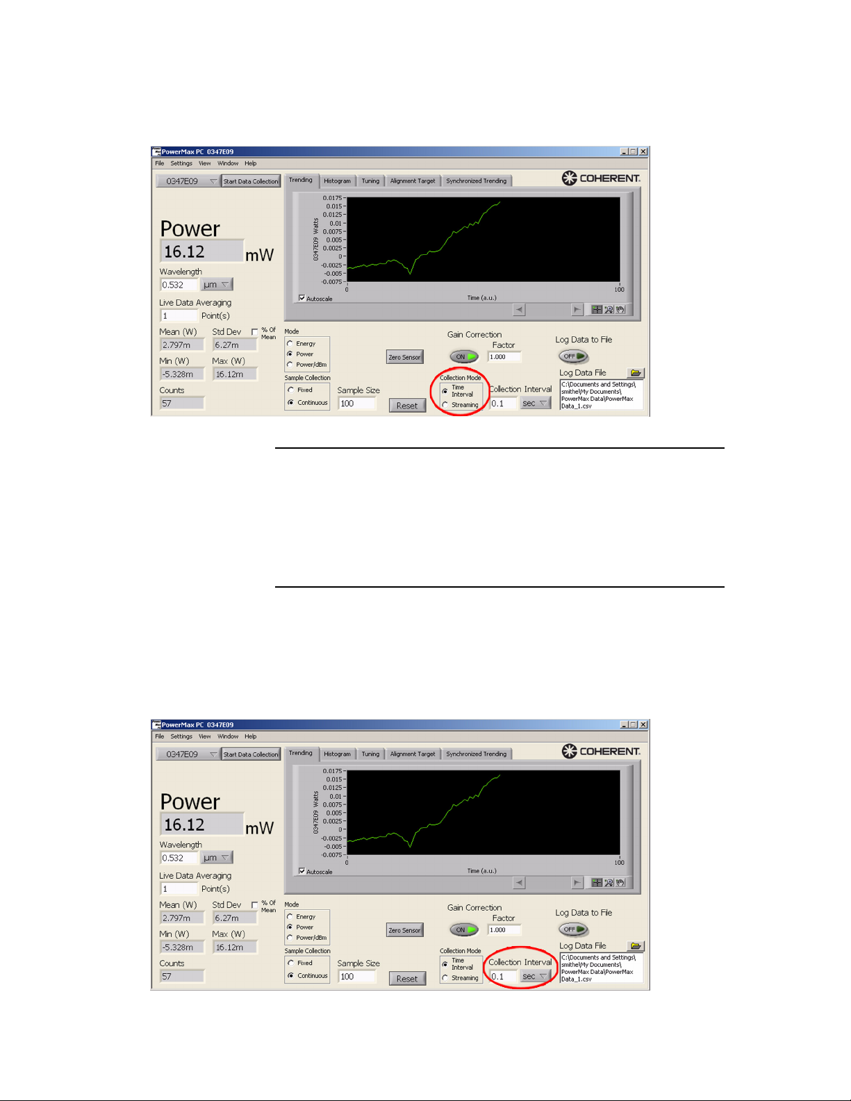
Collection Mode Selects between continuous data acquisition and data acquisition on
a fixed-time interval.
Changing between Time Interval and Streaming collection
modes during data collection automatically clears the data plot
display and the statistics batch. Clearing the plot display and
statistics batch is done to prevent mixing of data sets with two
different time bases. When set to Streaming, the collection
interval is automatically set to 0.1 seconds.
Collection Interval Sets the collection interval (seconds, minutes, or hours) when
Collection Mode is set to Time Interval. This control is grayed-out
when Collection Mode is set to Streaming.
38
Page 49
Operation
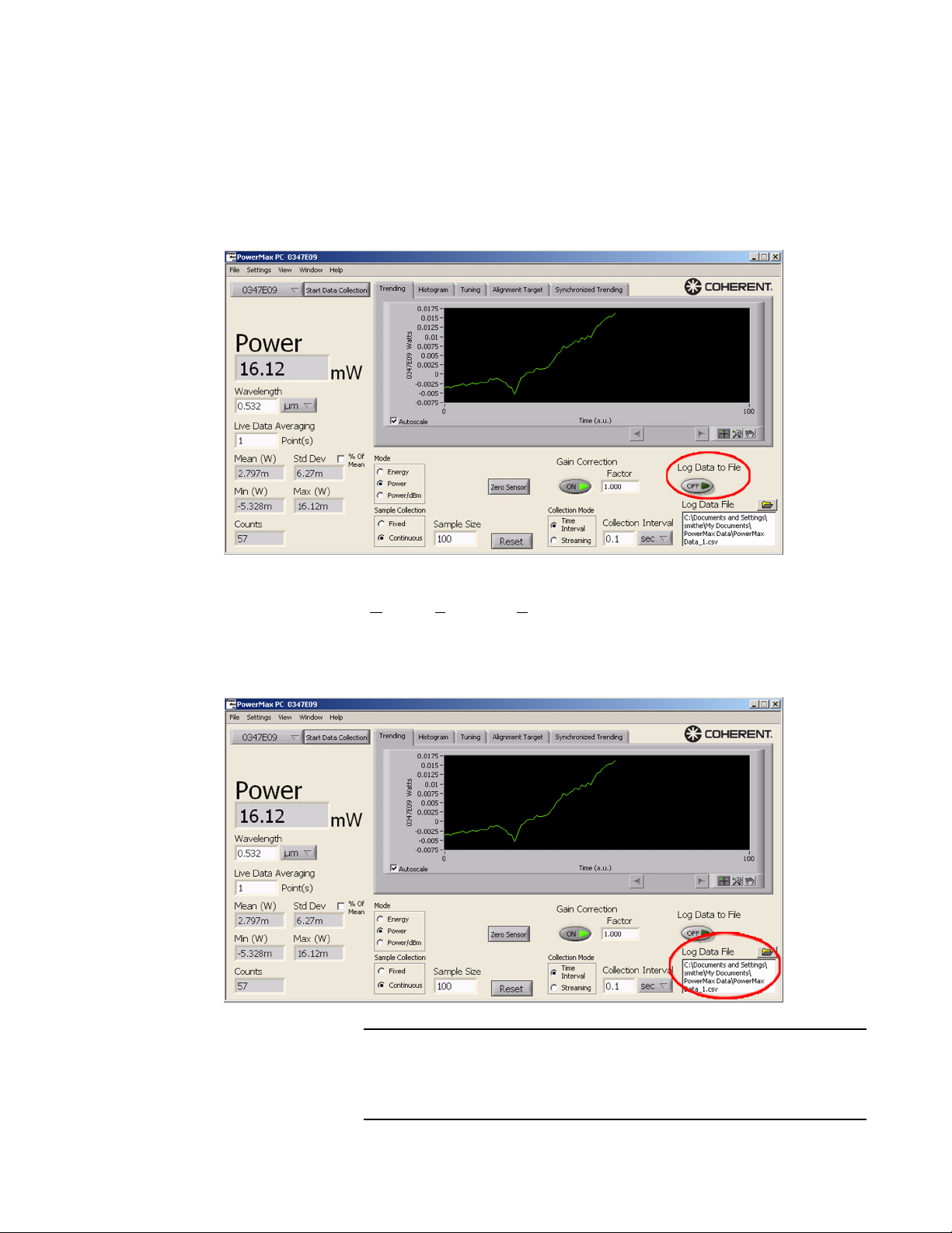
Log Data to File Enables/disables saving currently-acquired data to the Log Data file:
• If the Collection mode is Time Interval, data is logged to the
Log Data file at the interval specified under Collection
Interval.
• If the Collection mode is Streaming, all data is logged to the
Log Data file.
Log Data File Lists the file currently used to log data. The file is saved in “csv”
(Comma-Separated Values) format, which you can automatically
open in Excel by double-clicking on the file name. To view a previously-saved data file, select View Saved Data File from the File
menu.
Each time you toggle the Log Data to File button, the number
appended to the file name is automatically incremented - this
prevents the accidental overwriting of data.
39
Page 50
PowerMax-USB/RS User Manual
Menus
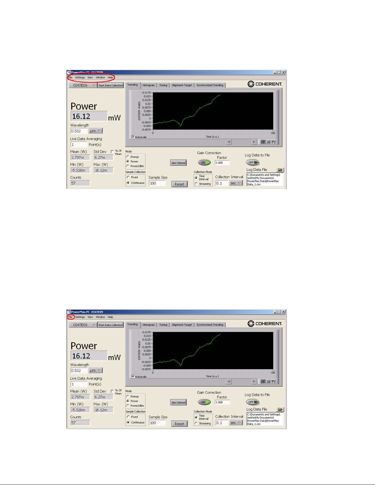
File Menu Options available under the File menu:
Five drop-down menus appear on the PowerMax PC Front panel:
File, Settings, View, Window, and Help. This section discusses each
of those menus.
Figure 6. Drop-Down Menus
• Viewing a previously-saved data file (shortcut: <Ctrl>+<V>)
(page 41)
• Opening a new Front panel (shortcut: <Ctrl>+<N>)
(page 42)
• Printing the current window (shortcut: <Ctrl>+<P>)
(page 43)
• Printing the current graph or chart (page 44)
• Exiting the program (shortcut: <Ctrl>+<Q>) (page 44)
Figure 7. File Menu
40
Page 51
Operation
View Saved Data File
To view information previously saved in a data file:
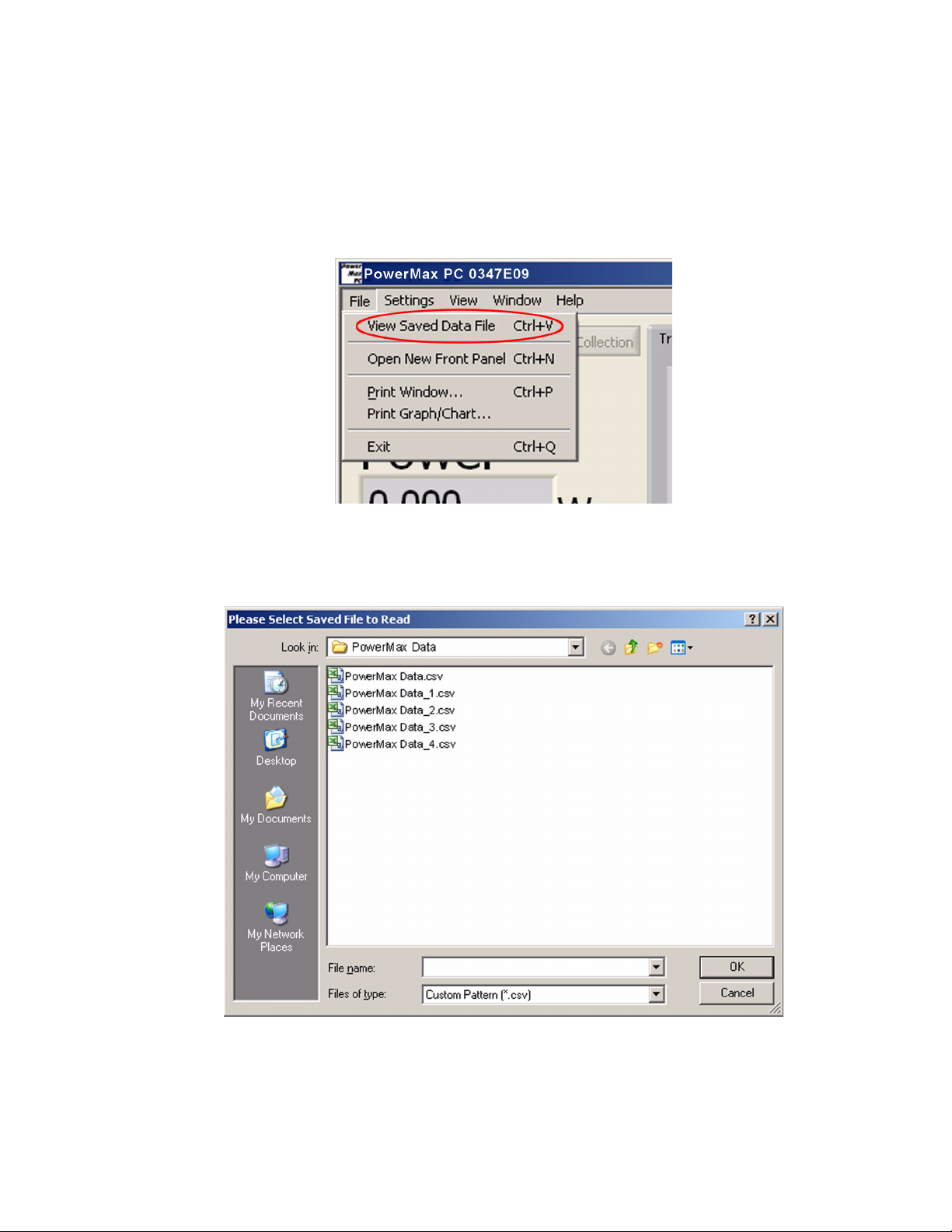
1. Click View Saved Data File (shortcut: <Ctrl>+<V>) from the
File dropdown menu:
A menu similar to the following will display:
41
Page 52

PowerMax-USB/RS User Manual
2. Select the name of the file you want to view and then click OK
to display a chart that contains all the saved data. Here is an
example chart:
Open New Front Panel
The purpose of opening a new Front panel is to control, monitor, and
simultaneously log data—from multiple sensors—to separate files.
This is useful for burn-in stations, where it is necessary to collect
data from several lasers at the same time by running several
PowerMax sensors on one PC.
A sensor cannot be active in more than one Front panel at a time.
To open a new panel, click Open New Front Panel (shortcut:
<Ctrl>+<N>) from the File dropdown menu:
42
Page 53
Operation
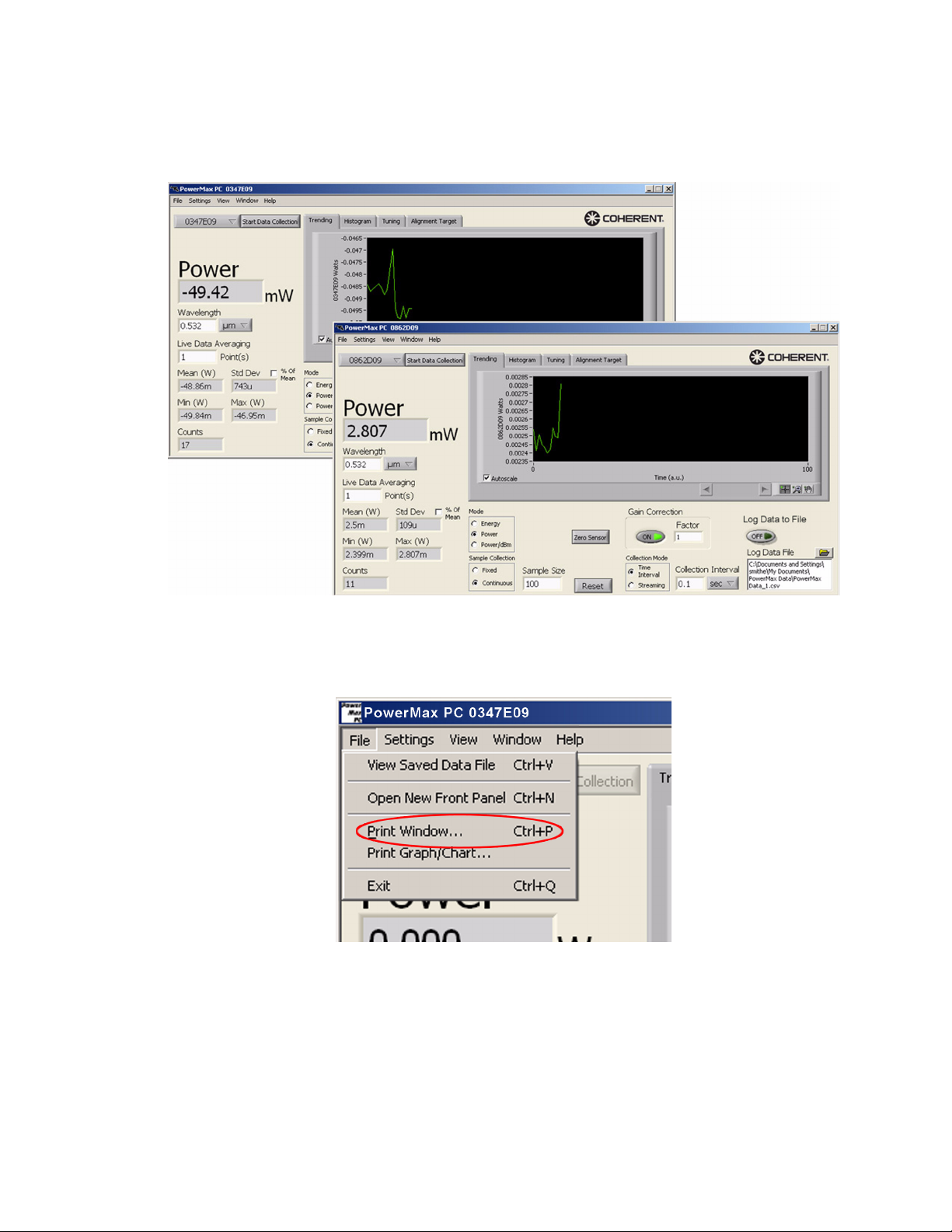
Here is an example of data from two sensors, each displayed within
its own Front panel:
Print Window
Selecting Print Window (shortcut: <Ctrl>+<P>) from the File drop-
down menu prints the entire active window—including graphs and
charts—exactly as it appears on the screen.
43
Page 54

PowerMax-USB/RS User Manual
Print Graph/Chart
Like the Print Window option, selecting Print Graph/Chart on the
File dropdown menu prints the entire active window; however, this
option uses inverted colors to print graphs and charts.
Exit
Selecting the Exit option (shortcut: <Ctrl>+<Q>) on the File dropdown menu closes the PowerMax PC program.
44
Page 55
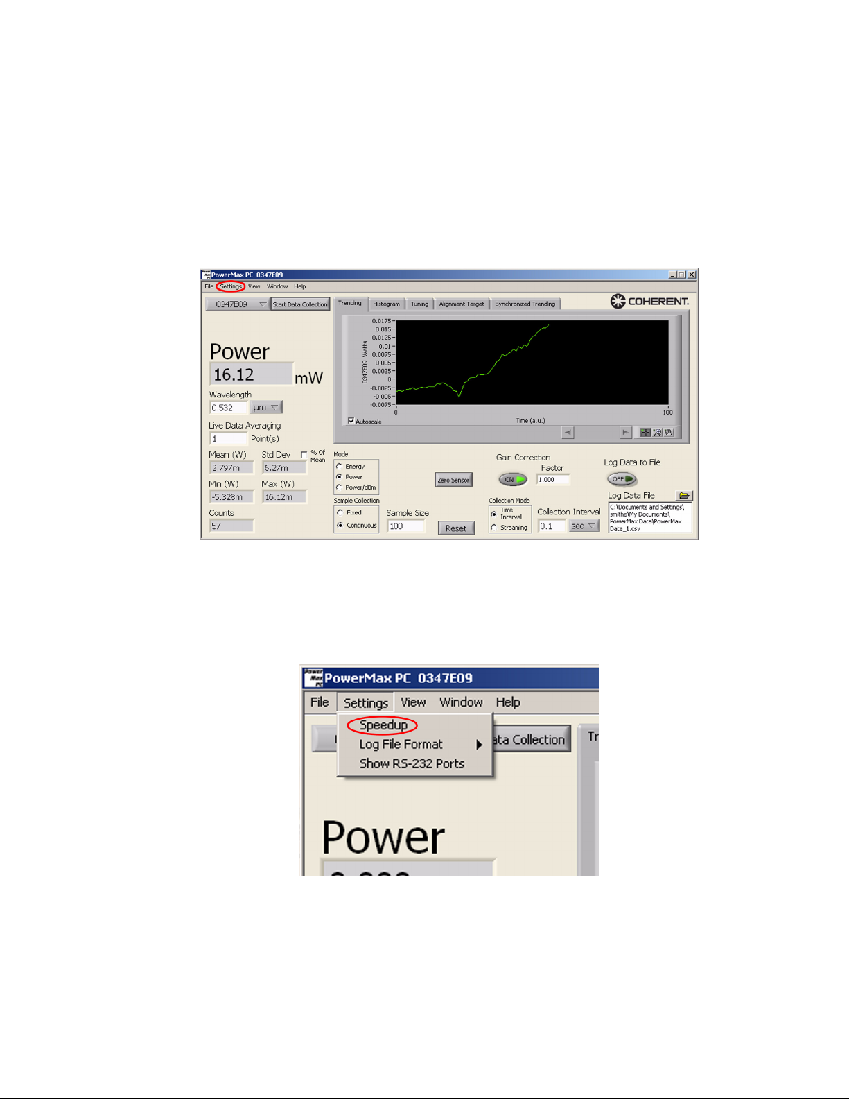
Settings Menu Options available under the Settings menu:
• Turning Speedup on or off (page 45)
• Choosing the log file format (refer to “Log Data File” on
page 39 and “Log Data to File” on page 39 for general information about saving data)
• Showing RS-232 ports (page 46)
Operation
Figure 8. Settings Menu
Speedup
Selecting or de-selecting Speedup on the Settings dropdown menu
controls the host data.
45
Page 56

PowerMax-USB/RS User Manual
Due to the natural thermal response of thermopile sensors, they have
a relatively slow response speed. To make faster measurements with
these sensors, use a speedup algorithm while taking power measurements. The Speedup option allows you to turn this algorithm on or
off for various functions. The trade off to using Speedup is some loss
of accuracy.
Log File Format
Selecting Log File Format from the Settings dropdown menu allows
the following options to be added or removed from the log file:
• Sensor data
• Calculated (ratio) data
• Position-Sensing Thermopiles: X Position, Y Position
• (thermopile quad sensors only) X and Y positions
Show RS-232 Ports
46
Page 57

View Menu
Operation
Enabling this option will list available RS-232 ports on the Select
Sensor dropdown list. To select the RS-232 port, click on the appropriate COM number in the dropdown list. Here is an example:
Figure 9. View Menu
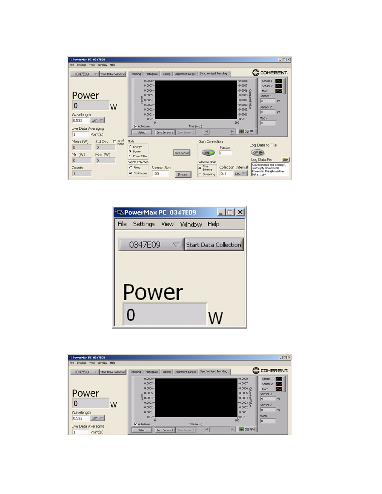
Use this menu to select which portion of the display is visible: Full
Application, Power/Energy, or Power/Energy and Plot.
47
Page 58
PowerMax-USB/RS User Manual
• Example of a Full Application (shortcut: <Ctrl>+<F>) view:
• Example of a Power/Energy data view:
• Example of a Power/Energy and Plot view:
48
Page 59

Window Menu
Operation
Figure 10. Window Menu
When more than one window is open—that is, when there is more
than one sensor connected to the computer and each sensor has its
own Front panel open—this menu item allows you to determine the
relative position of the open Front panels on the monitor screen.
Options available under the Window menu are:
Help Menu
• Tile Windows: Displays open Front panels edge-to-edge.
If five or more Front panels are open, only the first four panels
will tile—the rest of the open panels will stay in their current
location.
• Cascade Windows: Displays all open Front panels, stacked and
cascading from the upper left to the lower right of the screen.
Figure 11. Help Menu
49
Page 60
PowerMax-USB/RS User Manual
Options available under the Help menu:
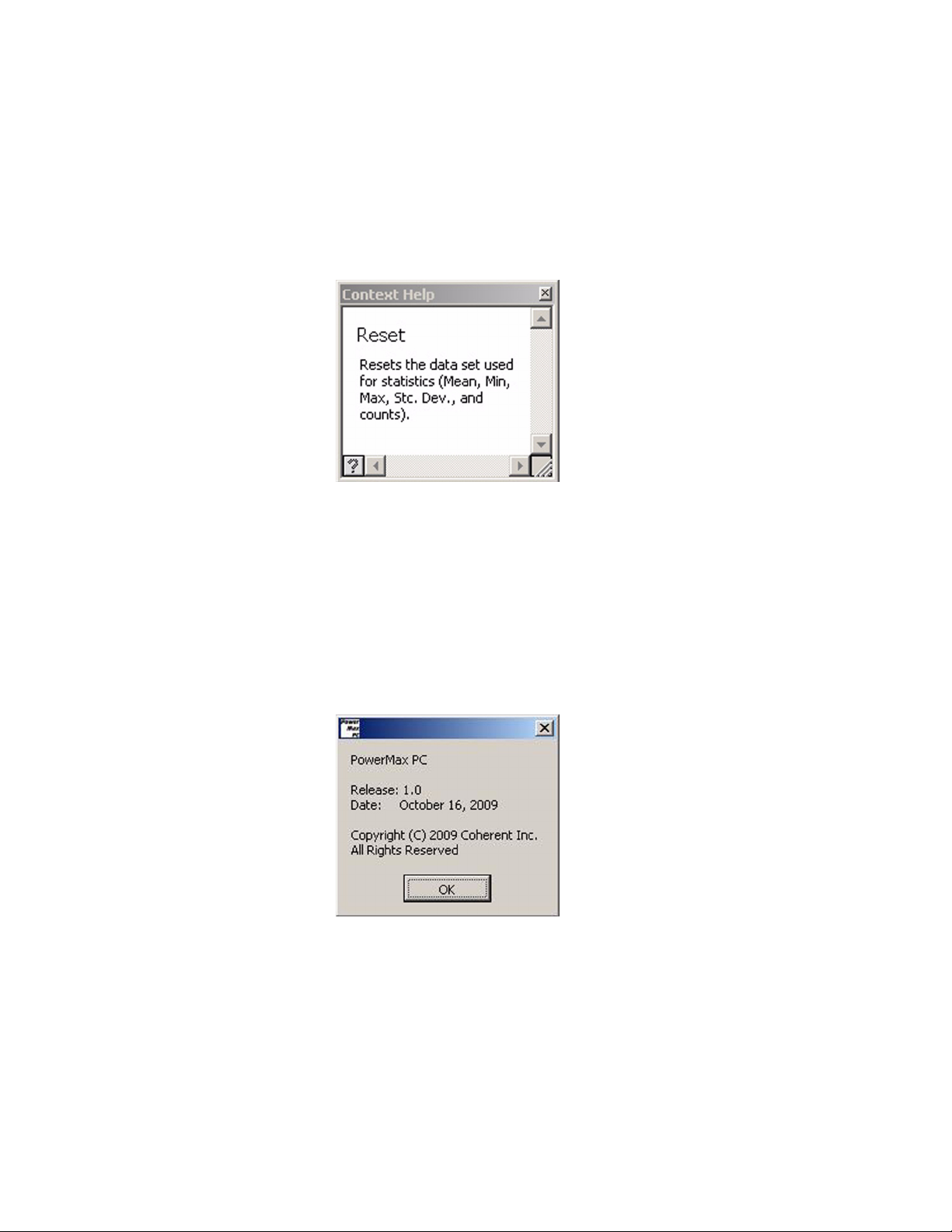
• Show Context Help: Opens a separate window that displays
information about the screen item currently beneath the mouse
cursor (shortcut: <Ctrl>+<H>). For example, a screen similar
to the following will appear if you select Show Context Help
and then hover the cursor over the Reset button:
To turn this feature off, either de-select it from the Help dropdown menu, or click the “X” in the top right-hand corner of the
Context Help screen.
• PowerMax PC Help: Displays this Help file
• About PowerMax PC: Displays version and copyright infor-
mation for the PowerMax PC software. For example:
50
Page 61

Host Interface
HOST INTERFACE
In this section:
• Introduction (this page)
• Message terminators (page 52)
• Host command quick reference (page 53)
• SCPI interface section (page 55)
• Legacy LaserPAD/SSIM interface section (page 65)
• Data streaming transmission interface section (page 70)
• Operational parameters (page 71)
Introduction
For those customers who want to communicate with Coherent
PowerMax-USB and PowerMax-RS sensors over a host interface—instead of using our PowerMax PC software—we are
providing a complete remote host command interface that can be
used to control all aspects of sensor operation. You can use this host
interface environment to communicate with these sensors in an ad
hoc manner using a terminal emulator, or to write custom software
in a number of programming environments, including Visual Studio
and LabVIEW.
The PowerMax-USB sensors utilize a standard Windows COM class
driver and operate much like a serial port. After the driver is
installed, the sensor will show up as a device on the computer's
COM port and the host interface will accept commands and respond
in ASCII format using commands that adhere to the SCPI standard.
The sensors also support a second ASCII command set used by our
legacy LaserPAD/SSIM products, which allow drop-in software
compatibility. For new software installations, we recommend using
the newer SCPI-based command set.
For customers who prefer to capture streaming data over the host
port—instead of the query method—we have implemented a special
data streaming command interface. This interface requires the user
to monitor for a high/low bit (as described under “Data Streaming
Transmission Interface Section” on page 70), and is a more
advanced interface than the standard SCPI ASCII command
language. For customers who want streaming, and who want to
51
Page 62

PowerMax-USB/RS User Manual
stream in a purely ASCII format, there is a command in the legacy
LaserPAD/SSIM command set that can be used (refer to “Legacy
LaserPAD/SSIM Interface Section” on page 65).
The PowerMax-RS sensors support the same command set as the
PowerMax-USB sensors. No driver is required, as they function as
a serial device on an RS-232 port.
For customers who prefer to program in the National Instruments
LabVIEW environment, we provide a full set of LabVIEW drivers
on the installation CD that shipped with your system. In addition to
a basic Getting Started VI that will show you how to initiate communication with a PowerMax-USB or PowerMax-RS sensor, we also
provide access to the architecture of our PowerMax PC software,
which was written using our LabVIEW driver library.
Message Terminators
Messages Received by the Sensor
Messages between the sensor and the host computer are comprised
entirely of ASCII string characters, and all message strings passing
through the host interface are terminated to signal the end of a
message string.
The one exception to messages comprised entirely of ASCII string
characters is the Data Streaming Transmission Interface. After data
streaming is initiated, the host sends unsolicited streaming data in
non-ASCII format in which a high bit is set on all transmissions. The
streaming data mode is covered under “Start Data Streaming
Command” and “Stop Data Streaming Command,” beginning on
page 68.
Messages received by the sensor must be terminated by a carriage
return (decimal 13). Line feed characters (decimal 10) are discarded
so message terminator flexibility can be attained. A command or
query is considered incomplete without the terminator. The
maximum length of any message received by the sensor is 200 bytes.
Messages Sent by the Sensor
All legacy SSIM messages sent by the sensor (defined under
“Legacy LaserPAD/SSIM Interface Section” on page 65) are terminated by a carriage return.
All other messages sent by the sensor (defined under “SCPI Interface Section” on page 55 and “Data Streaming Transmission Interface Section” on page 70) are terminated by a carriage return and
line feed pair.
52
Page 63

Host Interface
Host Command
Quick
The following table gives a brief description of all host commands.
For detailed information about a specific command, go to the page
referenced in the right-hand column.
Reference
Table 5. Host Command Quick Reference (Sheet 1 of 2)
Command Description Page #
SCPI INTERFACE
SCPI Common Commands
*RST Resets all operational parameters to their power-on states. 56
*IDN? Queries the sensor identification string. 56
System Options
SYSTem:STATus? Queries the system status. 56
SYSTem:INFormation:TEMPerature? Queries the sensor temperature. 57
SYSTem:SYNC Resets the system measurement sync timer. 57
SYSTem:SYNC? Queries the system measurement sync timer. 57
SYSTem:COMMunicate:HANDshaking Selects the state of SCPI message round trip handshaking. 57
SYSTem:COMMunicate:HANDshaking? Queries the state of SCPI message round trip handshaking. 57
Error Record Reporting and Collection
SYSTem:ERRor:COUNt? Queries the number of error records in the error queue at the
time of the query.
SYSTem:ERRor:NEXT? Queries the next error record(s) in the error queue. 59
SYSTem:ERRor:ALL? Queries all error records in the error queue at the time of the
query.
SYSTem:ERRor:CLEar Clears all error records in the error queue. 60
Measurement Setup and Control
CONFigure:MEASure Sets the sensor measurement mode. 60
CONFigure:MEASure? Queries the sensor measurement mode. 60
CONFigure:SPEedup Sets the speedup state. 60
CONFigure:SPEedup? Queries the speedup state. 60
CONFigure:WAVElength Sets the current wavelength. 60
CONFigure:WAVElength? Queries the current wavelength. 60
CONFigure:GAIN:COMPensation Enables or disables gain compensation. 61
CONFigure:GAIN:COMPensation? Queries the state of gain compensation. 61
CONFigure:GAIN:FACTor Sets the gain compensation factor. 61
CONFigure:GAIN:FACTor? Queries the gain compensation factor. 61
CONFigure:ZERO Sets the current measurement as the zero baseline measurement. 61
TRIGger:PTJ:LEVel Selects the pulsed thermopile Joules mode trigger sensitivity
level.
TRIGger:PTJ:LEVel? Queries the pulsed thermopile Joules mode trigger sensitivity
level.
Measurement Reading
READ? Queries the last recorded measurement at the time of the query. 62
Sensor Information
59
59
62
62
53
Page 64

PowerMax-USB/RS User Manual
Table 5. Host Command Quick Reference (Sheet 2 of 2)
SYSTem:INFormation:SNUMber? Queries the serial number. 63
SYSTem:INFormation:CDATe? Queries the calibration date. 63
SYSTem:INFormation:MDATe? Queries the manufacturing date. 63
SYSTem:INFormation:TYPE? Queries the sensor type and connection configuration. 64
SYSTem:INFormation:DIAMeter? Queries the aperture diameter. 64
SYSTem:INFormation:WAVElength? Queries the default wavelength. 64
LEGACY LASERPAD/S S I M INTERFACE
h Queries the list of LaserPAD/SSIM commands. 65
*rst Resets all operational parameters to their power-on states. 65
*ind Queries the hardware description. 66
v? Queries the firmware version. 66
vp? Queries the data stream protocol version. 66
msn? Queries the serial number. 66
mcal? Queries the calibration date. 66
mfg Queries the manufacturing date. 66
df? Queries the sensor family. 66
app Queries the aperture diameter. 67
rmi Queries the minimum range. 67
rmx Queries the maximum range. 67
spd? Queries the speedup state. 67
spd Toggles the speedup state. 67
wl? Queries the default wavelength. 67
wv? Queries the current wavelength. 67
wv Sets the current wavelength. 68
pw? Queries the current power reading. 68
pos Queries the current beam position. 68
tmp Queries the current thermistor ADC value. 68
dst Enables LaserPAD/SSIM interface data streaming. 68
dsp Disables LaserPAD/SSIM interface data streaming. 69
DATA STREAMING TRANSMISSION INTERFACE
INITiate Enables data streaming interface transmission. 70
ABORt Disables data streaming interface transmission. 70
54
Page 65

SCPI Interface Section
Host Interface
Syntax and Notation Conventions
Unless otherwise specified, all SCPI commands and queries follow
the syntax and notation conventions specified by the SCPI Standard.
For more information, refer to the SCPI Standard—found on the IVI
Foundation website.
The base-10 numeric data format specification is used heavily in this
document. Unless otherwise specified, numeric data items are represented as:
• integer values
• non-scientific notation floating point values
• scientific notation floating point values (upper or lower case E)
For example, the following data values are functionally equivalent:
• 31256
• 31256.0
• 3.1256E4
• 31.256E3
• +3.1256E+4.
Unless otherwise specified, non-numeric data items (typically
referred to as strings) are not quoted.
Enumerated values must exactly match, using the long form/short
form comparison rules defined under the SCPI Standard.
55
Page 66

PowerMax-USB/RS User Manual
Commands and Queries
SCPI Common Commands
The SCPI Standard specifies a standard set of common commands.
All common commands and queries start with an asterisk.
Reset Command - *RST
Resets all operational parameters to their power-on states. Reset
does not affect factory settings. Also see “Reset Command - *RST”
on page 56.
Command: *RST
Query: none
Identification Query - *IDN?
Queries the sensor identification string, such as model name, firmware version, and firmware date.
Query: *IDN?
Reply: “Coherent, Inc – PowerMax” + <type> + “–” + <version> +
“–” + <firmware date> Note: The quotes are not transmitted.
Example reply: Coherent, Inc – PowerMax-USB – V1.3 – Jul 10
2009
System Options The system commands and queries access functionality that is
exclusive of sensor measurement functions. These commands can
be sent at any time without affecting a measurement in progress.
System Status
Queries the system status. Status is returned in a string containing
one ASCII character for each status condition that is asserted. If the
status condition character is present, the condition is asserted. If the
status condition character is absent, the condition is not asserted.
The following table describes the status condition character
mapping.
Table 6. Status Condition Character Definitions
STATUS CHARACTER STATUS CONDITION
T Damage temperature is exceeded
0 (zero) No status condition is asserted
56
Page 67

Host Interface
Command: none
Query: SYSTem:STATus?
Reply: <status>
Example: If the sensor damage temperature is exceeded, the system
status query will return:
“T” Note: The quotes are not transmitted.
Sensor Temperature
Queries the sensor temperature.
Command: none
Query: SYSTem:INFormation:TEMPerature?
Reply: <sensor temperature in degrees Celsius in integer format>
The literal string “NA” (quotes not included) is returned if the sensor
does not have a temperature measurement capability.
System Sync
Resets the system measurement sync timer. This query gets the
system measurement sync timer value. The system measurement
sync timer is a free-running timer that increments by one for every
1 millisecond of elapsed time. It is necessary to synchronize the
measurement sync timers of all sensors that are used for applications
requiring synchronization. The maximum value of this timer is
4294967295 milliseconds; however, to counteract clock creep, the
system sync command should be sent at intervals not to exceed 10
minutes.
Command: SYSTem:SYNC
Query: SYSTem:SYNC?
Reply: <current timer value>
Message Handshaking
Selects the state of SCPI message round trip handshaking.
Command: SYSTem:COMMunicate:HANDshaking {ON|OFF}
Reply: OK if ON is selected; otherwise, no reply is sent
Default is OFF.
Query: SYSTem:COMMunicate:HANDshaking?
Reply: ON|OFF
If handshaking is ON:
• Empty commands (commands with only whitespace charac-
ters) reply with “OK\r\n”
57
Page 68
PowerMax-USB/RS User Manual
• Valid commands with valid data reply with “OK\r\n”
• Valid queries with valid data reply as explicitly defined else-
• Valid commands or queries which result in an error reply with
• Unrecognized commands or queries reply with “ERR100\r\n”
• Error queuing occurs, as explicitly defined elsewhere in this
If handshaking is OFF:
• All command and query response will behave as explicitly
where in this section, followed by “OK\r\n”
“ERR<n>\r\n”, where <n> is the error code number (see
“Error Record Reporting and Collection” on page 58).
document
defined elsewhere in this section
Error Record Reporting and Collection
Programming and system errors occasionally occur while testing or
debugging remote programs, and during measurement. Error strings
follow the SCPI Standard for error record definition:
<error code>,<quoted error string>
The host queries for errors in two steps:
1. The host queries for the number of error records available (N).
2. The host queries N times for the error records.
Errors are stacked up to 20 deep. In the case of error overflow, the
last error in the error list is an indication of error overflow.
The possible error strings are shown in the following table.
Table 7. Error Codes and Description Strings
ERROR CODE NUMBER QUOTED ERROR STRING ERROR DESCRIPTION
-350 “Queue overflow” Error queue is full
-310 “System error” Unexpected/unrecoverable hardware or software fault
0 “No error” No error
100 “Unrecognized command/query” The command or query is not recognized
101 “Invalid parameter” The command or query parameter is invalid
102 “Data error” A data error was encountered
58
Page 69

Host Interface
Error -350 is raised when the error queue becomes full. Non-“Queue
overflow” errors are replaced by “Queue overflow” errors when
there is exactly one available storage location available in the error
queue. No additional errors are added to the error queue if the error
queue is full.
Error -310 is raised when the firmware detects an unexpected or
unrecoverable error. This error condition includes unrecoverable
hardware faults.
Error 100 is raised when the sensor receives an unrecognized
command or query.
Error 101 is raised when the sensor receives a command or query
with one or more invalid data parameters.
Error 102 is raised when the sensor receives a command or query for
which no valid data exists.
Error Count Query
Queries the number of error records in the error queue at the time of
the query.
Command: none
Query: SYSTem:ERRor:COUNt?
Reply: <count of error records stored in integer format>
Error Query
Queries the next error record(s) in the error queue. More than one
error record may be queried using the optional <error record count>
parameter, which must be an integer value. A single error record is
returned if <error record count> is not specified. No reply is transmitted if no error records are available.
As the sensor transmits each error record:
• The error record is permanently removed from the error queue
• The queued error record count decrements by one
Command: none
Query: SYSTem:ERRor:NEXT? [<error record count>]
Default is not applicable.
Reply: <next available error record(s)>
All Error Query
Queries all error records in the error queue at the time of the query.
No reply is transmitted if there are no error records available.
59
Page 70

PowerMax-USB/RS User Manual
After completion of the reply transmission:
• The error queue will be empty
• The queued error record count will be zero
Command: none
Query: SYSTem:ERRor:ALL?
Reply: <all available error record(s)>
All Error Clear
Clears all error records in the error queue.
Command: SYSTem:ERRor:CLEar
Query: none
Measurement Setup and Control
Measurement Mode
Sets the sensor measurement mode to select either power (Watts) or
energy (Joules) measurement mode. Note: Joules measurement
mode is only possible with a thermopile type power sensor.
Command: CONFigure:MEASure {DEFault|J|W}
Default is W (Watts) mode.
Query: CONFigure:MEASure?
Reply: J|W
Error 100 is raised if the sensor is an optical sensor.
Speedup
Sets the speedup state. The query gets the speedup state.
Command: CONFigure:SPEedup {DEFault|ON|OFF}
Default is OFF
Query: CONFigure:SPEedup?
Reply: {ON|OFF}
Error 100 is raised if the sensor is an optical sensor.
Wavelength
Sets the current wavelength, which is committed to persistent
storage when it is changed. If the requested wavelength is greater
than the upper wavelength limit, the current wavelength is set to the
upper wavelength limit. Likewise, if the requested wavelength is
less than the lower wavelength limit, the current wavelength is set to
the lower wavelength limit. The minimum and maximum allowed
60
Page 71

Host Interface
wavelength may also be named as data arguments. The query gets
the current maximum or minimum allowed wavelengths, depending
on the optional query data argument.
Command: CONFigure:WAVElength {MINimum|
MAXimum|<requested wavelength in nm>}
Query: CONFigure:WAVElength? [MINimum|
MAXimum]
Reply (if [MINimum|MAXimum] is not specified):
<granted wavelength in nm>
Reply (if MAXimum is specified):
<allowed maximum wavelength in nm>
Reply (if MINimum is specified):
<allowed minimum wavelength in nm>
Gain Compensation
Enable/Disable State
Enables or disables gain compensation, which is committed to
persistent storage when it is changed. If gain compensation is
enabled, power readings sent over the host port will be measured
power multiplied by the gain compensation factor.
Command: CONFigure:GAIN:COMPensation {DEFault|OFF|ON}
Default is OFF
Query: CONFigure:GAIN:COMPensation?
Reply: OFF|ON
Factor
Sets the gain compensation factor, which is committed to persistent
storage when it is changed.
Command: CONFigure:GAIN:FACTor {DEFault|
<0.001..100000.0>}
Default is 1.0
Query: CONFigure:GAIN:FACTor?
Reply: <gain compensation factor>
Sensor Zero
Sets the current measurement as the zero baseline measurement. We
recommend that you zero the sensor prior to measuring power to null
out any offset in the power sensor. If you have recently touched a
thermopile or exposed it to heat, you must wait for the sensor to
settle back to a stable zero point before sending the Zero command.
Command: CONFigure:ZERO
61
Page 72

PowerMax-USB/RS User Manual
Pulsed Thermopile Joules Trigger Level
Selects the pulsed thermopile Joules mode trigger sensitivity level.
Command: TRIGger:PTJ:LEVel {DEFault|LOW|MEDium|HIGH}
Default is LOW
Query: TRIGger:PTJ:LEVel?
Reply: LOW|MEDIUM|HIGH
Querying Measurement Data
Queries the last recorded measurement at the time of the query. No
reply is transmitted if a measurement has not been recorded.
Command: none
Query: READ?
Reply: <last measurement record>
The last measurement record is composed of comma-delimited data
items generated at the same instant. The data items presented,
including a flags item, varies, depending on the sensor type as
enumerated in the following table.
Table 8. Measurement Data Record Formats
SENSOR TYPE MEASUREMENT MODE LAST MEASUREMENT RECORD FORMAT
Thermopile Mono
(PM-model thermopiles,
like PM-10)
Thermopile Quad
(LM-model thermopiles,
like LM-10)
Watts <power>,<flags>,<timestamp>
Joules <energy>,<flags>,<timestamp>
Watts <power>,<X position>,<Y position>,<flags>,<timestamp>
Joules <energy>,<flags>,<timestamp>
Optical Wat ts <power>,<flags>,<timestamp>
<power> will be expressed in Watts using the “%.5E” C formatting
specification.
<energy> will be expressed in Joules using the “%.5E” C formatting
specification.
<X position> and <Y position> will be expressed in mm using the
“%.2E” C formatting specification.
<timestamp> will be expressed in integer milliseconds. This timestamp is based upon the system sync function. Zero time is set when
the device receives the SYSTem:SYNC command.
The <flags> data item, which communicates qualification information, is reported with each data message. Qualification information—including various error conditions—is reported in a string
62
Page 73

containing one ASCII character for each qualification that is
asserted. If the qualification character is present, the qualification is
asserted. If the qualification condition character is absent, the qualification is not asserted. Each character present has a unique
meaning, as described in the following table.
Table 9. Flags Character Definitions
QUALIFICATION CHARACTER QUALIFICATION MEANING
R Over-range error
N Negative power
S Measurement is sped up
T Over-temperature error
0 (zero) No qualification exists
Note that X and Y positions are zero if the power is less than 10% of
the minimum range.
Host Interface
Note that the data has over-range status if the power is greater than
the maximum range.
Sensor Information The sensor can be queried for unit identification and quality control
information.
Serial Number
The query gets the sensor serial number.
Query: SYSTem:INFormation:SNUMber?
Reply: <quoted serial number>
Calibration Date
The query gets the calibration date.
Query: SYSTem:INFormation:CDATe?
Reply: <quoted calibration date>
Manufacturing Date
The query gets the manufacturing date.
Query: SYSTem:INFormation:MDATe?
Reply: <quoted calibration date>
63
Page 74

PowerMax-USB/RS User Manual
Sensor Type and Connection Configuration
The query gets the sensor type and connection configuration (thermopile mono, thermopile classical quad, thermopile enhanced quad,
or optical).
Query: SYSTem:INFormation:TYPE?
Reply: <type>,<qualifier>
<type> is one of THERMO or OPT.
<qualifier> is one of SINGLE, QUAD, ENHQUAD, or NOSPEC.
Aperture Diameter
The query gets the aperture diameter.
Query: SYSTem:INFormation:DIAMeter?
Reply: <aperture diameter in mm>
Default Wavelength
The query gets the default wavelength.
Query: SYSTem:INFormation:WAVElength?
Reply: <default wavelength in nm>
64
Page 75

Host Interface
Legacy LaserPAD/SSIM Interface Section
Commands and Queries
PowerMax-USB and PowerMax-RS sensors support the legacy
LaserPAD/SSIM host command sets. This offers customers the
capability of using PowerMax-USB And PowerMax-RS sensors as
drop-in replacements for their current OEM sensors. The
LaserPAD/SSIM interface supports all LaserPAD/SSIM commands,
queries, and responses, except those related to PocketPC mode.
Note that some LaserPAD/SSIM commands also have defined
replies.
Help Query
Queries the list of LaserPAD/SSIM commands.
Query: h
Reply:
“*rst - reset system
*ind - identify system
app - get aperture diameter
cal - get calibration date
df? - get family
dsp - stop data streaming
dst - start data streaming
dt? - get name
h - show this help
mfg - get manufacture date
pos - get x,y position in mm
pw? - get power in watts
rmi - get minimum range
rmx - get maximum range
sn? - get serial number
tmp - get thermistor reading
v? - get firmware version
vp? - get protocol version
wl? - get default wavelength
wv <float> - set current wavelength in meters
wv? - get current wavelength in meters
spd - toggles speedup state on/off
spd? - queries the speedup state” Note: The quotes are not trans-
mitted.
Reset Command
Resets all operational parameters to their power-on states. Reset
does not affect factory settings. (Also refer to “Reset Command *RST” on page 56.)
Command: *rst
Reply: none
65
Page 76

PowerMax-USB/RS User Manual
Hardware Description Query
Queries the hardware description.
Query: *ind
Alias query: dt?
Reply: "PowerMax" + <type> Note: The quotes are not transmitted.
Example reply: PowerMax USB
Firmware Version Query
Queries the firmware version.
Query: v?
Reply: <the firmware version string>
Data Stream Protocol Version Query
Queries the data stream protocol version.
Query: vp?
Reply: “v.12.10.03” Note: The quotes are not transmitted.
Serial Number Query
Queries the serial number.
Query: msn?
Alias query: sn?
Reply: <serial number>
Calibration Date Query
Queries the calibration date.
Query: mcal?
Alias queries: cal and cal?
Reply: <calibration date>
Manufacturing Date Query
Queries the manufacturing date.
Query: mfg
Alias query: mmfg?
Reply: <manufacturing date>
Sensor Family Query
Queries the sensor family.
Query: df?
Reply: {“thermal”|“quantum”} Note: The quotes are not trans-
mitted.
66
Page 77

Host Interface
Aperture Diameter Query
Queries the aperture diameter, a fixed value.
Query: app
Reply: <aperture diameter in mm>
Minimum Range Query
Queries the minimum range.
Query: rmi
Reply: <minimum allowed power measurement in watts>
Maximum Range Query
Queries the maximum range.
Query: rmx
Reply: <maximum allowed power measurement in watts>
Speedup State Query
Queries the speedup state.
Query: spd?
Reply: {“on”|“off”} Note: The quotes are not transmitted.
Speedup State Toggle Command
Toggles the speedup state. If the speedup state is ON, sending the
command turns speedup OFF, and vice versa.
Command: spd
Reply: {“speedup threshholding is on.”|“speedup threshholding is
off.”} Note: The quotes are not transmitted.
Default Wavelength Query
Queries the default wavelength.
Query: wl?
Reply: <default wavelength in meters>
Current Wavelength Query
Queries the current wavelength.
Query: wv?
Reply: <current wavelength in meters>
67
Page 78

PowerMax-USB/RS User Manual
Current Wavelength Command
Sets the current wavelength, which is committed to persistent
storage when it is changed. If the requested wavelength is greater
than the upper wavelength limit, the requested wavelength is set to
the upper wavelength limit. Likewise, if the requested wavelength is
less than the lower wavelength limit, the requested wavelength is set
to the lower wavelength limit.
Command: wv <requested wavelength in meters>
Reply: <granted wavelength in meters>
Current Power Reading Query
Queries the current power reading.
Query: pw?
Reply: <current power reading in watts>
Current Beam Position Query
Queries the current beam position. If the sensor is an optical sensor,
the returned position X and Y values are 0.
Query: pos
Reply (thermopile quad sensor): <X position in mm>,<Y position in
mm>
Reply (thermopile mono or optical sensor): 0,0
Note that X and Y positions are zero if the sensor is a thermopile
mono or if the power is less than 10% of the minimum range (see
“Minimum Range Query” on page 67).
Current Thermistor Counts Query
Queries the current thermistor ADC value.
Query: tmp
Reply: <thermistor integer ADC counts>
Start Data Streaming Command
Enables LaserPAD/SSIM mode interface data streaming. Streaming
data records are transmitted at 10 Hz. Streaming data records
continue to be transmitted until the Stop Data Streaming command
(see below) is issued.
Command: dst
Reply: none
68
Page 79
Host Interface
Stop Data Streaming Command
Disables LaserPAD/SSIM mode interface data streaming.
Command: dsp
Reply: none
LaserPAD/SSIM Streaming Data Record Format
SENSOR TYPE LAST MEASUREMENT RECORD FORMAT
Thermopile *<X position in mm>,<Y position in mm>,<power in watts>,<status code>
Optical *<power in watts>,<status code>
The LaserPAD/SSIM mode streaming data record format is different
for thermopile and optical sensors, as shown in the following table.
Table 10. Measurement Data Record Formats
Note that the data has over-range status if the power is greater than
the maximum range.
Status code:
c = Measurement data is valid
r = Measurement is over-range
t = Sensor temperature exceeds the damage temperature
Power string output uses the “%.3e” formatting specification. Position string output uses the “%.2e” C formatting specification.
69
Page 80

PowerMax-USB/RS User Manual
Data Streaming Transmission Interface Section
Streaming Measurement Data
Commands and Queries
The data streaming transmission interface should not be confused
with legacy LaserPAD/SSIM mode interface data streaming. Gating
of the data streaming transmissions is controlled by the INITiate and
ABORt commands (described under “Initiate Command” and
“Abort Command,” below).
In data streaming mode, the host has control over when measurement data is transmitted from the data streaming transmission interface. Transmission is enabled after an INITiate command and
disabled after an ABORt command. When transmission is enabled,
measurement data records are transmitted immediately as they are
generated.
Initiate Command
Enables data streaming interface transmission. This command is
ignored if data streaming interface transmission is already enabled.
Command: INITiate
Query: none
Abort Command
Disables data streaming interface transmission. This command is
ignored if data streaming interface transmission is already disabled.
Command: ABORt
Query: none
Data streaming transmission messages are ASCII formatted, but not
strictly so. The high bit (mask 0x80) is always set for all bytes of all
data streaming transmission messages, including the terminators.
This allows host software to easily differentiate between data
streaming transmission messages and LaserPAD/SSIM and SCPI
reply messages. The host may operate using the rule that if the high
bit is set on any byte received from the sensor, it is part of a data
streaming transmission message.
Data streaming transmission messages are immediately sent to the
host in ASCII text form as measurements are generated (see
Table 11, below). Each message conforms to the last measurement
data record format—described under “Querying Measurement
Data” on page 62—but with the high bit set in all transmitted bytes.
70
Page 81

Table 11. Data Streaming Transmission Rates
SENSOR TYPE MEASUREMENT MODE TRANSMISSION RATE
Thermopile Watts Continuously at 10 Hz
Thermopile Joules When pulse energy is calculated
Optical Watt s Continuously at 10 Hz
Host Interface
Operational Parameters
Speedup state Off
Measure Mode Watts
Error count 0
LaserPAD/SSIM data streaming state Stopped/Disabled
Data streaming transmission interface state Stopped/Disabled
Sync 0
SCPI handshaking Off
Zero Factory setting
Pulsed thermopile Joules mode trigger sensitivity level Low
All operational parameters—except the current wavelength, gain
compensation factor, and gain compensation state—are not persistent after a reset cycle. The following table shows all operational
parameters.
Table 12. Operational Parameters
PARAMETER POWER-ON STATE
Accuracy mode Power-plus-position
Current wavelength (persistent) Last granted setting
Gain compensation factor (persistent) Last setting
Gain compensation state (persistent) Last setting
Wavelength correction cursor 0/start
Temperature compensation cursor 0/start
Power compensation cursor 0/start
71
Page 82

PowerMax-USB/RS User Manual
72
Page 83

Calibration and Warranty
CALIBRATION AND WARRANTY
In this section:
• Calibration (this page)
• Coherent calibration facilities and capabilities (this page)
• Limited warranty (page 74)
• Extended warranty (page 74)
• Warranty limitations (page 75)
• Obtaining service (page 75)
• Product shipping instructions (page 76)
Calibration
Coherent Calibration Facilities and Capabilities
Coherent laser power and energy meters are precision instruments,
capable of delivering very accurate measurements, as well as
providing many years of useful service. To maintain this high level
of performance, it is important to have your measurement system
serviced and recalibrated once a year.
As the largest laser manufacturer in the world, Coherent has been
able to build state-of-the-art calibration facilities containing the
widest possible range of laser types and technologies. This enables
us to perform instrument and sensor calibration under virtually any
combination of wavelength, power, and operating characteristics.
Sensors are calibrated against NIST-traceable working standard
sensors which are, in turn, calibrated against NIST-calibrated golden
standard sensors. These working and golden standards are maintained with the utmost care, recalibrated annually, and verified even
more regularly. We maintain multiple NIST-calibrated standards at
many laser wavelengths to support the growing calibration needs of
our customers. Optical calibration is a core competency at Coherent
and we strive to continually improve our methods, precision, and
repeatability. Additionally, most of the calibrations are performed
with highly automated systems, thus reducing the possibility of
human error to nearly zero. Strict quality inspections during many
stages of calibration and testing assure a precise and accurate instrument that is NIST traceable and CE marked. The benefit to our
customers is that instruments calibrated by Coherent will consis-
73
Page 84

PowerMax-USB/RS User Manual
tently perform as expected under their actual use conditions. We are
a registered ISO 9001:2000 company, our products are NIST traceable, and our calibration labs are fully ANSI Z540 compliant.
In addition to the technological advantage, we also strive to deliver
the best service in the industry, with a knowledgeable and responsive
staff, and rapid turnaround.
Limited Warranty
Extended Warranty
Coherent, Inc. (the “Company”) warrants its laser power and energy
meters and sensors products (“Products”) to the original purchaser
(the “Customer”) that the product is free from defects in materials
and workmanship and complies with all specifications, active at the
time of purchase, for a period of twelve (12) months.
Coherent, Inc. will, at its option, repair or replace any product or
component found to be defective during the warranty period. This
warranty applies only to the original purchaser and is not transferable.
Coherent, Inc. (the “Company”) offers original purchasers (the
“Customer”) purchasing laser power and energy meters and sensors
products (“Products”) an extended twelve (12) month warranty
program, which includes all parts and labor. In order to qualify for
this warranty, a Customer must return the Product to the Company
for recalibration and recertification. The Company will recertify the
Product, provide software upgrades, and perform any needed
repairs, and recalibrate the Product, for a fixed service fee (as established by the Company from time to time and in effect at the time of
service). If the product cannot be recertified due to damage beyond
repair, parts obsolescence, or other reasons, the Customer may be
informed that an Extended Warranty program is not available for the
Product.
If the Product fails and is returned to the Company within one year
following the date of recalibration and recertification service, the
Company will, at its option, repair or replace the Product or any
component found to be defective. If the Product must be replaced
and the Product is no longer available for sale, Coherent reserves the
right to replace with an equivalent or better Product. This warranty
applies only to the original purchaser and is not transferable.
74
Page 85

Calibration and Warranty
Warranty Limitations
The foregoing warranties shall not apply, and Coherent reserves the
right to refuse warranty service, should malfunction or failure result
from:
• Damage caused by improper installation, handling or use.
• Laser damage (including sensor elements damaged beyond
repair).
• Failure to follow recommended maintenance procedures.
• Unauthorized product modification or repair.
• Operation outside the environmental specifications of the
product.
Coherent assumes no liability for Customer-supplied material
returned with Products for warranty service or recalibration.
THIS WARRANTY IS EXCLUSIVE IN LIEU OF ALL OTHER
WARRANTIES WHETHER WRITTEN, ORAL, OR IMPLIED.
COHERENT SPECIFICALLY DISCLAIMS THE IMPLIED
WARRANTIES OF MERCHANTABILITY AND FITNESS FOR
A PARTICULAR PURPOSE. IN NO EVENT SHALL THE
COMPANY BE LIABLE FOR ANY INDIRECT, INCIDENTAL
OR CONSEQUENTIAL DAMAGES IN CONNECTION WITH
ITS PRODUCTS.
Obtaining Service
In order to obtain service under this warranty, Customer must notify
the Company of the defect before the expiration of the warranty
period and make suitable arrangements for the performance of
service. The Company shall, in its sole discretion, determine
whether to perform warranty service at the Customer's facility, at the
Company's facility or at an authorized repair station.
If Customer is directed by the Company to ship the product to the
Company or a repair station, Customer shall package the product (to
protect from damage during shipping) and ship it to the address
specified by the Company, shipping prepaid. The customer shall pay
the cost of shipping the Product back to the Customer in conjunction
with recalibration and recertification; the Company shall pay the
cost of shipping the Product back to the Customer in conjunction
with product failures within the first twelve months of time of sale
or during an extended twelve month warranty period.
A Returned Material Authorization number (RMA) assigned by the
Company must be included on the outside of all shipping packages
and containers. Items returned without an RMA number are subject
to return to the sender.
75
Page 86

PowerMax-USB/RS User Manual
Table 13. Coherent Service Centers
LOCATION PHONE FAX E-MAIL
Product Shipping Instructions
To prepare the product for shipping to Coherent:
1. Contact Coherent Customer Service (refer to Table 13 on
page 76) for a Return Material Authorization number.
2. Attach a tag to the product that includes the name and address
of the owner, the person to contact, the serial number, and the
RMA number you received from Coherent Customer Service.
3. Wrap the product with polyethylene sheeting or equivalent
material.
4. If the original packing material and carton are not available,
obtain a corrugated cardboard shipping carton with inside
dimensions that are at least 6 in (15 cm) taller, wider, and
deeper than the product. The shipping carton must be
constructed of cardboard with a minimum of 375 lb (170 kg)
test strength. Cushion the instrument in the shipping carton
with packing material or urethane foam on all sides between
the carton and the product. Allow 3 in (7.5 cm) on all sides,
top, and bottom.
5. Seal the shipping carton with shipping tape or an industrial
stapler.
6. Ship the product to:
Coherent, Inc.
27650 SW 95th Ave.
Wilsonville, OR 97070
Attn: RMA # (add the RMA number you received from
Coherent Customer Service)
76
Page 87

Appendix A: Specifications
APPENDIX A: SPECIFICATIONS
The following table presents a list of available PowerMax-USB and
PowerMax-RS sensors, current as of the publication date of this
manual. For an up-to-date list of all compatible sensors and their
specifications, visit out website: www.Coherent.com/LMC.
Compatible Sensors
Table 14. Compatible Sensors
UV/VIS PS19Q LM-3 LM-10 LM-45 PM10-19C PM150-19C PM150-50C
Wavelength Range 325 to 1065 nm 300 to 2100 nm 0.25 to 10.6 µm 0.25 to 10.6 µm 0.25 to 10.6 µm 0.19 to 11 µm 0.19 to 11 µm 0.19 to 11 µm
Power Range 10 µm to 100 mW
Max. Intermittent Power (W)
(< 5 min.)
Long-Pulse Joules (J) N/A 0.001 to 1 0.5 to 10 0.5 to 10 0.5 to 50 0.5 to 10 1 to 150 1 to 150
Noise Equivalent Power 100 nW 3 µW 0.4 mW 0.4 mW 2 mW 0.2 mW 1 mW 1 mW
Max. Power Density 20 W/cm
Max. Energy Density (mJ/cm2) N/A 50
Sensor Coating N/A Black Broadband Broadband Broadband Broadband Broadband Broadband
Sensor Element Silicon photodiode Thermopile Thermopile Thermopile Thermopile Thermopile Thermopile Thermopile
Optic ND2 Quartz None None None None None None
Sensor Diameter (mm) 10 19 19 16 19 19 19 50
Calibration Uncertainty (%) ± 2 ± 2 ± 2 ± 2 ± 2 ± 2 ± 2 ± 2
Power Linearity (%) ± 1 ± 1 ± 1 ± 1 ± 1 ± 1 ± 1 ± 1
Spectral Compensation
Accuracy (%)
Long-Pulse Joules Accuracy
(%)
Calibration Wavelength (nm) 514 514 10600 10600 10600 10600 10600 10600
Cooling Method Air Air Air Air Air Wat er
Cable Type USB USB USB USB USB USB and RS USB and RS USB and RS
Cable Length (m) 2.5 2.5 2.5 2.5 2.5 2.5 (USB)
Part Number 1168337 1168343 1168339 1168340 1168342 1168344 (USB)
(@ 1064 nm)
N/A 3 10 12 45 5 (air-cooled) 20 (air-cooled) 80 (air-cooled)
± 4 (325 to 900 nm)
± 5 (900 to 1065 nm)
N/A ± 3 ± 3 ± 3 ± 3 ± 3 ± 3 ± 3
100 µW to 1W 10 mW to 3W 10 mW to 10W 100 mW to 25W 10 mW to 10W
2
500 W/cm26 kW/cm
10 ns, 1064 nm
± 1.5 ± 1.5 ± 1.5 ± 1.5 ± 1.5 ± 1.5 ± 1.5
2
600
10 ns, 1064 nm
2
6 kW/cm
600
10 ns, 1064 nm
6 kW/cm
600
10 ns, 1064 nm
(water-cooled)
2
10 ns, 1064 nm
Air (intermittent)
6 kW/cm
600
0.3 (RS)
1168345 (RS)
300 mW to 150W
(water-cooled)
2
10 ns, 1064 nm
Air (intermittent)
1168346 (USB)
6 kW/cm
600
Wat er
2.5 (USB)
0.3 (RS)
1168347 (RS)
300 mW to 150W
2
Air (intermittent)
(water-cooled)
6 kW/cm
600
10 ns, 1064 nm
Wat er
2.5 (USB)
0.3 (RS)
1168348 (USB)
1168349 (RS)
2
77
Page 88

PowerMax-USB/RS User Manual
78
Page 89

Appendix B: Troubleshooting and Error Messages
APPENDIX B: TROUBLESHOOTING AND ERROR
ESSAGES
M
The PowerMax PC application crashes or is forced to quit
If the application crashes or is forced to quit, PowerMax
sensors connected to the computer may not properly release
from remote mode.
To clear the issue: Disconnect and then reconnect the USB
cable on each of the affected sensors.
An error message displays when the last sensor is removed
The PowerMax PC application displays a communications
error if all PowerMax sensors s are removed from the
computer while the application is running. This error message
serves as a reminder that there are no sensors available for data
collection.
To clear the error: Select OK in the error window(s). Reconnect the sensor to the computer and then click the Select
Sensor button to continue.
An error message displays when a sensor is removed while
acquiring data
The PowerMax PC application displays error windows if a
sensor is removed while that sensor is streaming data. Data
collection should be stopped before removing a sensor that is
being used to collect data.
To clear the error
nect the sensor to the computer and then click the Select
Sensor button to continue; or, select File, then Exit, to exit the
software.
Failed communications error
The PowerMax PC application displays an error if a communications failure occurs while reading sensor parameters.
To clear the error: Click the OK button.
: Select OK in the error window(s). Recon-
79
Page 90

PowerMax-USB/RS User Manual
80
Page 91

INDEX
Index
C
Cable length, extending 12
Calibration 73
Coherent calibration facilities and capabilities 73
Compliance
RoHS vii
U.S. export control laws vii
D
Data streaming transmission interface 70
Declaration of Conformity 2
E
Error messages 79
Extended warranty 74
F
Features
Product 3
Software 4
File menu 40
Front panel 19
H
Help menu 49
Host command quick reference 53
Host interface 51
Data streaming transmission interface 70
Host command quick reference 53
Legacy LaserPAD/SSIM interface 65
Message terminators 52
Operational parameters 71
SCPI interface 55
I
Interface
Data streaming transmission 70
Host 51
Legacy LaserPAD/SSIM 65
SCPI 55
L
LED status indicators 11
Legacy LaserPAD/SSIM interface 65
Limited warranty 74
M
Menu
File 40
Help 49
Settings 45
View 47
Window 49
Message terminators 52
Messages
Received by the sensor 52
Sent by the sensor 52
O
Operating the software 11
Operational parameters 71
P
Power measurements, taking 13
Preface vii
Product
Features 3
Overview 3
Shipping instructions 76
Publication updates vii
Q
Quick reference, host command 53
R
RoHS compliance vii
RS sensors, powering 12
S
Safety 1
Declaration of Conformity 2
Waste Electrical and Electronic Equipment (WEEE,
2002) 1
SCPI interface 55
Semiconductor technology 7
Service, obtaining warranty 75
Settings menu 45
Shipping instructions, product 76
Software
Features 4
Front panel 19
Menus 40
Specifications
Compatible sensors 77
Status indicators, LED 11
Symbols used in this document vii
T
Technology
Semiconductor 7
Thermopile 5
Terminators, message 52
81
Page 92

PowerMax-USB/RS User Manual
Thermopile technology 5
Troubleshooting 79
U
U.S. export control laws compliance vii
V
View menu 47
W
Warranty
Extended 74
Limitations 75
Limited 74
Obtaining service 75
Waste Electrical and Electronic Equipment (WEEE,
2002) 1
Wavelength, setting 18
Window menu 49
Z
Zeroing 18
82
Page 93

Page 94

PowerMaxTM-USB/RS User Manual
© Coherent, Inc., 1/2010, (RoHS). Printed in the U.S.A.
Part No. 1169780, Rev. AB
 Loading...