

Page 1

Operator’s Manual Libra Ultrafast Amplifier Laser System
5100 Patrick Henry Drive
Santa Clara, CA 95054
Page 2

Libra Operator’s Manual
This document is copyrighted with all rights reserved. Under copyright
laws, this document may not be copied in whole or in part, or reproduced
in any other media, without the express written permission of Coherent,
Inc. (Coherent). Permitted copies must carry the same proprietary and
copyright notices as were affixed to the original. This exception does not
allow copies—whether or not sold—to be made for others; however, all the
material purchased may be sold, given, or loaned to another person.
Under the law, “copying” includes translation into another language.
Coherent, the Coherent Logo, Libra, Evolution, Legend Elite, Legend,
Mantis, Micra, Mira, Verdi, Vitesse, and PowerTrack are registered
trademarks of Coherent, Inc.
Every effort has been made to ensure that the data given in this document
is accurate. The information, figures, tables, specifications, part numbers,
and schematics contained herein are subject to change without notice.
Coherent makes no warranty or representation, either expressed or
implied, with respect to this document. In no event will Coherent be liable
for any direct, indirect, special, incidental, or consequential damages
resulting from any defects in its documentation.
Technical Support
In the U.S.:
Should you experience any difficulties with your laser or need any
technical information, please visit our Web site www.Coherent.com
Should you need further assistance, please contact Coherent Technical
Support via e-mail [email protected]
1-800-367-7890 (1-408-764-4557 outside the U.S.). Please be ready to
provide the model and laser head serial number of your laser system as
well as the description of the problem and any corrective steps attempted
to the support engineer responding to your request.
Telephone coverage is available Monday through Friday (except U.S.
holidays and company shutdowns). Inquiries received outside normal
office hours will be documented by our automatic answering system and
will be promptly returned the next business day.
Outside the U.S.:
If you are located outside the U.S., please visit www.Coherent.com
technical assistance, or phone our local Service Representative. Service
Representative phone numbers and addresses can be found on the
Coherent web site.
Coherent provides telephone and web-based technical assistance as a
service to its customers and assumes no liability thereby for any injury or
damage that may occur contemporaneous with such services. Under no
circumstances do these support services affect the terms of any warranty
agreement between Coherent and the buyer. Operation of any Coherent
laser with any of its interlocks defeated is always at the operator's own risk.
or telephone,
for
.
ii
Page 3

Table of Contents
TABLE OF CONTENTS
Preface ...............................................................................................................................-viii
U.S. Export Control Laws Compliance .............................................................................-viii
Symbols Used in this Document and on the System ........................................................... -ix
Section One: Laser Safety .......................................................................................... 1-1
Hazards ............................................................................................................................... 1-1
Optical Safety ............................................................................................................ 1-1
Electrical Safety......................................................................................................... 1-3
Component Lasers .............................................................................................................. 1-4
Maximum Accessible Radiation Level............................................................................... 1-4
Safety Features and Compliance with Government Requirements .................................... 1-4
Laser Classification.................................................................................................... 1-5
Protective Housing..................................................................................................... 1-5
Safety Interlocks ........................................................................................................ 1-5
Laser Radiation Emission Indicators ......................................................................... 1-5
Beam Attenuator ........................................................................................................ 1-5
Operating Controls..................................................................................................... 1-6
Manual Reset Mechanism.......................................................................................... 1-6
Location of Safety Labels .......................................................................................... 1-6
Electromagnetic Compatibility ........................................................................................... 1-6
Waste Electrical and Electronic Equipment (WEEE, 2002) ............................................... 1-7
Sources of Additional Information ................................................................................... 1-11
Laser Safety Standards............................................................................................. 1-11
Equipment and Training........................................................................................... 1-11
Section Two: Description and Layout................................................................. 2-1
Libra System ....................................................................................................................... 2-1
Libra Optical Bench Assembly.................................................................................. 2-2
Synchronization and Delay Generator (SDG) ........................................................... 2-6
Power Supplies .......................................................................................................... 2-6
Water Chiller.............................................................................................................. 2-6
Laptop Computer ....................................................................................................... 2-6
Specifications...................................................................................................................... 2-6
Section Three: Installation......................................................................................... 3-1
Receiving and Inspection.................................................................................................... 3-1
Vitesse and Evolution Lasers .............................................................................................. 3-1
Control Computer ............................................................................................................... 3-1
Installation Requirements ................................................................................................... 3-1
Location ..................................................................................................................... 3-2
Utility Requirements........................................................................................................... 3-2
Dimensions ......................................................................................................................... 3-2
Water and Cabling Connections.......................................................................................... 3-3
iii
Page 4

Libra Operator’s Manual
Cooling Water ............................................................................................................ 3-3
Cable Connections ..................................................................................................... 3-4
Grating Installation ............................................................................................................. 3-6
External Interlock ............................................................................................................... 3-6
SDG Toggle Switches ......................................................................................................... 3-6
Section Four: Controls and Indicators............................................................... 4-1
Vitesse, Evolution, and SDG .............................................................................................. 4-1
Vitesse, Evolution, and SDG Control Software.................................................................. 4-1
Section Five: Daily Operation.................................................................................. 5-1
Control Computer ............................................................................................................... 5-2
System Activation Procedure.............................................................................................. 5-2
System Shutdown Procedure .............................................................................................. 5-3
Optional Vitesse Output ...................................................................................................... 5-3
Data Log Template.............................................................................................................. 5-4
Section Six: Maintenance and Troubleshooting ........................................... 6-1
Chiller Maintenance............................................................................................................ 6-1
Cleaning Optics................................................................................................................... 6-2
Observation of Contamination................................................................................... 6-2
Cleaning Installed Optics........................................................................................... 6-3
Cleaning Removed Optics ......................................................................................... 6-5
Cleaning the Ti:Sapphire Crystal............................................................................... 6-5
Cleaning the Pockels Cells ........................................................................................ 6-5
Troubleshooting .................................................................................................................. 6-6
Pulse Energy ....................................................................................................................... 6-7
Pulse Duration................................................................................................................... 6-11
Contrast Ratio ................................................................................................................... 6-13
Beam Propagation............................................................................................................. 6-13
Spatial Beam Profile ......................................................................................................... 6-13
Optical Spectrum .............................................................................................................. 6-14
Section Seven: Optical Alignment......................................................................... 7-1
Optical Layout Diagram ..................................................................................................... 7-1
Required Equipment ........................................................................................................... 7-1
Preliminary Steps................................................................................................................ 7-2
Cover Interlock Defeats ...................................................................................................... 7-2
Front Bezel, Side Wall, and Internal Baffle Removal......................................................... 7-3
Using an IR Viewer............................................................................................................. 7-3
Alignment Apertures........................................................................................................... 7-4
Adjustable Irises ........................................................................................................ 7-4
Fixed Alignment Targets............................................................................................ 7-4
Grating Rotation ................................................................................................................. 7-6
Retroreflector Alignment.................................................................................................... 7-6
Stretcher Alignment............................................................................................................ 7-7
Stretcher Beam Path................................................................................................... 7-7
iv
Page 5

Table of Contents
Seed Beam Alignment ............................................................................................... 7-9
Stretcher Grating Yaw Angle Adjustment ................................................................. 7-9
Compressor Grating Yaw Angle Adjustment .......................................................... 7-11
SG to SM7 Alignment ............................................................................................. 7-11
Stretcher Spatial Chirp Removal ............................................................................. 7-12
RGA Input Alignment ............................................................................................. 7-14
RGA Alignment................................................................................................................ 7-14
RGA Beam Path....................................................................................................... 7-14
RGA Alignment Apertures ...................................................................................... 7-15
Cavity Alignment with Seed Beam ......................................................................... 7-15
Pump Beam Alignment............................................................................................ 7-18
Free-Running Optimization ..................................................................................... 7-19
Unseeded or “Q-Switched” Operation..................................................................... 7-23
RGA Output Telescope ............................................................................................ 7-24
Seeded Operation..................................................................................................... 7-26
Timing Diagram....................................................................................................... 7-27
RGA Seed Input Alignment..................................................................................... 7-27
Contrast Ratio .......................................................................................................... 7-29
Pockels Cell High Voltage Settings ......................................................................... 7-31
Compressor Alignment ..................................................................................................... 7-33
Compressor Beam Path............................................................................................ 7-33
Compressor Alignment ............................................................................................ 7-33
Compressor Spatial Chirp Removal ........................................................................ 7-36
Pulse Width Optimization........................................................................................ 7-37
Section Eight: Fundamental Theory.................................................................... 8-1
Ti:Sapphire Laser Theory ................................................................................................... 8-1
Chirped Pulse Amplification .............................................................................................. 8-1
Pulse Stretching and Compression...................................................................................... 8-2
Regenerative Amplification................................................................................................ 8-3
Warranty ............................................................................................................................... 9-1
Optical Products.................................................................................................................. 9-1
Conditions of Warranty....................................................................................................... 9-1
Other Products .................................................................................................................... 9-2
Responsibilities of the Buyer.............................................................................................. 9-2
Limitations of Warranty ...................................................................................................... 9-2
Glossary ..................................................................................................................... Glossary-1
Index ................................................................................................................................. Index-1
v
Page 6

Libra Operator’s Manual
LIST OF FIGURES
1-1. Libra Safety Labels.......................................................................................................... 1-7
2-1. Libra Optical Bench Assembly........................................................................................ 2-1
2-2. Libra Optical Bench Assembly Block Diagram .............................................................. 2-3
2-3. Libra Optical Layout Diagram......................................................................................... 2-4
3-1. Libra Optical Bench Assembly Dimensions.................................................................... 3-3
3-2. Libra Optical Bench Assembly Rear Panel Connections ................................................ 3-4
6-1. Folding and Clamping of Lens Tissue............................................................................. 6-4
7-1. Cover Interlock ................................................................................................................ 7-3
7-2. Fixed Alignment Target and Associated Beam Heights .................................................. 7-4
7-3. Fixed Alignment Target Locations and Labels................................................................ 7-5
7-4. Grating Mount Adjustments ............................................................................................ 7-6
7-5. Optical Path for Two Passes through the Stretcher in Libra Femto Systems.
In Libra USP Systems, there are Four Total Passes................................................... 7-7
7-6. Correct Stretcher Grating Beam Pattern and Order of Incidence for a
CW Seed Beam. Left: Femto Systems. Right: USP Systems.................................... 7-8
7-7. Correct Stretcher Grating Beam Pattern and Order of Incidence for a
Modelocked Seed Beam. Left: Femto Systems. Right: USP Systems. ..................... 7-8
7-8. Grating Yaw Angle Adjustment..................................................................................... 7-10
7-9. Pockels Cell Alignment ................................................................................................. 7-16
7-10. Correct, Symmetric Pattern of the Seed Beam Scattered Through
a Pockels Cell and Polarizer .................................................................................... 7-16
7-11. Pockels Cell Adjustment Screws ................................................................................... 7-17
7-12. Correct Beam Pattern as Viewed on RM2 and RM3 ..................................................... 7-20
7-13. Spectral Modulation Due to Pockels Cell Misalignment .............................................. 7-22
7-14. RGA Unseeded Pulse Train(Regen Photodiode Signal Viewed On an Oscilloscope) .. 7-24
7-15. SDG Coarse Timing Adjustment................................................................................... 7-25
7-16. RGA Unseeded, Cavity-Dumped Pulse Train ............................................................... 7-25
7-17. Amplification Timing Diagram ..................................................................................... 7-28
7-18. Typical Build-up Reduction Time in a Seeded RGA Cavity ........................................ 7-29
7-19. Pre- and Post-Pulses Observed During a Contrast Ratio Measurement ....................... 7-30
7-20. Location of the HV Adjustment Potentiometers Inside the SDG.................................. 7-31
7-21. USP Compressor Beam Path through the Horizontal Retroreflector ............................ 7-33
7-22. Femto Compressor Beam Path through the Horizontal Retroreflector.......................... 7-34
7-23. Correct Beam Pattern and Order of Incidence on the Compressor Grating .................. 7-34
7-24. Compressor Delay Stage Controls................................................................................. 7-38
8-1. Chirped Pulse Amplification Principle ............................................................................ 8-2
8-2. Pulse Stretcher Principle.................................................................................................. 8-3
8-3. Pulse Compressor Principle ............................................................................................. 8-3
vi
Page 7

Table of Contents
LIST OF TABLES
2-1. Component Labels and Descriptions ............................................................................... 2-5
3-1. Libra Electrical Requirements ......................................................................................... 3-2
5-1. Wavelengths of Radiation Generated by the Libra .......................................................... 5-1
6-1. Troubleshooting Reference List....................................................................................... 6-6
6-2. No Libra Output............................................................................................................... 6-7
6-3. Libra Output Power has Degraded................................................................................... 6-9
6-4. Libra Output Power is Unstable..................................................................................... 6-11
6-5. Libra Output Pulses are Longer than Specification,or Exhibit Wings or Side Lobes ... 6-11
6-6. Libra Pulse Duration Instability or Breathing, or Beam Pointing Instability ................ 6-12
6-7. Libra Output Exhibits Pre- or Post-pulses
with Contrast Ratios Lower than Specification ......................................................................... 6-13
6-8. Libra Output Beam is Not Collimated........................................................................... 6-13
6-9. Libra Output Beam Exhibits Non-uniformity or “Hot Spots”....................................... 6-13
6-10. Libra Center Wavelength or Bandwidth Has Changed.................................................. 6-14
6-11. Libra Output Spectrum Exhibits Modulation ................................................................ 6-14
vii
Page 8
Libra Operator’s Manual
Preface
This document contains user information for the LibraTM, an industrial one-box ultrafast Ti:Sapphire laser system.
Read this Operator’s Manual carefully before operating the
laser for the first time. Special attention should be given to the
material in Section One: Laser Safety.
Use of controls or adjustments or performance of procedures
other than those specified in this Operator’s Manual may result
in hazardous radiation exposure.
Use of the system in a manner other than that described herein
may impair the protection provided by the system.
U.S. Export Control Laws Compliance
It is the policy of Coherent to comply strictly with U.S. export
control laws.
Export and re-export of lasers manufactured by Coherent are subject
to U.S. Export Administration Regulations, which are administered
by the Commerce Department. In addition, shipments of certain
components are regulated by the State Department under the International Traffic in Arms Regulations.
The applicable restrictions vary depending on the specific product
involved and its destination. In some cases, U.S. law requires that
U.S. Government approval be obtained prior to resale, export or
re-export of certain articles. When there is uncertainty about the
obligations imposed by U.S. law, clarification should be obtained
from Coherent or an appropriate U.S. Government agency.
viii
Page 9
Symbols Used in this Document and on the System
Preface
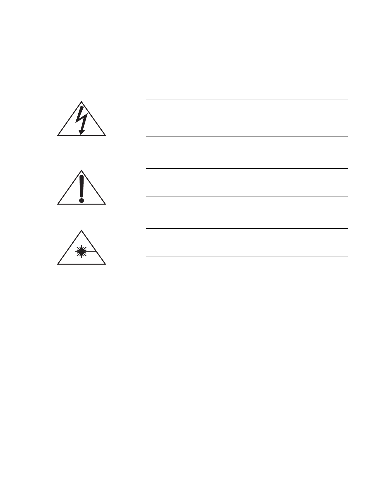
This symbol is intended to alert the operator to the presence of
dangerous voltages associated with the laser that may be of sufficient magnitude to constitute a risk of electric shock.
This symbol is intended to alert the operator to the presence of
important operating and maintenance instructions.
This symbol is intended to alert the operator to the danger of
exposure to hazardous visible and invisible laser radiation.
ix
Page 10

Libra Operator’s Manual
x
Page 11
SECTION ONE: LASER SAFETY
This user information is in compliance with section 1040.10 of
the CDRH Performance Standards for Laser Products from the
Health and Safety Act of 1968.
Use of controls or adjustments or performance of procedures
other than those specified herein may result in hazardous radiation exposure.
This laser safety section must be reviewed thoroughly prior to operating the Libra laser system. Safety instructions presented
throughout this manual must be followed carefully.
Laser Safety
Hazards
Optical Safety
Hazards associated with lasers generally fall into the following categories:
• Exposure to laser radiation that may damage the eyes or skin
• Electrical hazards generated in the laser power supply or asso-
ciated circuits
• Chemical hazards resulting from contact of the laser beam
with volatile or flammable substances, or released as a result
of laser material processing
The above list is not intended to be exhaustive. Anyone operating
the laser must consider the interaction of the laser system with its
specific working environment to identify potential hazards.
Laser light, because of its special qualities, poses safety hazards not
associated with light from conventional sources. The safe use of
lasers requires all operators, and everyone near the laser system, to
be aware of the dangers involved. Users must be familiar with the
instrument and the properties of coherent, intense beams of light.
The safety precautions listed below are to be read and observed by
anyone working with or near the laser. At all times, ensure that all
personnel who operate, maintain or service the laser are protected
1 - 1
Page 12

Libra Operator’s Manual
from accidental or unnecessary exposure to laser radiation
exceeding the accessible emission limits listed in ‘Performance
Standards for Laser Products,’ United States Code of Federal Regu-
lations, 21CFR1040 10(d).
Direct eye contact with the output beam from the laser will cause
serious damage and possible blindness.
The greatest concern when using a laser is eye safety. In addition to
the main beam, there are often many smaller beams present at
various angles near the laser system. These beams are formed by
specular reflections of the main beam at polished surfaces such as
lenses or beamsplitters. While weaker than the main beam, such
beams may still be sufficiently intense to cause eye damage.
Laser beams are powerful enough to burn skin, clothing or paint
even at some distance. They can ignite volatile substances such as
alcohol, gasoline, ether and other solvents, and can damage
light-sensitive elements in video cameras, photomultipliers and
photodiodes. The user is advised to follow the precautions below.
Recommended Precautions and Guidelines
1. Observe all safety precautions in the preinstallation and operator’s manuals.
2. All personnel should wear laser safety glasses rated to protect
against the specific wavelengths being generated. Protective
eye wear vendors are listed in the Laser Focus World, Lasers
and Optronics, and Photonics Spectra Buyer’s guides. Consult
the ANSI, ACGIH, or OSHA standards listed at the end of this
section for guidance.
3. Avoid wearing watches, jewelry, or other objects that may
reflect or scatter the laser beam.
4. Stay aware of the laser beam path, particularly when external
optics are used to steer the beam.
5. Provide enclosures for beam paths whenever possible.
6. Use appropriate energy-absorbing targets for beam blocking.
7. Block the beam before applying tools such as Allen wrenches
or ball drivers to external optics.
8. Limit access to the laser to qualified users who are familiar
with laser safety practices. When not in use, lasers should be
shut down completely and made off-limits to unauthorized
personnel.
1 - 2
Page 13
Laser Safety
9. Use the laser in an enclosed room. Laser light can remain collimated over long distances and therefore presents a potential
hazard if not confined. It is good practice to operate the laser
in a room with controlled access.
10. Post warning signs in the area of the laser beam to alert those
present.
11. Exercise extreme caution when using solvents in the area of
the laser.
12. Never look directly into the laser light source or at scattered
laser light from any reflective surface. Never sight down the
beam.
13. Set up the laser so that the beam height is either well below or
well above eye level.
14. Avoid direct exposure to the laser light. Laser beams can easily
cause flesh burns or ignite clothing.
15. Advise all those working with or near the laser of these precautions.
Electrical Safety
Recommended Precautions and Guidelines
Laser safety glasses protect the user from eye damage by
blocking light at the laser wavelengths. However, this also
prevents the operator from seeing the beam. Exercise extreme
caution even while wearing safety glasses.
Normal operation of the Libra should not require access to the
power supply circuitry. Removing the power supply cover will
expose the user to potentially lethal electrical hazards. Contact
an authorized service representative before attempting to
correct any problem with the power supply.
The following precautions must be observed by everyone when
working with potentially hazardous electrical circuitry:
1. Disconnect main power lines before working on any electrical
equipment when it is not necessary for the equipment to be
operating.
1 - 3
Page 14

Libra Operator’s Manual
2. Do not short or ground the power supply output. Protection
against possible hazards requires proper connection of the
ground terminal on the power cable, and an adequate external
ground. Check these connections at the time of installation,
and periodically thereafter.
3. Never work on electrical equipment unless there is another
person nearby who is familiar with the operation and hazards
of the equipment, and who is competent to administer first aid.
4. When possible, keep one hand away from the equipment to
reduce the danger of current flowing through the body if a live
circuit is touched accidentally.
5. Always use approved, insulated tools.
6. Special measurement techniques are required for this system.
A technician who has a complete understanding of the system
operation and associated electronics must select ground references.
Component Lasers
Maximum Accessible Radiation Level
Safety Features and Compliance with Government Requirements
The Libra system incorporates Coherent VitesseTM and Evolution
lasers as components. The beams from these lasers are hazardous.
Refer to their respective Operator’s Manuals for additional safety
information.
The Libra and its component lasers produce visible and invisible
radiation over a wavelength range of 500 to 1100 nm, with a
maximum of 40 Watts continuous wave power, and < 5 Watts
maximum energy per 30 femtosecond to 6 picosecond pulse
[CFR 1040.10 (h)(2)/ EN 60825-1/ IEC 608225-1, Clause 6].
The following features are incorporated into the instrument to
conform to several government requirements. The applicable United
States Government requirements are contained in 21 CFR,
Subchapter J, part 1040 administered by the Center for Devices and
Radiological Health (CDRH). The European Community requirements for product safety are specified in the Low Voltage Directive
(LVD) (published in 73/23/EEC and amended in 93/68/EEC). The
Low Voltage Directive requires that lasers comply with the standard
EN 61010-1/IEC 61010-1 “Safety Requirements For Electrical
Equipment For Measurement, Control and Laboratory Use” and
EN 60825-1/IEC 60825-1 “Safety of Laser Products”. Compliance
of this laser with the LVD requirements is certified by the CE mark.
TM
1 - 4
Page 15

Laser Safety
Laser Classification
Protective Housing
Safety Interlocks
Governmental standards and requirements specify that the laser
must be classified according to the output power or energy and the
laser wavelength. The Libra is classified as Class IV based on 21
CFR, Subchapter J, part 1040, section 1040.10 (d). According to the
European Community standards, Libra lasers are classified as
Class 4 based on EN 60825-1, clause 9. In this manual, the classification will be referred to as Class 4.
The laser head is enclosed in a protective housing that prevents
human access to radiation in excess of the limits of Class I radiation
as specified in the 21CFR, Part 1040 Section 1040.10 (f)(1) and
Table 1-A/EN 60825-1/IEC 60825-1 clause 4.2 except for the
output beam, which is Class 4.
The system incorporates multiple safety interlocks which activate
when the top cover of the Vitesse, Evolution, or any one of the three
top covers of the Libra is removed. An interlock fault initiation will
terminate all lasing by activating a shutter mechanism as well as
removing power from the infrared diode lasers in each power supply.
While installed, the interlock defeats are directly visible by anyone
near the laser. It is not possible to replace the laser cover while the
interlocks are installed
Laser Radiation Emission Indicators
Beam Attenuator
The laser interlocks should be defeated only for the purpose of maintenance and service by trained personnel aware of the hazards
involved. Extreme caution must always be observed when operating
the laser with its covers removed. [CFR 1040.10 (f)(2)/
EN 60825-1/IEC 608225-1, Clause 4.3].
The LASER EMISSION LED on the laser head illuminates approximately 30 seconds before laser emission can occur. The indicator is
visible without exposing the operator to laser emission. Amber light
is used which is visible while wearing the proper type of safety
glasses [CFR 1040.10(f)(5)/EN 60825-1/IEC 60825-1, clause 4.6].
Internal shutters within the Vitesse and Evolution lasers prevent
exposure to all laser radiation without removing power from the
system [CFR 1040.10 (f)(6)/EN 60825-1/IEC 60825-1, clause 4.7].
1 - 5
Page 16
Libra Operator’s Manual
Operating Controls
Manual Reset Mechanism
The laser controls are positioned so that the operator is not exposed
to laser emission while manipulating the controls [CFR
1040.10(f)(7)/EN 60825-1/IEC 60825-1, clause 4.8].
Following an interlock fault or unexpected loss of electrical power,
laser operation requires manual clearing of the fault condition(s)
[CFR 1040.10(f)(10)/EN 60825-1/IEC 60825-1, clause 4.11].
Use of controls or adjustments or performance of procedures
other than those specified in the manual may result in hazardous
radiation exposure.
Use of the system in a manner other than that described herein
may impair the protection provided by the system.
Location of Safety Labels
Electromagnetic Compatibility
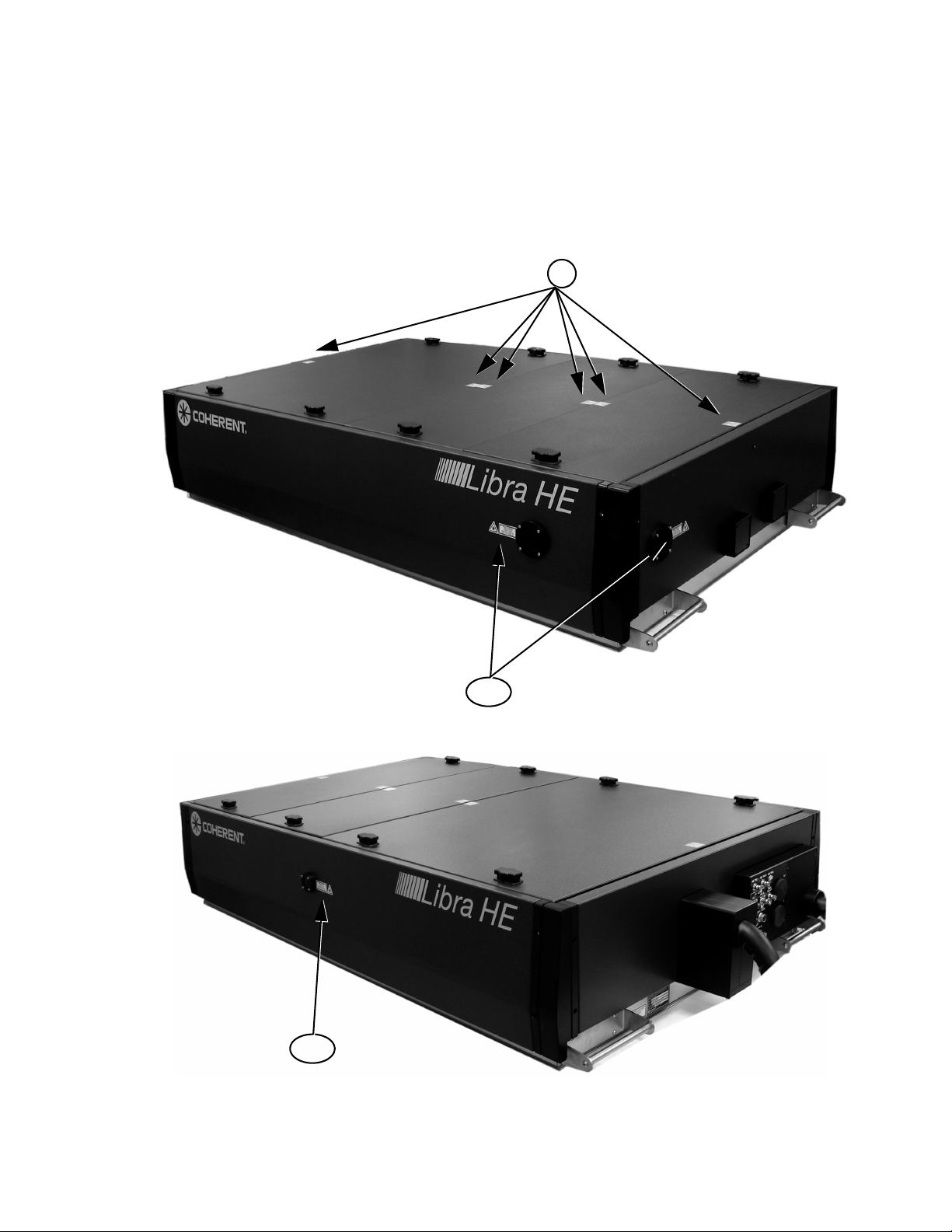
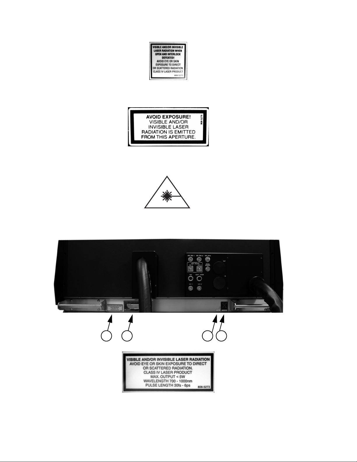
Refer to Figure 1-1 for the location of all safety labels. These include
warning labels indicating removable or displaceable protective
housings, apertures through which laser radiation is emitted, and
labels of certification and identification [CFR 1040.10(g), CFR
1040.2, and CFR 1010.3/ EN 60825-1/IEC 60825-1, Clause 5].
The European requirements for Electromagnetic Compliance
(EMC) are specified in the EMC Directive (published in
89/336/EEC).
Conformance to the EMC requirements is achieved through compliance with the harmonized standards EN55011 (1991) for emission
and ENC50082-1 (1992) for immunity.
The laser meets the emission requirements for Class B, group 1 as
specified in EN55011 (1991).
Compliance of this laser with the EMC requirements is certified by
the CE mark.
1 - 6
Page 17
Laser Safety
Waste Electrical and Electronic Equipment (WEEE, 2002)
The European Waste Electrical and Electronic Equipment (WEEE)
Directive (2002/96/EC) is represented by a crossed-out garbage
container label (see Figure 1-1). The purpose of this directive is to
minimize the disposal of WEEE as unsorted municipal waste and to
facilitate its separate collection.
1
2, 3
2, 3
Figure 1-1. Libra Safety Labels
1 - 7
Page 18
Libra Operator’s Manual
1. INTERLOCK DEFEAT LABEL
2. LASER APERTURE LABEL
3. RADIATION HAZARD WARNING LABEL
4 5 6 7
4. RADIATION OUTPUT CHARACTERISTICS LABEL
Figure 1-1. Libra Safety Labels (Continued)
1 - 8
Page 19
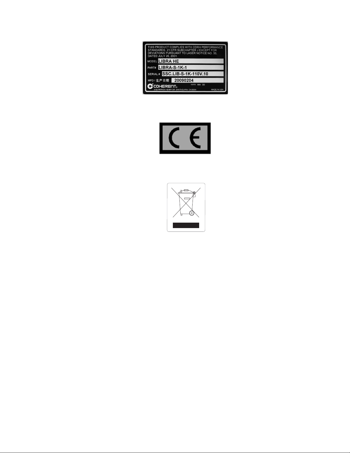
5. IDENTIFICATION LABEL
6. CE COMPLIANCE LABEL
Laser Safety
7. WEEE COMPLIANCE LABEL
Figure 1-1. Libra Safety Labels (Continued)
1 - 9
Page 20
Libra Operator’s Manual
8
8. ELECTRICAL HAZARD WARNING LABEL
Figure 1-1. Libra Safety Labels (Continued)
1 - 10
Page 21

Laser Safety
Sources of
Additional
The following are sources for additional information on laser safety
standards and safety equipment and training.
Information
Laser Safety Standards
Safe Use of Lasers (Z136.1)
American National Standards
Institute (ANSI)
1430 Broadway
New York, NY 10018
Tel: (212) 354-3300
A Guide for Control of Laser Hazards
American Conference of Governmental
and Industrial Hygienists (ACGIH)
6500 Glenway Avenue, Bldg. D-7
Cincinnati, OH 45211
Tel: (513) 661-7881
Occupational Safety and Health
Administration (OSHA)
U.S. Department of Labor
200 Constitution Avenue N.W.
Washington, DC 20210
Laser Safety Guide
Laser Institute of America
12424 Research Parkway, Suite 130
Orlando, FL 32826
Tel: (407) 380-1553
Equipment and Training
Laser Focus Buyer’s Guide
Laser Focus World
One Technology Park Drive
P.O. Box 989
Westford, MA 01886-9938
Tel: (508) 692-0700
Lasers and Optronics Buyer’s Guide
Lasers and Optronics
301 Gibraltar Dr.
P.O. Box 650
Morris Plains, NJ 07950-0650
Tel: (210) 292-5100
Photonics Spectra Buyer’s Guide
Photonics Spectra
Berkshire Common
Pittsfield, MA 01202-4949
Tel: (413) 499-0514
1 - 11
Page 22

Libra Operator’s Manual
1 - 12
Page 23
Description and Layout
SECTION TWO: DESCRIPTION AND LAYOUT
Libra System
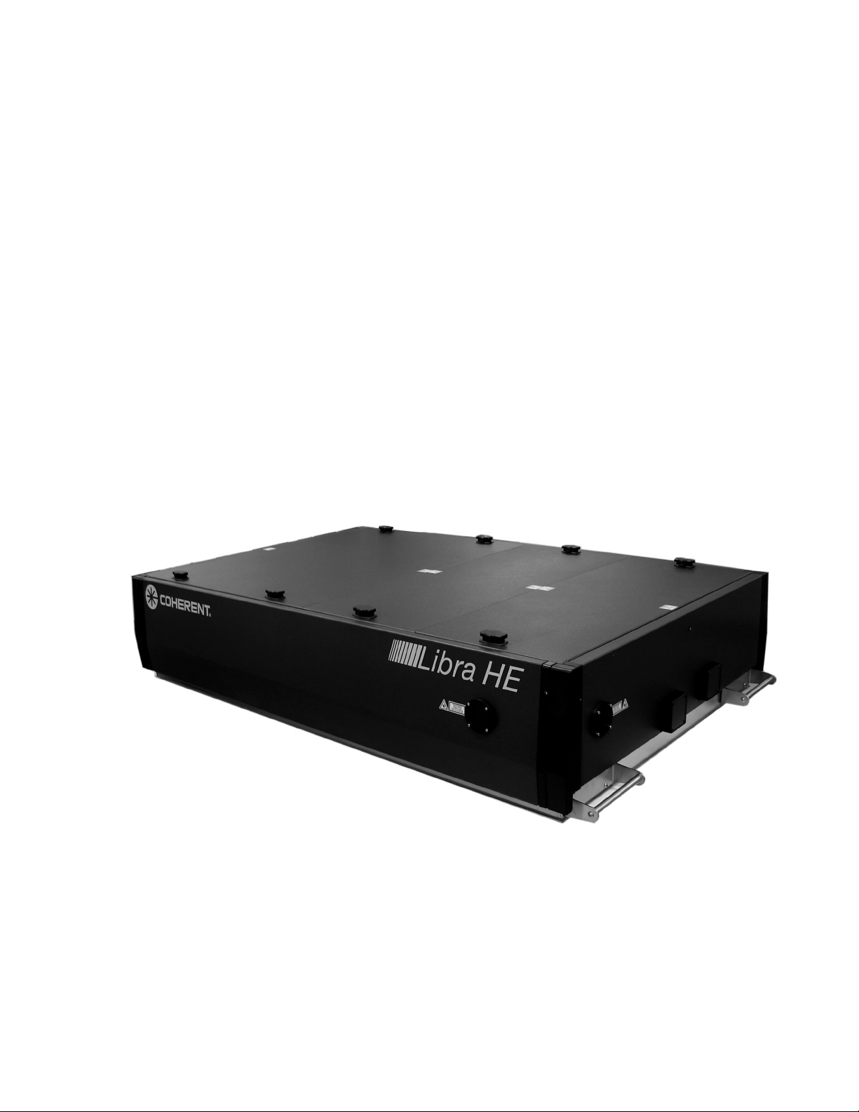
The Libra is an all-in-one ultrafast oscillator and regenerative amplifier laser system. Solid-state laser technology is incorporated into a
compact optical enclosure, providing reliable operation over thousands of hours.
The Libra laser system consists of six primary components:
• Libra optical bench assembly
• Synchronization & delay generator (SDG)
• Vitesse power supply
• Evolution power supply
• Closed-loop water chiller
• Laptop computer with control software
Figure 2-1. Libra Optical Bench Assembly
2 - 1
Page 24

Libra Operator’s Manual
Libra Optical Bench Assembly
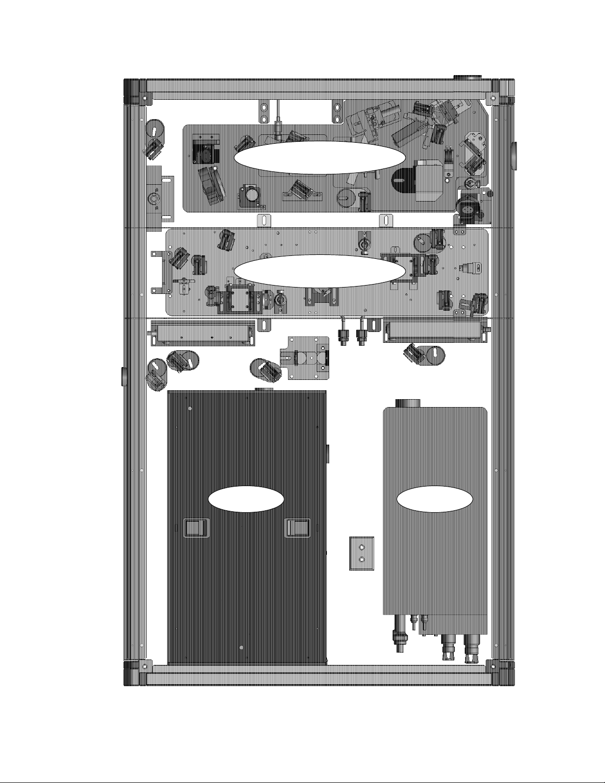
The Libra optical bench assembly comprises four modules (see
Figure 2-2 on page 2-3):
• Vitesse seed laser
• Evolution pump laser
• Regenerative amplifier (RA)
• Stretcher/Compressor
The Coherent VitesseTM serves as the seed laser for the Libra system.
This module includes a modelocked Ti:Sapphire oscillator cavity
pumped by the Coherent VerdiTM, a continuous-wave diode-pumped
green laser.
The Evolution is a diode-pumped second-harmonic Q-switched
laser. Operating at 527 nm and a single-kHz repetition rate, it
provides the pump power to the amplifier module. The Vitesse and
Evolution are described in detail in their respective Operator’s
Manuals.
The Regenerative Amplifier is based on the Coherent Legend
EliteTM platform. Designed in a compact, enclosed module with
active cooling, the amplifier exhibits excellent stability and reduced
sensitivity to environmental temperature changes. Included in this
design is the Coherent Synchronization and Delay Generator
(SDGTM), whose operation is also described in its own Operator’s
Manual.
Optical Component Labels
The stretcher and compressor are also contained within a robust
modular enclosure. These are also based on the Legend Elite grating
and curved mirror configuration, but with a more compact footprint.
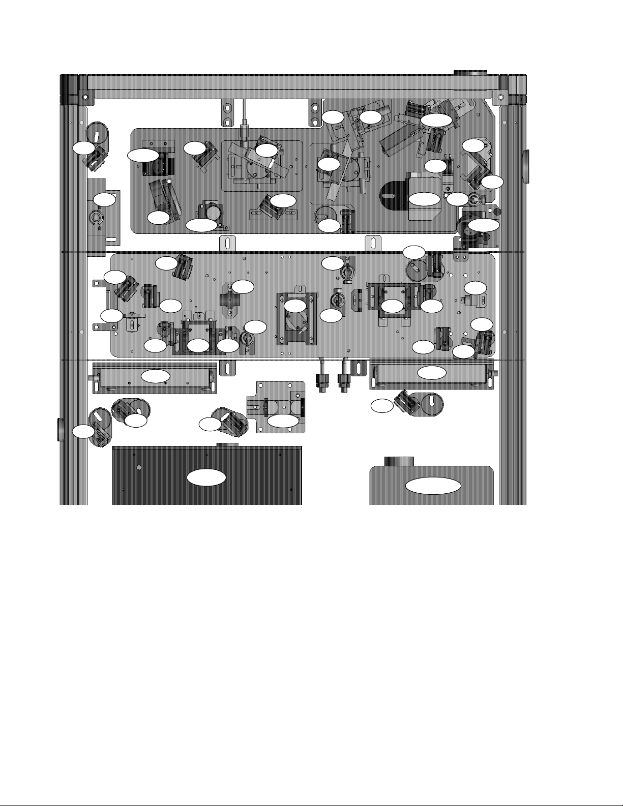
Figure 2-3 and Table 2-1 show a layout diagram, component labels,
and descriptions.
2 - 2
Page 25
Description and Layout
Stretcher / Compressor
Regenerative Amplifier
Vitesse
Evolution
Figure 2-2. Libra Optical Bench Assembly Block Diagram
2 - 3
Page 26
Libra Operator’s Manual
SM2
SBS
FI
PM3
PL3
SM5-6
PM2
SM3
RM5
RM1
PCD1
RM3
SM7
SM8-9
PC1
SM1
RWP
RP
RI1
SG
SM10
PL1-2
RTS
SM4
CG
RM7
RI3
RI2
SPD
PM1
PC2
CM4-5
RM6
RM4
RM2
PCD2
CM2-3
CM1
CDI
CM6
RI4
RM8-9
RPD
PM4
PL4
Vitesse
Figure 2-3. Libra Optical Layout Diagram
2 - 4
Evolution
Page 27

Table 2-1. Component Labels and Descriptions
Description and Layout
SM1, SM2, SM7,
SM10 Stretcher
Routing Mirror
SBS Stretcher Beam
Splitter (50%)
FI Faraday Isolator PL3, PL4 Pump
SG Stretcher Grating PCD1, PCD2 Pockels Cell
SM3 Stretcher Large
Curved Mirror
SM4 Stretcher Wide
Flat Mirror
SPD Stretcher
Photodiodes
SM5-6 Stretcher
Vertical Retroflector
PM1-PM4 Pump Routing
Mirror
PL1-2 Pump Telescope RM2, RM3 Regen Cavity
Focusing Lens
RM1, RM4 Regen Cavity
End Mirror
Pump-through Folding
Mirror
PC1, PC2 Regen
Pockels Cell
Driver
RWP Regen Waveplate CM4-5 Compressor
RI1-RI4 Regen
Alignment Iris
RTS Regen Ti:Sapphire
crystal
RP Regen Polarizer
CM1 Compressor Routing
Mirror
CDI Compressor Double
Iris
CG Compressor Grating
CM2-3 Compressor Hori-
zontal Retroreflector
Vertical Retroreflector
CM6 Compressor Output
Routing Mirror (optional)
SM8-9
Stretcher Periscope
RM5-RM6 Regen Output
Telescope
RM7 Regen Output
Routing Mirror
RM8-9 Regen Output
Periscope
RPD Regen Photodiode
2 - 5
Page 28

Libra Operator’s Manual
Synchronization and Delay Generator (SDG)
Power Supplies
Water Chiller
Laptop Computer
The SDG controls the precise timing of the RA Pockels cells. It
contains a high-speed power supply for the Pockels cells as well as
a bandwidth detector (BWD) circuit, which serves as an interlock to
protect the laser from operation at narrow bandwidth.
The Libra system includes two individual power supplies, for the
Vitesse and Evolution modules. Refer to the Vitesse and Evolution
Operator’s Manuals for additional information.
The closed-loop water chiller dissipates the heat generated by the
system and stabilizes the Vitesse, Evolution, and amplifier cavity.
The temperature is optimized in the factory and is typically ~21 ° C.
Refer to the chiller operator’s manual for further details.
The system is shipped with a laptop computer with Windows-based
control software for the Vitesse, Evolution, and SDG already
installed.
Specifications
These components may be controlled remotely through RS-232
serial connections on the Vitesse power supply, Evolution power
supply, and SDG rear panel. Multiple serial-to-USB adaptors are
used for simultaneous control from one computer.
The Customer Data Sheet shipped with each Libra provides a
detailed description of system performance. Specifications for all
Coherent products can be found at
www.Coherent.com.
2 - 6
Page 29
SECTION THREE: INSTALLATION
Installation
Receiving and Inspection
Vitesse and Evolution Lasers
Control Computer
Inspect shipping containers for signs of rough handling or damage,
and immediately report any damage to the shipping carrier and to
Coherent.
The Libra must be installed by authorized Coherent personnel.
Do not remove the system from its shipping containers.
Refer to the Vitesse and Evolution Operator’s Manuals for additional installation information.
Installation Requirements
The Libra was manufactured and tested using the computer and
control software that shipped with the laser. Coherent does not
support the use of other computers or software to control the
Libra; doing so voids the warranty and may cause damage to the
laser.
Some planning is required before installing the Libra:
• Select a suitable location for all system components.
• Provide the required utilities (listed below).
• Provide the appropriate diagnostic equipment.
3 - 1
Page 30

Libra Operator’s Manual
Location
Utility Requirements
The Libra must rest on an optical table. Coherent recommends that
the Libra be located in a laboratory environment; that is, in a room
free of dust, drafts, and which does not exhibit large temperature
fluctuations. Although the Libra is designed to be insensitive to
environment temperature, Coherent recommends that the temperature be controlled within ± 2 ° C throughout the day for optimal
system performance.
The Libra requires a minimum table space of about 4x3ft.
(1.2 x 0.90 m). It is the responsibility of the customer to determine
the best location for the Libra. The Libra must be placed in a position
that allows easy access for service-related activities.
System electrical requirements are found in Table 3-1.
Table 3-1. Libra Electrical Requirements
110 ± 10 V 50/60 HZ (AMPS) 220 ± 20 V 50 HZ (AMPS)
Vitesse Power Supply 15 10
Evolution Power Supply 15 10
Chiller 15 10
SDG 1 0.5
Laptop computer 1.5 1
Dimensions
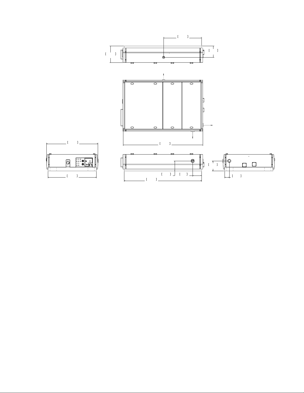
Figure 3-1 gives the dimensions of the optical bench assembly.
Refer to the respective Operator’s Manuals for the dimensions of
other components.
3 - 2
Page 31
Mechanical Specifications
Libra HE
10.31 in
26.19 cm
Right Side View
Top View
Opt. Seed
Output
23.54 in
59.79 cm
7.06 in
17.92 cm
Output
Installation
31.88 in
80.98 cm
Rear View
30.00 in
76.2 cm
Water and Cabling Connections
Cooling Water
Opt.
5.5 in
13.97 cm
Output
6.26 in
15.90 cm
Left Side View
48.00 in
121.92 cm
49.44 in
125.57 cm
6.26 in
15.91 cm
Figure 3-1. Libra Optical Bench Assembly Dimensions
The Libra is shipped with all of the internal water lines connected.
The only connections that are necessary are the two chiller external
water hoses. Each hose has an arrow on it that indicates the water
flow direction.
2.84 in
7.22 cm
Front View
1. Connect the chiller output water hose to the IN connector on
the Libra optical bench assembly.
2. Connect the chiller return water hose to the OUT connector on
the Libra optical bench assembly.
3 - 3
Page 32
Libra Operator’s Manual
Cable Connections
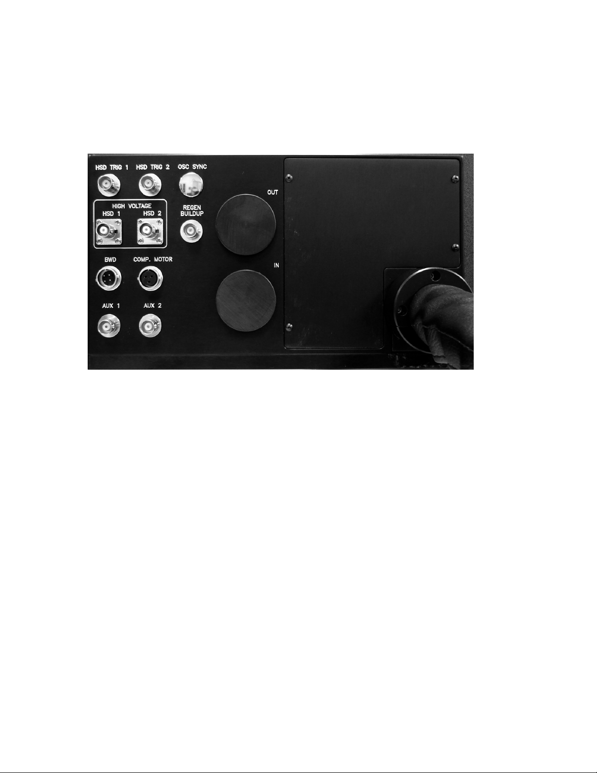
Figures 3-1 shows the rear panel of the Libra optical bench
assembly. Refer to the Vitesse, Evolution, and SDG Operator’s
Manuals for figures pertaining to these components.
Make the following cable connections:
Figure 3-2. Libra Optical Bench Assembly Rear Panel Connections
Libra Rear Panel Connections
Standard BNC connections
1. “HSD Trig 1” on the Libra rear panel, to “Out 1 Delay ns” on
the SDG front panel.
2. “HSD Trig 2” on the Libra rear panel, to “Out 2 Delay ns” on
the SDG front panel.
3. “Osc Sync” on the Libra rear panel to “RF Sync” on the SDG
rear panel.
4. "Regen Build-Up" on the Libra rear panel to the channel input
of an oscilloscope. Use a time base of 100 or 200 ns per division to monitor the RA intracavity buildup (pulse train) during
system operation.
5. “Sync out Delay ns” on the SDG front panel, to the trigger
input of an oscilloscope. Trigger the scope from this signal.
6. “Aux 1” and “Aux 2” are unused.
3 - 4
Page 33

Installation
High Voltage BNC connections
Verify that the SDG main power switch is OFF before contacting
the High Voltage (HV) connectors on the SDG rear panel.
1. “High Voltage HSD 1” on the Libra rear panel to “High
Voltage H.V. 1” on the SDG rear panel.
2. “High Voltage HSD 2” on the Libra rear panel to “High
Voltage H.V. 2” on the SDG rear panel.
Remaining Cables
1. Connect the three-pin cable assembly from the compressor
stage remote control to “COMP. MOTOR” on the Libra rear
panel.
2. Connect the four-socket cable assembly to “BWD” on the
Libra rear panel, and to “BWD” on the SDG rear panel.
Evolution Power Supply Connections
Vitesse and SDG Computer Connections (Optional)
Vitesse and Evolution Umbilical Cables
Large umbilical cables connect from the Libra rear panel to the
Vitesse and Evolution power supplies. Do not disconnect or disasssemble these cables.
1. “Q-SW Sync Out” on the Evolution power supply rear panel,
to “Trigger In” on the SDG rear panel.
2. “USB” on the Evolution power supply front panel, to a USB
port on the computer.
The Vitesse power supply and SDG feature RS-232 serial ports for
remote control over these components. USB-to-Serial adaptors may
be used to simultaneously connect the Vitesse, Evolution, and SDG
to the computer.
Control software is shipped with the system. See the “Readme” file
for additional information about software features and operation.
3 - 5
Page 34

Libra Operator’s Manual
Power Connections Connect the following equipment to facility power:
• Vitesse power supply
• Evolution power supply
• SDG
• Chiller
• Computer
Grating Installation
External Interlock
The Libra is shipped with the stretcher and compressor gratings in
separate containers. The gratings are installed by Coherent field
service engineers or representatives.
An external interlock connector is provided on the SDG rear panel.
When the toggle switch is in the ENABLE position (up), the system
will not operate with this circuit open. In the event of an interlock
fault during normal operation, the Pockels cells are disabled which
terminates Libra output. This circuit may be disabled by toggling the
switch down.
Alternatively, the interlock connector may be wired to an external
circuit such as a door switch. Many types of switches may be used,
but the switch should have its contacts closed when it is safe to
operate the laser and open when it is not safe.
The Vitesse and Evolution power supplies are also equipped with
interlock connectors, as described in their respective Operator’s
Manuals. The system is shipped with interlock defeats installed over
these connectors.
SDG Toggle Switches
1. The BWD toggle switch on the SDG rear panel should be set
to ON (up position).
2. If an external interlock is connected, set the INTERLOCK
toggle switch to ENABLE (up position). If no external interlock circuit is connected, set it to the down position.
3 - 6
Page 35

Controls and Indicators
SECTION FOUR: CONTROLS AND INDICATORS
Vitesse, Evolution, and SDG
Vitesse, Evolution, and SDG Control Software
The Vitesse and Evolution lasers, as well as the Synchronization and
Delay Generator (SDG), are described in detail in separate Operator’s Manuals. Refer to these for descriptions of their controls and
indicators.
Control software for these components is shipped with the system.
Refer to the “Readme” file for information about software features
and operation.
4 - 1
Page 36

Libra Operator’s Manual
4 - 2
Page 37
SECTION FIVE: DAILY OPERATION
All personnel in the area must wear laser safety glasses to
protect against laser radiation. Read Section One: Laser Safety
and be familiar with proper laser safety practices. Please contact
Coherent customer service (800-367-7890) with any questions or
potential issues concerning laser safety.
Laser safety eye wear must be rated to protect against the
following wavelengths:
Table 5-1. Wavelengths of Radiation Generated by the Libra
LIBRA CONDITION WAVELENGTHS
Daily Operation
Covers in place (normal operation) 750 to 850 nm
Optical bench assembly cover removed 525 to 535 nm, 700 to 900 nm
Evolution or Vitesse head cover removed 525 to 535 nm, 750 to 850 nm
Fiber optic cable disconnected 808 nm, 1064 nm
The Libra is normally operated with the laser head and power
supply covers in place. Operation of the laser with the head
cover removed allows access to hazardous visible and invisible
radiation. Removal of the power supply cover allows access to
dangerous voltage and current levels in addition to laser radiation. Covers should only be removed for service and maintenance by trained personnel aware of the potential hazards.
Wear safety glasses of OD 5 or greater for all lasing wavelengths
at all times when operating this or any laser system.
5 - 1
Page 38
Libra Operator’s Manual
Control Computer
The Libra was manufactured and tested using the computer and
control software that shipped with the laser. Coherent does not
support the use of other computers or software to control the
Libra; doing so may cause damage to the laser and voids the
warranty.
System Activation Procedure
Initialization of the Libra consists of several steps in sequence:
The Vitesse and Evolution lasers have different procedures for a
cold vs. warm start. Refer to the Vitesse and Evolution Operator’s Manuals for start procedures for these lasers.
1. Turn on the main power switch of the SDG and power up the
computer.
2. Activate the Vitesse and Evolution lasers, including the water
chillers.
3. Allow a few minutes for the pump and seed lasers to stabilize.
Verify that the Vitesse is modelocked and operating at normal
bandwidth.
4. Verify that the bandwidth interlock circuit is enabled, and that
the BWD PD lights on the front panel of the SDG are active.
5. Press the BWD RESET button.
6. Activate each Pockels cell by pressing the ENABLE buttons
on the SDG. The red LED above each button is lit when that
Pockels cell is active.
7. Observe the regen pulse train on an oscilloscope, and monitor
regen output characteristics as necessary. Coherent recommends periodic recording of system parameters.
5 - 2
Page 39

Daily Operation
System Shutdown Procedure
Perform the following steps to shutdown the Libra:
Refer to the Vitesse and Evolution Operator’s Manuals for shutdown procedures for these lasers.
1. Deactivate the Pockels cells by pressing the ENABLE buttons
on the SDG front panel. The red LEDs will turn off.
2. Shut down the Evolution and Vitesse lasers, including the
water chillers.
3. Press the yellow EXIT buttons on the software control
windows before quitting the program. This saves any changes
made since the last time the software was opened.
4. Turn off the main power switch of the SDG.
5. Turn off any auxiliary or diagnostic equipment.
Optional Vitesse Output
The Libra features a beamsplitter (SBS in Figure 2-3 on page 2-4)
which allows direct sampling of the Vitesse seed beam. Unblock the
side port to access this beam.
5 - 3
Page 40

Libra Operator’s Manual
Data Log Template
DATE:__/ __ /__
TIME:
The following table may be used as a guide for logging system
settings and output characteristics:
AB TEMPERATURE:LAB HUMIDITY:
L
VERDI [SEED LASER PUMP] SEED LASER
Verdi output power W Vitesse modelocked power mW
Diode current A Vitesse bandwidth nm
Diode hours
EVOLUTION [AMPLIFIER PUMP] LIBRA
Output power W Output power W
Diode current A Delay 1 setting ns
Diode hours H Delay 2 setting ns
o
LBO temperature
DATE:__/ __ /__
TIME:
LAB TEMPERATURE:LAB HUMIDITY:
C Output bandwidth nm
Pulse width fs
VERDI [SEED LASER PUMP] SEED LASER
Verdi output power W Vitesse modelocked power mW
Diode current A Vitesse bandwidth nm
Diode hours
EVOLUTION [AMPLIFIER PUMP] LIBRA
Output power W Output power W
Diode current A Delay 1 setting ns
Diode hours H Delay 2 setting ns
o
LBO temperature
C Output bandwidth nm
Pulse width fs/ps
DATE:__/ __ /__
IME:
T
LAB TEMPERATURE:LAB HUMIDITY:
VERDI [SEED LASER PUMP] SEED LASER
Verdi output power W Vitesse modelocked power mW
Diode current A Vitesse bandwidth nm
Diode hours
EVOLUTION [AMPLIFIER PUMP] LIBRA
Output power W Output power W
Diode current A Delay 1 setting ns
Diode hours H Delay 2 setting ns
o
LBO temperature
C Output bandwidth nm
Pulse width fs/ps
5 - 4
Page 41
Maintenance and Troubleshooting
SECTION SIX: MAINTENANCE AND
ROUBLESHOOTING
T
The Libra has been designed to minimize required maintenance.
However, Coherent recommends several routine operations to maintain optimal performance over the lifetime of the system.
The procedures described in this section must be performed
only by qualified personnel. Incorrect implementation of these
procedures is a safety hazard and can cause permanent damage
to the system. Damage caused by operator error is not covered
under warranty. Contact Coherent Service with any questions
or concerns before attempting maintenance procedures.
Chiller Maintenance
Maintenance procedures often require operation of the Libra
with the covers removed, which increases the risk of exposure to
hazardous radiation and electrical current and voltage levels.
Refer to Section One: Laser Safety for additional information.
Refer to the other Operator’s Manuals shipped with the system
for periodic maintenance of Libra components.
The fluid level, air filter condition, and pump strainer condition
should be inspected on a regular basis. Maintenance intervals will
depend on system use; under typical conditions replace the filters
every three months, and drain and replace the coolant every year.
Contact Coherent Service if particulate matter is observed in the
coolant reservoir. The Lytron web site contains extensive information on maintaining and troubleshooting chillers.
6 - 1
Page 42
Libra Operator’s Manual
Cleaning Optics
Proper cleaning is necessary to maintain optimum performance of
high-grade optics. Laser optical components are routinely exposed
to high energy levels. When optical surfaces are clean, this energy is
either reflected or transmitted. When optical coatings are contaminated, however, contaminants on the optical surface absorb energy,
creating hot-spots that can burn the precision coating and dramatically degrade performance.
Cleaning frequency is dependent on the humidity level and
cleanliness of the laboratory environment as well as system duty
cycle. Routine cleaning should generally be performed every
6 to 12 months.
Contaminants include particles that may fall on the optical surface,
condensation from surrounding vapors, or oils from the skin (even
from the cleanest hands). Exercise extreme care when handling and
cleaning optics.
Contaminated optics are the cause of many of the preventable problems in the operation of lasers. Keep the laboratory environment
clean and free of dust to help avoid degradation of performance due
to contamination.
Observation of Contamination
Spectroscopic / spectrophotometric-grade or electronic-grade methanol and acetone are the recommended solvents for cleaning optics.
Other solvents and other grades can leave residues or otherwise
degrade optical coatings.
Do not store solvent bottles capped with rubber droppers. Over
time the solvent will dissolve the rubber and become impure.
Lens tissue is also required. When cleaning optics with lens tissue,
use each tissue for only one pass in one direction and then discard it.
Repeat if necessary with a clean tissue, going in the same direction
as the original swipe. Reusing tissue or going back in the opposite
direction may damage the optic by dragging loose particles across
the surface.
Laser optical coatings are generally designed to reflect a very high
percentage of the incident light. Foreign material, however, will
scatter laser light and cause a bright spot to appear on an optical
surface.
6 - 2
Page 43
Maintenance and Troubleshooting
In many cases, a near-IR laser beam will appear very dim or even
invisible to the naked eye when the optic is clean. A highly visible
red spot (particularly on one optic in comparison to others in the
cavity) is an indication of a contaminated optic. An IR viewer will
also reveal contamination as a bright spot on one optic in comparison to the rest.
In cases of severe damage, a mark may be seen with no laser beam
present by shining a flashlight at various incident angles to the optic.
Never clean a gold surface or diffraction grating (stretcher and
compressor gratings in the Libra). Additional damage to the
optical surface will result. If you feel that optical damage has
occurred or cleaning of these optics is necessary, contact
Coherent Service.
Cleaning Installed Optics
In the case of dust visible on an optic, blowing a puff of air across an
optic may be used as an initial step in cleaning. However, do not use
compressed air that contains propellants, do not blow with your
mouth, and do not use anything that contains any other residue or
that may cause condensation on the optic. Also, be careful not to stir
up dust in the air that will then settle on the optic.
The following procedure is used to clean optics while in place in the
laser head. When possible, clean the optic while it is installed in the
laser head to minimize disturbance to the optical alignment.
1. Record the output power, and then shut down or block any
laser beams incident on the optic.
2. Neatly fold a sheet of lens tissue several times into a rectangular shape, ending with a folded edge that is 1/4 in. to 3/4 in.
long, clamped with a hemostat, with approximately 1/8 in. of
the tissue paper protruding from the side of the hemostat. To
avoid scratching an optic, ensure that the hemostat is not
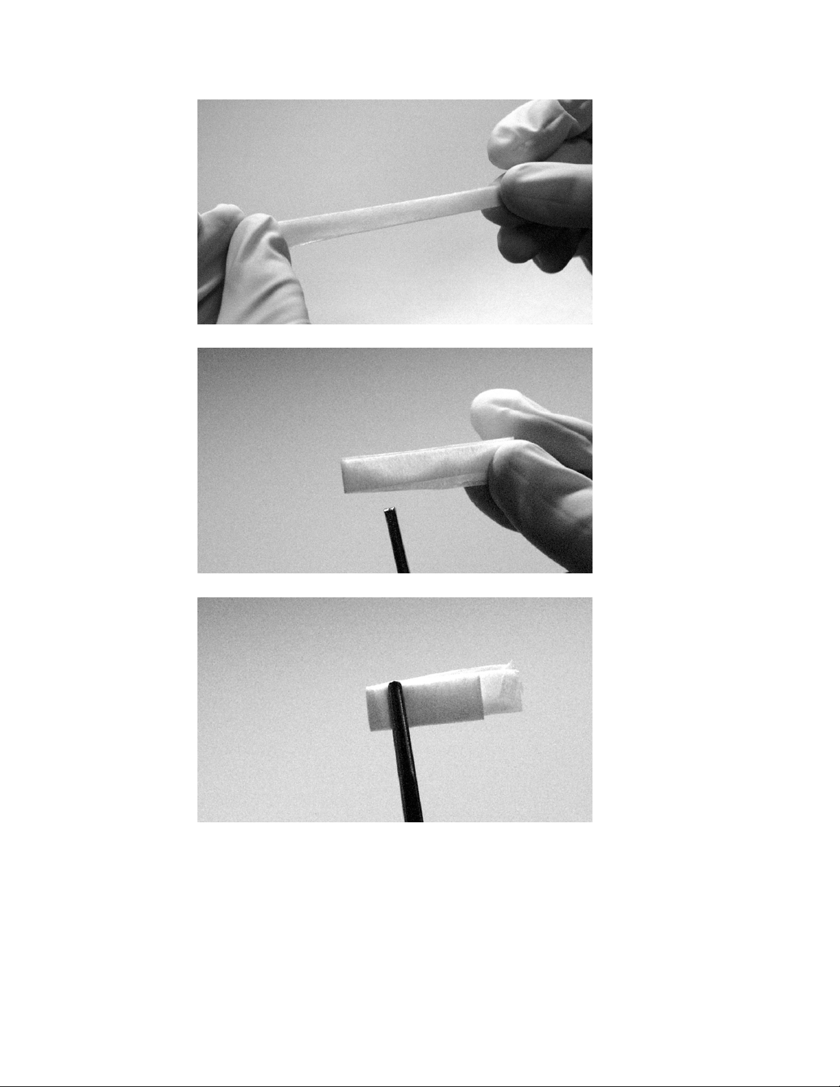
clamped too close to the fold of the lens tissue. Example photographs are given in Figure 6-1.
While folding the tissue, be careful not to contaminate it with
soiled or oily fingers in the place the tissue will eventually touch
the optic to be cleaned.
6 - 3
Page 44
Libra Operator’s Manual
Figure 6-1. Folding and Clamping of Lens Tissue
3. Wet the tissue with several drops of methanol or acetone.
Shake the hemostats to remove excess solvent.
4. Wipe across the optic in one direction. Use enough pressure to
make even contact between the tissue and the optic, but no
6 - 4
Page 45

Maintenance and Troubleshooting
more. Use extreme care for those optics that might dislodge or
break off of their mounts.
5. Repeat the above steps until the optic is clean, using a new lens
tissue for each pass.
Cleaning Removed Optics
Cleaning the Ti:Sapphire Crystal
The following technique is recommended for optics that have been
removed from the laser or are being put into the laser.
1. Hold the optic element gently by the edge or place it on a clean
work surface covered with lens tissue.
2. Place a few drops of acetone or methanol on one end of the
lens tissue.
3. Place the wet end of the lens tissue on the optic and pull it
across the optic in one direction only. Ensure that the optic
does not move by holding it by the sides while doing this. Do
not rub the tissue back and forth. Note that the dry part of the
tissue helps remove any acetone or methanol residue.
4. Repeat the above steps until the optic is clean, using a new lens
tissue for each pass.
The Ti:Sapphire crystal in the Libra RA does not have an optical
coating. The material is very hard and very difficult (but not impossible) to scratch. It is acceptable to apply more pressure when
cleaning the crystal than when cleaning other optics. Furthermore, if
a contaminant is not removed with a single wipe, it is acceptable to
use a back-and-forth motion on the crystal surface. Do not do this for
other optics, whether coated or uncoated.
Cleaning the Pockels Cells
The optical surfaces of the Pockels cells are coated and can be safely
cleaned using the same process as cleaning installed optics.
However, it is very difficult to reach the optical surfaces when the
Pockels cell is installed in the laser. In order to properly clean the
surfaces it is necessary to remove them. For this reason Coherent
does not recommend the cleaning of the Pockels cells. If you are
concerned about the cleanliness of the Pockels cells, please contact
Coherent Service.
6 - 5
Page 46

Libra Operator’s Manual
Troubleshooting
The following table lists first-level troubleshooting procedures for
symptoms associated with Libra operation. Contact Coherent
Service with any questions.
Table 6-1. Troubleshooting Reference List
PROBLEM TROUBLESHOOTING REFERENCE
Pulse Energy
No output Table 6-2
Low power Table 6-3
Power instability Table 6-4
Pulse duration
Long pulse width Table 6-5
Side lobes or “wings” Table 6-5
Pulse “breathing” Table 6-6
Instability & Jitter
Power instability Table 6-4
Pulse duration instability Table 6-6
Build-up trace not in sync (time jittering) Table 6-4
SDG not locked on repetition rate Tab le 6-4
SDG Sync error Table 6-4
Contrast Ratio
Pre-pulse Table 6-7
Post-pulse Table 6-7
Beam propagation
Divergence (beam not collimated) Table 6-8
Beam pointing instability Table 6-6
Spatial beam profile
Hot spots and non-uniformity Table 6-9
Optical spectrum
Center wavelength shift Table 6-10
Reduced bandwidth Table 6-10
6 - 6
Page 47

Maintenance and Troubleshooting
Table 6-1. Troubleshooting Reference List (Continued)
PROBLEM TROUBLESHOOTING REFERENCE
Modulation in the spectrum Table 6-11
Spatial chirp
In the stretcher See “Stretcher Spatial Chirp Removal” on page 7-12
In the compressor See “Compressor Spatial Chirp Removal” on page 7-36
Active Fault
Vitesse, Evolution, or SDG fault See Vitesse, Evolution, or SDG Operator’s Manual
Pulse Energy
Table 6-2. No Libra Output
POSSIBLE CAUSE CORRECTIVE ACTION
Vitesse and/or Evolution
Seed and/or pump laser not activated
Active Fault 1. Check that all covers are firmly in place and secured.
Evolution not at correct current
setting
Evolution Q-Switch mode incorrect
SDG
Perform turn-on procedures as described in the respective Operator’s
Manual.
2. Check the front panel display on Vitesse power supply and Fault LED
on Evolution power supply. See Vitesse or Evolution Operator’s Manual
for more information.
Verify the Evolution current setting as shown in the installation report or more
recent log entry.
Access the Evolution Control software and set the Q-Switch mode to
“Internal.”
SDG Out 1 or Out 2 disabled 1. Press RESET and ENABLE buttons as necessary on the SDG.
2. Look for the RGA pulse train on an oscilloscope.
3. Verify that the PD1 and PD2 LEDs on the SDG front panel are lit.
4. Verify the bandwidth of the seed laser.
5. Verify AC power to SDG.
6. Verify that BWD ENABLE on the SDG rear panel is in the up position.
7. Check alignment to the BWD photodiodes. Adjust the photodiodes if
necessary.
6 - 7
Page 48

Libra Operator’s Manual
Table 6-2. No Libra Output (Continued)
POSSIBLE CAUSE CORRECTIVE ACTION
Open interlock circuit If no external interlock circuit is connected to the back of the SDG, verify that
the toggle switch is in the “down” position (not enabled).
If an external interlock circuit is being used, verify that it is closed.
SDG in “single shot” mode instead
of “continuous”
SDG Sync Error 1. Verify that the seed laser is modelocked at normal operating power.
Other
RGA not lasing 1. See “SDG Sync Error” above.
Press the “Mode” button on the SDG front panel to light the “Continuous”
LED.
2. Verify that the rep rate is locked at the normal operating frequency (e.g.
1 kHz) and that sync is enabled (Sync Enable LED).
3. Press the “Sync Enable” button on the SDG front panel to light the Sync
Enable LED.
4. If Sync Error persists (Error LED remains lit), check the RF sync signal
on an oscilloscope. The peak-to-peak amplitude must be 200 mV or
greater with 50 Ohm termination.
5. Only after verifying the RF Sync signal amplitude, adjust the R71 RF
gain potentiometer located inside the SDG. The potentiometer is located
towards the back of the SDG near the “RF SYNC” connector. Adjust the
gain until the SYNC ERROR light turns off.
2. Check for any change in the RGA cavity, green light scattering, clipped
beam, etc.
3. Optimize seed beam alignment.
4. Check the RGA alignment. Refer to Section Seven: Optical Alignment.
Loose cable connection Check all connections as listed in “Water and Cabling Connections” on
page 3-3.
Internal beam blocked or clipped 1. Verify that the seed beam is propagating into the RGA, and that the RGA
beam is propagating into the compressor.
2. Check the beam patterns on the stretcher grating and compressor
grating.
6 - 8
Page 49

Maintenance and Troubleshooting
Table 6-3. Libra Output Power has Degraded
POSSIBLE CAUSE CORRECTIVE ACTION
Incorrect chiller temperature Verify chiller temperature settings as shown in the installation report or more
recent log entry.
Evolution output power is low 1. Verify the Evolution current setting as shown in the installation report or
more recent log entry.
2. Measure the pump power directly out of the Evolution and propagating
into the RGA crystal. Compare to the values recorded at installation.
3. Refer to the Evolution Operator’s Manual for Evolution troubleshooting
procedures.
Contaminated optics Using an IR Viewer, observe optics and clean accordingly. Pay particular
attention to the optics delivering the pump beam to the RGA Ti:S crystal.
DO NOT ATTEMPT TO CLEAN EITHER GRATING
OR MIRROR SM3.
Build-up trace is not optimized 1. Observe the RGA pulse train on an oscilloscope.
2. Optimize the timing of PC1 and PC2.
3. Verify the spectrum of the seed laser.
4. Check the build-up time reduction time (see “RGA Seed Input Alignment” on page 7-27). Optimize the seed beam steering if necessary.
5. Verify the SDG “RF sync” signal amplitude on an oscilloscope. The
peak-to-peak amplitude must be 200 mV or greater with 50 Ohm termination..
6. See “SDG Sync Error” in Table 6-2.
7. Check the RGA alignment (see Section Seven: Optical Alignment).
8. Optimize the RGA alignment:
• Disable PC1 and PC2, and block the seed beam from entering the
RGA.
• Enable PC1. Adjust the pump mirrors and regen cavity end mirrors
to obtain the earliest build-up.
• Enable PC2. Fine tune the end mirrors for best power.
• See Section Seven: Optical Alignment for additional optimization
procedures.
6 - 9
Page 50

Libra Operator’s Manual
Table 6-3. Libra Output Power has Degraded (Continued)
POSSIBLE CAUSE CORRECTIVE ACTION
RGA power output is low 1. Refer to “Build-up trace is not optimized” above.
2. Monitor the output spectrum:
• Check for modulation (see Table 6-11 below).
• Check the center wavelength and bandwidth.
Optical damage in RGA cavity 1. Turn off all laser beams.
2. Inspect each of the following with a flashlight held at various angles:
• Pockels cells PC1 and PC2. Position the flashlight at one
aperture and hold a small mirror at an angle at the other
aperture to sight through the PC.
• Ti:Sapphire crystal
• Polarizer RP
• Waveplate RWP
• Regen folding mirrors and end mirrors
3. If damage is apparent, contact Coherent Service.
6 - 10
Page 51

Maintenance and Troubleshooting
Pulse Duration
Table 6-4. Libra Output Power is Unstable
POSSIBLE CAUSE CORRECTIVE ACTION
Incorrect delay settings Observe pulse train and optimize Pockels cell timing.
Incorrect chiller temperature Verify chiller temperature settings as shown in the installation report or more
recent log entry.
RGA output is unstable 1. Refer to “Build-up trace is not optimized” and “RGA output power is
low” and “Optical damage in RGS cavity” in Table 6-3.
2. Check pump pulse stability using a photodiode triggered from the
Evolution power supply.
RGA not reliably sync’d to the seed
laser
Unstable pump beam Refer to the Evolution Operator’s Manual.
Unstable oscillator output Refer to the Vitesse Operator’s Manual.
Faulty RGA High-Speed Driver 1. Monitor the TTL signal coming from the SDG.
Seed beam pointing instability Install beam tubes on seed beam path.
Lab room conditions are unstable Remove ventilation drafts directed toward the laser system.
Refer to “SDG Sync Error” in Table 6-2 above.
2. Monitor the signal coming to the HSD.
Monitor ambient temperature and humidity over the course of an entire day.
Table 6-5. Libra Output Pulses are Longer than Specification,
or Exhibit Wings or Side Lobes
POSSIBLE CAUSE CORRECTIVE ACTION
Compressor length not optimum Optimize the compressor translation stage position with the remote control.
Misalignment of seed beam into
RGA
RGA bandwidth too narrow 1. Check seed laser power, bandwidth, and center wavelength.
Refer to “Build-up trace is not optimized” in Table 6-3.
2. Verify pump laser settings.
3. Check for clipping in the stretcher.
4. Check spatial chirp out of stretcher.
5. See Section Seven: Optical Alignment for additional optimization
procedures.
6 - 11
Page 52

Libra Operator’s Manual
Table 6-5. Libra Output Pulses are Longer than Specification,
or Exhibit Wings or Side Lobes (Continued)
POSSIBLE CAUSE CORRECTIVE ACTION
Grating Angles not Optimized Verify that the stretcher and compressor grating angles are set to previously
recorded values. Make small changes to grating angles if necessary.
Spatial chirp in stretcher Remove spatial chirp as described in Section Seven: Optical Alignment.
RGA Spectrum Modulation Refer to Table 6-11 below.
Misalignment of stretcher and/or
compressor
Verify the stretcher and compressor alignment as described in Section
Seven: Optical Alignment.
Table 6-6. Libra Pulse Duration Instability or Breathing, or Beam Pointing Instability
POSSIBLE CAUSE CORRECTIVE ACTION
Laser beam is exposed to air flow Cover the beam path with beam tubes.
Stage mounts not locked down Verify that all rotation and translation stages are secure.
Optical bench assembly covers are
opened
Laboratory conditions are unstable 1. Remove ventilation drafts directed toward the laser system.
Seed laser not optimized Check seed laser power, bandwidth, center wavelength, and stability. Refer
Close covers and allow a few minutes to stabilize the air inside the enclosure.
2. Monitor ambient temperature and humidity over the course of an entire
day.
to the seed laser Operator’s Manual.
6 - 12
Page 53

Maintenance and Troubleshooting
Contrast Ratio
Table 6-7. Libra Output Exhibits Pre- or Post-pulses
with Contrast Ratios Lower than Specification
POSSIBLE CAUSE CORRECTIVE ACTION
Pockels cell timing not set correctly See “Contrast Ratio” on page 7-29.
Incorrect Pockels cell voltage
Pockels cell misaligned Adjust PC2 horizontal tilt first (it usually shows the largest effect on
contrast ratio).
Beam Propagation
Table 6-8. Libra Output Beam is Not Collimated
POSSIBLE CAUSE CORRECTIVE ACTION
The beam out of the RGA is not well collimated.
Misaligned compressor See “Compressor Spatial Chirp Removal” on page 7-36.
See “RGA Output Telescope” on page 7-24.
Spatial Beam Profile
Table 6-9. Libra Output Beam Exhibits Non-uniformity or “Hot Spots”
POSSIBLE CAUSE CORRECTIVE ACTION
Optical damage or contamination If the system is operating, look with an IR viewer at each optic, starting
with the compressor optics and moving backward.
When the system is not operating, shine a flashlight at varying angles
to each optic.
Clean as necessary. DO NOT CLEAN EITHER GRATING OR
MIRROR SM3. Use a dust blower to remove any dust particles.
The pump beam profile may be compromised
Look for any pattern in the green beam using a camera (beam is too
bright to see anything by eye).
6 - 13
Page 54

Libra Operator’s Manual
Table 6-9. Libra Output Beam Exhibits Non-uniformity or “Hot Spots” (Continued)
POSSIBLE CAUSE CORRECTIVE ACTION
Power loss Verify the performance of the entire system to track down the origin of
the non-uniformity. The problem is most likely in the RGA.
RGA not optimized Refer to Table 6-3 above.
Optical Spectrum
Table 6-10. Libra Center Wavelength or Bandwidth Has Changed
POSSIBLE CAUSE CORRECTIVE ACTION
Seed laser is not optimized Check seed laser power, bandwidth, and center wavelength. Refer to
the seed laser Operator’s Manual.
Incorrect stretcher grating angle Verify grating angle as shown in the installation report or more recent log
entry. Make small changes to the grating angle if necessary.
Spatial chirp in the stretcher. See Section Seven: Optical Alignment.
Misaligned RGA
Table 6-11. Libra Output Spectrum Exhibits Modulation
POSSIBLE CAUSE CORRECTIVE ACTION
Misalignment of either Pockels cell See “Contrast Ratio” on page 7-29 and “Free-Running Pockels Cell
Incorrect voltage to either Pockels cell
Incorrect orientation of the waveplate
Incorrect orientation of the Polarizer
Alignment” on page 7-21.
6 - 14
Page 55
Optical Alignment
SECTION SEVEN: OPTICAL ALIGNMENT
This section provides detailed procedures for complete realignment of the Libra. These procedures must be performed by
qualified personnel. Incorrect implementation of these procedures is a safety hazard and can cause permanent damage to the
system. Damage caused by improper optical adjustments is not
covered under warranty. Contact Coherent Service with any
questions or concerns before attempting these procedures.
This section is not intended for daily operation of the system.
Refer to Section Five: Daily Operation for daily operation
procedures.
Optical Layout Diagram
Required Equipment
The figures and table in Section Two: Description and Layout give
the layout diagrams and component labels for the entire system. It is
helpful to make a copy of these pages for reference when following
the procedures below.
The Libra consists of three primary sections: the stretcher, the regenerative amplifier (RGA or regen), and the compressor. Each optic is
labeled with a letter which identifies it as a component of the
stretcher (S), pump beam routing (P), regen (R), or compressor (C).
The optics are also labeled in the order of beam incidence, i.e., the
beam path may be traced from SM1 (stretcher mirror 1) to SM2, 3,
4, and so on. The procedures are also given in the same order.
• Safety glasses rated to protect against wavelengths of
525 to 535 nm, and 700 to 900 nm
• Spectrometer with a wavelength range of 700 to 900 nm
• Power meter with 10 W capacity (30 W for entire Evolution
beam in High-Energy systems)
• Oscilloscope with a bandwidth of 300 MHz or faster, and a
BNC cable
• IR viewer
7 - 1
Page 56

Libra Operator’s Manual
• Optics cleaning supplies
• Hemostats
• Lens tissue
• Ultrapure methanol and acetone
• Latex or nitrile gloves or finger cots (seed laser adjustments
and grating handling)
• 1 additional routing mirror and 1 adjustable iris for the seed
beam (RGA cavity alignment)
• Libra alignment targets, included in accessory kit
• Autocorrelator (pulsewidth measurements - Libra specifica-
tions are as measured by the Coherent Single-Shot Autocorrelator (SSA))
• Polarizer (polaroid sheet polarizer or equivalent, for Pockels
cell alignment)
• Neutral density filters (contrast ratio)
Preliminary Steps
Cover Interlock Defeats
• Lens, focal length +1 to +2 m, and CCD camera (compressor
spatial chirp)
1. Verify that the pump and seed lasers are operating within
normal parameters. Refer to the installation report, and to the
Operator’s Manuals if adjustments are necessary.
2. Verify all system connections, as given in “Water and Cabling
Connections” on page 3-3.
Perform the following steps to allow operation of the Libra with the
head covers removed:
With the head cover removed, the user is exposed to 532 nm
light, in addition to the normal Libra and Vitesse operating
range of 750 to 850 nm.
1. Turn off the Vitesse and Evolution lasers.
2. Remove the Libra laser head cover. This will activate a head
cover interlock fault.
7 - 2
Page 57
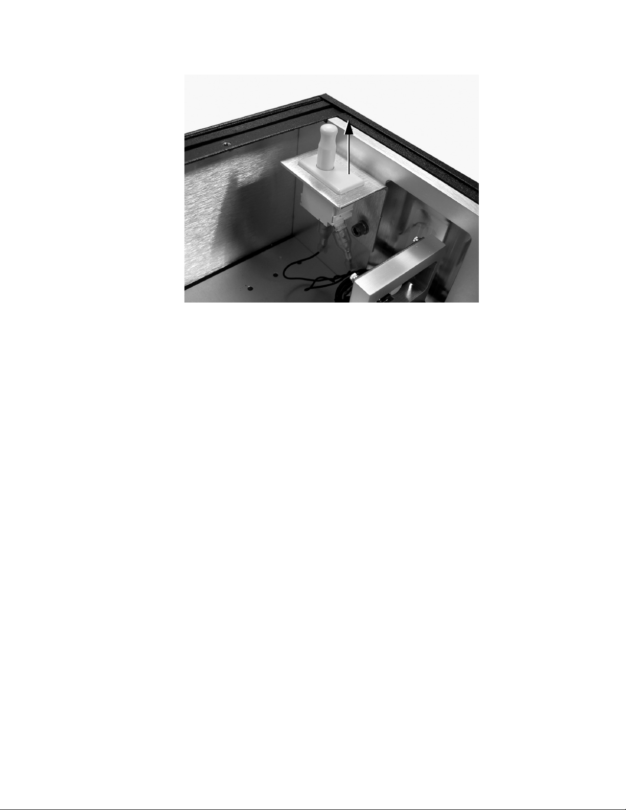
Pull up to
defeat interlock
Figure 7-1. Cover Interlock
Optical Alignment
Front Bezel, Side Wall, and Internal Baffle Removal
Using an IR Viewer
3. Pull the cover interlocks upward to defeat them (see
Figure 7-1).
4. Clear the fault by cycling the Vitesse and Evolution key
switches.
5. Take appropriate laser safety precautions before reactivating
the laser.
For many of the following alignment procedures, it is convenient
(and in some cases necessary) to remove the outer walls and/or the
internal baffle. Removing these barriers can create a safety hazard
and have an adverse effect on system stability. Replace all covers,
walls, and baffles before returning the system to normal operation.
Using an IR viewer when aligning the beam to an iris or alignment
target can improve the accuracy of the alignment.
7 - 3
Page 58
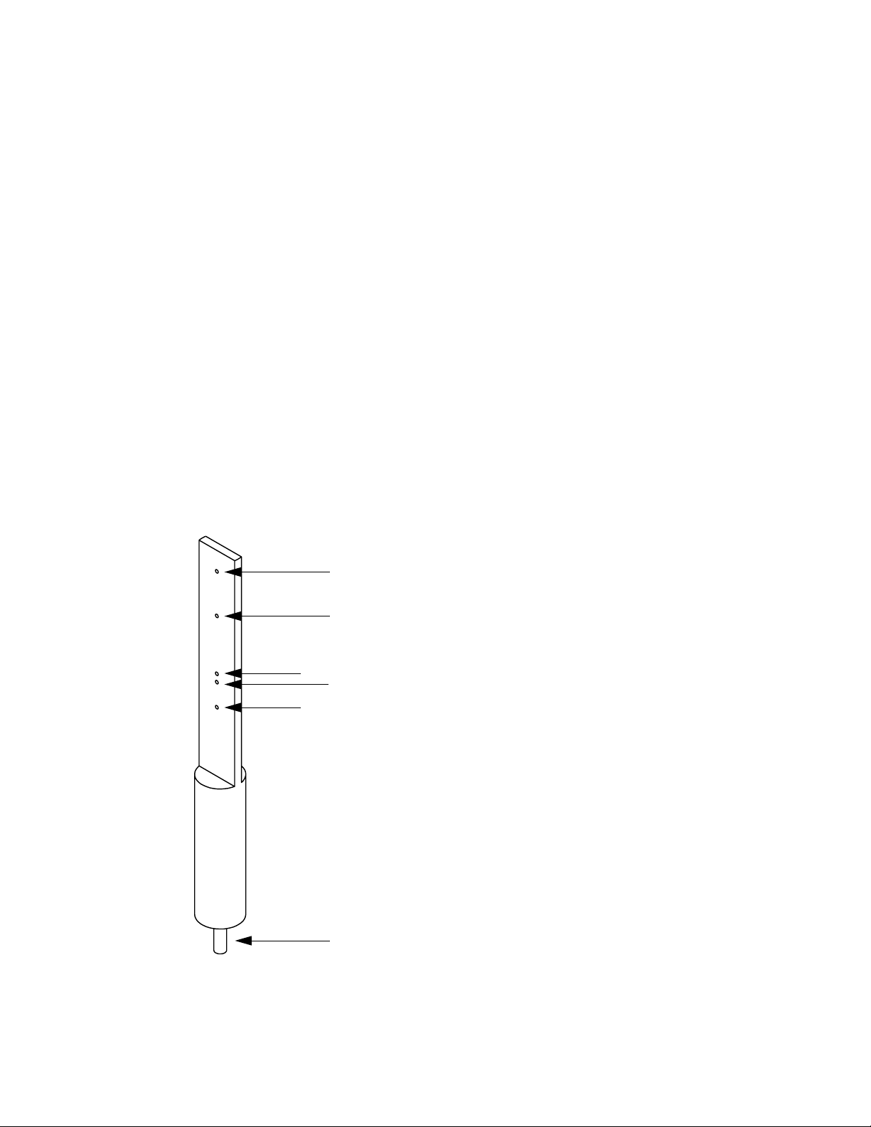
Libra Operator’s Manual
Alignment Apertures
Adjustable Irises
Fixed Alignment Targets
The Libra includes several alignment apertures to maintain system
performance:
Figure 2-3 on page 2-4 shows the location of the adjustable irises in
the regen and compressor.
• RI1 and RI2 are used to maintain regen cavity alignment.
• RI3 and RI4 maintain alignment of the regen output telescope.
• CDI must be installed before use. There is a tapped hole in the
location shown in Figure 2-3. The upper iris is for the
compressor input beam, and the lower iris is for the
compressor output beam.
The system also ships with two alignment targets as pictured in
Figure 7-2. These fit into non-tapped holes in the baseplate, as indicated in Figure 7-3. A1 through A5 all lie on the same line.
4.125” (A4 and A5 compressor input height)
3.592” (A4 and A5 stretcher input height)
2.90” (A4 and A5 compressor output height)
2.80” (A1 and A3 stretcher input height)
2.50” (regen cavity beam height)
post for alignment target holes (see Figure 7-3)
Figure 7-2. Fixed Alignment Target and Associated Beam Heights
7 - 4
Page 59
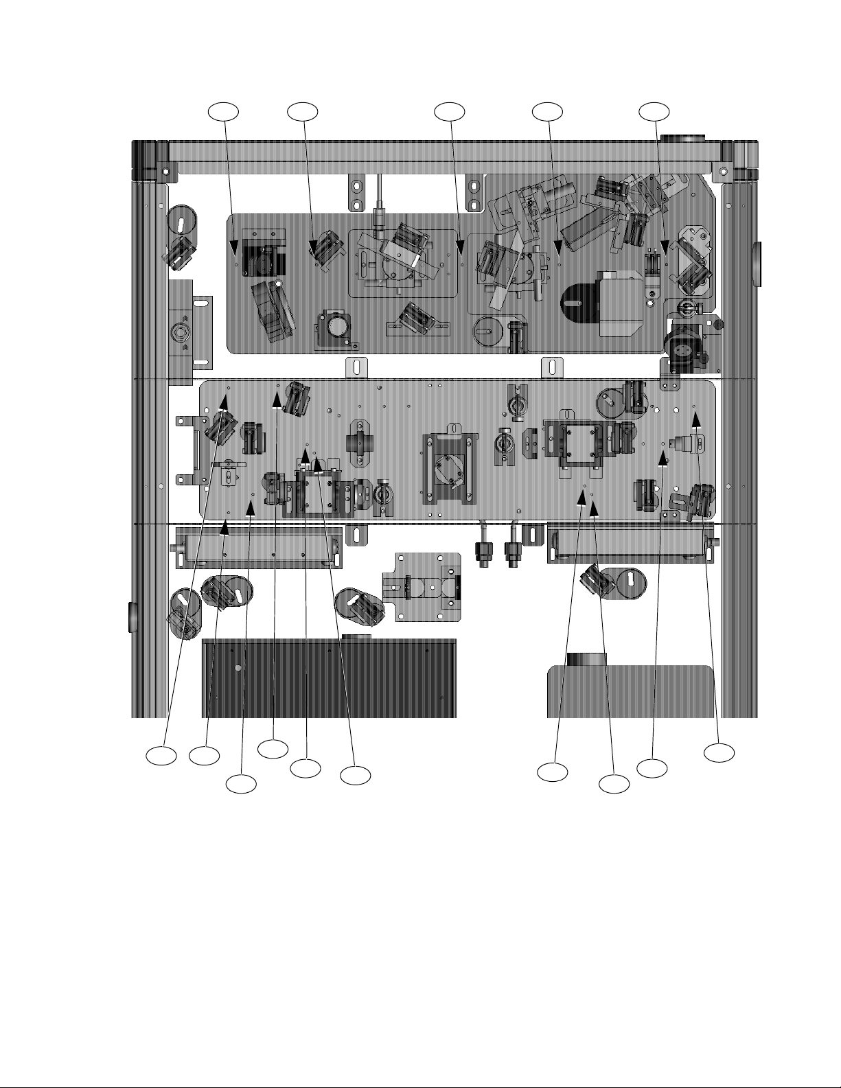
Optical Alignment
A1 A2 A3 A4 A5
RA1
RA7
RA5
RA4
RA3
RA6
RA2
PA1PA2
RA8
Figure 7-3. Fixed Alignment Target Locations and Labels
“Align to A1” means “center the beam on an alignment target installed in the A1 location.”
7 - 5
Page 60
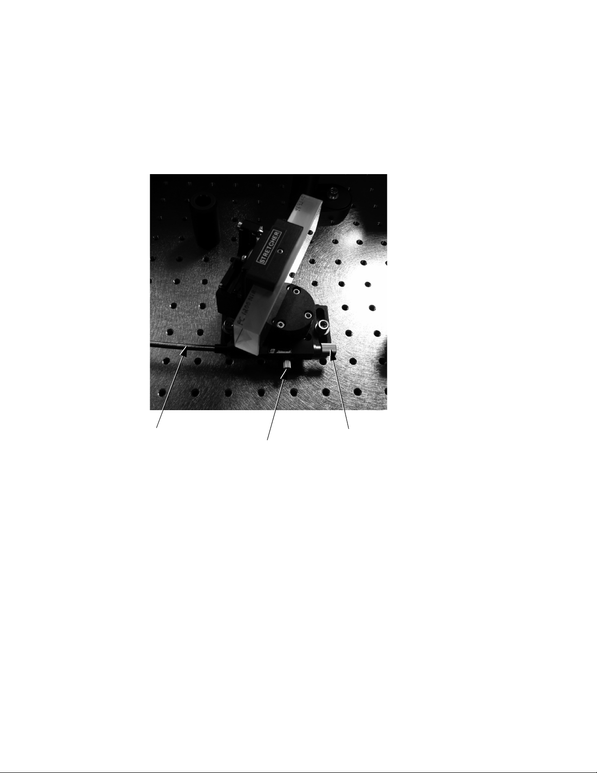
Libra Operator’s Manual
Grating Rotation
The Libra provides external control knobs for fine adjustments of
the grating angles. Each grating rotation stage is equipped with a
locking screw which must be tight for the control knobs to function.
For large angle changes, or if the micrometer has run out of travel,
loosen the locking screw and rotate the mount by hand. See
Figure 7-4.
Grating cable (to external control knob)
Figure 7-4. Grating Mount Adjustments
Retroreflector Alignment
The Libra contains three retroreflector assemblies comprising two
mirrors each: SM5-6, CM2-3, and CM4-5. The procedures below
describe fine adjustments to the control knobs of these optics. Rough
alignment of these assemblies was performed in the factory using an
external apparatus. Contact Coherent Service if a large change has
been made to the retroreflector angles.
Micrometer stop
Locking screw
7 - 6
Page 61
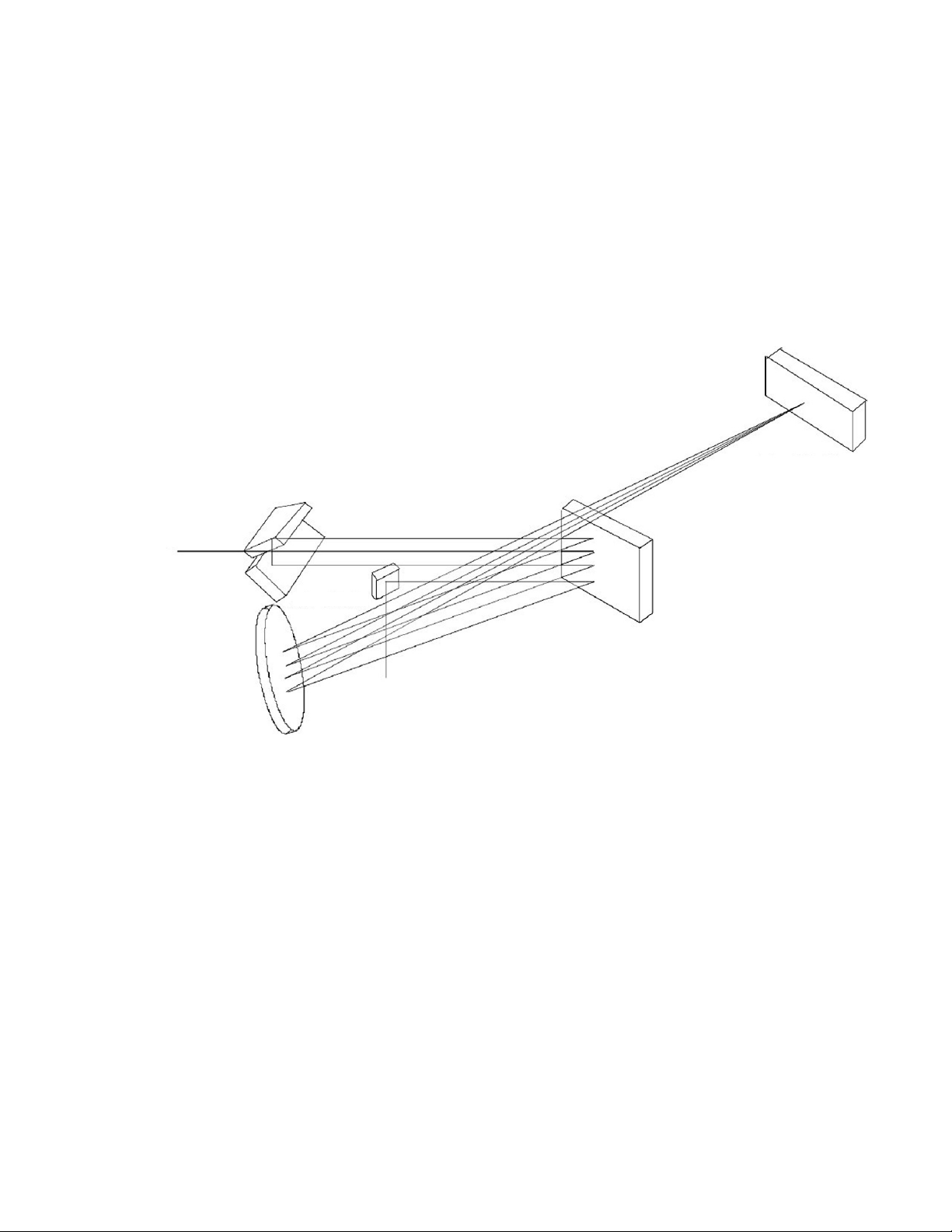
Stretcher Alignment
Optical Alignment
Stretcher Beam Path
SM6
Input
SM5
The path of the seed beam through the stretcher is straightforward
until the beam encounters the stretcher grating. Figure 7-5 shows the
multiple reflections which occur from SG to SM7 in Libra Femto
systems.
SM4
SM7
SG
Output
SM3
Figure 7-5. Optical Path for Two Passes through the Stretcher
in Libra Femto Systems (4 Reflections from the Grating).
In Libra USP Systems, there are Four Total Passes (8 Reflections from the Grating).
From SG the beam is diffracted to SM3. SM3 introduces a vertical
displacement to the beam path, reflecting the beam over the entire
SG assembly to SM4. From SM4 the beam returns to SM3, and then
to SG, where it strikes the grating a second time just below the first
point of incidence. The beam then propagates to the SM5-6
assembly, which is a vertical retroreflector that raises the beam (the
beam strikes the lower mirror first). From SM6 the beam travels
back to the grating, and traverses the SG-SM3-SM4-SM3-SG path
again. There are a total of 4 reflections from the grating, as shown in
Figure 7-6. The 4th reflection is the lowest spot, which allows the
7 - 7
Page 62
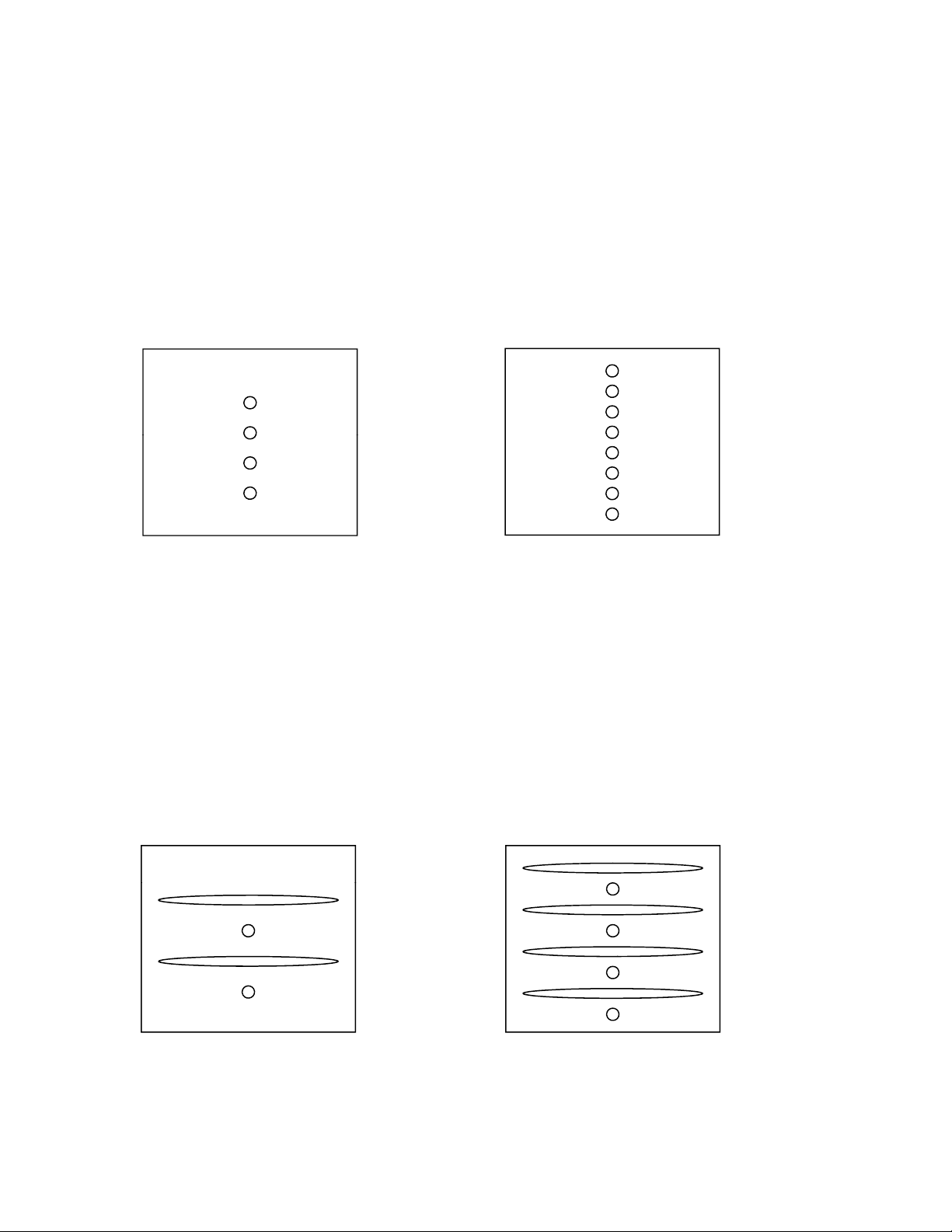
Libra Operator’s Manual
1
5
beam to be intercepted by SM7 and redirected to the SM8-9 periscope. From SM9, the beam travels to SM10 and is reflected into the
regen cavity.
The path of the seed beam from the Vitesse output through the
stretcher is summarized below:
SM1SBS FI SM2SGSM3SM4SM3SG
SM5SM6 SGSM3SM4SM3SGSM7SM8
SM9SM10RGA cavity
7
3
2
4
5
3
1
2
4
6
8
Figure 7-6. Correct Stretcher Grating Beam Pattern and Order of Incidence for a
CW Seed Beam. Left: Femto Systems. Right: USP Systems.
In USP systems, the stretching process is repeated for a total of
8 reflections from the grating.
When the seed laser is modelocked, the proper SG pattern is given
in Figure 7-7. The width of each stripe is directly proportional to the
input bandwidth. At large enough bandwidth the stripes will overfill
SG and SM3.
7
3
1
2
4
3
1
2
4
6
8
Figure 7-7. Correct Stretcher Grating Beam Pattern and Order of Incidence for a
Modelocked Seed Beam. Left: Femto Systems. Right: USP Systems.
7 - 8
Page 63
Optical Alignment
Seed Beam Alignment
1. Disable the Pockels cells and turn off the Evolution.
2. Run the Vitesse in CW mode (disable the Automodelock function and cycle the power). The grating angles given below are
valid only for 800-nm light.
3. Block the Vitesse beam during this step:
Verify that no laser light is present before lowering your head to
read the grating rotation stage angle.
a.) Record the stretcher and compressor grating angles,
given on the rotation stages underneath the gratings.
b.) Install alignment targets at locations A1 and A3.
4. Unblock the Vitesse beam and use SM1 to center the seed
beam on A3.
5. Check the following, performing the given corrective actions
only if necessary. If an adjustment is made, repeat all of the
alignment checks.
Stretcher Grating Yaw Angle Adjustment
a.) No clipping through the Faraday Isolator. Use SM1 and
SBS to center the beam through FI.
b.) Alignment through A1 and A3. Adjust SBS and SM2 to
center the beam on A1 and A3, respectively. Remove the
targets before proceeding.
c.) Stretcher grating shows spots in a vertical line, evenly
distributed on the grating surface, as shown in
Figure 7-6. Using the external control knob, make a
small adjustment to the SG angle to line up the spots as
well as possible.
d.) It is acceptable for the spot locations to deviate slightly
from the pattern shown in Figure 7-6. Do not adjust SG
or SM3-7 unless it is necessary to restore system performance. If complete stretcher realignment must be done,
proceed to the next section.
1. Align the seed beam as described in “Seed Beam Alignment”
on page 7-9.
2. Replace the alignment target at A1.
7 - 9
Page 64
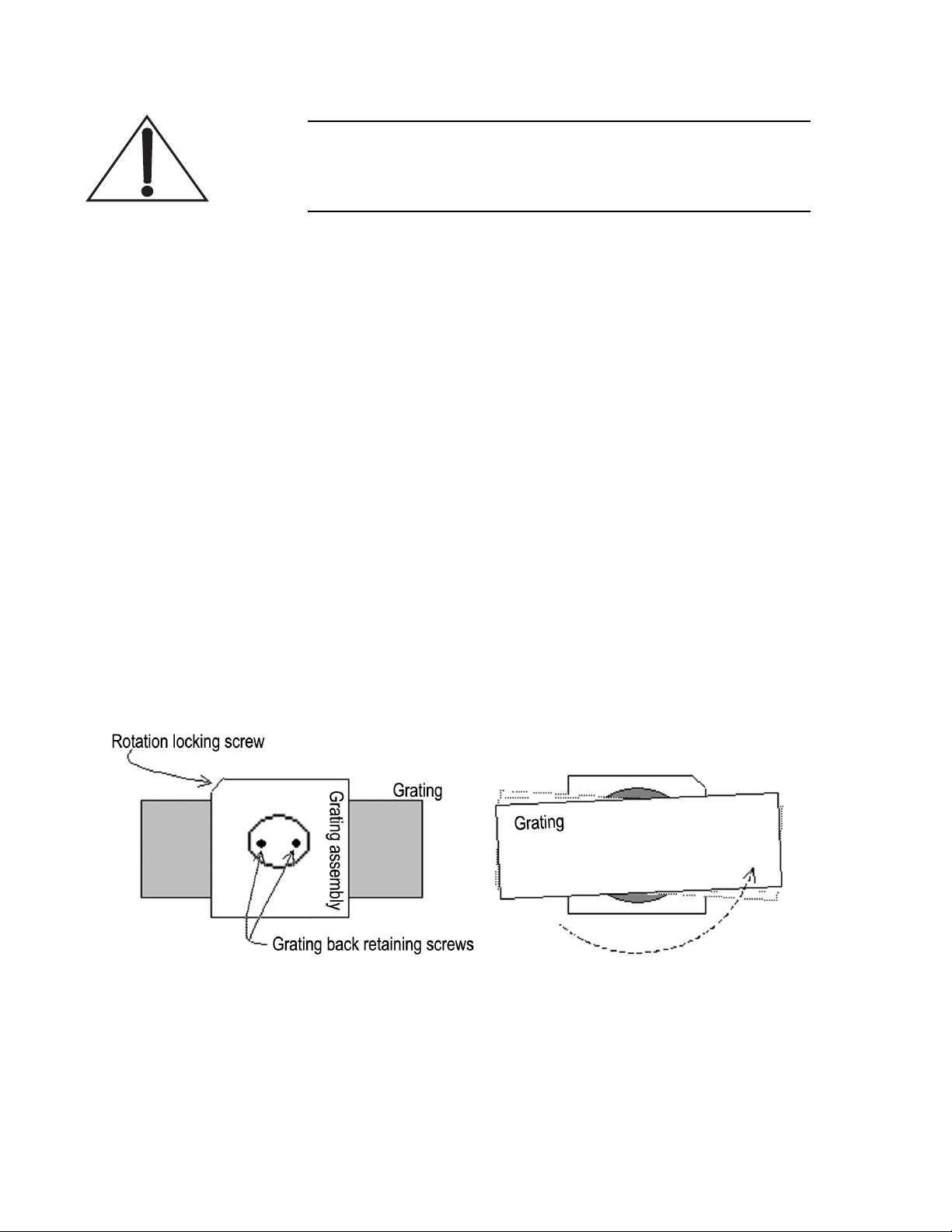
Libra Operator’s Manual
Wear powderless latex or nitrile gloves or finger cots before
touching the grating assembly. The grating surface cannot be
cleaned if contaminated.
3. Loosen the locking screw on the SG rotation stage, and rotate
SG to be roughly perpendicular to the incoming beam. This
sends the zero-order reflection back to A1.
4. Relock the locking screw. Adjust the vertical control on the
grating mount so that the zero-order reflection is at the same
height as A1. It is helpful to rotate the grating (using the
external control knob) to slightly displace the reflection to one
side of the aperture.
5. Loosen the locking screw, and rotate SG so that the first-order
reflection is propagating to A1. Relock the locking screw.
6. If the first-order reflection is not at the same height as A1, the
grating yaw angle must be adjusted. Make sure the incoming
beam is precisely aligned to A1 and A3 before doing this.
Refer to Figure 7-8, and loosen the three screws. Loosen the
“Grating back retaining screws” just enough to enable rotation
of the grating. Rotate SG until the first-order reflection is at the
same height as A1. Retighten the three set screws. When tightening the Grating back retaining screws, alternate between
them to minimize the chance of the grating moving.
Figure 7-8. Grating Yaw Angle Adjustment
7. Iterate steps 3. through 6. until both the zero- and first-order
reflections are at the same height as A1. This may require
several iterations. The last time through, with the grating in the
7 - 10
Page 65

Optical Alignment
first-order position, adjust the vertical control on the grating
mount to precisely align the first-order reflection to the A1
height.
Compressor Grating Yaw Angle Adjustment
SG to SM7 Alignment
If the compressor will also be aligned, it is convenient to perform the
yaw angle adjustment of the compressor grating at this time.
1. The CG rotation angle should already have been recorded (see
“Seed Beam Alignment” on page 7-9).
2. Rotate SG out of the beam path (roughly parallel to the side
wall).
3. Repeat the zero- and first-order adjustments described in
“Stretcher Grating Yaw Angle Adjustment” on page 7-9 with
the compressor grating.
4. Return the CG assembly to its original rotation angle.
1. Rotate SG to be roughly perpendicular to the seed beam.
2. Use the external rotation control knob to align the zero-order
reflection on A1.
Verify that no laser light is present before lowering your head to
read the rotation stage angle.
3. Block the Vitesse beam and record the grating angle.
4. Rotate SG as given below:
• 22
• 60
5. Using the SM3 vertical control, lower the beam until the
reflection from SM3 can be seen on the SG surface, and eventually on A1. Center the reflection on A1 with the SM3 vertical
and horizontal controls.
6. Using the SM3 vertical control only, raise the beam until it
strikes SM4. Temporarily modelock the seed laser and adjust
the SM3 vertical control to light the BWD photodiodes, as
indicated by the LEDs on the front panel of the SDG.
7. Use the SM4 controls to center the reflection from SM4 on A1.
o
clockwise from normal for USP systems
o
counterclockwise from normal for Femto systems
7 - 11
Page 66
Libra Operator’s Manual
8. Using the SM4 vertical control only, lower the beam ~3 mm on
A1. The beam will now strike SM5 when the alignment target
is removed.
The SM4 vertical angle is used to control the spacing between
the spots on the grating surface. Remove the alignment target
at A1 and look at the beam pattern on SG. Use the vertical
control of SM4 to approximate the spacing shown in
Figure 7-6 on page 7-8.
9. Remove A1.
10. Look at the SM4 surface. If two spots are visible, adjust SM6
to overlap them on top of each other.
11. Look at the beam pattern on SG. Repeat all stretcher alignment
steps up to this point if the beam pattern does not match
Figure 7-6 on page 7-8.
12. Adjust the height of the SM7 optic if the beam is not striking
~1 mm from the top edge. Alternatively, make a small adjustment with the SM3 vertical control and then return to step 10.
Stretcher Spatial Chirp Removal
13. Check the beam patterns on SM3 and SG for clipping.
14. Adjust the horizontal and vertical controls of SM7 to roughly
center the beam on SM8.
15. Modelock the Vitesse and verify that the BWD photodiodes
are detecting seed light. Adjust the photodiode position if
necessary.
It is critical that any spatial chirp be removed from the seed
beam before it enters the RGA. Amplification of a spatially
chirped pulse can result in permanent damage to RGA components. Even a small amount of spatial chirp will compromise the
Libra output characteristics.
SM8-9 Periscope The procedure given below monitors the seed beam after it has
passed through the SM8-9 periscope. The periscope interchanges
the horizontal and vertical axes of the beam (and rotates the polar-
7 - 12
Page 67

Optical Alignment
ization by 90o). This is why a vertical adjustment across a horizontal
slit is used to check for horizontal spatial chirp, and a horizontal
adjustment across a vertical slit is used for vertical spatial chirp.
Horizontal Spatial Chirp
1. Install a slit or fully collapsed iris in front of a spectrometer.
For example, cut a slit into a business card and center it over
the spectrometer input.
2. Position the spectrometer on the RGA baseplate to intercept
the seed beam. Adjust SM10 if necessary. Alternatively, install
a routing mirror after SM10 to reflect the beam out of the Libra
to a spectrometer input.
a.) Orient the slit so that it is horizontal. See “SM8-9 Peri-
scope” on page 7-12.
b.) Adjust SM10 to send the beam toward the spectrometer
input.
3. Monitor the seed spectrum while sweeping the beam across the
slit using the SM10 vertical control. Although the amplitude of
the entire spectrum will change, the spectrum must not shift. A
more detailed procedure is given below:
a.) Position the seed beam off-center directly above the slit,
and rescale the spectrometer window.
b.) Sweep the beam across the slit. The spectrum will
temporarily go off-scale in the spectrometer window.
c.) Continue moving the beam until it is below the slit, and
the spectrum again falls into the spectrometer window.
d.) The spectra from steps a. and c. must be identical.
4. Horizontal spatial chirp is removed by changing the distance
between SM3 and SM4. This is conveniently done in the Libra
by adjusting the micrometer on the SM4 mount.
a.) Record the micrometer reading.
b.) Adjust the micrometer a discrete amount in one direc-
tion, and check for spatial chirp again as described in
step 3.
c.) If the amount of spectral shift decreases, adjust the
micrometer again in the same direction. If the shift
increases, adjust the micrometer in the opposite direction.
d.) Iterate steps a. through c. until no spectral shift is present.
7 - 13
Page 68

Libra Operator’s Manual
Vertical Spatial Chirp 1. Position the spectrometer and/or slit so that the slit is oriented
vertically. See “SM8-9 Periscope” on page 7-12.
2. Sweep the seed beam across the slit as described above, but
using the SM10 horizontal control.
3. To remove vertical spatial chirp, SM5 and SM6 must both be
adjusted:
a.) Note the peak intensity of the spectrum.
b.) Make a small discrete adjustment with the SM5 vertical
control (lower mirror of the retroreflector).
c.) Use the SM6 vertical control (upper mirror) to restore the
original peak intensity on the spectrometer.
d.) Check for vertical spatial chirp again by sweeping with
the routing mirror. If the chirp has decreased, return to
step b. and adjust SM5 again in the same direction. If the
chirp has increased, return to step b. and adjust SM5 in
the opposite direction.
RGA Input Alignment
RGA Alignment
RGA Beam Path
e.) Iterate steps a. through d. until no spectral shift is present.
1. Adjust SM9 (and SM7 if necessary) so that the beam is straight
and level between SM9 and SM10.
2. Adjust SM10 so that the reflection from RTS is centered on
RI1.
Refer to Section Six: Maintenance and Troubleshooting before
performing these procedures. Complete realignment should only be
done when other troubleshooting methods do not restore system
performance. Read this entire section before beginning. Contact
Coherent Service with any questions.
The RGA cavity employs a Z-fold configuration. The beam path is
summarized below:
PC1 RWPRI1 RM2RTS
RM1
RM3RP RI2 PC2 RM4
RM2 and RM3 are dichroic “pump-through” mirrors which reflect
the IR cavity beam but transmit the green pump beam.
RP transmits or reflects the beam depending on its polarization (See
“Seeded Operation” on page 7-26).
7 - 14
Page 69

Optical Alignment
RWP resides next to PC1, but can be moved to the PC2 location
during free-running alignment procedures (described below).
During normal operation, leave RI1, RI2, RI3, and RI4 fully open.
RGA Alignment Apertures
Cavity Alignment with Seed Beam
Refer to Figure 7-3 on page 7-5 for the location of the alignment
target holes.
RA1 and RA2 define the beam path between RM1 and RM2.
RA3 and RA4 define the beam path between RM2 and RM3
(through the Ti:S crystal).
RA5 and RA6 define the path between RM3 and RM4.
RA7 defines the angle of the polarizer (path from RP to RM5).
RA8 defines the angle of RM5 (path from RM5 to RM6).
1. Disable the Pockels cells and turn off the Evolution.
2. Verify that the seed beam is precisely aligned to A1, then
remove the alignment target.
3. Place a small mark on the RWP teflon mount to indicate the
waveplate setting.
4. Remove RWP and RM1 from their mounts.
5. Install alignment targets at RA1 and RA2.
6. Install a routing mirror to intercept the seed beam between
SBS and SM2, and route the beam into the RGA cavity
through the back of RM1. Position the mirror so that the beam
is roughly aligned to RA1 and RA2.
7. Install an adjustable iris to be centered on the beam between
SM1 and SBS.
Note: At various points in this procedure, it may be helpful to
partially close the iris. A smaller beam can increase the precision
of the cavity alignment.
8. Use SBS and the routing mirror to precisely center the beam
on RA1 and RA2, respectively.
9. PC1 alignment:
7 - 15
Page 70
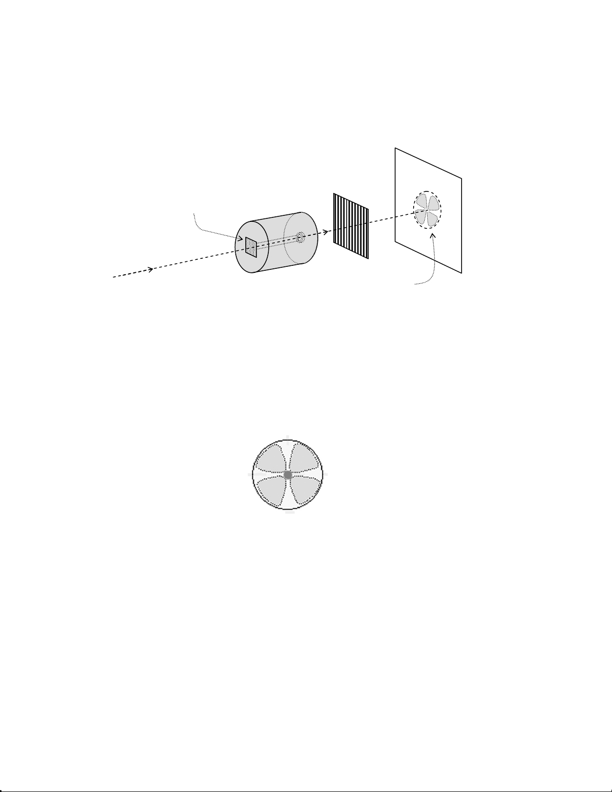
Libra Operator’s Manual
Semi-transparent
tape
a.) Refer to Figure 7-9. Place a piece of frosted tape over the
PC input aperture. Setup a polarizer after the PC, and
view the transmitted beam on a card.
C
a
r
d
o
r
s
c
r
e
e
n
S - Polarizer
l
l
e
c
s
l
e
k
c
o
P
Scatter
pattern
Figure 7-9. Pockels Cell Alignment
b.) Translate and adjust the angle of the PC to center both the
beam and the 4-lobe clover pattern through the PC, as
shown in Figure 7-10.
Figure 7-10. Correct, Symmetric Pattern of the Seed Beam Scattered Through
a Pockels Cell and Polarizer
c.) The PCs are adjusted by means of the 4 adjustment
screws shown in Figure 7-11. The top pair of screws
allows horizontal adjustment. Adjusting either screw
changes the PC angle, while adjusting both screws the
same amount (in the same direction) translates the entire
cell. Vertical adjustment is accomplished the same way,
using the bottom pair of screws.
d.) Horizontal translation of the PCs may also be accom-
plished by sliding the entire mount. Keep the mount
pressed against the dowel pins if it is necessary to do this.
7 - 16
Page 71
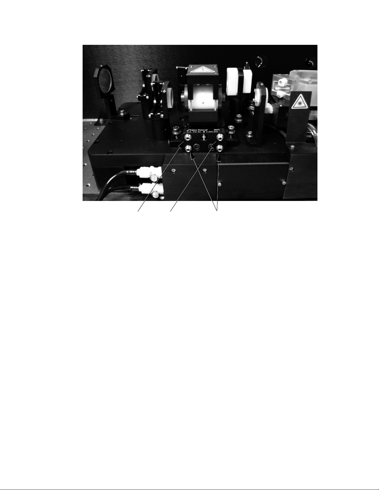
Optical Alignment
Horizontal Adjustment Vertical Adjustment
Figure 7-11. Pockels Cell Adjustment Screws
e.) After the PC has been aligned, remove the tape, polar-
izer, and business card.
10. Recheck the alignment to RA2. Iterate steps 9 and 10 until the
beam is aligned to RA1 and RA2, and the scatter pattern
matches Figure 7-10.
11. Position RI1 to symmetrically collapse around the beam.
12. Use RM2 to center the beam on RA4. If it is difficult to see the
beam:
a.) Install RA1, partially close RI1, and/or partially close the
iris installed next to SM1 (step 7. above).
b.) Install RWP, and rotate the waveplate for maximum
brightness of the seed beam on RA4.
13. Use RM3 to center the beam on RA6.
14. Repeat the Pockels cell alignment procedure given in step 9.
for PC2.
15. Iterate steps 13 and 14 until the beam is aligned to RA6, and
the scatter pattern matches Figure 7-10.
7 - 17
Page 72

Libra Operator’s Manual
16. Check that RP is centered on the beam, and translate the mount
if necessary. If RP must be translated, return to step 13.
17. Position RI2 to collapse symmetrically around the beam.
18. Align the retro-reflection from RM4 to overlap with the
forward beam.
a.) Close RI2 to approximately 3 mm to observe diffraction
rings around the retro-reflection for easier alignment.
b.) Follow the retro-reflection back through the cavity. Use
RM4 to center the retro-reflection on A5, A2, and/or A1
as necessary.
c.) Use RM4 to center the retro-reflection on the iris
installed next to SM1 (step 7. above).
19. Replace RM1 in its mount. A strong reflection from the back
side of RM1 will be visible on the iris installed next to SM1.
20. Use the RM1 controls to center the back-reflection on the iris
installed next to SM1.
Pump Beam Alignment
Pump Beam Alignment and Collimation
The procedures below involve large changes to the pump beam
pointing. The pump power must be held at a low level
(~100 mW). Do not allow a high-power pump beam to be steered
off of the Ti:S crystal surface. In addition to the danger posed by
specular reflections of the pump beam, metal from the crystal
mount may be ablated and contaminate an optical surface.
1. Install a beam block in front of PM4.
2. Set the Evolution current to just above lasing threshold. Turn
on the Evolution.
3. Note the location of the pump beam on RTS (close to center by
default).
4. Adjust PM1 to center the beam through PL1 and PL2.
5. Compare the beam size just after PL2 and just in front of PL3.
Translate PL2 within its track if necessary to collimate the
beam.
7 - 18
Page 73

Optical Alignment
6. Adjust PM2 to restore the original location of the pump beam
on RTS.
7. Iterate steps 2. through 5. until the beam is centered on PL1
and PL2, collimated, and striking near the center of the crystal
face.
Lasing Initiation 1. If not already done, inscribe a mark on top of the teflon RWP
holder to note its position. Remove RWP (remove the teflon
cylinder from its mount).
2. Use PM2 and PM3 to align the pump beam through alignment
targets RA2 and RA3. Verify that the beam is centered through
PL3.
3. Verify that the pump beam is close to center on RTS. Adjust
PM3 if necessary.
4. Increase the Evolution to normal operating power.
5. Look at RM4 with an IR viewer. Rock the RM4 mount while
looking for a lasing flash.
Free-Running Optimization
a.) If no flash is seen, look at the back reflection from RM1
on the iris installed next to SM1 (see “Cavity Alignment
with Seed Beam” on page 7-15). Use the back reflection
as an index for the position of RM1. Systematically
search for lasing by making a small adjustment to RM1,
and then rocking RM4.
b.) If lasing cannot be achieved, repeat the “Cavity Align-
ment with Seed Beam” on page 7-15 procedure.
6. When lasing occurs, block the seed beam from entering the
RGA cavity.
7. Optimize the brightness of the flash by adjusting RM1 and
RM4. Optimize each mirror individually - beam walking is
described below.
1. Disable PC1 and PC2. Block the seed beam from entering the
RGA cavity.
Before it is expanded, the RGA output beam contains a large
amount of energy in a small beam. Do not place anything in the
beam path between RP, RM5, and RI3.
7 - 19
Page 74
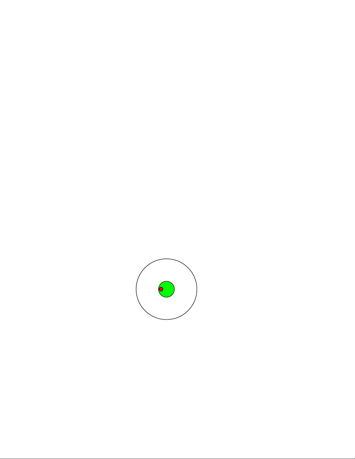
Libra Operator’s Manual
2. Verify that the RGA output beam is propagating roughly
between RM5 and RM6. Do not adjust RM5 at this time.
3. Install a power meter in front of RM6 or in front of RM8.
4. Block RGA lasing by leaning a card against RM1. Install RWP
in the PC2 location. Unblock the beam, and rotate RWP for
maximum power.
5. Adjust the following optics for maximum power:
a.) RM1
b.) RM4
c.) PM3
d.) PM4 (unblock the pump beam retroreflection while this
is being done)
e.) RWP rotation
Beam Walking The angle between the pump and IR beams is also important (the
beams are not collinear outside of the crystal because the angle of
refraction at the crystal surface is a function of wavelength). As
shown in Figure 7-12, the angle is correct when the IR beam is
displaced ~3 mm from the center of the green beam on RM2 and
RM3. This also corresponds to the highest RGA power output.
Figure 7-12. Correct Beam Pattern as Viewed on RM2 and RM3
The correct angle is achieved by walking the pump beam relative to
the IR beam. It is also possible to walk the IR beam, but any significant change to the IR alignment will misalign the beam relative to
the PCs.
7 - 20
Page 75

Optical Alignment
Walking is a two-dimensional optimization where a discrete change
is made to one mirror, and the power is then optimized using a
second mirror. If the power improves, make another change to the
first mirror in the same direction. If the power decreases, adjust the
first mirror in the opposite direction.
1. Walk the pump beam using PM2 and PM3 to obtain the pattern
shown in Figure 7-12. When the beam pattern is close to
Figure 7-12, walk with PM2 and PM3 for maximum power.
Use PM2 to change the location of the pump beam on RM3,
and use PM3 to optimize power.
2. Walk the IR beam using RM1 and RM4. Make small changes
only.
The IR beam position can be monitored using alignment targets RA1
and RA6. A small amount of light leaks through each end mirror and
can be seen on the targets with an IR viewer. It is not necessary to
precisely center the RGA cavity beam through the target, but the
targets provide a convenient reference.
Free-Running Pockels Cell Alignment
The PCs were initially aligned to the seed beam passing through the
alignment targets. Keeping the RGA cavity beam close to RA1 and
RA6 prevents significant misalignment through the PCs.
3. To move the beam on RA1, walk with RM2 and RM1, i.e., use
RM2 to change the location on the target and use RM1 to optimize power. To move the beam on RA6, walk with RM3 and
RM4. If the power drops, walk with RM1 and RM4 for power.
4. Iterate the above steps as necessary to optimize free-running
power and beam profile.
1. Block RGA lasing by leaning a card against RM1. Remove
RWP, and unblock the beam.
2. Position a spectrometer in front or in place of the power meter
to monitor the RGA leakage spectrum (with the RWP removed
most of the RGA energy is held within the cavity; however,
there is a small amount of leakage which may be monitored).
Pockels cell misalignment causes modulation in the spectrum.
Figure 7-13 shows examples of good and bad PC alignment.
3. If necessary, make small changes to the PC1 adjustment
screws to remove modulation from the spectrum.
4. Make small changes to the PC2 adjustment screws to minimize
the amplitude of the entire spectrum, i.e., to minimize the
amount of leakage out of the RGA.
7 - 21
Page 76
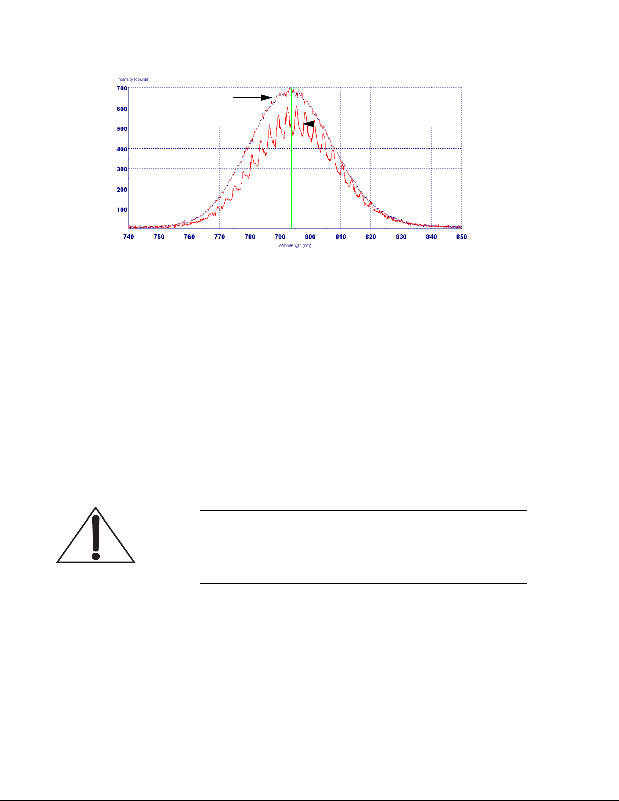
Libra Operator’s Manual
PC1 Well-Aligned
Figure 7-13. Spectral Modulation Due to Pockels Cell Misalignment
(This Signal Is Not From the Regen Photodiode)
PC1 Misaligned
5. Block RGA lasing by leaning a card against RM1. Replace
RWP, and unblock the beam. Rotate RWP for maximum
power.
LBO Temperature Optimization
1. Note the free-running RGA power, the pump power, and the
Evolution LBO temperature.
2. Raise the LBO temperature by 0.3oC. After allowing a few
minutes for temperature stabilization, measure the RGA and
pump power again. If RGA power has increased, raise another
0.3oC. Continue until RGA power begins to drop.
If the pump power decreases suddenly, turn off the Evolution
and reset the LBO temperature to a previous value. If the
doubling efficiency is too low the Evolution can sustain permanent damage.
3. If RGA power drops from the start, lower the temperature in
0.3oC increments.
4. If RGA power increases and pump power does not change
much, leave the LBO temperature at the new value. If RGA
power increases by 0.1-0.2 W but pump power drops by
>1.0 W, return LBO temperature to previous set point.
7 - 22
Page 77

Optical Alignment
5. Confirm that the LBO rollover point is >1.0oC away. Increase
the LBO temperature by 0.5oC increments and verify that the
pump power does not decrease by a large amount.
Concluding Steps 1. Iterate among the free-running adjustments above to optimize
output power and beam profile.
2. It is acceptable to increase the Evolution current by 0.1 or
0.2 A, particularly if the Evolution has aged by a significant
number of hours.
3. Position RI1 and RI2 to collapse symmetrically around the
intracavity beam.
4. Inscribe a mark on the teflon RWP mount to indicate
free-running position.
5. Record the pump current, pump power, and free-running
power for future reference. Note the location of the beam on
RA1 and RA6.
Unseeded or “Q-Switched” Operation
1. Block the seed beam from entering the RGA cavity.
2. Block RGA lasing by leaning a card against RM1. Move RWP
to the PC1 location. Unblock the beam.
3. Set RWP to the correct rotation angle:
a.) If a mark was inscribed during seeded operation, reset
the RWP to the mark.
b.) Otherwise, rotate RWP until lasing stops.
c.) Rotate RWP a little farther until lasing just begins.
d.) Rotate RWP back the other direction until lasing just
begins.
e.) Set RWP rotation at the midpoint between the angles in
steps c. and d.
4. Verify that SDG Delay 1 is >100 ns. Enable PC1.
5. Monitor the unseeded pulse train on an oscilloscope by
looking at the “Regen Buildup” signal from the Libra rear
panel. Enable SDG Delay 3 and use this as the oscilloscope
trigger. It may be necessary to adjust Delay 3 or the oscilloscope X-scale to view the unseeded pulse train. A typical
unseeded pulse train is shown in Figure 7-14.
7 - 23
Page 78
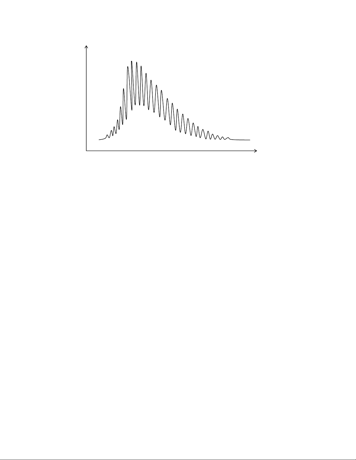
Libra Operator’s Manual
RGA Photodiode Signal
(Regen Photodiode Signal Viewed On an Oscilloscope)
Time
Figure 7-14. RGA Unseeded Pulse Train
RGA Output Telescope
6. Adjust pot R31 in the SDG control box to optimize the coarse
timing of the PCs relative to the Evolution Q-switch.
Figure 7-15 shows examples of good and bad coarse timing.
This adjustment must be repeated if the repetition rate of the
pump laser is changed, or if substantial change has been made
to the Evolution current.
7. If SDG pot R71 is not set correctly the pulse train will flicker.
Adjust pot R71 to be 1-2 full turns away from the onset of
flickering.
8. Enable SDG Delay 2. Adjust Delay 2 to maximize power. A
typical unseeded, cavity-dumped pulse train is shown in
Figure 7-16. Delay 2 is ~150 ns later than Delay 1. Record the
delay values and the unseeded power, which should generally
be equal to free-running power.
RM5 and RM6 are curved mirrors which expand (RM5, convex
mirror) and then collimate (RM6, concave mirror) the RGA output
beam. The position on these optics, the angles of incidence, and the
distance between the optics all affect the propagation of the beam.
Misalignment of these optics will cause the beam to lose collimation.
7 - 24
Page 79
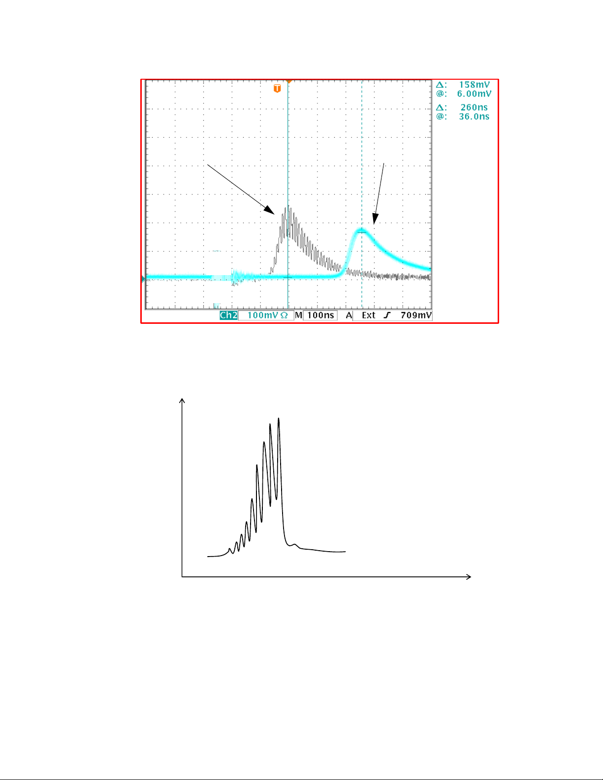
Optical Alignment
Coarse Timing
Set Correctly
Figure 7-15. SDG Coarse Timing Adjustment
Coarse Timing
Not Optimized
RGA Photodiode Signal
Time
Figure 7-16. RGA Unseeded, Cavity-Dumped Pulse Train
These mirrors are set in the factory and should not be moved. RI3
and RI4 are provided for alignment:
1. Use RM5 to center the beam on RI3.
7 - 25
Page 80

Libra Operator’s Manual
2. Use RM6 to center the beam on RI4.
3. If the Libra output beam is not collimated, contact Coherent
Service.
Seeded Operation
The repetition rate of the seed laser far exceeds the rep rate of the
amplifier. Most seed pulses are not amplified. Rather, the Libra
controls the injection and ejection of pulses by manipulating their
polarization, as described below:
• The seed pulses initially have S (vertical) polarization.
• The crystal (RTS) and the polarizer (RP), reflect S-polarized
light but transmit P-polarized light.
• RWP is a quarter-wave plate. However, the pulses pass
through RWP, reflect from an end mirror, and pass through
RWP again. This double-pass rotates the polarization by
90 degrees (from S to P or vice-versa).
• When no voltage is applied to a Pockels cell, it has no effect on
the polarization. When the correct voltage is applied, the PC
behaves as a quarter-wave plate. Again, the cavity configuration results in a double-pass, for a total rotation of 90 degrees.
When both PCs are deactivated, little to no amplification occurs, as
described below:
1. Seed pulses (S polarization) reflect from the crystal face to
RM2 and into the RGA cavity.
2. Each pulse double-passes RWP to become P-polarized.
3. Pulse executes one round-trip through the cavity. Upon
double-passing RWP again, the polarization is rotated back
to S.
4. Pulse reflects from the Brewster window (or crystal surface)
out of the cavity.
Amplification occurs as follows:
1. A seed pulse (S polarization) reflects from the crystal face to
RM2 and into the RGA cavity.
2. Pulse double-passes RWP to become P-polarized.
3. After the pulse leaves RWP, voltage is applied to PC1.
Double-passing PC1 and RWP now results in no net change to
the polarization. The pulse remains P-polarized for multiple
7 - 26
Page 81

Optical Alignment
round-trips, during which it is amplified. All other seed pulses
remain S-polarized and reflect from the cavity before passing
through the Ti:S crystal.
4. After the appropriate number of round-trips (~15), voltage is
applied to PC2. PC2 now rotates the amplified pulse back to
S-polarization. The pulse reflects from the RP surface toward
RM5.
Timing Diagram
RGA Seed Input Alignment
Efficient amplification thus depends on precise control of the timing
of the pump pulse, seed pulses, and Pockels cells. Figure 7-17
provides a summary.
1. Disable PC1 and PC2. Turn off the Evolution.
2. Adjust SM9 and SM10 to center the seed beam on RI1 and
RI2, respectively. Partially close RI1 to aid in alignment to
RI2.
3. Turn on the Evolution, and allow a few minutes for temperature stabilization.
Seeding the RGA cavity with insufficient bandwidth will cause
permanent optical damage.
4. Verify that the seed bandwidth meets Libra requirements.
Refer to the installation report. Contact Coherent Service for
additional information.
5. Enable PC1, and look at the pulse train as described in
“Unseeded or “Q-Switched” Operation” on page 7-23. It may
be necessary to adjust Delay 3 or the oscilloscope X-scale to
view the seeded pulse train.
6. Adjust Delay 1 for a clean pulse train, showing strong main
peaks with minimal secondary peaks.
7. Rotate RWP for a clean pulse train.
Do not block any part of the stretcher beam path (particularly
between SM3 and SM4) while the RGA is running seeded.
7 - 27
Page 82
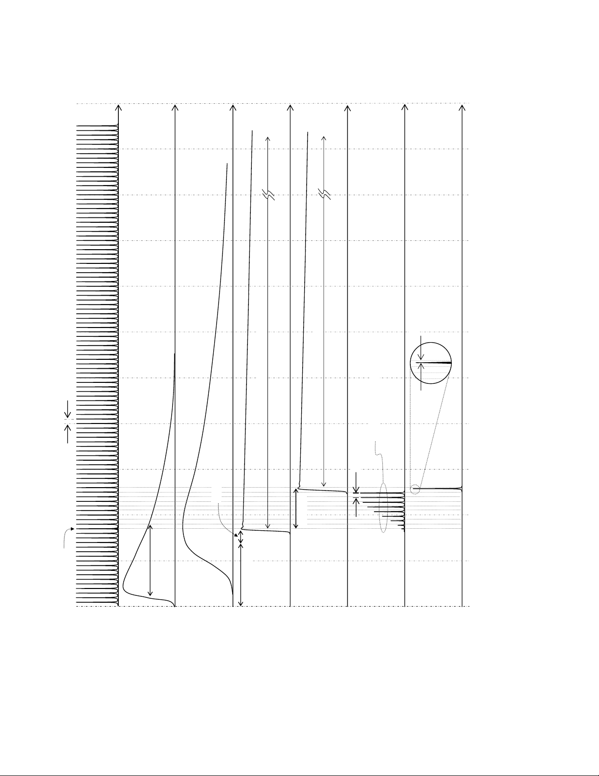
Libra Operator’s Manual
Time
Time
Time
sec
μ
Time
sec
μ
~1.6
Time
Time
Time
[nsec]
0
0
1
1
0
0
0
1
0
0
9
0
0
8
0
0
7
0
0
~3 ns
6
~1.6
~13 ns
~8 to 10 round trips
~10 ns
ns
0
0
4
~
~150 ns
s
n
laser
0
~4
laser
Pump
Injected pulse
Seed
Delay 1
RGA
cavity
Coarse delay
gain
Delay 2
~2-3 ns
trigger
Delay 1
~2-3 ns
trigger
Delay 2
RGA
build-up
RGA
output
0
0
5
0
0
4
0
0
3
0
0
2
0
0
1
0
Pump
trigger
Figure 7-17. Amplification Timing Diagram
7 - 28
Page 83
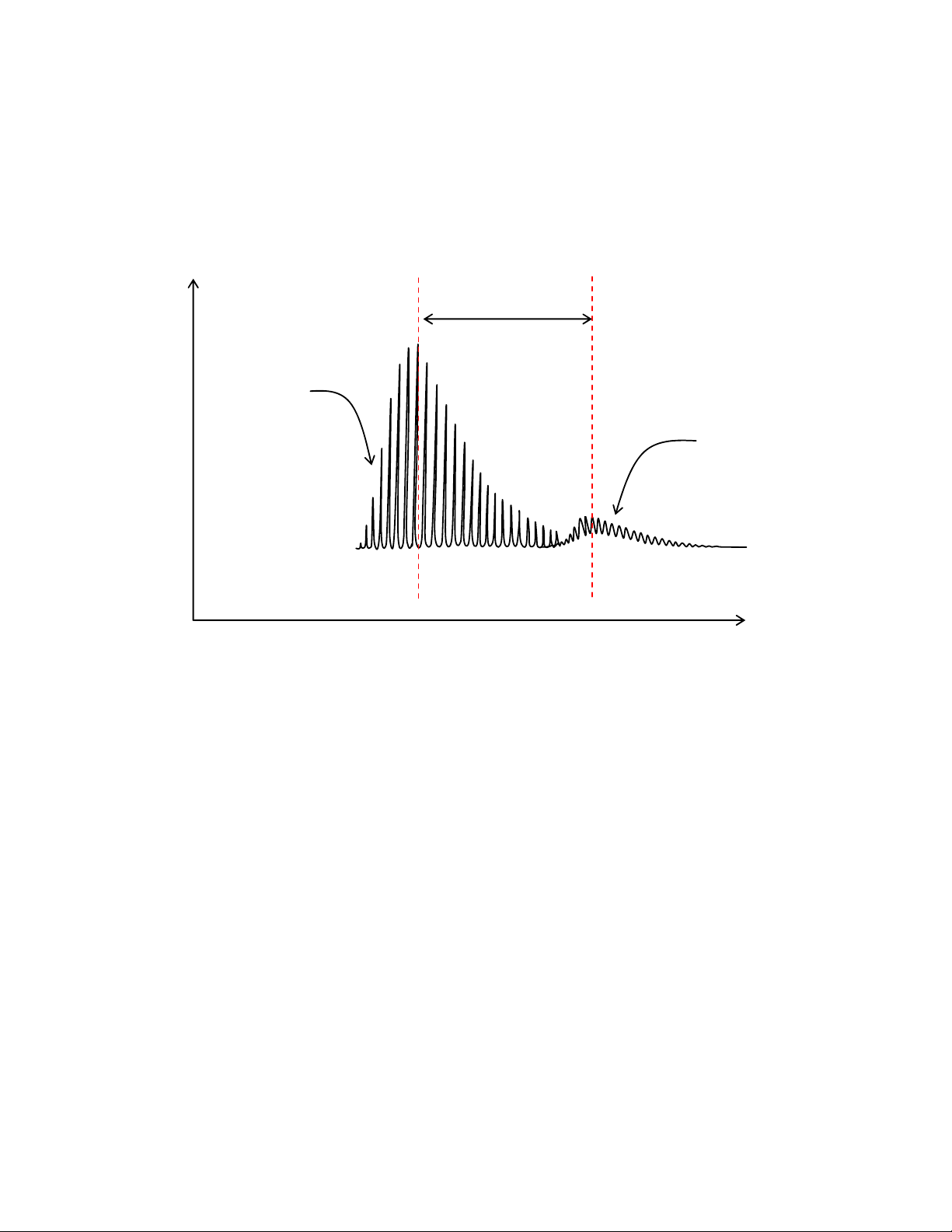
Seeded RGA
build-up
Optical Alignment
8. Walk the seed beam with SM9 and SM10 to maximize
Build-Up Time Reduction (BUTR), i.e., to move the seeded
pulse train as early in time as possible. BUTR is the difference
(in nanoseconds) between the peak of the unseeded pulse train
and the peak of the seeded pulse train, as shown in Figure 7-18.
Build-Up
Time Reduction
Unseeded RGA
build-up
RGA Photodiode Signal
Figure 7-18. Typical Build-up Reduction Time in a Seeded RGA Cavity
Contrast Ratio
Time
(Regen Photodiode Signal Viewed On an Oscilloscope)
9. Iterate steps 6. through 8. to optimize the pulse train.
10. Adjust Delay 2 to optimize output power.
11. Record the power and PC delay values for seeded operation.
1. Couple the Libra output into a photodiode and oscilloscope.
For example, place a beam block outside the output port and
position the photodiode to detect scatter from the block.
Typical scope settings are given below:
• X-scale: 10 ns/div
• Y-scale: 200 mV/div
• Trigger coupling 1 MOhm
• Trigger source SDG Delay 3
7 - 29
Page 84
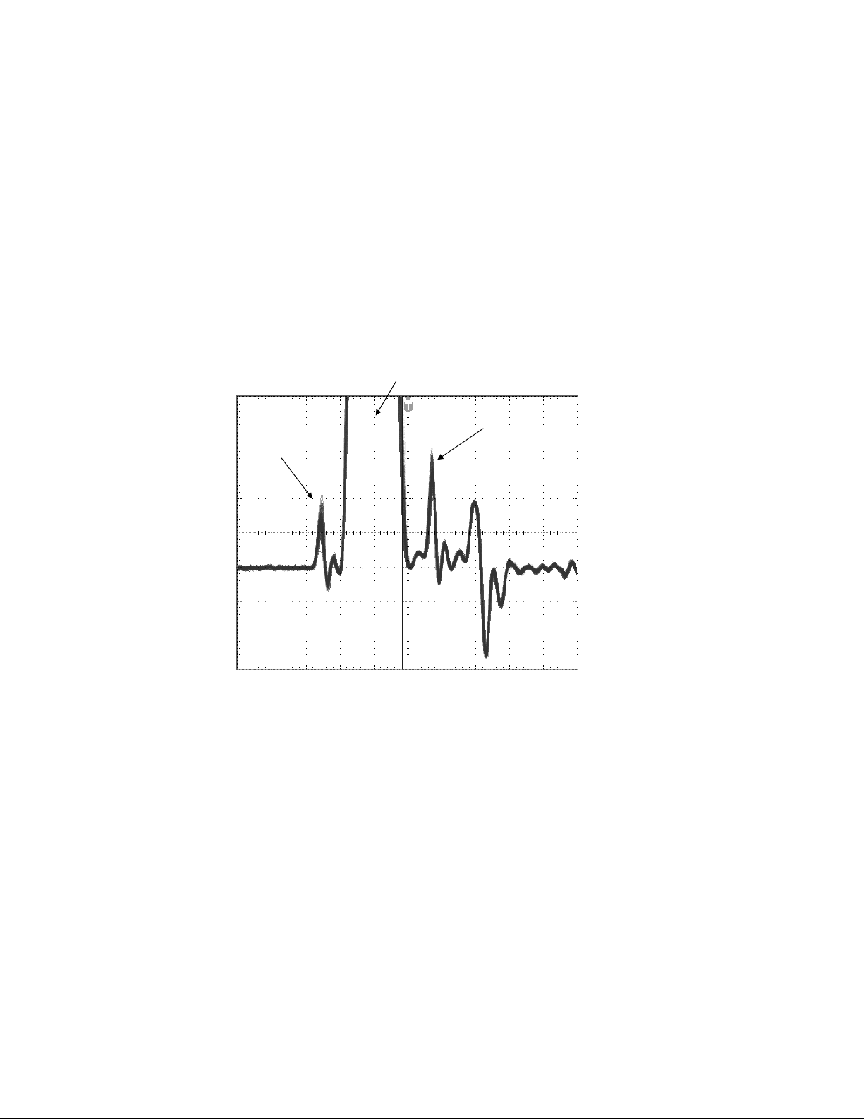
Libra Operator’s Manual
2. Insert neutral density filters with a total factor of ~500 in front
of the photodiode, and position the photodiode so that the main
pulse amplitude is approximately 1 V on the scope. Make sure
the filter densities have been measured at the laser center
wavelength.
3. Remove the filters. The main pulse will go off-scale on the
scope. It can be difficult to resolve the pre- and post- pulses
from the photodiode ringing. Figure 7-19 gives examples of
strong pre- and post-pulses, i.e. a misaligned system. Also, the
pre- and post- pulses show significantly more amplitude jitter
than the ringing.
main pulse (off-scale)
post-pulse
pre-pulse
Figure 7-19. Pre- and Post-Pulses Observed During a Contrast Ratio Measurement
(External Photodiode Monitoring Libra Output, Viewed On an Oscilloscope)
4. Iterate among the following to minimize the pre- and postpulses:
a.) SDG delay timing (Delay 1 and Delay 2)
b.) RWP rotation angle (small changes only)
c.) Pockels cell voltages (refer to “Pockels Cell High
Voltage Settings” on page 7-31)
d.) Pockels cell horizontal and vertical angles (small
changes only, see Figure 7-11 on page 7-17)
5. Record the amplitude of the pre- and post-pulses.
7 - 30
Page 85
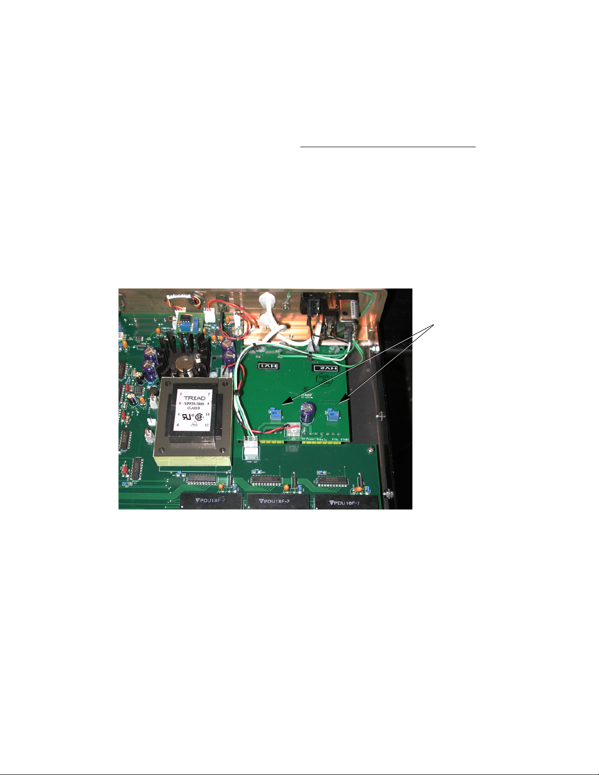
Optical Alignment
6. Replace the neutral density filters, and record the total filter
factor (measured at the laser center wavelength).
7. Record the amplitude of the main pulse.
Contrast ratio may be calculated as shown below:
(pre-pulse am plitude)
(pre-pulse am plitude)
(main pulse amplitude) * (total filter factor)
(main pulse amplitude) * (total filter factor)
Pockels Cell High Voltage Settings
The SDG includes two potentiometers, labeled “HV1” and “HV2,”
that control the voltage applied to each PC. Figure 7-20 shows the
location of these in the SDG control box.
HV Adjustment Pots
Figure 7-20. Location of the HV Adjustment Potentiometers Inside the SDG
HV1 Setting 1. Disable PC1 and PC2. Block the seed beam from entering the
RGA.
2. Monitor the leakage from the RGA by looking on a card in
front of SM9, or with an IR viewer on SM8.
3. Enable PC1. Adjust HV1 to minimize leakage.
7 - 31
Page 86

Libra Operator’s Manual
HV2 Setting 4. Fine adjustments to the PC voltage settings are made while
looking at pre- and pulse-pulses (see “Contrast Ratio” on
page 7-29). For coarse adjustment of HV2, look at the seeded
pulse train. Adjust Delay 2 for best power output, and adjust
HV2 for the cleanest ejection of the pulse. The baseline after
the pulse train should be as flat as possible.
7 - 32
Page 87
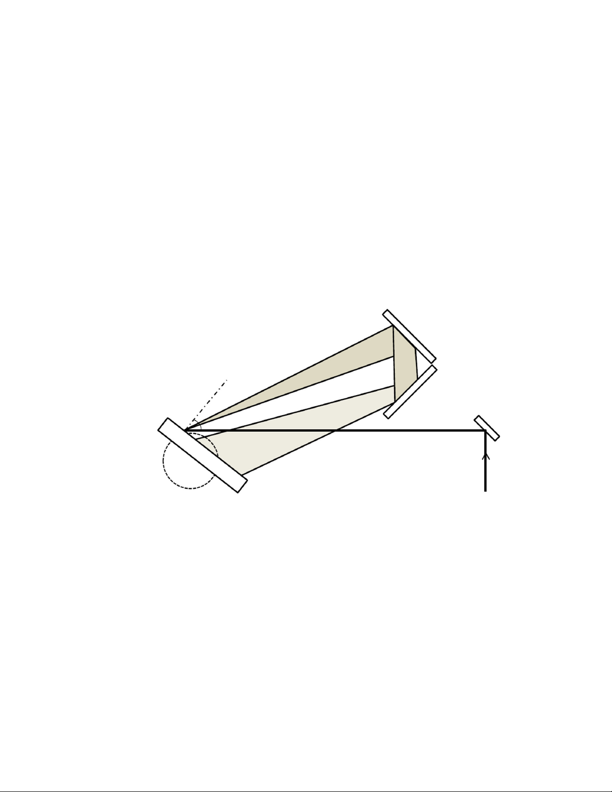
Compressor Alignment
Optical Alignment
Compressor Beam Path
CG
52°
The optics are again labeled in order of beam incidence in Section
Two: Description and Layout. The beam path is summarized as
follows:
CM1CDI CG CM2CM3CG
CM4CM5CG CM3CM2CG CDI output port
CM2 and CM3 form a horizontal retroreflector, and CM4 and CM5
form a vertical retroreflector. CM2 is the mirror closest to the large
stretcher mirror SM7, as shown in Figure 7-21. CM4 is the upper
mirror of the vertical retroreflector.
CM2
Normal
CM3
CM1
Figure 7-21. USP Compressor Beam Path through the Horizontal Retroreflector
Compressor Alignment
Again there are four reflections on the grating surface. The correct
beam pattern on CG is shown in Figure 7-23.
1. Disable the Pockels cells, and block the seed beam from
entering the RGA. Also position a beam block at the Libra
output port.
7 - 33
Page 88
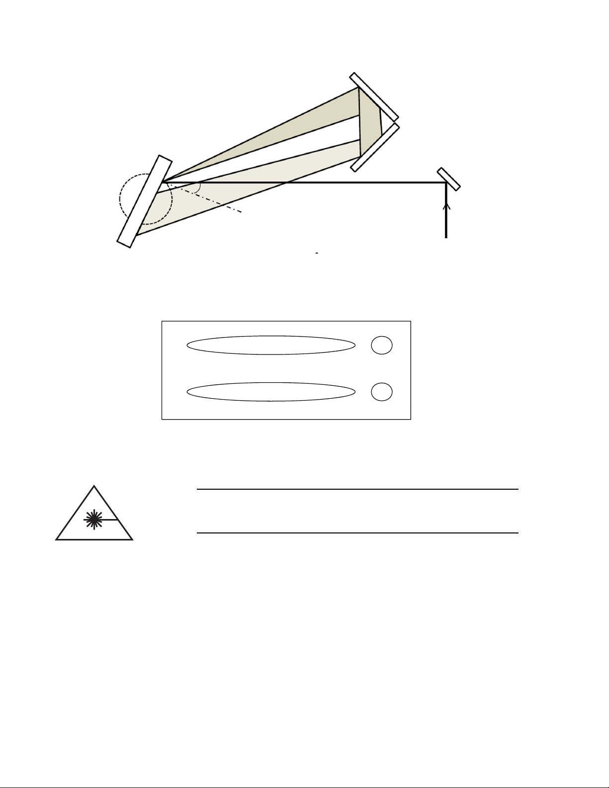
Libra Operator’s Manual
132
CM2
CG
CM3
26.5°
Normal
Figure 7-22. Femto Compressor Beam Path through the Horizontal Retroreflector
CM1
4
Figure 7-23. Correct Beam Pattern and Order of Incidence on the Compressor Grating
Verify that no laser light is present before lowering your head to
read the grating rotation stage angle.
2. Record the CG rotation angle.
3. Install alignment targets at A5 and A4.
4. Enable the Pockels cells, and adjust Delay 2 to optimize the
unseeded power output.
5. Using RM9 and CM1, align the beam to A5 and A4, respectively.
6. Rotate CG to obtain the beam pattern shown in Figure 7-23.
The nominal CG rotation angle is given below:
• 52
o
counterclockwise from normal for USP systems
7 - 34
Page 89

Optical Alignment
Compressor Grating Yaw Angle Adjustment
• 26.5
7. Check for clipping on all compressor optics, including the
final output beam.
8. If clipping exists, or if the beam pattern does not match
Figure 7-23 on page 7-34, recheck the alignment to A4 and
A5. Proceed through the following sections if necessary.
Refer to “Compressor Grating Yaw Angle Adjustment” on
page 7-11. The yaw angle may also be checked with the unseeded
RGA output beam as described below:
Do not allow a high-power beam to reflect from the compressor
grating back into the RGA. Permanent optical damage will
result.
1. Adjust Delay 2 earlier in time to reduce the unseeded power
output to 100 to 200 mW.
o
clockwise from normal for Femto systems
Horizontal Retroreflector Adjustment
2. Use RM9 and CM1 to recenter the beam on A5 and A4 if
necessary.
3. Perform the zero- and first-order alignment as described in
“Stretcher Grating Yaw Angle Adjustment” on page 7-9. Align
the reflections from CG to A5.
1. If not already done, adjust Delay 2 earlier in time to reduce the
unseeded power output to 100 to 200 mW.
2. Install a beam block in front of the CM4-5 assembly.
3. Observe the beam pattern on CG and compare it to Figure 7-23
on page 7-34. Only the top spot and stripe will be visible.
4. If the stripe is not in the correct location horizontally, rotate
and/or translate the CM2-3 assembly to obtain the correct
pattern on CG, and also avoid clipping on CG, CM2, and CM3.
• Do not adjust the CM2 or CM3 control knobs.
• Do not move the baseplate; but rather the upper part of
the mount, which holds the CM2 and CM3 optics themselves.
5. If the stripe is displaced vertically:
7 - 35
Page 90

Libra Operator’s Manual
a.) Rotate and translate the CM2-3 assembly so that the
reflection from CM2 propagates directly back to CG.
Firmly secure the assembly back down after moving it.
b.) Adjust the CM2 vertical control knob to set the stripe to
the same height as the spot.
c.) Rotate and translate the CM2-3 assembly to obtain the
CG beam pattern shown in Figure 7-23. Firmly secure
the assembly back down after moving it.
d.) If the stripe is still displaced vertically, adjust the CM3
vertical control knob to set the stripe to the same height
as the spot.
Vertical Retroreflector Adjustment
Compressor Spatial Chirp Removal
1. If not already done, adjust Delay 2 earlier in time to reduce the
unseeded power output to 100 to 200 mW.
2. Remove the beam block from in front of the CM4-5 assembly.
3. Observe the beam pattern on CG and compare it to Figure 7-23
on page 7-34.
4. If the bottom spot (#4 in Figure 7-23) is not directly below
spot #1, rotate the entire CM4-5 assembly to line them up.
Translate the assembly if necessary to avoid clipping the
compressor input and output beams.
5. If the bottom stripe (#3 in Figure 7-23) is displaced vertically
from spot #4, adjust the CM5 vertical control knob to set the
stripe to the same height as the spot.
6. If the beam is clipping vertically on CM4, translate CM4 and
CM5 (both mirrors slide together) up or down to avoid clipping. This also changes the output beam height.
Spatial chirp in the compressor can be monitored with a spectrometer and slit, as described in “Stretcher Spatial Chirp Removal” on
page 7-12.
A more precise method requires the output beam to be focused onto
a camera or M2 device with a long-focal-length lens
(+500 to +2000 cm). Spatial chirp introduced by the compressor
will cause an elliptical beam shape at the focus and a degraded M
value.
2
7 - 36
Page 91

Optical Alignment
Use wedged beam splitters and/or filters before focusing the
Libra output beam to avoid damage to the camera optics.
1. Focus the compressor output beam onto a camera or CCD.
Note the shape and location of the beam at the focal point.
2. Make a small discrete adjustment to the horizontal control
knob of CM3. This will move the beam on the screen.
3. Rotate the entire CM4-5 assembly to restore the original beam
location on the screen.
4. If the focused beam profile is more round, go back to step 2.
and adjust CM3 again in the same direction. If the profile is
more elliptical, adjust CM3 in the opposite direction.
5. Monitor the CG beam pattern, and check for clipping on all
compressor optics. If the adjustments in this procedure result
in clipping, iterate with compressor alignment procedures as
necessary.
Pulse Width Optimization
The primary adjustment for pulse optimization is the compressor
delay stage, which translates the CM2-3 assembly away from or
toward the compressor grating. The Libra includes a remote control
for fine compressor delay adjustments.
The stage has a locking lever which must be engaged for the remote
control to be functional. For large delay adjustments, unlock the
lever and use the large thumbscrew to move the CM2-3 assembly
along the stage rail. Refer to Figure 7-24.
To further optimize the pulse width or shape, make small changes to
the stretcher and compressor grating angles with the external grating
control knob(s). Each time either grating is moved, the delay stage
will need to be reoptimized. Systematically iterate grating and delay
stage adjustments to optimize the pulse.
Significant grating angle changes will alter the system alignment. It
may be necessary to iterate grating angle changes with the alignment
procedures described in this chapter. Monitor the compressor optics
and the output beam for clipping, and iterate with compressor alignment procedures if necessary.
7 - 37
Page 92
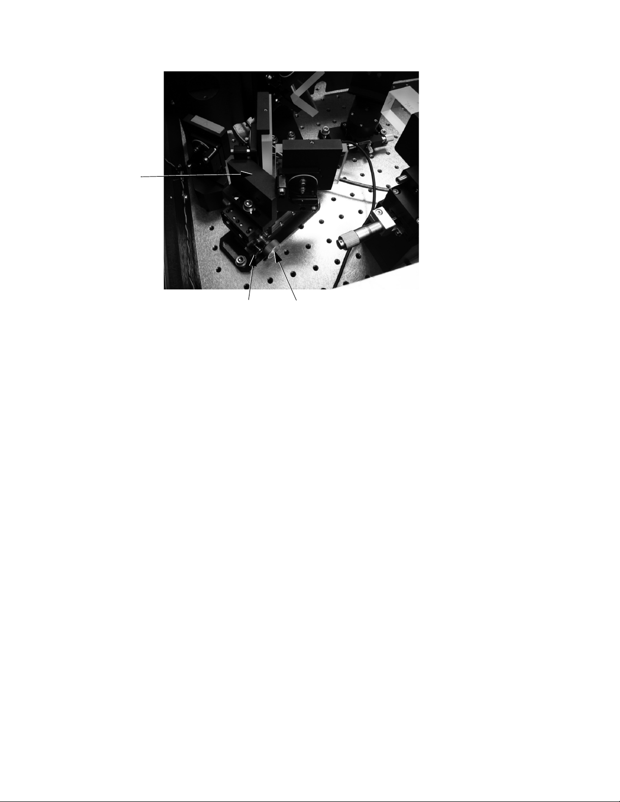
Libra Operator’s Manual
CM2-3 Mount
Locking lever Thumbscrew
Figure 7-24. Compressor Delay Stage Controls
7 - 38
Page 93

Fundamental Theory
SECTION EIGHT: FUNDAMENTAL THEORY
Ti:Sapphire Laser Theory
Chirped Pulse Amplification
The titanium ion Ti3+ is responsible for the laser action of
Ti:Sapphire. Ti:Sapphire is a crystalline material produced by introducing Ti2O3 into a melt of Al2O3. A boule of material is grown from
the melt where Ti3+ ions are substituted for a small percentage of the
Al3+ ions. The electronic ground state of the Ti3+ ion is split into a
pair of vibrationally broadened levels. Absorptive transitions occur
over a broad range of wavelengths from 400 to 600 nm. Fluorescence occurs from the lower vibrational levels of the excited state to
the upper vibrational levels of the ground state.
Although the fluorescence band extends over wavelengths shorter
than 600 nm, the long-wavelength side of the absorption band overlaps the short-wavelength side of the fluorescence spectrum. Therefore, lasing is only possible at wavelengths longer than 660 nm. An
additional weak absorption band that overlaps the fluorescence
spectrum further reduces the tuning range. Practically speaking in a
laser, the tuning range is also largely affected by the optical coatings.
Solid-state amplifiers have high saturation fluences, making it
possible to extract relatively large energies from modest-scale laser
systems. Ti:Sapphire also has large gain-bandwidth, which is necessary to amplify sub-picosecond pulses. A limitation comes from the
tendency of bright beams to self-focus destructively (a result of
non-linearity in the index of refraction), which makes it necessary to
limit the intensity present in amplifiers of reasonable length to less
than 10 GW/cm
2
.
The technique of chirped pulse amplification (CPA) removes this
obstacle. Briefly, the idea is to initially generate a weak but
short-duration pulse. The next step is to stretch its pulse duration,
thus significantly reducing its brightness (or peak power). This
low-brightness optical pulse is then amplified, with the probability
of self-focusing induced damage significantly reduced. Following
amplification, the pulse is recompressed to near its original duration.
A device that delays certain wavelengths relative to others can
stretch a short pulse over a longer time or, alternatively, compress a
long pulse into a shorter one. A diffraction grating, which reflects
different wavelengths at different angles, can serve as a basis for
such a device.
8 - 1
Page 94
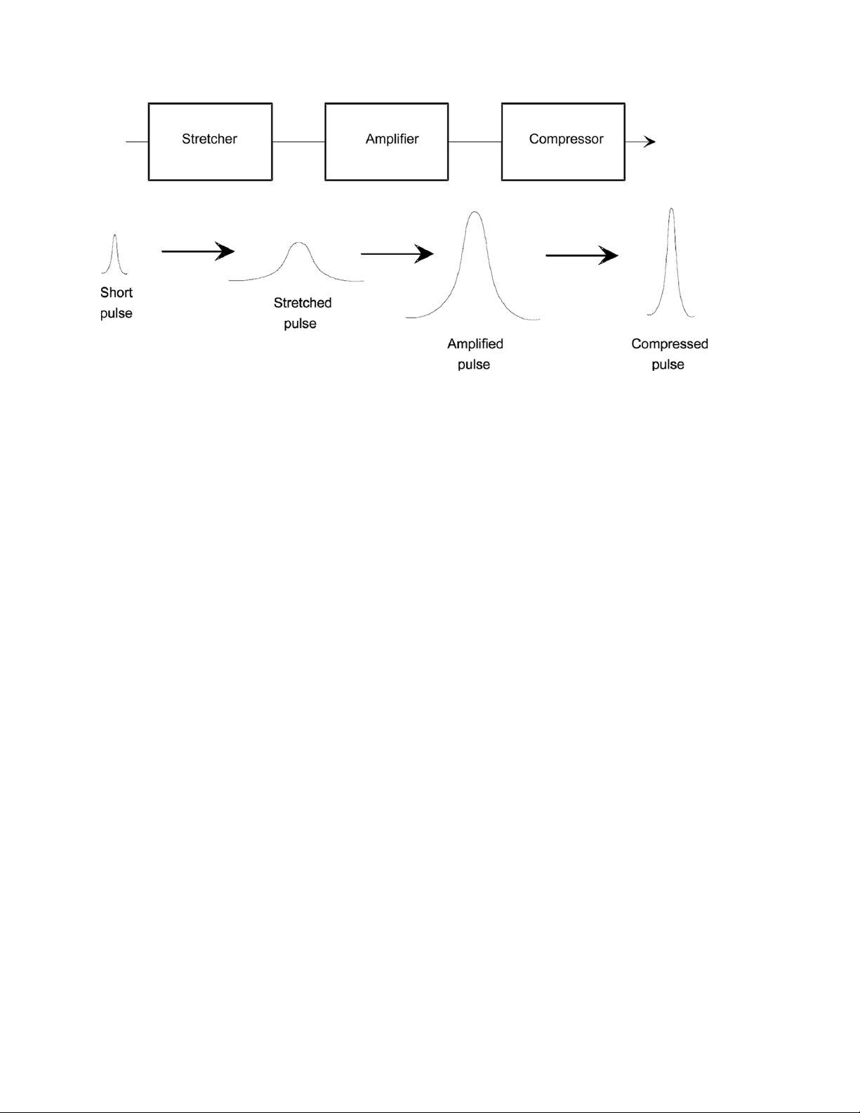
Libra Operator’s Manual
Figure 8-1. Chirped Pulse Amplification Principle
A grating can be arranged, with some other optical components, in
such a way to send the higher-frequency (bluer) light over a longer
path than the lower-frequency (redder) light, stretching out the
pulse. Such a pulse has a positive group velocity dispersion (GVD),
and can be described as being “positively chirped”. Conversely,
delaying the redder light more than the blue reverses the process,
thus compressing the pulse.
Pulse Stretching and Compression
The Libra employs the CPA technique. A low-energy, short-duration
pulse is initially stretched by as much as 10,000 times using a
single-grating pulse stretcher. A Ti:Sapphire regenerative amplifier
amplifies the pulse by a factor of ~106. A single grating compressor
then recompresses the pulse to near its original duration.
Pulse stretching and compression can be achieved with the use of
diffraction gratings. In a pulse stretcher, the input beam is incident
on a diffraction grating, which causes the different frequencies to
disperse. The grating can be configured in such a way so the bluer
frequency components must travel further through the stretcher than
the redder components. The result is that the redder frequency
components exit the stretcher first, and the pulse has been stretched.
Figure 8-2 shows a simplified pulse stretcher, which demonstrates
the concept but is not representative of the stretcher found in the
Libra.
8 - 2
Page 95
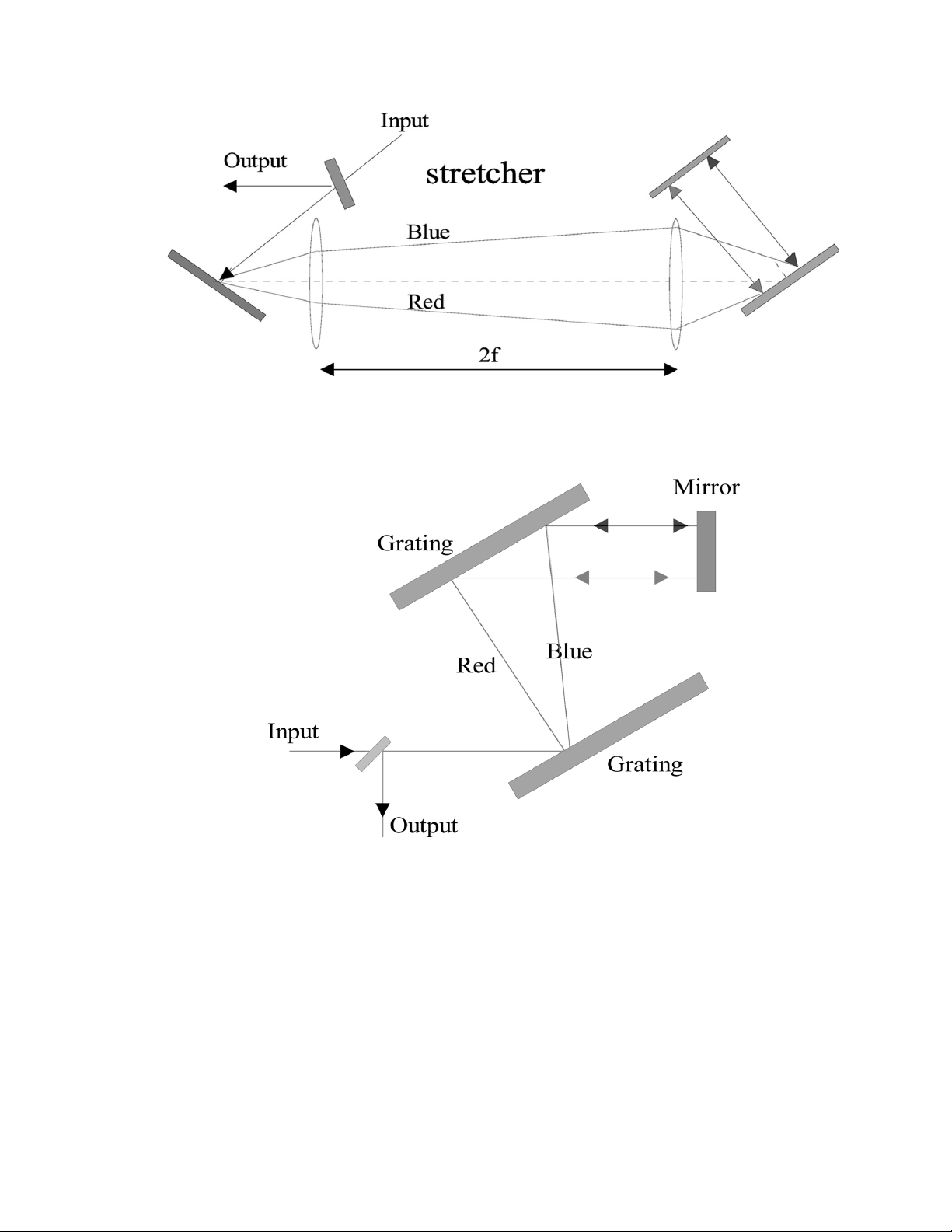
Figure 8-2. Pulse Stretcher Principle
Fundamental Theory
Regenerative Amplification
Figure 8-3. Pulse Compressor Principle
Pulse compression is essentially the reverse of pulse stretching. In
this case, however, the gratings are arranged so that the bluer
frequencies travel the shortest path, and therefore “catch up” with
the redder frequencies, thus compressing the pulse.
Regenerative amplifiers, seeded by low-energy laser pulses, are an
efficient means of obtaining high-energy, high-peak power pulses.
The principle of regenerative amplification is to confine, by polar-
8 - 3
Page 96

Libra Operator’s Manual
ization, a single pulse (selected from a modelocked train), amplify it
to an appropriate energy level, and then cavity dump the output. See
also “Seeded Operation” on page 7-26.
Typically, an input pulse of only a few nanojoules of energy can be
amplified to over 1 mJ in a single Ti:Sapphire laser rod. This represents an overall amplification of greater than 106. The amplification
takes place as the optical pulse passes through the laser rod, which
has been optically excited by a pulse from an Nd:YLF laser. The
amplification of the laser rod in a single pass is typically small −
only about 3 to 4. However, the regenerative amplification technique allows the pulse to multipass the rod resulting in a much
higher overall gain.
8 - 4
Page 97

Warranty
WARRANTY
Coherent, Inc. warrants to the original purchaser (the Buyer) only,
that the laser system, that is the subject of this sale, (a) conforms to
Coherent's published specifications and (b) is free from defects in
materials and workmanship.
Laser systems are warranted to conform to Coherent's published
specifications and to be free from defects in materials and workmanship for a period of twelve (12) months. This warranty covers travel
expenses for the first ninety (90) days. For systems that include
installation in the purchase price, this warranty begins at installation
or thirty (30) days from shipment, whichever occurs first. For
systems which do not include installation, this warranty begins at
date of shipment.
Optical Products
Conditions of Warranty
Coherent optical products are unconditionally warranted to be free
of defects in materials and workmanship. Discrepancies must be
reported to Coherent within thirty (30) days of receipt, and returned
to Coherent within ninety (90) days. Adjustment is limited to
replacement, refund or repair at Coherent's option.
On-site warranty services are provided only at the installation point.
If products eligible for on-site warranty and installation services are
moved from the original installation point, the warranty will remain
in effect only if the Buyer purchases additional inspection or installation services at the new site.
For warranty service requiring the return of any product to Coherent,
the product must be returned to a service facility designated by
Coherent. The Buyer is responsible for all shipping charges, taxes
and duties covered under warranty service.
Parts replaced under warranty shall become the property of Coherent
and must be returned to Coherent, Inc., Santa Clara, or to a facility
designated by Coherent. The Buyer will be obligated to issue a
purchase order for the value of the replaced parts and Coherent will
issue credit when the parts are received.
9 - 1
Page 98

Libra Operator’s Manual
Other Products
Responsibilities of the Buyer
Other products not specifically listed above are warranted to, (a)
conform to Coherent's published specifications and (b) be free from
defects in materials and workmanship. This warranty covers parts
and labor and is for a period of twelve (12) months from the date of
shipment.
The Buyer must provide the appropriate utilities and operating environment outlined in the product literature and/or the Pre-installation
Manual. Damage to the laser system caused by failure of Buyer’s
utilities or the Buyer's failure to maintain an appropriate operating
environment, is solely the responsibility of the Buyer and is specifically excluded from any warranty, warranty extension, or service
agreement.
The Buyer is responsible for prompt notification to Coherent of any
claims made under warranty. In no event will Coherent be responsible for warranty claims later than seven (7) days after the expiration of the warranty.
Limitations of Warranty
The foregoing warranty shall not apply to defects resulting from:
1. Components or accessories with separate warranties manufactured by companies other than Coherent.
2. Improper or inadequate maintenance by Buyer.
3. Buyer-supplied interfacing.
4. Operation outside the environmental specifications of the
product.
5. Improper site preparation and maintenance.
6. Unauthorized modification or misuse.
Coherent assumes no responsibility for customer-supplied material.
The obligations of Coherent are limited to repairing or replacing,
without charge, equipment which proves to be defective during the
warranty period. Repaired or replaced parts are warranted for the
duration of the original warranty period only. This warranty does not
cover damage due to misuse, negligence or accidents, or damage due
to installations, repairs or adjustments not specifically authorized by
Coherent.
9 - 2
Page 99

Warranty
This warranty applies only to the original Buyer at the initial installation point in the country of purchase, unless otherwise specified in
the sales contract. Warranty is transferable to another location or to
another Buyer only by special agreement which will include additional inspection or installation at the new site.
THE WARRANTY SET FORTH ABOVE IS EXCLUSIVE IN
LIEU OF ALL OTHER WARRANTY, WHETHER WRITTEN,
ORAL OR IMPLIED, AND DOES NOT COVER INCIDENTAL
OR CONSEQUENTIAL LOSS. COHERENT SPECIFICALLY
DISCLAIMS THE IMPLIED WARRANTIES OF MERCHANTABILITY AND FITNESS FOR A PARTICULAR PURPOSE.
9 - 3
Page 100

Libra Operator’s Manual
9 - 4
 Loading...