

Page 1

User Manual
LaserCam-HR
Beam Diagnostics Digital CMOS Camera
USB 2.0
™
Page 2

Page 3

User Manual
LaserCam-HR
Beam Diagnostics Digital
CMOS Camera
USB 2.0
7470 SW Bridgeport Rd.
Portland, OR 97224
Page 4

LaserCam-HR User Manual
This document is copyrighted with all rights reserved. Under
the copyright laws, this document may not be copied in whole
or in part or reproduced in any other media without the
express written permission of Coherent, Inc. Permitted copies
must carry the same proprietary and copyright notices as were
affixed to the original. This exception does not allow copies to
be made for others, whether or not sold, but all the material
purchased may be sold, given or loaned to another person.
Under the law, copying includes translation into another
language.
Coherent and the Coherent Logo are registered trademarks of
Coherent, Inc. LaserCam-HR, BeamView Analyzer, and
BeamView-USB are trademarks of Coherent, Inc.
Every effort has been made to ensure that the data given in
this document is accurate. The information, figures, tables,
specifications and schematics contained herein are subject to
change without notice. Coherent makes no warranty or
representation, either expressed or implied with respect to this
document. In no event will Coherent be liable for any direct,
indirect, special, incidental or consequential damages
resulting from any defects in its documentation.
Technical Support
In the U.S.:
Should you experience difficulties with your product, or need
technical information, please visit our website:
www.Coherent.com
either telephoning our Technical Support Hotline at
1.800.343.4912, or e-mailing our Support Team at
[email protected]. Telephone coverage is
available Monday through Friday (except U.S. holidays).
If you call outside our office hours, your call will be taken by
our answering system and will be returned when the office
reopens.
If there are technical difficulties with your product that cannot
be resolved by support mechanisms outlined above, please
. You can obtain additional support by
ii
Page 5

e-mail or telephone Coherent Technical Support with a
description of the problem and the corrective steps attempted.
When communicating with our Technical Support
Department, via the web or telephone, the model and serial
number of the product will be required by the Support
Engineer responding to your request.
Outside the U.S.:
If you are located outside the U.S., visit our website for
technical assistance, or telephone our local Service
Representative. Representative phone numbers and
addresses can be found on the Coherent website:
www.Coherent.com
Coherent provides web and telephone technical assistance as
a service to its customers and assumes no liability thereby for
any injury or damage that may occur contemporaneous with
such services. These support services do not, under any
circumstances, affect the terms of any warranty agreement
between Coherent and the buyer. Operating a Coherent
product with any of its interlocks defeated is always at the
operator's risk.
.
iii
Page 6

LaserCam-HR User Manual
iv
Page 7

Table of Contents
TABLE OF CONTENTS
Preface ......................................................................................................... vii
U.S. Export Control Laws Compliance ....................................................... vii
Publication Updates ..................................................................................... vii
Symbols Used in This Document ............................................................... viii
Safety ...................................................................................................................1
Declaration of Conformity..............................................................................3
Description .......................................................................................................5
Setup ....................................................................................................................7
Software Installation .......................................................................................7
Cabling............................................................................................................8
USB Cable .............................................................................................8
Trigger Cable .........................................................................................9
Mounting the Camera .....................................................................................9
Operation ........................................................................................................11
Pixel Spacing ................................................................................................12
Power On ......................................................................................................12
Warm-Up Time .............................................................................................12
Maximum Power Levels...............................................................................13
Saturation ......................................................................................................13
Trigger...........................................................................................................13
Trigger In .............................................................................................13
Trigger Out...........................................................................................14
Low Distortion Faceplate (LDFP) ................................................................14
Dust/Dirt .......................................................................................................15
Cleaning the Sensor ......................................................................................15
Fringes ..........................................................................................................16
v
Page 8

LaserCam-HR User Manual
How to Get the Most From Your LaserCam-HR System .............................17
Warranty .........................................................................................................21
Limited Warranty ..........................................................................................21
Warranty Limitations ....................................................................................22
Obtaining Service .........................................................................................22
Product Shipping Instructions.......................................................................24
Appendix A: Specifications ................................................................25
LIST OF TABLES
1. Pixel Spacing for LaserCam-HR ...............................................................12
2. Saturation ...................................................................................................13
3. Coherent Service Centers...........................................................................23
4. Specifications.............................................................................................25
LIST OF FIGURES
1. USB Cable ...................................................................................................8
2. Trigger Cable ...............................................................................................9
3. Mounting Configurations...........................................................................10
4. Dust on Filter Glass ...................................................................................15
5. Fringes .......................................................................................................17
vi
Page 9

Preface
Preface
U.S. Export
Control Laws
Compliance
This manual contains user information for the
LaserCam-HR™ Beam Diagnostics Digital CMOS
Camera.
It is the policy of Coherent to comply strictly with U.S.
export control laws.
Export and re-export of lasers manufactured by Coherent
are subject to U.S. Export Administration Regulations,
which are administered by the Commerce Department.
In addition, shipments of certain components are regulated by the State Department under the International
Traffic in Arms Regulations.
The applicable restrictions vary depending on the
specific product involved and its destination. In some
cases, U.S. law requires that U.S. Government approval
be obtained prior to resale, export or re-export of certain
articles. When there is uncertainty about the obligations
imposed by U.S. law, clarification should be obtained
from Coherent or an appropriate U.S. Government
agency.
Publication Updates
To view information that may have been added or
changed since this publication went to print:
1. Connect to www.Coherent.com
2. Type LaserCam-HR in the Site Search box (top
left of the screen) and then click the “>>” button.
vii
.
Page 10

LaserCam-HR User Manual
Symbols Used in This Document
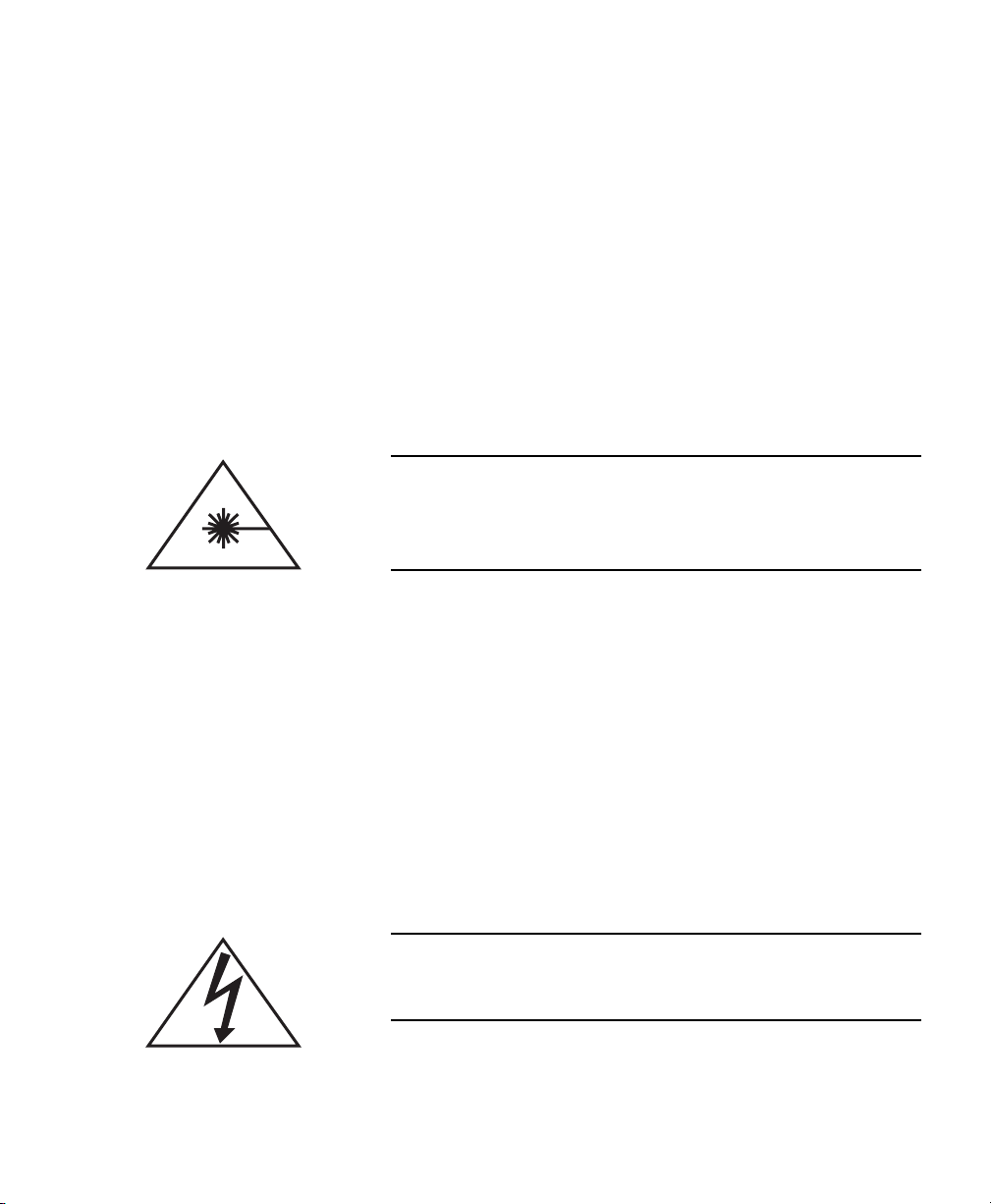
This symbol is intended to alert the operator to the
presence of exposure to hazardous visible and invisible laser radiation.
This symbol is intended to alert the operator to the
presence of dangerous voltages associated with the
product that may be of sufficient magnitude to constitute a risk of electrical shock.
This symbol is intended to alert the operator to the
presence of important operating and maintenance
instructions.
viii
Page 11
Safety
SAFETY
Carefully review the following safety information to
avoid personal injury and to prevent damage to this
instrument or any sensor connected to it. This equipment
contains no user-serviceable parts. For service information, refer to “Obtaining Service” on page 22.
The use and measuring of lasers is potentially
dangerous. This instrument operates over wavelengths that include non-visible laser emissions.
Proper laser operating practice in accordance with manufacturer recommendations is vital.
Eyewear and other personal protective equipment must
be used in accordance with applicable laws and regulations.
If in doubt of correct operating procedures, consult the
laser manufacturer and your laser safety officer.
The equipment is not for use in critical medical environments.
Do not operate the camera if its panels are removed
or any of the interior circuitry is exposed.
1
Page 12
LaserCam-HR User Manual
Do not operate the camera in wet or damp conditions,
or in an explosive atmosphere.
Operate the camera only within the specified voltage
range.
Do not operate the camera if there are suspected failures. Refer damaged equipment to qualified
Coherent service personnel.
2
Page 13

Declaration of Conformity
Safety
3
Page 14

LaserCam-HR User Manual
4
Page 15

Description
DESCRIPTION
The LaserCam-HR™ Beam Diagnostics Digital CMOS
camera utilizes a laser grade
CMOS sensor for detection and analysis of laser beam
profiles from 270 µm to 5.5 mm in diameter with 6.7 µm
by 6.7 µm spatial resolution over the spectral range of
300 to 1100 nm. LaserCam-HR characteristics include
excellent signal-to-noise ratio and linear response for
accurate beam dimension and uniformity measurements,
and high overexposure protection for distortion-less
measurements of saturated beam profiles.Other features
include:
• USB 2.0 digital interface
2
/
-inch progressive scan
3
• Compact design minimizes space required in
optical train
• Mountable in any orientation for maximum flexi-
bility. Camera markings provide for X, Y, and
38.6° alignments.
• Uses a single interface cable for data and power
• A Low Distortion Faceplate (LDFP) that mini-
mizes room light, protects the CMOS array, and
provides laser grade quality attenuation of 2500:1
• High sensitivity and dynamic range
• No lag, geometric distortion, or image burn-in
5
Page 16

LaserCam-HR User Manual
• Accepts C-mount optics, including all Coherent
• High resolution: 1280 x 1024 active picture
• Requires only USB 2.0 connections
• CE compliant when used with a CE-compliant
optical sampling, attenuation, and UV conversion
accessories.
elements (pixels)
computer and cables
6
Page 17

SETUP
This section discusses the following topics:
• Software installation (this page)
• Cabling (page 8)
• Mounting the camera (page 9)
Setup
Software Installation
For complete software installation instructions, refer to
the BeamView-USB With LaserCam-HR Quick Start
Guide (1086147) that shipped with your product. To
view that document online:
1. Connect to out website: www.Coherent.com.
2. Type LaserCam-HR in the Site Search box (top
left of the screen) and then click the “>>” button.
3. Click the “LaserCam-HR” link in the list of search
results.
4. Click the “BeamView-USB With LaserCam-HR
Quick Start Guide” link (right side of the page,
under the Literature & Documentation” heading).
5. If the Download Request form appears (which only
happens the first time you visit our website and
request literature), fill in the information and then
click the “Submit” button at the bottom of the form.
7
Page 18

LaserCam-HR User Manual
Cabling
USB Cable
Place the LaserCam-HR at the location where the beam
will be measured. To protect the faceplate from dust,
leave the dust cap installed until ready to make measurements.
Connect the USB 2.0 cable to the USB 2.0 connector on
the LaserCam-HR camera (see Figure 1). Do not
connect the cable to the computer until instructed to do
so.
Figure 1. USB Cable
LaserCam-HR produces a standard UB 2.0 digital signal.
It will interface through the USB 2.0 connector of any
compatible PC using Coherent BeamView Version 4.3
software.
Connecting the optional trigger cable is discussed next.
8
Page 19

Setup
Trigger Cable
Mounting the Camera
For information about the LaserCam-HR trigger, refer to
“Trigger” on page 13.
Figure 2. Trigger Cable
LaserCam-HR is designed to be mounted in any rotational position (in Figure 3, θ = 0 to 360°) with a
1
/
-20
4
threaded mounting post (for mounting post location, see
“Physical Dimensions” on page 25). Alignment marks
permit the camera to be rotated and aligned with the
vertical, horizontal, and diagonal orientation of the
sensor. The diagonal alignment mark helps identify the
maximum diagonal position of the sensor array.
Depending on the mounting orientation of the camera,
the diagonal alignment mark will be either 38° or 52°
off-axis to account for the rectangular shape of the
9
Page 20

LaserCam-HR User Manual
sensor. Note that the beam movement on the camera will
not match the beam movement on the monitor for all
positions.
θ
Diagonal Alignment Mark
Figure 3. Mounting Configurations
10
Page 21

Operation
OPERATION
This section discusses the following topics:
• Pixel spacing (page 12)
• Power on (page 12)
• Warm-up time (page 12)
• Maximum power levels (page 13)
• Saturation (page 13)
• Trigger (page 13)
• Low Distortion Face Plate (LDFP) (page 14)
• Dust/dirt (page 15)
• Cleaning the sensor (page 15)
• Fringes (page 16)
• How to get the most from your LaserCam-HR
system (page 17)
11
Page 22

LaserCam-HR User Manual
Pixel Spacing
The LaserCam-HR pixel spacing values are shown in
Table 1
Table 1. Pixel Spacing for LaserCam-HR
2
/
-INCH FORMAT
3
Horizontal Spacing Vertical Spacing
LaserCam-HR 6.70 µm 6.70 µm
Power On
LaserCam-HR has no ON/OFF switch. As soon as power
is applied to the camera via the USB 2.0 connection, it
begins operating.
Warm-Up Time
The LaserCam-HR does not require warm-up. However,
if it is used to make high-accuracy measurements, it
should be allowed to warm-up at least 15 minutes to
insure best baseline (background) stability.
For best results, the background map should be taken
after the camera warm-up period.
12
Page 23

Operation
Maximum Power Levels
The camera will saturate at approximately 16.0 µW/cm
at 633 nm wavelength, 320.0 µW/cm2 at 1.06 µm wavelength, or 3.2 µJ/cm2 pulsed 1.06 µm wavelength.
Damage may occur at power levels that exceed 10,000
times saturation power density.
Saturation
Table 2. Saturation
WAVELENGTH ON ARRAY ON LDFP
633 nm (CW) 16.0 µW/cm
1064 nm (CW) 320.0 µW/cm
2
2
40.0 mW/cm
800.0 mW/cm
2
2
2
1064 nm (Pulse) 3.2 µJ/cm
Trigger
Trigger In
2
8.0 mJ/cm
2
The LaserCam-HR trigger permits the beam diagnostic
system to interface to pulsed lasers and transient optical
events including single shot lasers.
Trigger In uses the BNC connector labeled “IN” on the
LaserCam-HR trigger cable. This 5 VDC, TTL
input—available on the rising or falling edge—causes
the camera to immediately reset and begin integrating
13
Page 24

LaserCam-HR User Manual
light. The Trigger In delay is 150 µS. This is the time it
takes for the camera to begin integrating light once the
trigger signal occurs. The LaserCam-HR is capable of
sampling laser pulse repetition rates of up to 100 Hz
without averaging adjacent pulses.
Trigger Out
Low Distortion Faceplate (LDFP)
Trigger Out has been eliminated on this version of
LaserCam. Coherent suggests that an external pulse
generator be used if the laser under test does not supply
a “sync-out” signal. Connect the pulse generator to the
Trigger In connector. A delayed trigger should be
applied to the Enable or Trigger input connector of the
laser. Keep in mind that integration begins 150 µS after
the rising edge of the camera trigger (Trigger In), so you
must delay the laser enable pulse by 150 µS, minus any
delay in the laser firing circuit.
The Low Distortion Faceplate provides a protective
window for the camera array that also acts as a background attenuator with 0.04% to 0.05% typical. The
LDFP is made of laser grade filter glass that minimizes
interference fringes (refer to “Fringes” on page 16) and
does not distort the beam image. The LDFP limits room
light, instrumentation lights, and flash lamp light from
reaching the camera sensor. These lights cause a background level that may not be effectively subtracted by
the Background Subtraction Wizard.
14
Page 25

Operation
Dust/Dirt
If low intensity spots or small circles are noticed in the
camera video then dust may be present on the CMOS
sensor or on the Low Distortion Faceplate (see
Figure 4 on page 15). Dust on the LDFP filter glass can
cause distortion in the form of small circular diffraction
rings, or can cause low-intensity spots if present on the
sensor array. Observe the defects with a flashlight or a
small light illuminating the camera. If the defect moves
when the illumination angle is changed, then the dust is
on the LDFP. Otherwise it is dust on the sensor array.
Use clean air at low pressure, or methanol and lens tissue
to clean the LDFP filter glass. Take all necessary precautions to insure that nothing comes in contact with the
sensor surface.
Cleaning the Sensor
Figure 4. Dust on Filter Glass
Avoid unnecessary exposure of the sensor to dust and
dirt. If the surface of the sensor has to be cleaned, never
use any kind of cloth, tissue, or brush, and strictly avoid
the use of any kind of cleaning fluid. Only use clean, dry,
micro-filtered low-pressure air to gently blow away
particles from the surface of the sensor. Contact
15
Page 26

LaserCam-HR User Manual
Coherent Customer Service if the sensor requires additional cleaning (refer to “Coherent Service Centers” on
page 23 for contact information).
Touching the sensor will cause irreversible damage.
Always cover the sensor with a dust cap when not in
use.
Fringes
If the LDFP filter glass is installed in the camera, fringes
may appear in the video (see Figure 5). The fringe
pattern is due to a second reflection off the sensor and
LDFP superimposing back onto the original beam image.
This situation can be corrected by loosening the C-mount
16
Page 27

Operation
setscrew and rotating the LDFP housing until the fringes
are no longer present. Slightly turning the camera with
respect to the laser beam may also reduce this effect.
Figure 5. Fringes
How to Get the Most From Your LaserCam-HR System
The LaserCam-HR has been carefully designed to
provide accurate measurements of the spatial and intensity characteristics of laser beams. Significant attention
has been paid to every aspect of the instrument that
impacts data accuracy. The following items will help you
obtain the best performance from your LaserCam-HR:
• System tray—Turn off everything that is
non-essential to the running of the computer. This
action will help assure the fastest frame update rate
possible.
• Resolution—Select 640 x 512 x 8 resolution to
obtain the highest update rates.
• RAM—A minimum of 512 MB is required. 1 GB
is recommended. More is typically better.
• Select RAM for the buffer to obtain the highest
update rates.
17
Page 28
LaserCam-HR User Manual
• Processor speed—A minimum of 3.3 GHz is
• Keep all optics clean—Dirty LDFP, beam
• The Inclusion command provides control of the
recommended. Faster clock speeds provide higher
frame update rates. Again, “the faster the better.”
sampling, and attenuation optics will distort the
beam under test. It is important that you regularly
check these optical surfaces for dust, fingerprints,
and other contamination. Follow standard coated
optical surfaces cleaning techniques. Use the Inclusion command to reduce the size and amount of
data that is processed.
sensor area where calculations are performed.
Reducing this area can significantly increase frame
update rates and is especially effective with small
spot sizes.
Cleaning the sensor surface will void the warranty
and most likely will damage the camera.
It is strongly recommended that the LDFP always
be left in place and that the dust cap be used to
protect the LDFP when the instrument is not in use.
• Read the user documentation—The LaserCam-HR
is a complex piece of optical test equipment. Many
functions are included in the system that may not
be obvious to a casual or first-time user. Review
the LaserCam-HR User Manual (this manual) and
the BeamView-USB Help (accessed by clicking
the Help button in the BeamView software) to
learn about these useful functions. Many calcula-
18
Page 29
Operation
tions and functions that may at first appear to
require post-processing or exporting of the data to
another application are included in the instrument.
The user documentation is designed to explain all
of the functions in an easy-to-use format.
Observe standard Laser Safety procedures—The
eyes you save may be your own.
19
Page 30

LaserCam-HR User Manual
20
Page 31

Warranty
WARRANTY
This section includes information on the following
topics:
• Limited warranty (this page)
• Warranty limitations (page 22)
• Obtaining service (page 22)
• Product shipping instructions (page 24)
Limited Warranty
Coherent, Inc. (the “Company”) warrants its laser beam
diagnostic products (“Products”) to the original
purchaser (the “Customer”) that the product is free from
defects in materials and workmanship and complies with
all specifications, active at the time of purchase, for a
period of twelve (12) months.
If the Product fails and is returned to the Company within
one year following the date of purchase, the Company
will, at its option, repair or replace the Product or any
component found to be defective. This warranty applies
only to the original purchaser and is not transferable.
Coherent, Inc. will, at its option, repair or replace any
product or component found to be defective during the
warranty period. This warranty applies only to the original purchaser and is not transferable.
21
Page 32

LaserCam-HR User Manual
Warranty Limitations
The foregoing warranties shall not apply, and Coherent
reserves the right to refuse warranty service, should
malfunction or failure result from:
• Damage caused by improper installation, handling,
or use.
• Laser damage (including sensor elements damaged
beyond repair).
• Failure to follow recommended maintenance
procedures.
• Unauthorized product modification or repair.
• Operation outside the environmental specifications
of the product.
Coherent assumes no liability for Customer-supplied
material returned with Products for warranty service or
recalibration.
THIS WARRANTY IS EXCLUSIVE IN LIEU OF ALL
OTHER WARRANTIES WHETHER WRITTEN,
ORAL, OR IMPLIED. COHERENT SPECIFICALLY
DISCLAIMS THE IMPLIED WARRANTIES OF
MERCHANTABILITY AND FITNESS FOR A
PARTICULAR PURPOSE. IN NO EVENT SHALL
THE COMPANY BE LIABLE FOR ANY INDIRECT,
INCIDENTAL, OR CONSEQUENTIAL DAMAGES
IN CONNECTION WITH ITS PRODUCTS.
Obtaining Service
In order to obtain service under this warranty, Customer
must notify the Company of the defect before the expiration of the warranty period and make suitable arrangements for the performance of service. The Company
22
Page 33

Warranty
shall, in its sole discretion, determine whether to perform
warranty service at the Customer's facility, at the
Company's facility or at an authorized repair station.
If Customer is directed by the Company to ship the
product to the Company or a repair station, Customer
shall package the product (to protect from damage during
shipping) and ship it to the address specified by the
Company, shipping prepaid. The Company shall pay the
cost of shipping the Product back to the Customer in
conjunction with product failures within the first twelve
months of time of sale.
A Returned Material Authorization number (RMA)
assigned by the Company must be included on the
outside of all shipping packages and containers. Items
returned without an RMA number are subject to return to
the sender.
For the latest Customer Service information, refer to our
website: www.Coherent.com.
Detailed instructions on how to prepare a product for
shipping are shown under “Product Shipping Instructions” on page 24.
Table 3. Coherent Service Centers
LOCATION PHONE FAX E-MAIL
23
Page 34

LaserCam-HR User Manual
Product Shipping Instructions
To prepare the product for shipping to Coherent:
1. Contact Coherent Customer Service (refer to
Table 3 on page 23) for a Return Material Authorization number.
2. Attach a tag to the product that includes the name
and address of the owner, the person to contact, the
serial number, and the RMA number you received
from Coherent Customer Service.
3. Wrap the product with polyethylene sheeting or
equivalent material.
4. If the original packing material and carton are not
available, obtain a corrugated cardboard shipping
carton with inside dimensions that are at least 6 in
(15 cm) taller, wider, and deeper than the product.
The shipping carton must be constructed of cardboard with a minimum of 375 lb (170 kg) test
strength. Cushion the instrument in the shipping
carton with packing material or urethane foam on
all sides between the carton and the product. Allow
3 in (7.5 cm) on all sides, top, and bottom.
5. Seat the shipping carton with shipping tape or an
industrial stapler.
6. Ship the product to:
Coherent, Inc.
7470 SW Bridgeport Rd.
Portland, OR 97224
Attn: RMA # (add the RMA number you received
from Coherent Customer Service)
24
Page 35

APPENDIX A: SPECIFICATIONS
Table 4 lists specifications for the LaserCam-HR.
Table 4. Specifications
PARAMETER DESCRIPTION
GENERAL
Physical Dimensions
Appendix A: Specifications
68.1 mm
34.0 mm
34.0 mm
68.1 mm
45.3 mm
36.6 mm
1
-20 TPI
/
4
(optional M6 rotational mount available - part #1086781)
14.0 mm
23.0 mm
79.3 mm
8-32 16.9 mm
40.9 mm
26.9 mm
4.1 mm from housing
face to element face
locating surface
17.8 mm from LDFP to
element face locating
surface
25
Page 36

LaserCam-HR User Manual
Table 4. Specifications (Continued)
PARAMETER DESCRIPTION
2
/
Spectral Range
Camera Type Progressive scanning CMOS
Video Format 10-bit digital USB 2.0 hi-speed
-inch: Silicon, 300 to 1100 nm (400 to 1100 nm with LDFP)
3
Sensor Active Area 8.5 mm (H) x 6.8 mm (V) (
2
/
-inch format)
3
Sensor Elements 1280 (H) x 1024 (V)
Sensor Element Spacing 6.70 µm (H) x 6.70 µm (V)
Recommended Beam Diam. 0.20 mm min., 6.0 mm max. (1/e2)
Optical Dynamic Range > 1000 to 1
Dimensional Accuracy ± 1% (typical), ± 5% (over entire spectral and dimensional
range)
Pulse Trigger In TTL, rising or falling edge
Pulse Integration Timing Integration begins 150 µS after rising edge of Trigger In
Automatic Pulse Trigger 0 to 100% of camera peak response (user adjustable)
Max. Sample Rate 15 Hz (Live mode), 10 Hz (Run mode)
Noise, Peak 24 nW/cm2 (at 632.8 nm)
CW Saturation 40 mW/cm2 (at 632.8 nm) (with LDFP)
Pulsed Saturation 8 mJ/cm2 (at 1.06 µm) (with LDFP)
Damage Threshold 32 mJ/cm2 (at 1.06 µm) (without LDFP)
Distance to Image Plane 17.8 ± 0.5 mm (from front of LDFP)
Electronic Shutter 10 ms
26
Page 37

Table 4. Specifications (Continued)
PARAMETER DESCRIPTION
Weigh t 208 g, 235 g with cable
Lens Mount C-mount
Appendix A: Specifications
Threaded Mounting Post
I/O Connector USB 2.0 Type B
ELECTRICAL
Signal-to-Noise Ratio > 60dB (gain 0 dB, gamma 1.0)
Power Powered through USB 2.0 interface
Video Output Digital: USB 2.0
Black Level Self-adjusting
Exposure Time Set to 10 ms, no user adjustment
Synchronization Internal free-running (crystal)
Gamma 1.0
Gain No automatic gain control. Gain is factory set for optimum linear
ENVIRONMENTAL
1
/4-20
Optional M6 post available (part #1086781)
dynamic range.
Operating Temperature -20 to 60°C
Relative Humidity To 95% non-condensing
27
Page 38

LaserCam-HR User Manual
28
Page 39

Page 40

LaserCam-HR™ User Manual
© Coherent, Inc. 10/2005, Printed in the U.S.A.
Part No. 1082657, Rev. AB
 Loading...