

Page 1

User Manual
LabMax™-TOP
Laser Power/Energy Meter
Page 2

Page 3

User Manual
LabMax-TOP
Laser Power/Energy Meter
27650 SW 95th Ave.
Wilsonville, OR 97070
Page 4

LabMax-TOP User Manual
This document is copyrighted with all rights reserved. Under the copyright
laws, this document may not be copied in whole or in part or r eproduced in
any other media without the exp ress written perm ission of Coher ent, Inc.
Permitted copies must carry the same proprietary and copyright notices as
were affixed to the original. This exception does not allow copies to be
made for others, whether or not sold, but all the material purchased may
be sold, given, or loaned to another person. Under the law, copying
includes translation into another language.
Coherent, the Coherent Logo, and LabMax are trademarks or registered
trademarks of Coherent, Inc. All other trademarks or registered
trademarks are the property of their respective owners.
Patents referenced in this document were active as of the printing date of
the manual (see last page for date). The patents referenced herein may
have expired. Y ou are advised to check to see if the patents are still active:
http://portal.uspto.gov/external/portal/pair
Every effort has been made to ensure that the dat a given in this d ocument
is accurate. The information, figures, tables, specifications and schematics
contained herein are subject to change without notice. Coherent makes no
warranty or representation, either expressed or implied with respect to this
document. In no event will Coherent be liable for any direct, indirect,
special, incidental or consequential damages resulting from any defects in
its documentation.
.
Technical Support
In the US:
Should you experience any difficulties with your product or need any
technical information, please visit our website: www.Coherent.com
Additional support can be obtained by contacting our Technical Support
Hotline at 1.800.367.7890 (1.408.764.4557 outside the U.S.), or e-mail
the clock (except U.S. holidays and company shutdowns).
If you call outside our office hours, your call will be taken by our answering
system and will be returned when the office reopens.
If there are technical difficulties with your laser that cannot be resolved by
support mechanisms outlined above, e-mail, or telephone Coherent
Technical Support with a description of the problem and the corrective
steps attempted. When communicating with our Technical Support
Department via the web or telephone, the Support Enginee r responding to
your request will require the model and Laser Head serial number of your
laser system.
Outside the US:
If you are located outside the U.S., visit our website for technical
assistance or contact our local service representative. Representative
phone numbers and addresses can be found on the Coherent website:
www.Coherent.com
.
. T elephone cover age is available around
.
Coherent provides telephone and web technical assist ance as a service to
its customers and assumes no liability thereby for any injury or damage
that may occur contemporaneous with such services. These support
services do not affect, under any circumstan ces, the terms of any warranty
agreement between Coherent and the buyer. Operation of any Coherent
laser with any of its interlocks defeated is always at the operator's o wn risk
ii
Page 5

Table of Contents
TABLE OF CONTENTS
Preface .................................................................................................................................. xi
RoHS Compliance ................................................................................................................ xi
Export Control Laws Compliance ........................................................................................ xi
Signal Words and Symbols in this Manual........................................................................... xi
Signal Words............................................................................................................... xii
Symbols ..................................................................................................................... xiii
Battery Compliance ............................................................................................................ xiv
Publication Updates............................................................................................................ xiv
Firmware Updates............................................................................................................... xiv
Section One: Safety......................................................................................................... 1-1
Waste Electrical and Electronic Equipment (WEEE, 2002)............................................... 1-2
Declaration of Conformity.................................................................................................. 1-2
Section Two: Quick Start............................................................................................ 2-1
Measuring Power With a Thermopile or Optical Sensor.................................................... 2-2
Measuring Energy With a Pyroelectric Sensor................................................................... 2-3
Saving Data to a File on the Local Drive............................................................................ 2-4
Moving a File to the USB Flash Drive ............................................................................... 2-5
Section Three: Description ....................................................................................... 3-1
Product Overview ............................................................................................................... 3-1
Product Features ................................................................................................................. 3-2
Menu Layout....................................................................................................................... 3-3
Front Panel.......................................................................................................................... 3-4
Buttons....................................................................................................................... 3-4
Soft Keys.................................................................................................................... 3-5
Power On/Off Button................................................................................................. 3-5
Selection Knob........................................................................................................... 3-5
Side Panel ........................................................................................................................... 3-6
USB Flash Drive Connector ...................................................................................... 3-6
Mini-USB Connector................................................................................................. 3-6
RS-232 Connector...................................................................................................... 3-6
Sensor Connector....................................................................................................... 3-7
Power Jack Connector ............................................................................................... 3-7
Rear Panel........................................................................................................................... 3-7
Ext Trig Connector.....................................................................................................3-8
Analog Out Connector............................................................................................... 3-8
GPIB Connector......................................................................................................... 3-8
Battery Indicators................................................................................................................ 3-8
Battery Charging Procedure....................................................................................... 3-9
Dip Switch (OEM Mode) ................................................................................................. 3-10
Battery Pack Replacement................................................................................................ 3-11
iii
Page 6

LabMax-TOP User Manual
Battery Directive...................................................................................................... 3-11
AC Adapter....................................................................................................................... 3-12
Section Four: Operation.............................................................................................. 4-1
Units.................................................................................................................................... 4-1
MEASURE .........................................................................................................................4-1
Measurement Display and Range Selection .............................................................. 4-2
Measure Power .......................................................................................................... 4-2
Thermopile Sensors .......................................................................................... 4-2
Thermopile Quad Sensors................................................................................. 4-4
Optical Sensors ................................................................................................. 4-5
Measure Energy......................................................................................................... 4-6
Pulsed Thermopile Joules Mode....................................................................... 4-6
Collecting Pulsed Thermopile Joules Data Over a Host Port........................... 4-7
Thermopile Sensors, Long Pulse Joules........................................................... 4-7
Pyroelectric Sensors........................................................................................ 4-10
Triggering........................................................................................................4-12
Internal Triggering Mode................................................................................ 4-12
Trigger States and the Trigger Annunciator.................................................... 4-14
Pulse Sampling ............................................................................................... 4-14
Statistics................................................................................................................... 4-15
Statistics Calculations..................................................................................... 4-15
Detailed Procedures................................................................................................. 4-23
POSITION STABILITY................................................................................. 4-23
TUNE................................................................................................................................ 4-25
Strip Chart................................................................................................................ 4-25
Bar Chart.................................................................................................................. 4-26
TREND............................................................................................................................. 4-28
TREND Screen During Data Collection.................................................................. 4-30
TREND Screen After Data Collection..................................................................... 4-32
Detailed Procedures................................................................................................. 4-34
Name Log File ................................................................................................ 4-34
File Manager................................................................................................... 4-36
TREND Setup................................................................................................. 4-41
ZERO................................................................................................................................ 4-44
SETUP .............................................................................................................................. 4-45
Display Smoothing .................................................................................................. 4-46
Speedup.................................................................................................................... 4-48
Area Correction........................................................................................................ 4-49
Gain Compensation.................................................................................................. 4-51
Wavelength Correction ............................................................................................ 4-53
Wavelength Table Edit............................................................................................. 4-54
Adding a Wavelength...................................................................................... 4-55
Deleting a Wavelength.................................................................................... 4-56
Power Measure Units............................................................................................... 4-56
Resolution................................................................................................................ 4-57
Analog Output.......................................................................................................... 4-58
iv
Page 7

Table of Contents
Trigger...................................................................................................................... 4-58
Communications...................................................................................................... 4-61
Date/Time.................................................................................................................4-63
Energy Savings ........................................................................................................ 4-65
Screen Contrast........................................................................................................ 4-66
Serial Number.......................................................................................................... 4-68
Version ..................................................................................................................... 4-68
Soft Keys.................................................................................................................. 4-68
Detailed Procedures................................................................................................. 4-69
Save Current Config ....................................................................................... 4-69
Manage Configs.............................................................................................. 4-71
HELP ................................................................................................................................ 4-73
Context-Sensitive Help............................................................................................ 4-73
General Help............................................................................................................ 4-74
BACKLIGHT ................................................................................................................... 4-74
Section Five: Special Topics...................................................................................... 5-1
Analog Output..................................................................................................................... 5-1
Understanding the External Trigger Circuit........................................................................5-1
Section Six: Host Interface......................................................................................... 6-1
Special Considerations........................................................................................................ 6-1
Message Terminators ................................................................................................. 6-1
Messages Received by the Meter...................................................................... 6-1
Messages Sent by the Meter ............................................................................. 6-1
Using the RS-232 Interface........................................................................................ 6-2
Data Flow Control ............................................................................................ 6-2
Service Request................................................................................................. 6-2
Using the GPIB Interface........................................................................................... 6-2
IEEE-488.1 Interface Capabilities.................................................................... 6-2
Service Request................................................................................................. 6-3
Using the USB Interface............................................................................................ 6-3
Service Request................................................................................................. 6-3
Binary Streaming Data...................................................................................... 6-3
Notation Conventions ................................................................................................ 6-3
Syntax ........................................................................................................................ 6-4
Host Command Quick Reference ....................................................................................... 6-5
Commands and Queries.................................................................................................... 6-13
SCPI Common Commands...................................................................................... 6-13
IEEE-488.2 Common Commands .................................................................. 6-13
System Options........................................................................................................ 6-13
Local Control Lockout.................................................................................... 6-13
System Status.................................................................................................. 6-14
Backlight Control............................................................................................ 6-15
Power Auto-Off .............................................................................................. 6-15
Meter Configuration Management.................................................................. 6-16
Communications...................................................................................................... 6-17
v
Page 8

LabMax-TOP User Manual
Interface Select ............................................................................................... 6-17
Message Handshaking .................................................................................... 6-18
Serial Port-Specific......................................................................................... 6-18
IEEE-488.1 GPIB Port-Specific ..................................................................... 6-19
USB Port-Specific........................................................................................... 6-20
Error Record Reporting and Collection................................................................... 6-20
Error Count Query .......................................................................................... 6-21
Error Query..................................................................................................... 6-22
All Error Query............................................................................................... 6-22
All Error Clear ................................................................................................ 6-22
Measurement Setup and Control.............................................................................. 6-22
Measurement Mode Select.............................................................................. 6-22
Power Measurement Units Select................................................................... 6-23
Display Mode Select....................................................................................... 6-23
Area Correction............................................................................................... 6-24
Analog Output Full Scale Voltage .................................................................. 6-25
Speedup........................................................................................................... 6-25
Display Data Smoothing................................................................................. 6-26
Wavelength Correction ................................................................................... 6-26
Gain Compensation......................................................................................... 6-27
Probe Zero....................................................................................................... 6-28
Range Select ................................................................................................... 6-28
Statistics Mode Control...................................................................................6-29
Position Stability Mode Control ..................................................................... 6-32
Tune Mode Control......................................................................................... 6-33
Trend Mode Control........................................................................................6-33
Measurement Data Format.............................................................................. 6-42
Trigger Parameters.......................................................................................... 6-48
Numeric Display Resolution........................................................................... 6-49
Sample Measurement Data Collection .................................................................... 6-50
Data Gating..................................................................................................... 6-50
Data Query...................................................................................................... 6-51
Statistics Data Collection......................................................................................... 6-52
Statistics Data Gating...................................................................................... 6-52
Statistics Data Query....................................................................................... 6-53
Display..................................................................................................................... 6-54
Contrast........................................................................................................... 6-54
Display Text.................................................................................................... 6-54
Text Clear........................................................................................................ 6-55
Meter and Sensor Device Information..................................................................... 6-55
Meter............................................................................................................... 6-55
Sensor.............................................................................................................. 6-56
Host Interface Glossary .................................................................................................... 6-58
ActiveX Control Interface ................................................................................................ 6-60
Document Overview................................................................................................ 6-60
Scope........................................................................................................................ 6-60
Installation ............................................................................................................... 6-60
vi
Page 9

Table of Contents
LabMax Low Level Control .................................................................................... 6-60
Overview......................................................................................................... 6-60
Quick Reference ............................................................................................. 6-61
Detailed Reference.......................................................................................... 6-62
Section Seven: Calibration and Warranty....................................................... 7-1
Calibration .......................................................................................................................... 7-1
Coherent Calibration Facilities and Capabilities................................................................ 7-1
Limited Warranty................................................................................................................7-2
Extended Warranty.............................................................................................................. 7-2
Warranty Limitations.......................................................................................................... 7-3
Obtaining Service ...............................................................................................................7-3
Product Shipping Instructions............................................................................................. 7-4
Appendix A: Specifications....................................................................................... A-1
RS-232 Pinouts ..................................................................................................................A-2
Persistent Parameters......................................................................................................... A-3
Appendix B: Errors........................................................................................................B-1
Measurement Errors............................................................................................................B-1
Meter and Sensor Errors .....................................................................................................B-1
Appendix C: Onscreen Indicators.........................................................................C-1
Index.................................................................................................................................Index-1
LIST OF FIGURES
1-1. Waste Electrical and Electronic Equipment Label........................................................... 1-2
2-1. Quick Start: Measuring Power With a Thermopile or Optical Sensor............................. 2-2
2-2. Quick Start: Measuring Energy With a Pyroelectric Sensor............................................ 2-3
2-3. Quick Start: Saving Data to a File on the Local Drive.................................................... 2-4
2-4. Quick Start: Moving a File to the USB Flash Drive........................................................ 2-5
3-1. Menu Organization .......................................................................................................... 3-3
3-2. Front Panel....................................................................................................................... 3-4
3-3. Side Panel Connectors ..................................................................................................... 3-6
3-4. Rear Panel Connectors..................................................................................................... 3-7
3-5. Dip Switch (OEM Mode) .............................................................................................. 3-10
3-6. Battery Pack Replacement............................................................................................. 3-12
vii
Page 10

LabMax-TOP User Manual
4-1. MEASURE POWER: Thermopile Sensors..................................................................... 4-2
4-2. MEASURE POWER: Thermopile Quad Sensors ........................................................... 4-4
4-3. MEASURE POWER: Optical Sensors............................................................................ 4-5
4-4. Pulsed Thermopile Joules Mode Power Curve................................................................ 4-7
4-5. MEASURE ENERGY: Thermopile Sensors (Long Pulse Joules)................................... 4-8
4-6. MEASURE ENERGY: Thermopile Sensors (Long Pulse - Active)................................ 4-8
4-7. MEASURE ENERGY: Thermopile Sensors (Long Pulse - After Pulse) ........................ 4-9
4-8. MEASURE ENERGY: Pyroelectric Sensors................................................................. 4-10
4-9. Average Power Diagram................................................................................................ 4-12
4-10. Internal Trigger Threshold............................................................................................. 4-13
4-11. STATS: Thermopile and Optical Sensors ...................................................................... 4-16
4-12. STATS: Pyroelectric Sensors ......................................................................................... 4-16
4-13. STATS: Data Collection (In Process) ............................................................................ 4-17
4-14. STATS: Statistics Readout ............................................................................................. 4-18
4-15. STATS: Change Stats..................................................................................................... 4-19
4-16. STATS: Setup (Thermopile and Optical Sensors) ......................................................... 4-20
4-17. STATS: Setup (Pyroelectric Sensors - Power)............................................................... 4-20
4-18. STATS: Setup (Pyroelectric Sensors - Energy).............................................................. 4-21
4-19. MEASURE POWER: POSITION STABILITY............................................................ 4-23
4-20. POSITION STABILITY: Duration................................................................................ 4-24
4-21. TUNE: Strip Chart (Thermopile and Optical Sensors).................................................. 4-25
4-22. TUNE: Bar Chart (Thermopile and Optical Sensors).................................................... 4-27
4-23. TREND: Thermopile and Optical Sensors .................................................................... 4-28
4-24. TREND: Pyroelectric Sensors ....................................................................................... 4-29
4-25. TREND: During Data Collection .................................................................................. 4-30
4-26. TREND: After Data Collection ..................................................................................... 4-32
4-27. TREND: File Manager (Save Data)............................................................................... 4-32
4-28. TREND: Save Tmp As .................................................................................................. 4-33
4-29. TREND: Name Log File................................................................................................ 4-34
4-30. TREND: File Manager................................................................................................... 4-36
4-31. TREND: File Manager (File Deletion Confirmation) ................................................... 4-38
4-32. TREND: File Manager (Folder Deletion Confirmation)............................................... 4-39
4-33. TREND: Rename File or Folder.................................................................................... 4-39
4-34. TREND: Create New Folder.......................................................................................... 4-41
4-35. TREND: Setup (Thermopile and Optical Sensors)........................................................ 4-42
4-36. TREND: Setup (Pyroelectric Sensors) .......................................................................... 4-43
4-37. SETUP ........................................................................................................................... 4-45
4-38. SETUP: Display Smoothing.......................................................................................... 4-46
4-39. SETUP: Display Smoothing (Thermopile and Optical Sensors - Manual Mode)......... 4-47
4-40. SETUP: Display Smoothing (Pyroelectric Sensors - Manual Mode)............................ 4-47
4-41. SETUP: Speedup ........................................................................................................... 4-48
4-42. SETUP: Area Correction ............................................................................................... 4-49
4-43. SETUP: Gain Compensation ......................................................................................... 4-52
4-44. SETUP: Wavelength Correction.................................................................................... 4-53
4-45. SETUP: Wavelength Table Edit..................................................................................... 4-54
4-46. SETUP: Edit Wavelength Table..................................................................................... 4-55
4-47. SETUP: Edit Wavelength Table (Adding a Wavelength).............................................. 4-55
viii
Page 11

Table of Contents
4-48. SETUP: Power Measure Units ...................................................................................... 4-56
4-49. SETUP: Resolution........................................................................................................ 4-57
4-50. SETUP: Analog Output ................................................................................................. 4-58
4-51. SETUP: Trigger.............................................................................................................4-59
4-52. SETUP: Trigger (Changing the Values)......................................................................... 4-60
4-53. SETUP: Communications.............................................................................................. 4-61
4-54. SETUP: Communications (Changing the Values)......................................................... 4-62
4-55. SETUP: Date/Time........................................................................................................ 4-63
4-56. SETUP: Date/Time (Changing the Values) ................................................................... 4-64
4-57. SETUP: Energy Savings................................................................................................ 4-65
4-58. SETUP: Energy Savings (Changing the Values) ........................................................... 4-65
4-59. SETUP: Screen Contrast................................................................................................ 4-66
4-60. SETUP: Screen Contrast (Changing the Values)........................................................... 4-67
4-61. SETUP: Serial No.......................................................................................................... 4-68
4-62. SETUP: Version.............................................................................................................4-68
4-63. SETUP: Save Current Config........................................................................................ 4-70
4-64. SETUP: Manage Configs............................................................................................... 4-71
4-65. SETUP: Manage Configs (File Deletion Confirmation) ............................................... 4-71
4-66. SETUP: Rename Config................................................................................................ 4-72
4-67. HELP (Context-Sensitive)............................................................................................. 4-73
4-68. HELP (All Topics)......................................................................................................... 4-74
5-1. External Trigger Input Circuitry...................................................................................... 5-1
5-2. External Trigger Minimum Pulse Width.......................................................................... 5-2
5-3. Boosting Source Current of Triggering Device............................................................... 5-2
LIST OF TABLES
3-1. Battery Life Indicator....................................................................................................... 3-8
3-2. Batteries Contained in this Product ............................................................................... 3-11
4-1. Joules and Watts Units..................................................................................................... 4-1
4-2. Approximate Pulse Sampling Based on the Number of Incoming Pulses..................... 4-14
4-3. Sensor Resolution Ranges ............................................................................................. 4-57
4-4. Trigger Range and Factory Defaults.............................................................................. 4-59
4-5. Communication Values and Factory Defaults ............................................................... 4-61
4-6. Date/Time Ranges and Factory Defaults....................................................................... 4-63
4-7. Energy Savings Ranges and Factory Defaults............................................................... 4-65
4-8. Custom Configuration File Meter Settings.................................................................... 4-69
6-1. IEEE-488.1 Interface Functions ...................................................................................... 6-2
6-2. Host Command Quick Reference .................................................................................... 6-5
6-3. Status Bit Definitions..................................................................................................... 6-14
ix
Page 12

LabMax-TOP User Manual
6-4. Error Codes and Description Strings ............................................................................. 6-20
6-5. Display Mode Headers................................................................................................... 6-23
6-6. Measurement Data Value Selections.............................................................................. 6-44
6-7. FLAG Bit Definitions.................................................................................................... 6-46
7-1. Coherent Service Centers................................................................................................. 7-4
A-1. Specifications.................................................................................................................. A-1
A-2. RS-232 Pinouts ............................................................................................................... A-2
A-3. Persistent Parameters...................................................................................................... A-3
B-1. Measurement Errors.........................................................................................................B-1
B-2. Meter and Sensor Errors ..................................................................................................B-1
C-1. Onscreen Indicators .........................................................................................................C-1
x
Page 13

Preface
Preface
RoHS Compliance
Export Control Laws Compliance
This manual contains user information for the LabMax™-TOP Laser
Power/Energy Meter.
This Coherent product is RoHS compliant.
It is the policy of Coherent to comply strictly with U.S. export
control laws.
Export and re-export of lasers manufactured by Coherent are subject
to U.S. Export Administration Regulations, which are administered
by the Commerce Department. In addition, shipments of certain
components are regulated by the State Department under the International Traffic in Arms Regulations.
The applicable restrictions vary depending on the specific product
involved and its destination. In some cases, U.S. law requires that
U.S. Government approval be obtained prior to resale, export or
re-export of certain articles. When there is uncertainty about the
obligations imposed by U.S. law, clarification must be obtained
from Coherent or an appropriate U.S. Government agency.
Signal Words and Symbols in this Manual
Products manufactured in the European Union, Singapore,
Malaysia, Thailand: These commodities, technology , or software are
subject to local export regulations and local laws. Diversion contrary
to local law is prohibited. The use, sale, re-export, or re-transfer
directly or indirectly in any prohibited activities are strictly prohibited.
This documentation may contain sections in which particular
hazards are defined or special attention is drawn to particular conditions. These sections are indicated with signal words in accordance
with ANSI Z-535.6 and safety symbols (pictorial hazard alerts) in
accordance with ANSI Z-535.3 and ISO 7010.
xi
Page 14

LabMax-TOP User Manual
Signal Words
Four signal words are used in this documentation: DANGER,
WARNING, CAUTION and NOTICE.
The signal words DANGER, WARNING and CAUTION de signate the degree or level of hazard when there is the risk of injury:
DANGER!
Indicates a hazardous situation that, if not avoided, will result in
death or serious injury. This signal word is to be limited to the
most extreme situations.
WARNING!
Indicates a hazardous situation that, if not avoided, could result
in death or serious injury.
CAUTION!
Indicates a hazardous situation that, if not avoided, could result
in minor or moderate injury.
The signal word “NOTICE” is used when there is the risk of property damage:
NOTICE!
Indicates information considered important, but not hazardrelated.
Messages relating to hazards that could result in both personal injury
and property damage are considered safety messages and not property damage messages.
xii
Page 15
Preface
Symbols
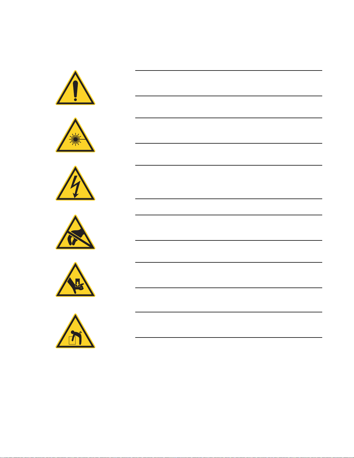
The signal words DANGER, WARNING, and CAUTION are
always emphasized with a safety symbol that indicates a special
hazard, regardless of the hazard level:
This symbol is intended to alert the operator to the presence of
important operating and maintenance instructions.
This symbol is intended to alert the operator to the danger of
exposure to hazardous visible and invisible laser radiation.
This symbol is intended to alert the operator to the presence of
dangerous voltages within the product enclosure that may be of
sufficient magnitude to constitute a risk of electric shock.
This symbol is intended to alert the operator to the danger of
Electro-Static Discharge (ESD) susceptibility.
This symbol is intended to alert the operator to the danger of
crushing injury.
This symbol is intended to alert the operator to the danger of a
lifting hazard.
xiii
Page 16

LabMax-TOP User Manual
Battery Compliance
Publication Updates
Firmware Updates
The batteries used in this product are in compliance with the EU
Directive 2006/66/EC (“EU Battery Directive”). For more information, refer to “Battery Directive” (p. 3-11).
T o view information that may have been added or changed since this
publication went to print, connect to www.Coherent.com.
To obtain the latest version of LabMax firmware:
1. Connect to www.Coherent.com.
2. Download the firmware to a USB flash drive.
To install the update:
1. Plug LabMax into an AC power source and then turn the meter
ON.
NOTICE!
Do not use battery power when installing a firmware update. A
power loss during the installation process will damage the meter,
which must then be returned to Coherent for repair.
2. Connect the flash drive to the USB flash drive connector on the
side panel of LabMax.
3. When the menu appears on the LCD, turn the Selection knob
to highlight the firmware name and then press the Enter/Set
button (Selection knob) to begin the installation.
4. When prompted on the installation menu, remove the flash
drive and press the Exit soft key to reboot LabMax.
xiv
Page 17
SECTION ONE: SAFETY
Carefully review the following safety information to avoid personal
injury and to prevent damage to this meter or any sensor connected
to it. This equipment contains no user-serviceable parts. For service
information, refer to “Obtaining Service” (p. 7-3).
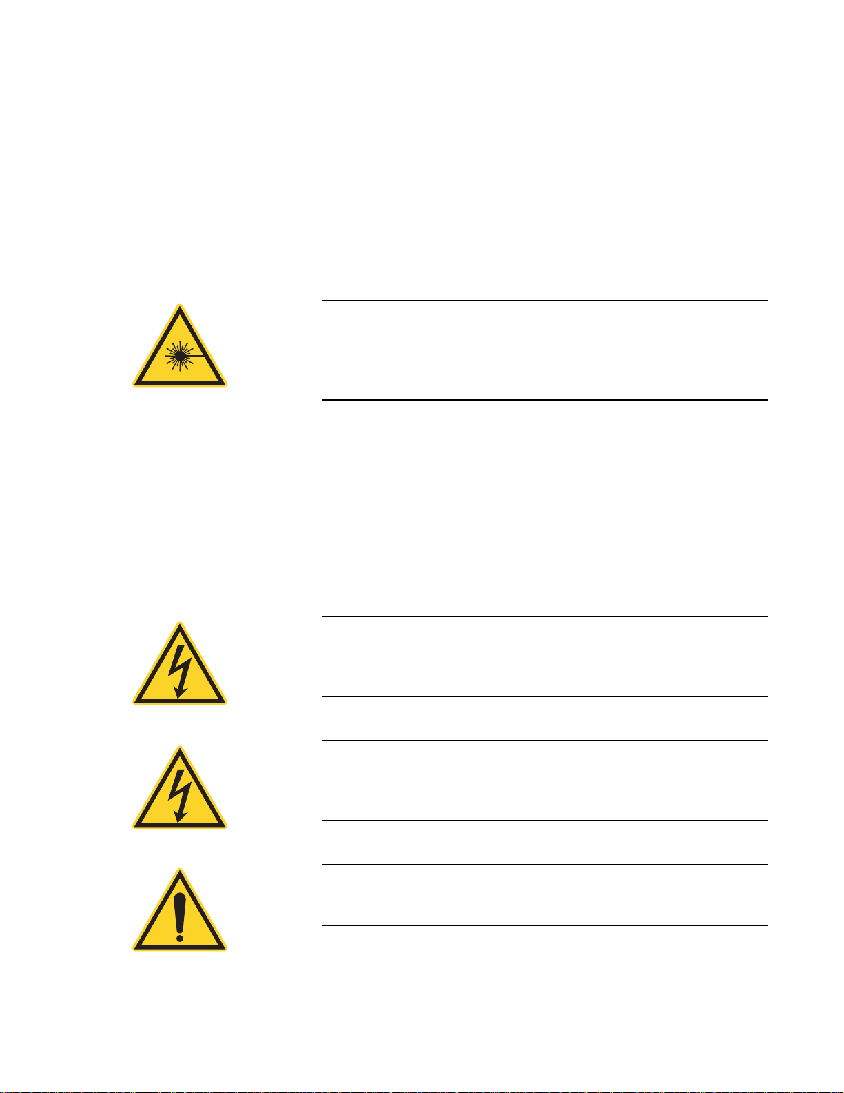
WARNING!
|The use and measuring of lasers is potentially dangerous. This
instrument operates over wavelengths that include non-visible
laser emissions.
Proper laser operating practice in accordance with manufacturer
recommendations is vital.
Safety
Eyewear and other personal protective equipment must be used in
accordance with applicable laws and regulations.
If in doubt of correct operating procedures, consult the laser manufacturer and your laser safety officer.
The equipment is not for use in critical medical environments.
WARNING!
Do not operate this instrument if its panels are removed or any
of the interior circuitry is exposed.
WARNING!
Do not operate this instrument in wet or damp conditions, or in
an explosive atmosphere.
NOTICE!
Operate this instrument only within the specified voltage range.
1 - 1
Page 18
LabMax-TOP User Manual
NOTICE!
Do not operate this instrument if there are suspected failures.
Refer damaged equipment to qualified Coherent service
personnel.
NOTICE!
Do not use battery power when installing a firmware update. A
power loss during the installation process will damage the meter,
which must then be returned to Coherent for repair.
Waste Electrical and Electronic Equipment (WEEE, 2002)
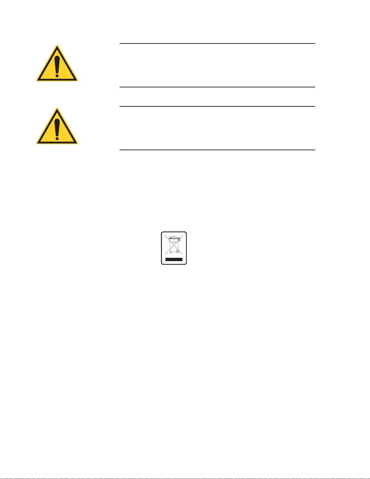
Figure 1-1. Waste Electrical and Electronic Equipment Label
Declaration of Conformity
The European Waste Electrical and Electronic Equipment (WEEE)
Directive (2002/96/EC) is represented by a crossed-out garbage
container label (see Figure 1-1). The purpose of this directive is to
minimize the disposal of WEEE as unsorted municipal waste and to
facilitate its separate collection.
Declaration of Conformity certificates are available upon request.
1 - 2
Page 19
SECTION TWO: QUICK START
This section presents “mini-tutorials” that explain how to connect a
sensor to your LabMax meter, begin taking measurements within
minutes, and save your data for later viewing.
• Measuring power with a thermopile or optical sensor
(page 2-2)
• Measuring energy with a pyroelectric sensor (page 2-3)
• Saving data to a file on the local drive (page 2-4)
• Moving a file to the USB flash drive (page 2-5)
For detailed information about each step of the procedures introduced in this section, refer to “Section Four: Operation” (p. 4-1).
Quick Start
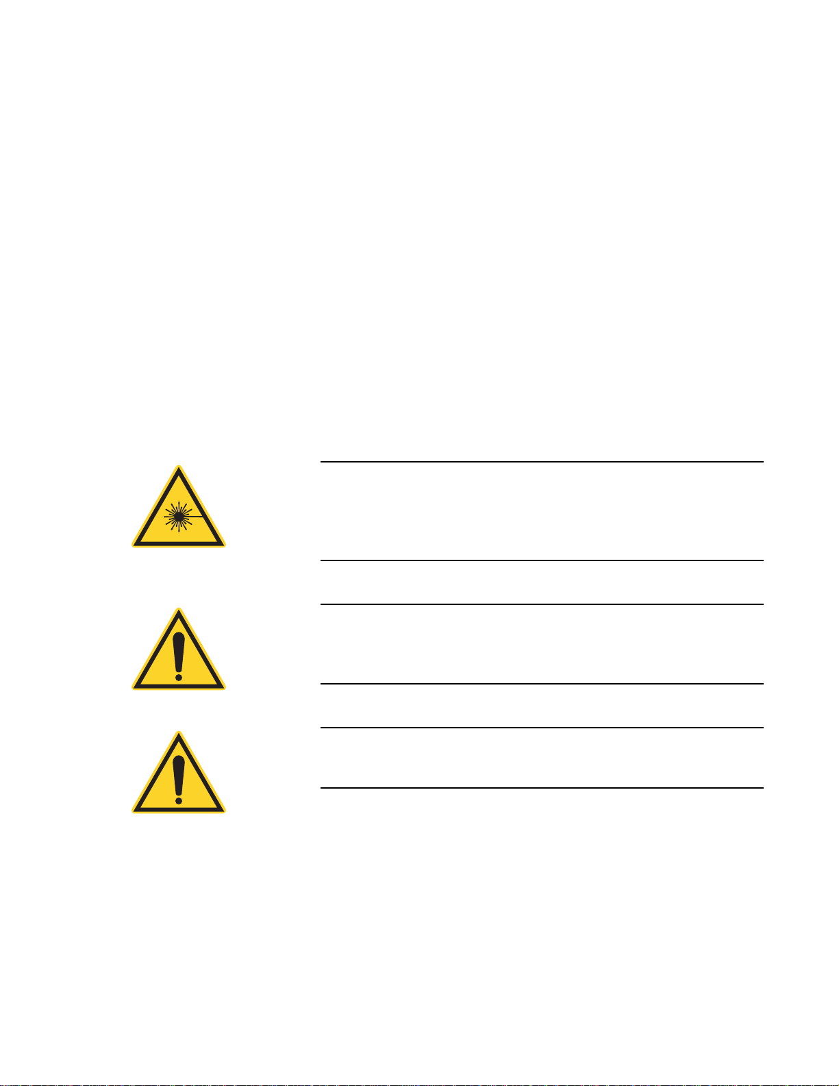
WARNING!
Follow all laser safety procedures. The laser must be blocked or
switched OFF before beginning any of the procedures described
in this section.
NOTICE!
Power to the LabMax meter must be OFF before beginning any
of the procedures described in this section.
NOTICE!
Do not exceed the power/energy density limits of the sensor.
2 - 1
Page 20
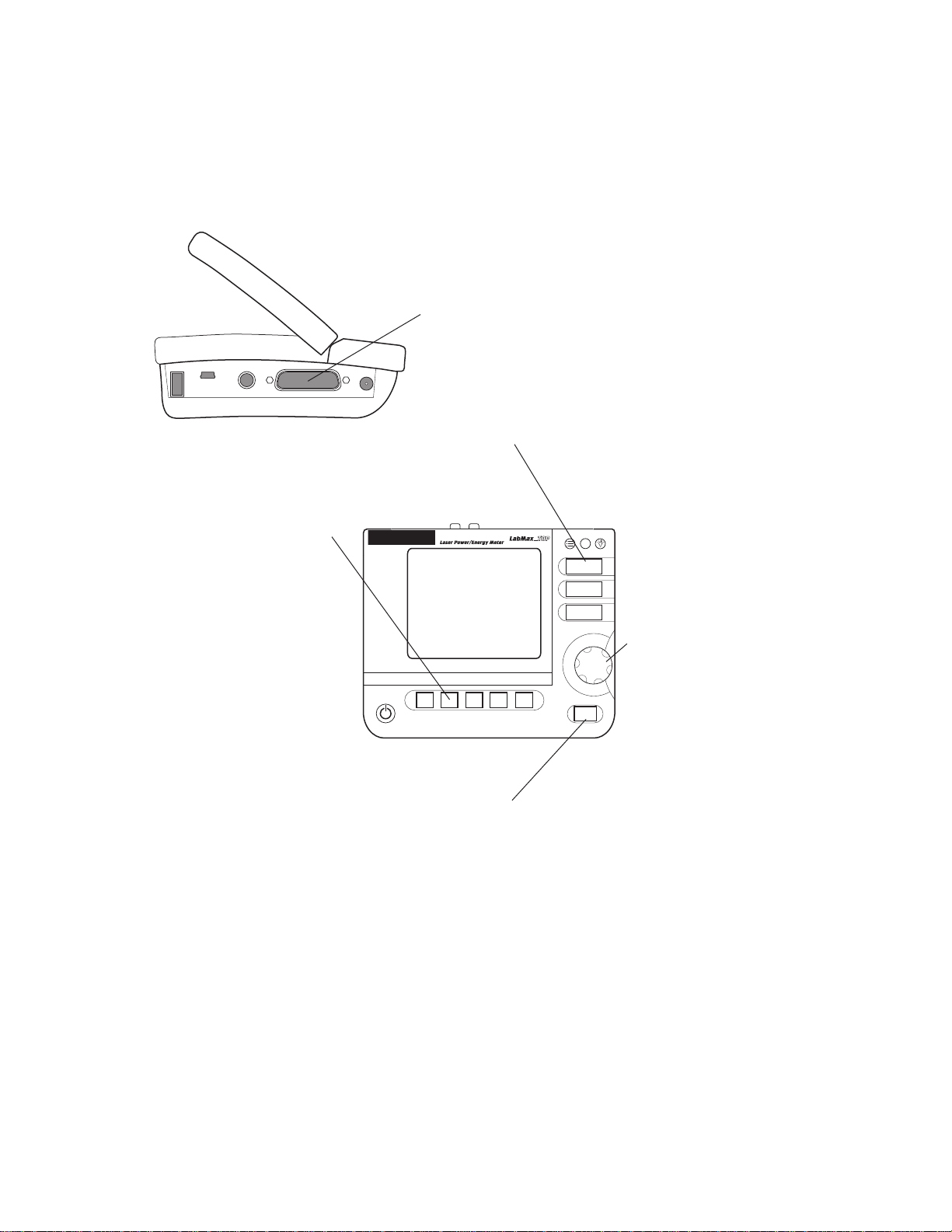
LabMax-TOP User Manual
?
MEASURE
TUNE
TREND
ZERO
X
Connect a thermopile or optical sensor to the
25-pin connector and turn the meter ON.
Note: Contact Coherent if the sensor has a
BNC plug and did not ship with a 25-pin
section of this manual for contact information).
Block the beam and then press the ZERO
button to set the baseline for the new
measurement.
[
Selection Knob
Z
Y
Press the MEASURE button.
Unblock the beam, take the measurement, and observe the result on the display.
Measuring Power With a Thermopile or Optical Sensor
Press the RANGE soft key
and then turn the Selection
knob to select the range.
Select Auto if you want
the meter to select the best
measurement range for you.
The tutorial describes how to take a power measurement using a
thermopile or optical sensor.
adapter (refer to the “Calibration and Warranty”
\
Figure 2-1. Quick Start: Measuring Power With a Thermopile or Optical Sensor
2 - 2
Page 21
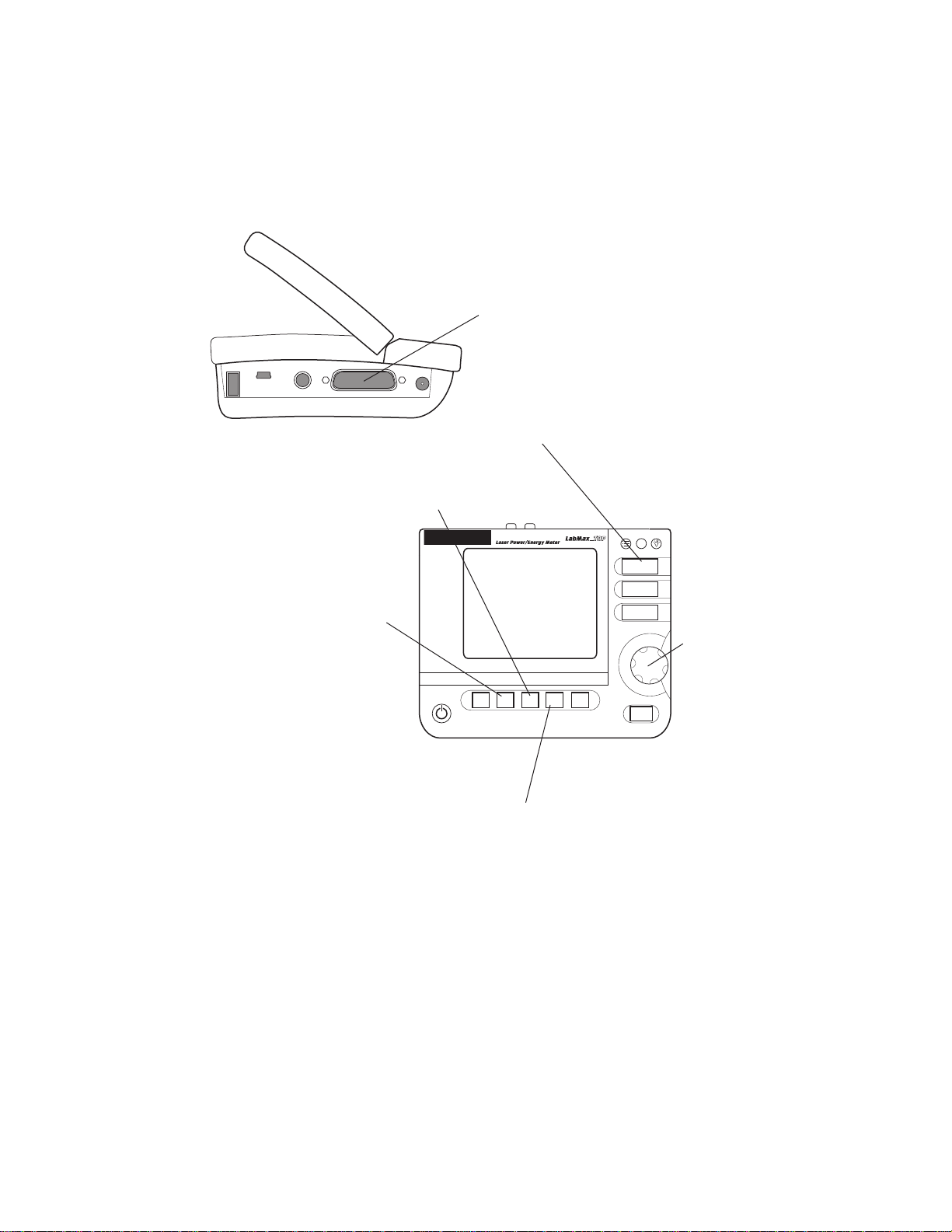
Quick Start
?
MEASURE
TUNE
TREND
ZERO
X
Connect a pyroelectric sensor to the 25-pin
connector and turn the meter ON.
Note: Contact Coherent if the sensor has a
BNC plug and did not ship with a 25-pin
adapter (refer to the “Calibration and Warranty”
section for contact information).
Press the RANGE soft key
and then turn the Selection
knob to select the range.
Note: Auto range is not
available for this type of
sensor.
[
Press the TRIG LEV soft key and then turn the
Selection knob to adjust the trigger threshold.
Make sure the trigger threshold is set
below
the energy level you plan to measure and
above
the level at which the system triggers on noise.
\
Selection Knob
If Watts mode is currently selected,
toggle the UNITS soft key to select
Joules mode.
Z
Y
Press the MEASURE button.
Take the measurement and observe the result on the display.
]
Measuring Energy With a Pyroelectric Sensor
This tutorial shows how to take an energy measurement using a
pyroelectric sensor.
Figure 2-2. Quick Start: Measuring Energy With a Pyroelectric Sensor
2 - 3
Page 22
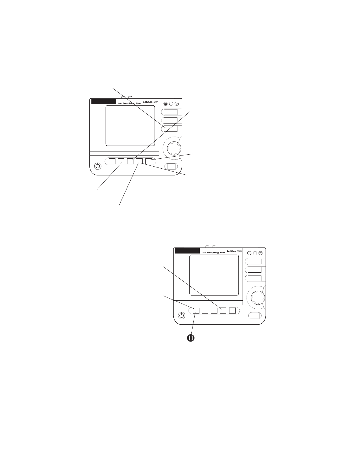
LabMax-TOP User Manual
?
MEASURE
TUNE
TREND
ZERO
?
MEASURE
TUNE
TREND
ZERO
\
want to save to file.
[
Press the TREND SETUP soft key.
^
Press the SAVE soft key.
]
_
Create a file name on the TREND: Name Log File screen.
`
Press the SAVE soft key.
a
Press the START soft key.
When data collection is complete,
press the RESET soft key.
Y
and navigate to the /loc drive.
Note: The drive (/loc or /usb) that
opens in FILE MANAGER defaults
to the last drive accessed during
the previous session, or to the
/loc drive if no USB flash drive is
attached to the meter.
Z
Press the EXIT soft key.
Saving Data to a File on the Local Drive
Press the TREND button.
Press the CREATE
FILE soft key.
In this tutorial you will learn how to create—and save data to—a file
that’ s stored on the local drive (/loc). The tutorial on page 2-5 shows
how to move a file to the USB flash drive. You can also save data
directly to the USB flash drive by navigating to the USB drive in
Step 2, in the following illustration.
X
Set the Duration value to the sample size you
Press the FILE MANAGER soft key
Data is now saved in the file created in step 8.
Figure 2-3. Quick Start: Saving Data to a File on the Local Drive
2 - 4
Page 23
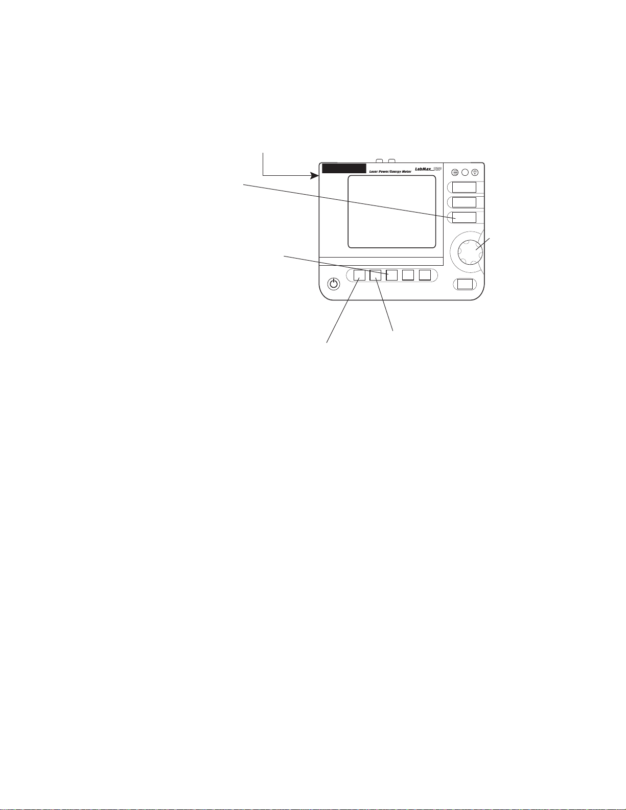
Quick Start
?
MEASURE
TUNE
TREND
ZERO
X
[
Press the COPY MOVE soft key.
The file selected in step 4 has been moved to
Press the ENTER/Set button to dismiss the confirmation dialog box.
]
/
Y
Z
\
Navigate to a folder using the
then press the MOVE soft key.
^
Selection Knob
Moving a File to the USB Flash Drive
Attach a USB flash drive to the
connector on the side panel.
Press the TREND button.
Press the FILE MANAGER soft
key and navigate to the /loc drive.
Note: The drive (/loc or /usb) that
opens in FILE MANAGER defaults
to the last drive accessed during
the previous session, or to the
loc drive if no USB flash drive is
attached to the meter.
Highlight the file you want to move.
This tutorial shows how to move a file from the local drive (/loc) to
the USB flash drive (/usb) connected to LabMax.
Selection knob, if you wish, and
the /usb drive and removed from the /loc drive.
Figure 2-4. Quick Start: Moving a File to the USB Flash Drive
2 - 5
Page 24

LabMax-TOP User Manual
2 - 6
Page 25

SECTION THREE: DESCRIPTION
Thank you for purchasing the LabMax™-TOP Laser Power/Energy
Meter—a versatile, easy-to-use, single-channel power/energy meter
designed for anyone who needs to measure and analyze laser output.
In this section:
• Product overview (this page)
• Product features (page 3-2)
• Menu layout (page 3-3)
• Front panel (page 3-4)
• Side panel (page 3-6)
• Rear panel (page 3-7)
Description
Product Overview
• Battery indicators (page 3-8)
• Dip Switch (OEM mode) (page 3-10)
• Battery pack replacement (page 3-11)
• AC adapter (page 3-12)
The LabMax-TOP Laser Power/Energy Meter meets your needs in
new ways via onboard data logging as well as support for logging
data directly to a USB flash drive. It also offers enhanced data analysis and statistics, and a form factor that allows flexible positioning
and viewing angles so it can be used in areas with limited bench
space. LabMax is directly compatible with most Coherent thermal,
pyroelectric, and semiconductor sensors (with no need for adapters)
and displays beam position for quick and accurate setup. Performance is enhanced in the form of low noise pulse energy measurement and high resolution power measurement.
3 - 1
Page 26

LabMax-TOP User Manual
Product Features
Specific features of your LabMax meter include:
• Compatible with LM-, PM-, and PS- model thermopile
sensors, and OP-2 and LM-2 model optical sensors. No
adapters required.
• Displays beam position with LM-model sensors
• Supports 5-digit resolution with thermopile and optical sensors
(user-selectable).
• Pyroelectric:
• Measures energy to 10000 pps and captures every pulse
to 1000 pps with J-model and EnergyMax sensors.
Streams data over USB to 1000 Hz. Also measures rep.
rate and calculates average power. (LabMax is not
compatible with the legacy LM-P model energy sensors.)
• Large, graphical display with backlight. Ergonomic interface
with easily accessible buttons for all features and modes. Flexible positioning of the display allows viewing from many
angles.
• Digital tuning indicators - horizontal bar and trend chart
formats with peak indicators.
• Onboard statistics (mean, minimum, maximum, standard devi-
ation, range, three stability parameters, dose, and missed
pulses). Display up to six user-selectable statistical parameters
at a time.
• Data logging can be performed directly to a USB flash drive,
or up to 400,000 points can be retained onboard the meter . The
meter has a file management system that allows naming and
renaming files, auto increments file names for repetitive
logging events, supports folder creation and renaming, and
transfers files and folders from onboard memory to USB flash
drive.
• USB, RS-232, and GPIB (LabMax-TOP w/GPIB model only)
computer interfaces with full host control and drivers for both
VisualBasic and LabVIEW™ programmers. Plug-and-play
applications software is also supplied standard, along with
USB and RS-232 cables (an optional GPIB cable is also available through Coherent).
• Analog output with user-selectable full-scale voltage of 1, 2 or
4V. RCA-to-BNC converter included (standard).
• External trigger input with user-selectable slope and trigger
delay.
3 - 2
Page 27
Description
SETUP
SETUP: Manage
Configs
SETUP: Save
Current Config
HELP
HELP: All Topics
(context-sensitive)
HELP:
MEASURE
STATS
STATS: Setup
STATS: Change
POSITION STABILITY
(thermopile quads only)
TREND
TREND: Name
Log File
TREND: File
Manager
TREND: Setup
(no submenus)
TUNE
• Field-upgradeable meter internal software and operating
system, with updates available on the Coherent website or
e-mailed directly to the user. This feature ensures that you
always have the latest LabMax features.
• Li-ion battery powered (4400 mAh pack standard), as well as
the ability to operate with an AC power adapter (PSE and UL
approved). Meter contains a smart charging circuit onboard to
charge the rechargeable battery pack and the display has a
battery level indicator. AC power adapter and cord are
included.
• LabVIEW Instrument Driver that can be used with USB,
RS-232, or GPIB interfaces.
• Applications software that allows you to plug the meter into
your PC and immediately analyze data and log it to a file. The
software is contained on the CD that ships with the meter and
will also be available on our website as a free download.
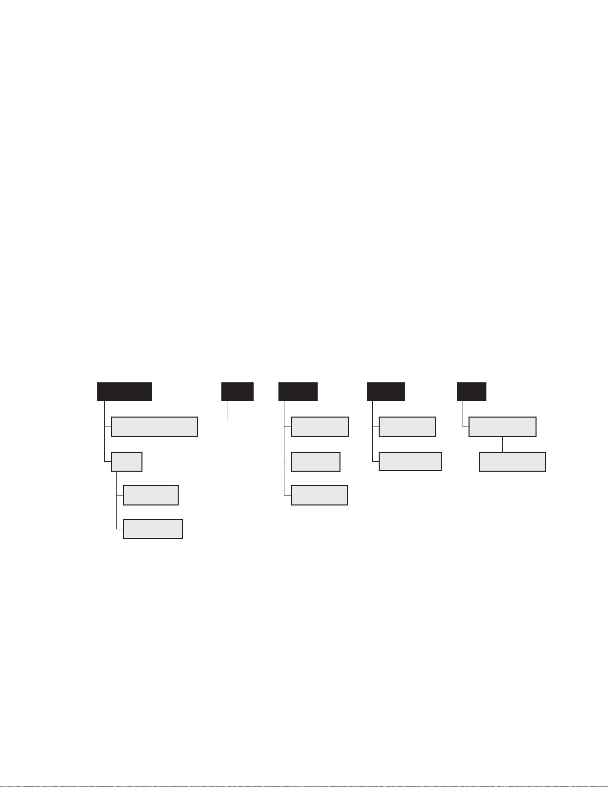
Menu Layout
Stats
The following chart graphically depicts the LabMax menu organization.
Figure 3-1. Menu Organization
3 - 3
Page 28
LabMax-TOP User Manual
?
MEASURE
TUNE
TREND
ZERO
Soft Keys
LCD
Zero Button
Measure Button
Tune Button
Trend Button
Selection Knob
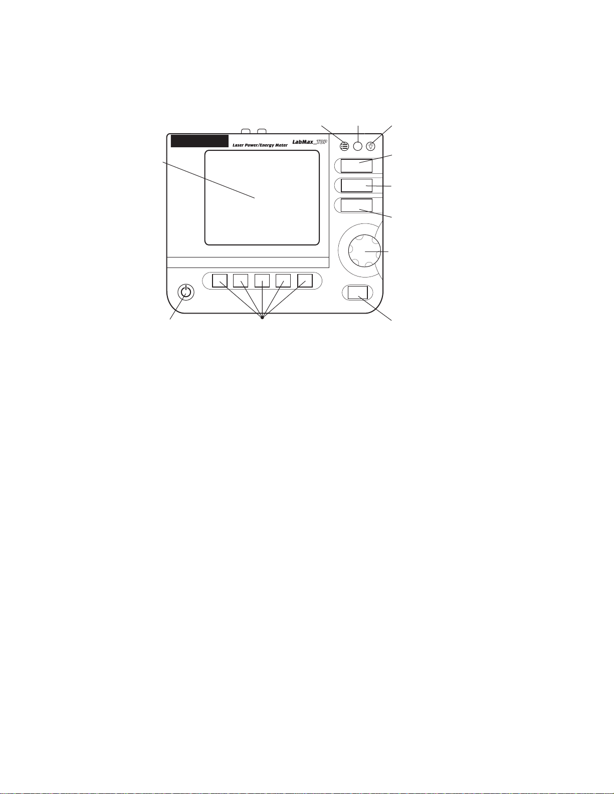
Front Panel
Power On/Off
The front panel (shown in Figure 3-2) includes a large liquid crystal
display (LCD), as well as buttons, a Selection knob, and soft keys
that are used to enter parameters, select modes, and change ranges.
Setup Button Help Button Backlight Button
(Enter/Set Button)
Button
Buttons
Figure 3-2. Front Panel
LabMax has the following buttons (refer to Figure 3-2 for button
locations):
• SETUP
• HELP
• BACKLIGHT
• MEASURE
• TUNE
• TREND
• ZERO
• Power On/Off
• Selection knob (which also functions as the Enter/Set button
For detailed information about each of the buttons, refer to “Section
Four: Operation” (p. 4-1).
when pressed, rather than turned)
3 - 4
Page 29

Description
Soft Keys
Power On/Off Button
The five soft keys—just below the LCD—are used for three main
functions:
• Navigating to a different screen. Examples: POSITION
STABILITY and TREND SETUP.
• Performing an action. Examples: START and RESET.
• Making a selection from a list of possible choices. Examples:
RANGE and UNITS.
For detailed information about soft keys, refer to “Section Four:
Operation” (p. 4-1). T o learn how to change a value, refer to “Selection Knob” (p. 3-5).
If a sensor is connected to the meter when it is turned on,
the meter defaults to the last mode (MEASURE, TUNE,
TREND, or SETUP) used with that specific type of
sensor (thermopile, optical, or pyroelectric). If the wavelength of the new sensor is out of range of the previously-selected
wavelength for the sensor typed attached, the meter automatically
switches to the calibration wavelength for that sensor.
Selection Knob
A “Searching for sensor” error message will appear on the LCD if
the meter is turned on without a sensor connected to it.—see “Meter
and Sensor Errors” (p. B-1) for a complete listing and description of
all error messages.
To change a value, first turn the Selection knob to select
a specific value, and then press the Selection knob
(which also functions as an Enter/Set button when
pressed, rather than turned) to save the value.
3 - 5
Page 30
LabMax-TOP User Manual
Side Panel
USB Flash Drive
USB Flash Drive
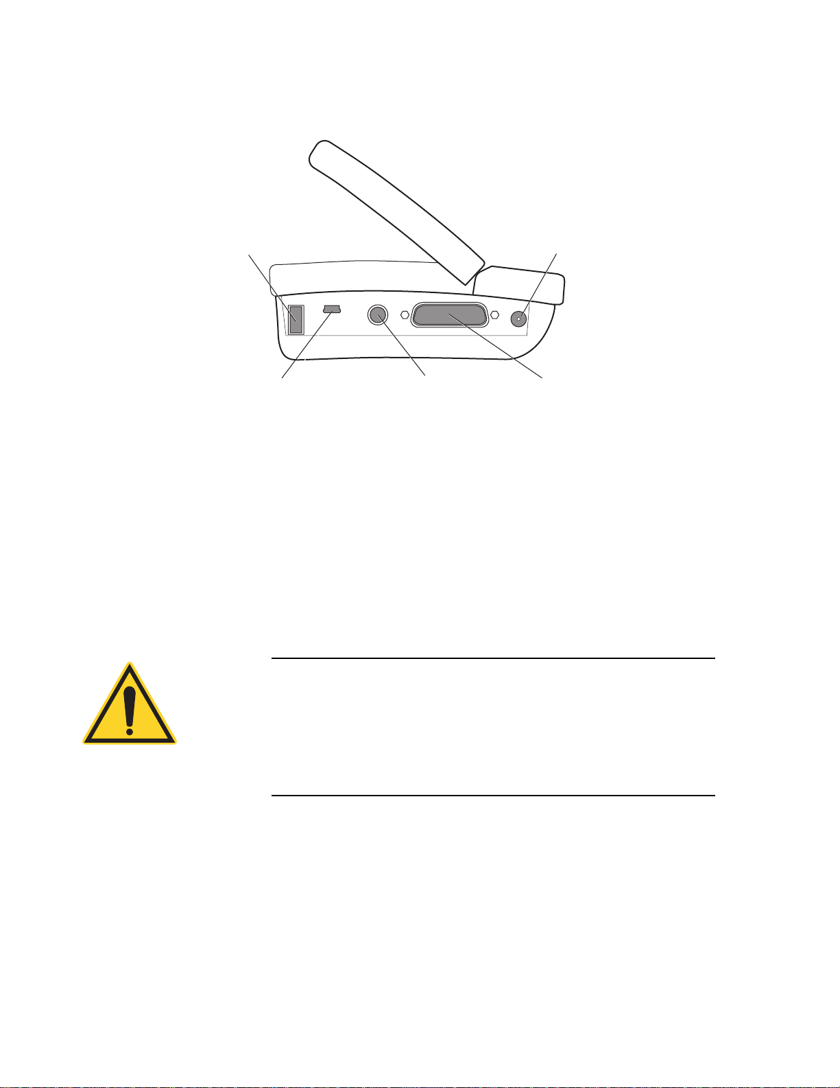
Figure 3-3 shows the location of the LabMax connectors on the side
panel. Each of these connectors is discussed, below.
Power Jack
RS-232
Figure 3-3. Side Panel Connectors
This is an input connector for a USB (FAT16) flash drive.
Sensor Mini-USB (PC Interface)
Connector
Mini-USB Connector
RS-232 Connector
Attaching the cable—shipped with the meter—to this mini-USB
connector allows communication between LabMax and a computer
that has a USB interface.
NOTICE!
Install the LabMax software before physically connecting the
meter to the computer . For information abo ut installing the software , refer t o the LabMax PC Software Installation and Quick
St art Guide (1175379) inside the CD case that shipped with your
product.
This is an RS-232, female, miniature 6-pin DIN. For a list of pin
assignments, refer to Table A-2 (p. A-2).
3 - 6
Page 31
Description
Cable Locking Sheath
OPEN
GPIB
EXT
TRIG
ANALOG
OUT
Analog Out Ext Trig
GPIB
(LabMax-TOP w/GPIB
model only)
To connect the RS-232 cable to the meter:
1. Hold the cable locking sheath in the open position:
2. Slide the cable into the RS-232 connector on the side of the
meter.
3. Release the cable locking sheath to lock the cable in place.
Sensor Connector
Power Jack Connector
Rear Panel
Use this connection to attach a Coherent thermopile, optical, or
pyroelectric sensor to LabMax.
Connect the power cord—shipped with the meter—to this
connector.
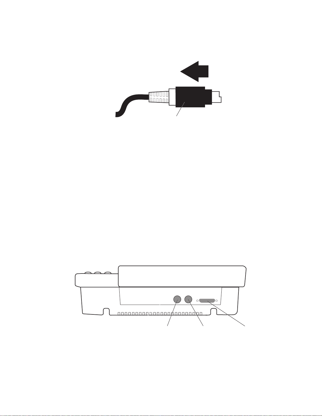
The following figure shows the location of the LabMax connectors
on the rear panel. Each of these connectors is discussed, below.
Figure 3-4. Rear Panel Connectors
3 - 7
Page 32

LabMax-TOP User Manual
Ext Trig Connector
Analog Out Connector
GPIB Connector
Battery Indicators
(Trigger In) Attach an external trigger source to this connection.
This source is used if external triggering is specified. For more infor mation about trigger settings, refer to “Trigger” (p. 4-58).
When power is on, the Analog Out connector outputs a voltage
proportional to the current laser measurement with respect to the
measurement range. The output voltage is zero (0) volts when the
measured energy or power is zero (0) or less. The output voltage is
the full-scale output voltage when the measured energy or power is
full-scale or overranged. The full-scale output voltage (1, 2, or 4V)
is selected in the SETUP screen or via the host interface. Factory
default full-scale output voltage is 2V.
This is an IEEE-488 computer interface found on the LabMax-TOP
w/GPIB model.
This section discusses three indicators that provide information on
the status of the internal battery . These indicators appear in the upper
left corner of the LCD.
The Battery Life indicator visually represents the
percentage of remaining battery life (refer to Table 3-1).
This indicator only appears on the screen when a battery
is installed in the meter.
NOTICE!
The Battery Life indicator will begin flashing shortly before the
battery is completely discharged. To avoid loss of data, immediately either save the current information to a file, or connect AC
power to the meter.
Table 3-1. Battery Life Indicator
Number of
Visible Bars
5 81 to 100%
4 61 to 80%
3 41 to 60%
2 21 to 40%
1 11 to 20%
0 0 to 10%
Remaining Battery
Life
3 - 8
Page 33
Battery Charging Procedure
Description
The Charging indicator signals that the battery is
currently being charged. It only appears on the screen
when the meter is running on AC power and the installed
battery has less than 100% charge. Once the battery is
completely charged, the Charging indicator disappears.
The Charging Malfunction indicator only appears when
there is something wrong with the battery charging
process. To attempt to solve the problem, begin by
removing the battery and then re-attaching it. Then
unplug the AC power source from the meter and then plug it back in.
If this does not clear the error, fully drain the battery and rechar ge it
(refer to “Battery Charging Procedure” (p. 3-9) for information
about discharging and recharging the battery). If the Charging
Malfunction indicator continues to display, call Coherent for assistance. Refer to Table 7-1 (p. 7-4) for contact information.
NOTICE!
To achieve greater battery fuel gauge accuracy, complete the
following procedure. This procedure must be repeated whenever
a new battery pack is installed (including when you first receive the
meter) and can be repeated at any time to reset the fuel gauge
registers.
1. Install the battery pack into LabMax (in the case of a new
meter, the battery pack comes already installed). Refer to
“Battery Pack Replacement” (p. 3-11) to see how to attach the
battery connector to the meter.
2. Fully-charge the battery pack by running the meter on AC
power for at least eight hours.
3. Fully-discharge the battery pack by unplugging LabMax from
the AC source and then running the meter using only battery
power . Let the meter run until it automatically shuts off (which
indicates a dead battery).
3 - 9
Page 34
LabMax-TOP User Manual
Battery Compartment
Dip Switch is
visible here
4. Fully-charge the battery pack again (> 8 hr.).
It can take up to one minute for LabMax to update the Battery
Charge indicator after the installation of a new battery or after
attaching an AC power adapter.
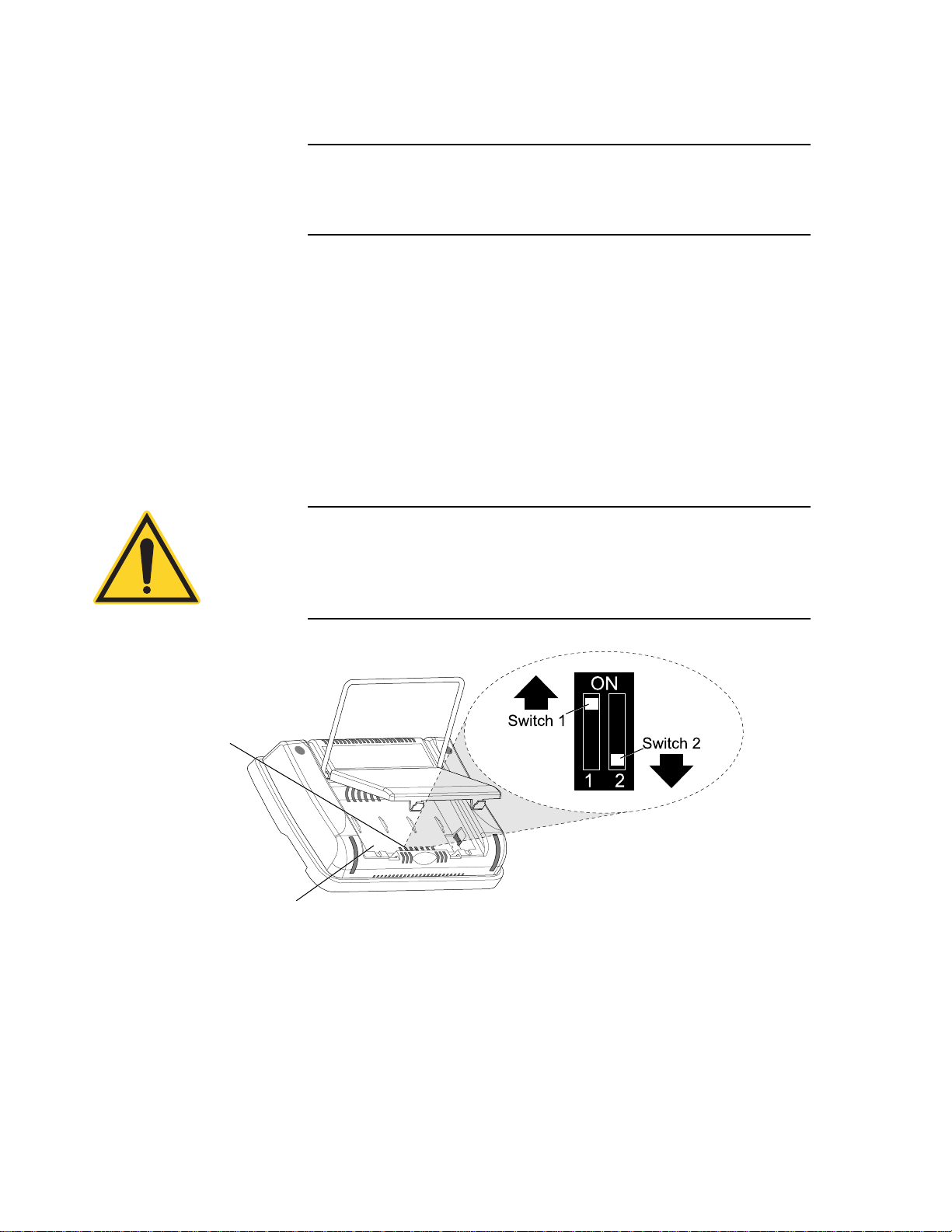
Dip Switch (OEM Mode)
Setting the Dip switch to OEM mode ensures that if power is lost
while the meter is in use, it will automatically turn back on again
when power is restored. The benefit of this mode is that, following
a power loss, remote installations can communicate with the meter
without having to manually recycle instrument power.
T o activate OEM mode, move Switch 1 on the Dip switch to the ON
position (see the following figure).
NOTICE!
To avoid prematurely draining the onboard battery (which
could result in erratic meter readings), leave Switch 2 in the
down (OFF) position.
Figure 3-5. Dip Switch (OEM Mode)
3 - 10
Page 35
Description
Battery Pack Replacement
Battery Directive
Figure 3-6 (p. 3-12) illustrates how to replace the LabMax standard
battery pack. T o review battery specifications, refer to “Appendix A:
Specifications” (p. A-1).
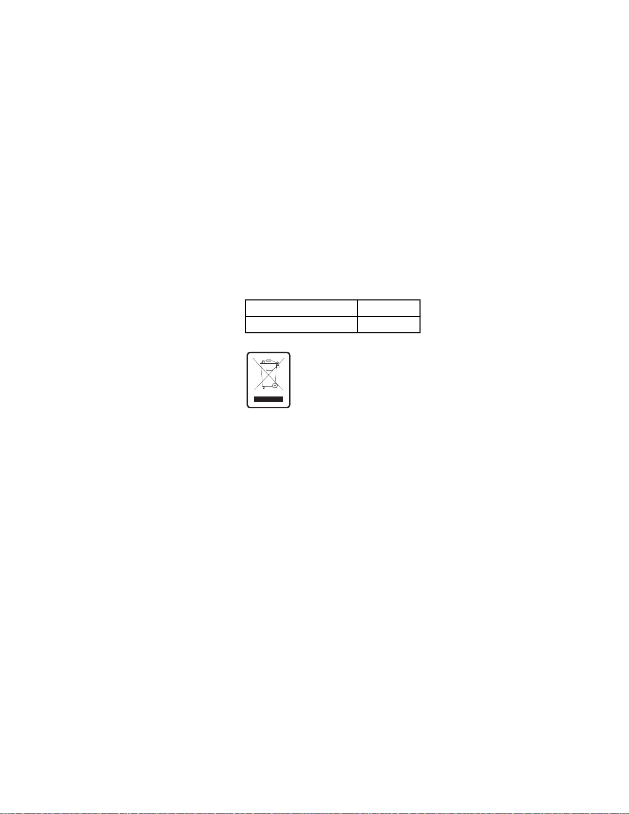
The batteries used in this product are in compliance with the EU
Directive 2006/66/EC (“EU Battery Directive”).
Additionally , the Lithium-Ion rechar geable battery pack us ed in this
product has been evaluated and tested to ensure compliance with the
Fourth Revised Edition of the UN Manual of Tests and Criteria, Sec
38.3, Lithium Batteries (ST/SC/AC.10/11/Rev.4) - more commonly
known as the UN T1-T8 Transportation tests, and has been found to
comply with the stated criteria.
Table 3-2. Batteries Contained in this Product
Description Type
4400 mAH battery pack Lithium Ion
Dispose of batteries according to local regulations. Do
not dispose as normal waste. Consult your local waste
authorities for guidance.
3 - 11
Page 36

LabMax-TOP User Manual
Lay the meter face down on a flat surface and open the stand.
Y
Open the battery cover.
Z
Carefully lift the battery pack to expose
the battery connector. Be careful to not
pull the wires out of the battery connector.
[
Push down on the tab and pull the
battery connector out of the socket.
Battery Connector
\
Remove the battery pack. When installing a new battery
pack, make sure the battery connector is pressed back
into the socket and the wires are situated under
pack.
Tab
X
Figure 3-6. Battery Pack Replacement
AC Adapter
Using an AC adapter prolongs battery life. LabMax automatically
senses when an adapter is being used.
the battery
3 - 12
Page 37

SECTION FOUR: OPERATION
MEASURE
In this section:
• Units (this page)
• MEASURE (this page)
• TUNE (page 4-25)
• TREND (page 4-28)
• ZERO (page 4-44)
• SETUP (page 4-45)
• HELP (page 4-73)
• BACKLIGHT (page 4-74)
Operation
Units
MEASURE
Measurement units are expressed in terms listed in the following
table:
Table 4-1. Joules and Watts Units
a
Joules
pJ (picojoules) pW (picowatts)
nJ (nanojoules) nW (nanowatts)
µJ (microjoules) µW (microwatts)
mJ (millijoules) mW (milliwatts)
J (joules) W (watts)
kW (kilowatts)
a. When area correction is en-
abled, all units are expressed
in terms of per cm
words, the /cm
ways appended to the units.
2
2
suffix is al-
a
Watts
. In other
The MEASURE mode provides three primary functions:
Measure Power, Measure Energy, and Statistics. Each of
these functions are discussed in detail, below.
4 - 1
Page 38
LabMax-TOP User Manual
MEASURE POWER
RANGE
Auto
STATS
Wavelength: nm Gain: Smoothing:
514 OFF OFF
22.1 W
UNITS
Watts
Measurement Display and Range Selection
Measure Power
The graphical display update rate for numeric measurement is three
times per second.
Measurement range is selected in decade steps. Range selection is
dependent on the sensor type and characteristics, as well as
user-determined measurement settings.
LabMax uses the “3’s” Rule—a display formatting rule in which the
display value is not allowed to exceed 3, 30, or 300, depending on
where the decimal point falls, with the decimal point located in a
fixed position, as determined by the current range. Typically if a
reading exceeds the “3’s” limit, the instrument is over-ranged or, in
the case of Auto Ranging, the instrument will automatically range
up.
Over-ranging refers to a meter setup condition in which the sensor
output signal is greater than the maximum allowable level for the
selected range. OVR appearing on the display signifies an
over-range condition. Over-ranging generates invalid data.
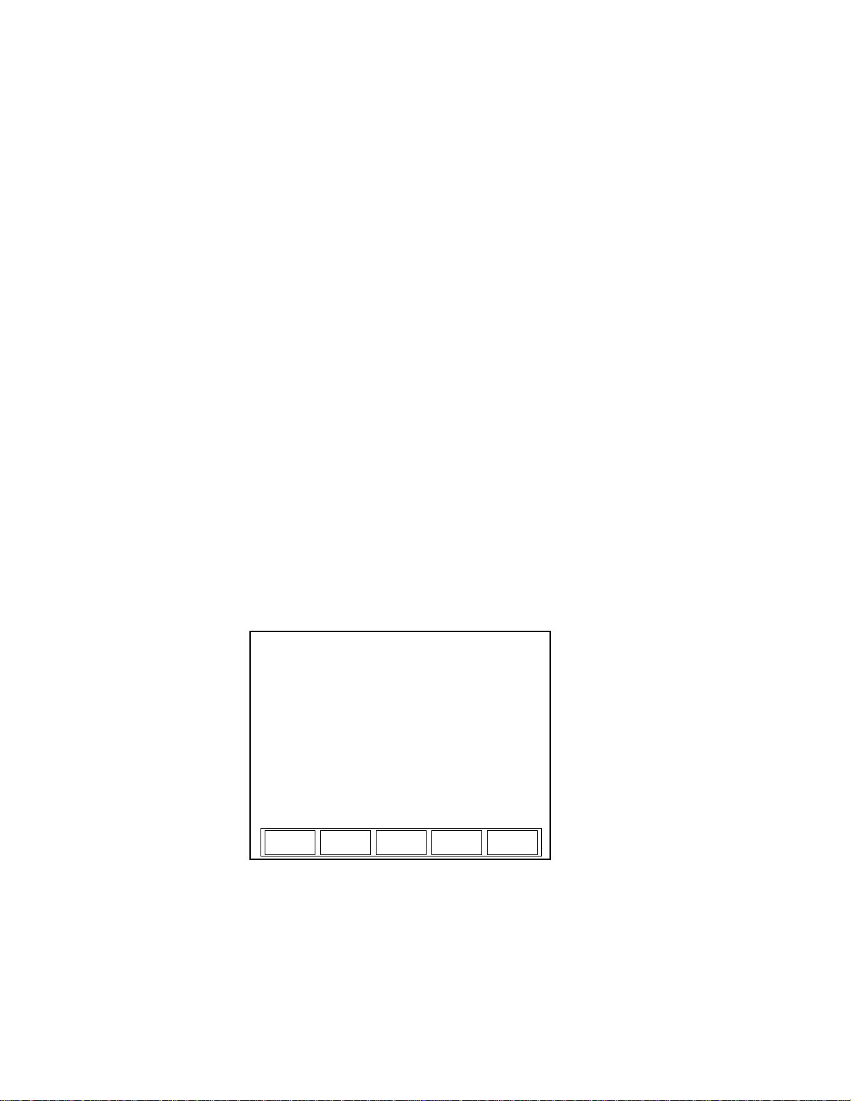
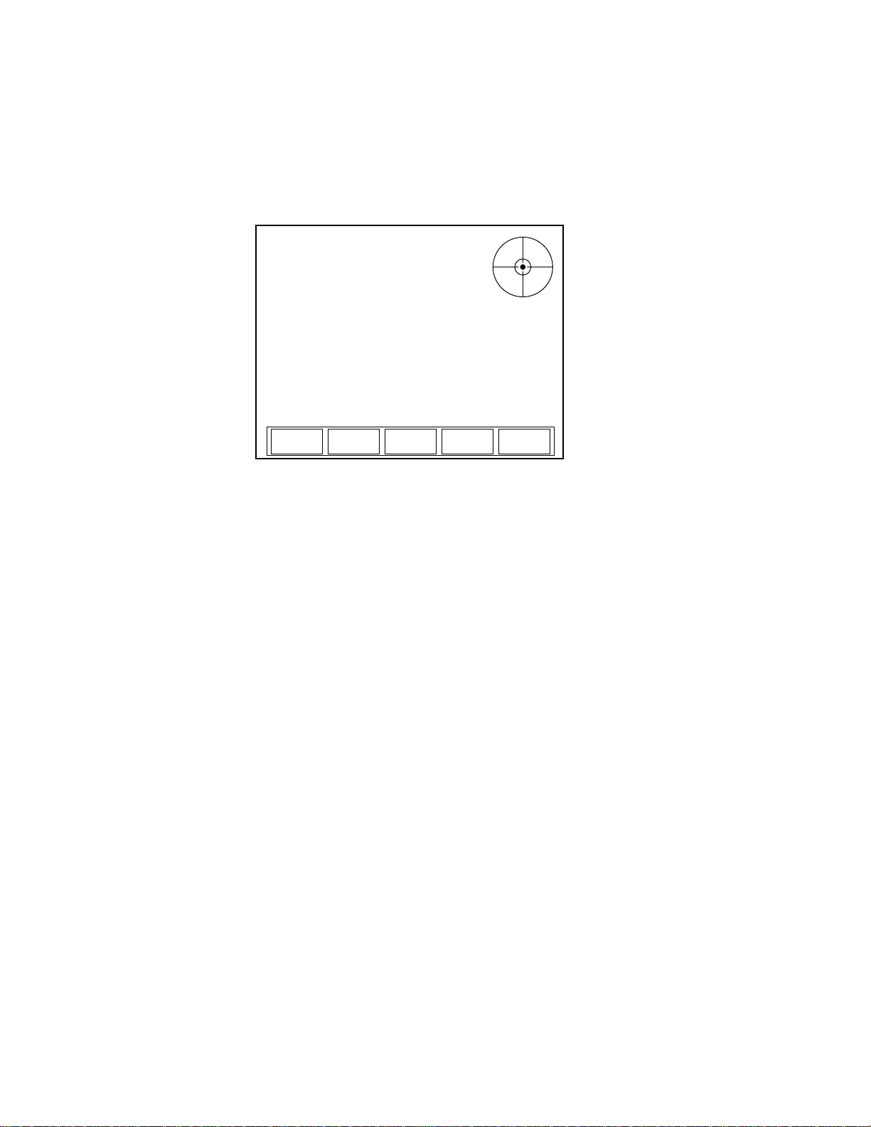
Thermopile Sensors Figure 4-1 shows an example of how the MEASURE POWER
screen looks when a thermopile sensor is connected to the
meter—for thermopile quad sensors, refer to “Thermopile Quad
Sensors” (p. 4-4):
Figure 4-1. MEASURE POWER: Thermopile Sensors
This screen contains the live reading and also shows the following
indicators: Wavelength, Gain, and Smoothing. Note that Figure 4-1
shows an example screen with Area Correction turned OFF. With
4 - 2
Page 39
Operation
Area Correction turned ON, the screen looks slightly different. A
summary of indicator behavior is provided in “Appendix C:
Onscreen Indicators” (p. C-1).
Soft Keys
There are three soft keys on this screen: RANGE, UNITS, and
STATS.
RANGE
• Available values (thermopile and optical sensors): Auto
(factory default) and the allowable ranges for the attached
sensor.
• Available values (pyroelectric sensors): Sensor-dependent.
To adjust the range:
1. Press the RANGE soft key.
2. Turn the Selection knob to change the range value.
3. When the desired value appears, press the RANGE soft key (or
the ENTER/SET button) to lock in the RANGE value.
UNITS
Pressing the UNITS soft key toggles the measurement units between
Watts and Joules.
STATS
Refer to “Statistics” (p. 4-15) for information about the STATS
menu.
Over-Temperature Condition
(thermopile sensors only) Whenever the meter detects a sensor
over-temperature condition, a Sensor Over Temp dialog message
appears on the screen. This message does not appear unless a sensor
over-temperature condition exists.
NOTICE!
If a Sensor Over Temp message appears on the screen, turn the
laser off immediately and let the sensor cool down.
4 - 3
Page 40
LabMax-TOP User Manual
MEASURE POWER
RANGE
Auto
STATS
Wavelength: Gain: Smoothing:
514 nm OFF OFF
9.4 W
POSITION
STABILITY
TARGET
Small
UNITS
Watts
Thermopile Quad Sensors
Figure 4-2. MEASURE POWER: Thermopile Quad Sensors
Figure 4-2 shows an example of how the MEASURE POWER
screen looks when a thermopile quad sensor is connected to the
meter. In addition to the live display, there is a positional target that
is used to make sure the beam is aligned to the center of the sensor
before taking a measurement. The outer edge of the bulls eye target
represents the outer edge of the sensor's active area.
This screen contains the live reading and also shows the following
indicators: Wavelength, Gain, and Smoothing. A summary of indicator behavior is provided in “Appendix C: Onscreen Indicators”
(p. C-1).
Soft Keys
There are five soft keys on this screen: TARGET, RANGE, UNITS,
POSITION STABILITY, and STATS.
TARGET
Available values: Small and Large.
To adjust the size of the target, toggle the TARGET soft key.
RANGE
• Available values (thermopile and optical sensors): Auto
(factory default) and the allowable ranges for the attached
sensor.
• Available values (pyroelectric sensors): Sensor-dependent.
4 - 4
Page 41

Operation
MEASURE POWER
RANGE
Auto
STATS
Wavelength:
532 nm
Gain:
OFF
Smoothing:
OFF
Offset:
---
21 nW
To adjust the range:
1. Press the RANGE soft key.
2. Turn the Selection knob to change the range value.
3. When the desired value appears, press the RANGE soft key (or
the ENTER/SET button) to lock in the RANGE value.
UNITS
Pressing the UNITS soft key toggles the measurement units between
Watts and Joules.
POSITION STABILITY
Refer to “POSITION STABILITY” (p. 4-23).
STATS
Refer to “Statistics” (p. 4-15) for information about the STATS
menu.
Optical Sensors Figure 4-3 shows an example of how the MEASURE POWER
screen looks when an optical sensor is connected to the meter:
Figure 4-3. MEASURE POWER: Optical Sensors
This screen contains the live reading and also shows the following
indicators: W avelength, Offset, Gain, and Smoothing. A summary of
indicator behavior is provided in “Appendix C: Onscreen Indicators” (p. C-1).
Soft Keys
There are two soft keys on this screen: RANGE and STATS.
4 - 5
Page 42

LabMax-TOP User Manual
RANGE
• Available values (thermopile and optical sensors): Auto
(factory default) and the allowable ranges for the attached
sensor.
• Available values (pyroelectric sensors): Sensor-dependent.
To adjust the range:
1. Press the RANGE soft key.
2. Turn the Selection knob to change the range value.
3. When the desired value appears, press the RANGE soft key (or
the ENTER/SET button) to lock in the RANGE value.
STATS
Refer to “Statistics” (p. 4-15) for information about the STATS
menu.
Measure Energy
Pulsed Thermopile Joules Mode
(for long-pulsed lasers only) When a thermopile sensor is attached,
the meter has the capability of measuring energy from a finite duration laser pulse, or from a series of finite duration laser pulses.
(Thermopile sensors are typically used to measure laser power and
have an extremely slow response time relative to the pulse width of
the laser used to generate the power signal.)
4 - 6
Page 43
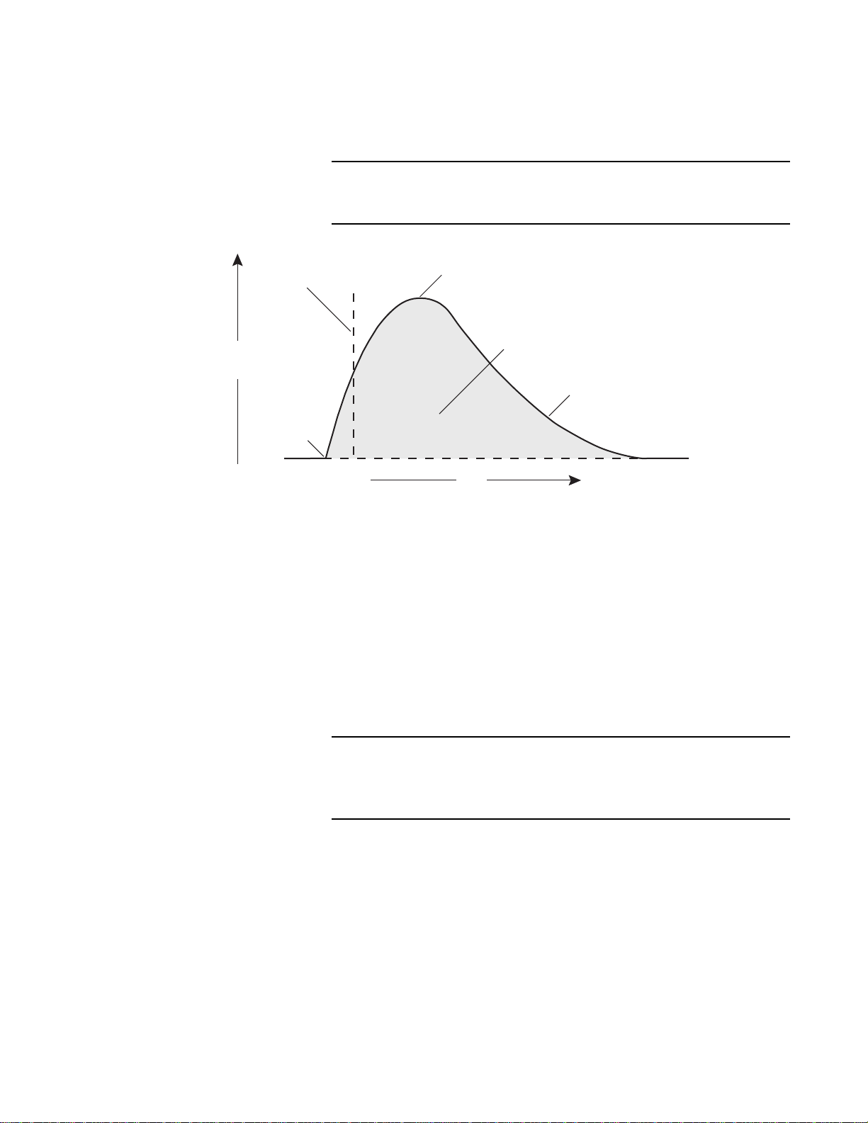
Operation
Peak Power
Algorithm integrates
this area
Pulse Start
Trigger
Joules Value
Ready
Time
Power
The power curve (shown below) is integrated from the pulse start to
infinity. The final energy value is algorithmically calculated shortly
after peak power is attained.
The trigger is not determined by the power threshold, but by the
slope of the change in power.
Figure 4-4. Pulsed Thermopile Joules Mode Power Curve
Collecting Pulsed Thermopile Joules Data Over a Host Port
Thermopile Sensors, Long Pulse Joules
To collect pulsed thermopile joules data:
1. Set the mode to Joules by using either the UNITS soft key on
the meter, or the CONFigure:MEASure host command.
2. Query the host for measurement data by using the
FETCh:NRECords query—for detailed information, refer to
“Data Query” (p. 6-51).
The type of data that will be collected depends entirely on which
mode is currently selected: Joules mode will collect only joules
data and Watts mode will collect only watts data.
Connecting a thermopile sensor to the meter and switching to Joules
mode displays the screen shown below. This mode measures the
energy of single pulses between 1 millisecond and 10 seconds in
4 - 7
Page 44
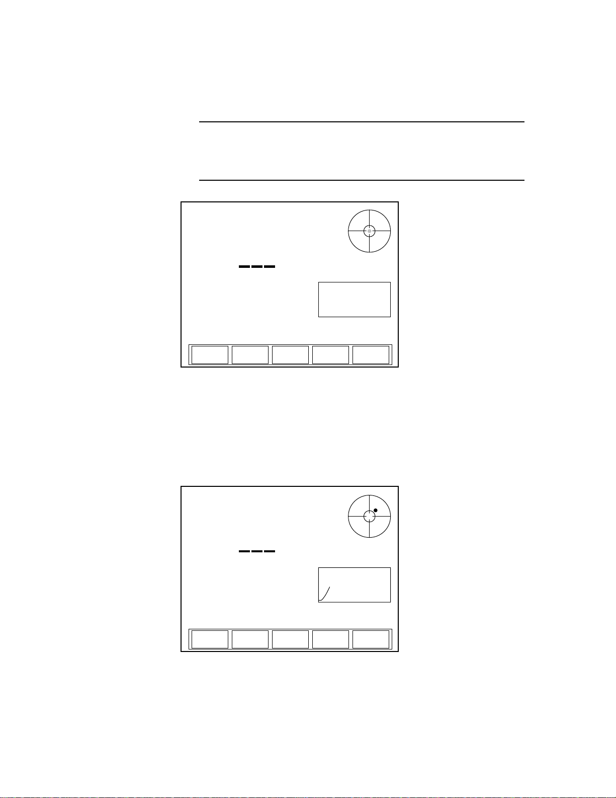
LabMax-TOP User Manual
MEASURE ENERGY
UNITS
Joules
STATS
Wavelength: Gain:
1.064 μm OFF
READY
5.2 mW
TRIGGER
Low
MEASURE ENERGY
UNITS
Joules
STATS
Wavelength: Gain:
1.064 μm OFF
CALCULATING
5.2 mW
TRIGGER
Low
length, and with energies from 5 mJ to hundreds of joules.
Measuring long mJ pulses requires more sensitive thermopiles (such
as a PS10Q).
When measuring energy with a thermopile sensor, the energy
range is sensor-dependent and is automatically determined by
the meter. The range value cannot be manually changed.
Figure 4-5. MEASURE ENERGY: Thermopile Sensors (Long Pulse Joules)
Display Smoothing and Speedup are not active in this mode. When
a pulse is received, the READY indicator in the upper left of the
screen changes to CALCULA TING, the position indicator shows the
beam position in the crosshairs of the bulls eye target (quad sensors
only), and a plot of the thermopile response begins, as shown below .
Figure 4-6. MEASURE ENERGY: Thermopile Sensors (Long Pulse - Active)
4 - 8
Page 45
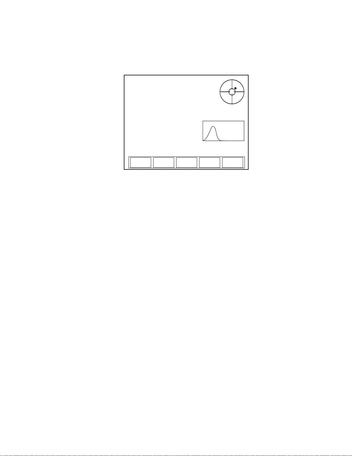
Operation
MEASURE ENERGY
UNITS
Joules
STATS
Wavelength: Gain:
1.064 μm OFF
READY
3.11 mJ
5.2 mW
TRIGGER
Low
Once the calculation has been completed, the new Joules value is
displayed, the CALCULATING indicator is replaced with READY,
and the plot stops (Figure 4-7). At this point, the meter is ready to
receive another pulse.
Figure 4-7. MEASURE ENERGY: Thermopile Sensors (Long Pulse - After Pulse)
Soft Keys
There are three soft keys on this screen: TRIGGER, UNITS, and
STATS.
TRIGGER
• Available values: Low (factory default), Medium, and High.
The purpose of the TRIGGER is to filter out ambient noise.
Low—the most sensitive of the three values—does the least
filtering. If that value produces an excessive number of false triggers
while taking a reading, select the Medium or High value to increase
the filtering.
Pressing the TRIGGER soft key cycles through the three values.
UNITS
Pressing the UNITS soft key toggles the measurement units back to
Watts and displays the MEASURE POWER screen.
STATS
Pressing the STATS soft key displays the ST ATS screen. For details
on the STATS screen, refer to information under “Statistics”
(p. 4-15).
4 - 9
Page 46
LabMax-TOP User Manual
MEASURE ENERGY
RANGE
300 μJ
UNITS
Joules
STATS
TRIG LEV
02%
TRIGGER
Wavelength: Gain: Smoothing:
1.064 μm OFF OFF
595 Hz
20 μJ
Pyroelectric Sensors Pressing the MEASURE button when a pyroelectric sensor is
attached to the meter will display a screen similar to the one shown
below.
The unit that appends to the live reading is determined by the
type of measurement selected with the UNITS soft key: Joules or
Watts.
Figure 4-8. MEASURE ENERGY: Pyroelectric Sensors
This screen contains the live reading and the rep rate. It also shows
the following indicators: Wavelength, Gain, and Smoothing. (A
summary of indicator behavior is provided in “Appendix C:
Onscreen Indicators” (p. C-1).)
Soft Keys
There are four soft keys on this screen: RANGE, UNITS, TRIG
LEV(el) (for internal trigger source) or TRIG DLY(delay) (for
external trigger source), and STATS.
RANGE
• Available values: Sensor-dependent.
To adjust the range:
1. Press the RANGE soft key.
2. Turn the Selection knob to change the range value.
3. When the desired value appears, press the RANGE soft key (or
the ENTER/SET button) to lock in the RANGE value.
4 - 10
Page 47

Operation
UNITS
Pressing the UNITS soft key toggles the measurement units between
Watts and Joules.
TRIG LEV(el) (for internal trigger source)
Available values: 2 (factory default) to 20%.
To adjust the level:
1. Press the TRIG LEV soft key.
2. Turn the Selection knob to change the value. The result of the
adjustment can be seen in the live measurement display . Adjust
the trigger threshold as low as possible to avoid noise triggers
while the laser is not firing.
3. When the desired value appears, either press the TRIG LEV
soft key or press the ENTER/SET button to lock in the value.
TRIG DLY(delay) (for external trigger source)
Available values: 0 (factory default) to 1000.
To adjust the level:
1. Press the TRIG DLY soft key.
2. Turn the Selection knob to change the value. When the desired
value appears, either press the TRIG DLY soft key or press the
ENTER/SET button to lock in the value.
Trigger Delay can also be adjusted on the Trigger screen in
SETUP. For more information, refer to “Trigger” (p. 4-58)
STATS
Refer to “Statistics” (p. 4-15) for information about the STATS
menu.
Pyroelectric Watts Mode
Using an attached pyroelectric sensor, LabMax-TOP can measure
average power from a series of pulses. By pressing the UNITS soft
key, the instrument toggles between displaying energy and
displaying average power.
Average power is calculated by measuring the energy of the pulses
and dividing by the periods between them and, thus, requires at least
two pulses to make a power measurement. Each subsequent pulse
4 - 11
Page 48
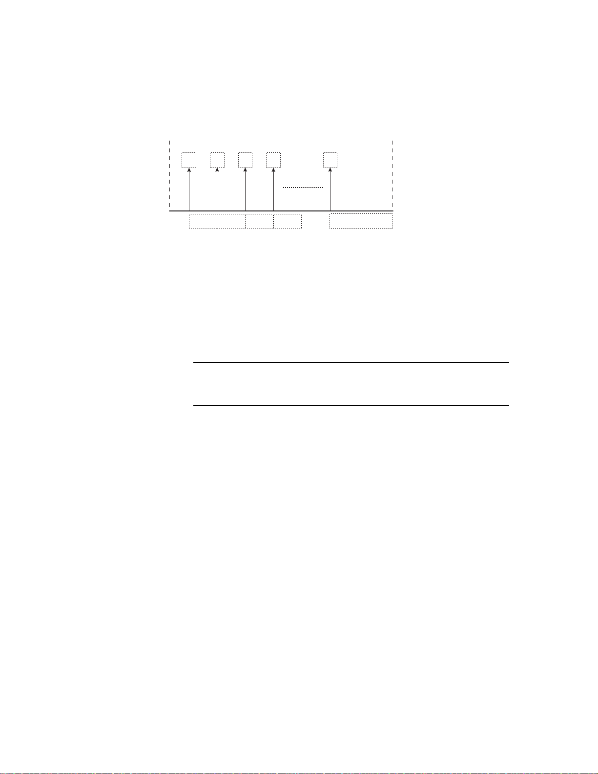
LabMax-TOP User Manual
indeterminate
E
0
E
1
E
2
E
3
E
n
t
t
t
t
t
defines the period for the previous pulse until the last pulse (see
Figure 4-9). The last pulse in a pulse burst will not yield a power
measurement since the period after the last pulse is indeterminate.
This method allows more accurate tracking of initial average power
transients for pulsed lasers.
0
1
2
3
n
Figure 4-9. Average Power Diagram
When measuring the average power of a laser burst or continuous
pulse train, the frequency of the pulses must be greater than or equal
to 1 Hz, and less than or equal to the maximum repetition rate capability of a compatible pyroelectric sensor. Multiple bursts separated
by one second or less are treated as a single burst and, accordingly,
the gap between bursts appears as a lower power.
Short bursts with rep rates greater than 1 kHz may not yield a
measurement.
Triggering LabMax must trigger reliably for each laser pulse.
LabMax may be triggered externally via the Ext Trig
connector—see “Ext Trig Connector” (p. 3-8). This is particularly
useful in a noisy environment. LabMax can be set to synchronize
with either the positive or negative transition of this external signal.
Without a reliable external trigger, set LabMax to use its own
internal circuitry to extract a trigger from the incoming signal. This
is called Internal Triggering (discussed, below). For more informa-
tion about setting the trigger source, refer to “Trigger” (p. 4-58).
Internal Triggering Mode
Internal triggering refers to finding a trigger automatically from the
incoming signal.
To successfully extract an internally-generated trigger, set the meter
range so that the incoming signal is at least 5% of the full scale. Set
the trigger level at least 2% above the noise level and at least 2%
below the percent of full scale that you plan to measure.
4 - 12
Page 49
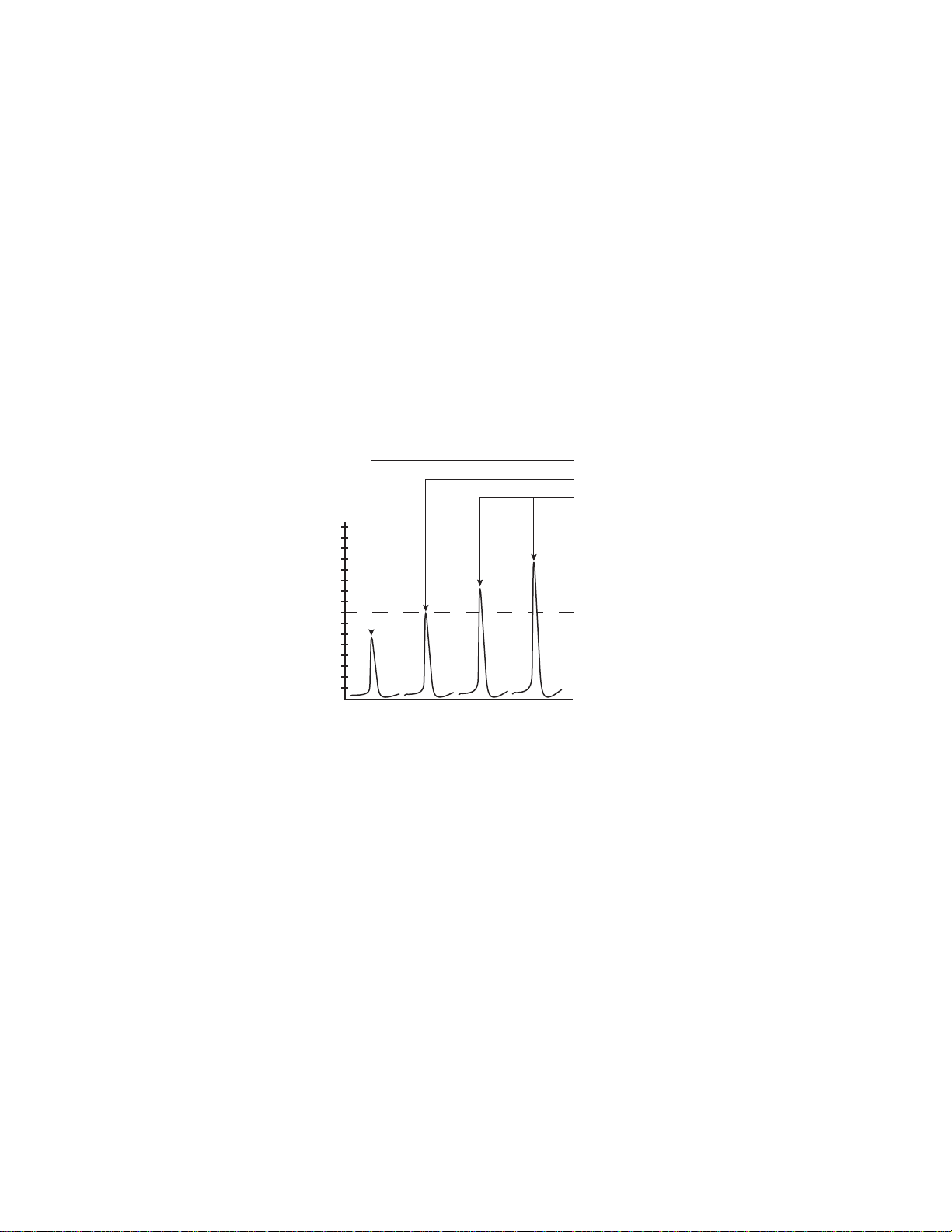
Operation
8% Trigger Level
15%
10%
5%
Definitely will trigger
May trigger, but not reliable
Definitely will not trigger
A
B C D
For example if you plan to measure pulses that are approximately
300 mJ, set the meter to a range of 3J. A peak will occur at 10% of
full scale, well above the 5% level. The trigger level should not be
set higher than 8%. If the noise level is 5% of full scale (approximately 150 mJ), the trigger level should not be set lower than 7%.
To find the level at which noise triggers, make sure the laser shutter
is closed and start turning down the trigger threshold level. At some
point you may notice that the meter picks up trigger events and
displays energy measurements. This is considered the noise level.
Depending upon the sensor model and the range selected, you may
or may not detect noise triggers above 2% of full scale range.
In Figure 4-10, the internal trigger threshold has been set to 8%
(shown as a dashed line). Pulse A will definitely not generate a reliable trigger. Pulse B may generate a trigger, but not reliably. Pulses
C and D will definitely generate reliable triggers.
Figure 4-10. Internal Trigger Threshold
A full-scale signal on one range may not trigger on the next higher
range unless the trigger level is set to less than 10%. For example, a
near full-scale signal of 280 mJ on the 300 mJ range is less than 10%
of full scale on the next higher range (3J), and would therefore not
trigger the reading. To obtain reliable triggering in this instance,
adjust the trigger level to less than 8%.
The trigger is synchronous with the leading edge of the pulse, but the
actual peak is determined algorithmically by sampling the input
signal near the trigger. From the trigger point forward, the algorithm
searches for peaks and from the trigger point back, it searches for a
baseline.
4 - 13
Page 50

LabMax-TOP User Manual
Trigger States and the Trigger Annunciator
The trigger state is always displayed when a pyroelectric sensor
is attached and the trigger source is set to Internal.
Two annunciators indicate the trigger state of the meter: TRIGGER
and the ? segment that follows it.
There are two possible trigger states when a pyroelectric sensor is
attached: triggered and wait for trigger . The triggered state indicates
that the meter is capturing laser pulses (or is triggering on noise).
The wait for trigger state indicates an absence of pulse triggers.
When a pulse is captured, the trigger state becomes active and the
wait for trigger state becomes inactive. If no pulses are captured
within 2 seconds since the last pulse was captured, the wait for
trigger state becomes active and the triggered state becomes inactive. The TRIGGER annunciator reads “TRIGGER” in the triggered
state and “TRIGGER?” in the wait for trigger state.
Pulse Sampling Pulse sampling refers to how many pulses are read within a series of
pulses. For example, when receiving 2,500 pulses per second, pulse
sampling reads (that is, samples) every third incoming pulse.
Table 4-2 shows how many pulses are sampled, depending on the
number of incoming pulses per second.
Table 4-2. Approximate Pulse Sampling Based on the Number of Incoming Pulses
Incoming Pulses Pulses Read
<1,000 Every pulse is read (pulse sampling is not active)
1,000 to 2,000 Every second pulse is read
2,001 to 3,000 Every third pulse is read
3,001 to 4,000 Every fourth pulse is read
4,001 to 5,000 Every fifth pulse is read
5,001 to 6,000 Every sixth pulse is read
6,001 to 7,000 Every seventh pulse is read
7,001 to 8,000 Every eighth pulse is read
8,001 to 9,000 Every ninth pulse is read
9,001 to 10,000 Every tenth pulse is read
>10,000
Pulse sampling continues to approximately 15 kHz but
is not guaranteed to meet instrument specifications
4 - 14
Page 51

Statistics
S
xix–()
2
i 1=
N
N 1–
-----------------------------=
Statistics Calculations Standard Deviation
In this formula, x is the value of the mean, N is the sample size, and
xi represents each data value from i=1 to i=N.. The Ʃ symbol indi-
cates that you must add up the sum (x1 - x)2 + (x2 - x)2 + (x3 - x)2 +
(x4 - x)2 + (x5 - x)2. . . + (xN - x)2.
Range
The difference between the maximum and minimum values in a
batch of samples.
σ
Operation
The ratio of the standard deviation divided by the batch mean value
in percent. (often used for stability measurements)
2σ
Two times the sigma calculation. (often used for stability measure-
ments)
3σ
Three times the sigma calculation. (often used for stability measure-
ments)
Dose
The cumulative sum of all energy pulses collected within a batch
when using a pyroelectric sensor in Joules mode.
Missed Pulses
The number of pulses missed during a batch when the meter is exter-
nally triggered. When the LabMax is used in energy mode with an
external trigger, the meter counts how many trigger signals are sent
to the meter versus how many actual energy measurements were
received. Any trigger signals that do not capture a valid energy
measurement are considered missed pulses and are recorded by this
statistic.
4 - 15
Page 52
LabMax-TOP User Manual
STATS
RANGE
Auto
RESTART
Manual
STATS
STATS
SETUP
Wavelength:
514 nm
Gain:
OFF
Smoothing:
OFF
Duration: 00:10 Elapsed: 00:00
Min: --- Max: ---
Mean: --- Std Dev: ---
START
CHANGE
Live: 22.1W
STATS
RANGE
300 μJ
RESTART
Manual
STATS
STATS
SETUP
Wavelength:
1,064 μm
Gain:
OFF
Smoothing:
OFF
Duration: 10
Live: 15 μJ 581 Hz
Elapsed: 0
Min: --- Max: ---
Mean: --- Std Dev: ---
START
CHANGE
TRIGGER
Figure 4-11. STATS: Thermopile and Optical Sensors
Pressing the STATS soft key from the MEASURE screen will
display the screen in Figure 4-11 (for thermopile or optical sensors),
or Figure 4-12 (for pyroelectric sensors).
Figure 4-12. STATS: Pyroelectric Sensors
The STATS screen displays the live measurement and, by default,
the Min, Mean, Max, and Standard Deviation values. It is possible
to modify the parameters shown on this screen by selecting up to six
statistics for display. To learn how to select different statistics, refer
to “CHANGE STATS” (p. 4-19).
The Duration indicator in the upper left corner of the STATS screen
can be changed in Stats Setup—discussed under “STATS SETUP
Description” (p. 4-19). See “Appendix C: Onscreen Indicators”
(p. C-1) for a summary of indicators and their behavior.
Soft Keys
There are five soft keys on this screen: ST AR T , RANGE, RESTART ,
STATS SETUP, and CHANGE STATS.
4 - 16
Page 53
START
STATS
RANGE
Auto
RESTART
Manual
STATS
STATS
SETUP
Wavelength:
514 nm Gain: OFF Smoothing: OFF
Duration: 00:10
Live: 22.2 W
Elapsed: 00:03
Mean: 22.2 W Std Dev: 3.90 mW
STOP
CHANGE
Min: 22.2 W Max: 22.3 W
Pressing the START soft key begins data collection. The statistics
appear on the screen as the batch is collected (see the following
example):
Figure 4-13. STATS: Data Collection (In Process)
Operation
Pressing the STOP key—which appears in place of the START
key during data collection—ends data collection.
RANGE
• Available values (thermopile and optical sensors): Auto
(factory default) and the allowable ranges for the attached
sensor.
• Available values (pyroelectric sensors): Sensor-dependent.
To adjust the range:
1. Press the RANGE soft key.
2. Turn the Selection knob to change the range value.
3. When the desired value appears, press the RANGE soft key (or
the ENTER/SET button) to lock in the RANGE value.
4 - 17
Page 54
LabMax-TOP User Manual
STATS
RANGE
Auto
RESTART
Manual
STATS
STATS
SETUP
Wavelength:
514 nm Gain: OFF Smoothing: ON
Duration: 00:10
Live: 22.2 W
Elapsed: 00:10
Mean: 22.2 W Std Dev: 6.74 mW
START
CHANGE
Min: 22.2 W Max: 22.2 W
RESTART
The RESTART soft key on the STATS screen toggles between
Manual (factory default) mode and Auto mode.
Figure 4-14. STATS: Statistics Readout
Manual Mode
In Manual mode, pressing the START soft key begins data collection. Data collection ends by:
• Pressing the STOP soft key—which appears in place of the
START key during data collection.
• Reaching the time duration that was set for data collec-
tion—see “ST ATS SETUP Description” (p. 4-19) for information about setting the time duration.
Auto Mode
Auto mode acts similar to Manual mode, except that once data
collection reaches the time duration, the batch automatically starts
over.
As with Manual RESTART, pressing the STOP soft key immediately stops data collection.
STATS SETUP
Refer to “STATS SETUP Description” (p. 4-19).
4 - 18
Page 55
Operation
EXIT
STATS: Change Stats
Min
Max
Mean
Standard deviation
Range
ıPHDQLQ
ıPHDQLQVWDELOLW\
ıPHDQLQ
6HOHFWXSWR
SDUDPHWHUV
WRGLVSOD\
Dose
0LVVHG3XOVHV
CHANGE STATS
Pressing the CHANGE STATS soft key on the STATS screen
displays the following screen:
Figure 4-15. STATS: Change Stats
The Dose parameter appears only when using a pyroelectric
sensor in energy mode. The Missed Pulses parameter is available
only when in external trigger mode with a pyroelectric sensor.
Up to six items can be selected for display on the STATS screen.
To select an item:
1. Turn the Selection knob to move the highlight up or down the
list.
2. Press the ENTER/SET button to select or de-select an item.
3. Press the EXIT soft key to save the settings and exit Change
Stats mode.
STATS SETUP Description
Statistics batch size is specified on this screen. The total amount of
time and the rate at which data is collected can be adjusted. Note that
with pyroelectric energy sensors, the batch size is specified in terms
of pulses, not time.
By default, thermopile and optical sensors are sampled 10 times per
second. This is the maximum sampling rate possible. Pyroelectric
energy sensors have a factory default sample rate of one sample per
laser pulse. Using the STATS Setup screen lets you set the meter so
that it does not sample every single laser pulse.
4 - 19
Page 56
LabMax-TOP User Manual
<<-
STATS: Setup
Display units:
CANCEL
Watts
Duration:
Sampling rate: 10
Batch Size:
SAVE ->>
100
00:00:00:10 (days:hr:min:sec)
00:00:01
samples every
(hr:min:sec)
STATS: Setup
Display units:
CANCEL
Watts
Duration:
Sampling rate: 1
Batch Size:
SAVE ->> <<-
10
0000000010 pulses
00001
sample every
pulse(s)
T o change the current stat settings, press the ST ATS SETUP soft key .
Depending on the type of sensor attached to the meter and the
measurement being taken, one of the following STATS: Setup
screens will appear:
• Thermopile or optical sensor (Figure 4-16)
• Pyroelectric sensor measuring power (Figure 4-17)
• Pyroelectric sensor measuring energy (Figure 4-18)
Figure 4-16. STATS: Setup (Thermopile and Optical Sensors)
Figure 4-17. STATS: Setup (Pyroelectric Sensors - Power)
4 - 20
Page 57
Figure 4-18. STATS: Setup (Pyroelectric Sensors - Energy)
STATS: Setup
Display units:
CANCEL
Joules
Duration:
Sampling rate: 1
Batch Size:
SAVE ->> <<-
10
0000000010 pulses
00001
samples every
pulse(s)
Soft Keys
There are four soft keys on this screen: <<-/->> (Previous/Next
directional arrows), SAVE, and CANCEL.
Operation
<<- and ->> (directional arrows)
Parameters on this screen are changed by using one of the following
procedures. The procedure that should be used depends on the type
of parameter you want to modify.
“Single” Parameters
This type of parameter—Display units, for example—has only one
modifiable field. To change a value for this type of parameter:
1. Press the ENTER/SET button until the parameter you want to
change is highlighted.
2. Turn the Selection knob to change the parameter value.
3. Press the ENTER/SET button to move to the next parameter.
4. Continue this process until the values for all the parameters are
correct.
5. Once the values for all the parameters are correct, press the
SAVE soft key to save the parameters and display the STATS
screen.
4 - 21
Page 58

LabMax-TOP User Manual
“Multiple” Parameters
This type of parameter—Duration, for example—contains several
fields that can be modified. T o change a value for this type of parameter:
1. Press the ENTER/SET button until the parameter you want to
change is highlighted.
2. Turn the Selection knob to change the parameter value.
3. Press either of the directional arrows soft keys (<<- or ->>) to
move the highlight to another value within the same parameter .
4. Repeat steps 2 and 3 until all values for that parameter are
correct.
5. Press the ENTER/SET button to move to the next parameter.
6. Once the values for all the parameters are correct, press the
SAVE soft key to save the parameters and dis play the STATS
screen.
SAVE
Pressing the SAVE soft key saves whatever changes were made
since the last SAVE and displays the STATS screen.
CANCEL
Pressing the CANCEL soft key discards all changes that were made
since the last SAVE and displays the STATS screen.
4 - 22
Page 59
Operation
POSITION STABILITY
CHANGE
DURATION
X: 0.2 mm Y: -0.5 mm
-9.5
01:00
9.5
Duration: 01:00 Elapsed: 00:00
VIEW
Scroll
START EXIT
Detailed Procedures
This section provides in-depth information about specific topics that
were briefly discussed earlier.
POSITION STABILITY When a quad thermopile sensor is attached to the meter, pressing the
POSITION STABILITY soft key on the MEASURE POWER
screen will display a screen similar to the following:
Figure 4-19. MEASURE POWER: POSITION STABILITY
The X-axis of the graph is time and the Y-axis is based on the diameter of the sensor active area.
The Duration indicator in the upper left shows how long the meter
will collect data.The Elapsed indicator in the upper right corner
begins its count when the START soft key is pressed.
The actual X and Y values (just above the graph) update as the data
is collected.
Soft Keys
There are four soft keys on this screen: START, VIEW, CHANGE
DURATION, and EXIT.
START
Pressing the START soft key starts data collection and toggles the
soft key to STOP. When data collection completes (either by
pressing the STOP button or as determined by the previously-set
duration), the button toggles to START again. Pressing START
when there is already data on screen, clears that data and starts data
collection over.
4 - 23
Page 60
LabMax-TOP User Manual
Duration: 00:00:01 Elapsed: 00:00
POSITION STABILITY
CHANGE
DURATION
X: 0.2 mm Y: -0.5 mm
-9.5
00:01
9.5
EXIT
->> <<-
VIEW
The VIEW soft key toggles between Scroll and Fit:
• Fit—Fits the entire duration on the X-axis in one screen
• Scroll—Pages the data every minute
CHANGE DURATION
Pressing the CHANGE DURATION soft key accesses the Duration
field in the upper left corner of the screen, as shown here:
Figure 4-20. POSITION STABILITY: Duration
To change the duration:
1. Use the left and right arrow soft keys to highlight an individual
2. Turn the Selection knob to change the value of the
3. Repeat steps 1 and 2 until the desired duration has been
4. To save the duration, either press the ENTER/SET button
EXIT
Pressing the EXIT soft key displays the MEASURE POWER
screen.
duration field (hours, minutes, or seconds).
currently-highlighted field.
entered.
(which will display the POSITION STABILITY screen), or
press the EXIT soft key (which will exit POSITION
STABILITY mode and display the MEASURE POWER
screen).
4 - 24
Page 61
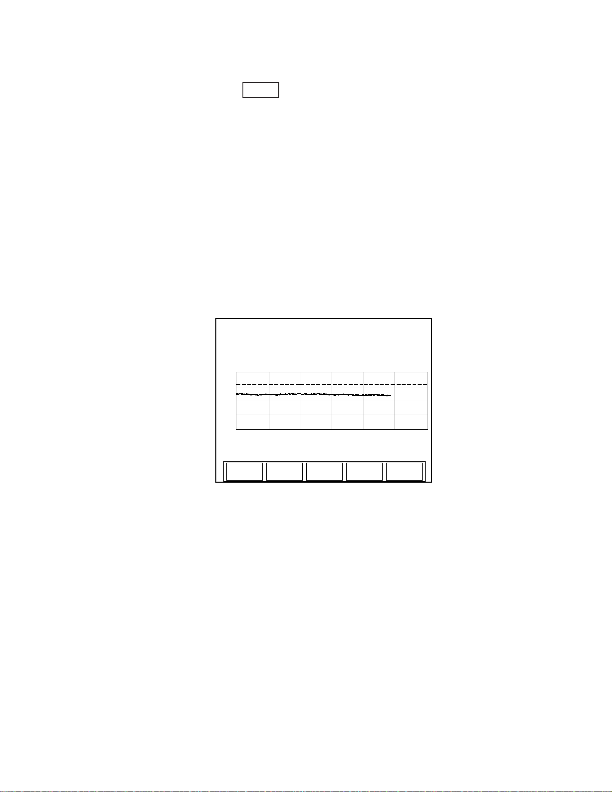
Operation
TUNE
TUNE
RANGE
Auto
VERT
1X
RESET
Wavelength:
nm
Gain: Smoothing:
532 OFF OFF
Live: 22.3 W Max: 22.4 W
VIEW Strip
0
60 sec
Chart
HORIZ
1X
25
TUNE
Strip Chart
Pressing the TUNE button on the front panel of the meter
will enter the TUNE mode. This mode is used in place of
an analog needle to monitor the laser output while tuning
or tweaking the laser. Typically the laser output is being
maximized during the process, and both tuning screens—Strip chart
and Bar chart—contain peak indicators and display the maximum
measured value since the laser Reset event. Details of the strip chart
and bar chart are discussed next.
Figure 4-21 shows an example Strip chart screen for both thermopile
and optical sensors. Press the RESET soft key to reset the peak indicator, maximum measured value, and vertical scale. When the
Vertical scale factor is set to 1X, pressing the RESET soft key will
also clear the display . When in a higher scale factor , the screen is not
cleared but the factors are reset and the plot is centered on the live
reading.
Figure 4-21. TUNE: Strip Chart (Thermopile and Optical Sensors)
Soft Keys
There are five soft keys on this screen: VIEW, RANGE, VERT,
HORIZ, and RESET.
VIEW
Pressing the VIEW soft key at the bottom of the TUNE screen
toggles between the Strip chart and the Bar chart—for more information about Bar charts, refer to “Bar Chart” (p. 4-26).
RANGE
• Available values (thermopile and optical sensors): Auto
(factory default) and the allowable ranges for the attached
sensor.
4 - 25
Page 62

LabMax-TOP User Manual
• Available values (pyroelectric sensors): Sensor-dependent.
To adjust the range:
1. Press the RANGE soft key.
2. Turn the Selection knob to change the range value.
3. When the desired value appears, press the RANGE soft key (or
the ENTER/SET button) to lock in the RANGE value.
VERT
Pressing the VERT soft key zooms in and out on the Y-axis
presented in the TUNE chart. Zooming does not disturb data collection. Available zoom levels are 1, 2, 5, 10, and 20X.
To change the VERT level:
1. Press the VERT soft key.
2. Turn the Selection knob to change the VERT value.
3. When the desired value appears, press the VERT soft key (or
the ENTER/SET button) to lock in the VERT value.
HORIZ
Pressing the HORIZ soft key zooms in and out on the X-axis
presented in the TUNE chart. Zooming does not disturb data collection. Available zoom levels are 1, 2, 5, 10, and 20X.
To change the HORIZ level:
1. Press the HORIZ soft key.
2. Turn the Selection knob to change the HORIZ value.
3. When the desired value appears, press the HORIZ soft key (or
the ENTER/SET button) to lock in the HORIZ value.
RESET
Pressing this soft key resets the Max value.
Bar Chart
Figure 4-22 (p. 4-27) shows an example Bar chart screen for thermopile and optical sensors. Press the RESET soft key to reset the
peak indicator, maximum measured value, and vertical scale. When
4 - 26
Page 63
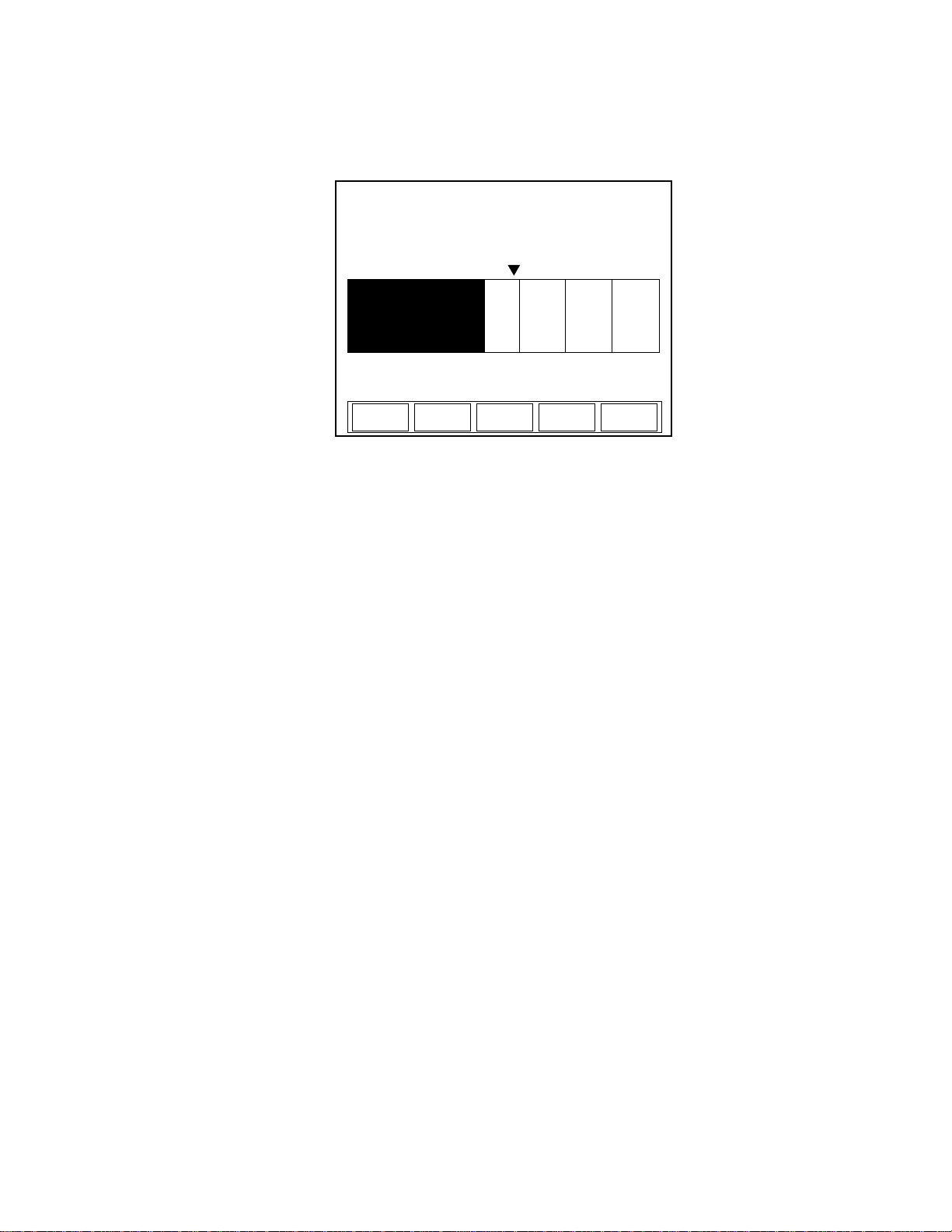
the Zoom scale factor is set to anything greater than 1X, pressing the
TUNE
RANGE
Auto
ZOOM
1X
RESET
Wavelength:
514 nm Gain: OFF Smoothing: OFF
Live: 22.2 W Max: 27.7 W
VIEW Bar
0 50
Chart
RESET soft key will also reset the x-axis scale factors to center the
indicator bar on the live value.
Figure 4-22. TUNE: Bar Chart (Thermopile and Optical Sensors)
Soft Keys
Operation
There are four soft keys on this screen: VIEW , RANGE, ZOOM, and
RESET.
VIEW
Pressing the VIEW soft key at the bottom of the TUNE screen
toggles between the Bar chart and the Strip chart—for more information about Strip charts, refer to “Strip Chart” (p. 4-25).
RANGE
• Available values (thermopile and optical sensors): Auto
(factory default) and the allowable ranges for the attached
sensor.
• Available values (pyroelectric sensors): Sensor-dependent.
To adjust the range:
1. Press the RANGE soft key.
2. Turn the Selection knob to change the range value.
3. When the desired value appears, press the RANGE soft key (or
the ENTER/SET button) to lock in the RANGE value.
ZOOM
Pressing the ZOOM soft key zooms in and out on the Y-axis
presented in the TUNE chart. Zooming in on the displayed data is
useful if you are trying to resolve small changes in laser output that
4 - 27
Page 64

LabMax-TOP User Manual
TREND
TREND
CREATE
FILE
FILE
MANAGER
VIEW
Live: 22.2 W
Min: ---
0.00
00:10
TREND
SETUP
3.00
Duration: 00:10 Elapsed: 00:00
Scroll
START
Std Dev:
---
Mean: ---
Max: ---
cannot be easily seen in the full scale, non-zoomed state. Zooming
does not disturb data collection. Available zoom levels are 1, 2, 5,
10, and 20X.
To change the ZOOM level:
1. Press the ZOOM soft key.
2. Turn the Selection knob to change the ZOOM value.
3. When the desired value appears, press the ZOOM soft key (or
the ENTER/SET button) to lock in the ZOOM value.
RESET
Pressing this soft key resets the Max value.
TREND
Trend is the mode in which data can be logged to a file
onboard the meter or to a USB flash drive. Additionally,
the trend history of the data is displayed as it is logged.
Versatile data logging in trend mode is supported by a
File Management function that provides file naming (including
auto-sequencing of file names), folder creation, as well as saving,
moving, and deleting files and folders.
Depending upon the sensor and display units in use, pressing the
TREND button on the front panel displays one of the following
screens:
Figure 4-23. TREND: Thermopile and Optical Sensors
4 - 28
Page 65
Operation
CREATE
FILE
FILE
MANAGER
VIEW
0.00
START
TREND
SETUP
3.00
Scroll
TREND
Live:
17 μJ
Min: ---
Duration: 10 Elapsed: 0
Std Dev: ---
Mean: ---
Max: ---
TRIGGER?
Figure 4-24. TREND: Pyroelectric Sensors
The indicator in the upper left corner—Duration—displays the
factory default batch size setting. If this setting is acceptable, press
the ST AR T soft key to begin data collection. T o change the duration:
• Press the TREND SETUP soft key on the TREND screen to
display the TREND: Setup menu.
• Use the left arrow and right arrow soft keys to advance through
the individual duration fields (days, hours, minutes, or
seconds).
• When a specific field is highlighted, turn the Selection knob to
change the value of that field.
• Press the SAVE soft key to save the new duration and display
the TREND screen.
• Press the START soft key to begin data collection.
To save the data locally, do one of the following:
• Use the CREATE FILE soft key to create and name a file
before starting data collection—refer to “Name Log File”
(p. 4-34).
• Use the SAVE DATA soft key—which appears in place of the
CREATE FILE soft key once data collection is complete—to
save a file after data collection. This is useful if you decide you
want to keep the data after collecting it and viewing it on the
trend chart. For more information, refer to “TREND Screen
After Data Collection” (p. 4-32).
Soft Keys
There are five soft keys on the main TREND screen: START,
CREATE FILE, FILE MANAGER, TREND SETUP, and VIEW.
4 - 29
Page 66

LabMax-TOP User Manual
RESET
ZOOM
1X
VIEW
0
00:10
25
Scroll
STOP
TREND
Live:
22.2 W
Min: 10.4 W
Duration: 00:10 Elapsed: 00:07
Std Dev: 2.63 mW
Mean: 14.3 W
Max: 21.5 W
START
Pressing the STAR T soft key on the main TREND screen starts data
collection.
CREATE FILE
Refer to “Name Log File” (p. 4-34).
FILE MANAGER
The FILE MANAGER screen is discussed in detail under “File
Manager” (p. 4-36).
TREND SETUP
The TREND SETUP screen is discussed in detail under “TREND
Setup” (p. 4-41).
VIEW
TREND Screen During Data Collection
The VIEW soft key on the main TREND screen toggles between
Scroll and Fit:
• Fit—Fits the entire duration on the X-axis in one screen
• Scroll—Pages the data every minute
Figure 4-25 shows an example of how the TREND screen looks
during data collection:
Figure 4-25. TREND: During Data Collection
4 - 30
Page 67

Operation
Soft Keys
There are four soft key on this screen: STOP, RESET, ZOOM, and
VIEW
STOP
Pressing the STOP soft key immediately stops batch collection and
displays the soft keys described under the heading “TREND Screen
After Data Collection” (p. 4-32).
RESET
Pressing the RESET soft key stops batch collection, clears the
screen, and displays the soft keys described under the heading
“TREND” (p. 4-28).
ZOOM
The ZOOM soft key zooms in or out on the Y-axis presented in the
TREND chart. Zooming does not disturb data collection.
To change the zoom:
1. Press the ZOOM soft key.
2. Turn the Selection knob to select a new zoom level.
3. When the desired value appears, press the ZOOM soft key (or
the ENTER/SET button) to lock in the ZOOM value.
VIEW
The VIEW soft key toggles between Fit and Scroll. It is possible to
toggle back and forth between Fit and Scroll during data collection.
• Fit—Fits the entire duration on the X-axis in one screen. The
collected data is decimated to allow it to be viewable on a
single screen.
• Scroll—Pages the data. After the trend is completed, the data
on previous pages can be viewed. If viewing in Scroll mode,
turn the Selection knob to scroll back through the data. In this
viewing mode, every logged data point is visible.
4 - 31
Page 68
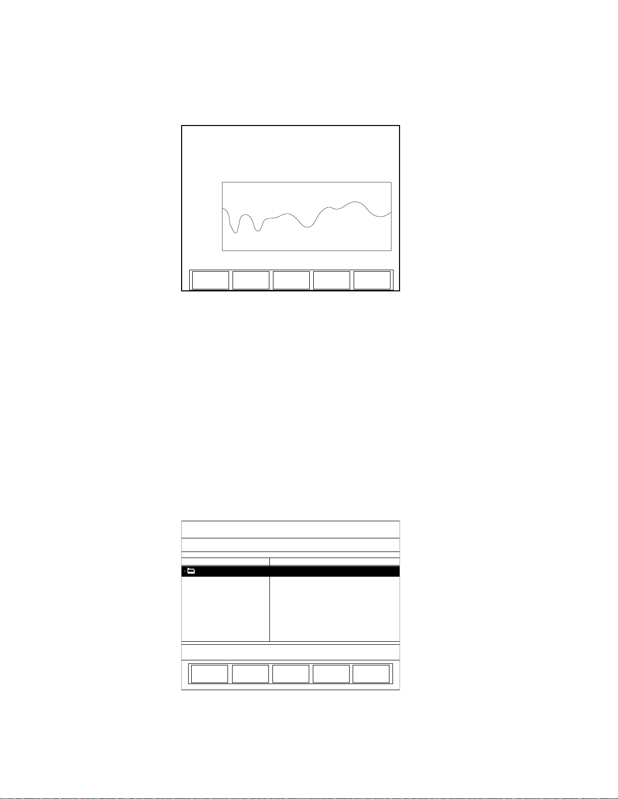
LabMax-TOP User Manual
0
00:10
25
SAVE
DATA
ZOOM
1X
VIEW
Scroll
RESET
TREND
Live:
22.2 W
Min: 10.4 W
Duration: 00:10 Elapsed: 00:07
Std Dev: 2.63 mW
Mean: 14.3 W
Max: 21.5 W
CANCEL
TREND: File Manager
SAVE
AS
/loc
CREATE
FOLDER
. . 190
Name Size (bytes)
Tmp Data Save
TREND Screen After Data Collection
Figure 4-25 shows and example of what the TREND screen looks
like after data collection:
Figure 4-26. TREND: After Data Collection
Soft Keys
There are four soft keys on this screen: RESET, SAVE DATA,
ZOOM, and VIEW.
RESET
Pressing the RESET soft key stops batch collection, clears the
screen, and displays the soft keys described under the heading
“TREND” (p. 4-28).
SAVE DATA
Pressing this soft key displays the following screen:
Figure 4-27. TREND: File Manager (Save Data)
4 - 32
Page 69
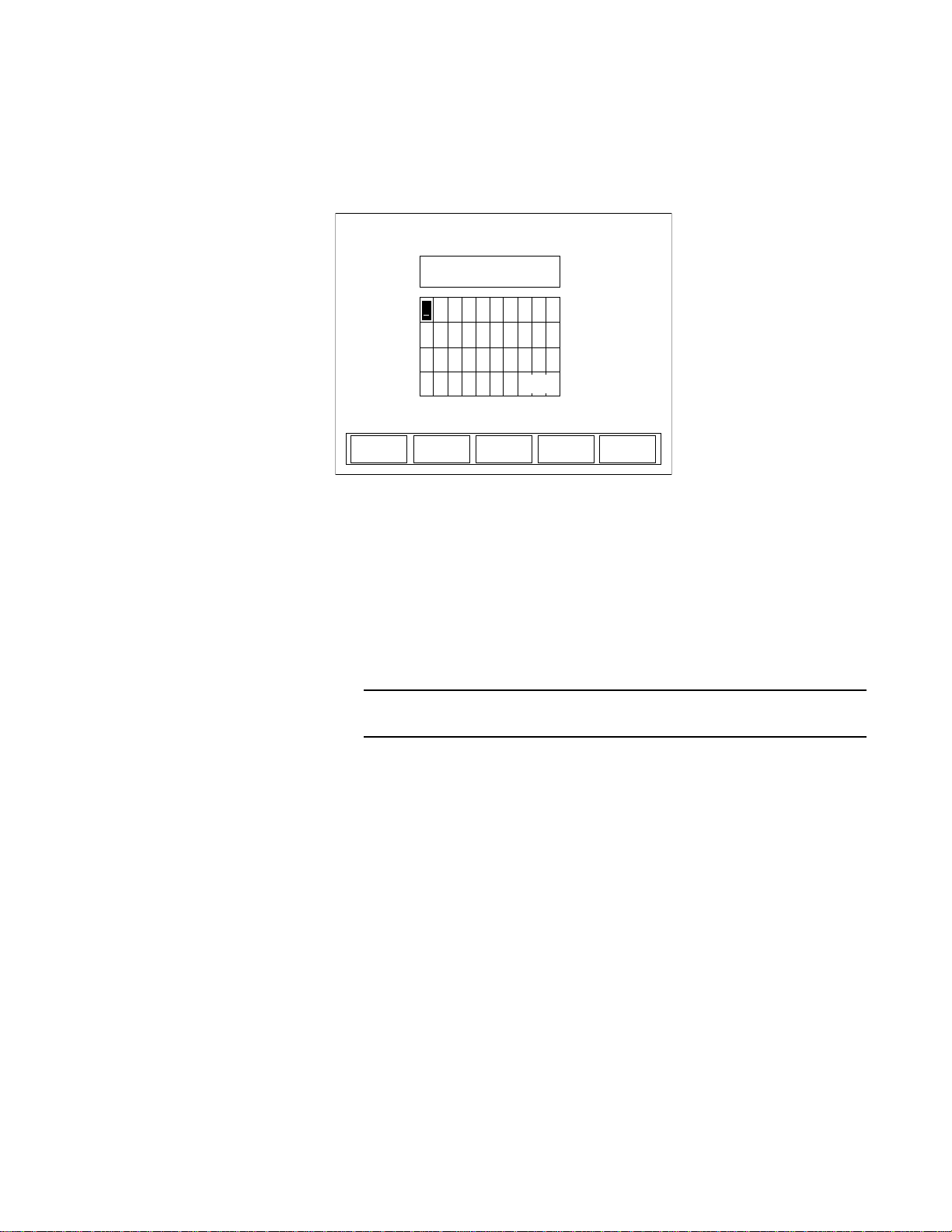
Operation
TREND: Save Tmp As
CANCEL
BACK
SPACE
SAVE
Rotate Knob
to choose letter.
Press to select.
b c j i h g f e d
k l m t s r q p o n
u v w 3 2 1 0 z y x
4
5 6 space - 9 8 7
a
space
There are three soft keys on this screen: SAVE AS, CREATE
FOLDER, and CANCEL.
Pressing the SAVE AS soft key will display the TREND: Save Tmp
As screen:
Figure 4-28. TREND: Save Tmp As
To create a file:
1. Select the first character of the file name by turning the Selection knob and then pressing the ENTER/SET button when the
desired letter or number is highlighted. The character will
appear in the blank box immediately below the screen heading.
To delete a character, use the BACKSPACE soft key.
2. Repeat step 1 until the entire new file name appears in the box.
3. Press the SAVE soft key, which will display a file management
dialog screen confirming the file is being copied.
4. Once copying is complete (as indicated by the bar on the
dialog screen displaying the text, 100%), press the
ENTER/SET button to dismiss the dialog box.
Pressing the CREATE FOLDER soft key on the TREND: File
Manager screen displays the TREND: Create New Folder
screen—refer to “CREATE FOLDER” (p. 4-40).
Pressing the CANCEL soft key displays the main TREND screen.
ZOOM
The ZOOM soft key zooms in or out on the Y-axis presented in the
TREND chart. Zooming does not disturb data collection.
4 - 33
Page 70
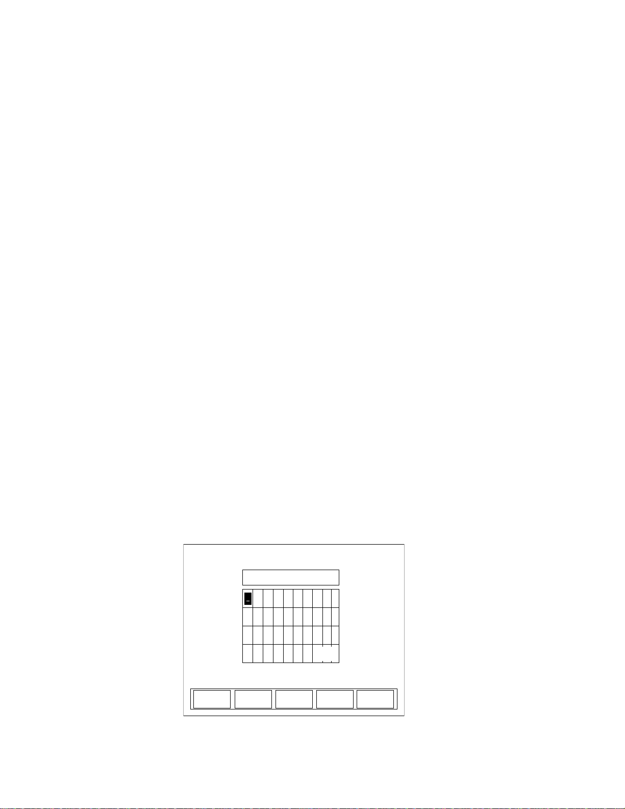
LabMax-TOP User Manual
CANCEL
TREND: Name Log File
SAVE
Pattern
BACK
Sequence
None
SPACE
a b c d e f g h i j
k l m n o p q r s t
u v w x y z 0 1 2 3
4 5 6 7 8 9 - space
/loc/.csv
Rotate Knob
to choose letter.
Press to select.
space
To change the zoom:
1. Press the ZOOM soft key.
2. Turn the Selection knob to select a new zoom level.
3. When the desired value appears, press the ZOOM soft key (or
the ENTER/SET button) to lock in the ZOOM value.
VIEW
The VIEW soft key toggles between Fit and Scroll.
• Fit—Fits the entire duration on the X-axis in one screen
• Scroll—Pages the data every minute
Detailed Procedures
This section provides in-depth information about specific topics that
were briefly discussed earlier.
Name Log File Use this screen to create a file before starting data collection. The log
file is saved to the location previously navigated in File Manager.
For example, if you use File Manager to navigate to a USB flash
drive that is attached to the meter, and then subsequently create a
named log file, the file will be saved to the folder in the USB flash
drive you had previously navigated to. If you did not previously
navigated to a specific location in File Manager, the file is saved to
the local drive in the meter.
To create a file:
1. Press the CREATE FILE soft key on the TREND screen to
display the TREND: Name Log File screen (Figure 4-29):
Figure 4-29. TREND: Name Log File
4 - 34
Page 71

Operation
2. Select the first character of the file name by turning the Selection knob and then pressing the ENTER/SET button when the
desired letter or number is highlighted. The character will
appear in the blank box immediately below the screen heading.
To delete a character, use the BACKSPACE soft key.
3. Repeat step 2 until the entire file name appears in the box.
4. Press the SAVE soft key to save the new file name and display
the TREND screen.
The new file name will appear on the bottom left of the TREND
screen (just above the START soft key).
Soft Keys
There are five soft keys on this screen: BACKSPACE, Pattern,
Sequence, SAVE, and CANCEL.
BACKSPACE
This soft key backspaces one editable field and deletes the character
that was there.
Pattern
Pressing this soft key appends the current date to the file name. This
feature is a useful way to manage logged data. The date is appended
to any name you entered in the Name File dialog box. For example,
if today is February 2, 2008, and you name a file /loc/test.csv,
pressing the Pattern soft key will change the file name to
/loc/test02-04-08.csv. Note that pressing this soft key also changes
the soft key name from Pattern to Pattern Date.
Sequence
The Sequence soft key toggles between Auto and None (factory
default).
• Auto—Appends a sequentially-incrementing identification
number to the file name. As files are created by pressing the
ST ART and STOP soft keys (on the TREND screen), the identification number in the file name automatically increments.
This is useful if you are creating several similar log files and
want to prevent accidental overwriting of one of the data files.
It is also useful in identifying the order in which data files were
4 - 35
Page 72
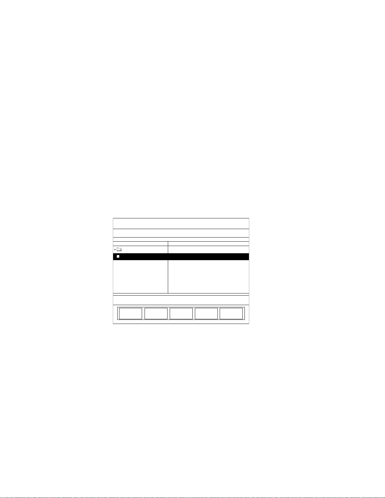
LabMax-TOP User Manual
EXIT
TREND: File Manager
DELETE
COPY
MOVE
/loc
CREATE
FOLDER
. . 10
Name Size (bytes)
test.csv 6300
RENAME
created. The Pattern and Sequence functions can be used
together.
• None—Does not append an identification number to the file
name
SAVE
Pressing the SAVE soft key saves whatever changes were made
since the last SAVE and displays the TREND screen.
CANCEL
Pressing the CANCEL soft key discards all changes that were made
since the last SAVE and displays the TREND screen.
File Manager This screen allows the user to modify or delete current files and
directories, or create a new folder. Figure 4-30 shows an example of
the TREND: File Manager screen, which is available by pressing the
FILE MANAGER soft key on the main TREND screen:
Figure 4-30. TREND: File Manager
To navigate to a specific directory:
1. Turn the Selection knob to highlight the name of the folder you
want to access.
2. Press the ENTER/SET button. If the folder is closed, pressing
the ENTER/SET button will open and expand its contents.
Likewise, pressing this button will close an open folder.
4 - 36
Page 73

Operation
Opening a folder displays all the subfolders and files within
that particular folder.
To display a list of files and directories stored on a USB flash
drive that is attached to the meter, turn the Selection knob to
highlight the top line of the names (“..”) that appear on the
TREND: File Manager screen and then press the ENTER/SET
button. The USB flash drive will be shown in the list of drives.
The LOC (local) drive is flash memory onboard the meter. Files
saved to the local drive are retained after powering down the
meter.
Soft Keys
There are five soft keys on this screen: COPY MOVE, DELETE,
RENAME, CREATE FOLDER, and EXIT.
COPY MOVE
T o copy a file to another locatio n (while retaining the file in its orig-
inal location):
1. Turn the Selection knob to highlight the name of the file you
want to copy.
2. Press the COPY MOVE soft key on the TREND: File Manager
screen. (Pressing this soft key changes the name of the first soft
key to COPY and the second soft key to MOVE.)
3. Use the Selection knob to navigate to the location where you
want to copy the file. Note that you can create a new folder
during this process by pressing the Create Folder soft key.
4. Press the COPY soft key, which will display a file management dialog screen confirming the file is being copied.
5. Once copying is complete (as indicated by the bar on the
dialog screen displaying the text, 100%), press the
ENTER/SET button to dismiss the dialog box.
To move a file to another location (and delete the file from its original location):
1. Turn the Selection knob to highlight the name of the file you
want to move.
2. Press the COPY MOVE soft key on the TREND: File Manager
screen. (Pressing this soft key changes the name of the first soft
key to COPY and the second soft key to MOVE.)
4 - 37
Page 74

LabMax-TOP User Manual
SETUP: Manage Configs
Available Configurations
Confirm deletion of file:
Press knob to finish selection.
Cancel
Delete
C
[file name]
3. Use the Selection knob to navigate to the location where you
want to move the file. Note that you can create a new folder
during this process by pressing the Create Folder soft key.
4. Press the MOVE soft key, which will display a file management dialog screen confirming the file is being moved.
5. Once moving is complete (as indicated by the bar on the dialog
screen displaying the text, 100%), press the ENTER/SET
button to dismiss the dialog box.
DELETE
Copying, moving, or deleting an entire folder affects all of the
contents (files and subfolders) of that particular directory . These
functions allow quick folder/file management to a USB flash
drive or onboard local memory. Keep in mind, however, that
once a folder and its contents are deleted, they cannot be recovered. Whenever a file or folder is deleted, a deletion confirmation box will appear on the screen.
To delete a file:
1. Turn the Selection knob to highlight the file name.
2. Press the DELETE soft key. The following confirmation
message will appear:
ancel
Figure 4-31. TREND: File Manager (File Deletion Confirmation)
3. Turn the Selection knob to highlight Delete in the Delete File
Confirmation window.
4. Press the ENTER/SET button to delete the file and display the
TREND: File Manager screen.
4 - 38
Page 75
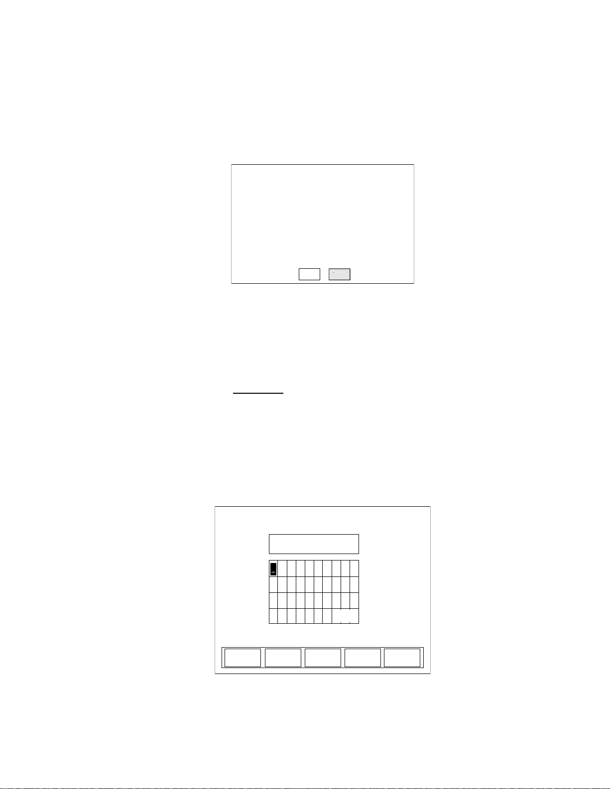
To delete a folder:
SETUP: Manage Configs
Available Configurations
Confirm deletion of folder and all contents:
Press knob to finish selection.
Cancel
Delete
C
[folder name]
TREND: Rename File
CANCEL
BACK
SPACE
SAVE
Rotate Knob
to choose letter.
Press to select.
b c j i h g f e d
k l m t s r q p o n
u v w 3 2 1 0 z y x
4
5 6 space - 9 8 7
a
[file or folder name]
/loc/[file or folder name].csv
space
1. Turn the Selection knob to highlight the name of the folder you
want to delete.
2. Press the DELETE soft key. The following confirmation
message will appear:
ancel
Figure 4-32. TREND: File Manager (Folder Deletion Confirmation)
Operation
3. Turn the Selection knob to highlight Delete.
4. Press the ENTER/SET button to delete the folder and display
the TREND: File Manager screen.
RENAME
Use this function to rename a file or folder.
1. On the TREND: File Manager screen, turn the Selection knob
to highlight the name of the file or folder you want to rename.
2. Press the RENAME soft key to display a screen similar to the
one shown in Figure 4-33.
Figure 4-33. TREND: Rename File or Folder
4 - 39
Page 76

LabMax-TOP User Manual
3. Using the BACKSPACE soft key, delete the current name.
T o delete a character at any time, use the BACKSP ACE soft key .
4. Select the first character of the new name by turning the Selection knob and then pressing the ENTER/SET button when the
desired letter or number is highlighted. The character will
appear in the blank box immediately below the screen heading.
5. Repeat step 4 until the entire name appears in the box.
6. Press the SAVE soft key to save the new name and display the
TREND: File Manager screen.
Soft Keys
There are three soft keys on the TREND: Rename File screen:
BACKSPACE, SAVE, and CANCEL.
BACKSPACE
This soft key backspaces one editable field at a time and deletes the
character that was there.
SAVE
Pressing the SAVE soft key saves whatever changes were made
since the last SAVE.
CANCEL
Pressing the CANCEL soft key discards all changes that were made
since the last SAVE and returns to the TREND: File Manager screen.
CREATE FOLDER
Use this function on the TREND: File Manager screen to create a
folder on the local drive or USB flash drive. Subfolders can be
created within a folder.
4 - 40
Page 77
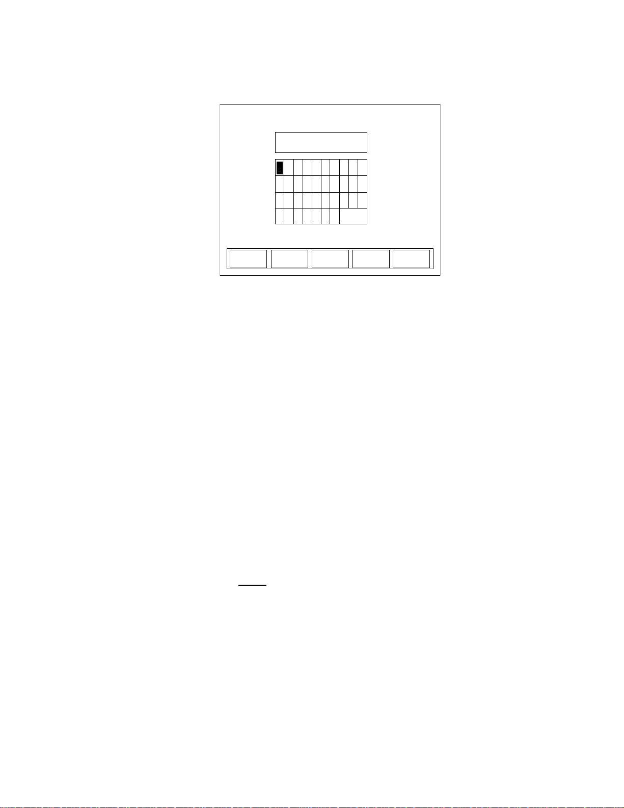
Operation
TREND: Create New Folder
CANCEL
BACK
SPACE
SAVE
Rotate Knob
to choose letter.
Press to select
b c j i h g f e d
k l m t s r q p o n
u v w 3 2 1 0 z y x
4
5 6 space - 9 8 7
a
Pressing the CREATE FOLDER soft key displays the screen shown
in Figure 4-34:
Figure 4-34. TREND: Create New Folder
Soft Keys
There are three soft keys on this screen: BACKSPACE, SAVE, and
CANCEL.
BACKSPACE
This soft key backspaces one editable field at a time and deletes the
character that was there.
SAVE
Pressing the SAVE soft key saves whatever changes were made
since the last SAVE.
CANCEL
Pressing the CANCEL soft key discards all changes that were made
since the last SAVE and returns to the TREND: File Manager screen.
EXIT
Pressing the EXIT soft key in the File Manager screen displays the
main TREND screen.
TREND Setup Use Trend Setup to select the batch duration and sampling rate:
• For thermopiles and optical sensors, the duration is in terms of
time.
• For pyroelectric sensors the duration is in terms of measured
laser pulses.
4 - 41
Page 78
LabMax-TOP User Manual
TREND: Setup
Maximum Batch Size: 466,033
Display units:
CANCEL
Watts
Duration:
Sampling rate: 10
Batch Size:
SAVE ->> <<-
100
00:00:01
samples every
(hr:min:sec)
00:00:00:10 (days:hr:min:sec)
The factory default (and maximum) sampling rate for both thermopile and optical sensors is 10 samples per second. The factory
default sampling rate for pyroelectric sensors is one sample per
measured pulse.
The ability to specify both a duration and a sampling rate offers the
flexibility of collecting data on the performance of a laser over a
desired period of time while managing the quantity of data gathered.
Example: If you are using a thermopile sensor, you could set up the
meter to log one data point per minute for seven days, resulting in
10,080 data points.
Example: If you are using a pyroelectric sensor and measuring
pulses on a 1 kHz laser, you could choose to log one point per 1000
pulses for a day, resulting in 86,400 data points.
Depending upon the sensor and display units in use, pressing the
TREND SETUP soft key on the main TREND screen displays a
screen similar to one of the following:
Figure 4-35. TREND: Setup (Thermopile and Optical Sensors)
4 - 42
Page 79
Figure 4-36. TREND: Setup (Pyroelectric Sensors)
TREND: Setup
Maximum Batch Size: 466,033
Display units:
CANCEL
Joules
Duration:
Sampling Rate: 1
Batch Size:
SAVE ->> <<-
10
0000000010 pulses
00001
samples every
pulses(s)
Soft Keys
There are four soft keys on this screen: <<-/->>(Previous/Next
directional arrows), SAVE, and CANCEL.
Operation
<<- and ->> (directional arrows)
Parameters on this screen are changed by using one of the following
procedures. The procedure that should be used depends on the type
of parameter you want to modify.
“Single” Parameters
This type of parameter—Display units, for example—has only one
modifiable field. To change a value for this type of parameter:
1. Press the ENTER/SET button until the parameter you want to
change is highlighted.
2. Turn the Selection knob to change the parameter value.
3. Press the ENTER/SET button to move to the next parameter.
4. Continue this process until the values for all the parameters are
correct.
5. Once the values for all the parameters are correct, press the
SAVE soft key to save the parameters and display the STATS
screen.
4 - 43
Page 80

LabMax-TOP User Manual
“Multiple” Parameters
This type of parameter—Duration, for example—contains several
fields that can be modified. T o change a value for this type of parameter:
1. Press the ENTER/SET button until the parameter you want to
change is highlighted.
2. Turn the Selection knob to change the parameter value.
3. Press either of the directional arrows soft keys (<<- or ->>) to
move the highlight to another value within the same parameter .
4. Repeat steps 2 and 3 until all values for that parameter are
correct.
5. Press the ENTER/SET button to move to the next parameter.
6. Once the values for all the parameters are correct, press the
SAVE soft key to save the parameters and dis play the STATS
screen.
ZERO
SAVE
Pressing the SAVE soft key saves whatever changes were made
since the last SAVE and displays the TREND screen.
CANCEL
Pressing the CANCEL soft key discards all changes that were made
since the last SAVE and displays the TREND screen.
(thermopile and optical sensors only)
Pressing the ZERO button sets the current sensor input
ZERO
If zeroing is unsuccessful—which means that the power input is too
large to null—re-zero in a more stable environment or select a
different range.The meter always zeros all available ranges for the
attached sensor . When a zero procedure is in process, no other button
events are queued or activated until the procedure ends. The zero
procedure immediately terminates if the sensor is disconnected or if
an error is encountered.
voltage as the zero baseline voltage. ZERO is not functional when the meter is in HELP mode.
Normally you should press ZERO while the laser is turned off, or
while the laser beam is blocked. If a finite power level is present at
the sensor, the instrument will attempt to null it out.
4 - 44
Page 81
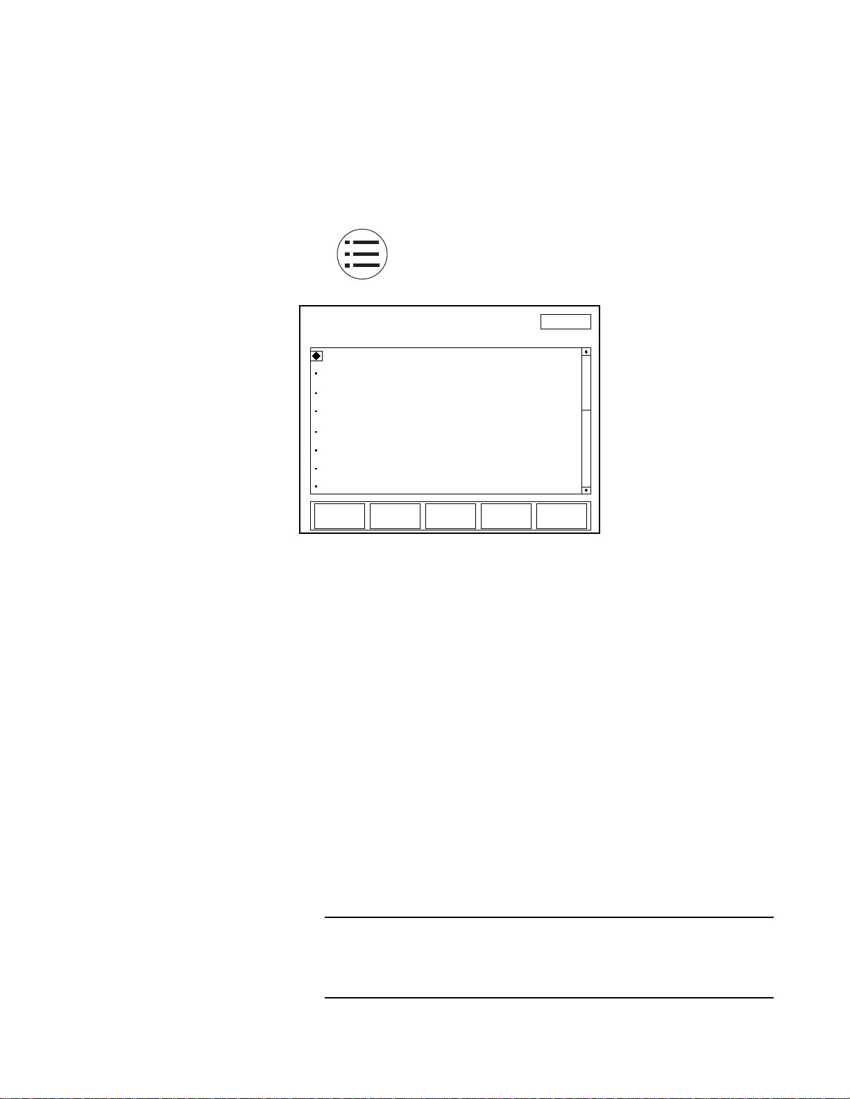
Operation
SETUP
Turn knob to select item: Press ENTER to edit
Display smoothing:
Speedup
Area correction:
Gain compensation:
Wavelength table edit
Power measure units:
Auto
OFF
OFF
Watts
SAVE
CONFIG
MANAGE
CONFIGS
EXIT
11:11 AM
Wavelength correction: 1064 nm
Resolution:
3 digits
The meter is only able to zero a finite level of offset. When zeroing
on a selected range is unsuccessful, the text “Zeroing…” is replaced
with the following error dialog: “Bad zero. The power input is too
large to null. Re-zero in a more stable environment or select a
different range.”
SETUP
Pressing the SETUP button on the front panel will
display the main SETUP screen (Figure 4-37):
Figure 4-37. SETUP
On the SETUP screen, a diamond indicator appears to the left of the
currently-selected item. To change the value of an item, turn the
Selection knob to move the indicator up or down the list and when
the bullet is next to the desired item, press the ENTER/SET button
(the Selection knob) to select that item—see Figure 3-3 (p. 3-6) for
the location of the Selection knob, all buttons, and the soft keys.
Depending on which item is selected, editing will be available either
on a list that appears to the right of the selected item, or on a new
screen that will automatically open when an item is selected.
To leave SETUP:
• Press the EXIT soft key (directly below the LCD, first key on
the right),
or
• Press the MEASURE, TUNE, or TREND button
Unless a setting is incompatible with the attached sensor, all
SETUP parameters remain in effect—even if the meter is shut
down and powered up at a later time.
4 - 45
Page 82
LabMax-TOP User Manual
SETUP
Turn knob to select item: Press ENTER to edit
Display smoothing:
Speedup
Area correction:
Gain compensation:
Auto
OFF
OFF
SAVE
CONFIG
MANAGE
CONFIGS
EXIT
11:11 AM
Wavelength table edit
Power measure units:
Watts
Wavelength correction: 1064 nm
Resolution:
3 digits
Display Smoothing
Display smoothing uses a rolling box-car average to smooth the
displayed measurement. This can be useful if individual measurement values are too noisy. Smoothing is applied to all displayed
measurements on all screens. In the case of quadrant position-sensing thermopile sensors, display smoothing is applied to the
position indicator within the bulls eye.
Figure 4-38. SETUP: Display Smoothing
Available values: AUTO (factory default), MANUAL, and OFF.
To change a value:
1. On the main SETUP screen, turn the Selection knob to move
the diamond indicator to Display smoothing.
2. Press the ENTER/SET button to highlight the editable field
(Figure 4-38).
3. Turn the Selection knob to change the value.
4 - 46
Page 83
Operation
01
SETUP
Turn knob to change value and press ENTER.
Display Smoothing: Manual
EXIT
secs
22.5W
<<-
->>
SETUP
Turn knob to change value and press ENTER.
Display Smoothing:
TRIGGER
Manual
EXIT
pulses
032
5.06mW
<<-
->>
4. Press the ENTER/SET button to save the value and return to
the main SETUP screen.
If you select Manual as the Display Smoothing value, pressing
the ENTER/SET button will display either the screen shown in
Figure 4-39 (for thermopile and optical sensors) or the screen
shown in Figure 4-40 (for pyroelectric sensors). This allows the
results of smoothing the setting to be observed on the live
measurement during setup. Continue to step 5.
Figure 4-39. SETUP: Display Smoothing (Thermopile and Optical Sensors - Manual Mode)
Figure 4-40. SETUP: Display Smoothing (Pyroelectric Sensors - Manual Mode)
4 - 47
Page 84
LabMax-TOP User Manual
SETUP: Speedup
Turn knob to change value and press ENTER.
Tune:
EXIT
ON
Analog Out: ON
Measure: ON
Data Store: ON
Turn the Selection knob to change the number of seconds (thermopile and optical sensors) or pulses (pyroelectric sensors).The direc-
tional arrow soft keys (<<- and ->>) can be used to move the
highlight to a different digit before using the Selection knob to
change the value.
5. Press the ENTER/SET button—or the EXIT soft key—to save
the value and exit Display Smoothing mode.
Press the EXIT soft key at any time to save all current values and
return to the main SETUP screen.
Speedup
(thermopile sensors only) This command selects the speedup mode
for the host interface data output.
Figure 4-41. SETUP: Speedup
Available values: ON (factory default) and OFF.
Speedup can be turned ON or OFF for the following features: Tune,
Measure, Analog Out, and Data Store.
To change a value:
1. On the main SETUP screen, turn the Selection knob to move
the diamond indicator to Speedup.
2. Press the ENTER/SET button to Display the SETUP: Speedup
screen (Figure 4-41).
4 - 48
Page 85
Operation
SETUP
Turn knob to select item: Press ENTER to edit
Display smoothing:
Speedup
Area correction:
Gain compensation:
Auto
ON
OFF
EXIT
11:11 AM
001.00 cm
2
Wavelength table edit
Power measure units:
Watts
Wavelength correction: 1064 nm
Resolution:
3 digits
<<- ->>
cm
2
3. Press the ENTER/SET button to highlight the value of the
feature you want to change.
4. Turn the Selection knob to change the value.
5. Press the ENTER/SET button to lock in the current value and
move the highlight to the next editable field.
Pressing the ENTER/SET button after highlighting Data Store,
or pressing the EXIT soft key at any time will save all the
locked-in values, exit Speedup mode, and return to the main
SETUP screen.
Area Correction
Area Correction allows the measurement value to be displayed in
terms of a unit area. The measured value (in watts or joules) is
divided by the area entered here. This mode is most commonly used
in processes where the energy density (fluence) or power
density—rather than the absolute energy or power—is of paramount
importance. Typically in these applications the sensor aperture is
completely flooded by laser light, and the sensor aperture is entered
here.
Figure 4-42. SETUP: Area Correction
Available values: ON and OFF (factory default).
Available range: 0.01 to 500.00 cm2 or 0.1 to 250 mm.
4 - 49
Page 86

LabMax-TOP User Manual
Available units: cm2 and mm. The area can be entered in terms of
area in square centimeters or in terms of the diameter of the active
area in millimeters. When entering the active area in terms of the
diameter, the active area must be circular.
Most Coherent sensors utilize circular apertures, so the ability
to enter the active area in terms of the diameter in millimeters is
often an easier process than calculating the area yourself.
To change a value:
1. On the main SETUP screen, turn the Selection knob to move
the diamond indicator to Area Correction.
2. Press the ENTER/SET button to highlight the editable field
(Figure 4-42).
3. Turn the Selection knob to change the value.
4. Press the ENTER/SET button to save the value.
If you select ON as the Area Correction value, pressing the
ENTER/SET button will display the range field (shown as
001.00 in Figure 4-42, above) and the unit of measurement (cm
in Figure 4-42). Continue to step 5.
5. Turn the Selection knob to change the range value.
The directional arrow soft keys (<<- and ->>) can be used to
move the highlight to a different digit before using the Selection
knob to change the value.
6. Press the ENTER/SET button to save the value and exit Area
Correction mode.
Pressing the EXIT soft key at any time while in SETUP will leave
the SETUP program.
2
To change the unit of measurement:
1. On the main SETUP screen, turn the Selection knob to move
the diamond indicator to Area Correction.
4 - 50
Page 87

Operation
2. Press the ENTER/SET button to highlight the first field and set
Area Correction to ON.
3. Press the ENTER/SET button to move the highlight to the
Area Correction value field. This action will display the Unit
soft key (next to EXIT at the bottom of the LCD).
4. Toggle the Unit soft key to select either cm2 or mm as the unit
of measurement.
5. Press the ENTER/SET button to save the value.
If there is a diameter in the sensor EEPROM, it is used as the
default when the meter powers up; otherwise, the last-entered
value is used.
Gain Compensation
Gain Compensation lets the user adjust the measured values based
upon the gain factor entered here. Measurement values are multiplied by the gain factor.
Gain compensation has several uses:
• Accounting for filters or other optical attenuators upstream in
the beam path.
• Measuring a small pick-off beam from a beamsplitter and
wanting to calibrate the meter to display the power or energy
of the main beam.
4 - 51
Page 88
LabMax-TOP User Manual
SETUP
Turn knob to select item: Press ENTER to edit
Display smoothing:
Speedup
Area correction:
Gain compensation:
Auto
OFF
ON
EXIT
11:11 AM
000001.000
Wavelength table edit
Power measure units:
Watts
Wavelength correction: 1064 nm
Resolution:
3 digits
<<- ->>
• Self-calibrating a meter and sensor system, based upon the
your own calibration system.
If you are using gain as a calibration factor, be sure to save a
custom configuration—refer to “Save Current Config”
(p. 4-69). It is possible to save multiple configurations for
multiple sensor serial numbers, which allows you to recall
particular configurations by pressing the MANAGE CONFIGS
soft key and then selecting a particular configuration file.
Figure 4-43. SETUP: Gain Compensation
Available values: ON and OFF (factory default).
Available range: 0.001 to 100000
To change a value:
1. On the main SETUP screen, turn the Selection knob to move
the diamond indicator to Gain Compensation.
2. Press the ENTER/SET button to highlight the first field.
3. Turn the Selection knob and display ON in the Gain Compensation field and then press the ENTER/SET button to move the
highlight to the Gain Compensation value field (shown as
000001.000 in Figure 4-43).
4. Turn the Selection knob to change the value.
The directional arrow soft keys (<<- and ->>) can be used to
move the highlight to a different digit before using the Selection
knob to change the value.
4 - 52
Page 89
Operation
SETUP
Turn knob to select item: Press ENTER to edit
Display smoothing:
Speedup
Area correction:
Gain compensation:
Auto
OFF
OFF
EXIT
11:11 AM
SAVE
CONFIG
MANAGE
CONFIGS
Wavelength correction:
Wavelength table edit
Power measure units:
OFF
1064 nm
1064 nm
Resolution:
3 digits
5. Press the ENTER/SET button to save the value and exit Gain
Compensation mode.
Pressing the EXIT soft key at any time while in SETUP will leave
the SETUP program.
Wavelength Correction
Wavelength Correction lets the user select the sensor wavelength.
Figure 4-44. SETUP: Wavelength Correction
Available values: OFF and wavelengths that are available for the
attached sensor.
To change a value:
1. On the main SETUP screen, turn the Selection knob to move
the diamond indicator to Wavelength Correction.
2. Press the ENTER/SET button to display a dropdown list of
available wavelengths (similar to the list shown in
Figure 4-44).
3. Turn the Selection knob to highlight the desired value.
4. Press the ENTER/SET button to save the value and exit W avelength Correction mode.
4 - 53
Page 90
LabMax-TOP User Manual
SETUP
Display smoothing:
Speedup
Area correction:
Gain compensation:
Auto
OFF
OFF
EXIT
11:11 AM
SAVE
CONFIG
MANAGE
CONFIGS
Wavelength table edit
Power measure units:
Watts
Wavelength correction: 1064 nm
Resolution:
3 digits
Turn knob to select item: Press ENTER to edit
Wavelength Table
Edit
This item lets the user add or delete sensor wavelengths.
Figure 4-45. SETUP: Wavelength Table Edit
Available values: All available pre-set wavelengths.
To access the Edit Wavelength Table screen:
1. On the main SETUP screen, turn the Selection knob to move
the diamond indicator to W avelength Table Edit (Figure 4-45).
2. Press the ENTER/SET button to display the SETUP: Edit
Wavelength Table screen. From this screen, you can add or
delete a wavelength, as explained next.
On this screen, wavelengths below 1000 nm display in terms of
nanometers, and wavelengths above 1000 nm display in terms of
microns.
4 - 54
Page 91
Adding a Wavelength
SETUP: Edit Wavelength Table
Turn knob to select wavelength:
EXIT
ADD
193 nm
266 nm
532 nm
1,064 μm
10,600 μm
248 nm
Note: current
operating
wavelength
is not editable.
Current Sensor
Min: 248 nm
Op: 1.064 μm
Cal: 514 nm
Max: 10,600 μm
SETUP: Edit Wavelength Table
Turn knob to select wavelength:
CANCEL
193 nm
266 nm
532 nm
1,064 μm
10,600 μm
248 nm
Note: current
operating
wavelength
is not editable.
Current Sensor
Min: 248 nm
Op: 1.064 μm
Cal: 514 nm
Max: 10.600 μm
00337 nm
<<-
->>
Operation
DELETE
Figure 4-46. SETUP: Edit Wavelength Table
From the SETUP: Edit Wavelength Table screen (Figure 4-46):
1. Press the ADD soft key.
2. Turn the Selection knob to display a new wavelength. The
wavelength will appear at the bottom of the dropdown list (in
the following example, the new wavelength is 00337 nm).
The directional arrow soft keys (<<- and ->>) can be used to
move the highlight to a different digit before using the Selection
knob to change the value.
Figure 4-47. SETUP: Edit Wavelength Table (Adding a Wavelength)
3. Press the ENTER/SET button to add the new wavelength to the
dropdown list.
4 - 55
Page 92
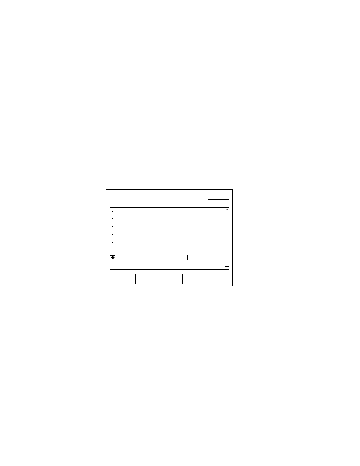
LabMax-TOP User Manual
SETUP
Turn knob to select item: Press ENTER to edit
Display smoothing:
Speedup
Area correction:
Gain compensation:
Auto
OFF
OFF
SAVE
CONFIG
MANAGE
CONFIGS
EXIT
11:11 AM
Wavelength correction:
Wavelength table edit
Power measure units:
1064 nm
Watts
Resolution:
3 digits
4. Press the EXIT soft key to exit Edit Wavelength Table mode
and return to the main SETUP screen.
Deleting a Wavelength
Power Measure Units
From the SETUP: Edit Wavelength Table screen (Figure 4-46):
1. Turn the Selection knob to highlight the wavelength you want
to delete.
2. Press the DELETE soft key to remove the wavelength from the
dropdown list.
3. Press the EXIT soft key to exit Edit Wavelength Table mode
and return to the main SETUP screen.
Figure 4-48. SETUP: Power Measure Units
Available values: Watts (factory default) and dBm.
To change a value:
1. On the main SETUP screen, turn the Selection knob to move
the diamond indicator to Power Measure Units.
2. Press the ENTER/SET button to highlight the value field
(Figure 4-48).
3. Turn the Selection knob to change the value.
4. Press the ENTER/SET button to save the value and exit Power
Measure Units mode.
4 - 56
Page 93
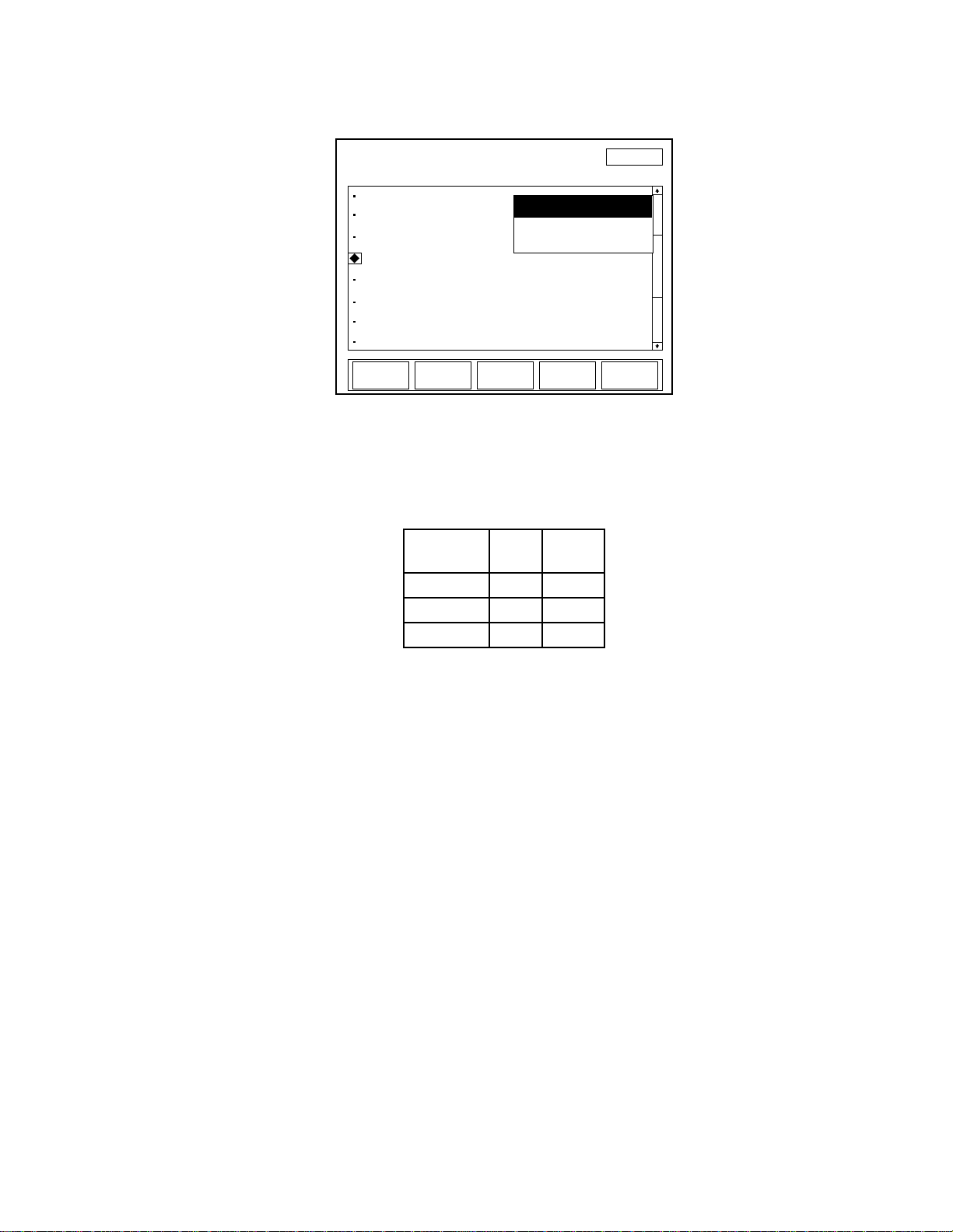
Resolution
SETUP
Turn knob to select item: Press ENTER to edit
Wavelength correction:
Wavelength table edit
Power measure units:
Resolution:
Analog output:
Trigger
Communications
Date/time:
1064 nm
Watts
3 digits
2 V
07-10-07
SAVE
CONFIG
MANAGE
CONFIGS
EXIT
11:11 AM
Internal
USB
4 digits
3 digits
5 digits
Operation
Figure 4-49. SETUP: Resolution
Available values: See the following table:
Table 4-3. Sensor Resolution Ranges
Sensor
Type
Range
Factory
Default
Thermopile 3, 4, 5 3
Optical 3, 4, 5 3
Pyroelectric 3, 4 3
To change a value:
1. On the main SETUP screen, turn the Selection knob to move
the diamond indicator to Resolution.
2. Press the ENTER/SET button to display a dropdown list of
available resolutions (similar to the list shown in Figure 4-49).
3. Turn the Selection knob to highlight the desired value.
4. Press the ENTER/SET button to save the value and exit Resolution mode.
4 - 57
Page 94
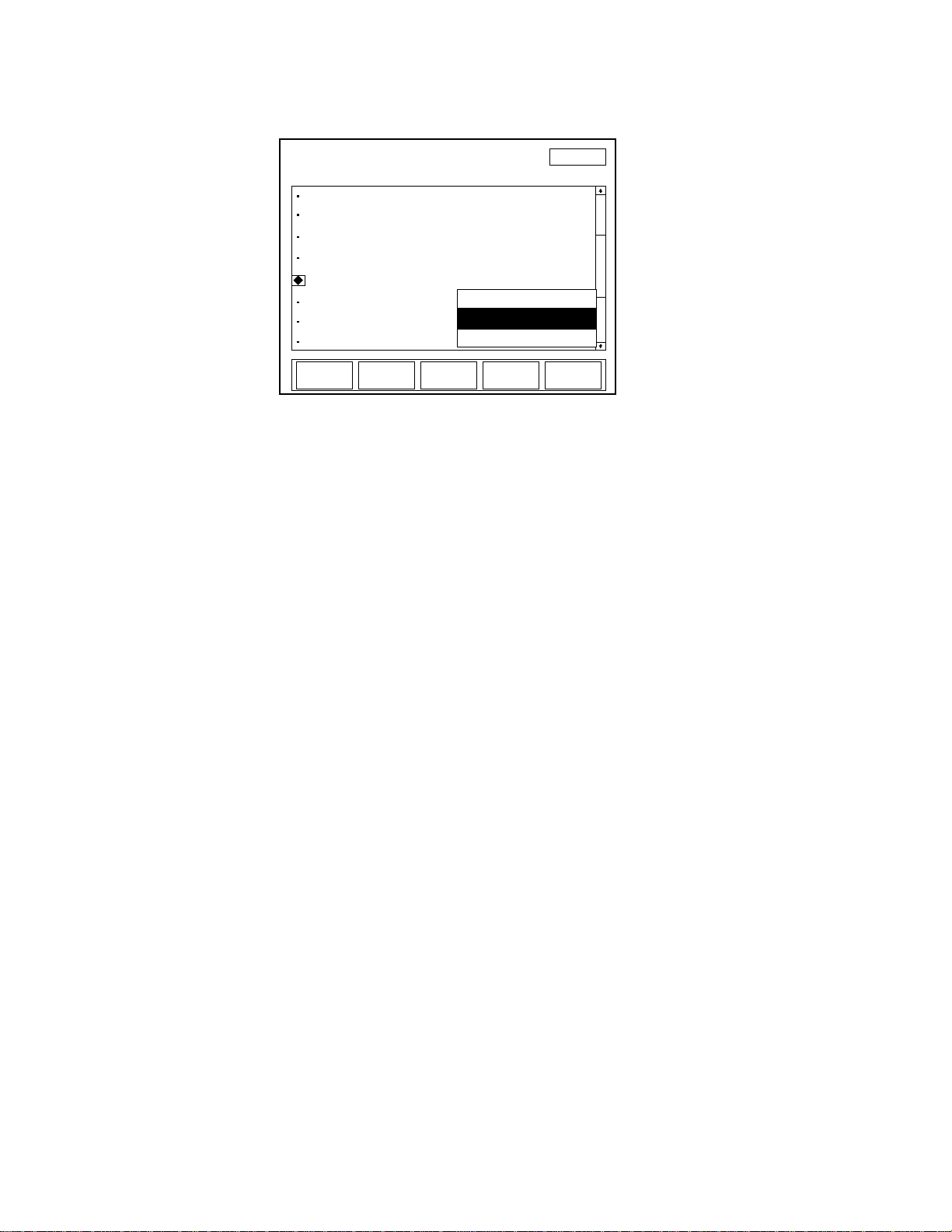
LabMax-TOP User Manual
SETUP
Turn knob to select item: Press ENTER to edit
Wavelength correction:
Wavelength table edit
Power measure units:
Resolution:
Analog output:
Trigger
Communications
Date/time:
1064 nm
Watts
3 digits
2V
07-10-07
SAVE
CONFIG
MANAGE
CONFIGS
EXIT
11:11 AM
1V
4V
2V
Analog Output
Figure 4-50. SETUP: Analog Output
Available values: 1, 2 (factory default), and 4V.
To change a value:
Trigger
1. On the main SETUP screen, turn the Selection knob to move
the diamond indicator to Analog Output.
2. Press the ENTER/SET button to display a dropdown list of
available voltages (similar to the list shown in Figure 4-50).
3. Turn the Selection knob to highlight the desired value.
4. Press the ENTER/SET button to save the value and exit
Analog Output mode.
(pyroelectric sensors only) This is where the trigger source—either
internal or external—is defined. If the laser has a trigger output, use
external triggering to provide the most accurate readings. Since the
meter is not looking for trigger events itself, the measured value will
be an actual laser pulse. Using external trigger also allows monitoring the missed pulses in Statistics mode, which can be useful
when diagnosing laser problems.
4 - 58
Page 95
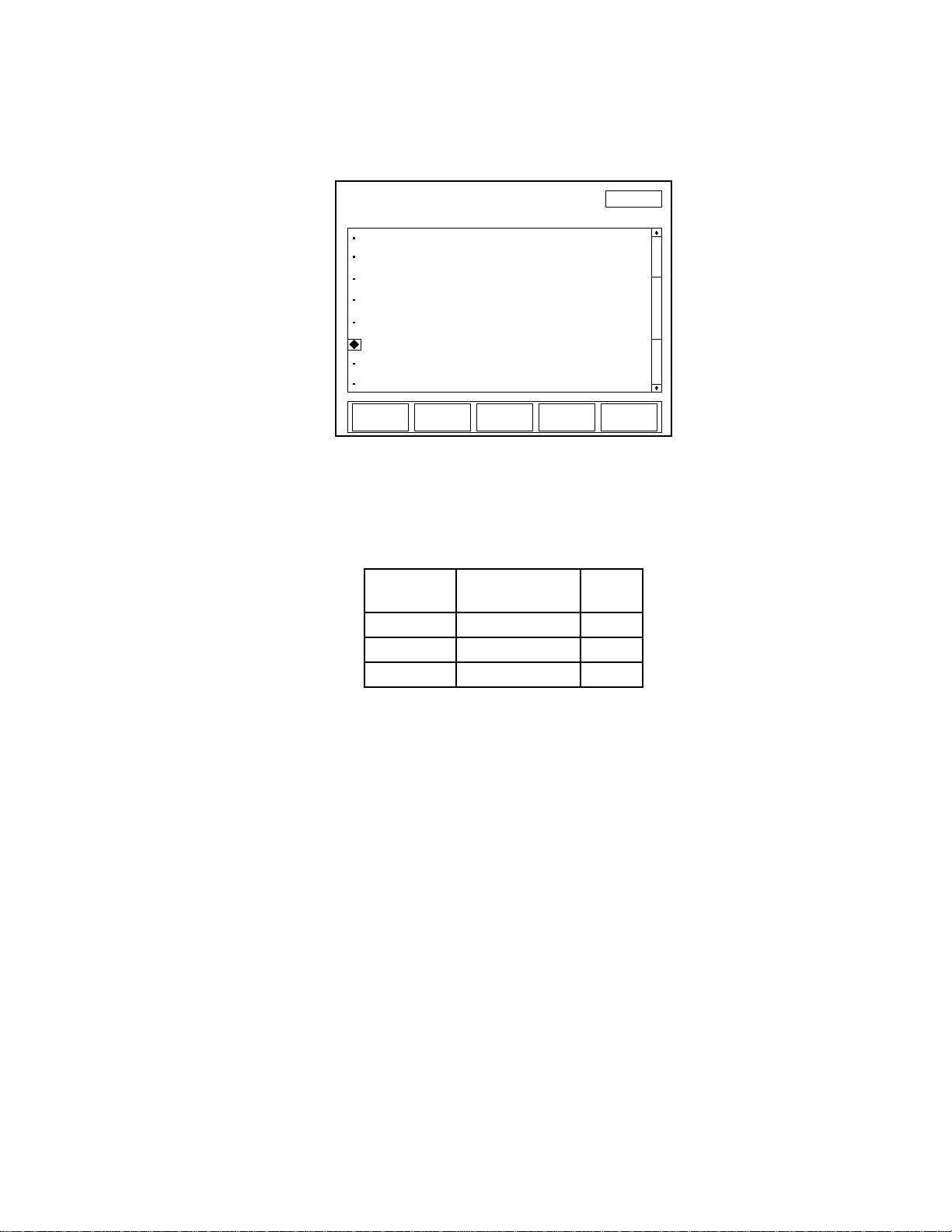
Operation
SETUP
Turn knob to select item: Press ENTER to edit
Wavelength correction:
Wavelength table edit
Power measure units:
Resolution:
Analog output:
Trigger
Communications
Date/time:
1064 nm
Watts
3 digits
2V
07-10-07
SAVE
CONFIG
MANAGE
CONFIGS
EXIT
11:11 AM
USB
Internal
External triggers can be selected as negative or positive, and a
trigger delay can be entered if the laser pulse occurs after the
external trigger event.
Figure 4-51. SETUP: Trigger
Available values: See the following table:
Table 4-4. Trigger Range and Factory Defaults
Setting Range
Source Internal, External Internal
Delay 0 to 1000 µs 0 µs
Trigger Edge Positive, Negative Positive
To change a value:
1. On the main SETUP screen, turn the Selection knob to move
the diamond indicator to Trigger (Figure 4-51).
4 - 59
Factory
Default
Page 96
LabMax-TOP User Manual
SETUP: Trigger
Turn knob to change value and press ENTER.
Source:
EXIT
External
Delay:
Trigger edge: Positive
0000 μs
<<- ->>
Figure 4-52. SETUP: Trigger (Changing the Values)
2. Press the ENTER/SET button to display the SETUP: Trigger
screen (Figure 4-52).
3. Turn the Selection knob to change the value of the source.
4. If you select Internal as the source, press the EXIT soft key to
save the value, exit Trigger mode, and return to the main
SETUP screen; there are no other option selections available.
Selecting External as the source value (as shown in
Figure 4-52) will display editable fields next to Delay and
Trigger Edge. Continue to step 5.
5. Press the ENTER/SET button to move the highlight to the
Delay field.
6. Turn the Selection knob to change the value.
The directional arrow soft keys (<<- and ->>) can be used to
move the highlight to a different digit within the Delay field
before using the Selection knob to change the value.
7. Press the ENTER/SET button to lock in the Delay value and
move the highlight to Trigger Edge field.
8. Turn the Selection knob to select a value.
9. Press the EXIT soft key to save all the Trigger values, exit
Trigger mode, and return to the main SETUP screen.
4 - 60
Page 97
Operation
SETUP
Turn knob to select item: Press ENTER to edit
Wavelength correction:
Wavelength table edit
Power measure units:
Resolution:
Analog output:
Trigger
Communications
Date/time:
1064 nm
Watts
3 digits
2V
07-10-07
SAVE
CONFIG
MANAGE
CONFIGS
EXIT
11:11 AM
USB
Internal
Communications
Use Communications to define the host interface type that will be
used to communicate with a PC. The factory default is USB. If you
cannot communicate with the meter via a PC, the most likely reason
is that the Communications type is not set correctly on this screen.
Figure 4-53. SETUP: Communications
Available values: See the following table:
Table 4-5. Communication Values and Factory Defaults
Setting
Label
Values
Host USB, GPIB, RS-232 USB
RS-232 Baud Rate 9600, 19200, 38400, 57600, 115200 19200
RS-232 Stop Bits 1, 2 1
RS-232 Parity None, Odd, Even None
RS-232 Flow Control None, Xon/Xoff None
GPIB Id 1 to 30 1
Factory
Default
To change a value:
1. On the main SETUP screen, turn the Selection knob to move
the diamond indicator to Communications (Figure 4-53).
4 - 61
Page 98
LabMax-TOP User Manual
SETUP: Communications
Turn knob to change value and press ENTER.
EXIT
RS-232 Baud rate: 19200
RS-232 Parity: None
RS-232 Stop bits: 1
RS-232 Flow control: None
Host: RS-232
GPIB Id:
Figure 4-54. SETUP: Communications (Changing the Values)
2. Press the ENTER/SET button to Display the SETUP: Communications screen (Figure 4-54).
3. Turn the Selection knob to change a value.
Selecting RS-232 or GPIB as the Host value will display the editable fields shown in Figure 4-54. Continue to step 4.
4. Press the ENTER/SET button to lock in the value and move
the highlight to the next editable field (except for USB, which
does not have other editable fields).
5. Continue the process until all the values on the screen are
correct.
6. Press the EXIT soft key to save the values and exit Communications mode.
4 - 62
Page 99
Operation
SETUP
Turn knob to select item: Press ENTER to edit
Wavelength correction:
Wavelength table edit
Power measure units:
Resolution:
Analog output:
Trigger
Communications
Date/time:
1064 nm
Watts
3 digits
2V
07-10-07
SAVE
CONFIG
MANAGE
CONFIGS
EXIT
11:11 AM
USB
Internal
Date/Time
Enter the date and time here. Date/time is only used for naming files
and for date and time information within the Microsoft Windows
operating system file manager.
Figure 4-55. SETUP: Date/Time
Available values: See the following table:
Table 4-6. Date/Time Ranges and Factory Defaults
Setting Range Factory Default
Date Format
mm-dd-yy
dd-mm-yy
mm-dd-yy
Date Limits of Data function Initially set during Factory testing
Time hr:min (24-hour format) Initially set during Factory testing
To change a value:
1. On the main SETUP screen, turn the Selection knob to move
the diamond indicator to Date/Time (Figure 4-55).
4 - 63
Page 100
LabMax-TOP User Manual
SETUP: Date
Turn knob to change value and press ENTER.
EXIT
Date Format: mm-dd-yy
Time: 11 : 11
Date: 2007 10 07
11:11 AM
Figure 4-56. SETUP: Date/Time (Changing the Values)
2. Press the ENTER/SET button to Display the SETUP: Date
screen (Figure 4-56).
3. Turn the Selection knob to change a value.
4. Press the ENTER/SET button to lock in the value and move to
the next editable field.
5. Continue the process until all the values on the screen are
correct.
6. Press the EXIT soft key to save the values and exit Date mode.
Pressing the EXIT soft key at any time will save the current
values and return to the main SETUP screen.
4 - 64
 Loading...