

Page 1

User Manual
TM
LabMax-Pro SSIM
Laser Power Meter
Page 2

Page 3

User Manual
LabMax-Pro SIMM
Laser Power Meter
27650 SW 95th Ave.
Wilsonville, OR 97070
Page 4

LabMax-Pro SSIM User Manual
This document is copyrighted with all rights reserved. Under the copyright
laws, this document may not be copied in whole or in part or repr oduced in
any other media without the exp ress written perm ission of Coher ent, Inc.
Permitted copies must carry the same proprietary and copyright notices as
were affixed to the original. This exception does not allow copies to be
made for others, whether or not sold, but all the material purchased may
be sold, given, or loaned to another person. Under the law, copying
includes translation into another language.
Coherent, the Coherent Logo, and LabMax are trademarks or registered
trademarks of Coherent, Inc. All other trademarks or registered
trademarks are the property of their respective owners.
Patents referenced in this document were active as of the printing date of
the manual (see last page for date). The patents referenced herein may
have expired. Y ou are advised to check to see if the patents are still active:
http://portal.uspto.gov/external/portal/pair
Every effort has been made to ensure th at the dat a given in this docume nt
is accurate. The information, figures, tables, specifications and schematics
contained herein are subject to change without notice. Coherent makes no
warranty or representation, either expresse d or implied with respect to this
document. In no event will Coherent be liable for any direct, indirect,
special, incidental or consequential damages resulting from any defects in
its documentation.
.
Technical Support
In the US:
Should you experience any difficulties with your product or need any
technical information, please visit our website: www.Coherent.com
Additional support can be obtained by contacting our Technical Support
Hotline at 1.800.367.7890 (1.408.764.4557 outside the U.S.), or e-mail
the clock (except U.S. holidays and company shutdowns).
If you call outside our office hours, your call will be taken by our answering
system and will be returned when the office reopens.
If there are technical difficulties with your laser that cannot be resolved by
support mechanisms outlined above, e-mail, or telephone Coherent
Technical Support with a description of the problem and the corrective
steps attempted. When communicating with our Technical Support
Department via the web or telephone, the Support Engineer r esponding to
your request will require the model and Laser Head serial number of your
laser system.
Outside the US:
If you are located outside the U.S., visit our website for technical
assistance or contact our local service representative. Representative
phone numbers and addresses can be found on the Coherent website:
www.Coherent.com
.
. T elephone cover age is available around
.
Coherent provides telephone and web technical assist ance as a service to
its customers and assumes no liability thereby for any injury or damage
that may occur contemporaneous with such services. These support
services do not affect, under any circumstan ces, the terms of any warranty
agreement between Coherent and the buyer. Operation of any Coherent
laser with any of its interlocks defeated is always at the operator's o wn risk
ii
Page 5

Table of Contents
TABLE OF CONTENTS
Signal Words and Symbols in this Manual.......................................................................... vii
Signal Words............................................................................................................... vii
Symbols ..................................................................................................................... viii
Preface .................................................................................................................................. ix
RoHS Compliance ................................................................................................................ ix
Export Control Laws Compliance ........................................................................................ ix
Publication Updates.............................................................................................................. ix
Firmware Updates................................................................................................................. ix
Section One: Safety......................................................................................................... 1-1
Waste Electrical and Electronic Equipment (WEEE, 2002)............................................... 1-2
Declaration of Conformity.................................................................................................. 1-2
Section Two: Software Installation and Quick Start................................. 2-1
Software Installation...........................................................................................................2-1
Initial Setup Instructions..................................................................................................... 2-1
Taking a Standard-Speed Measurement.............................................................................. 2-3
Taking a High-Speed Measurement.................................................................................... 2-6
Taking a Snapshot Measurement ........................................................................................2-9
Taking a Pyroelectric Energy Measurement..................................................................... 2-15
Setting up the Cursor Feature ........................................................................................... 2-18
Section Three: Description.........................................................................................3-1
Introduction......................................................................................................................... 3-1
Operating Mode Overview ................................................................................................. 3-2
Standard-Speed Mode................................................................................................ 3-2
High-Speed Mode...................................................................................................... 3-2
Snapshot Mode .......................................................................................................... 3-3
Product Features ................................................................................................................. 3-4
LabMax-Pro PC Software Features.................................................................................... 3-5
Thermopile and PowerMax-Pro Sensor Technology.......................................................... 3-6
Thermopile Sensors ................................................................................................... 3-6
PowerMax-Pro Sensors.............................................................................................. 3-7
Applying Wavelength Compensation Accuracy................................................................. 3-8
Wavelength Compensation Accuracy........................................................................ 3-9
Section Four: Operation.............................................................................................. 4-1
Hardware............................................................................................................................. 4-1
Sensor Compatibility ..........................................................................................................4-2
USB/RS-232 ....................................................................................................................... 4-2
Power Supply...................................................................................................................... 4-2
External Trigger Input......................................................................................................... 4-2
External Trigger Output...................................................................................................... 4-4
iii
Page 6

LabMax-Pro SSIM User Manual
Analog Output..................................................................................................................... 4-4
PC Application.................................................................................................................... 4-5
Section Five: Host Interface......................................................................................5-1
Special Considerations........................................................................................................ 5-1
Message Terminators .................................................................................................5-1
Messages Received by the Meter...................................................................... 5-1
Messages Sent by the Meter ............................................................................. 5-1
Using the RS-232 Interface........................................................................................ 5-2
Data Flow Control ............................................................................................ 5-2
Baud Rate and Other Communication Settings................................................ 5-2
Using the USB Interface............................................................................................ 5-2
Syntax and Notation Conventions ............................................................................. 5-2
Host Command Quick Reference .......................................................................................5-3
Commands and Queries...................................................................................................... 5-6
SCPI Common Commands........................................................................................ 5-6
Reset Command - *RST................................................................................... 5-6
Identification Query - *IDN?............................................................................ 5-6
System Options.......................................................................................................... 5-7
System Type...................................................................................................... 5-7
System Status.................................................................................................... 5-7
System Fault ..................................................................................................... 5-8
System Restore ................................................................................................. 5-8
System Sync...................................................................................................... 5-8
Communications........................................................................................................ 5-9
Message Handshaking ...................................................................................... 5-9
Error Record Reporting and Collection..................................................................... 5-9
Error Count Query .......................................................................................... 5-11
Error Query..................................................................................................... 5-11
All Error Query............................................................................................... 5-11
All Error Clear ................................................................................................ 5-11
Measurement Setup and Control.............................................................................. 5-12
Measurement Mode Select.............................................................................. 5-12
Measurement Data Snapshot Mode Select ..................................................... 5-12
Measurement Data Acquisition Source Select................................................ 5-13
Measurement Data Acquisition Source List Query........................................ 5-13
Speedup........................................................................................................... 5-13
Area Correction............................................................................................... 5-13
Analog Output Full Scale Voltage .................................................................. 5-14
Data Smoothing .............................................................................................. 5-14
Wavelength Correction ...................................................................................5-14
Gain Compensation......................................................................................... 5-15
Probe Zero....................................................................................................... 5-16
Pulsed Thermopile Joules Trigger Level........................................................ 5-16
Pulse Detection Measurement Window.......................................................... 5-16
Sample Variable Decimation .......................................................................... 5-17
Range Select ................................................................................................... 5-17
iv
Page 7

Table of Contents
Data Item Select.............................................................................................. 5-18
Measurement Data Format.............................................................................. 5-19
Trigger Parameters.......................................................................................... 5-20
Measurement Data Collection ................................................................................. 5-22
Last Data Record Query ................................................................................. 5-22
Data Gating..................................................................................................... 5-23
Meter and Probe Device Information ...................................................................... 5-23
Meter............................................................................................................... 5-23
Probe............................................................................................................... 5-25
Persistent Parameters........................................................................................................ 5-28
Host Interface Glossary .................................................................................................... 5-28
Section Six: Calibration and Warranty.............................................................6-1
Calibration .......................................................................................................................... 6-1
Coherent Calibration Facilities and Capabilities................................................................ 6-1
Limited Warranty................................................................................................................6-2
Extended Warranty.............................................................................................................. 6-2
Warranty Limitations ..........................................................................................................6-3
Obtaining Service ...............................................................................................................6-3
Product Shipping Instructions............................................................................................. 6-4
Appendix A: Specifications....................................................................................... A-1
Meter Specifications .......................................................................................................... A-1
Persistent Parameters......................................................................................................... A-2
Appendix B: Errors........................................................................................................B-1
Meter and Sensor Errors .....................................................................................................B-1
Index................................................................................................................................. Index-1
LIST OF FIGURES
1-1. Waste Electrical and Electronic Equipment Label........................................................... 1-2
3-1. Example of Detail Available When Using High-Speed Mode ........................................ 3-2
3-2. Example of Detail Available When Using Snapshot Mode............................................. 3-3
3-3. Construction of a Traditional Radial Thermopile............................................................ 3-6
3-4. Basic Configuration of a PowerMax-Pro Sensor............................................................. 3-7
3-5. The Rise Time of a Typical Mid-power Thermopile (30W) Compared with the
PowerMax-Pro........................................................................................................... 3-8
3-6. RV Spectral Correction for Thermal Sensors (Normalized to Calibration
Wavelength)............................................................................................................... 3-9
3-7. RV Spectral Correction for PowerMax-Pro Sensors (Normalized to Calibration
Wavelength)............................................................................................................. 3-10
v
Page 8

LabMax-Pro SSIM User Manual
4-1. Meter Front Panel ............................................................................................................ 4-1
4-2. Meter Back Panel............................................................................................................. 4-1
4-3. External Trigger Input Circuitry...................................................................................... 4-2
4-4. Example Trigger Output Screens..................................................................................... 4-3
4-5. Boosting Source Current of Triggering Device............................................................... 4-3
4-6. External Trigger Output Circuitry....................................................................................4-4
4-7. Location of PC Application Help Button ........................................................................ 4-5
LIST OF TABLES
3-1. Wavelength Compensation Accuracy............................................................................ 3-10
5-1. RS-232 Communication Settings..................................................................................... 5-2
5-2. Host Command Quick Reference ....................................................................................5-3
5-3. Status Code Bit Definitions ............................................................................................. 5-7
5-4. Fault Code Bit Definitions............................................................................................... 5-8
5-5. Error Codes and Description Strings .............................................................................5-10
5-6. Data Item Selections for Measurement Data Record..................................................... 5-18
5-7. Measurement Data Record Format, ASCII.................................................................... 5-19
5-8. FLAG Bit Definitions.................................................................................................... 5-20
5-9. Persistent Parameters..................................................................................................... 5-28
6-1. Coherent Service Centers................................................................................................. 6-4
A-1. Specifications.................................................................................................................. A-1
B-1. Meter and Sensor Errors ..................................................................................................B-1
vi
Page 9

Table of Contents
Signal Words and Symbols in this Manual
Signal Words
This documentation may contain sections in which particular
hazards are defined or special attention is drawn to particular conditions. These sections are indicated with signal words in accordance
with ANSI Z-535.6 and safety symbols (pictorial hazard alerts) in
accordance with ANSI Z-535.3 and ISO 7010.
Four signal words are used in this documentation: DANGER,
WARNING, CAUTION and NOTICE.
The signal words DANGER, WARNING and CAUTION designate the degree or level of hazard when there is the risk of injury:
DANGER!
Indicates a hazardous situation that, if not avoided, will result in
death or serious injury. This signal word is to be limited to the
most extreme situations.
WARNING!
Indicates a hazardous situation that, if not avoided, could result
in death or serious injury.
CAUTION!
Indicates a hazardous situation that, if not avoided, could result
in minor or moderate injury.
The signal word “NOTICE” is used when there is the risk of property damage:
NOTICE!
Indicates information considered important, but not hazardrelated.
Messages relating to hazards that could result in both personal injury
and property damage are considered safety messages and not property damage messages.
vii
Page 10
LabMax-Pro SSIM User Manual
Symbols
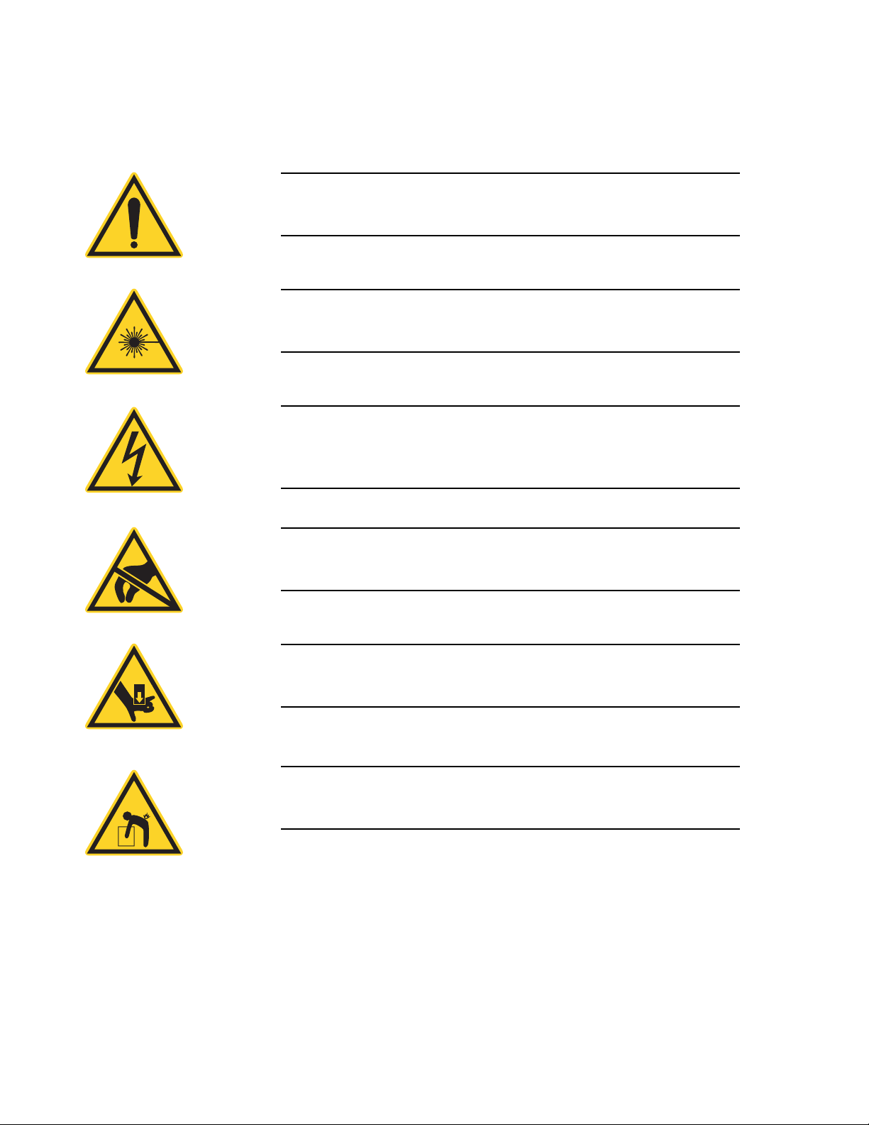
The signal words DANGER, WARNING, and CAUTION are
always emphasized with a safety symbol that indicates a special
hazard, regardless of the hazard level:
This symbol is intended to alert the operator to the presence of
important operating and maintenance instructions.
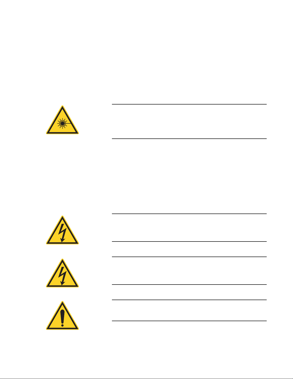
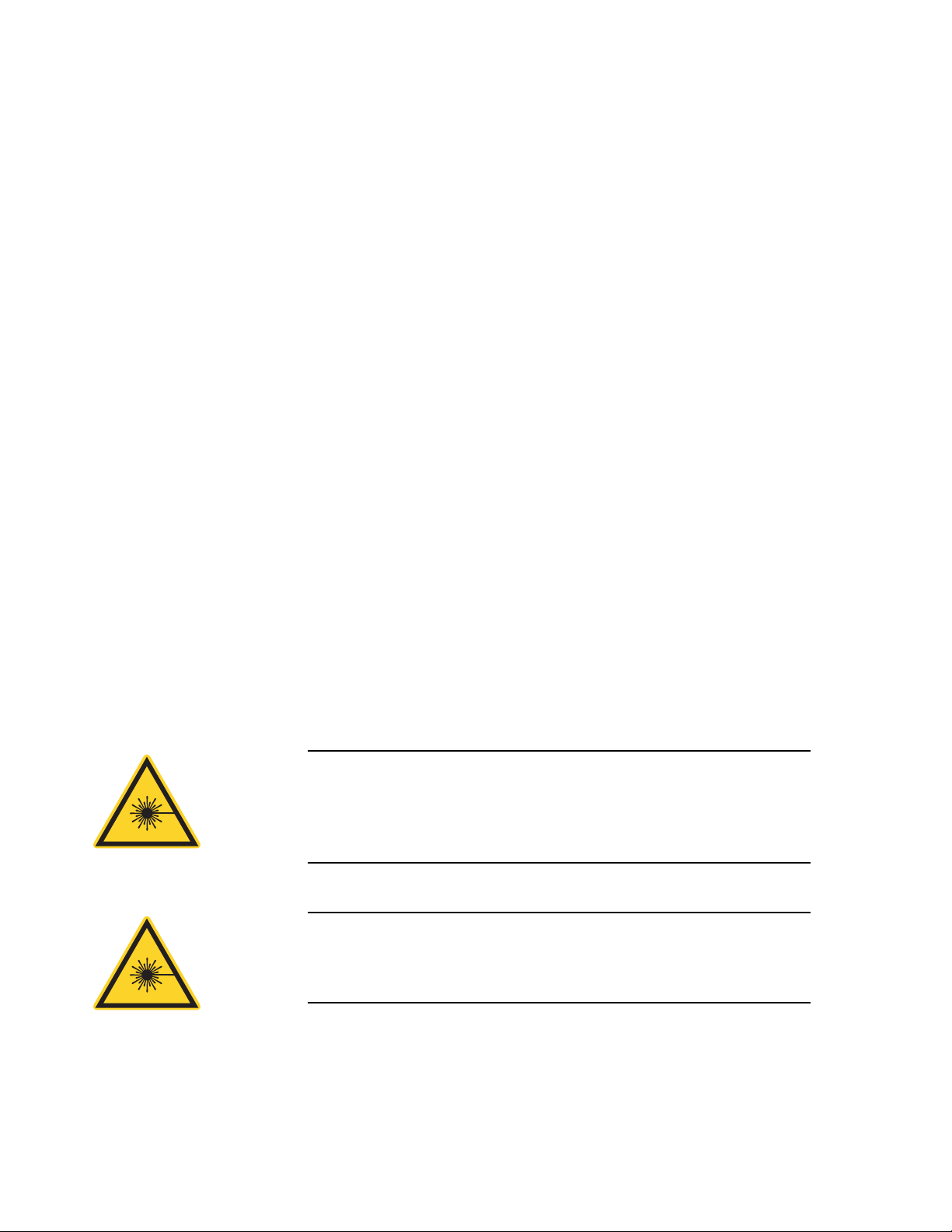
This symbol is intended to alert the operator to the danger of
exposure to hazardous visible and invisible laser radiation.
This symbol is intended to alert the operator to the presence of
dangerous voltages within the product enclosure that may be of
sufficient magnitude to constitute a risk of electric shock.
This symbol is intended to alert the operator to the danger of
Electro-Static Discharge (ESD) susceptibility.
This symbol is intended to alert the operator to the danger of
crushing injury.
This symbol is intended to alert the operator to the danger of a
lifting hazard.
viii
Page 11

Preface
Preface
RoHS Compliance
Export Control Laws Compliance
This manual has user information for the LabMax-Pro SSIM Laser
Power Meter.
This Coherent product is RoHS compliant.
It is the policy of Coherent to comply strictly with U.S. export
control laws.
Export and re-export of lasers manufactured by Coherent are subject
to U.S. Export Administration Regulations, which are administered
by the Commerce Department. In addition, shipments of certain
components are regulated by the State Department under the International Traffic in Arms Regulations.
The applicable restrictions vary depending on the specific product
involved and its destination. In some cases, U.S. law requires that
U.S. Government approval be obtained prior to resale, export or
re-export of certain articles. When there is uncertainty about the
obligations imposed by U.S. law, clarification must be obtained
from Coherent or an appropriate U.S. Government agency.
Publication Updates
Firmware Updates
Products manufactured in the European Union, Singapore,
Malaysia, Thailand: These commodities, technology , or software are
subject to local export regulations and local laws. Diversion contrary
to local law is prohibited. The use, sale, re-export, or re-transfer
directly or indirectly in any prohibited activities are strictly prohibited.
T o view information that has been added or changed since this publication went to print, connect to www.Coherent.com.
To get the latest version of LabMax firmware:
1. Download the LabMax-Pro SSIM Updater executable file
from our website and save it to your computer.
2. Attach the meter to the PC via USB.
3. Make sure the sensor is disconnected from the meter.
4. Turn the meter ON.
5. Double-click the LabMax-Pro SSIM Updater executable file
you downloaded and follow the instructions.
ix
Page 12

LabMax-Pro SSIM User Manual
x
Page 13
SECTION ONE: SAFETY
Carefully review the following safety information to prevent
personal injury and to prevent damage to this meter or any sensor
connected to the meter. This equipment has no user-serviceable
parts. For service information, refer to “Obtaining Service” (p. 6-3).
WARNING!
The use and measuring of lasers can be dangerous. This instrument operates on wavelengths that include non-visible laser
emissions.
Correct laser operating practice according to manufacturer recommendations is vital.
Safety
Eyewear and other personal protective equipment must be used
according to applicable laws and regulations.
If in doubt as to correct operating procedures, refer to the laser
manufacturer and your laser safety officer.
The equipment is not for use in critical medical environments.
WARNING!
Do not operate this instrument if its panels are removed or any
of the internal circuits are exposed.
WARNING!
Do not operate this instrument in wet or damp conditions, or in
an explosive atmosphere.
NOTICE!
Operate this instrument only within the specified voltage range.
1 - 1
Page 14
LabMax-Pro SSIM User Manual
NOTICE!
Do not operate this instrument if there are suspected failures.
Refer damaged equipment to qualified Coherent service
personnel.
Waste Electrical and Electronic Equipment (WEEE, 2002)
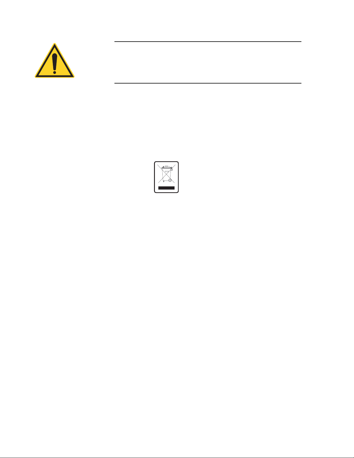
Figure 1-1. Waste Electrical and Electronic Equipment Label
Declaration of Conformity
The European Waste Electrical and Electronic Equipment (WEEE)
Directive (2002/96/EC) is represented by a crossed-out garbage
container label (see Figure 1-1). The purpose of this directive is to
minimize the disposal of WEEE as unsorted municipal waste and to
facilitate its separate collection.
Declaration of Conformity certificates are available upon request.
1 - 2
Page 15

Software Installation and Quick Start
SECTION TWO: SOFTWARE INSTALLATION AND
UICK START
Q
In this section:
• Software installation (this page)
• Initial setup instructions (this page)
• Taking a Standard-Speed measurement (p. 2-3)
• Taking a High-Speed measurement (p. 2-6)
• Taking a Snapshot measurement (p. 2-9)
• Taking a Pyroelectric energy measurement (p. 2-15)
• Setting up the Cursor feature (p. 2-18)
Software Installation
Initial Setup Instructions
To install the LabMax-Pro PC software and drivers:
1. Close all programs.
2. Insert the CD that shipped with the product into the CD-ROM
drive of your computer.
3. If Autorun is enabled on your system, installation will start automatically; otherwise, double-click the
file in the main folder on the CD.
4. Follow the on-screen instructions to complete the installation.
Complete the following instructions before using any of the Quick
Start tutorials presented in this section.
1. Install the
above).
2. Attach the PowerMax-Pro sensor to the LabMax-Pro meter by
connecting the DB-25 connector.
LabMax-Pro PC
software (see “Software Installation,”
LabMax-Pro_PC_Setup.exe
3. Attach the LabMax-Pro meter to the PC via a USB 2.0
High-Speed port.
4. Turn on the meter.
2 - 1
Page 16
LabMax-Pro SSIM User Manual
5. Start LabMax-Pro PC.
6. If a dialog screen similar to the one
7. [Main menu] Click Open Meter.
8. Select the COM port from the popup
9. View system information to confirm LabMax-Pro PC is
shown at right appears, click OK.
screen. Click the Select button to close
the dialog.
detecting the meter and the sensor.
WARNING!
Follow all laser safety procedures. The laser must be blocked or
switched OFF before starting any of the tutorials described in
this section.
WARNING!
Power to the LabMax-Pro meter must be OFF before starting
any of the tutorials described in this section.
2 - 2
Page 17
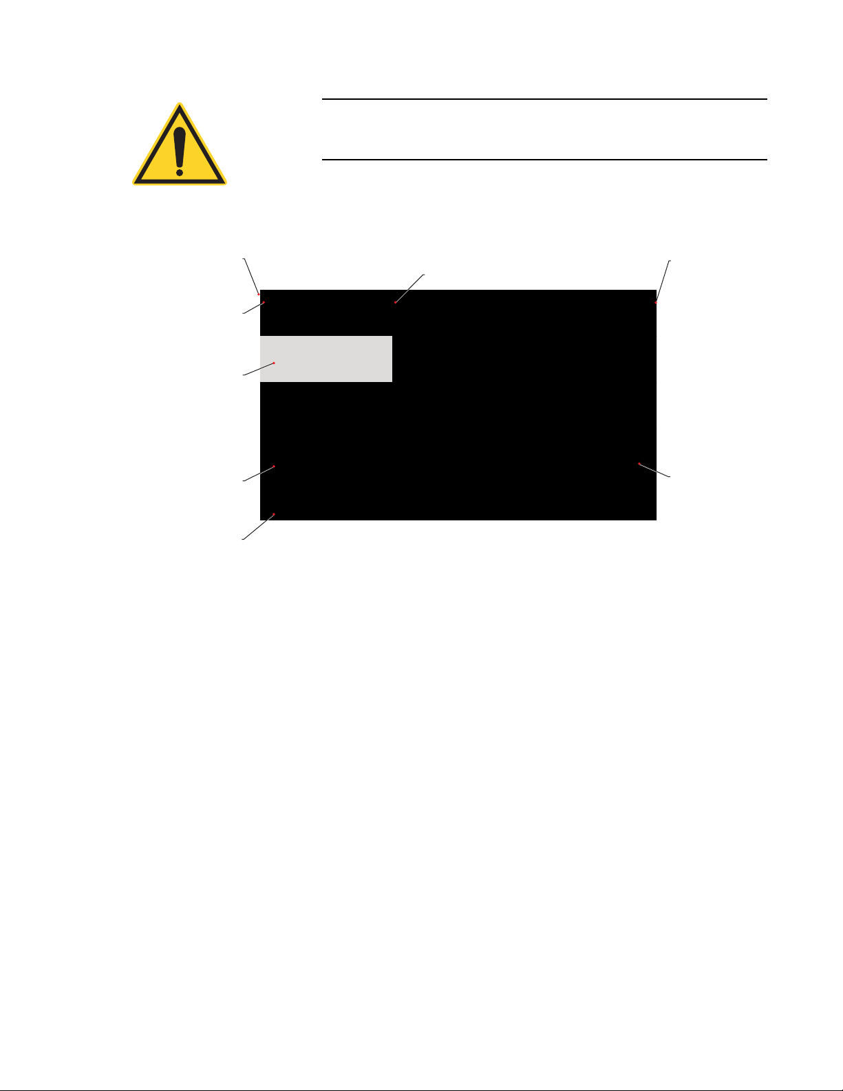
Software Installation and Quick Start
Main Menu
Measurements
Panel
Graphics
Panel
Statistics
Panel
Quick Access
Toolbar
Tabs
Information
and Help
Status
Bar
NOTICE!
Do not exceed the power or energy density limits of the sensor.
The following illustration shows the areas of the graphical user
interface you will need to access while using the tutorials presented
in this section.
Taking a Standard-Speed Measurement
This tutorial describes how to take a standard (10 Hz sampling rate)
power measurement.
Notes
• This mode is compatible with PowerMax-Pro, as well as ther-
mopile and optical power sensors.
• Using a PowerMax-Pro sensor in this mode provides nearly
instant average power readings. However, because data is
sampled every 100 milliseconds, temporal pulse information is
not displayed. Use High-Speed or Snapshot mode to view
temporal information.
• Standard-Speed mode can be used for measuring the average
power of CW or pulsed lasers. Use Standard-Speed mode
when measuring the average power of high repetition rate
short-pulsed lasers, such as picosecond, femtosecond, and
nanosecond lasers. In this 10 Hz sampling mode,
PowerMax-Pro provides extremely fast average power readings on these lasers. (Because Ultrafast and q-switched laser
2 - 3
Page 18

LabMax-Pro SSIM User Manual
Procedure
1. Complete the “Initial Setup Instructions” (p. 2-1).
2. [Home tab] Verify the High-Speed
3. Make sure either the laser is OFF or the beam is blocked.
4. [Home tab] Press the Zero button to zero the
pulses are too fast for PowerMax-Pro to resolve temporal pulse
information, and High-Speed and Snapshot mode sampling
rates will alias with the high kHz pulse repetition rates, it is
best to operate in Standard-Speed mode with these lasers.)
Mode checkbox is not checked.
sensor. A dialogue will display the zeroing
process, which will only take a second or two.
5. [Measurement tab] Select your laser
wavelength from the drop-down
menu. If your laser wavelength is not
available, choose the one closest to it
or, alternatively, click on [Edit Table]
in the menu and add your specific
wavelength to the Wavelength Table.
6. [Data Buffer tab] Enter a value in the
Capacity field that represents the
sample size you would like to collect.
This is also the sample size used to
calculate Statistics. Check the Continuous Mode checkbox if you want data
collection to continue until you stop it.
Uncheck the checkbox to have data collection end after the
Data buffer is full (which is when it reaches the value you
entered in the Capacity field).
7. [Data Buffer tab] Enter a value in the
Sample Count field. This value
represents how many samples are
displayed in the Trending chart at one
time.
2 - 4
Page 19

Software Installation and Quick Start
8. [Graphics panel] Click the Trending window.
9. Expose the sensor to the laser beam.
10. [Quick Access toolbar or Home tab]
Start data collection by pressing the
Start icon.
During data collection, the data is visible in the Trending chart,
statistics are updating in real time (based upon data entering the
buffer), and the Measurements panel displays a live reading. Here is
an example output screen:
— End of tutorial —
2 - 5
Page 20

LabMax-Pro SSIM User Manual
Taking a High-Speed Measurement
This tutorial describes how to take a high-speed (20 kHz sampling
rate) power measurement.
Notes
• High-Speed mode is only compatible with PowerMax-Pro
sensors.
• A data point is sampled every 50 microseconds, making this
mode very useful for real-time visualization of temporal shape
of modulated lasers with pulse lengths hundreds of microseconds or longer. This mode also provides fast feedback about
changes in power output from CW sources.
• High-Speed mode is also used to set up Snapshot
mode—primarily by confirming the meter is accurately triggering on the laser pulses before moving into Snapshot mode.
Refer to “Taking a Snapshot Measurement” (p. 2-9).
• To avoid aliasing effects between the meter sampling rate and
the laser pulses, this mode cannot be used with lasers modulated at over 2.5 kHz pulse repetition frequency.
Procedure
1. Complete the “Initial Setup Instructions” (p. 2-1).
2. [Home tab] Verify the High-Speed
Mode checkbox is checked.
3. Make sure either the laser is OFF or the beam is blocked.
4. [Home tab] Press the Zero button to zero the
sensor. A dialogue will display the zeroing
process, which will only take a second or two.
5. [Home tab] Click the Range
drop-down menu and select one of the
three ranges that are available: AUTO
(for auto-range), and two fixed ranges
signified by power limits (High and
Low).
2 - 6
Page 21

Software Installation and Quick Start
6. [Measurement tab] Select your laser
wavelength from the drop-down
menu. If your laser wavelength is not
available, choose the one closest to it
or, alternatively, click on [Edit Table]
in the menu and add your specific
wavelength to the Wavelength Table.
7. [Data Buffer tab] Verify that the
Enable Snapshot Mode checkbox is
not checked.
8. [Data Buffer tab] Enter a value in the
Capacity field that represents the
sample size you would like to collect.
This is also the sample size used to
calculate Statistics. Check the Continuous Mode checkbox if you want data
collection to continue until you stop it.
Uncheck the checkbox to have data collection end after the
Data buffer is full (which is when it reaches the value you
entered in the Capacity field).
T ip: If the application displays a “Missing” warning, it means data
was lost while transferring the data in real time from the meter's
buffer to the PC. This usually occurs because the computer is not
able to keep up with the high rate of data continuously streaming
from the meter. If this warning occurs, ensure the USB connection is
a USB 2.0 High-Speed port and close other open applications.
Another option is to reduce the Capacity buffer size. You can also
export the data file to examine the error indicators to determine
where and how much data was lost.
9. [Data Buffer tab] Enter a value in the
Sample Count field. This value
represents the number of samples you
want displayed in the Trending
window at one time.
2 - 7
Page 22

LabMax-Pro SSIM User Manual
10. [Graphics panel] Click the Trending window.
11. Expose the sensor to the laser beam.
12. [Quick Access toolbar or Home tab]
Start data collection by pressing the
Start icon. Note the loading indicator
()
turns green while the data is loading.
During data collection, the data is visible in the Trending chart,
statistics are updating in real time (based upon data entering the
buffer), and the Measurements panel displays a live reading. Here is
an example output screen:
— End of tutorial —
2 - 8
Page 23

Software Installation and Quick Start
Taking a Snapshot Measurement
This tutorial describes how to take a Snapshot (625 kHz sampling
rate) power measurement.
Notes
• Snapshot mode is only compatible with PowerMax-Pro
sensors.
• This is a special acquisition mode that captures high-speed
data at 625 kHz or at 1.6 microseconds per sample (capture
rate to the internal buffer inside the meter). Due to the h igh rate
of data acquisition in this mode, it is necessary to temporarily
store the data in the instrument’s hardware buffer, as it is not
possible to upload it in real-time via USB. Once the data acquisition is complete, the instrument uploads the data to the PC,
where it is placed in the Capture buffer and displayed in the
software.
• To avoid aliasing effects between the meter sampling rate and
the laser pulses, do not use this mode with lasers modulated at
over 80 kHz pulse repetition frequency.
Process
During Snapshot mode, the hardware waits for a trigger event before
acquiring data. The process works like this:
1. You define the data acquisition settings (including trigger
settings), enable Snapshot mode, and press Start.
2. The meter searches for a trigger and the user interface waits for
the meter to start sending data.
3. When a trigger is found, the meter starts filling its own Capture
buffer.
4. When the buffer is full, the data is sent to the user interface,
which displays it.
Procedure
The first part of the procedure is to define the data acquisition
settings, including trigger settings. This is done in High-Speed
mode.
1. Complete the “Initial Setup Instructions” (p. 2-1).
2. [Home tab] Verify the High-Speed
Mode checkbox is checked.
3. Make sure either the laser is OFF or the beam is blocked.
2 - 9
Page 24

LabMax-Pro SSIM User Manual
4. [Home tab] Press the Zero button to zero the
5. [Home tab] Click the Range
6. [Measurement tab] Select your laser
sensor. A dialogue will display the zeroing
process, which will only take a second or two.
drop-down menu and select one of the
two fixed ranges (which signify the
maximum power limits for each
range).
Note: Snapshot does not support Auto
ranging.
wavelength from the drop-down
menu. If your laser wavelength is not
available, choose the one closest to it
or, alternatively, click on [Edit Table]
in the menu and add your specific
wavelength to the Wavelength Table.
7. [Data Buffer tab] Verify that the
Enable Snapshot Mode checkbox is
not checked.
8. [Data Buffer tab] Verify that the
Continuous Mode checkbox is not
checked, and then enter a value in the
Capacity field (20,000 represents one
second of data collection, which
should be adequate to set up Snapshot
mode). The purpose of this step is to
confirm good data collection and proper pulse triggering.
9. [Data Buffer tab] Enter a Sample
Count of 1500 and an Update Period
of 0.5. These are good values with
which to start.
2 - 10
Page 25

Software Installation and Quick Start
10. [Trigger tab] Enter a
Level setting in Watts
that represents a level
approximately 50%
between zero and the peak power you expect each pulse to
have. If you do not know peak power, enter a Level setting
between zero and the average power. Verify that Source is set
to Internal, Edge is set to Positive, and Delay is set to 0 (zero).
11. [Trending window] Make sure the Show Trigger Markers
checkbox is checked (Settings drop-down menu, under the
Views tab). This allows you to confirm the meter is auto triggering on the pulses, which is required before entering Snapshot mode.
12. Expose the sensor to the laser beam.
13. [Quick Access toolbar or Home tab]
Start data collection by pressing the
Start icon.
14. [T rending window] After data collection is complete, confirm
that each pulse has a trigger marker, represented by a red
vertical line plotted at each trigger event. The green line
represents the trigger threshold level. If the red trigger ma rkers
are not visible, or are not consistently triggering on each pulse
event, go back and adjust the Trigger Level setting in the
2 - 11
Page 26

LabMax-Pro SSIM User Manual
Now that trigger events are occurring and pulses are properly
displaying, it’s time to move into Snapshot mode.
The laser does not need to be firing onto the sensor during the
next several steps of this tutorial. You will be asked to fire the
laser again in step 20.
Trigger tab. Keep repeating this process until trigger events are
occurring as expected.
15. [Data Buffer tab] Check the Enable
Snapshot Mode checkbox.
16. When Snapshot mode is activated, a warning dialog such as
the one shown below will appear if particular settings (such as
Range and Data Buffer) are not set up correctly. If this
happens, click the Confirm Changes button and the application
will automatically adjust those settings for you.
17. [Data Buffer tab] Click the Change
Settings button.
2 - 12
Page 27

Software Installation and Quick Start
18. [Data Buffer tab] Adjust the capacity up or down by typing in
a new value or using the slider . How long a Snapshot you want
to use depends on the laser pulse length and how many pulses
you want to capture.
In this example, the default setting is the maximum capacity of
240,000 samples, which is collected in 384 milliseconds. If
you want to capture the portion of the first pulse before the
trigger event, add in some pre-trigger samples. (If this is 0
(zero), Snapshot will begin at the time of the trigger event,
which occurs after the first pulse begins.) Click the Save
button to close the dialog.
Tip: Reducing the number of samples allows pulses to be
viewed with higher resolution in the trend chart. If you do not
see as high a resolution as desired, try setting the capacity
duration much lower, such as ten times the pulse repetition
period.
19. [
Quick Access toolbar
or
Home tab
]
Start data collection by pressing the
Start icon. A Snapshot Mode icon
()
will appear in the Status bar at the
bottom of the application and display a
red oscillating bar until the laser fires
and a trigger event is detected.
20. Fire the laser . If no trigger event is detected, the Snapshot icon
will remain in the red waiting mode. If this happens, there are
two options: 1) Press the Force Trigger button (to the right of
the red oscillating bar). This will force the meter into
collecting Snapshot data, regardless of whether or not it finds
a trigger. 2) Press Stop and readjust the trigger settings in
High-Speed mode. If a trigger event is detected, the Snapshot
Mode icon ( ) will turn green
and actively display the progress of loading the data from the
internal Snapshot buffer in the meter to the PC application.
This can take several seconds, depending upon the size of the
Snapshot Capacity setting.
2 - 13
Page 28

LabMax-Pro SSIM User Manual
After the Snapshot data is loaded, the result is plotted in the
Trending window . Zoom in to observe detailed temporal pulse infor mation, as shown in the examples below.
There are three ways to zoom a view:
1. Drag the mouse to define a portion of the display.
2. Use the mouse wheel to zoom in or out.
3. Use the scroll bar to define a portion of the display (by dragging either the left or right handle of the scroll bar) or scroll the
display (by dragging the scroll bar to the left or right).
2 - 14
Page 29

Software Installation and Quick Start
Taking a Pyroelectric Energy Measurement
— End of tutorial —
This tutorial describes how to take an energy reading with a pyroelectric sensor.
Procedure
1. Complete the “Initial Setup Instructions” (p. 2-1).
2. [Home tab] Select Energy Joules
Mode and the energy range (typically
the next higher range than the
expected energy level being
measured).
2 - 15
Page 30

LabMax-Pro SSIM User Manual
3. Make sure either the laser is OFF or the beam is blocked.
4. [Measurement tab] Select your laser
5. [Data Buffer tab] Enter a value in the
wavelength from the drop-down
menu. If your laser wavelength is not
available, choose the one closest to it
or, alternatively, click on [Edit Table]
in the menu and add your specific
wavelength to the Wavelength Table.
Capacity field that represents the
sample size you would like to collect.
This is also the sample size used to
calculate Statistics. Check the Continuous Mode checkbox if you want data
collection to continue until you stop it.
Uncheck the checkbox to have data collection end after the
Data buffer is full (which is when it reaches the value you
entered in the Capacity field).
T ip: If the application displays a “Missing” warning, it means data
was lost while transferring the data in real time from the meter's
buffer to the PC. This usually occurs because the computer is not
able to keep up with the high rate of data continuously streaming
from the meter. If this warning occurs, ensure the USB connection is
a USB 2.0 High-Speed port and close other open applications.
Another option is to reduce the Capacity buffer size. You can also
export the data file to examine the error indicators to determine
where and how much data was lost.
6. [Data Buffer tab] Enter a value in the
Sample Count field. This value
represents the number of samples you
want displayed at one time in the
Trending window.
7. [Trigger tab] Set an
appropriate Trigger
Level (based on either
units of joules or
percent) and also set the Source to Internal.
Tip: If the energy level being measured is known, you can enter the
trigger level as a joules value that is lower than the expected energy
level to be measured. You can also set the trigger level as a percent
of the currently-selected energy range. The trigger level is a
threshold used to determine which signals will be collected as
energy measurements and which signals will be ignored as noise.
2 - 16
Page 31

Software Installation and Quick Start
Setting the trigger level too high can result in actual energy pulses
being missed. Setting the trigger level too low can result in noise
being picked up as readings. Set the trigger level at a threshold
below the energy being measured and above the noise level of the
sensor. To view the acceptable limits for the trigger level settings,
hover the cursor over these settings in the software.
8. [Graphics panel] Click the Trending window.
9. Expose the sensor to the laser beam.
10. [Quick Access toolbar or Home tab]
Start data collection by pressing the
Start icon.
During data collection, the data is visible in the Trending chart,
statistics are updating in real time (based upon data entering the
buffer), and the Measurements panel displays a live reading. Here is
an example output screen:
2 - 17
Page 32

LabMax-Pro SSIM User Manual
Tip: Monitor both the energy level being measured and the rep rate
calculation to determine if the meter is triggering appropriately. If
those readings do not match the readings expected from the laser,
readjust the trigger level setting until the energy level and the rep
rate fall within an acceptable range.
— End of tutorial —
Setting up the Cursor Feature
This tutorial describes how to set up the Cursor feature within the
LabMax-Pro PC software.
The Cursor feature is a powerful tool for analyzing pulses that have
been captured in the LabMax-Pro software. You can use it either
after stopping live data collection or after importing a saved data file
into the software.
Procedure
1. [Graphics panel] Click the “Settings” drop-down menu in the
Trending window.
2. Check “Show Selection Bounds Cursors” checkbox on the
drop-down menu.
2 - 18
Page 33

Software Installation and Quick Start
Cursors can be dragged within the trend screen to fit around certain
pulse shapes or features.
Based on the region of the plot selected by
the cursors, the “Selection Bounds” statistics automatically update.You can use the
“Time Axis - W idth” measurement to determine pulse width, rise-time, or fall-time of
a pulse in the plot. The software also shades
the area under the curve within the cursors
and calculates the energy of a pulse or
pulses within that region.
The Energy Baseline setting can be used to determine if the pulse
energy calculation is based on the 0 mW baseline level or the lower
cursor level.
2 - 19
Page 34

LabMax-Pro SSIM User Manual
The “Snap To Triggers” setting can be used to set the cursors to the
trigger point at the beginning of successive pulses. Then the “Time
Axis - Width” measurement can be used to determine the period
between pulses.
To reset the cursors to their original positions, make sure “Snap To
Triggers” is not checked, then uncheck and recheck the “Show
Selection Bounds Cursors” checkbox. This will reset the cursors in
the Trend display.
2 - 20
— End of tutorial —
Page 35

SECTION THREE: DESCRIPTION
In this section:
• Introduction (this page)
• Operating mode overview (page 3-2)
• Product features (page 3-4)
• LabMax-Pro PC software features (page 3-5)
• Thermopile and PowerMax-Pro Sensor technology (page 3-6)
• Applying wavelength compensation accuracy (page 3-8)
Description
Introduction
The LabMax-Pro represents the next generation of Coherent's
groundbreaking LabMax line. This power meter combines the
power and versatility of the LabMax, with two new high-speed
sampling modes when used with PowerMax-Pro technology (patent
pending). Coherent has developed the LabMax-Pro SSIM laser
power meter to fully capitalize on the capabilities of PowerMax-Pro
sensors. The meter is also compatible with PM model thermopiles in
the standard operating mode.
LabMax-Pro SSIM is packaged as a Smart Sensor Interface Module
(SSIM) that interfaces with a host computer through either USB or
RS-232. LabMax-Pro PC, a new Windows PC application, then
enables instrument control and displays measurement
results—including laser tuning, high-fidelity pulse shape visualization and energy integration—on a host computer. The software
provides a wide range of analytical functions, including live statistics, histograms, trending and data logging. The user interface
permits flexible sizing of informational panes within the application,
in which contents are auto-sized dynamically as the panes are
adjusted, letting the user size the information of greatest importance.
Also, a complete set of host commands can be sent through either the
USB or RS-232 interface, which is useful for embedded applications.
Besides PC interfacing, LabMax-Pro SSIM also includes an analog
output with user-selectable voltages of 0 to 1V, 2V, or 4V. Triggering
is done with either an external trigger input or a user-adjustable
internal trigger.
3 - 1
Page 36

LabMax-Pro SSIM User Manual
Operating Mode Overview
Standard-Speed Mode
High-Speed Mode
LabMax-Pro SSIM uses three operating modes:
• Standard-Speed
• High-Speed
• Snapshot
These are discussed, next.
The Standard-Speed operating mode of the LabMax-Pro SSIM uses
a typical 10 Hz sampling rate. At this data rate, PowerMax-Pro
sensors supply an almost instantaneous power reading, similar to a
photodiode, while also taking advantage of the sensor's ability to
directly read very high powers. The standard operating mode is best
used to measure the power of CW lasers or the average power of
high-repetition rate lasers.
High-speed mode operates at a continuous data sampling rate of
20 kHz, permitting pulse shape analysis of modulated lasers with
repetition rates up to 2.5 kHz. These types of pulse trains are
common in many laser-based medical treatments and some material
processing applications, such as micro welding.
Figure 3-1, below, shows data collected using a 20W CO2 laser to
show the type of detail you can get in this mode.
Figure 3-1. Example of Detail Available When Using High-Speed Mode
3 - 2
Page 37

Description
Snapshot Mode
A faster high-speed sampling mode—“Snapshot Mode”—provides
burst sampling at a rate of 625 kHz for a maximum of 384 milliseconds. This mode lets you see the temporal characteristics of modulated pulses used in commercial cutting, engraving and drilling
applications, as well as long pulses and pulse trains used in aesthetic
medical applications. This temporal detail shows the true performance of the laser—previously masked by slow thermopiles—thereby providing more information to assist setting up
process recipes and for monitoring system performance in manufacturing.
Figure 3-2, below, shows the data quality and high pulse shape
fidelity that is achievable.
Modulated 10.6 µm CO2 Laser
50 µs PW
8 kHz PRF
40% Duty Cycle
Figure 3-2. Example of Detail Available When Using Snapshot Mode
3 - 3
Page 38

LabMax-Pro SSIM User Manual
Product Features
• USB 2.0 “High-Speed” and RS-232 connectivity.
• Instrumentation platform is compatible with PM model ther-
mopile sensors, PowerMax-Pro sensors, LM model position-sensing thermopiles, LM-2 & OP-2 optical sensors, and
EnergyMax DB-25 pyroelectric energy sensors.
• High-speed sampling up to 625 kHz for laser temporal pulse
analysis when used with PowerMax-Pro sensors.
• Operation up to 10 kHz each pulse with pyroelectric sensors.
• Windows PC application included. Updates are available from
within the application or from the Coherent website.
• 32-bit and 64-bit Microsoft™ Windows™ 7 and W indows™ 8
compatibility.
• Direct host command support for OEM integration.
• The meter's internal firmware is field upgradeable, so you can
have access to the latest LabMax features.
• High resolution and fast analog-to-digital converter supports
up to five digits of resolution and measurement accuracy
equivalent to that found in Coherent's other LabMax meters.
• Meter supports spectral compensation for accurate use at
wavelengths that are different from the calibration wavelength.
Each sensor receives a different spectral compensation curve
specific to the responsivity of its specific element, as well as
transmission characterization of any associated optics.
• Long-pulse joules capability with thermopile sensors in Stan-
dard operating mode
• Trending mode includes adjustable x-y cursors and energy
integration of captured pulses using PowerMax-Pro sensors.
3 - 4
Page 39

LabMax-Pro PC Software Features
Description
Plug-and-play application software is supplied and includes the
following features:
• Trending Feature
• Trend average power stability over time.
• Visualize and track pulse shape and peak power. High
fidelity resolution of temporal pulses greater than 10
microseconds.
• Beam position target and trend chart when used with posi-
tion-sensing LM model thermopiles.
• Statistics (mean, minimum, maximum, stability and standard
deviation)
• Export comma or tab-delimited data for analysis in a spread-
sheet—for example, Microsoft™ Excel™—or import directly
back into LabMax PC application.
• Tuning (needle dial or bar graph)
• Histogram
• Run multiple instances of software to operate multiple sensors
at the same time.
3 - 5
Page 40

LabMax-Pro SSIM User Manual
For system integrators and for implementations that include
customer-written software, the sensors have a comprehensive
command set that is easy to access:
• USB driver is a Virtual COM port and supports simple ASCII
• Using customer-written software, the remote interfacing host
• National Instruments™ LabVIEW™ examples for easy
Thermopile and PowerMax-Pro Sensor Technology
host commands for remote interfacing.
command set permits sensors to be remotely controlled.
LabVIEW integration.
Thermopile Sensors
For many years thermopiles have been the detector of choice for
high power lasers. These detectors operate on the thermoelectric
principle in which thermal energy is converted into electrical energy.
The typical thermopile has a central, light absorbing disk, a series of
thermocouples that surround the disk, and an annular heatsink
around the ring of thermocouples—refer to the following figure.
Figure 3-3. Construction of a Traditional Radial Thermopile
In operation, incident laser energy falls on the absorbing disk in the
center of the detector and is converted into heat. This disk is typically coated with a material that absorbs light over a very broad
3 - 6
Page 41

Description
wavelength range to increase sensitivity. The heat then flows across
the width of the thermopile disk to the heatsink, which is held at a
near constant ambient temperature by either air or water cooling.
The temperature difference between the absorber and heatsink is
converted into an electrical signal by the thermocouples. Calibrated
electronics in the meter convert this electrical signal into a laser
power reading.
Thermopile sensors have several advantages, including a very broad
spectral range, an ability to work over a wide range of input powers,
high laser damage resistance and uniform spatial response (meaning
insensitivity to changes in beam size, position or uniformity). The
limitation of the technology is that the transfer of heat across the
width of the thermopile disk makes this technology inherently slow .
Specifically , it frequently takes several seconds before the heat flow
caused by the laser reaches equilibrium and the power measurement
becomes stable on the display. Physically larger sensors take longer
to reach this stable state. This slow response time makes thermopiles
best suited for measuring CW laser power . For pulsed lasers, the best
they can deliver is average power over a finite time interval, or total
integrated energy from a long burst of pulses.
PowerMax-Pro Sensors
Coherent developed PowerMax-Pro technology to meet the growing
need for a laser power sensor that offers the broad wavelength sensitivity , lar ge dynamic range and high damage resistance of a thermo-
pile, with the fast response speed approaching that of a semiconductor photodiode. The PowerMax-Pro is constructed and configured differently than a thermopile. Specifically, in this device the
heat flows vertically through the detector and the electrical field that
is generated moves perpendicular to the heat flow—refer to
Figure 3-4, below.
Figure 3-4. Basic Configuration of a PowerMax-Pro Sensor
3 - 7
Page 42

LabMax-Pro SSIM User Manual
The materials used in this sensor are a stack of films which have
layer thicknesses on the order of microns. Incident laser light is
absorbed and generates heat which can flow very quickly through
these thin layers to the heatsink below the detector, where it is dissipated. The electrical signal from the thin film layers moves laterally
to the edges of the device where it is measured by tapping into the
sensor electrodes.
Compared with the traditional radial-flow thermopile—which has a
sensing time constant value of several seconds—the time constant
for the thin film configuration is in the microsecond range. This
enables the sensor to supply an essentially instant power measurement without any overshoot—refer to Figure 3-5, below. The
PowerMax-Pro sensor preserves the main benefits of the traditional
thermopile architecture, namely large active area (30 mm x 30 mm),
wide dynamic range (50 mW to 150W), high damage resistance
(14 kW/cm²) and broad wavelength range (300 nm to 11 µm).
Figure 3-5. The Rise Time of a Typical Mid-power Thermopile (30W) Compared with the
PowerMax-Pro
The response speed of PowerMax-Pro sensors lets users move
beyond just measuring average power and enables visualization of
the temporal pulse shape and peak power of modulated lasers with
pulse lengths greater than 10 µs. These pulses can be integrated to
calculate individual pulse energy.
Applying
Wavelength
Overall measurement accuracy is a combination of the meter and
sensor calibration uncertainties. For an up-to-date list of all compatible sensors and their specifications, go to www.Coherent.com/LMC.
Compensation
Accuracy
3 - 8
Page 43

Description
U2 = + W
2
Measurement Accuracy =
where:
U
= Percent Calibration Uncertainty
W = Wavelength Accuracy
Wavelength Compensation Accuracy
The combined accuracy is based upon practices outlined in the
National Institute of Standards Guidelines for Evaluating and
Expressing Uncertainty (NIST Technical Note 1297, 1994 Edition).
The combined accuracy of the measurement is calculated by using
the law of propagation of uncertainty using the
“root-sum-of-square” (square root of the sum of squares), sometimes described as “summing in quadrature” where:
Coherent uses several coatings to capture the incident radiation on
thermal sensors. The specifications list which coating is for each
sensor. Typical wavelength ranges and response curves for these
coatings are shown below. Each sensor has a spectral curve generated from reflectance measurements taken with spectrometers or
direct laser lines. The reflectance data are converted into a wavelength compensation look-up table that is loaded into the sensor.
This data is accessed by selecting a wavelength of operation in the
software.
Figure 3-6. RV Spectral Correction for Thermal Sensors (Normalized to Calibration
Wavelength)
3 - 9
Page 44

LabMax-Pro SSIM User Manual
Figure 3-7. RV Spectral Correction for PowerMax-Pro Sensors (Normalized to Calibration
Wavelength)
Table 3-1. Wavelength Compensation Accuracy
Sensor
All PM model thermopiles ± 1.5% 10600
PowerMax-Pro HD Coating ± 3% 810
PowerMax-Pro BB Coating ± 2% 810
a. Refers to wavelengths different from the calibration wavelength.
Wavelength Compensation
Accuracy
Wavelength (nm)
a
Calibration
3 - 10
Page 45
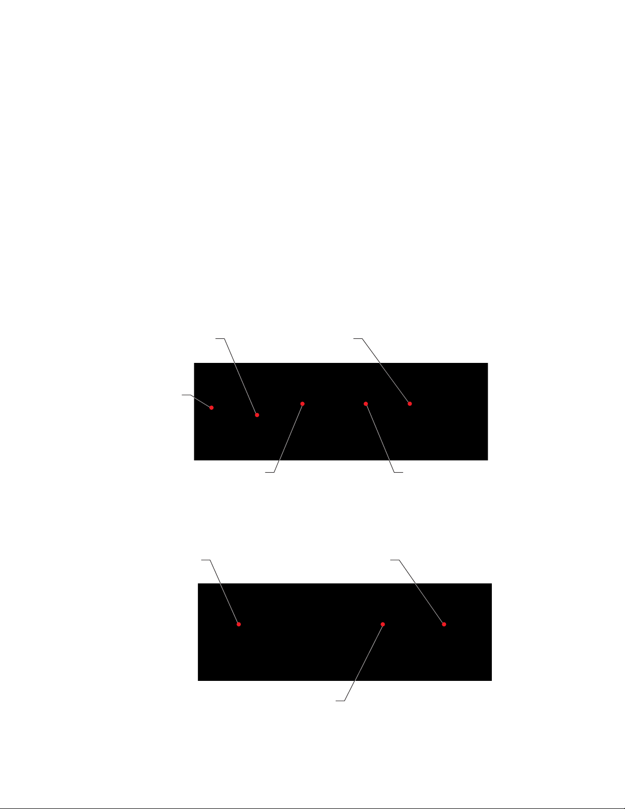
Hardware
Power
Trigger Output
Port
Analog Output
Port
DB-25
Port
External Trigger
Input Connector (Type SMB)
Power
Jack
Operation
SECTION FOUR: OPERATION
In this section:
• Hardware (this page)
• Sensor compatibility (p. 4-2)
• USB/RS-232 (p. 4-2)
• Power supply (p. 4-2)
• External trigger input (p. 4-2)
• External trigger output (p. 4-4)
• Analog output (p. 4-4)
• PC application (p. 4-5)
USB
Switch
Connector (Type SMB)
RS-232
Connector (Type SMB)
Figure 4-1. Meter Front Panel
Figure 4-2. Meter Back Panel
4 - 1
Page 46

LabMax-Pro SSIM User Manual
Sensor Compatibility
USB/RS-232
Power Supply
External Trigger Input
PowerMax-Pro, PM model thermopiles, LM model thermopiles,
OP-2 & LM-2 optical sensors, and DB-25 EnergyMax sensors.
LabMax-Pro requires a USB 2.0 High-Speed USB to communicate
with the PC. (RS-232 connections are intended for OEM integration
and will cause reduced data transfer rates.)
Power is supplied through an external 12 VDC/15W power supply
(included).
To prevent ground loop noise from interfering with accurate
measurement, the external SMB trigger input is optically isolated
from the LabMax-Pro internal ground by an optoisolator. The
following figure shows a simplified schematic of the external trigger
input circuitry.
Figure 4-3. External Trigger Input Circuitry
4 - 2
Page 47
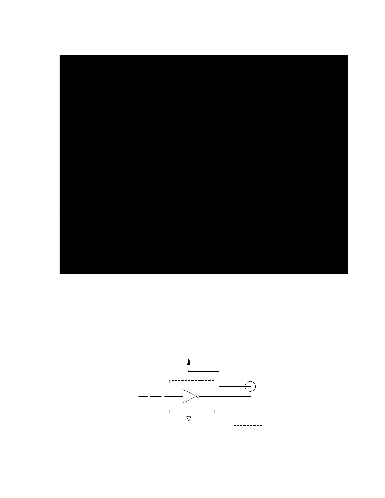
Figure 4-4 shows examples of trigger outputs.
Yellow = external trigger input
Blue = optocoupler to output logic
+ 5V
BNC
Buffer
Circuit
Operation
Figure 4-4. Example Trigger Output Screens
Trigger input pulse must be 3 to 6V, 500 nS pulse from a 50 ohm
source. If a current source is used, the minimum trigger current is
5 mA. One possible buffer circuit is shown in Figure 4-5.
LabMax
Instrument
Trigger
Signal
Common
Trigger In
Figure 4-5. Boosting Source Current of Triggering Device
4 - 3
Page 48

LabMax-Pro SSIM User Manual
The external trigger signal can be either a rising or a falling edge.
Trigger polarity is selected in the SETUP: Trigger menu.
NOTICE!
T rigger signals gr eater than 7 VDC can damage the optoisolator
and should be avoided.
External Trigger Output
The Trigger Out SMB connector is a 15 nS, 5V pulse from a 50 ohm
source. It is designed to cascade into another device’s trigger input.
Figure 4-6. External Trigger Output Circuitry
Analog Output
When power is on, the Analog Out SMB connector outputs a voltage
in proportion to the current laser measurement. The output voltage
is zero (0) volts when the measured energy or power is zero (0) or
less. The output voltage is the full-scale output voltage when the
measured energy or power is full-scale or over-ranged. The
full-scale output voltage (1, 2, or 4V from a 50 ohm source) is
selected via the meter or the host interface. Factory default full-scale
output voltage is 2V.
4 - 4
Page 49

Operation
Help
Button
PC Application
Figure 4-7. Location of PC Application Help Button
For detailed information about LabMax-Pro PC, open the software
and launch the Help file by clicking the Help button at the top right
of the screen.
4 - 5
Page 50

LabMax-Pro SSIM User Manual
4 - 6
Page 51

SECTION FIVE: HOST INTERFACE
Special Considerations
Host Interface
In this section:
• Special considerations (this page)
• Host Command quick reference (p. 5-3)
• Commands and queries (p. 5-6)
• Persistent parameters (p. 5-28)
• Host Interface glossary (p. 5-28)
Message Terminators
Messages Received by the Meter
Messages Sent by the Meter
Messages between the meter and the host computer are comprised
entirely of ASCII string characters. All ASCII message strings
passing through the host interface are terminated to signal the end of
a message string.
Messages received by the sensor must be terminated by a carriage
return (decimal 13). Line feed characters (decimal 10) are discarded
so message terminator flexibility can be attained. A command or
query is considered incomplete without the terminator. The
maximum length of any message received by the meter is limited to
200 bytes.
All messages sent by the meter are terminated by a carriage return
(decimal 13) and line feed (decimal 10) pair.
5 - 1
Page 52

LabMax-Pro SSIM User Manual
Using the RS-232 Interface
Data Flow Control No software or hardware flow control methods for serial communi-
cation is used.
Baud Rate and Other Communication Settings
Using the USB Interface
Syntax and Notation Conventions
The host must use a fixed baud rate setting of 115200, 8-bit,
1-stop bit, no-parity. Refer to the following table:
Table 5-1. RS-232 Communication Settings
Baud 115200
Parity None
Data bits 8
Stop bits 1
Flow control None
When the meter is connected to a host via USB, it is viewed as a
virtual serial communications port.
Syntax and notation conventions specified by the SCPI Standard are
followed for all SCPI commands and queries unless otherwise specified. Refer to the SCPI Standard for more information.
The base-10 numeric data format specification is used heavily in this
section. Unless otherwise specified, numeric data items are represented as:
• Integer values
• Non-scientific notation floating point values
• Scientific notation floating point values (uppercase or lower-
case E)
For example, the following data values are functionally equivalent:
• 31256
• 31256.0
• 3.1256e4
• 31.256e3
• +3.1256e+4
Unless otherwise specified, non-numeric data items (typically
referred to as strings) are not quoted.
5 - 2
Page 53

Host Interface
Host Command
Quick
The following table gives a brief description of all LabMax-Pro host
commands. For detailed information about a specific command, go
to the page referenced in the right-hand column.
Reference
Table 5-2. Host Command Quick Reference (Sheet 1 of 3)
Command Description Page #
SCPI Common Commands
*RST
*IDN? Gets the meter identification string. 5-6
SYSTem:TYPE? Returns the system type string. 5-7
SYSTem:STATus? Gets the system status code. 5-7
SYSTem:FAULt? Gets the system fault code. 5-8
SYSTem:RESTore Restores all user settings to the factory state. 5-8
SYSTem:SYNC Resets the system measurement sync timer. 5-8
SYSTem:SYNC? Gets the system measurement sync timer. 5-8
SYSTem:COMMunicate:HANDshaking
SYSTem:COMMunicate:HANDshaking? Sets the state of SCPI message round trip handshaking. 5-9
Resets all operational parameters to their power-on
states.
System Options
Communications
Selects the state of SCPI message round trip handshaking.
5-6
5-9
Error Record Reporting and Collection
SYSTem:ERRor:COUNt?
SYSTem:ERRor:NEXT? Gets the next error record(s) in the error queue. 5-11
SYSTem:ERRor:ALL?
SYSTem:ERRor:CLEar Clears all error records in the error queue. 5-11
Gets the number of error records in the error queue at
the time of the query.
Gets all error records in the error queue at the time of
the query.
5-11
5-11
Measurement Setup and Control
CONFigure:MEASure:MODe
CONFigure:MEASure:MODe? Gets the measurement mode of the instrument. 5-12
CONFigure:MEASure:SNAPshot:SELect
CONFigure:MEASure:SNAPshot:SEL?
CONFigure:MEASure:SNAPshot:PREbuffer Sets the pre-trigger buffer size in samples. 5-12
CONFigure:MEASure:SNAPshot:PREbuffer? Gets the pre-trigger buffer size in samples. 5-12
CONFigure:MEASure:SOURce:SELect
CONFigure:MEASure:SOURce:SEL? Gets the current data channel. 5-13
CONFigure:MEASure:SOURce:LIST?
Sets the instrument to a measurement mode of dBm,
Watts or Joules.
Sets the instrument to acquire data in a burst or snapshot fashion.
Gets status of instrument to acquire data in a burst or
snapshot fashion.
Sets the instrument to acquire data from either the slow
or fast channel.
Returns a list of available source channel selections for
the attached probe.
5-12
5-12
5-12
5-13
5-13
5 - 3
Page 54

LabMax-Pro SSIM User Manual
Table 5-2. Host Command Quick Reference (Sheet 2 of 3)
Command Description Page #
CONFigure:SPEedup Sets the speedup state. 5-13
CONFigure:SPEedup? Gets the speedup state. 5-13
CONFigure:AREA:CORRection Enables/disables area correction. 5-13
CONFigure:AREA:CORRection? Gets the area correction state. 5-13
CONFigure:AREA:APERture Sets the aperture area. 5-13
CONFigure:AREA:APERture? Gets the size of the aperture area. 5-14
CONFigure:AOUT:FSCale
CONFigure:AOUT:FSCale?
CONFigure:AVERage:TIME Sets the display data smoothing to either ON or OFF. 5-14
CONFigure:AVERage:TIME? Gets the current state of display data smoothing. 5-14
CONFigure:WAVElength:CORRection Enables/disables wavelength correction. 5-14
CONFigure:WAVElength:CORRection? Gets the current state of wavelength correction. 5-14
CONFigure:WAVElength:WAVElength Sets the current wavelength. 5-15
CONFigure:WAVElength:WAVElength?
CONFigure:WAVElength:LIST? Gets the wavelength table entries from the probe 5-15
CONFigure:GAIN:COMPensation Enables/disables gain compensation. 5-15
CONFigure:GAIN:COMPensation? Gets the current state of gain compensation. 5-15
CONFigure:GAIN:FACTor Sets the gain compensation factor. 5-16
CONFigure:GAIN:FACTor? Gets the current gain compensation factor. 5-16
CONFigure:ZERO
TRIGger:PTJ:LEVel
TRIGger:PTJ:LEVel?
CONFigure:MEASure:WINdow
CONFigure:MEASure:WINdow?
CONFigure:DECimation
CONFigure:DECimation?
CONFigure:RANGe:SELect Selects the meter measurement range. 5-17
CONFigure:RANGe:SELect? Gets the granted full scale measurement range. 5-17
CONFigure:RANGe:AUTO
CONFigure:RANGe:AUTO?
Selects the full scale output voltage at the analog output
connector.
Gets the full scale output voltage at the analog output
connector.
Gets the current, maximum allowed, or minimum
allowed wavelengths
Sets the current measurement as the zero baseline
measurement.
Selects the Pulsed Thermopile Joules mode trigger
sensitivity level.
Gets the sensitivity level of the Pulsed Thermopile
Joules mode trigger.
Selects the Pulsed Thermopile Joules mode trigger
sensitivity level.
Gets the Pulsed Thermopile Joules mode trigger sensi tivity level.
Sets the decimation rate for the fast data acquisition
channel.
Gets the decimation rate for the fast data acquisition
channel.
Enables/disables automatic selection of the meter
measurement range.
Gets the current state of automatic selection of the
meter measurement range.
5-14
5-14
5-15
5-16
5-16
5-16
5-16
5-16
5-17
5-17
5-18
5-18
5 - 4
Page 55

Host Interface
Table 5-2. Host Command Quick Reference (Sheet 3 of 3)
Command Description Page #
CONFigure:RANGe:LIST? Gets the rang e table entries from the probe. 5-18
CONFigure:ITEMselect Selects data items that appear in a measurement record. 5-18
CONFigure:ITEMselect?
TRIGger:SOURce Selects the trigger source. 5-20
TRIGger:SOURce? Gets the current trigger source. 5-20
TRIGger:LEVel Sets the trigger level 5-20
TRIGger:LEVel? Gets the current trigger level. 5-20
TRIGger:PERcent:LEVel Sets the trigger level 5-21
TRIGger:PERcent:LEVel? Gets the trigger level 5-21
TRIGger:SLOPe Selects the external trigger edge. 5-21
TRIGger:SLOPe? Gets the current external trigger edge. 5-21
TRIGger:DELay Selects the external trigger delay time. 5-22
TRIGger:DELay? Gets the external trigger delay time. 5-22
TRIGger:SEQuence Sets the sequence ID. 5-22
Gets the data items that appear in a measurement
record.
5-18
Measurement Data Collection
READ?
STARt
STOP Disables data streaming interface transmission. 5-23
FORCe Forces a data transmission when in Snapshot mode. 5-23
Gets the last recorded measurement at the time of the
query.
Enables data streaming for a continuous or fixed transmission.
5-22
5-23
Meter and Probe Device Information
SYSTem:INFormation:INSTrument:SNUMber? Gets the meter serial number. 5-23
SYSTem:INFormation: INSTrument:PNUMber? Gets the meter part number. 5-24
SYSTem:INFormation: INSTrument:MODel? Gets the model name. 5-24
SYSTem:INFormation:INSTrument:CDATe? Gets the calibration date. 5-24
SYSTem:INFormation: INSTrument:MDATe? Gets the manufacturing date. 5-24
SYSTem:INFormation:INSTrument:TYPE? Gets the meter type. 5-24
SYSTem:INFormation: INSTrument:FVER? Returns the firmware version of the meter. 5-25
SYSTem:INFormation:FPGA:HVER? Returns the hardware version of the FPGA in the meter. 5-25
SYSTem:INFormation: FPGA:FVER? Returns the firmware version of the FPGA in the meter. 5-25
SYSTem:INFormation:PROBe:TYPE? Gets the currently-connected probe type. 5-25
SYSTem:INFormation:PROBe:MODel? Gets the currently-connected probe model. 5-26
SYSTem:INFormation:PROBe:SNUMber? Gets the serial number of the probe. 5-26
SYSTem:INFormation:PROBe:RESPonsivity?
SYSTem:INFormation:PROBe:CDATe? Gets the calibration date of the probe. 5-27
SYSTem:INFormation:PROBe:TEMPerature? Gets the head temperature of the probe. 5-27
SYSTem:INFormation:PROBe:DIAMeter? Gets the probe diameter. 5-27
Gets the currently-connected probe calibration responsivity.
5-26
5 - 5
Page 56

LabMax-Pro SSIM User Manual
Commands and Queries
SCPI Common Commands
Reset Command - *RST
Identification Query *IDN?
The SCPI Standard specifies a standard set of common commands.
All common commands and queries start with an asterisk.
This command resets all operational parameters to their power-on
states. Reset does not affect calibration settings or user persistent
settings.
Command: *RST
Query: none
This query gets the meter identification string, such as model name,
firmware version, and firmware date.
Command: none
Query: *IDN?
Reply: “Coherent, Inc - LabMax-Pro SSIM” + <type> + “ - ” +
<version> + “ - ” + <firmware date>
The dash sign separates all fields within the reply string. The first
field is always “Coherent, Inc”. The second field is the product
name, “LabMax-Pro SSIM”. The third field is the version number,
having the format “V<major>.<minor><optional qualifier characters>”. The fourth field is the firmware date, having the form “<3
character month name> <day of the month> <year>”. The reply
string is not quoted.
For example, a typical identification string looks like:
“Coherent, Inc - LabMax-Pro SSIM - V1.0 - Jun 11 2013”
Note: The quotes are not transmitted.
5 - 6
Page 57

Host Interface
System Options
The system commands and queries access functionality that is
exclusive of the sensor measurement functions. These commands
can be sent at any time without affecting a measurement in progress.
System Type This query returns the system type string. For example, a typical
type string looks like:
“SSIM” Note: The quotes are not transmitted
Command: none
Query: SYSTem:TYPE?
Reply: SSIM
System Status This query gets the system status code. The status code is returned
in a string expressed in uppercase hexadecimal integer form. The
32-bit word represents a bit-mapped status indicator. Table 5-3
describes the status condition bit mapping.
Table 5-3. Status Code Bit Definitions
Bit Mask Bit Label Status Description
2 00000004 Probe Attached A valid probe is attached
3 00000008 Identifying Probe Identifying probe is in progress
18 00040000 Zeroing Zeroing is in progress
19 00080000 Ready / Calculating
20 00100000 FPGA updating FPGA firmware update in progress
31 80000000 System Fault A system fault occurred, check SYSTem:FAULt
Applies to Joules mode only when a power probe is attached; Ready = 0,
Calculating = 1
Command: none
Query: SYSTem:STATus?
Reply: <status>
System
As an example, if a probe is found, but there is a general fault, the
system status query returns:
00040004 (Probe attached and ready to use, meter zeroing in prog-
ress)
5 - 7
Page 58

LabMax-Pro SSIM User Manual
System Fault This query gets the system fault code. The fault code is returned in
a string expressed in uppercase hexadecimal integer form. The
32-bit word represents a bit-mapped status indicator. Table 5-4
describes the fault condition bit mapping.
Table 5-4. Fault Code Bit Definitions
Bit Mask Bit Label Description
0 00000001 No Sensor No sensor is attached to the SSIM
1 00000002 Sensor overtemp Sensor damage temperature is exceeded
2 00000004 Sensor communication Sensor EEPROM communication failure
3 00000008 Sensor Checksum Sensor checksum invalid
4 00000010 Sensor firmware Sensor firmware version invalid
5 00000020 Sensor EEPROM corrupt Sensor table value corrupt or out of order
6 00000040 Sensor unrecognized Unsupported sensor or bad configuration
7 00000080 Bad Initialization Meter failed to initialize or properly configure
8 00000100 Bad Zero Meter failed to properly zero
9 00000200 IPC failure Interprocessor communication failure
Command: none
Query: SYSTem:FAULt?
Reply: <fault>
System
As an example, if a probe is found but there is a general fault, the
system fault query returns:
00000102 (Bad zero, probe damage temperature exceeded)
System Restore This command restores all user settings to the factory state.
Command: SYSTem:RESTore
Query: none
System Sync This command resets the system measurement sync timer. This
query gets the system measurement sync timer value. The system
measurement sync timer is a free-running timer that increments by
ten for every 10 microseconds of elapsed time. This timer is used as
the source for the time stamp value for all power-related measurements. T o counteract clock creep, send the system sync command at
intervals not to exceed 10 minutes.
Command: SYSTem:SYNC
Query: SYSTem:SYNC?
Reply: <current timer value>
5 - 8
Page 59

Communications
Host Interface
Message Handshaking
This command selects the state of SCPI message round trip handshaking.
Command: SYSTem:COMMunicate:HANDshaking {ON|OFF}
Reply: OK if ON is selected; otherwise no reply is sent
Query: SYSTem:COMMunicate:HANDshaking?
Reply: ON|OFF
If handshaking is ON:
• Empty commands (that is, commands with only whitespace
characters) reply with “OK\r\n”
• Valid commands with valid data reply with “OK\r\n”
• Valid queries with valid data reply as explicitly defined else-
where in this section, followed by “OK\r\n”
• Valid commands or queries which result in an error reply with
“ERR<n>\r\n” where <n> is the error code number (see “Error
Record Reporting and Collection,” below)
• Unrecognized commands or queries reply with “ERR100\r\n”
• Error queuing occurs as explicitly defined elsewhere in this
section
Error Record Reporting and Collection
If handshaking is OFF:
• All command and query response behavior is explicitly
defined elsewhere in this section
Programming and system errors occasionally occur while testing or
debugging remote programs and also during measurement. Error
strings follow the SCPI Standard for error record definition:
<error code>,<quoted error string>
The host queries for errors in two steps:
1. The host queries for the number of error records available (N).
2. The host queries N times for the error records.
Errors are stacked up to 20 deep. In the case of error overflow, the
last error in the error list is an indication of error overflow.
The possible error strings are shown in Table 5-5 (p. 5-10).
5 - 9
Page 60

LabMax-Pro SSIM User Manual
Table 5-5. Error Codes and Description Strings
Error Code
Number
-350 “Queue overflow” Error queue is full
-310 “System error” Unexpected/unrecoverable hardware or software fault
0 “No error” No error
100 “Unrecognized command/query” The command or query is not recognized
101 “Invalid parameter” The command or query parameter is invalid
102 “Data error” A data error was encountered
200 “Execution Order” Command issued out of order
203 “Command Protected” Command is password protected
220 “Parameter Problem” Invalid parameter to otherwise valid command
241 “Device Unavailable” Cannot process command—probe is not present
Quoted Error String Error Description
Error -350 is raised when the error queue becomes full.
Non-“Queue overflow” errors are replaced by “Queue overflow”
errors when there is exactly one available storage location available
in the error queue. No additional errors are added to the error queue
if the error queue is full.
Error -310 is raised when the meter firmware detects an unexpected
or unrecoverable error. This error condition includes unrecoverable
hardware faults.
Error 100 is raised when the meter receives an unrecognized
command or query.
Error 101 is raised when the meter receives a command or query
with one or more invalid data parameters.
Error 102 is raised when the device receives a command or query
for which no valid data exists.
Error 200 is raised when the device receives a command or query
that is out of expected order of execution.
Error 203 is raised when the device receives a command or query
that is password protected.
Error 220 is raised when the device receives a command or query
that contains invalid parameters, but the command is valid.
Error 241 is raised when the device receives a command or query
that requires a probe to be present.
5 - 10
Page 61

Host Interface
Error Count Query This query gets the number of error records in the error queue at the
time of the query.
Command: none
Query: SYSTem:ERRor:COUNt?
Reply: <count of error records stored in integer format>
Error Query This query gets the next error record(s) in the error queue. More than
one error record can be queried using the optional <error record
count> parameter, which must be an integer value. A single error
record is returned if <error record count> is not specified. No reply
is transmitted if there are no error records available.
As the meter transmits each error record:
• The error record is permanently removed from the error queue
• The queued error record count decrements by one
Command: none
Query: SYSTem:ERRor:NEXT? [<error record count>]
Default is not applicable.
Reply: <next available error record(s)>
All Error Query This query gets all error records in the error queue at the time of the
query . No reply is transmitted if there are no error records available.
After the completion of the reply transmission:
• The error queue is empty
• The queued error record count is zero
Command: none
Query: SYSTem:ERRor:ALL?
Reply: <all available error record(s)>
All Error Clear This command clears all error records in the error queue.
Command: SYSTem:ERRor:CLEar
Query: none
5 - 11
Page 62

LabMax-Pro SSIM User Manual
Measurement Setup and Control
Measurement Mode Select
Measurement Data Snapshot Mode Select
This command sets the instrument to a measurement mode of dBm,
Watts, or Joules. dBm, Watts, and Joules modes refer to a normal
sampling mode. Scope mode only applies to PM-Pro power probes.
dBm—ratio of power to 1 milliwatt
Watts—derived unit of power defined as joules per second.
Joules—derived unit of energy defined as the amount of work
required to produce one watt of power for one second.
Command: CONFigure:MEASure:MODe {DBM|J|W}
Default is W (Watts) - J (Joules) for pyroelectric probes.
Query: CONFigure:MEASure:MODe?
Reply: DBM|J|W
Note: If a probe is unattached/re-attached, this command returns to
the default setting of Watts.
This command sets the instrument to acquire data in a burst or snapshot fashion. This command/query only applies to PowerMax-Pro
probes.
Command: CONFigure:MEASure:SNAPshot:SELect {ON|OFF}
Default is OFF.
Query: CONFigure:MEASure:SNAPshot:SEL?
Reply: ON|OFF
Note: If no probe is attached, a value of OFF is returned. Err 100 is
raised if fast channel is not selected. Err 200 is raised if
CONFigure:MEASure:SOURce:SEL SLOW is selected.
Snapshot Pre-Trigger Buffer Size Select
This command sets the pre-trigger buffer size in samples. This specifies the number of pre-triggers to be displayed on output after a
trigger event. This command/query only applies to PowerMax-Pro
probes.
Command: CONFigure:MEASure:SNAPshot:PREbuffer <iSize>
Default is 0.
Query: CONFigure:MEASure:SNAPshot:PREbuffer?
Reply: <iSize >
5 - 12
Page 63

Host Interface
Measurement Data Acquisition Source Select
Measurement Data Acquisition Source List Query
This command sets the instrument to acquire data from either the
slow or fast channel. Pyroelectric probes only use the F AST channel,
whereas thermopile and optical probes only use the SLOW channel
setting. PowerMax-Pro probes can use both channels, but not simultaneously.
Command: CONFigure:MEASure:SOURce:SELect {SLOW|FAST}
Default is SLOW.
Query: CONFigure:MEASure:SOURce:SEL?
Reply: SLOW|FAST
Note: A value of SLOW is returned if a probe is not attached.
This query returns a list of available source channel selections for
the attached probe.
Command: none
Query: CONFigure:MEASure:SOURce:LIST?
Reply: SLOW, FAST
Note: A value of SLOW is returned if a probe is not attached.
Speedup This command sets the speedup state. The query gets the speedup
state.
Command: CONFigure:SPEedup {ON|OFF}
Default is OFF
Query: CONFigure:SPEedup?
Reply: {ON|OFF}
Error 100 is raised if the sensor is an optical, or if fast channel is
selected.
Area Correction Enable/Disable State
This command enables/disables area correction.
Command: CONFigure:AREA:CORRection {ON|OFF}
Default is OFF
Query: CONFigure:AREA:CORRection?
Reply: ON|OFF
5 - 13
Page 64

LabMax-Pro SSIM User Manual
Aperture Area
This command sets the aperture area, expressed in square centimeters (cm2).
Command: CONFigure:AREA:APERture {0.01..500.00}
Default is 1.0
Query: CONFigure:AREA:APERture?
Reply: 0.01..500.00
Analog Output Full Scale Voltage
Data Smoothing Enable smoothing to suppress large and rapid variations in the
This command selects the full scale output voltage at the analog
output connector.
Command: CONFigure:AOUT:FSCale {1|2|4}
Default is 2
Query: CONFigure:AOUT:FSCale?
Reply: 1|2|4
output reading. Smoothing is implemented as a decimating average
of 32:1 for thermopile, optical, and Pyroelectric probes.
The smoothing function can be used under the following conditions:
• A Pyroelectric probe is attached and Joules mode is selected
• A thermopile probe is attached and Watts mode is selected
• An optical probe is attached and Watts mode is selected
Time
This command sets the display data smoothing to either ON or OFF.
Wavelength Correction
Command: CONFigure:AVERage:TIME {OFF|ON}
Default is OFF
Query: CONFigure:AVERage:TIME?
Reply: OFF|ON
Enable/Disable State
This command enables/disables wavelength correction.
Command: CONFigure:WAVElength:CORRection {OFF|ON}
Default is OFF
Query: CONFigure:WAVElength:CORRection?
Reply: OFF|ON
5 - 14
Page 65

Host Interface
Operational Wavelength
This command sets the current wavelength, which is committed to
persistent storage when it is changed. If the requested wavelength is
greater than the upper wavelength limit, the current wavelength will
be set to the upper wavelength limit. Likewise, if the requested
wavelength is less than the lower wavelength limit, the current
wavelength will be set to the lower wavelength limit. The minimum
and maximum allowed wavelength can also be named as data arguments. The query gets the current, maximum allowed, or minimum
allowed wavelengths, depending on the optional query data argument.
Command:
CONFigure:WAVElength:WAVElength {MINimum|MAXimum|
<requested wavelength in nm>}
Query:
CONFigure:WAVElength:WAVElength? [MINimum|MAXimum]
Reply:
<granted wavelength in nm>
if [MINimum|MAXimum] is not specified
Reply:
<allowed maximum wavelength in nm> if MAXimum is specified
Reply:
<allowed minimum wavelength in nm> if MINimum is specified
Query Probe Wavelength Table
This query gets the wavelength table entries from the probe. Each
wavelength is expressed in units of nm, rounded to the nearest
integer. Each wavelength ranges from 1 to 99999. Error 101 is raised
if the list length exceeds 100 entries. Note that the list returned by
the query always includes the calibration wavelength of the current
probe. The list does not include the selected operational wavelength.
Command: none
Query: CONFigure:WAVElength:LIST?
Reply: <comma separated list of wavelengths>
Error 241 is raised if no probe is attached.
Gain Compensation Enable/Disable State
This command enables/disables gain compensation, which is
committed to persistent storage when it is changed.
Command: CONFigure:GAIN:COMPensation {OFF|ON}
Default is OFF
Query: CONFigure:GAIN:COMPensation?
Reply: OFF|ON
5 - 15
Page 66

LabMax-Pro SSIM User Manual
Factor
This command sets the gain compensation factor, which is
committed to persistent storage when it is changed. The gain
compensation factor has no units. Error 101 is raised if the gain
compensation factor is less than 0.001 or greater than 100,000.0.
Command: CONFigure:GAIN:FACTor <0.001..100000.0>
Default is 1.0
Query: CONFigure:GAIN:FACTor?
Reply: <gain compensation factor>
Probe Zero This command sets the current measurement as the zero baseline
measurement. The meter cannot zero baseline the measurement
when in Snapshot mode.
Command: CONFigure:ZERO
Query: none
Pulsed Thermopile Joules Trigger Level
Pulse Detection Measurement Window
Err 200 is raised if the meter is in Snapshot mode. To correct: exit
Snapshot mode, zero, and then re-enter Snapshot mode.
This command selects the Pulsed Thermopile Joules mode trigger
sensitivity level.
Command: TRIGger:PTJ:LEVel {LOW|MEDium|HIGH}
Default is LOW
Query: TRIGger:PTJ:LEVel?
Reply: LOW|MEDIUM|HIGH
Note: This command only applies to thermopile or optical probes.
This command selects the pulse detection window size for Sampling
Joules using the fast measurement channel. The input value is
expressed in microseconds. Value range is 10, 100..1000000.
Command: CONFigure:MEASure:WINdow <10,100..1000000>
Default is 10
Query: CONFigure:MEASure:WINdow?
Reply: Pulse detection window size in microseconds
Note: This command only applies to PowerMax-Pro sensors.
5 - 16
Page 67

Host Interface
Sample Variable Decimation
This command sets the decimation rate for the fast data acquisition
channel, which takes effect at the end of the current decimation
cycle. The decimation rate units are expressed samples rounded to
the nearest integer.
Measurement data is selected for processing, ranging as frequently
as 1 sample processed per 1 measured to as infrequently as 1 sample
processed per 99999 samples measured.
Command: CONFigure:DECimation {1..99999}
Default is 1
Query: CONFigure:DECimation?
Reply: 1..99999
Error 241 is raised if the sensor is not a pyroelectric or fast power
sensor.
Range Select Range Value Select
This command selects the meter measurement range, expressed in
the units defined under the current measurement mode (Joules or
Watts). The measurement range is selected by expressing the
maximum expected measurement, which must be greater than 0.0.
The <granted full scale range> value is the lowest available full
scale range that can measure the <maximum expected measurement>. For example, if the list of available ranges is 3 mW to 30 mW
and the maximum expected measurement is 10 mW, the granted
range will be 30 mW . The <granted full scale range> is the top range
available if the <maximum expected measurement> exceeds the top
range value.
Command: CONFigure:RANGe:SELect {<maximum expected
measurement>|MAXimum|MINimum}
Default is not applicable
Query: CONFigure:RANGe:SELect? [MAXimum||MINimum]
Reply: <granted full scale range>
Using the optional MAX and MIN parameters on the command
result in selecting the maximum or minimum available ranges,
respectively. Using the optional MAX and MIN parameters on the
query results in obtaining the maximum or minimum range full scale
readings, respectively. The MIDdle range option only applies to
pyroelectric probes.
5 - 17
Page 68

LabMax-Pro SSIM User Manual
Auto Range Enable/Disable State
This command enables/disables automatic selection of the meter
measurement range. The meter hunts for the best measurement
range for the current probe and laser conditions when auto ranging
is active. The hunt procedure can require several samples to arrive at
the best range. Auto ranging applies only when a thermopyle or
optical probe is attached.
Command: CONFigure:RANGe:AUTO {ON|OFF}
Default is OFF
Query: CONFigure:RANGe:AUTO?
Reply: ON|OFF
Note: Error 241 is raised if the sensor is pyroelectric or there is no
probe attached.
Query Probe Range List
This query gets the range table entries from the probe. Each range is
expressed in units of nm, rounded to the nearest integer . Each wavelength ranges from 1 to 99999. Note that the list returned by the
query will always include the calibration wavelength of the current
probe.
Command: none
Query: CONFigure:RANGe:LIST?
Reply: <comma separated list of available ranges>
Error 241 is raised if no probe is attached.
Data Item Select Data items that appear in a measurement data record are selectable.
The data argument is a comma-separated list that consists of one or
more tokens shown in Table 5-6, below. At least one token must be
specified. The tokens can be specified in any order.
Command:
CONFigure:ITEMselect {PRI|QUAD|FLAG|SEQ|PER}
Default is PRI
Query: CONFigure:ITEMselect?
Reply: one or more of PRI|QUAD|FLAG|SEQ|PER
Table 5-6. Data Item Selections for Measurement Data Record
Tokens Data Description Result Expression in Data Record
PRI Primary data value (includes Watts or Joules) Scientific notation (for example, “2.88E-3”)
QUAD X, Y coordinate values for quad LM probes Scientific notation
FLAG Flags 16-bit hexadecimal integer form
SEQ Sequence ID 32-bit unsigned integer form
PER Pulse period (expressed in µSec, Joules mode) 32-bit unsigned integer form
5 - 18
Page 69

Host Interface
Measurement Data Format
ASCII Data Record Format
By default, data records are sent to the host in ASCII text. A data
record is a set of one or more comma-delimited data values generated at the same instant, ending in “<CR><LF>”.
The selected meter measurement mode controls the type of measurement data that is sent over the host interface. The user receives
energy readings from the host interface if the measurement mode is
“J”. The user receives power readings from the host interface if the
measurement mode is “W”. Watts or Joules are expressed as units
per square centimeter if area correction is active.
The following information is available with each data record:
• PRI (Measurement value in “%.3E” format when fast channel
is used and “%.5E” format for any other power probe type)
• QUAD (Measurement values in “%.2E, %.2E” format for the
X,Y coordinates when a quad LM sensor is connected.
• FLAG (Flags)—refer to Table 5-8 (p. 5-20)
• SEQ (Sequence number, formatted as a decimal integer)
• PER (Period value, expressed in decimal integer as microsec-
onds)
The meter internally generates a data record according to the
following rules:
• With every pulse when a thermopile probe is attached and if
Joules mode is selected
• When a measurement sample is taken, a thermopile or optical
probe is attached, and Watts mode is selected
Since thermopile and optical power measurements are continuous in
nature (not event-based as with pyroelectric probes), the delivery of
this data can be configured as a stream of sampled points or simply
the last point recorded.
The presentation of the data items in a data record are in PRI,
QUAD- X, QUAD-Y, FLAG, SEQ, or PER order, depending on
which tokens are specified (see the following table).
Table 5-7. Measurement Data Record Format, ASCII
Measurement Mode Measurement Record Format
Watts or long pulse Joules <PRI>,<FLAG>,<SEQ>
Watts or long pulse Joules (quad LM sensors) <PRI>,<QUAD-X>,<QUAD-Y>,<FLAG>,<SEQ>
Joules <PRI>,<FLAG>,<SEQ>,<PER>
5 - 19
Page 70

LabMax-Pro SSIM User Manual
The FLAG data item can be used so that accompanying qualification
information is reported with each data record. Qualification information includes various error conditions. The flag word is reported
in the ASCII form of an 8-bit uppercase hexadecimal number. Each
bit has a qualification meaning, as described in the following table.
Bit Position Hex Bit Mask Qualification Meaning
0 01 Trigger event
1 02 Baseline CLIP
2 04 Calculating (PTJ mode only)
3 08 Final energy record (PTJ mode only)
4 10 Over-range
5 20 Under-range
6 40 Measurement is sped up
7 80 Over -temperature error
8 100 Missed measurement
9 200 Missed pulse
xxx 000 No qualification exists
Table 5-8. FLAG Bit Definitions
Trigger Parameters Trigger Source
This command selects the trigger source. Trigger Source only
applies to pyroelectric probes.
Command: TRIGger:SOURce {INTernal|EXTernal}
Default is INTernal
Query: TRIGger:SOURce?
Reply: INT|EXT
The trigger source setting have no effect on devices positioned as
slaves in trigger bussed configurations. All slaves receive their triggers from the trigger bus.
Internal Trigger
Level
This command sets the trigger level expressed as an absolute power
or energy value, depending on which measurement mode is selected.
This command only applies to pyroelectric and fast power probes.
If a pyroelectric probe is attached, the minimum trigger level is
0.1 percent of full scale for the currently-selected range and the
maximum trigger level is 30 percent of full scale for the currently
5 - 20
Page 71

Host Interface
selected range. All other probe types have a minimum trigger level
of 0 (zero) and a maximum trigger level that is the maximum power
rating of the probe.
To determine the minimum and maximum values of the probe, use
the query TRIGger:LEVel? MIN and TRIGger:LEVel? MAX,
respectively.
Command:
TRIGger:LEVel {MINimum|MAXimum|0.1..maximum Range Value}
Default is .1 Watts
Query: TRIGger:LEVel? {MINimum|MAXimum}
Reply: 0.01..maxValue
Percent Level
When a pyroelectric probe is attached, this command sets the trigger
level expressed as a percentage of full-scale capability in the
selected range. Using this command for any other probe type sets the
trigger level expressed as a percentage of the maximum power rating
of the probe.
Command:
TRIGger:PERcent:LEV el {DEFault| MINimum|MAXimum: 0.1..100.0}
Default is 5
Query: TRIGger:PERcent:LEVel? {DEFault|MINimum|MAXimum}
Reply: 0.1..100.0
The trigger level setting has no effect when external triggering is
selected.
External Trigger
The external trigger settings have no effect when internal triggering
is selected or on devices that are positioned as slaves in trigger
bussed configurations. This command only applies to pyroelectric
and fast power probes.
Edge Select
This command selects the external trigger edge. The selected trigger
edge is the external trigger event.
Command: TRIGger:SLOPe {POSitive|NEGative}
Default is POSitive
Query: TRIGger:SLOPe?
Reply: POS|NEG
5 - 21
Page 72

LabMax-Pro SSIM User Manual
Delay
This command selects the external trigger delay time. The internal
trigger happens at the time marked by the external trigger delay time
after the selected external trigger edge. The trigger delay time units
are microseconds.
Command: TRIGger:DELay {0..1000}
Default is 0
Query: TRIGger:DELay?
Reply: 0..1000
Set Sequence ID
This command sets the sequence ID. It must be an integer value.
The sequence ID is used for data synchronization of multiple meters
sharing the same trigger signal.
Command: TRIGger:SEQuence {0..16777215}
Default is 0
Measurement Data Collection
Last Data Record Query
Query: none
Measurement data can be collected in two ways:
1. Receiving measurement data records from a continuous data
stream.
2. Querying the last data record generated
The host has control over when measurement data is transmitted.
Transmission is enabled after a STARt command. Transmission is
disabled after a STOP command. All measurement data records are
transmitted immediately as they are generated while transmission is
enabled.
This query gets the last recorded measurement at the time of the
query. There is no reply transmitted if no measurement has been
recorded.
Command: none
Query: READ?
Reply: <last measurement record>
The last measurement record is composed of comma-delimited data
items generated at the same instant if in ASCII mode, or a packet of
binary data of a fixed length. Data items presented, including a flags
item, will vary depending on the measurement and statistics modes
and the data items selected. Refer to Table 5-7 (p. 5-19).
5 - 22
Page 73

Data Gating Start Command
This command enables data streaming for a continuous or fixed
length transmission. An optional number of samples between 0 and
2^32 -1 can be selected. In Snapshot mode, the maximum number of
requested samples can be 240,000. A value of zero is equivalent to
infinity . This command is ignored if data streaming transmission has
already started.
Command: STARt <optional number of requested samples>
Query: none
Stop Command
This command disables data streaming interface transmission and is
ignored if data streaming interface transmission is already disabled.
Command: STOP
Query: none
Host Interface
Force Trigger Command
This command forces a data transmission when in Snapshot mode.
This command does not respond with an ‘OK’ if handshaking is
enabled but will, instead, transmit data.
Command: FORCe
Query: none
Note: An ERR-200 is raised if the command is sent outside of Snap-
shot mode and no STARt command has been issued.
Meter and Probe
Device
The sensor can be queried for unit identification and quality control
information.
Information
Meter Serial Number
This query gets the meter serial number. The query is always available. Restrict the serial number string to no more than 20 characters
(white space is not allowed).
Command: none
Query: SYSTem:INFormation:INSTrument:SNUMber?
Reply: <quoted meter serial number>
5 - 23
Page 74

LabMax-Pro SSIM User Manual
Part Number
This query gets the part number and is always available. Restrict the
part number string to no more than 20 characters.
Command: none
Query: SYSTem:INFormation:INSTrument:PNUMber?
Reply: <quoted part number>
Model Name
This query gets the model name and is always available. Restrict the
model name to no more than 20 characters.
Command: none
Query: SYSTem:INFormation:INSTrument:MODel?
Reply: <quoted model name>
Calibration Date
This query gets the calibration date and is always available. Restrict
the date string to no more than 20 characters.
Command: none
Query: SYSTem:INFormation:INSTrument:CDATe?
Reply: <quoted calibration date>
Manufacturing Date
This query gets the manufacturing date and is always available.
Restrict the date string to no more than 20 characters.
Command: none
Query: SYSTem:INFormation:INSTrument:MDATe?
Reply: <quoted calibration date>
Meter Type
This query returns the meter type as TOP or TO. TOP means the
meter supports Thermopile, Optical, and Pyroelectric detectors
(probes). TO meters only support Thermopile and Optical detectors
(probes).
Command: none
Query: SYSTem:INFormation:INSTrument:TYPE?
Reply: TOP|TO
5 - 24
Page 75

Host Interface
Firmware Version
This query returns the firmware version of the meter.
Command: none
Query: SYSTem:INFormation:INSTrument:FVER?
Reply: <firmware version>
FPGA Hardware Version
This query returns the hardware version of the FPGA in the meter.
Command: none
Query: SYSTem:INFormation:FPGA:HVER?
Reply: <hardware version>
FPGA Firmware Version
This query returns the firmware version of the FPGA in the meter.
Command: none
Query: SYSTem:INFormation:FPGA:FVER?
Reply: <hardware version>
Probe Type
This query gets the currently-connected probe type.
Command: none
Query: SYSTem:INFormation:PROBe:TYPE?
Reply: <type>,<qualifier>
<type> = NONE, THERMO, PYRO, or OPT
<qualifier> = NONE, SINGLE, QUAD, or NOSPEC
NONE,NONE is returned when there is no valid probe attached.
THERMO,QUAD or THERMO,SINGLE is returned when a valid
thermopile probe is attached. PYRO,NOSPEC is returned when a
valid pyroelectric probe is attached. OPT ,NOSPEC is returned when
a valid optical probe is attached.
5 - 25
Page 76

LabMax-Pro SSIM User Manual
Model
This query gets the currently-connected probe model.
Command: none
Query: SYSTem:INFormation:PROBe:MODel?
Reply: <probe model string>
The probe model string is the name string of the attached probe and
is the generic name of the attached probe if the string does not exist.
The reply string is not quoted.
The following naming rules apply (in the order listed):
1. An empty string, if a valid probe is not attached
2. The probe model string stored within the probe EEPROM, if a
3. “LM” if a valid LM style probe is attached and a probe model
probe model string exists
string does not exist
4. “PM” if a valid PM style probe is attached and a probe model
string does not exist
5. “Unknown” in all other cases
Serial Number
This query gets the serial number of the probe.
Command: none
Query: SYSTem:INFormation:PROBe:SNUMber?
Reply: <probe serial number>
An empty string is returned if a valid probe is not attached.
Responsivity
This query gets the currently-connected probe calibration responsivity. Responsivity units depend on the probe type.
Command: none
Query: SYSTem:INFormation:PROBe:RESPonsivity?
Reply: <responsivity>
0.0 is returned if a valid probe is not attached.
5 - 26
Page 77

Host Interface
Calibration Date
This query gets the calibration date of the probe.
Command: none
Query: SYSTem:INFormation:PROBe:CDATe?
Reply: <probe calibration date>
The date is expressed using the ASCII string format of “<3 character
month name> <day of the month> <year>”. An empty string is
returned if a valid probe is not attached.
Head Temperature
This query gets the head temperature of the probe.
Command: none
Query: SYSTem:INFormation:PROBe:TEMPerature?
Reply:
<probe head temperature in degrees Celsius in integer format>
The literal string “NA” (quotes not included) is returned if a valid
probe is not attached or the attached probe does not have a temperature measurement device.
Diameter
This query gets the probe diameter.
Command: none
Query: SYSTem:INFormation:PROBe:DIAMeter?
Reply: <probe diameter in mm>
The literal string “NA” (quotes not included) is returned if a valid
probe is not attached or the attached probe diameter value is not
known.
5 - 27
Page 78

LabMax-Pro SSIM User Manual
Persistent Parameters
Table 5-9. Persistent Parameters
Parameter Description Data Argument Range Factory Value
Message Prompt ON|OFF OFF
Message Handshaking ON|OFF OFF
Measurement Mode DBM|Joules|Watts Watts
Measurement Record Data Items PRI|FLAG|SEQ PRI
Area Correction State ON|OFF OFF
Area Correction Aperture 0.01..500.00 1.0
Speedup Applied OFF|ON OFF
Wavelength Correction State OFF|ON ON
Analog Output Full Scale Voltag e 1|2|4 2
Numeric Smoothing OFF|ON OFF
Wavelength of Operation 1..99999 193
Gain Compensation State OFF|ON OFF
Gain Compensation Factor 0.001..999.000 1.0
Selected Range The maximum measurement expected 3.0
Auto Ranging State ON|OFF ON
Trigger Source Internal|External Internal
Trigger Edge Rising|Falling Rising
Trigger Delay 0..1000 0
a
a. PC host software settings will overwrite persistent parameters.
Host Interface Glossary
Factory settings - Persistent settings typically set by the manufacturer. These settings are parameters whose access is restricted by
password. Factory settings do not include operational parameters.
Ignored command /query - A defined response for commands or
queries in which no internal or external action is taken and the
command or query is dropped. The meter responds to ignored
commands/queries as if the command/query was never sent.
Message - The transmission of a properly-terminated string from
host to sensor or from sensor to host.
Over-range error - A measurement error condition in which the
measurement exceeds the measurement capability of the device.
Over-temperatur e error - A measurement error condition in which
the temperature of the sensor exceeds the over-temperature setting.
Reset cycle - The reception of a reset command or the action of
disconnecting power and then reconnecting power to the sensor.
Either event sets all non-persistent operational parameters to their
default settings.
5 - 28
Page 79

Calibration and Warranty
SECTION SIX: CALIBRATION AND W ARRANTY
In this section:
• Calibration (this page)
• Coherent calibration facilities and capabilities (this page)
• Limited warranty (page 6-2)
• Extended warranty (page 6-2)
• Warranty limitations (page 6-3)
• Obtaining service (page 6-3)
• Product shipping instructions (page 6-4)
Calibration
Coherent Calibration Facilities and Capabilities
Coherent laser power and energy meters are precision instruments,
capable of delivering very accurate measurements, as well as
providing many years of useful service. To maintain this high level
of performance, it is important to have your measurement system
serviced and recalibrated once a year.
As the largest laser manufacturer in the world, Coherent has been
able to build state-of-the-art calibration facilities containing the
widest possible range of laser types and technologies. This enables
us to perform instrument and sensor calibration under virtually any
combination of wavelength, power, and operating characteristics.
Sensors are calibrated against NIST-traceable working standard
sensors which are, in turn, calibrated against NIST -calibrated golden
standard sensors. These working and golden standards are maintained with the utmost care, recalibrated annually, and verified even
more regularly. We maintain multiple NIST-calibrated standards at
many laser wavelengths to support the growing calibration needs of
our customers. Optical calibration is a core competency at Coherent
and we strive to continually improve our methods, precision, and
repeatability. Additionally, most of the calibrations are performed
with highly automated systems, thus reducing the possibility of
human error to nearly zero. Strict quality inspections during many
stages of calibration and testing assure a precise and accurate instrument that is NIST traceable and CE marked. The benefit to our
customers is that instruments calibrated by Coherent will consis-
6 - 1
Page 80

LabMax-Pro SSIM User Manual
tently perform as expected under their actual use conditions. We are
a registered ISO 9001:2000 company, our products are NIST traceable, and our calibration labs are fully ANSI Z540 compliant.
In addition to the technological advantage, we also strive to deliver
the best service in the industry , with a knowledgeable and responsive
staff, and rapid turnaround.
Limited Warranty
Extended Warranty
Coherent, Inc. (the “Company”) warrants its laser power and energy
meters and sensors products (“Products”) to the original purchaser
(the “Customer”) that the product is free from defects in materials
and workmanship and complies with all specifications, active at the
time of purchase, for a period of twelve (12) months.
Coherent, Inc. will, at its option, repair or replace any product or
component found to be defective during the warranty period. This
warranty applies only to the original purchaser and is not transferable.
Coherent, Inc. (the “Company”) offers original purchasers (the
“Customer”) purchasing laser power and energy meters and sensors
products (“Products”) an extended twelve (12) month warranty
program, which includes all parts and labor. In order to qualify for
this warranty, a Customer must return the Product to the Company
for recalibration and recertification. The Company will re-certify the
Product, provide software upgrades, and perform any needed
repairs, and recalibrate the Product, for a fixed service fee (as established by the Company from time to time and in effect at the time of
service). If the product cannot be re-certified due to damage beyond
repair, parts obsolescence, or other reasons, the Customer may be
informed that an Extended W arranty program is not available for the
Product.
If the Product fails and is returned to the Company within one year
following the date of recalibration and recertification service, the
Company will, at its option, repair or replace the Product or any
component found to be defective. If the Product must be replaced
and the Product is no longer available for sale, Coherent reserves the
right to replace with an equivalent or better Product. This warranty
applies only to the original purchaser and is not transferable.
6 - 2
Page 81

Calibration and Warranty
Warranty Limitations
The foregoing warranties shall not apply, and Coherent reserves the
right to refuse warranty service, should malfunction or failure result
from:
• Damage caused by improper installation, handling or use.
• Laser damage (including sensor elements damaged beyond
repair).
• Failure to follow recommended maintenance procedures.
• Unauthorized product modification or repair.
• Operation outside the environmental specifications of the
product.
Coherent assumes no liability for Customer-supplied material
returned with Products for warranty service or recalibration.
THIS WARRANTY IS EXCLUSIVE IN LIEU OF ALL OTHER
WARRANTIES WHETHER WRITTEN, ORAL, OR IMPLIED.
COHERENT SPECIFICALLY DISCLAIMS THE IMPLIED
WARRANTIES OF MERCHANTABILITY AND FITNESS FOR
A PARTICULAR PURPOSE. IN NO EVENT SHALL THE
COMPANY BE LIABLE FOR ANY INDIRECT, INCIDENTAL
OR CONSEQUENTIAL DAMAGES IN CONNECTION WITH
ITS PRODUCTS.
Obtaining Service
In order to obtain service under this warranty , Customer must notify
the Company of the defect before the expiration of the warranty
period and make suitable arrangements for the performance of
service. The Company shall, in its sole discretion, determine
whether to perform warranty service at the Customer's facility , at the
Company's facility or at an authorized repair station.
If Customer is directed by the Company to ship the product to the
Company or a repair station, Customer shall package the product (to
protect from damage during shipping) and ship it to the address
specified by the Company , shipping prepaid. The customer shall pay
the cost of shipping the Product back to the Customer in conjunction
with recalibration and recertification; the Company shall pay the
cost of shipping the Product back to the Customer in conjunction
with product failures within the first twelve months of time of sale
or during an extended twelve month warranty period.
A Returned Material Authorization number (RMA) assigned by the
Company must be included on the outside of all shipping packages
and containers. Items returned without an RMA number are subject
to return to the sender.
6 - 3
Page 82
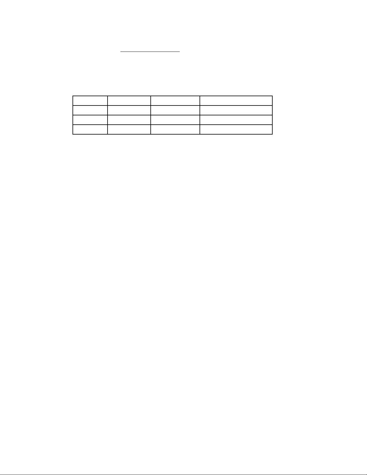
LabMax-Pro SSIM User Manual
For the latest Customer Service information, refer to our website:
www.Coherent.com.
Detailed instructions on how to prepare a product for shipping are
given under Product Shipping Instructions, below.
Table 6-1. Coherent Service Centers
Location Phone Fax E-mail
Europe +49-6071-968-0 +49-6071-968-499 [email protected]
Product Shipping Instructions
To prepare the product for shipping to Coherent:
1. Contact Coherent Customer Service (refer to T able 6-1, above)
for a Return Material Authorization number.
2. Attach a tag to the product that includes the name and address
of the owner, the person to contact, the serial number, and the
RMA number you received from Coherent Customer Service.
3. Wrap the product with polyethylene sheeting or equivalent
material.
4. If the original packing material and carton are not available,
obtain a corrugated cardboard shipping carton with inside
dimensions that are at least 6 in. (15 cm) taller, wider, and
deeper than the product. The shipping carton must be
constructed of cardboard with a minimum of 375 lb. (170 kg)
test strength. Cushion the instrument in the shipping carton
with packing material or urethane foam on all sides between
the carton and the product. Allow 3 in. (7.5 cm) on all sides,
top, and bottom.
5. Seat the shipping carton with shipping tape or an industrial
stapler.
6. Ship the product to:
Coherent, Inc.
27650 SW 95th Ave.
Wilsonville, OR 97070
Attn: RMA # (add the RMA number you received from
Coherent Customer Service)
6 - 4
Page 83

APPENDIX A: SPECIFICATIONS
Specifications
Meter Specifications
This appendix lists specifications for the LabMax-Pro SSIM Laser
Power Meter.
Table A-1. Specifications (Sheet 1 of 2)
Parameter Description
Measurement Resolution (%) (full-scale)
at 10 Hz speed
at 20 kHz high-speed
Sensor Compatibility PM Model Thermopile, PowerMax-Pro, LM Model Thermopile,
Measurement Range Sensor dependent (reference sensor specifications)
Accuracy (%)
Digital Meter
System
Analog Output
Calibration Uncertainty (%) (k = 2) ± 1
Power Sampling Rate
Thermopile (Hz)
PowerMax-Pro - Standard-Speed (Hz)
PowerMax-Pro - High-Speed (Hz)
PowerMax-Pro - Snapshot Mode (kHz)
Pyroelectric (Hz)
LM-2/OP-2 Optical (Hz)
Analog Output (VDC) 0 to 1, 2, or 4V (selectable)
Analog Output Resolution (mV) 1
Analog Output Update Rate (kHz) 19
Measurement Analysis
Computer Interface USB and RS-232
Pulse Triggering Internal and External
Temperature
Operating Range
Storage Range
Instrument Power (external supply) 90 to 260 VAC, 50/60 Hz
Compliance CE, RoHS, WEEE
Dimensions 105 x 105 x 32 mm (4.1 x 4.1 x 1.3 in.)
Weight 0.3 kg (0.6 lb.)
0.1
0.2
OP-2 & LM-2 Optical, and DB25 EnergyMax pyroelectric
± 1
Meter + sensor
± 1
10
10
20 kHz
625
10000
10
Trending, tuning, histog ram, data logging, statistics (min., max., mean,
range, std. dev., dose, stability), pulse shape and pulse energy (with
PowerMax-Pro in High-Speed and Snapshot mode), beam position
with LM Model thermopiles
5 to 40°C (41 to 104°F)
-20 to 70°C (-68 to 158°F)
A - 1
Page 84

LabMax-Pro SSIM User Manual
Table A-1. Specifications (Sheet 2 of 2)
Parameter Description
Front Panel Power switch
USB high-speed port (mini-B connector)
Trigger output (SMB connector)
Analog output (SMB connector)
RS-232 port (DB-9F connector)
Rear Panel DB-25 sensor port
External trigger input (SMB connector, 3 to 5 Vin, 2 to 10 mA,
50 ohm AC, 300 ohm DC impedance)
Power jack (12 VDC - center positive)
Part Number
a. Meter supplied with AC power adapter, power cord, USB cable, trigger cable, software and driver CD, and cer-
tificate of calibration.
a
1268881
Persistent Parameters
Refer to “Persistent Parameters” (p. 5-28).
A - 2
Page 85
Errors
APPENDIX B: ERRORS
Meter and Sensor Errors
Table B-1. Meter and Sensor Errors
Displayed Message Cause Corrective Action
AnnounceFaultsWindow One or more system faults have been
reported
Confirm Buffer Clear Trying to change the buffer size when
the buffer contains unsaved data
Hardware Incompatibility
Error
Standard Mode vs. Snapshot
Mode Conflict
Meter Reports Missing Data Data samples from the meter were
Meter’s User Settings
Restored to Default
Meter was disconnected Meter is not connected Connect the meter to the sensor and the PC
No Com Port Selected Com port not selected Select Com port
Snapshot Mode Setting
Conflict
Unable to launch Updater
Program
Unable to Open Meter on
COM1
Unexpected Error Encounter Unexpected error condition Reference the specific corrective action
Software is connected to a meter that has
obsolete firmware or hardware
De-selecting High-Speed mode in the
Home tab while Snapshot mode is
enabled in the Data Buffer tab.
marked with the Missing Data flag
Factory defaults are being overwritten
with non-factory default user settings.
Not all requirements have been met for
entering Snapshot mode
Software is unable to find the updater
application when you press the Check
for Updates button
Port not connected to a meter or another
application is using the port
Reference the specific corrective action
shown next to the error in the error message
Click OK to discard the data or Cancel to
preserve the data
Install newer firmware or software, or
install older software that is compatible
Press Yes to disable Snapshot mode and
change to Standard mode, or press No to
remain in High-Speed and Snapshot mode
None—missing data is not recoverable
Unplug the meter from the computer before
restoring the factory defaults.
Click Confirm Changes to make necessary
setting adjustment and enable Snapshot
mode, or click Cancel Request to leave all
settings unchanged
Reinstall the software.
Select an available Com port
shown next to the error in the error
message—unrecoverable errors require you
to exit the application
B - 1
Page 86

LabMax-Pro SSIM User Manual
B - 2
Page 87

INDEX
Index
A
Analog output 4-4
Applying wavelength compensation accuracy 3-8
C
Calibration 6-1
Coherent calibration facilities and capabilities 6-1
Commands and queries 5-6
Communications 5-9
Compatibility, sensor 4-2
Compliance
Export control laws ix
RoHS ix
Conformity, declaration of 1-2
D
Declaration of conformity 1-2
Description, sensor technology 3-6
E
Errors
Meter and sensor B-1
Record reporting and collection 5-9
Export control laws compliance ix
Extended warranty 6-2
External
Trigger input 4-2
Trigger output 4-4
F
Features
LabMax-Pro PC software 3-5
Product 3-4
Firmware, updates ix
G
Glossary, host interface 5-28
H
Hardware 4-1
Analog output 4-4
External trigger input 4-2
External trigger output 4-4
Power supply 4-2
Sensor compatibility 4-2
USB/RS-232 4-2
High-Speed mode 3-2
Host command quick reference 5-3
Host interface
Commands and queries 5-6
Communications 5-9
Error record reporting and collection 5-9
Measurement setup and control 5-12
SCPI common commands 5-6
System options 5-7
Glossary 5-28
Host command quick reference 5-3
Measurement, Data collection 5-22
Meter and probe device information 5-23
Persistent parameters 5-28, A-2
RS-232 interface, using 5-2
Special considerations 5-1
Message terminators 5-1
Syntax and notation conventions 5-2
Using the RS-232 interface 5-2
Using the USB interface 5-2
Syntax and notation conventions 5-2
USB interface, using 5-2
I
Initial setup instructions 2-1
Input, external trigger 4-2
Installation, software 2-1
Instructions
Initial setup 2-1
Product shipping 6-4
L
LabMax-Pro PC software features 3-5
Limitations, warranty 6-3
Limited warranty 6-2
M
Measurement
Data collection 5-22
High-Speed 2-6
Setup and control 5-12
Snapshot 2-9
Standard Speed 2-3
Meter
and probe device information 5-23
and sensor errors B-1
Specifications A-1
Mode
High-Speed 3-2
Snapshot 3-3
Standard-Speed 3-2
O
Obtaining service 6-3
Operating mode overview 3-2
Index - 1
Page 88

LabMax-Pro SSIM User Manual
High-Speed 3-2
Snapshot 3-3
Standard-Speed 3-2
Operation
Hardware 4-1
Output
Analog 4-4
External trigger 4-4
Overview, operating mode 3-2
P
Parameters, persistent A-2
Persistent parameters 5-28, A-2
Power supply 4-2
PowerMax-Pro sensors 3-7
Preface ix
Product
Compliance
Export control laws ix
RoHS ix
Features 3-4
Shipping instructions 6-4
Specifications A-1
Publication updates ix
Q
Quick
Reference, host command 5-3
Quick start
High-Speed measurement 2-6
Snapshot measurement 3-3
Standard-Speed measurement 2-3
R
RoHS compliance ix
RS-232, using 5-2
S
Safety 1-1
Declaration of conformity 1-2
Signal words and symbols in this manual vi i
Waste electrical and electronic equipment (WEEE,
2002) 1-2
SCPI common commands 5-6
Sensor
Compatibility 4-2
Technology description 3-6
PowerMax-Pro sensors 3-7
Thermopile sensors 3-6
Sensors, PowerMax-Pro 3-7
Service, obtaining 6-3
Signal words and symbols in this manual vii
Signal words vii
Symbols viii
Snapshot mode 3-3
Software installation 2-1
Specifications A-1
Meter A-1
Persistent parameters A-2
Standard-Speed mode 3-2
Supply, power 4-2
Syntax and notation conventions 5-2
System options 5-7
T
Taking
High-Speed measurements 2-6
Snapshot measurements 2-9
Standard-Speed measurements 2-3
Trigger
External circuit 4-4
U
Updates
Firmware ix
Publication ix
USB/RS-232 4-2
Using
RS-232 interface 5-2
USB interface 5-2
W
Warranty
Extended 6-2
Limitations 6-3
Limited 6-2
Waste electrical and electronic equipment (WEEE,
2002) 1-2
Wavelength compensation accuracy 3-8
Applying 3-8
Index - 2
Page 89

Page 90

LabMax-Pro SSIM User Manual
TM
©Coherent, Inc., 12/2014 (RoHS), printed in the USA
Part No. 1269224 Rev. AB
 Loading...