

Page 1
User Manual
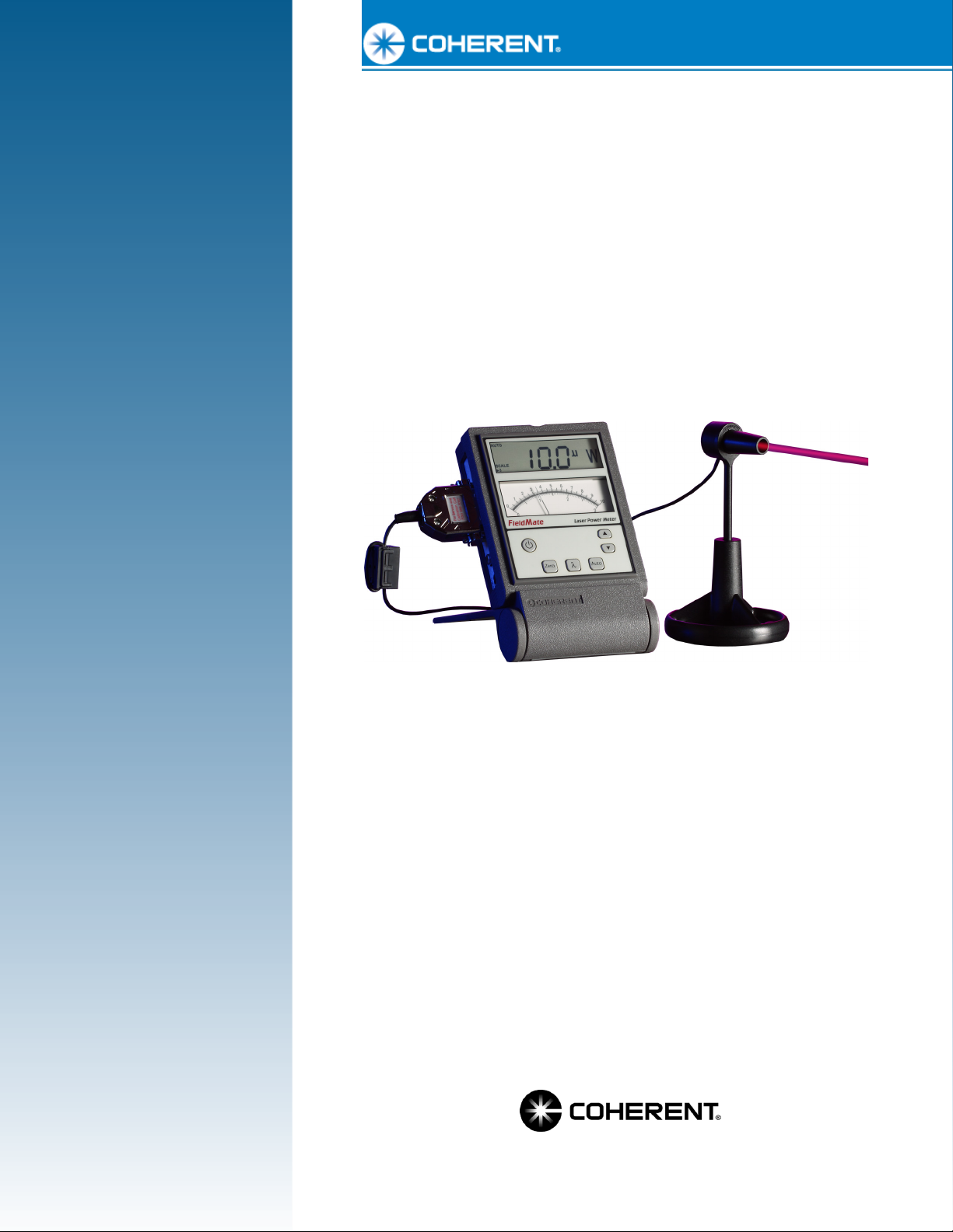
FieldMate
Laser Power Meter
™
Page 2

Page 3

User Manual
FieldMate
Laser Power Meter
27650 SW 95th Ave.
Wilsonville, OR 97070
Page 4

FieldMate User Manual
This document is copyrighted with all rights reserved. Under the copyright
laws, this document may not be copied in whole or in part or reproduced in
any other media without the express written permission of Coherent, Inc.
Permitted copies must carry the same proprietary and copyright notices as
were affixed to the original. This exception does not allow copies to be
made for others, whether or not sold, but all the material purchased may
be sold, given or loaned to another person. Under the law, copying
includes translation into another language.
Coherent, the Coherent Logo, and FieldMate are trademarks or registered
trademarks of Coherent, Inc. All other trademarks or registered
trademarks are the property of their respective owners.
Patents referenced in this User manual were active as of the printing date
of the manual (see last page for date). The patents referenced herein may
have expired. You are advised to check to see if the patents are still active:
http://portal.uspto.gov/external/portal/pair
Every effort has been made to ensure that the data given in this document
is accurate. The information, figures, tables, specifications and schematics
contained herein are subject to change without notice. Coherent makes no
warranty or representation, either expressed or implied with respect to this
document. In no event will Coherent be liable for any direct, indirect,
special, incidental or consequential damages resulting from any defects in
its documentation.
.
Technical Support
In the US:
Should you experience difficulties with your product, or need technical
information, please visit our website: www.Coherent.com
additional support by either telephoning our Technical Support Hotline at
1.800.343.4912, or e-mailing our Support Team at
Monday through Friday (except U.S. holidays).
If you call outside our office hours, your call will be taken by our answering
system and will be returned when the office reopens.
If there are technical difficulties with your product that cannot be resolved
by support mechanisms outlined above, please e-mail or telephone
Coherent Technical Support with a description of the problem and the
corrective steps attempted. When communicating with our Technical
Support Department via the web or telephone, the Support Engineer
responding to your request will require the model and serial number of the
product.
Outside the US:
If you are located outside the U.S., visit our website for technical
assistance, or telephone our local Service Representative. Representative
phone numbers and addresses can be found on the Coherent website:
www.Coherent.com
.
. Telephone coverage is available
. You can obtain
Coherent provides web and telephone technical assistance as a service to
its customers and assumes no liability thereby for any injury or damage
that may occur contemporaneous with such services. These support
services do not, under any circumstances, affect the terms of any warranty
agreement between Coherent and the buyer. Operating a Coherent
product with any of its interlocks defeated is always at the operator's risk.
ii
Page 5

Table of Contents
TABLE OF CONTENTS
Preface ....................................................................................................................................v
Export Control Laws Compliance ..........................................................................................v
Publication Updates ................................................................................................................v
Signal Words and Symbols in this Manual........................................................................... vi
Signal Words................................................................................................................ vi
Symbols ...................................................................................................................... vii
Section One: Safety......................................................................................................... 1-1
Waste Electrical and Electronic Equipment (WEEE, 2002)............................................... 1-2
Declaration of Conformity.................................................................................................. 1-2
Section Two: Description............................................................................................ 2-1
Meter Stand......................................................................................................................... 2-1
Front Panel.......................................................................................................................... 2-2
LCD ........................................................................................................................... 2-2
Analog Meter ............................................................................................................. 2-3
Buttons ....................................................................................................................... 2-4
Side Panel ........................................................................................................................... 2-4
Sensor Connector....................................................................................................... 2-5
Analog Out Connector ............................................................................................... 2-5
Power Connector........................................................................................................ 2-5
Battery Replacement........................................................................................................... 2-5
Battery Directive........................................................................................................ 2-5
Section Three: Operation ........................................................................................... 3-1
Controls............................................................................................................................... 3-1
Button Functions........................................................................................................ 3-1
Power ................................................................................................................ 3-1
Meter Zero Adjustment..................................................................................... 3-1
Zero................................................................................................................... 3-1
Wave ................................................................................................................. 3-2
Auto .................................................................................................................. 3-3
Up and Down Arrows ....................................................................................... 3-3
Display Functions ...................................................................................................... 3-3
Measurement Display ....................................................................................... 3-3
Annunciators..................................................................................................... 3-4
Power-Up Display............................................................................................................... 3-5
Fault Codes ......................................................................................................................... 3-5
Wavelength Edit .................................................................................................................3-6
Wavelength Edit Limits ............................................................................................. 3-6
iii
Page 6

FieldMate User Manual
Section Four: Special Topics .................................................................................... 4-1
Analog Output..................................................................................................................... 4-1
Negative Power Display ..................................................................................................... 4-1
Instrument Fault Response.................................................................................................. 4-1
Numeric Display Stationary Pattern ................................................................................... 4-2
Section Five: Calibration and Warranty .......................................................... 5-1
Calibration .......................................................................................................................... 5-1
Coherent Calibration Facilities and Capabilities ................................................................ 5-1
Limited Warranty................................................................................................................5-2
Extended Warranty ............................................................................................................. 5-2
Warranty Limitations.......................................................................................................... 5-3
Obtaining Service ...............................................................................................................5-3
Product Shipping Instructions............................................................................................. 5-4
Appendix A: Specifications....................................................................................... A-1
LIST OF FIGURES
1-1. Waste Electrical and Electronic Equipment Label .......................................................... 1-2
2-1. Meter Stand...................................................................................................................... 2-1
2-2. Front Panel....................................................................................................................... 2-2
2-3. LCD ................................................................................................................................. 2-2
2-4. Analog Meter ................................................................................................................... 2-3
2-5. Button Locations.............................................................................................................. 2-4
2-6. Side Panel ........................................................................................................................ 2-4
2-7. Battery Replacement........................................................................................................ 2-6
4-1. Numeric Display Stationary Pattern ................................................................................ 4-2
LIST OF TABLES
2-1. Batteries Contained in this Product ................................................................................. 2-5
3-1. Fault Codes ...................................................................................................................... 3-5
5-1. Coherent Service Centers................................................................................................. 5-4
A-1. Specifications.................................................................................................................. A-1
iv
Page 7

Table of Contents
Preface
Export Control Laws Compliance
This manual contains user information for the FieldMate™ laser
power meter.
It is the policy of Coherent to comply strictly with U.S. export
control laws.
Export and re-export of lasers manufactured by Coherent are subject
to U.S. Export Administration Regulations, which are administered
by the Commerce Department. In addition, shipments of certain
components are regulated by the State Department under the International Traffic in Arms Regulations.
The applicable restrictions vary depending on the specific product
involved and its destination. In some cases, U.S. law requires that
U.S. Government approval be obtained prior to resale, export or
re-export of certain articles. When there is uncertainty about the
obligations imposed by U.S. law, clarification must be obtained
from Coherent or an appropriate U.S. Government agency.
Products manufactured in the European Union, Singapore,
Malaysia, Thailand: These commodities, technology, or software are
subject to local export regulations and local laws. Diversion contrary
to local law is prohibited. The use, sale, re-export, or re-transfer
directly or indirectly in any prohibited activities are strictly prohibited.
Publication Updates
To view information that may have been added or changed since this
publication went to print, connect to www.Coherent.com.
v
Page 8

FieldMate User Manual
Signal Words and Symbols in this Manual
Signal Words
This documentation may contain sections in which particular
hazards are defined or special attention is drawn to particular conditions. These sections are indicated with signal words in accordance
with ANSI Z-535.6 and safety symbols (pictorial hazard alerts) in
accordance with ANSI Z-535.3 and ISO 7010.
Four signal words are used in this documentation: DANGER,
WARNING, CAUTION and NOTICE.
The signal words DANGER, WA R N IN G and CAUTION designate the degree or level of hazard when there is the risk of injury:
DANGER!
Indicates a hazardous situation that, if not avoided, will result in
death or serious injury. This signal word is to be limited to the
most extreme situations.
WARNING!
Indicates a hazardous situation that, if not avoided, could result
in death or serious injury.
CAUTION!
Indicates a hazardous situation that, if not avoided, could result
in minor or moderate injury.
The signal word “NOTICE” is used when there is the risk of property damage:
NOTICE!
Indicates information considered important, but not hazardrelated.
Messages relating to hazards that could result in both personal injury
and property damage are considered safety messages and not property damage messages.
vi
Page 9
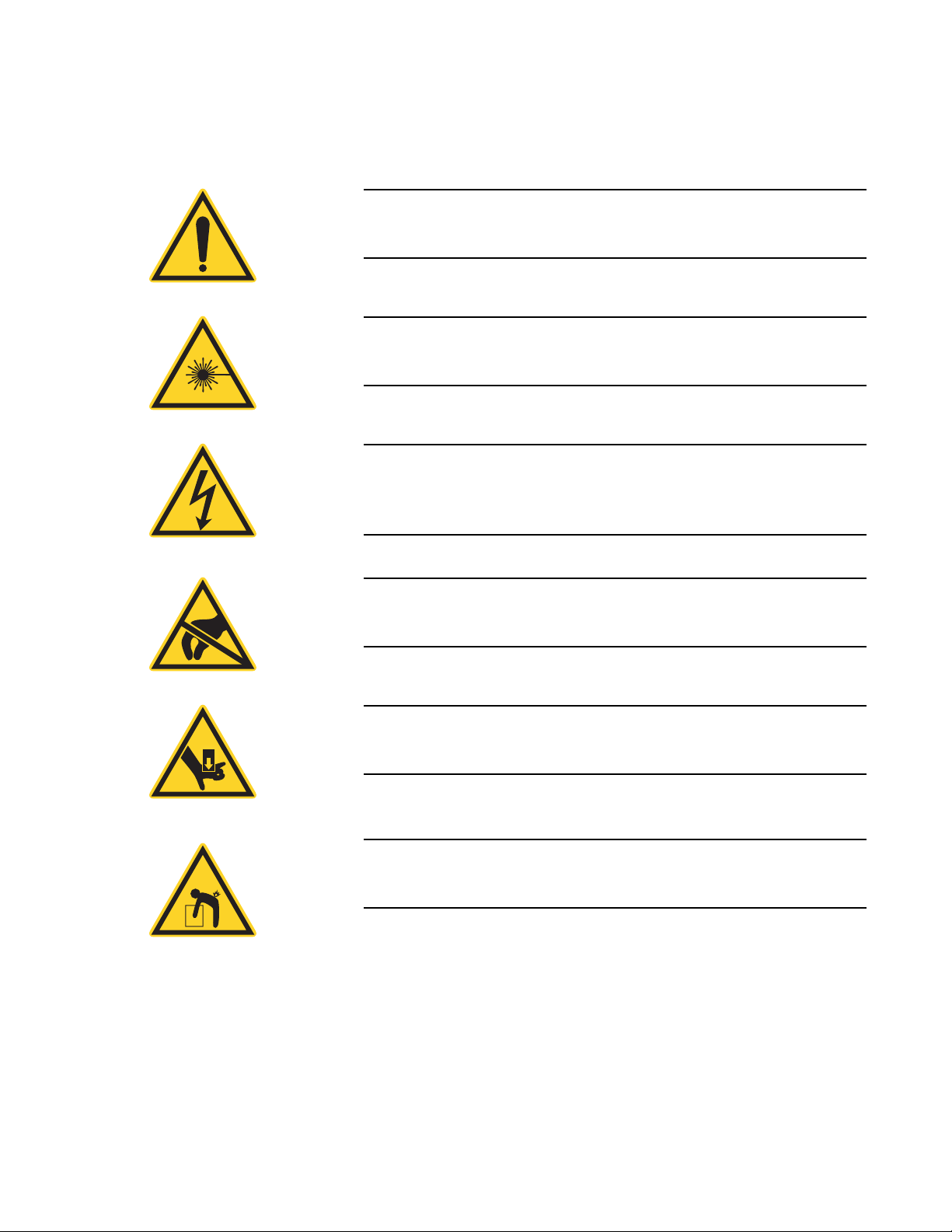
Table of Contents
Symbols
The signal words DANGER, WA R NI N G, and CAUTION are
always emphasized with a safety symbol that indicates a special
hazard, regardless of the hazard level:
This symbol is intended to alert the operator to the presence of
important operating and maintenance instructions.
This symbol is intended to alert the operator to the danger of
exposure to hazardous visible and invisible laser radiation.
This symbol is intended to alert the operator to the presence of
dangerous voltages within the product enclosure that may be of
sufficient magnitude to constitute a risk of electric shock.
This symbol is intended to alert the operator to the danger of
Electro-Static Discharge (ESD) susceptibility.
This symbol is intended to alert the operator to the danger of
crushing injury.
This symbol is intended to alert the operator to the danger of a
lifting hazard.
vii
Page 10

FieldMate User Manual
viii
Page 11

SECTION ONE: SAFETY
Carefully review the following safety information to avoid personal
injury and to prevent damage to this instrument or any sensor
connected to it. There are no user-serviceable parts in the FieldMate
laser power meter. For service information, refer to “Obtaining
Service” (p. 5-3).
WARNING!
Use only the power cord specified for the meter. The grounding
conductor of the cord must be connected to earth ground.
Safety
WARNING!
Do not operate the meter if its panels are removed or any of the
interior circuitry is exposed.
WARNING!
Do not operate the meter in wet or damp conditions, or in an
explosive atmosphere.
NOTICE!
Operate the meter only within the specified voltage range.
NOTICE!
Do not apply a voltage outside the specified range of the input
connections.
1 - 1
Page 12

FieldMate User Manual
NOTICE!
Do not operate the meter if there are suspected failures. Refer
damaged units to qualified Coherent service personnel.
Waste Electrical and Electronic Equipment (WEEE, 2002)
Figure 1-1. Waste Electrical and Electronic Equipment Label
Declaration of Conformity
The European Waste Electrical and Electronic Equipment (WEEE)
Directive (2002/96/EC) is represented by a crossed-out garbage
container label (see Figure 1, below). The purpose of this directive
is to minimize the disposal of WEEE as unsorted municipal waste
and to facilitate its separate collection.
Declaration of Conformity certificates are available upon request.
1 - 2
Page 13
SECTION TWO: DESCRIPTION
Thank you for purchasing the Coherent FieldMate™ laser power
meter—a versatile, easy-to-use meter designed for field service,
laser system production, and QA testing.
Specific features of FieldMate include:
• Intuitive soft key user interface.
• Works with thermopile and optical sensors.
• Fast analog tuning.
Description
Meter Stand
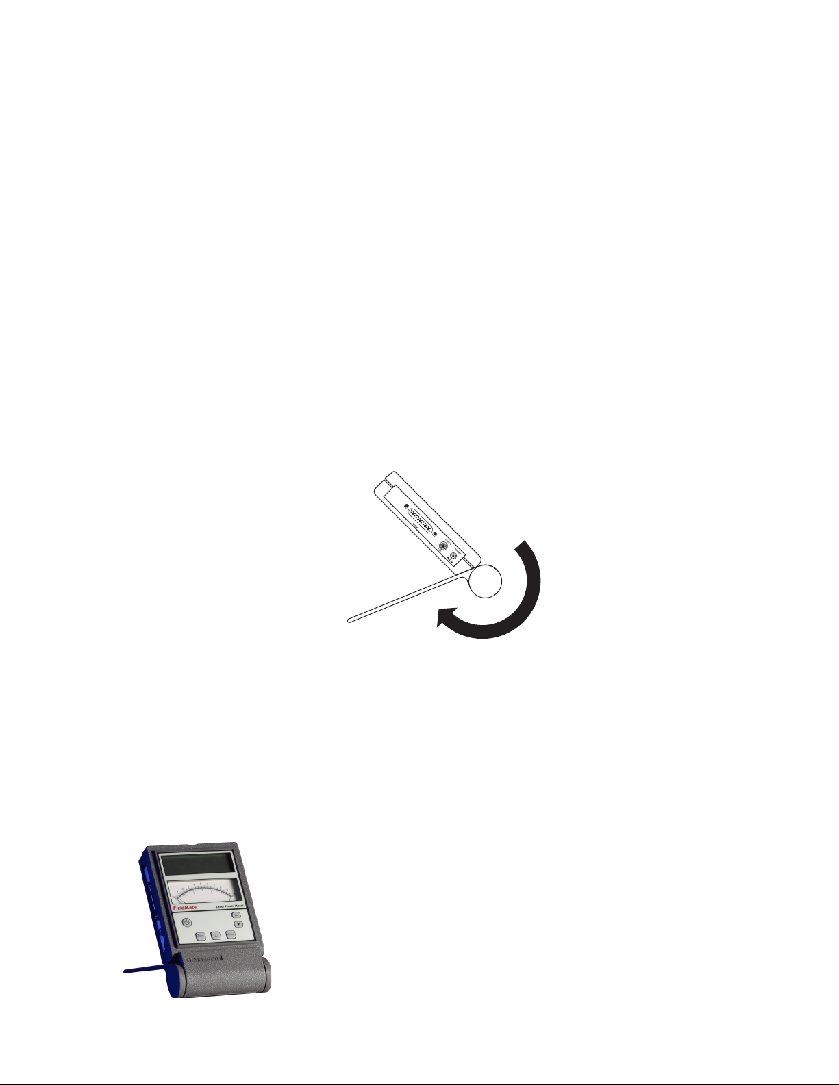
Figure 2-1 shows the attached meter stand in the open (operational)
position.
Figure 2-1. Meter Stand
2 - 1
Page 14
FieldMate User Manual
LCD
Buttons
Front Panel
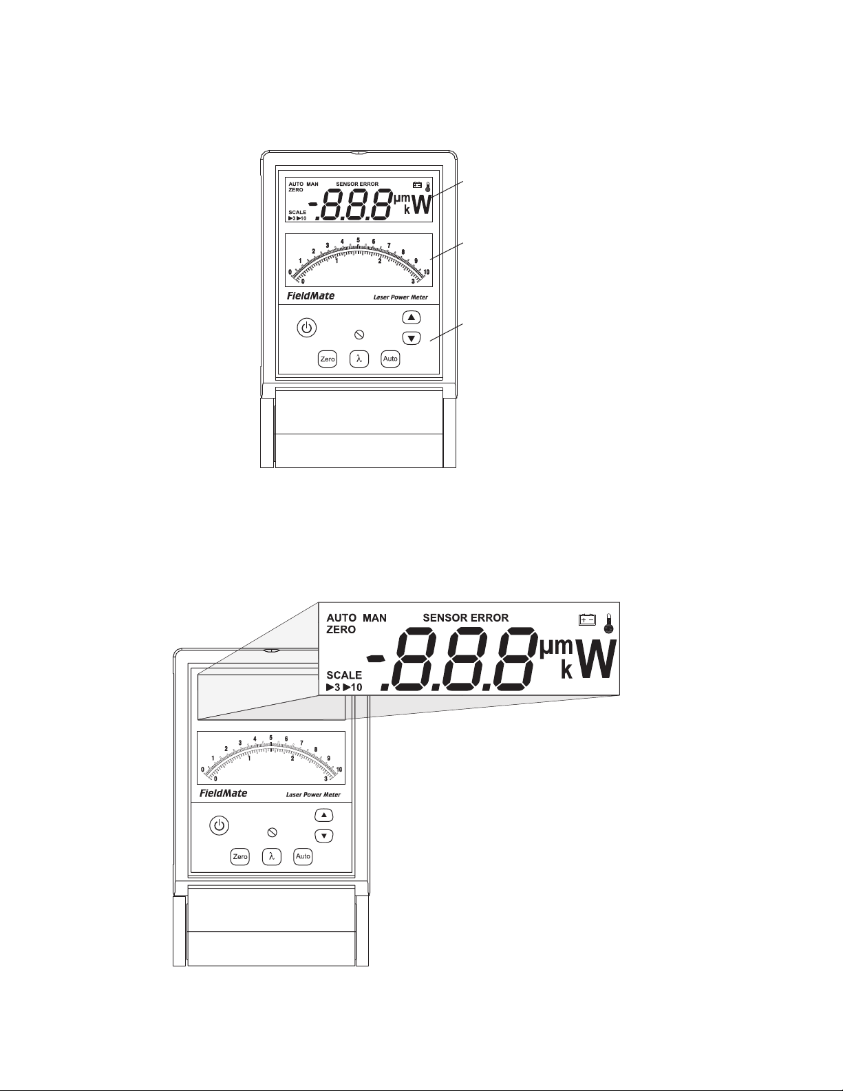
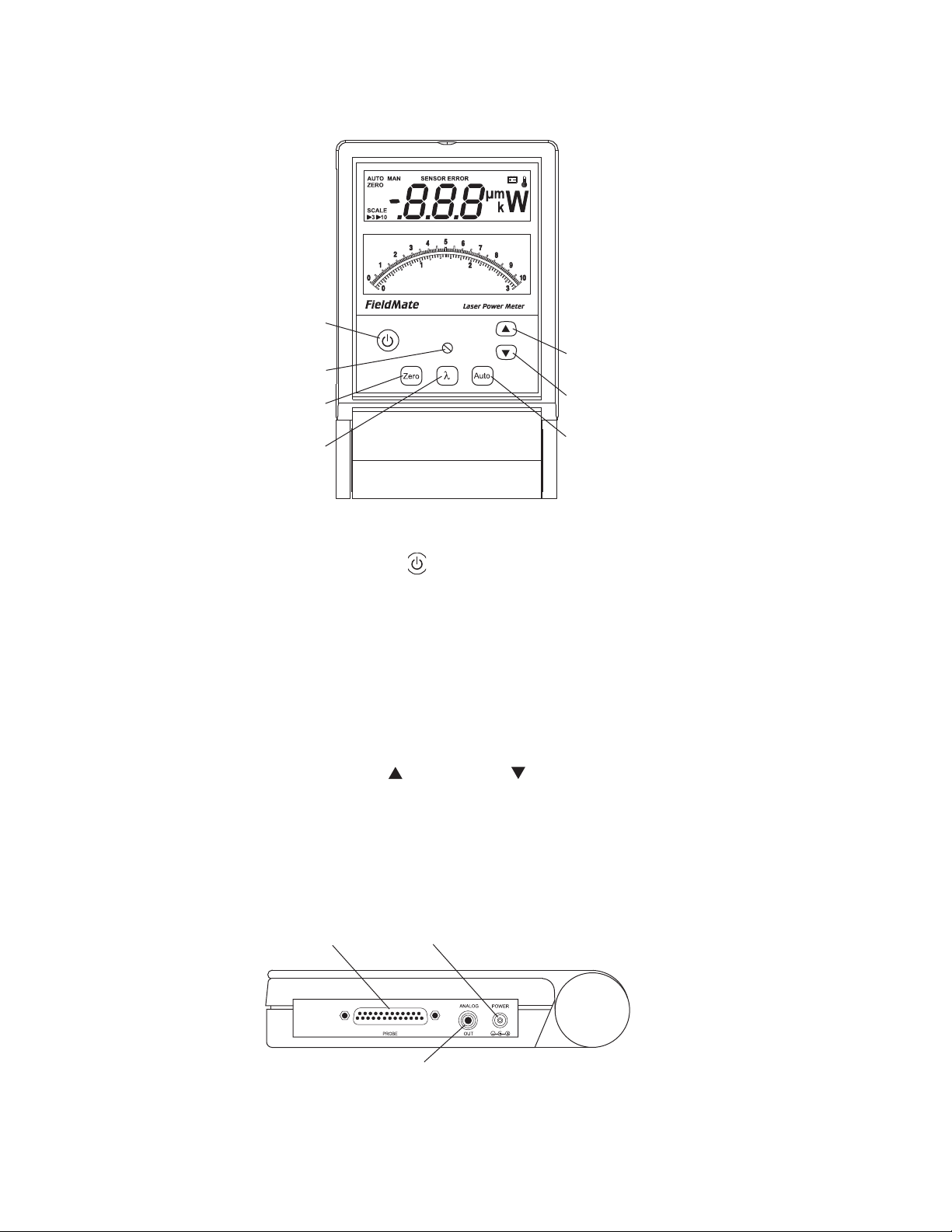
The front panel is organized as shown in Figure 2-2. The sensor,
analog out, and power connectors—all located on the side
panel—are shown in Figure 2-6 (p. 2-4).
Analog Meter
LCD
Figure 2-2. Front Panel
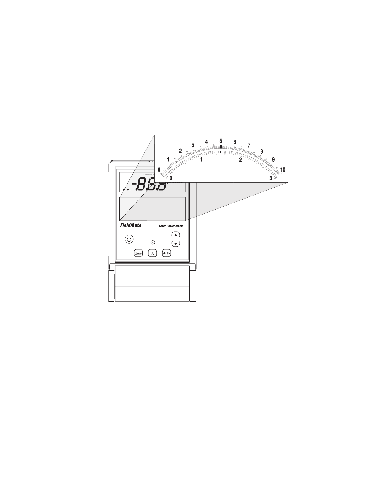
The LCD—along with the analog meter—provides measurement
information. Figure 2-3 shows all available annunciators and
segments that may appear on the LCD.
Figure 2-3. LCD
2 - 2
Page 15
Description
. ..
ZERO
SENSOR ERROR AUTO
MAN
SCALE
3 10
-
μm
k
W
SENSOR E
CALE
310
μm
k
W
“Annunciators” (p. 3-4) presents detailed information about each of
the annunciators. For information about the analog meter, refer to
“Analog Meter” (p. 2-3).
Analog Meter
The analog meter (Figure 2-4) is a mechanical meter with two
hash-marked scales (0 to 3, and 0 to 10). The currently-selected
analog scale (either 3 or 10) is indicated on the lower left side of the
LCD. For information on how to select a measurement scale for the
analog meter, refer to “Up and Down Arrows” (p. 3-3).
Figure 2-4. Analog Meter
For information about the digital display, refer to “LCD” (p. 2-2).
2 - 3
Page 16
FieldMate User Manual
Power
Zero
Wave
Up Arrow
Down
Arrow
Auto
Meter Zero
Adjustment
Buttons
Figure 2-5 shows the button locations on the front panel.
Figure 2-5. Button Locations
Side Panel
• Power ( ) - toggles power on and off.
• Meter Zero Adjustment - adjusts the analog meter to account
for mechanical offset.
• Zero - toggles Zero on/off (when an optical sensor is attached)
or zeros the sensor (when a thermopile sensor is attached).
• Wave (λ) - enters or exits Wavelength Edit mode.
• Auto - toggles Auto Ranging and Manual Ranging mode.
• Up ( ) and Down ( ) arrows - adjusts wavelength, selects
range, or toggles numeric display.
The side panel, as shown in Figure 2-6, contains the Sensor
connector, the Analog Out connector, and the Power connector.
Sensor Connector
Power Connector
Analog Out Connector
Figure 2-6. Side Panel
2 - 4
Page 17

Description
Sensor Connector
Analog Out Connector
Power Connector
Battery Replacement
Use this connection to attach a DB-25 SmartProbe connector or
adapter.
This RCA connector outputs a voltage proportional to the current
laser measurement. The voltage is scaled from 0.0V to 2.0V, with
2.0V representing full scale. The voltage is never less than 0.0V and
never greater than 2.0V.
Connect the power supply (included with the unit) to this barrel
connector. Depending on local power requirements, FieldMate ships
with a custom AC adapter. If the adapter is lost, contact Coherent for
a replacement.
FieldMate can operate on either one or two 9V alkaline or NiMH
batteries (refer to Table 2-1).
Battery Directive
The batteries used in this product are in compliance with the EU
Directive 2006/66/EC (“EU Battery Directive”).
Table 2-1. Batteries Contained in this Product
a
Number of
Batteries
1 46
2 92
1 97
2 194
Battery Type
Alkaline
NiMH
a. NiMH batteries may be used, but the
instrument will not recharge them.
Hours of
Operation
Dispose of batteries according to local regulations. Do
not dispose as normal waste. Consult your local waste
authorities for guidance.
2 - 5
Page 18
FieldMate User Manual
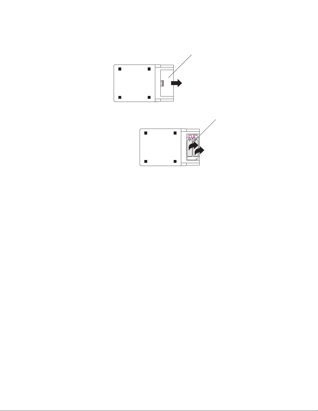
With the meter stand in the closed position, lay the meter
face down on a flat surface and remove the battery cover.
n
p
Insert new batteries and replace the battery cover.
o
Carefully remove the old batteries from the unit.
Figure 2-7 illustrates how to replace the batteries.
Figure 2-7. Battery Replacement
2 - 6
Page 19

SECTION THREE: OPERATION
In this section:
• Controls (this page)
• Power-up display (p. 3-5)
• Fault codes (p. 3-5)
• Wavelength edit (p. 3-6)
Operation
Controls
Button Functions
Power Pressing this button toggles meter power on/off.
Meter Zero Adjustment
Zero Pressing the Zero button implements the Zero function and sets the
The front panel display—shown in Figure 2-2 (p. 2-2)—is used to
acquire measurement information, obtain feedback during wavelength editing, view various operational modes, and detect error
conditions. These capabilities are discussed next.
This section describes the functions of each button and control.
This control adjusts the analog meter to account for mechanical
offset.
current sensor input as the baseline for future measurements. It is
recommended that you zero the meter after first turning it on and
before beginning any new set of power measurements.
If Auto Range mode is enabled, the meter automatically zeros all
available ranges for the attached sensor. In Manual Range mode,
each range needs to be zeroed independently. The meter does not
retain its zero values when it is turned off and then on again.
When a zero procedure is in process, no other button events are
queued or activated until the procedure ends. The zero procedure
immediately terminates if the sensor is disconnected or if an error is
encountered.
3 - 1
Page 20

FieldMate User Manual
Normally you should press the Zero button while the laser is turned
off, or while the laser beam is blocked. If a finite power level is
present at the sensor, the instrument will attempt to null it out.
The meter can only zero a finite level of offset. If zeroing on a
selected range is unsuccessful, the meter will display “E40,” indicating “Fault Code 40—Bad Zero.” For more information about
fault codes, refer to “Fault Codes” (p. 3-5).
If zeroing is unsuccessful—which means that the power input is
too large to null—re-zero in a more stable environment or select
a different range.
For information about the ZERO annunciator, refer to “ZERO”
(p. 3-4).
Wave Pressing the Wave button toggles between two modes: Edit
Wavelength and Measure. When in Edit Wavelength mode,
pressing the Up and Down arrow buttons allows selection of the
operational wavelength.
• Available wavelengths are set according to the wavelength
correction table in the sensor EEPROM. If there is no wavelength correction table in the sensor EEPROM, the wavelength
of operation automatically becomes the calibration wavelength and may not be adjusted.
• The decimal point of the wavelength is fixed.
• The longer an Up or Down arrow is pressed, the faster the
measurement changes.
Pressing the Wave button while in the Edit Wavelength mode selects
the adjusted wavelength and changes the mode from Edit to
Measure.
Whenever instrument power is turned off, FieldMate stores the last
wavelength used. The next time the instrument is powered up, that
same wavelength will be in effect. However, if another sensor is
attached to FieldMate while power is off, and the new sensor is out
of wavelength range, FieldMate uses the default calibration wavelength the next time power is restored.
(Optical sensors only) Changing the wavelength while in Zero
mode, automatically turns off Zero mode.
3 - 2
Page 21

Operation
Auto Pressing the Auto button toggles between Auto Ranging and Manual
Ranging mode. Auto Ranging mode instructs the FieldMate meter to
select the best measurement range for the incoming signal. Manual
Ranging mode requires the user to select the range.
Up and Down Arrows The Up and Down arrow buttons serve a dual purpose,
depending on which mode (Edit Wavelength or Measure) is
currently in use.
• Edit Wavelength mode: When in this mode, the Up and Down
arrow buttons allow adjustment of the wavelength of operation.
• Measure mode: In this mode, the buttons allow selection of the
measurement range (either 3 or 10), automatically cancel Auto
Ranging (if Auto is active) and, once Auto Ranging has been
cancelled, adjust the measurement range.
Display Functions
Measurement Display The display update rate for the display is three times per second.
Measurement range selection is dependent on the sensor type and
characteristics, as well as the wavelength of operation. If a display
value is greater than the maximum allowable level for the selected
range, over-ranging takes place. An “OL” (overload) appearing on
the display signifies an over-range condition. If over-ranging occurs
while in Manual Ranging mode, press the Up arrow until measurement data displays on the LCD.
With Auto Ranging, unless it is at the top range, the instrument
automatically ranges up, rather than go into an over-range
condition. If the measurement is above the maximum range
allowed by the sensor, an over-range condition will occur, even
while in Auto Ranging mode.
3 - 3
Page 22

FieldMate User Manual
Annunciators The update rate for all annunciators is three times per second.
Figure 2-3 (p. 2-2) shows all available annunciators that may appear
on the LCD.
AUTO and MAN
The AUTO and MAN annunciators indicate the instrument is either
in Auto Ranging or Manual Ranging mode.
ZERO
The ZERO annunciator indicates that the instrument is in Zero
mode. This annunciator does not appear when either of the following
conditions exist:
• An invalid sensor is attached to the instrument.
• The instrument is in a Non-Zero mode.
Thermopile sensors have a relative zero and, therefore, the ZERO
annunciator is not used with these types of sensors. For information
on the Zero button, refer to “Zero” (p. 3-1).
Optical sensors, on the other hand, use semiconductor diodes that
have an absolute zero reference. When an optical sensor is attached
to the instrument, pressing the Zero button causes the meter to toggle
between the Zero and the Non-Zero modes.
Scale
The Scale annunciator indicates which scale is to be used for the
analog meter (0 to 3, or 0 to 10).
SENSOR ERROR
If an invalid or unrecognized sensor is attached to the instrument, the
SENSOR ERROR annunciator and a series of three dashes will
display on the LCD. If this occurs, contact Customer Service for
support—refer to Table 5-1 (p. 5-4) for contact information.
Battery Low
A flashing Battery Low annunciator indicates the battery voltage is
low. From the time the annunciator first starts flashing, there are
approximately 12 hours (with alkaline batteries) or seven hours
(with NiMH batteries) of measurement time left. There is no change
in measurement accuracy—for either type battery—during the time
the Battery Low annunciator is flashing.
3 - 4
Page 23
Operation
Over-Temperature
(Thermopile sensors only) The Over-Temperature annunciator
flashes when FieldMate detects a sensor over-temperature condition.
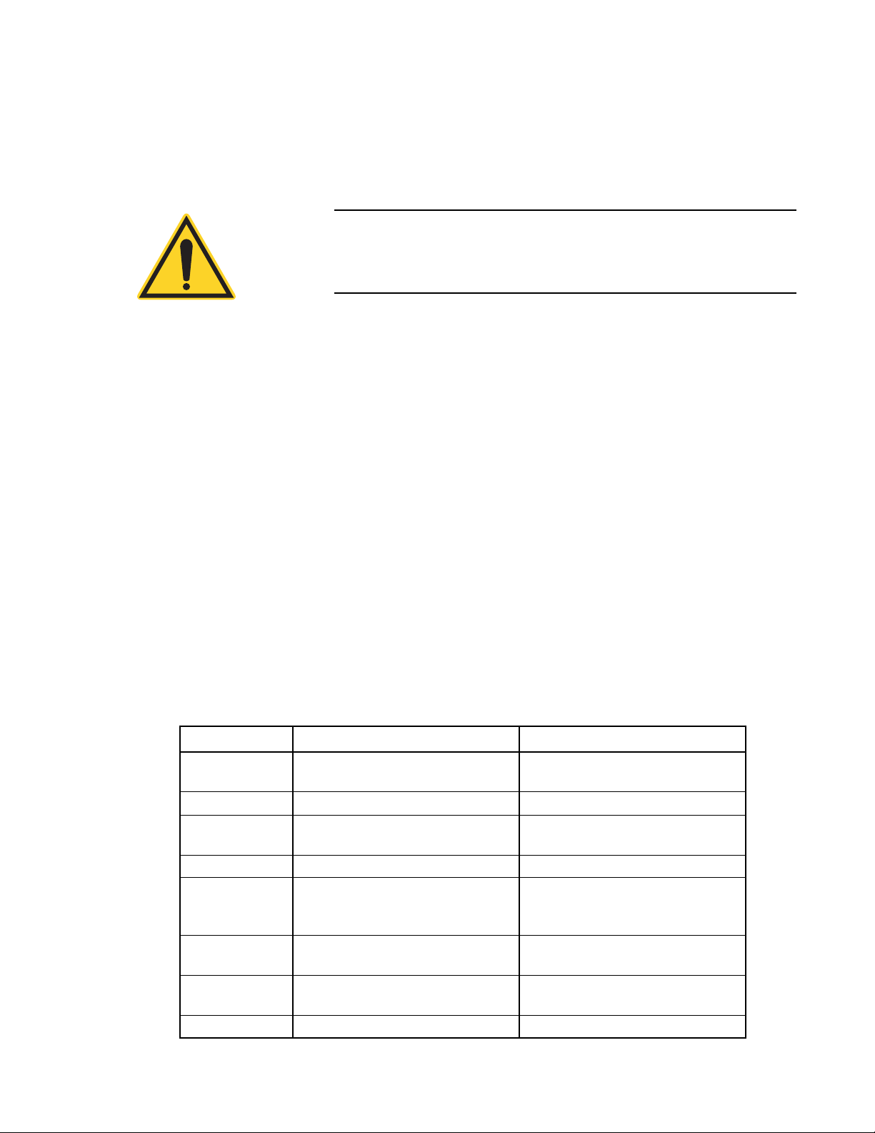
NOTICE!
If an Over-Temperature annunciator appears, IMMEDIATELY
turn off the laser to avoid damaging the sensor by overheating.
If the sensor does not seem to function correctly, contact Customer
Service for support—refer to Table 5-1 (p. 5-4) for contact information.
Power-Up Display
Fault Codes
Fault Code Fault Description Action Required
1
2 Sensor communication failure Return sensor for repair
3
4 Sensor checksum error Return sensor for repair
5
20
40 Bad zero
42 Wrong sensor type Attach valid sensor to the instrument
Pressing the Power button—refer to Figure 2-5 (p. 2-4)—powers up
the instrument. The firmware version is displayed until system
initialization is complete.
When FieldMate detects a fault, the letter “E” appears on the LCD,
followed by the appropriate numeric fault code. For example, if the
attached sensor has a bad checksum, the display will read “E 4".
Pressing any button—except the Power button—dismisses the
displayed fault code. Table 3-1 describes the fault codes and corrective action. For a description of the different classes of faults, refer
to “Instrument Fault Response” (p. 4-1).
Table 3-1. Fault Codes
Unrecognized sensor (unknown head
code)
Sensor NVRAM corrupt (invalid data
contained in the sensor)
Sensor/firmware version mismatch
(sensor format version exceeds capability of the instrument’s firmware)
Hardware fault (detectable hardware
error)
Return sensor for repair
Return sensor for repair
Return instrument for firmware
upgrade
Return instrument to Coherent for
repair
Reduce laser power or change instrument range
3 - 5
Page 24

FieldMate User Manual
Wavelength Edit
Wavelength Edit Limits
The wavelength appears on the LCD whenever the instrument is in
Edit Wavelength mode. The Up and Down arrow buttons—refer to
Figure 2-5 (p. 2-4)—allow the user to increase or decrease the
wavelength.
Pressing the Wave (λ) button when in Measure mode toggles to the
Edit Wavelength mode and initiates an edit cycle. Pressing the Wave
button a second time returns the instrument to Measure mode and
ends the edit cycle. Ending the edit cycle automatically commits the
current wavelength of operation to use. Pressing the Up and Down
arrow buttons during the edit cycle adjusts the wavelength. During
an edit cycle, all other button functions—except the Power
button—are disabled.
The wavelength limits are determined by the wavelength calibration
values stored in the sensor EEPROM. If the currently selected wavelength does not fall within the stored calibration values, the wavelength is automatically set to the calibration wavelength.
Wavelength selection is persistent, meaning calibration values
are stores between power cycles.
3 - 6
Page 25

SECTION FOUR: SPECIAL TOPICS
In this section:
• Analog output (this page)
• Negative power display (this page)
• Instrument fault response (this page)
• Numeric display stationary pattern (p. 4-2)
Special Topics
Analog Output
Negative Power Display
Instrument Fault Response
The Analog Output connector outputs a voltage proportional to the
current laser measurement. Full scale is indicated by 2.0V at the
analog output. Zero power is represented by 0.0V at the analog
output. Over-ranged measurements are indicated by a 2.0V output.
Negative power is indicated by 0.0V. Speedup is always applied to
the analog output when a thermopile sensor is attached.
Negative power—an indication that the sensor needs to be
zeroed—is displayed on the LCD.
This section describes the internal response of the instrument when
a fault is detected.
There are three classes of faults:
1. Sensor
2. Internal
3. Operational
Sensor faults are caused by various problems with sensor identification or data stored in the sensor EEPROM. A sensor fault effectively
results in an invalid sensor state. FieldMate does not permit
measurement when a faulty sensor is attached.
Internal faults result from some detectable failure of hardware or
software. If the fault is firmware related, power cycling—that is,
either using the Power button or removing and reinstalling the
batteries—may remedy the problem. If the meter is not functioning,
4 - 1
Page 26

FieldMate User Manual
and you have replaced the batteries and cycled the power, then the
instrument may have a hardware-related fault. Contact Customer
Service for support—refer to Table 5-1 (p. 5-4) for contact information.
Operational faults occur due to operator error. When an operational
fault is dismissed, operation continues as if the fault had never
happened.
Refer to “Fault Codes” (p. 3-5) for a list of fault conditions and what
action to take to correct them.
Numeric Display Stationary Pattern
Some users prefer to turn off the digital numerals while tuning lasers
in a production setting. Fieldmate has an operating mode that temporarily replaces the numeric display with a stationary pattern (shown
in Figure 4-1). Pressing the Up and Down arrow buttons simultaneously for longer than one second activates this stationary pattern. To
switch back to viewing the numbers, both arrow buttons must again
be simultaneously pressed for longer than one second. The numeric
display toggle function is not available when the Wavelength Edit
cycle is in progress. While the stationary pattern is visible, the range
change function associated with the Up and Down arrow buttons is
disabled and the annunciators behave as explained under “Annunciators” (p. 3-4).
This display mode is persistent, meaning it will return to this
mode after cycling power.
Figure 4-1. Numeric Display Stationary Pattern
4 - 2
Page 27

Calibration and Warranty
SECTION FIVE: CALIBRATION AND WARRANTY
In this section:
• Calibration (this page)
• Coherent calibration facilities and capabilities (this page)
• Limited warranty (p. 5-2)
• Extended warranty (p. 5-2)
• Warranty limitations (p. 5-3)
• Obtaining service (p. 5-3)
• Product shipping instructions (p. 5-4)
Calibration
Coherent Calibration Facilities and Capabilities
Coherent laser power and energy meters are precision instruments,
capable of delivering very accurate measurements, as well as
providing many years of useful service. To maintain this high level
of performance, it is important to have your measurement system
serviced and recalibrated once a year.
As the largest laser manufacturer in the world, Coherent has been
able to build state-of-the-art calibration facilities containing the
widest possible range of laser types and technologies. This enables
us to perform instrument and sensor calibration under virtually any
combination of wavelength, power, and operating characteristics.
Sensors are calibrated against NIST-traceable working standard
sensors which are, in turn, calibrated against NIST-calibrated golden
standard sensors. These working and golden standards are maintained with the utmost care, recalibrated annually, and verified even
more regularly. We maintain multiple NIST-calibrated standards at
many laser wavelengths to support the growing calibration needs of
our customers. Optical calibration is a core competency at Coherent
and we strive to continually improve our methods, precision, and
repeatability. Additionally, most of the calibrations are performed
with highly automated systems, thus reducing the possibility of
human error to nearly zero. Strict quality inspections during many
stages of calibration and testing assure a precise and accurate instrument that is NIST traceable and CE marked. The benefit to our
customers is that instruments calibrated by Coherent will consis-
5 - 1
Page 28

FieldMate User Manual
tently perform as expected under their actual use conditions. We are
a registered ISO 9001:2000 company, our products are NIST traceable, and our calibration labs are fully ANSI Z540 compliant.
In addition to the technological advantage, we also strive to deliver
the best service in the industry, with a knowledgeable and responsive
staff, and rapid turnaround.
Limited Warranty
Extended Warranty
Coherent, Inc. (the “Company”) warrants its laser power and energy
meters and sensors products (“Products”) to the original purchaser
(the “Customer”) that the product is free from defects in materials
and workmanship and complies with all specifications, active at the
time of purchase, for a period of twelve (12) months.
Coherent, Inc. will, at its option, repair or replace any product or
component found to be defective during the warranty period. This
warranty applies only to the original purchaser and is not transferable.
Coherent, Inc. (the “Company”) offers original purchasers (the
“Customer”) purchasing laser power and energy meters and sensors
products (“Products”) an extended twelve (12) month warranty
program, which includes all parts and labor. In order to qualify for
this warranty, a Customer must return the Product to the Company
for recalibration and recertification. The Company will recertify the
Product, provide software upgrades, and perform any needed
repairs, and recalibrate the Product, for a fixed service fee (as established by the Company from time to time and in effect at the time of
service). If the product cannot be recertified due to damage beyond
repair, parts obsolescence, or other reasons, the Customer may be
informed that an Extended Warranty program is not available for the
Product.
If the Product fails and is returned to the Company within one year
following the date of recalibration and recertification service, the
Company will, at its option, repair or replace the Product or any
component found to be defective. If the Product must be replaced
and the Product is no longer available for sale, Coherent reserves the
right to replace with an equivalent or better Product. This warranty
applies only to the original purchaser and is not transferable.
5 - 2
Page 29

Calibration and Warranty
Warranty Limitations
The foregoing warranties shall not apply, and Coherent reserves the
right to refuse warranty service, should malfunction or failure result
from:
• Damage caused by improper installation, handling, or use.
• Laser damage (including sensor elements damaged beyond
repair).
• Failure to follow recommended maintenance procedures.
• Unauthorized product modification or repair.
• Operation outside the environmental specifications of the
product.
Coherent assumes no liability for Customer-supplied material
returned with Products for warranty service or recalibration.
THIS WARRANTY IS EXCLUSIVE IN LIEU OF ALL OTHER
WARRANTIES WHETHER WRITTEN, ORAL, OR IMPLIED.
COHERENT SPECIFICALLY DISCLAIMS THE IMPLIED
WARRANTIES OF MERCHANTABILITY AND FITNESS FOR
A PARTICULAR PURPOSE. IN NO EVENT SHALL THE
COMPANY BE LIABLE FOR ANY INDIRECT, INCIDENTAL,
OR CONSEQUENTIAL DAMAGES IN CONNECTION WITH
ITS PRODUCTS.
Obtaining Service
In order to obtain service under this warranty, Customer must notify
the Company of the defect before the expiration of the warranty
period and make suitable arrangements for the performance of
service. The Company shall, in its sole discretion, determine
whether to perform warranty service at the Customer's facility, at the
Company's facility or at an authorized repair station.
If Customer is directed by the Company to ship the product to the
Company or a repair station, Customer shall package the product (to
protect from damage during shipping) and ship it to the address
specified by the Company, shipping prepaid. The customer shall pay
the cost of shipping the Product back to the Customer in conjunction
with recalibration and recertification; the Company shall pay the
cost of shipping the Product back to the Customer in conjunction
with product failures within the first twelve months of time of sale
or during an extended twelve month warranty period.
A Returned Material Authorization number (RMA) assigned by the
Company must be included on the outside of all shipping packages
and containers. Items returned without an RMA number are subject
to return to the sender.
5 - 3
Page 30

FieldMate User Manual
Location Phone Fax E-Mail
For the latest Customer Service information, refer to our website:
www.Coherent.com.
Detailed instructions on how to prepare a product for shipping are
shown under “Product Shipping Instructions,” below.
Table 5-1. Coherent Service Centers
Product Shipping Instructions
To prepare the product for shipping to Coherent:
1. Contact Coherent Customer Service—refer to Table 5-1,
above—for a Return Material Authorization number.
2. Attach a tag to the product that includes the name and address
of the owner, the person to contact, the serial number, and the
RMA number you received from Coherent Customer Service.
3. Wrap the product with polyethylene sheeting or equivalent
material.
4. If the original packing material and carton are not available,
obtain a corrugated cardboard shipping carton with inside
dimensions that are at least 6 in. (15 cm) taller, wider, and
deeper than the product. The shipping carton must be
constructed of cardboard with a minimum of 375 lb. (170 kg)
test strength. Cushion the instrument in the shipping carton
with packing material or urethane foam on all sides between
the carton and the product. Allow 3 in. (7.5 cm) on all sides,
top, and bottom.
5. Seal the shipping carton with shipping tape or an industrial
stapler.
6. Ship the product to:
Coherent, Inc.
27650 SW 95th Ave.
Wilsonville, OR 97070
Attn: RMA # (add the RMA number you received from
Coherent Customer Service)
5 - 4
Page 31

APPENDIX A: SPECIFICATIONS
Table A-1 lists specifications for the FieldMate.
Table A-1. Specifications (Sheet 1 of 3)
Parameter Description
General
External Power Supply (included) 90 to 260 VAC, 50/60 Hz
Instrument Power Input
Sensor Input Connector DB-25
Update Rate
Primary Digits
Analog Meter
Analog Output
Icons
Performance
Input
9V Alkaline or NiMH (x 2)
12 VDC (center positive plug)
>= 3 times/sec.
>= 20 times/sec.
>= 20 times/sec.
>= 3 times/sec.
1.8V max. (thermopile)
25 mA max. (optical)
Specifications
Measurement Range (full scale)
Display Power
Measurement Resolution Power
Accuracy
Digital Display
System
Analog Meter
Analog Out
Analog Meter
Meter Response
Meter Scale
Analog Output
Full Scale Voltage
Noise
Resolution
Update Rate
29.9 mW to 29.9 kW (thermopile)
2.99 nW to 99.9 mW (optical)
± 0.1% of full scale (thermopile and optical). All ranges in
10s scale.
± 0.3% of full scale (thermopile and optical). All ranges in
3s scale.
± 1.0% of reading ± 2 LSD (Least Significant Digit)
Display unit + sensor accuracy
± 3.0%
± 1.0%
Tau = 80 ms (2 Hz)
0 to 3, 60 divisions, and 0 to 10, 100 divisions.
2.0 VDC full scale on the current range
< 1 mV P-P
< 0.1%
20 times a second
a
A - 1
Page 32

FieldMate User Manual
Parameter Description
Standard Uncertainty
Digital Display
Environmental
Temperature
Operating
Storage
Relative Humidity (non-condensing)
Operating
Storage
Altitude
Operating
Storage
Shock and Vibration
EMC
EN55011
EN55011
EN61000-4-2
EN61000-4-3
EN61000-4-4
EN61000-4-5
EN61000-4-6
EN61000-4-11
EN61000-3-3
Miscellaneous
Regulations Met CE
Table A-1. Specifications (Sheet 2 of 3)
± 0.8%
5 to 40°C (41 to 104°F)
-20 to 70°C (-4 to 158°F)
0 to 90%
0 to 95%
-100 to 2,000 m
-100 to 4,000 m
Complies with MIL-PRF-28800F Class 3 (or Class 2 drip
proof)
Meets the intent of Directive 89/336/EEC, using
applicable parts of EN61326
Class A Radiated Emissions
Class A Conducted Emissions
Electrostatic Discharge - Performance Criteria B
(Unit may respond to an ESD event but will return to
normal operation without user intervention.)
Radiated Immunity - Performance Criteria A
Electrical Fast Transient Immunity - Performance
Criteria A
Electrical Slow Transient Immunity (Performance
Criteria A
Conducted RF Immunity - Performance Criteria A
Power Line Dropout - Performance Criteria A
Powerline Fluctuation & Flicker Emission
A - 2
Page 33

Table A-1. Specifications (Sheet 3 of 3)
Parameter Description
Safety
Complies with EU Directive 92/59/EEC
Designed and tested to EN61010-1-2001
Pollution Degree2
Installation Category II
Equipment Class I (single insulation/Earthed
metal case
Protection against water ingress IP4X (general
indoor conditions)
Input circuitry and connections (creepage and
clearances)
Designed to interface at Installation or
Measurement Category I
Efficacy
Meets or exceeds IEC 61040-1990 Class 1
Physical Characteristics
Size (h x w x d) 19.3 x 11.7 x 4.6 cm (7.6 x 4.6 x 1.8 in.)
Weight (including battery) 0.8 kg (1.75 lb.)
Display (viewing area) (h x w) 26.2 x 88.9 mm (1.0 x 3.5 in.) fixed-segment LCD
b
Specifications
a. When using a PM2 model thermopile sensor in the 9.99 mW range, the accuracy is ± 1.0% and
± 5 LSD with no averaging. While in the 2.99 mW range, the accuracy with this sensor is ± 1.0%
and ± 10 LSD.
b. Meter meets or exceeds IEC 61040-1990 Class 1. Meter and sensor system meet or exceed IEC
61040-1990 Class 5.
A - 3
Page 34

FieldMate User Manual
A - 4
Page 35

Page 36

FieldMate™ User Manual
©Coherent, Inc., 5/2013 (RoHS), printed in the USA
Part No. 1062446 Rev. AF
 Loading...