

Page 1
®
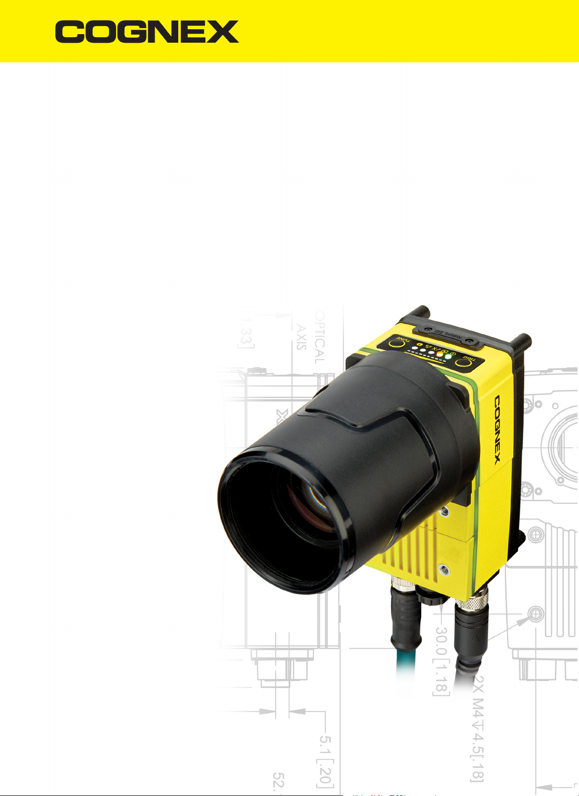
In-Sight
9902L
Vision System
Reference Guide
2018 July 19
Revision:5.6.1.39
Page 2

Legal Notices
Legal Notices
The software described in this document is furnished under license, and may be used or copied only in accordance with
the terms of such license and with the inclusion of the copyright notice shown on this page. Neither the software, this
document, nor any copies thereof may be provided to, or otherwise made available to, anyone other than the licensee.
Title to, and ownership of, this software remains with Cognex Corporation or its licensor. Cognex Corporation assumes
no responsibility for the use or reliability of its software on equipment that is not supplied by Cognex Corporation.
Cognex Corporation makes no warranties, either express or implied, regarding the described software, its
merchantability, non-infringement or its fitness for any particular purpose.
The information in this document is subject to change without notice and should not be construed as a commitment by
Cognex Corporation. Cognex Corporation is not responsible for any errors that may be present in either this document or
the associated software.
Companies, names, and data used in examples herein are fictitious unless otherwise noted. No part of this document
may be reproduced or transmitted in any form or by any means, electronic or mechanical, for any purpose, nor
transferred to any other media or language without the written permission of Cognex Corporation.
Copyright © 2018. Cognex Corporation. All Rights Reserved.
Portions of the hardware and software provided by Cognex may be covered by one or more U.S. and foreign patents, as
well as pending U.S. and foreign patents listed on the Cognex web site at: http://www.cognex.com/patents.
The following are registered trademarks of Cognex Corporation:
Cognex, 2DMAX, Advantage, AlignPlus, Assemblyplus, CheckitwithChecker, Checker, CognexVisionforIndustry,
CognexVSOC, CVL, DataMan, DisplayInspect, DVT, EasyBuilder, Hotbars, IDMax, In-Sight, LaserKiller, MVS-8000,
OmniView, PatFind, PatFlex, PatInspect, PatMax, PatQuick, SensorView, SmartView, SmartAdvisor, SmartLearn,
UltraLight, VisionSolutions, VisionPro, VisionView
The following are trademarks of Cognex Corporation:
The Cognex logo, 1DMax, 3D-Locate, 3DMax, BGAII, CheckPoint, CognexVSoC, CVC-1000, FFD, iLearn, In-Sight
(design insignia with cross-hairs), In-Sight2000, InspectEdge, Inspection Designer, MVS, NotchMax, OCRMax,
PatMaxRedLine, ProofRead, SmartSync, ProfilePlus, SmartDisplay, SmartSystem, SMD4, VisiFlex, Xpand
Portions copyright © Microsoft Corporation. All rights reserved.
Portions copyright © MadCap Software, Inc. All rights reserved.
Other product and company trademarks identified herein are the trademarks of their respective owners.
2
Page 3
Regulations and Conformity
Regulations and Conformity
Note: For the most up-to-date CE declaration and regulatory conformity information, please refer to the Cognex
online support site: http://www.cognex.com/Support.
Safety and Regulatory
Manufacturer
Cognex Corporation
One Vision Drive
Natick, MA 01760 USA
Regulatory Model 1AA9
FCC
KCC Regulatory Model 1AA9: R-REM-CGX-1AA9
NRTL TÜV SÜD AM SCC/NRTL OSHA Scheme for UL/CAN 61010-1.
CB TÜV SÜD AM, IEC/EN 61010-1. CB report available upon request.
EU RoHS Compliant to the latest applicable Directive.
FCC Part 15, Class A
This device complies with Part 15 of the FCC Rules. Operation is subject to the following two
conditions: (1) this device may not cause harmful interference; and (2) this device must accept any
interference received, including interference that may cause undesired operation. This equipment
generates, uses, and can radiate radio frequency energy and, if not installed and used in accordance
with the instruction manual, may cause harmful interference to radio communications. Operation of this
equipment in a residential area is likely to cause harmful interference in which case the user will be
required to correct the interference at their own expense.
3
Page 4
Regulations and Conformity
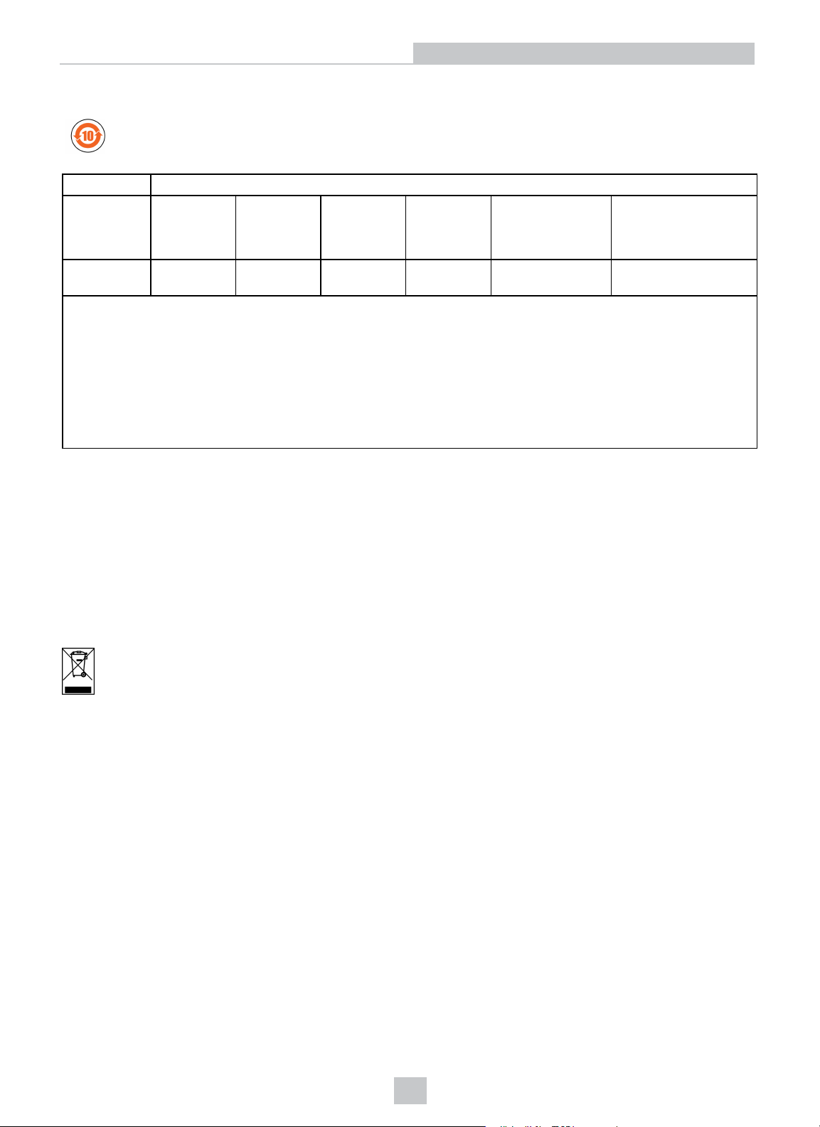
China RoHS
Hazardous Substances 有害物 质
Part Name
部件名 称
Regulatory
Model 1AA9
This table is prepared in accordance with the provisions of SJ/T 11364.
这个标 签 是 根据SJ / T 11364 的 规 定 准备的。
O: Indicates that said hazardous substance contained in all of the homogeneous materials for this part is below the limit
requirement of GB / T26572 - 2011.
表示本 部 件 所有均质材 料 中 含 有的有害物 质 低 于GB / T26572 - 2011 的限量要求 。
X: Indicates that said hazardous substance contained in at least one of the homogeneous materials used for this part is
above the limit requirement of GB / T26572 - 2011.
表示用 于 本 部件的至少 一 种 均 质材料中所 含 的 危害物质超 过 GB / T26572 - 2011 的 限 制要求。
Lead (Pb)铅Mercury (Hg)汞Cadmium
(Cd)
镉
X O O O O O
Hexavalent
Chromium
(Cr (VI))
六价铬
Polybrominated
biphenyls (PBB)
多溴联 苯
Polybrominated
diphenyl ethers (PBDE)
多溴二 苯 醚
For European Community Users
Cognex complies with Directive 2012/19/EU OF THE EUROPEAN PARLIAMENT AND OF THE COUNCIL of 4 July 2012
on waste electrical and electronic equipment (WEEE).
This product has required the extraction and use of natural resources for its production. It may contain hazardous
substances that could impact health and the environment, if not properly disposed.
In order to avoid the dissemination of those substances in our environment and to diminish the pressure on the natural
resources, we encourage you to use the appropriate take-back systems for product disposal. Those systems will reuse or
recycle most of the materials of the product you are disposing in a sound way.
The crossed out wheeled bin symbol informs you that the product should not be disposed of along with municipal
waste and invites you to use the appropriate separate take-back systems for product disposal.
If you need more information on the collection, reuse, and recycling systems, please contact your local or regional waste
administration.
You may also contact your supplier for more information on the environmental performance of this product.
4
Page 5

Precautions
Precautions
To reduce the risk of injury or equipment damage when you install the Cognex product, observe the following
precautions:
l The vision system requires a UL or NRTL listed power supply with a 24VDC output and meets the following rating
requirements:
l At least 2A continuous current.
l A maximum short circuit current of less than 8A.
l A maximum power of less than 100VA and marked as a Limited Power Source (LPS) or National
Electrical Code (NEC) Class 2.
Any other voltage creates a risk of fire or shock and can damage the components. Applicable national and local
wiring standards and rules must be followed.
l To reduce the risk of damage or malfunction due to over-voltage, line noise, electrostatic discharge (ESD), power
surges, or other irregularities in the power supply, route all cables and wires away from high current wiring or
high-voltage power sources.
l Do not install Cognex products where they are directly exposed to environmental hazards such as excessive
heat, dust, moisture, humidity, impact, vibration, corrosive substances, flammable substances, or static electricity.
l Do not expose the image sensor to laser light; image sensors can be damaged by direct, or reflected, laser light.
If your application requires the use of laser light that may strike the image sensor, a lens filter at the
corresponding laser's wavelength is recommended. Contact your local integrator or application engineer for
suggestions.
l Changes or modifications not expressly approved by the party responsible for regulatory compliance could void
the user’s authority to operate the equipment.
l Service loops should be included with all cable connections.
l Cable shielding can be degraded or cables can be damaged or wear out more quickly if a service loop or bend
radius is tighter than 10X the cable diameter. The bend radius must begin at least six inches from the connector.
l The LIGHT connector is not supported.
l This device is certified for office use only and if used at home, there can be frequency interference problems.
l This device should be used in accordance with the instructions in this manual.
l All specifications are for reference purpose only and may be changed without notice.
5
Page 6
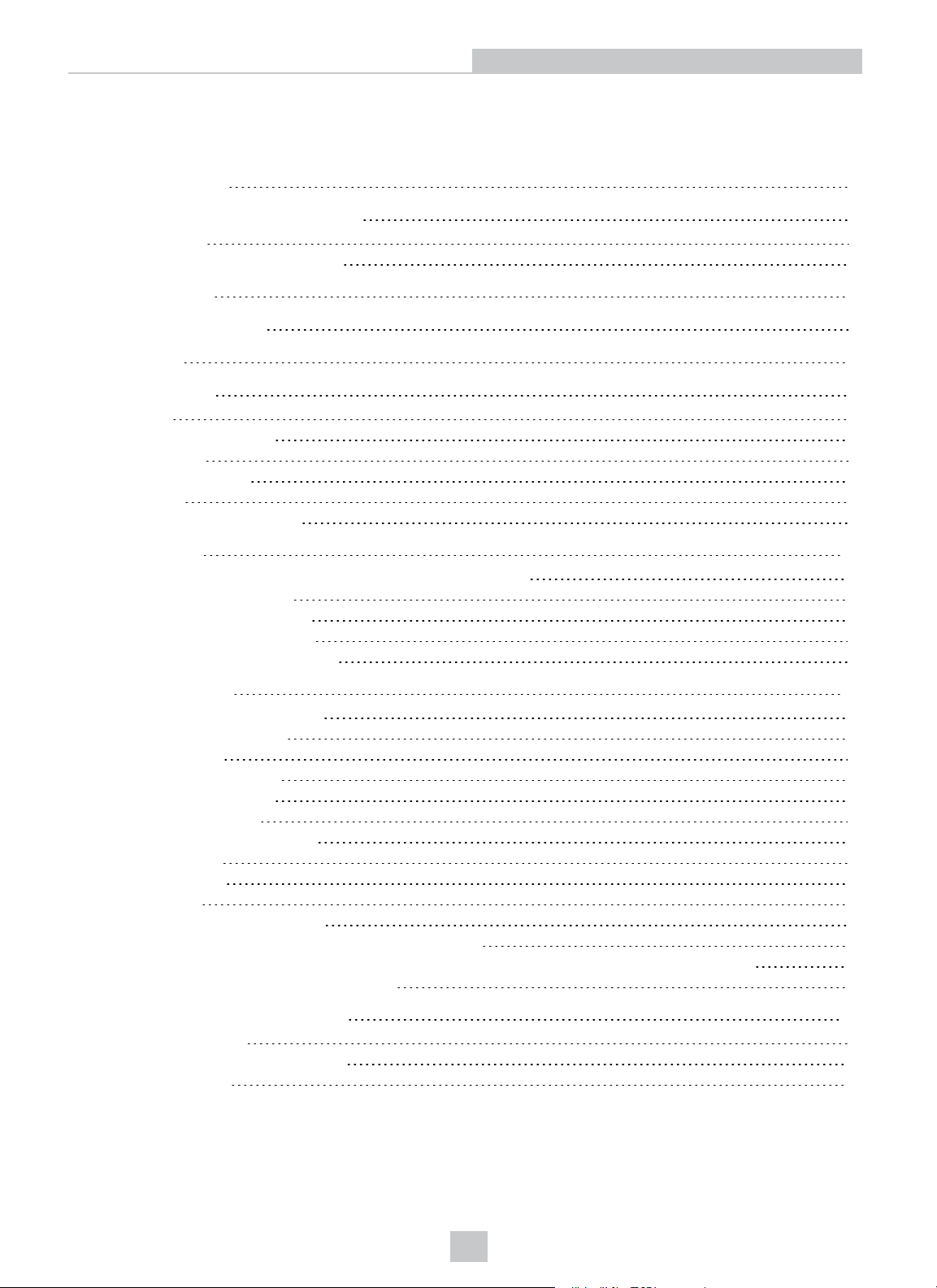
Table of Contents
Table of Contents
Legal Notices 2
Regulations and Conformity 3
China RoHS 4
For EuropeanCommunity Users 4
Precautions 5
Table of Contents 6
Symbols 7
Introduction 8
Support 8
Standard Components 8
Accessories 9
C-Mount Covers 9
Cables 9
Connectors and Indicators 10
Installation 12
Install the C-Mount Lens and Cover (COV-7000-CMNT-LG) 12
Mount the Vision System 13
Connect the Ethernet Cable 14
Connect the Breakout Cable 15
Replace the SD Card (Optional) 16
Specifications 17
Vision System Specifications 17
Acquisition Trigger Input 19
Encoder Inputs 20
Encoder Input Wiring 20
General-Purpose Input 21
High-Speed Outputs 22
High-Speed Output Wiring 23
Ethernet Cable 24
Breakout Cable 25
Dimensions 26
Vision System Dimensions 26
Vision System with Cover (COV-7000-CMNT-LG) 27
Vision System with Cover (COV-7000-CMNT-LG) and Extender (COV-7000-CMNT-LGX) 28
C-Mount Lens Clearance Dimensions 29
Cleaning and Maintenance 30
Clean the Housing 30
Clean the Image Sensor Window 30
Clean the Cover 30
6
Page 7
Symbols
The following symbols indicate safety precautions and supplemental information.
WARNING: This symbol indicates the presence of a hazard that could result in death, serious personal injury or
electrical shock.
CAUTION: This symbol indicates the presence of a hazard that could result in property damage.
Note: Notes provide supplemental information about a subject.
Tip: Tips provide helpful suggestions and shortcuts that may not otherwise be apparent.
Symbols
7
Page 8
Introduction
Introduction
The In-Sight®vision system is a compact, network-ready, stand-alone machine vision system used for automated
inspection, measurement, identification and robot guidance applications on the factory floor. All models can be easily
configured remotely over a network using an intuitive user interface.
Support
Many information resources are available to assist you in using the vision system:
l The In-Sight
l On-demand training: http://www.cognex.com/on-demand-training.aspx.
l The In-Sight online support site: http://www.cognex.com/Support/InSight.
Standard Components
Note:
l Cables are sold separately.
l If any of the standard components appear to be missing or damaged, immediately contact your Cognex
Authorized Service Provider (ASP) or Cognex Technical Support.
®
Explorer Help and EasyBuilder Help files, provided with In-Sight Explorer software.
Component Description
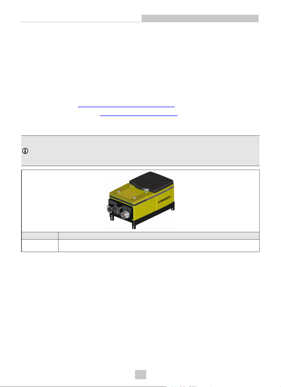
Vision System
Provides image acquisition, vision processing, job storage, Ethernet connectivity and discrete I/O.
The vision system has an 8GB SD card pre-installed.
8
Page 9
Introduction
Accessories
The following components can be purchased separately. For a complete list of options and accessories, contact your
local Cognex sales representative.
C-Mount Covers
Note:
l A C-Mount lens has the following restrictions:
l Maximum thread length is 5.25mm.
l The C-Mount lens threads and body cannot protrude more than 6.5mm in length into the vision
system when screwed in, unless the diameter of the back lens is smaller than 19.25mm. If the CMount lens threads and body protrude more than 6.5mm, you can add a spacer between the lens
and vision system. However, the spacer decreases the working distance.
l Refer to C-Mount Lens Clearance Dimensions on page29 for more information.
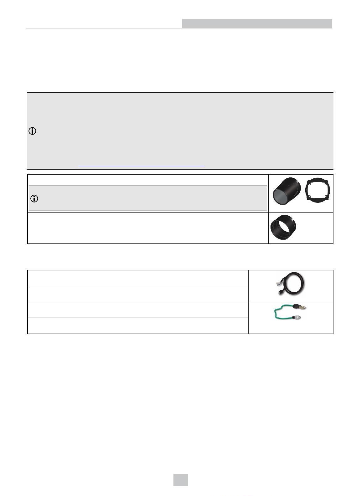
Large C-Mount cover and adapter (COV-7000-CMNT-LG).
Note: If using the COV-7000-CMNT-LG cover, the maximum lens length is 77mm with a
bandpass filter, the maximum lens body diameter is 55mm and the maximum diameter
including locking screws is 55mm.
C-Mount cover extender (COV-7000-CMNT-LGX).
Cables
Breakout cable, M12-12 to Flying Lead (CCB-PWRIO- xx) (straight, xx specifies
length: 5m, 10m, 15m)
Breakout cable, M12-12 to Flying Lead (CCB-PWRIO-xxR) (right-angled, xx specifies
length: 5m, 10m, 15m)
Ethernet X-coded M12-8 to RJ-45 cable (CCB-84901-2001-xx) (straight, xx specifies
length: 2m, 5m, 10m, 15m, 30m)
Ethernet X-coded M12-8 to RJ-45 cable (CCB-84901-2002) (right-angled, xx
specifies length: 2m, 5m, 10m)
9
Page 10
Connectors and Indicators
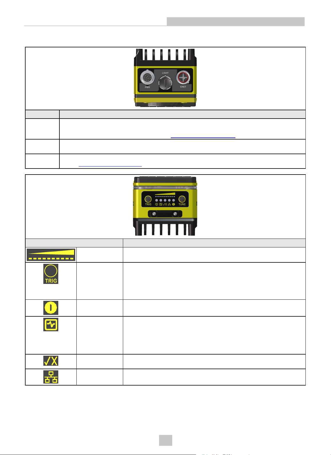
Connector Function
PWR
Connector
LIGHT
Connector
ENET
Connector
Connects the Breakout cable, which provides connections to an external power supply, the acquisition
trigger input, encoder inputs, general-purpose input, high-speed outputs and RS-232 serial
communications. For more information, refer to
Breakout Cable on page25
Not supported.
Connects the Ethernet cable, which provides 10/100/1000 Ethernet connectivity. For more information,
refer to Ethernet Cable on page24.
Introduction
.
Indicator Function
Focus Metric
LEDs
TRIG Button
Indicates the image focus score (0 - 10) while in Live Video Mode within
In-Sight Explorer.
Manually triggers an image acquisition when the vision system is either:
l Online within In-Sight Explorer and the acquisition Trigger parameter
is set to Manual.
l Offline within In-Sight Explorer.
Power LED The green LED illuminates to indicate that the vision system is powered on.
SD Card Status
l Off: The SDcard is not inserted.
LED
l Green: The SD card is present, and it is safe to remove the SD card
after removing power from the vision system.
l Yellow: The SD card is present, but it is not safe to remove it.
Pass/Fail LED and
Green or red when active. User configurable.
Indicator Ring
Network LED The yellow LED flashes to indicate network activity.
10
Page 11
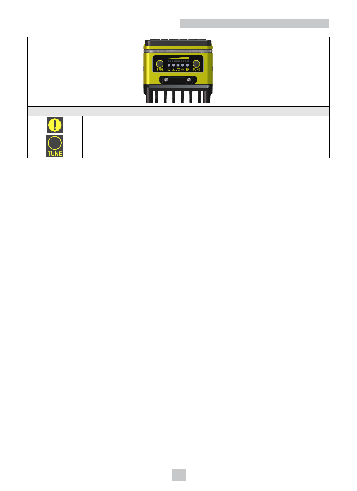
Indicator Function
Error LED Red when active. User configurable.
Introduction
TUNE Button
Used as an Event Trigger within In-Sight Explorer to force a cell containing
an Event structure to run when the TUNEbutton is pressed.
11
Page 12
Installation
Installation
This section describes the connection of the vision system to its standard components and accessories. For a complete
list of options and accessories, contact your Cognex sales representative.
Note: Cables are sold separately.
CAUTION: All cable connectors are “keyed” to fit the connectors on the vision system; do not force the connections
or damage may occur.
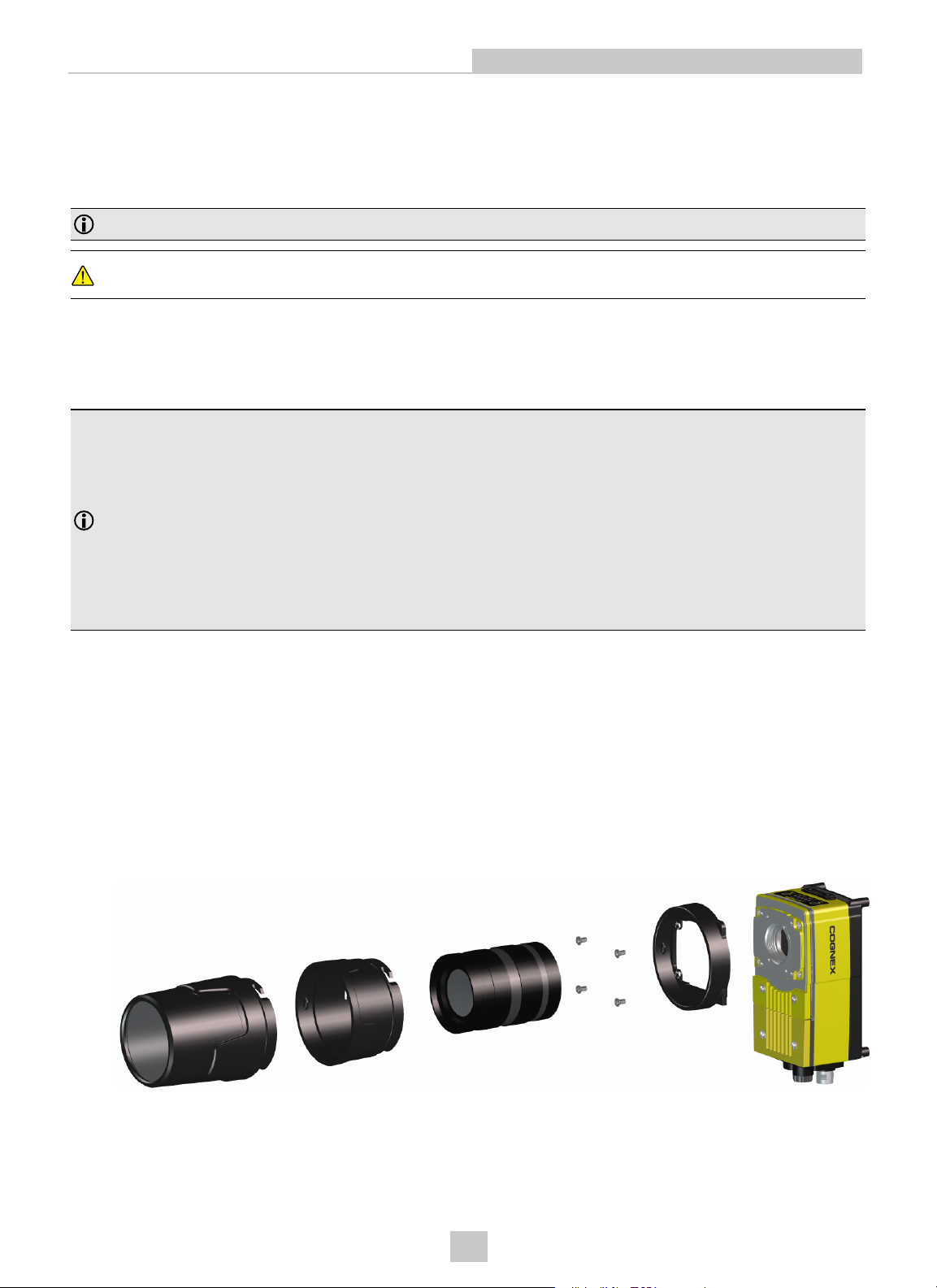
Install the C-Mount Lens and Cover (COV-7000-CMNT-LG)
Complete the following steps to install a C-Mount lens and cover to the vision system. The C-Mount cover (COV-7000CMNT-LG) is an optional accessory and required for IP67 protection.
Note:
l A C-Mount lens has the following restrictions:
l Maximum thread length is 5.25mm.
l The C-Mount lens threads and body cannot protrude more than 6.5mm in length into the vision
system when screwed in, unless the diameter of the back lens is smaller than 19.25mm. If the CMount lens threads and body protrude more than 6.5mm, you can add a spacer between the lens
and vision system. However, the spacer decreases the working distance.
l If using the COV-7000-CMNT-LG cover, the maximum lens length is 77mm with a bandpass filter, the
maximum lens body diameter is 55mm and the maximum diameter including locking screws is 55mm.
1. Remove the rubber faceplate covering the image sensor window, if present.
2. Remove the protective film covering the threaded lens opening, if present.
3. Place the adapter on the faceplate of the vision system. Insert the four adapter screws and tighten; the maximum
torque is 0.90 Nm (8 in-lb).
4. Thread the lens into the vision system.
5. (Optional) For longer lenses, the C-Mount cover extender accessory (COV-7000-CMNT-LGX) can be used to add
30mm in length to the C-Mount cover. If using the cover extender, attach it to the vision system and rotate the
cover extender clockwise approximately thirteen degrees to lock it.
6. Attach the cover to the vision system. Rotate the cover clockwise approximately thirteen degrees to lock it.
12
Page 13
Installation
Mount the Vision System
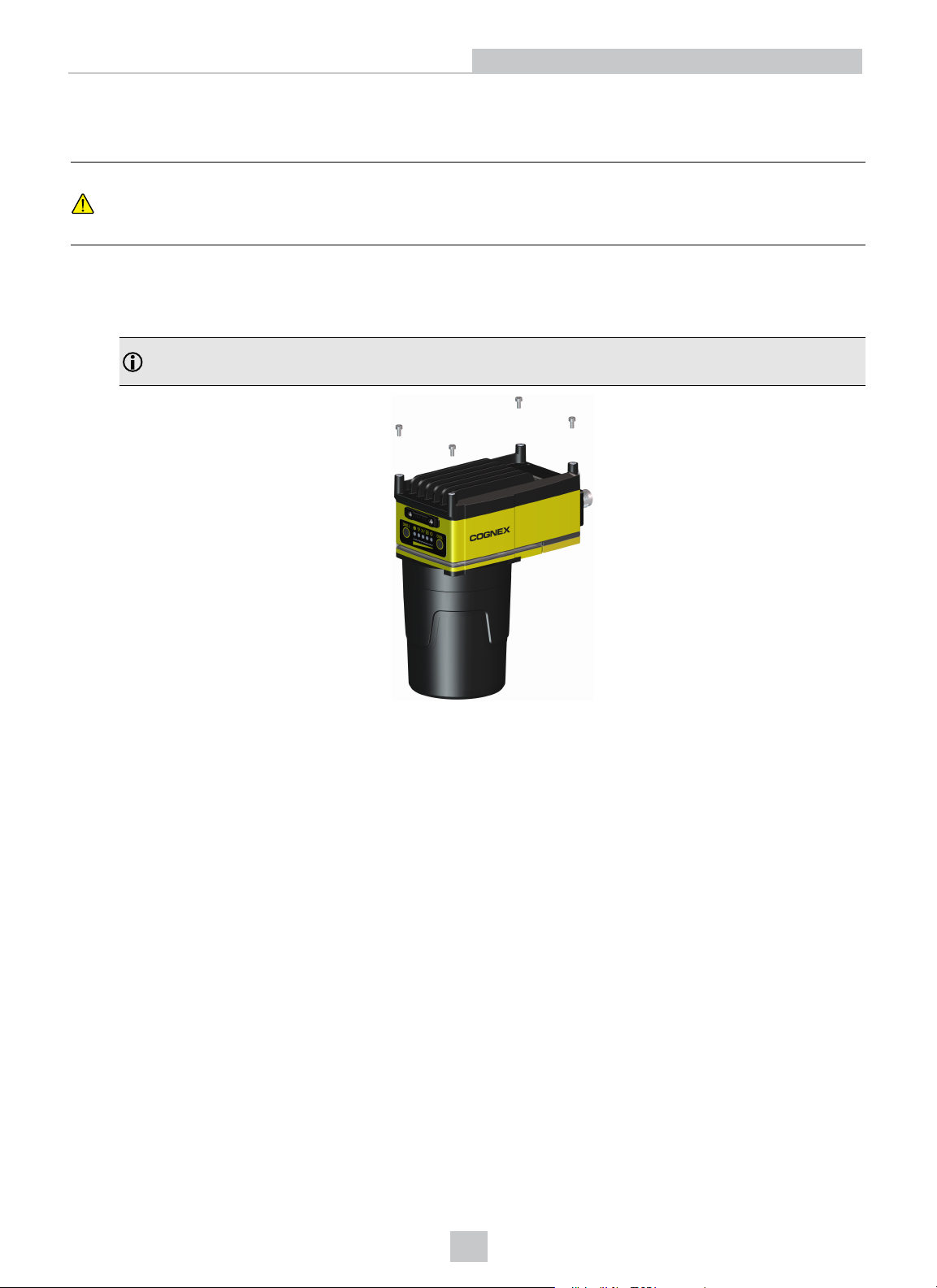
The vision system provides mounting holes for attachment to a mounting surface.
CAUTION: The vision system should be grounded, either by mounting the vision system to a fixture that is
electrically grounded or by attaching a wire from the vision system’s mounting fixture to frame ground or Earth
ground. If a ground wire is used, it should be attached to one of the four mounting points on the back plate of the
vision system and not to the mounting points on the front of the vision system.
1. Align the holes on the mounting surface with the mounting holes on the vision system.
2. Insert the M4 screws into the mounting holes and tighten using a 2.5mm hex wrench; the maximum torque is 0.90
Nm (8 in-lb).
Note: The maximum insertion depth of the M4 screws should be 6mm in the rear housing and 3.75mm in the
front housing, plus the thickness of the mounting material used.
13
Page 14
Installation
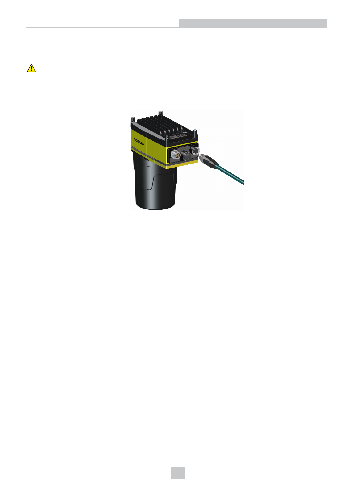
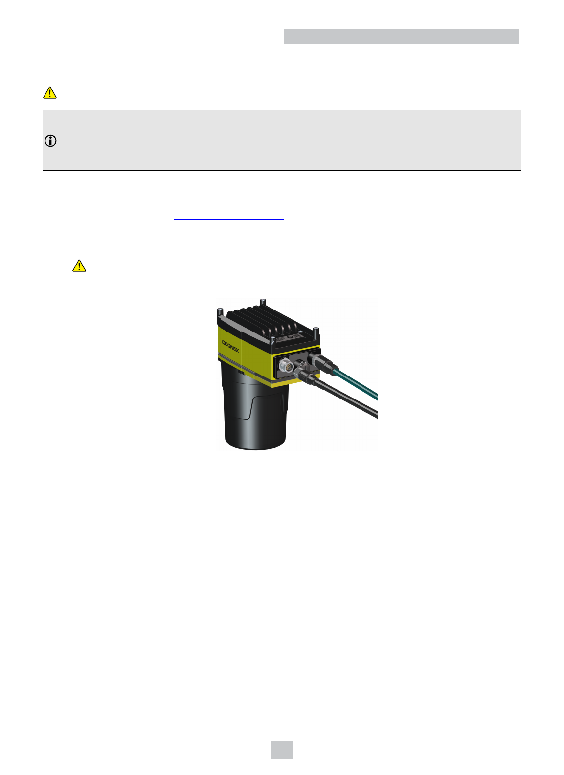
Connect the Ethernet Cable
CAUTION: The Ethernet cable shield must be grounded at the far end. Whatever this cable is plugged into
(typically a switch or router) should have a grounded Ethernet connector. A digital voltmeter should be used to
validate the grounding. If the far end device is not grounded, a ground wire should be added in compliance with
local electrical codes.
1. Connect the Ethernet cable’s M12 connector to the vision system’s ENET connector.
2. Connect the Ethernet cable’s RJ-45 connector to a switch/router or PC, as applicable.
14
Page 15
Installation
Connect the Breakout Cable
CAUTION: To reduce emissions, connect the far end of the Breakout cable shield to frame ground.
Note:
l Perform wiring or adjustments to I/O devices when the vision system is not receiving power.
l Exposed wires can be cut short or wire ends trimmed, and the wires tied back using a tie made of non-
conductive material. Keep all bare wires separated from the +24VDC wire.
1. Verify that the 24VDC power supply being used is unplugged and not receiving power.
2. Optionally, connect the I/O wires to an appropriate device (for example, a PLC, encoder or serial device). For
more information, refer to Breakout Cable on page25.
3. Attach the Breakout cable's +24VDC (Red wire) and GND (Black wire) to the corresponding terminals on the
power supply.
CAUTION: Never connect voltages other than 24VDC. Always observe the polarity shown.
4. Connect the Breakout cable's M12 connector to the vision system's PWR connector.
5. Restore power to the 24VDC power supply and turn it on if necessary.
15
Page 16
Installation
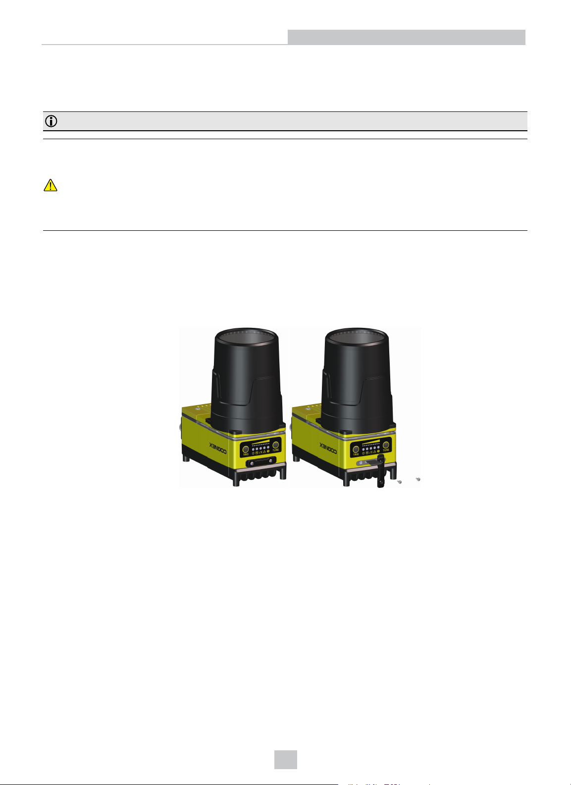
Replace the SD Card (Optional)
The vision system is equipped with a Micro SD card slot and an 8GB SD card is pre-installed for saving job and image
files. Complete the following steps to replace the pre-installed SD card.
Note: The vision system supports SD cards formatted with a FAT32 file system.
CAUTION:
l Hot-plugging the SD card is not supported and may damage the SD card and/or lead to unexpected
behavior.
l IP67 protection requires that all cables are properly attached (or the provided connector plug installed), the
IP67-rated lens cover is properly installed, and the Micro SD card cover is fastened in place.
l Observe ESD precautions when installing or removing an SD card or other accessories.
1. Remove power from the vision system.
2. Unscrew the screws in the Micro SD card cover and open the card slot.
3. Remove the existing SD card from the Micro SD card slot.
4. Insert the new SD card into the Micro SD card slot, ensuring the card is properly oriented.
5. Replace the SDcard cover, reinsert the screws and torque screws to 0.18 Nm (25 in-oz).
6. Restore power to the vision system.
16
Page 17
Specifications
Specifications
The following sections list general specifications for the vision system.
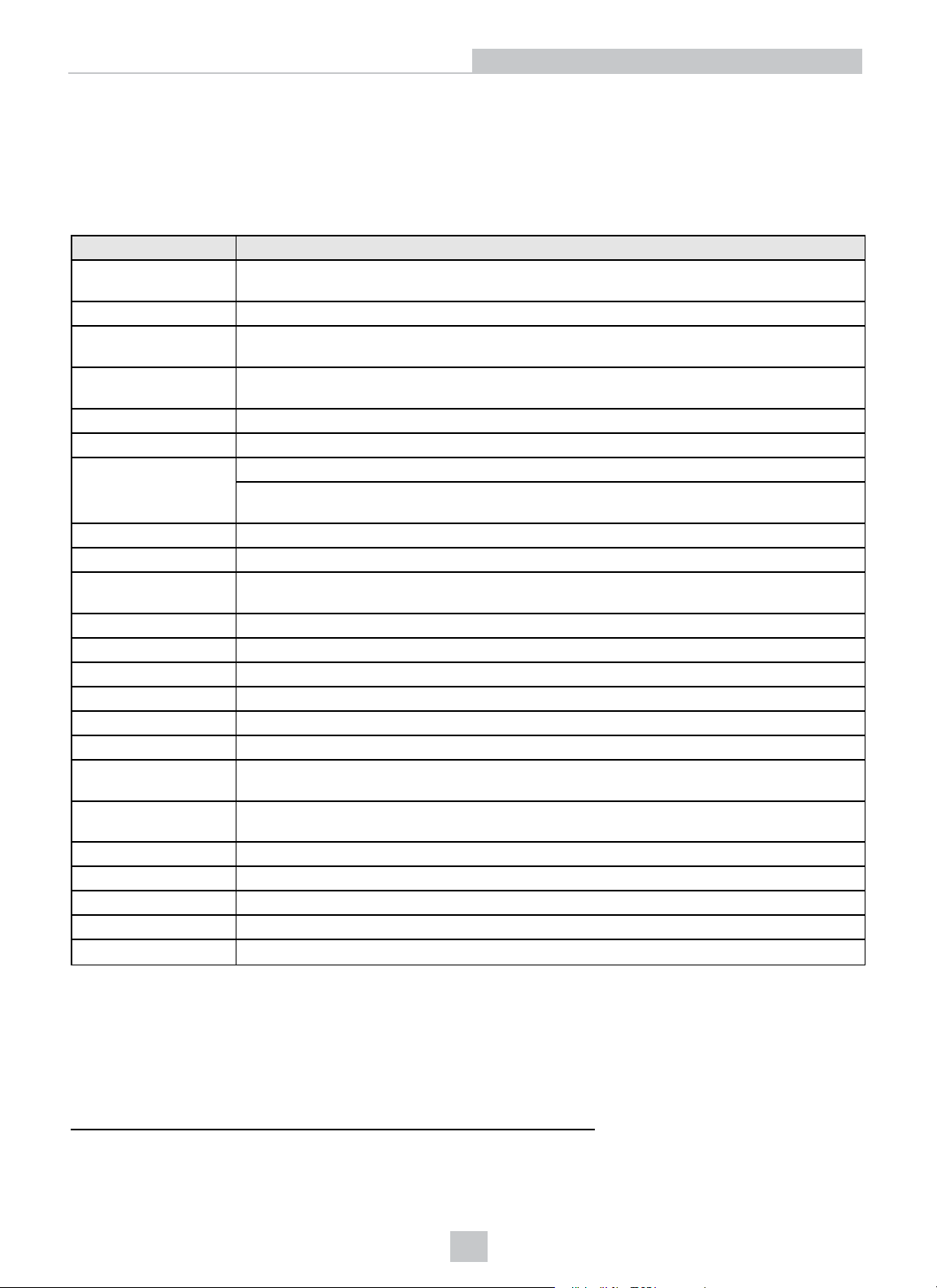
Vision System Specifications
Specifications 9902L
Minimum Firmware
Requirement
Job/Program Memory 7.2GB non-volatile flash memory; unlimited storage via remote network device.
Image Processing
Memory
SD Card Slot 1 Micro SD card slot with an 8GB SD card pre-installed for saving job and image files. The
Sensor Type 1-inch CMOS, line sensor
Sensor Properties 7µm x 7µm active area, 7µm x 7µm sq. pixels
Maximum Resolution
1
(pixels)
Acquisition Line Scan integration.
Bit Depth 256 grey levels (8 bits/pixel)
Lines Per Second
(LPS)
Lens Type C-Mount
Trigger 1 opto-isolated, acquisition trigger input. Remote software commands via Ethernet.
Discrete Inputs 1 general-purpose input when connected to the Breakout cable.
Discrete Outputs 2 high-speed outputs when connected to the Breakout cable.
Encoder Inputs 2 built-in, encoder inputs for use with a 24VDC signal.
Status LEDs SD Card Status, Pass/Fail LED and Indicator Ring, Network LED and Error LED.
Network
Communication
1588 Support
Serial Communication RS-232C when connected to the Breakout cable.
Power Consumption
Material Die-cast and extruded aluminum housing.
Finish Painted.
Mounting Four M4 threaded mounting holes on front and back of the vision system.
In-Sight version 5.6.1
512MB SDRAM
vision system supports SD cards formatted with a FAT32 file system.
2048 x 1; 2048 x 16384 (up to 16384 lines for a full resolution image).
1K Resolution (Low Light Mode): 1024 x 1; 1024 x 16384 (up to 16384 lines for a full
resolution image).
66K LPS
1 Ethernet port, 10/100/1000 BaseT with auto MDIX. IEEE 802.3 TCP/IP Protocol. Supports
DHCP, static and link-local IP address configuration.
Timestamp Resolution: 8ns
Synchronization Accuracy Through Transparent Clock: 5μs
24VDC ±10%, 1.5A maximum
1
The default resolutionis 2048 x 4096. The width and maximum image height can be adjusted in the Line Scan Settings dialog withinIn-Sight
Explorer. If the 1K Resolution (Low LightMode) checkbox is selected, the width isdecreased to 1024, providing increased light sensitivity.
Withinthe AcquireImage function,the Number of Lines parameter value can range from 1 to the Max Image Height.
17
Page 18
Specifications
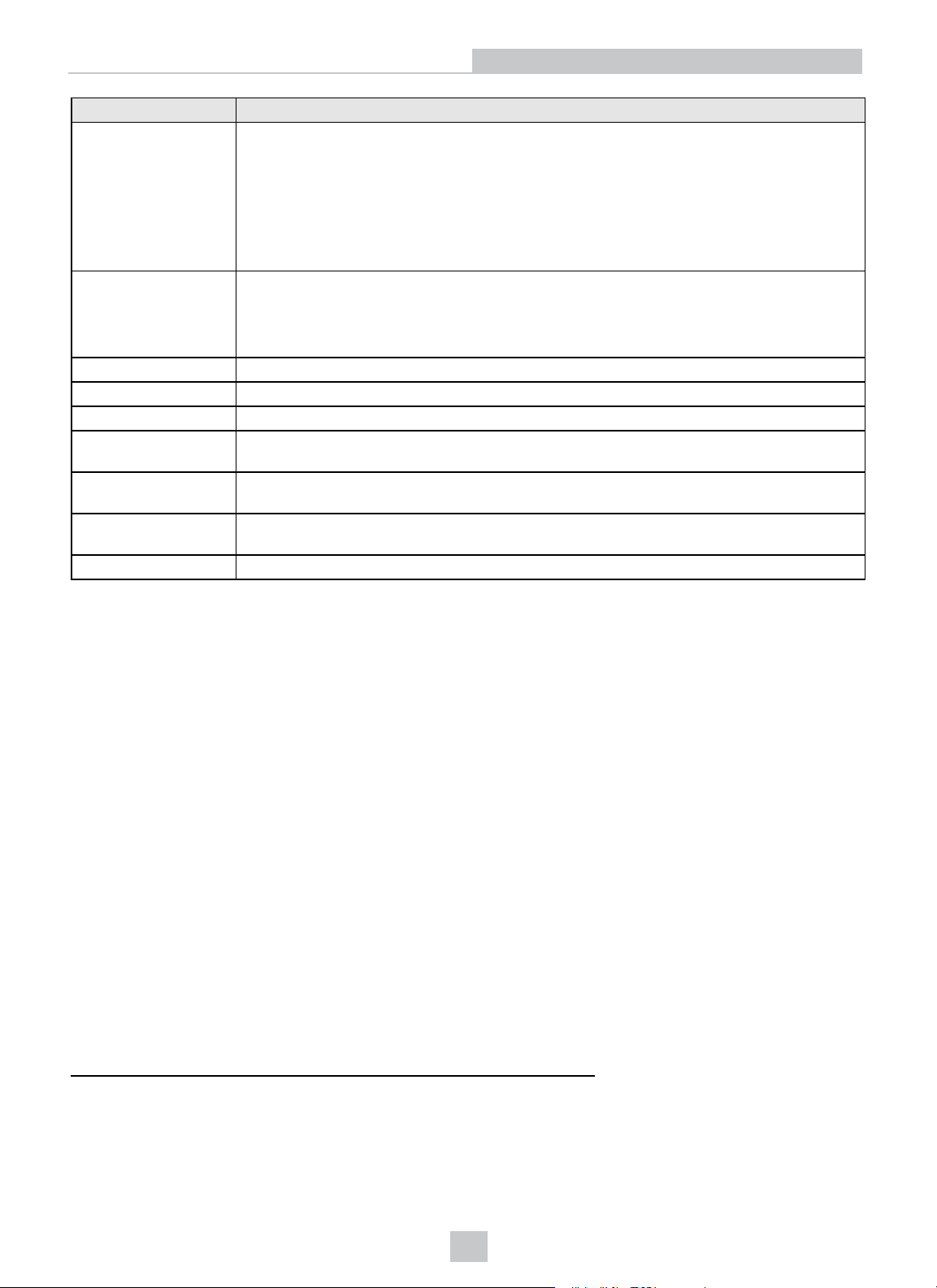
Specifications 9902L
Dimensions
Weight
Case Temperature
1
Storage Temperature -20°C to 80°C (-4°F to 176°F)
Humidity < 80% non-condensing
Protection IP67 with all cables properly attached (or the provided connector plug installed), the IP67-
Shock (Shipping and
Storage)
Vibration (Shipping
and Storage)
2
Regulations/Conformity CE, FCC, KCC, TÜV SÜD NRTL, EU RoHS, China RoHS
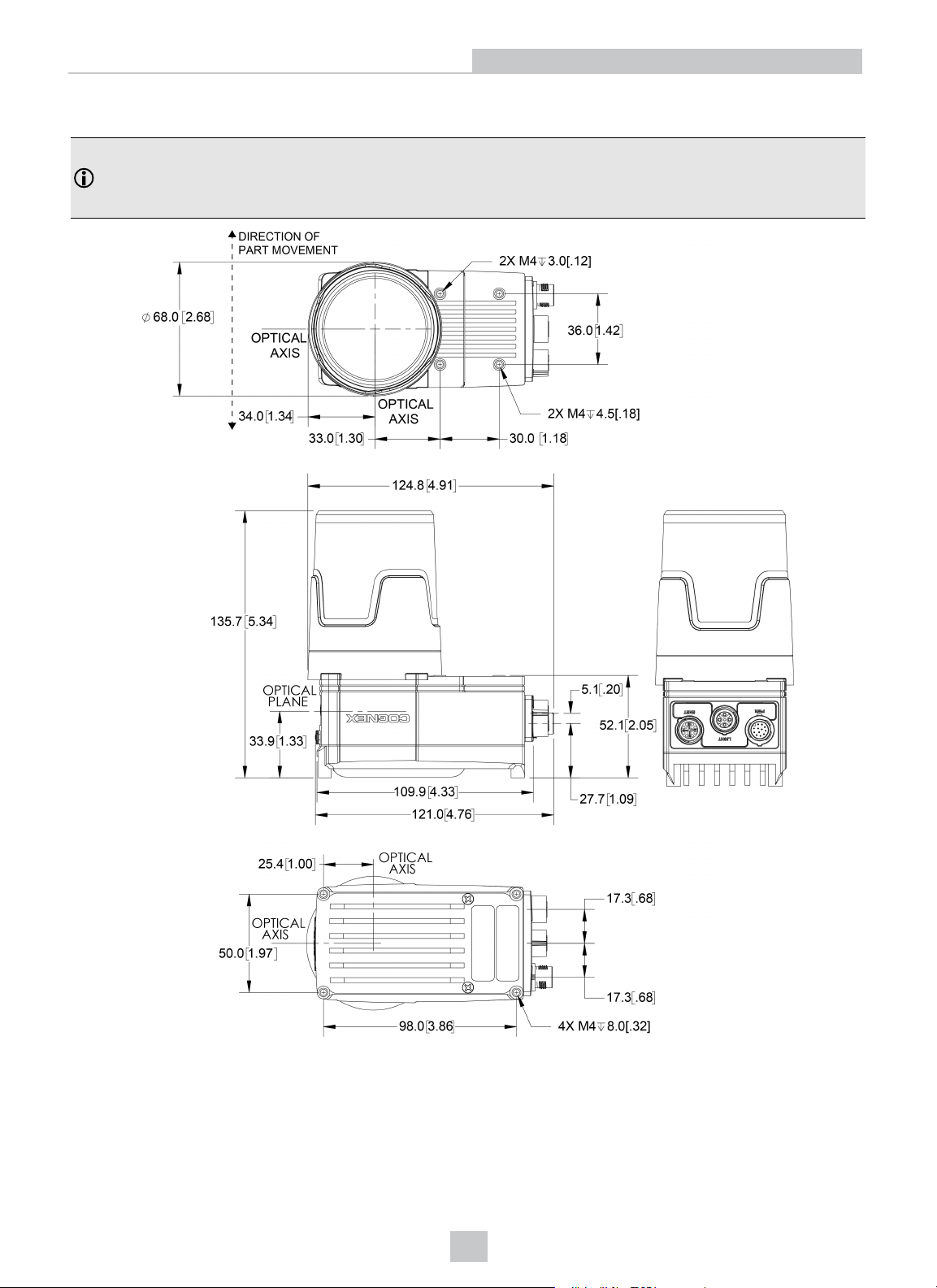
l 53.4mm (2.10in) x 60.5mm (2.38in) x 121.0mm (4.77in)
l 135.7 (5.34in) x 68.0mm (2.68in) x 121.0mm (4.77in) with C-Mount cover accessory
(COV-7000-CMNT-LG).
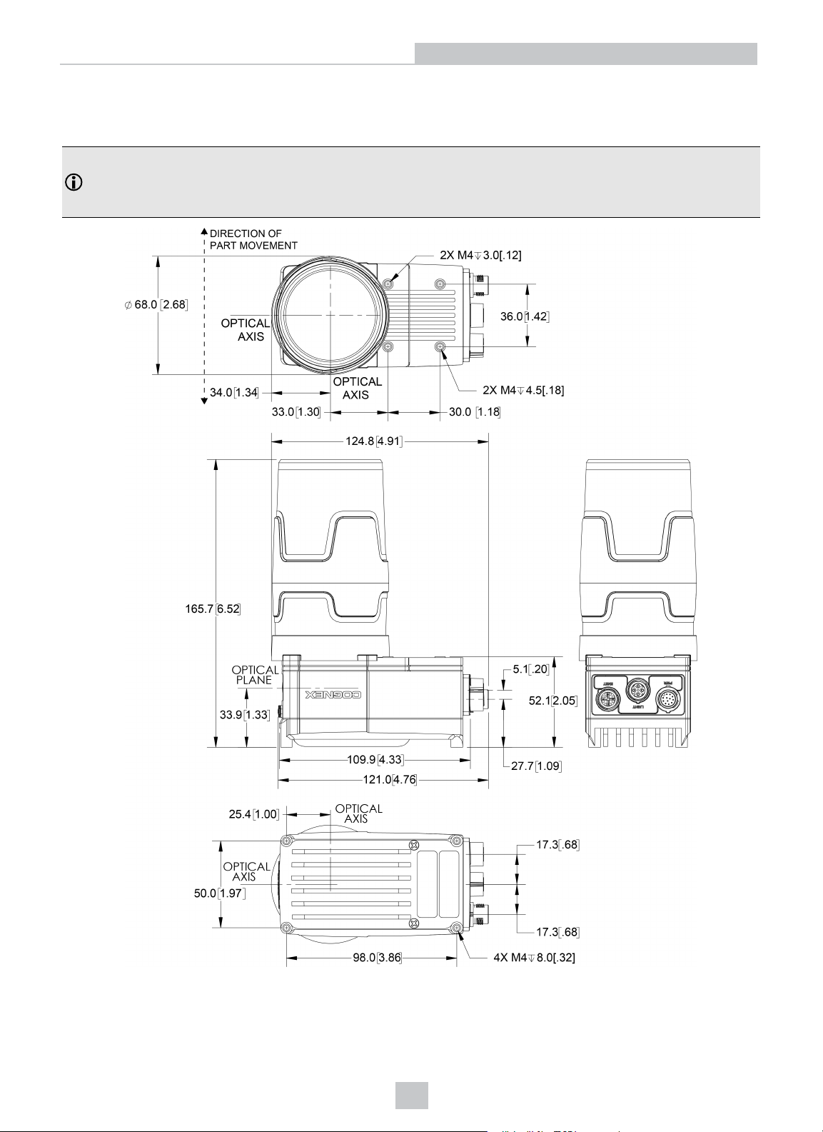
l 165.7 (6.52in) x 68.0mm (2.68in) x 121.0mm (4.77in) with C-Mount cover accessory
(COV-7000-CMNT-LG) and C-Mount cover extender accessory (COV-7000-CMNTLGX).
l Vision System with no accessories attached: 400 g (14.1 oz.)
l C-Mount cover accessory (COV-7000-CMNT-LG): 75.9 g (2.68 oz.)
l C-Mount cover extender accessory (COV-7000-CMNT-LGX): 25.0 g (0.88 oz.)
0°C to 50°C (32°F to 122°F).
rated cover properly installed and the Micro SD card cover fastened in place.
IEC 60068-2-27: 18 shocks (3 shocks in each polarity in each (X, Y, Z) axis) 80 Gs (800m/s2at
11ms, half-sinusoidal) with cables or cable plugs and a 150 gram or lighter lens attached.
IEC 60068-2-6: vibration test in each of the three main axis for 2 hours @ 10 Gs (10 to 500 Hz
at 100m/s2/ 15mm) with cables or cable plugs and a 150 gram or lighter lens attached.
1
To verify case temperature, use the EV GetSystemConfig(“Internal.Temperature”) Extended Native Mode command. When issued, it returns
the visionsysteminternal temperature indegreesCelsius,which is approximately3 to 5 degrees above the vision system case temperature.
For more information, see the In-Sight®Explorer Help file. A thermal scanner can also be used to determine the vision system case
temperature. Additionalcooling measures are required if the case temperature cannot be kept below 50°C. Examples of such measures
include: extra heat sinking and/or air movement.
2
Before you ship thisproduct or any machinery that contains it,remove lensesthat weigh more than 150 grams.
18
Page 19
Specifications
Acquisition Trigger Input
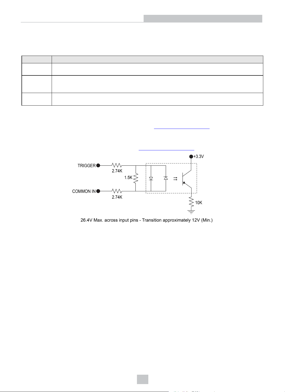
The vision system features one acquisition trigger input, which is optically isolated. The acquisition trigger input can be
configured to trigger from either an NPN (current sinking) or PNP (current sourcing) device.
Specification Description
Voltage
Current
(Typical)
Delay
l To trigger from an NPN type photoelectric sensor or PLC output, connect COMMON IN to +24VDC and connect
TRIGGER to the output of the photoelectric sensor. When the output turns ON, it pulls TRIGGER down to 0VDC,
turning the opto-coupler ON. For more information, refer to Breakout Cable on page25.
l To trigger from a PNP photoelectric sensor or PLC output, connect TRIGGER to the output of the photoelectric
sensor and connect COMMON IN to 0VDC. When the output turns ON, it pulls TRIGGER up to +24VDC, turning
the opto-coupler ON. For more information, refer to Breakout Cable on page25.
ON: 15 to 28V DC (24DC nominal)
OFF: 0 to 5VDC (11.5VDC nominal threshold)
ON: 2.6mA to 4.9mA from 15 to 28V input
OFF: < 830µA for < 5VDC input
Resistance:~6 Kohms
1 line + 5µs is the maximum latency between the leading edge of the trigger and the start of acquisition.
The line period varies depending on acquisition settings.
Input pulse should be a minimum of 1ms wide.
19
Page 20
Specifications
Encoder Inputs
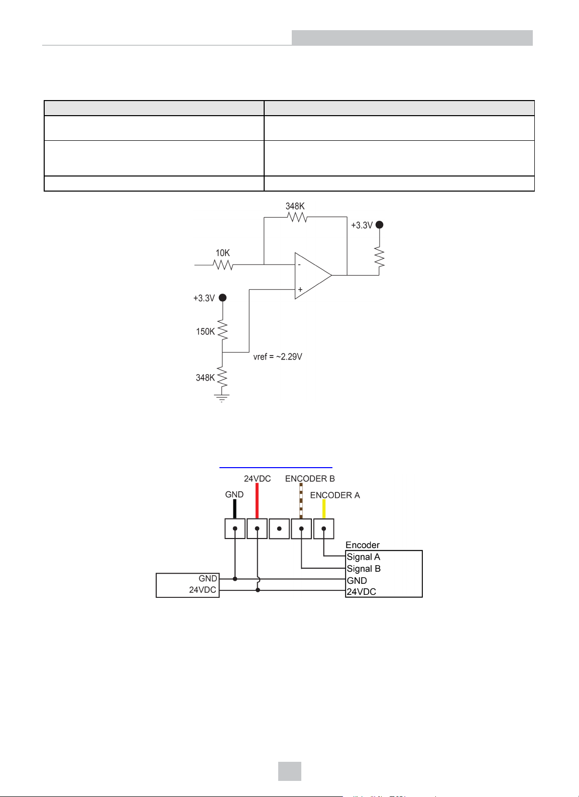
The Breakout cable can be used for communication between the vision system and a single or quadrature encoder.
Specification Description
Voltage
Current
Maximum Encoder Frequency 96KHz (assuming a 50/50 duty cycle)
ON: 5 to 24VDC
OFF: <2VDC
ON: <1000µA
OFF: 0µA
Resistance: ~350 kOhms
Encoder Input Wiring
For single encoders, the ENCODER A pin must be used. For quadrature encoders, the ENCODER A or ENCODER B pin
can be used. For more information, refer to Breakout Cable on page25.
20
Page 21
Specifications
General-Purpose Input
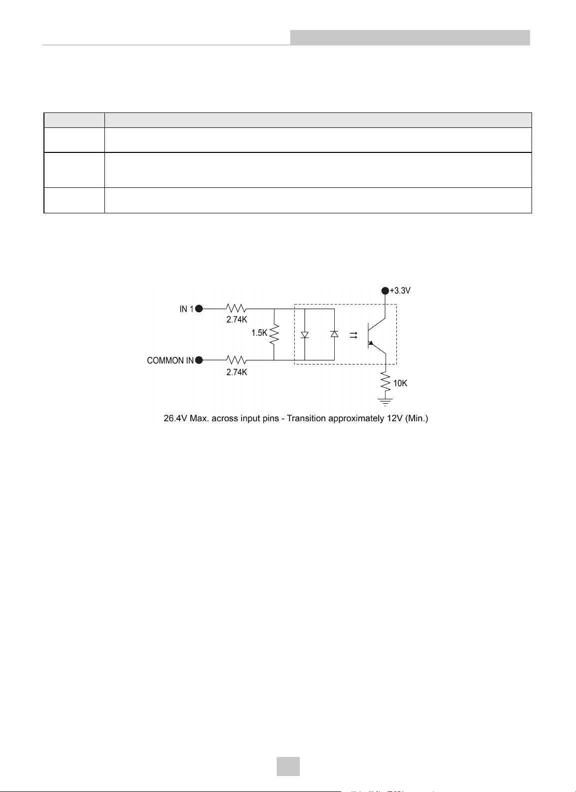
The vision system features one built-in general-purpose input, which is optically isolated. The input can be configured as
either NPN (current sinking) or PNP (current sourcing) lines.
Specification Description
Voltage
Current
(Typical)
Delay 1.11ms maximum latency between leading edge of trigger and start of acquisition. Input pulse should be
l For NPN lines, connect COMMONIN to +24VDC and connect IN 1 to the output of the photoelectric sensor or
PLC. When the output turns ON, it pulls IN 1 down to 0VDC, turning the opto-coupler ON.
l For PNP lines, connect IN 1 to the output of the detector and connect COMMONIN to 0VDC. When the output
turns ON, it pulls IN 1 up to +24VDC, turning the opto-coupler ON.
ON: 15 to 28V DC (24DC nominal)
OFF: 0 to 5VDC (11.5VDC nominal threshold)
ON: 2.6mA to 4.9mA from 15 to 28V input
OFF: < 830µA for < 5VDC input
Resistance:~6 Kohms
minimum of 1ms wide.
21
Page 22
Specifications
High-Speed Outputs
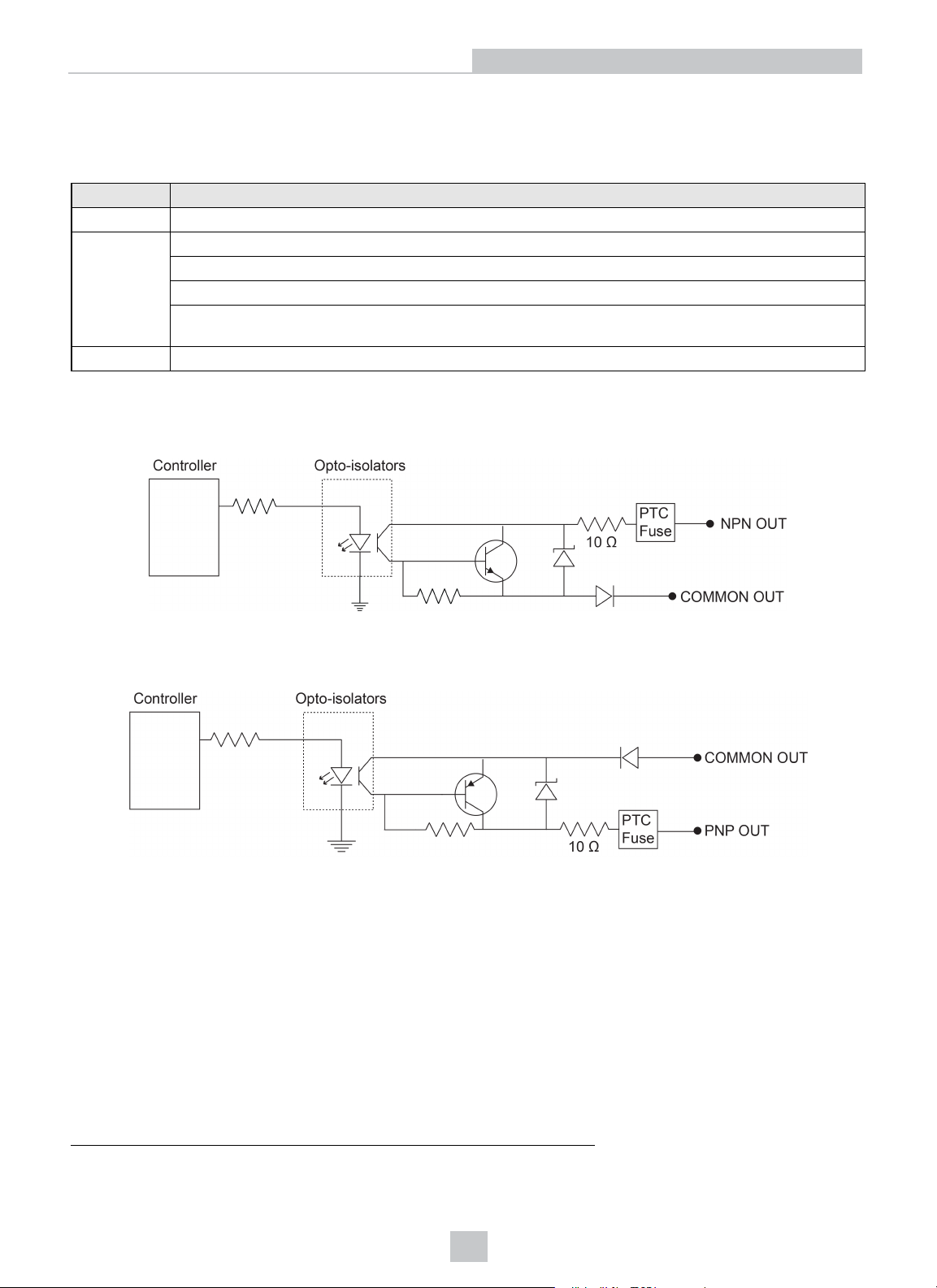
The vision system features two built-in, high-speed outputs, which are optically isolated. The high-speed outputs can be
used as either NPN (current sinking) or PNP (current sourcing) lines.
Specification Description
Voltage 26.4VDC maximum through external load
Current 50mA maximum sink or source current
OFF state leakage current 100µA
External load resistance 470 Ohms to 10K Ohms
Each line rated at a maximum 50mA, protected against over-current, short circuits and transients from
switching inductive loads. High current inductive loads require an external protection diode.
1
Delay
For NPN lines, the external load should be connected between the output and the positive supply voltage (<26.4VDC).
The output pulls down to less than 3VDC when ON, which causes current to flow through the load. When the output is
OFF, no current flows through the load.
25μs (maximum due to opto-isolators turning ON).
For PNP lines, the external load should be connected between the output and the negative supply voltage (0VDC).
When connected to a 24VDC power supply, the output pulls up greater than 21VDC when ON, and current flows through
the load. When the output is OFF, no current flows through the load.
1
Delay when opto-isolators turn OFF depends on the load to which the output is connected. With a 470 Ohm load, the maximum delay will be
200μs.
22
Page 23
Specifications
High-Speed Output Wiring
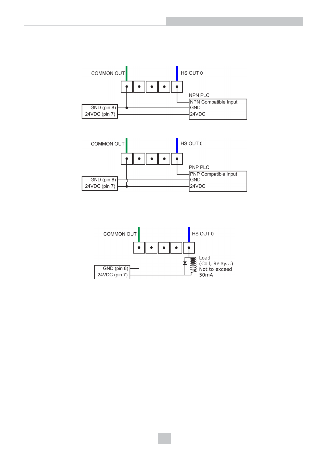
To connect to an NPN-compatible PLC input, connect one of the vision system's high-speed outputs directly to the PLC
input. When enabled, the output pulls the PLC input down to less than 3VDC.
To connect to a PNP-compatible PLC input, connect one of the vision system's high-speed outputs directly to the PLC
input. When enabled, the output pulls the PLC input up to greater than 21VDC.
To connect the high-speed outputs to a relay, LED or similar load, connect the negative side of the load to the output and
the positive side to +24VDC. When the output switches on, the negative side of the load is pulled down to less than
3VDC, and 24VDC appears across the load. Use a protection diode for a large inductive load, with the anode connected
to the output and the cathode connected to +24VDC.
23
Page 24
Ethernet Cable
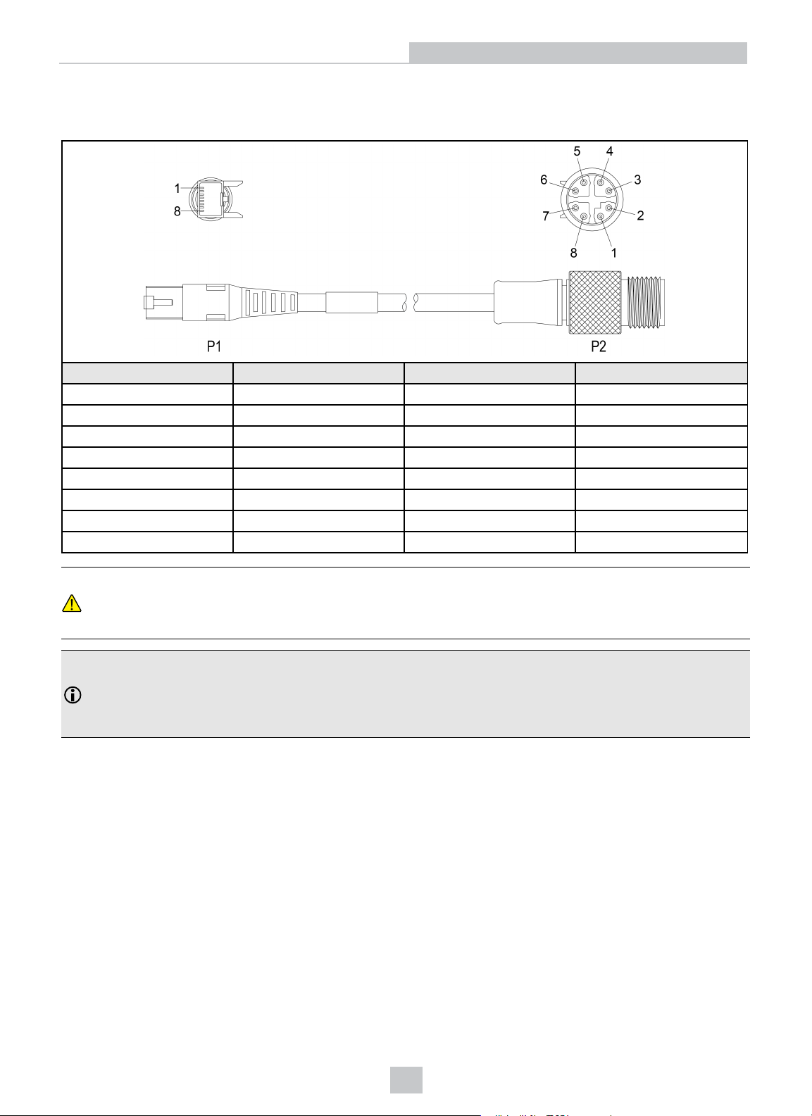
The Ethernet cable provides Ethernet connectivity to the vision system.
P1 Pin Number Wire Color Signal Name P2 Pin Number
1 White/Orange TxRx A + 1
2 Orange TxRx A - 2
3 White/Green TxRx B + 3
4 Blue TxRx C + 8
5 White/Blue TxRx C - 7
6 Green TxRx B - 4
7 White/Brown TxRx D + 5
8 Brown TxRx D - 6
Specifications
CAUTION: The Ethernet cable shield must be grounded at the far end. Whatever this cable is plugged into
(typically a switch or router) should have a grounded Ethernet connector. A digital voltmeter should be used to
validate the grounding. If the far end device is not grounded, a ground wire should be added in compliance with
local electrical codes.
Note:
l Cables are sold separately.
l The wiring for this cable follows standard industrial Ethernet M12 specifications. This differs from the 568B
standard.
24
Page 25
Breakout Cable
Specifications
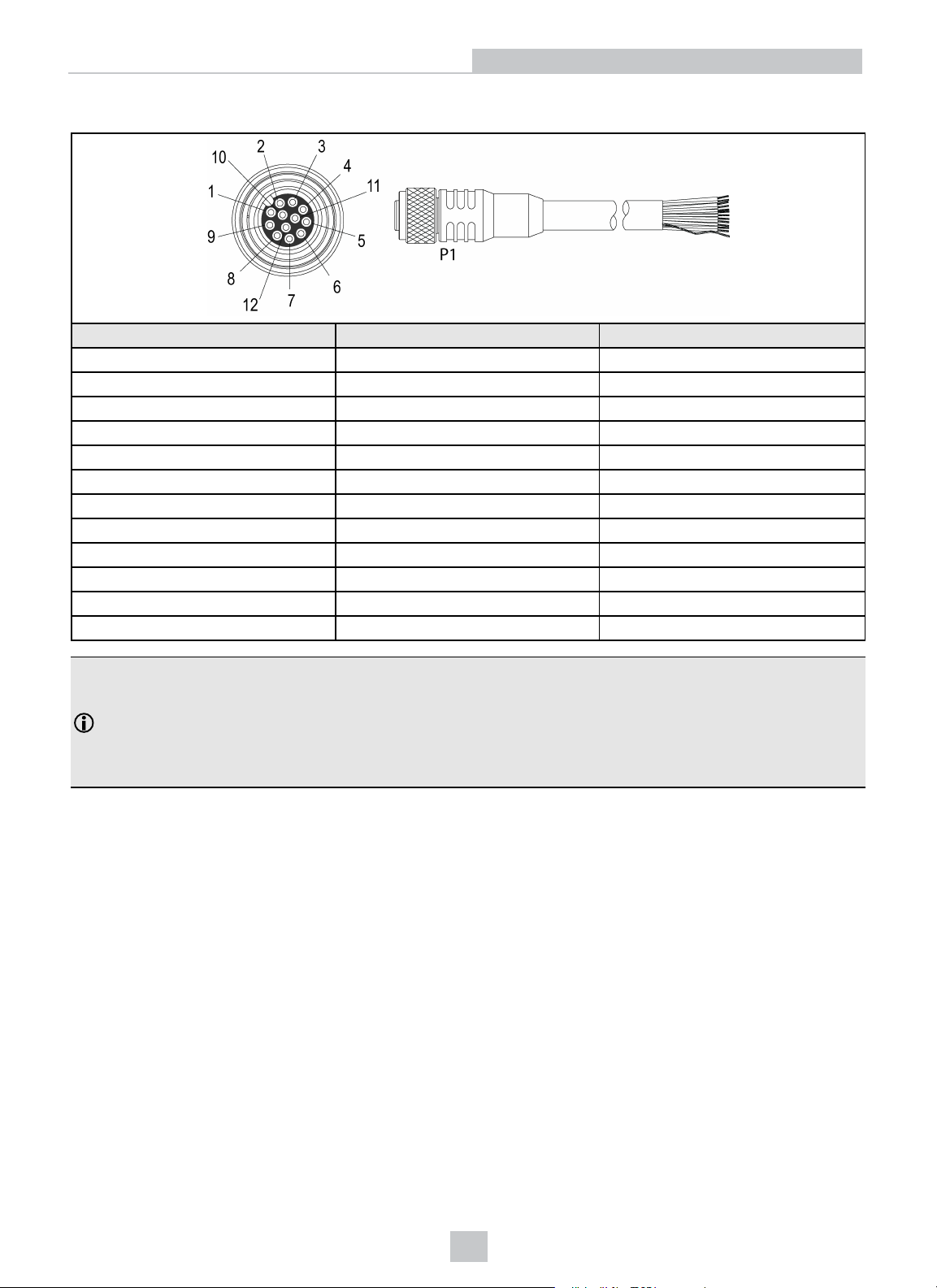
Pin# Signal Name
1 ENCODER A INPUT Yellow
2 RS-232 TRANSMIT White/Yellow
3 RS-232 RECEIVE Brown
4 ENCODER B INPUT White/Brown
5 IN 1 Violet
6 COMMON IN White/Violet
7 +24VDC Red
8 GND Black
9 COMMON OUT Green
10 TRIGGER Orange
11 HS OUT 0 Blue
12 HS OUT 1 Grey
Note:
l Cables are sold separately.
l Exposed wires can be cut short or wire ends trimmed, and the wires tied back using a tie made of non-
conductive material. Keep all bare wires separated from the +24VDC wire.
l Perform wiring or adjustments to I/O devices when the vision system is not receiving power.
Wire Color
25
Page 26
Dimensions
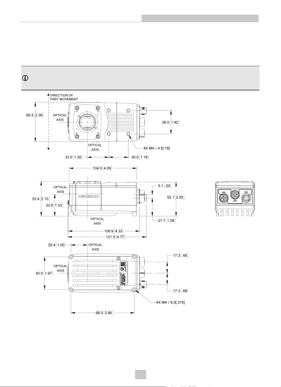
The following sections list dimensions of the vision system and optional accessories.
Vision System Dimensions
Note:
l All dimensions are in millimeters [inches] and are for reference purposes only.
l All specifications are for reference purpose only and may be changed without notice.
Specifications
26
Page 27
Vision System with Cover (COV-7000-CMNT-LG)
Note:
l All dimensions are in millimeters [inches] and are for reference purposes only.
l All specifications are for reference purpose only and may be changed without notice.
Specifications
27
Page 28
Specifications
Vision System with Cover (COV-7000-CMNT-LG) and Extender (COV-7000CMNT-LGX)
Note:
l All dimensions are in millimeters [inches] and are for reference purposes only.
l All specifications are for reference purpose only and may be changed without notice.
28
Page 29
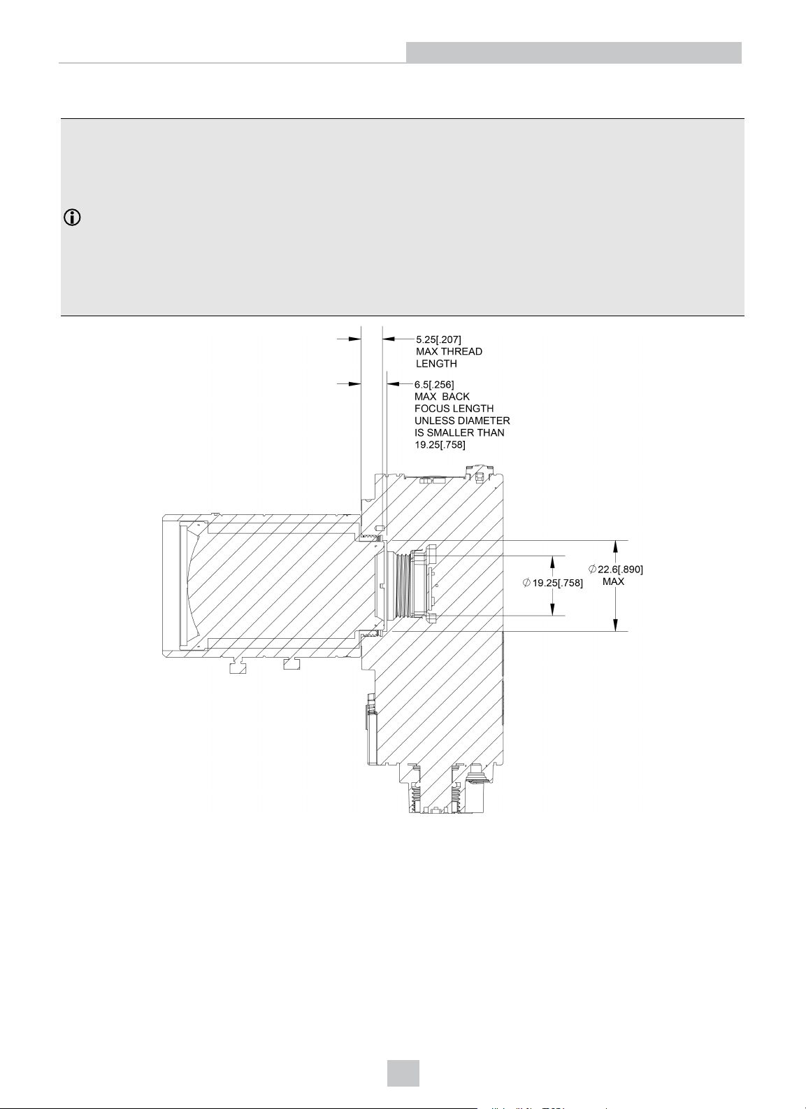
C-Mount Lens Clearance Dimensions
Note:
l A C-Mount lens has the following restrictions:
l Maximum thread length is 5.25mm.
l The C-Mount lens threads and body cannot protrude more than 6.5mm in length into the vision
system when screwed in, unless the diameter of the back lens is smaller than 19.25mm. If the CMount lens threads and body protrude more than 6.5mm, you can add a spacer between the lens
and vision system. However, the spacer decreases the working distance.
l All dimensions are in millimeters [inches] and are for reference purposes only.
l All specifications are for reference purpose only and may be changed without notice.
Specifications
29
Page 30
Cleaning and Maintenance
Cleaning and Maintenance
Clean the Housing
To clean the outside of the vision system housing, use a small amount of mild detergent cleaner or isopropyl alcohol on
a cleaning cloth. Do not pour the cleaner directly onto the vision system housing.
CAUTION: Do not attempt to clean any In-Sight product with harsh or corrosive solvents, including lye, methyl ethyl
ketone (MEK) or gasoline.
Clean the Image Sensor Window
To remove dust from the outside of the image sensor window, use a pressurized air duster. The air must be free of oil,
moisture or other contaminants that could remain on the glass and possibly degrade the image. Do not touch the glass
window. If oil/smudges still remain, clean the window with a cotton bud using alcohol (ethyl, methyl or isopropyl). Do not
pour the alcohol directly on the window.
Clean the Cover
To remove dust from the lens cover, use a pressurized air duster. The air must be free of oil, moisture or other
contaminants that could remain on the lens cover. To clean the plastic window of the lens cover, use a small amount of
isopropyl alcohol on a cleaning cloth. Do not scratch the plastic window. Do not pour the alcohol directly on the plastic
window.
30
Page 31

 Loading...