

Page 1
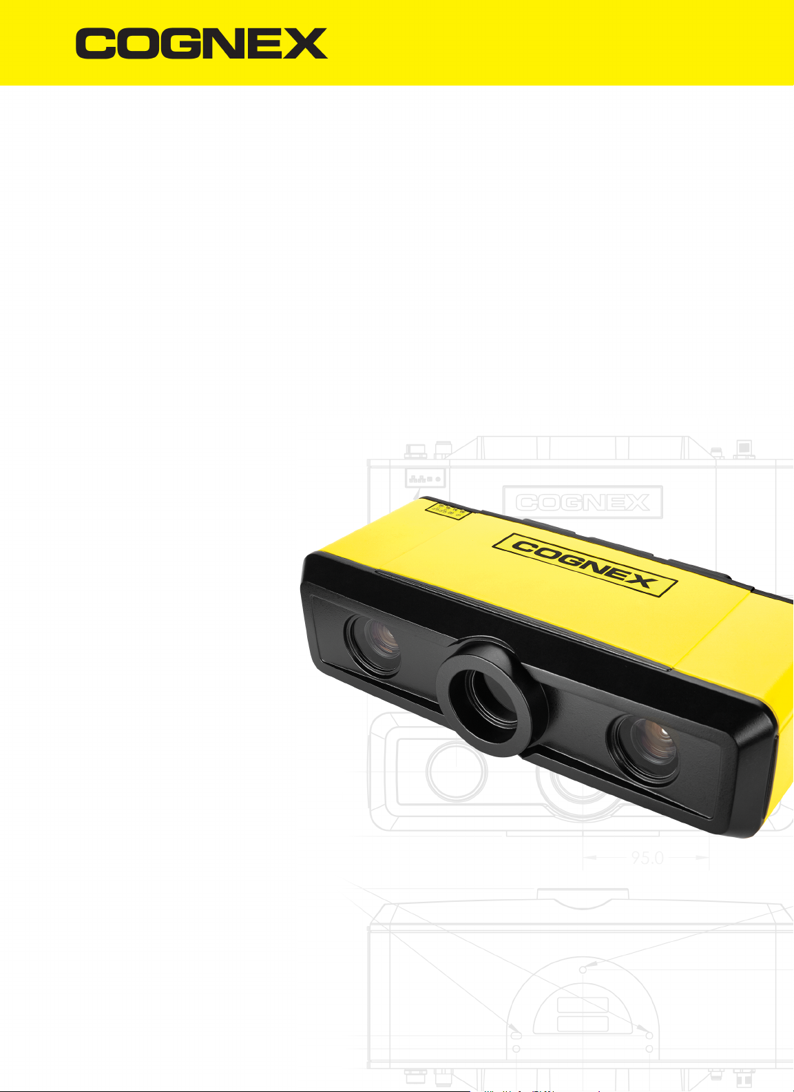
3D-A5000™ Series Sensors
Hardware Reference
2019 January 21
Revision:9.5.0.7
Page 2
Table of Contents
Table of Contents
Table of Contents 2
Legal Notices 3
Symbols 4
Cognex 3D-A5000 Sensors 5
PC Requirements 6
Supported Sensors 6
Operating Conditions 8
Hardware Installation 9
Precautions 9
Deploy the PC and the 3D Sensor 10
LED Indicators 10
Caution Labels 11
I/O Cable 13
HardwareTriggers 13
Discrete Outputs 14
Cleaning and Handling 16
Regulations/Conformity:3D-A5000 Sensors 17
For European Community Users 18
2
Page 3
Legal Notices
Legal Notices
The software described in this document is furnished under license, and may be used or copied only in accordance with
the terms of such license and with the inclusion of the copyright notice shown on this page. Neither the software, this
document, nor any copies thereof may be provided to, or otherwise made available to, anyone other than the licensee.
Title to, and ownership of, this software remains with Cognex Corporation or its licensor. Cognex Corporation assumes
no responsibility for the use or reliability of its software on equipment that is not supplied by Cognex Corporation.
Cognex Corporation makes no warranties, either express or implied, regarding the described software, its
merchantability, non-infringement or its fitness for any particular purpose.
The information in this document is subject to change without notice and should not be construed as a commitment by
Cognex Corporation. Cognex Corporation is not responsible for any errors that may be present in either this document or
the associated software.
Companies, names, and data used in examples herein are fictitious unless otherwise noted. No part of this document
may be reproduced or transmitted in any form or by any means, electronic or mechanical, for any purpose, nor
transferred to any other media or language without the written permission of Cognex Corporation.
Copyright © 2018. Cognex Corporation. All Rights Reserved.
Portions of the hardware and software provided by Cognex may be covered by one or more U.S. and foreign patents, as
well as pending U.S. and foreign patents listed on the Cognex web site at: cognex.com/patents.
The following are registered trademarks of Cognex Corporation:
Cognex, 2DMAX, Advantage, AlignPlus, Assemblyplus, CheckitwithChecker, Checker, CognexVisionforIndustry,
CognexVSOC, CVL, DataMan, DisplayInspect, DVT, EasyBuilder, Hotbars, IDMax, In-Sight, LaserKiller, MVS-8000,
OmniView, PatFind, PatFlex, PatInspect, PatMax, PatQuick, SensorView, SmartView, SmartAdvisor, SmartLearn,
UltraLight, VisionSolutions, VisionPro, VisionView
The following are trademarks of Cognex Corporation:
The Cognex logo, 1DMax, 3D-Locate, 3DMax, BGAII, CheckPoint, CognexVSoC, CVC-1000, FFD, iLearn, In-Sight
(design insignia with cross-hairs), In-Sight2000, InspectEdge, Inspection Designer, MVS, NotchMax, OCRMax,
PatMaxRedLine, ProofRead, SmartSync, ProfilePlus, SmartDisplay, SmartSystem, SMD4, VisiFlex, Xpand
Portions copyright © Microsoft Corporation. All rights reserved.
Portions copyright © MadCap Software, Inc. All rights reserved.
Other product and company trademarks identified herein are the trademarks of their respective owners.
3
Page 4
Symbols
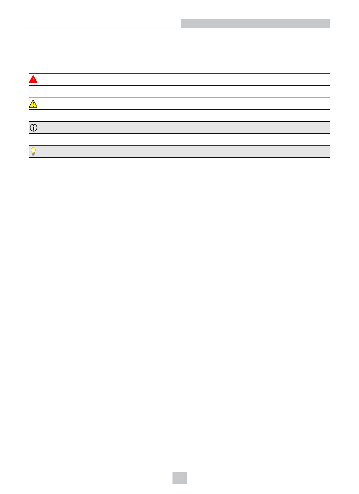
The following symbols indicate safety precautions and supplemental information:
WARNING: This symbol indicates a hazard that could cause death, serious personal injury or electrical shock.
CAUTION: This symbol indicates a hazard that could result in property damage.
Note: This symbol indicates additional information about a subject.
Tip: This symbol indicates suggestions and shortcuts that might not otherwise be apparent.
Symbols
4
Page 5
Cognex 3D-A5000 Sensors
Cognex 3D-A5000 Sensors
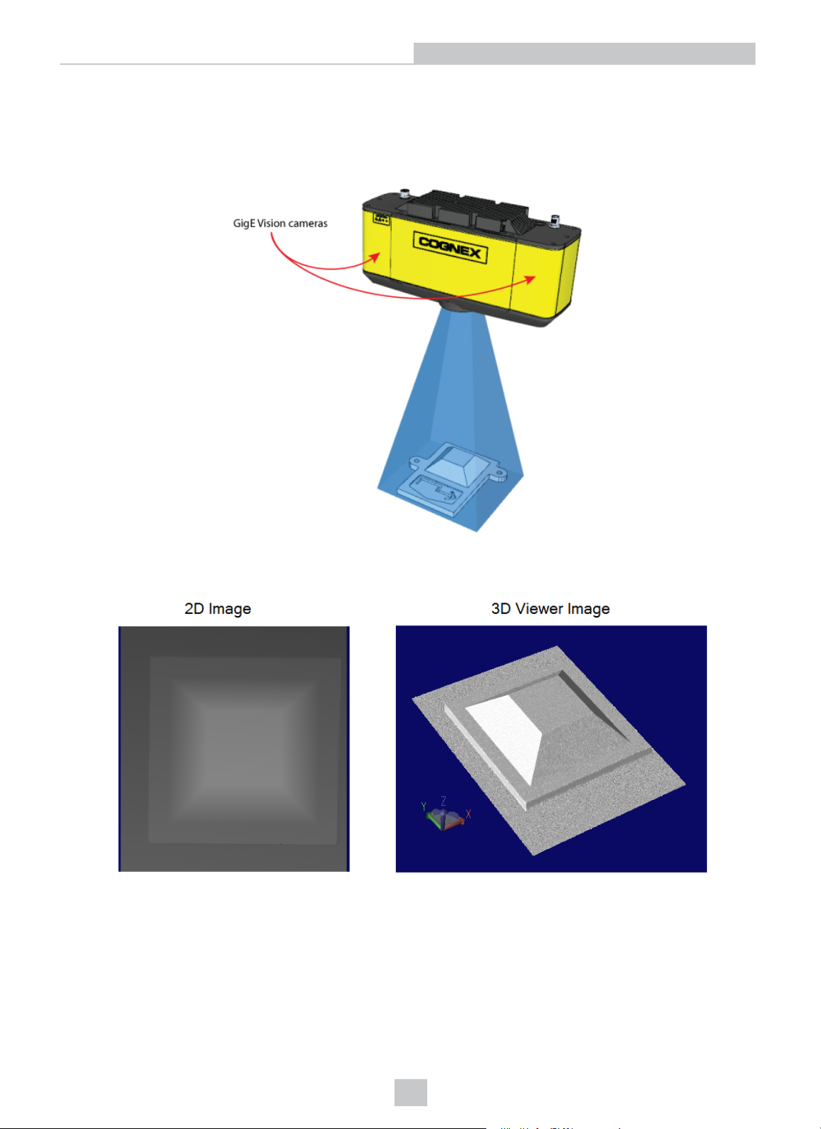
Cognex 3D-A5000 sensors combine structured light projection and GigE Vision cameras to generate information about
three-dimensional objects. The sensor projects a pattern on an area within the field of view of two enclosed cameras:
Cognex software builds a 3D data structure representing the object from geometrically distorted images taken from the
two cameras, which can then be viewed as a static 2D image or dynamically through a 3D viewing option:
Once you have the 3D data, VisionPro supports a variety of 3D vision tools for performing tasks such as:
l Finding the 3D pose of a trained 3D model
l Generating height or volume calculations
l Analyzing a cross-section of the object
See your installed VisionPro documentation for details.
5
Page 6
Cognex 3D-A5000 Sensors
PC Requirements
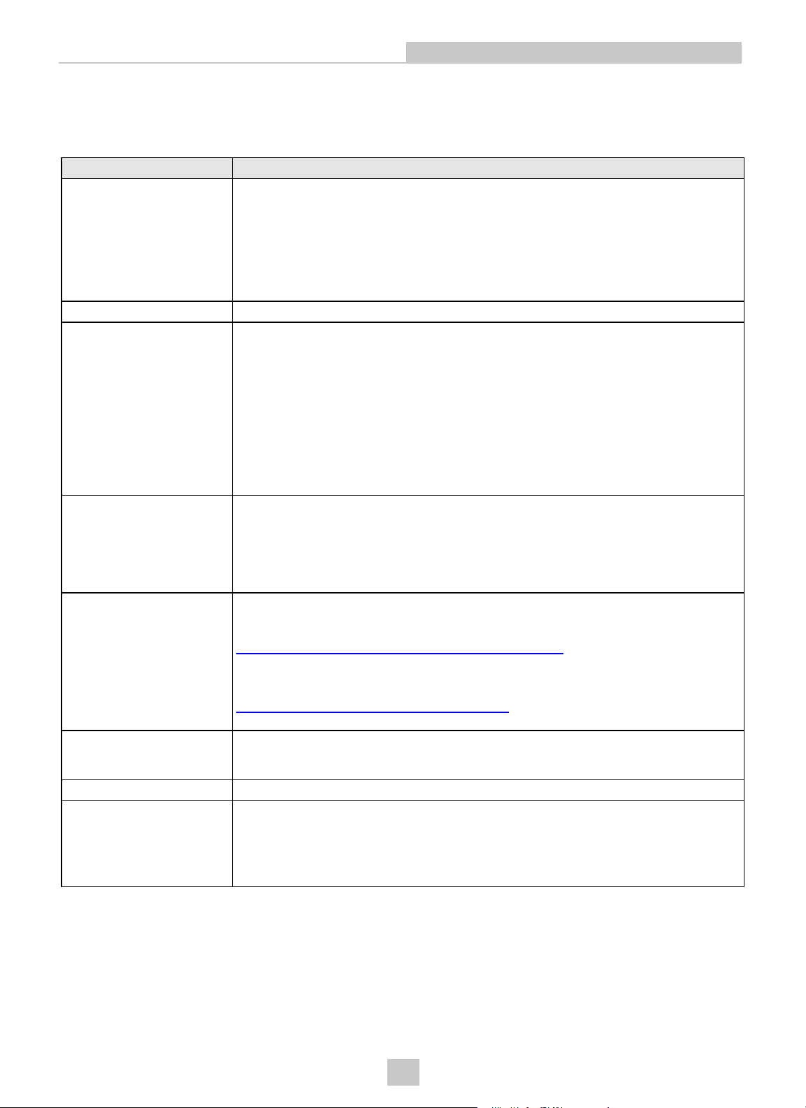
Any PC you use with a 3D-A5000 sensor must meet certain minimum requirements. Cognex also makes
recommendations for some components.
Components Requirement
CPU
Operating System Windows 10 Pro 64-bit
GPU (mandatory)
Minimum:
l 4th generation Intel® Core™ i5 Processor with 4 cores
Recommended:
l 8th generation Intel Core i7 Processor with four physical cores (8 logical cores)
l Intel Xeon E5 Processor with six physical cores (12 logical cores)
Minimum:
l NVIDIA GeForce GTX 1070
Recommended:
l NVIDIA GeForce GTX 1080
Cognex also supports:
NVIDIA Graphics Driver
10 Gigabit Ethernet Adapter
RAM
Ethernet Cable
Power Supply
l NVIDIA GeForce GTX 1070 Ti
l NVIDIA GeForce GTX 1080 Ti
Minimum:
l Version 387
Recommended:
l Version 396 or later
Recommended:
Chelsio T520-BT
https://www.chelsio.com/nic/unified-wire-adapters/t520-bt/
Refer to the Chelsio documentation for correct installation procedures
Download the latest driver software for the Chelsio T520-BT:
https://service.chelsio.com/downloads/Microsoft/
Recommended Package Type:exe
Minimum:8GB
Recommended:16GB
Recommended:Cat6a
Required power supply depends on all system components. For typical setups (no
additional hardware components [single GPU, single CPU]):
l 600W power supply for GTX 1070 and GTX 1070 Ti
l 700W power supply for GTX 1080 and GT 1080 Ti
Supported Sensors
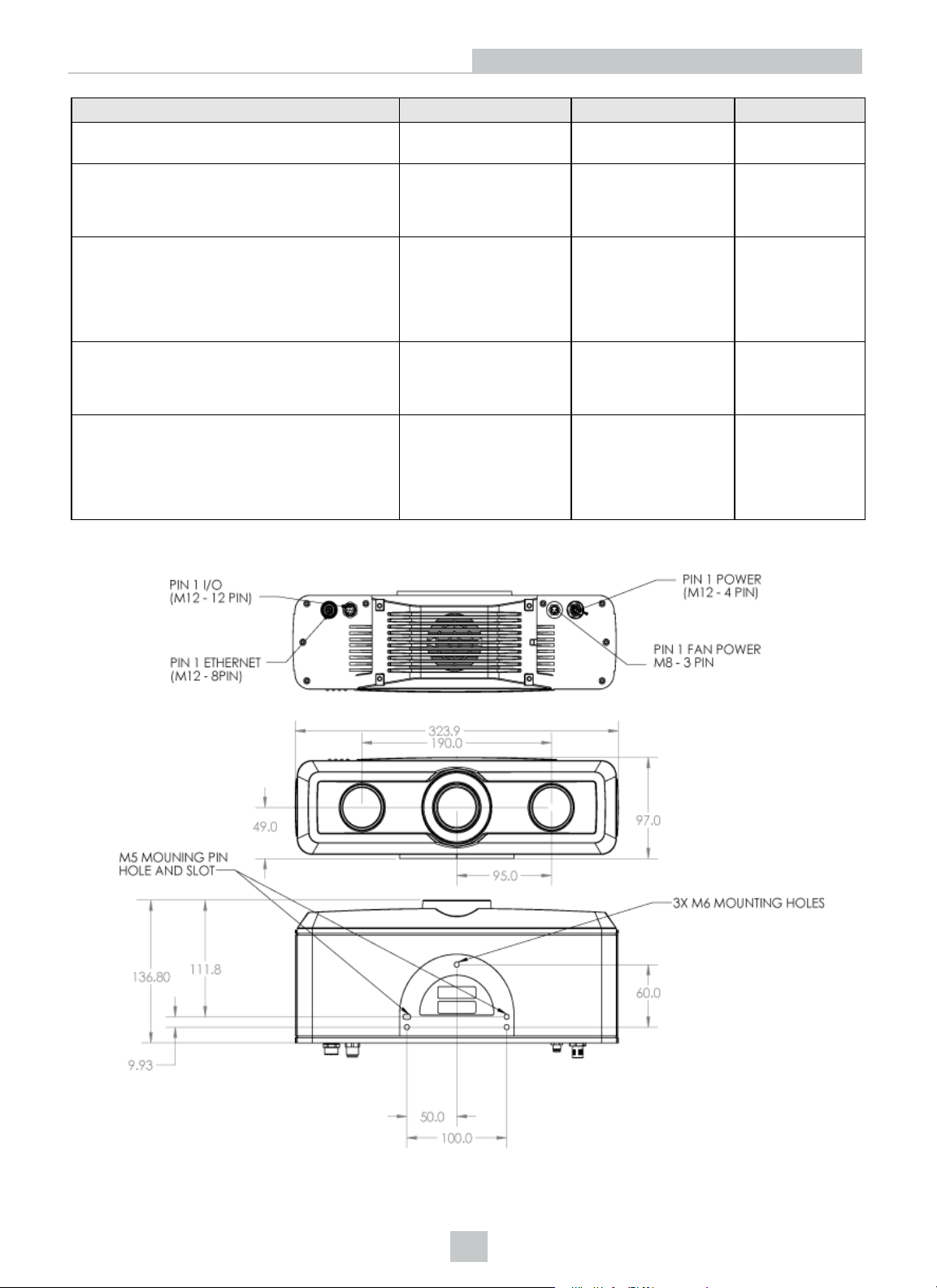
Refer to the following table for details on the 3D-A5000 sensors supported by this VisionPro release:
6
Page 7
Cognex 3D-A5000 Sensors
Specification 3D-A5005 3D-A5030 3D-A5060
Resolution X, Y = 42 - 44 µm X, Y = 195 - 199 µm X, Y = 361 - 454
µm
Clearance Distance (mm)
The minimum distance required before the
sensor will detect 3D features.
Near Field of View (mm x mm)
The size of the area closest to the sensor where
3D features can be detected. Features above
the Near Field of View will not be captured by
the sensor.
Measurement Range (mm)
The total distance in which the sensor can
detect 3D features.
Far Field of View (mm x mm)
The size of the area farthest from the sensor
where 3D features can be detected. Features
below the Far Field of View will not be captured
by the sensor.
300 1465 1400
60 x 44 280 x 210 520 x 390
12 80 400
65 x 46 285 x 215 645 x 490
Refer to the following diagram for physical dimensions of the 3D-A5000 sensor:
7
Page 8
Cognex 3D-A5000 Sensors
Operating Conditions
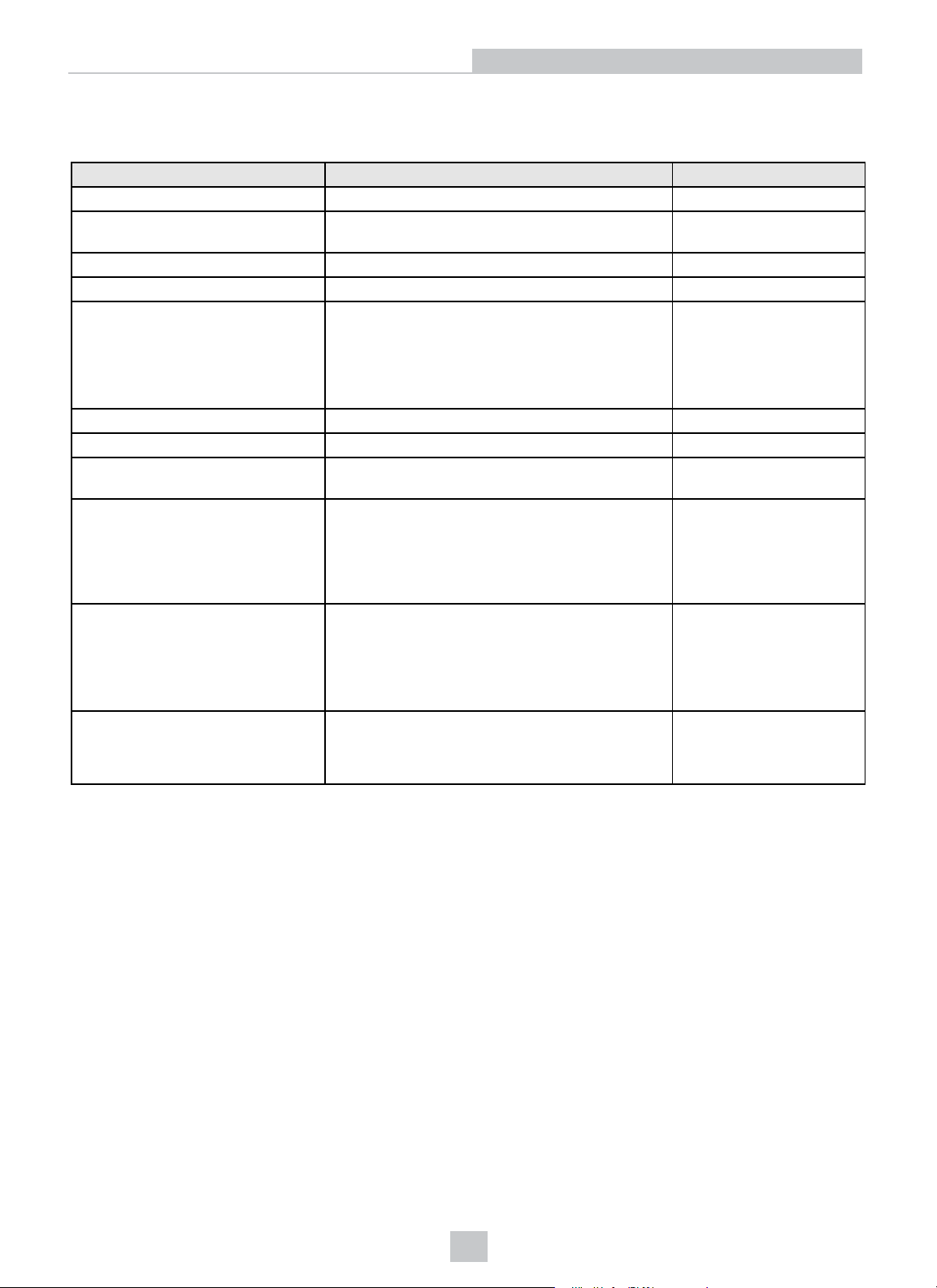
Be aware of the general operating conditions of a 3D-A5000 sensor:
Specification Description Notes
IP Rating IP65
Operating temperature range 0 - 40°C Accurate measurements in
trigger mode:22°C +/- 5°C
Storage Temperature -10°C to 60°C
Ambient Temperature 0°C to 40°C
Power Supply Requirements
Operating Current
Maximum Humidity 85% non-condensing (maximum)
Shock (unit in a shipping padded
container)
Vibration
+24VDC +/- 10%
144W (6.0A)with illumination on at maximum
intensity
15W (0.6A)with illumination off
Up to 6.0A depending on operation-mode
3 Axis, 50 Gs (11ms half-sine pulse)
Non-operating (unit does not acquire images while
under vibration): 3 Axis, 8 Gs (10-500 Hz for 30
minutes)
Trigger Inputs
Discrete Outputs
Accurate Measurements: 3 Axis, 2G RMS Sine
Sweep 10-200 Hz continuous
1 opto-isolated acquisition trigger input
4V...24V (High); 0.0V...0.5V (Low)
Configurable as current sink (NPN) or current
source (PNP)
3 opto-isolated outputs
Configurable as current sink (NPN) or current
source (PNP)
8
Page 9
Hardware Installation
Hardware Installation
Cognex ships your 3D-A5000 sensor with a power supply and cables for the GigE Vision cameras and I/O connections.
See the section PC Requirements on page6 for the minimum PC requirements to use with your 3D-A5000 sensor.
Be aware you need the following accessories to complete the installation of your PC and 3D-A5000 series sensor:
l A 1024 x 768 display at 96 DPI
l Any network cables to connect your PC to your corporate network
l A VisionPro security key.
The security key provides a security mechanism to ensure that the Cognex software is properly licensed.
l (Optional)Hardware trigger
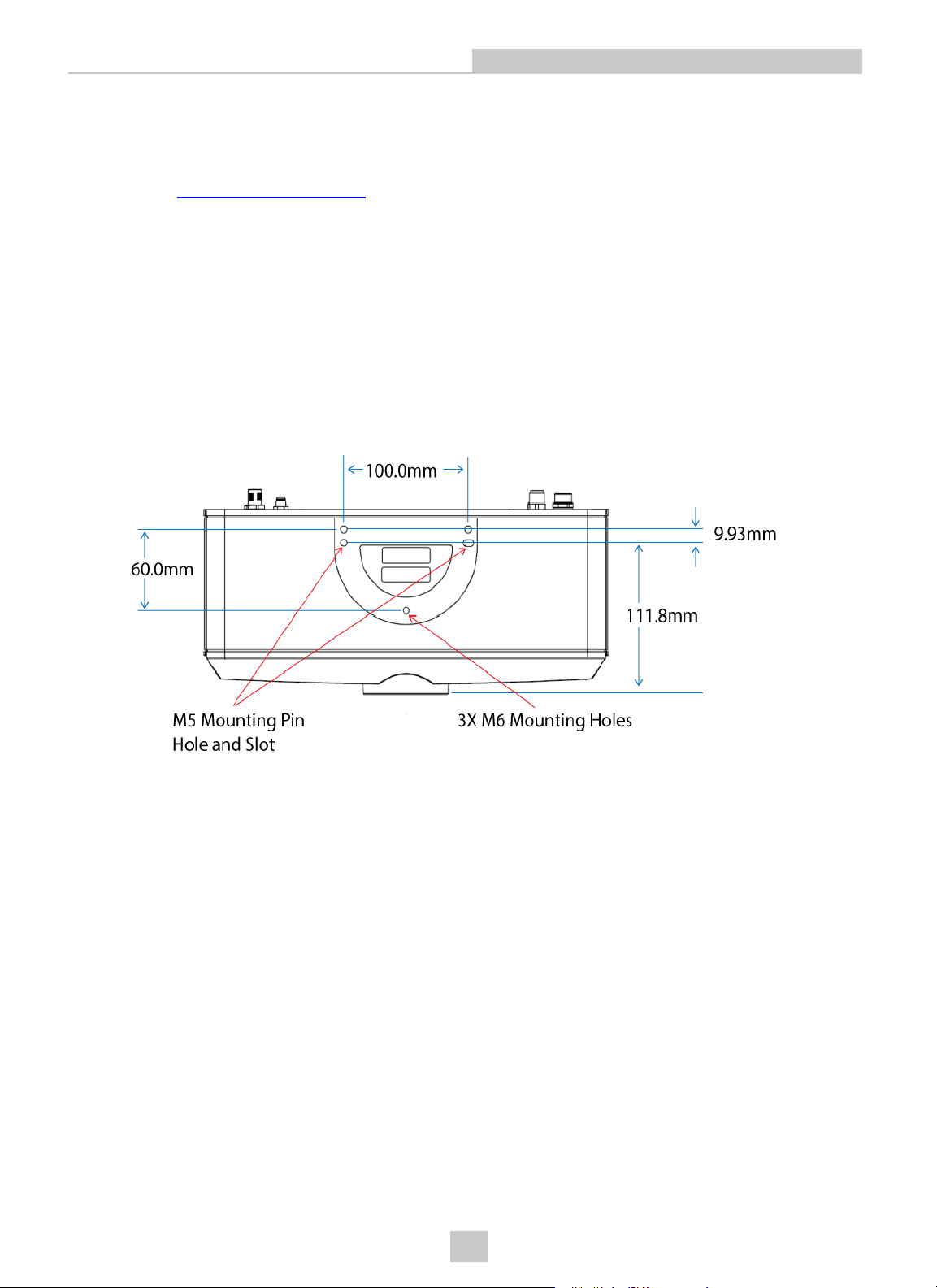
l A mounting option for your 3D-A5000 sensor.
Refer to the following diagram for physical dimensions (in mm)of the mounting options on the back of the sensor:
Precautions
To reduce the risk of injury or equipment damage, observe the following precautions when you install the Cognex
product:
l Route cables and wires away from high-current wiring or high-voltage power sources to reduce the risk of
damage or malfunction from the following causes: over-voltage, line noise, electrostatic discharge (ESD), power
surges, or other irregularities in the power supply.
l Changes or modifications not expressly approved by the party responsible for regulatory compliance could void
the user’s authority to operate the equipment.
l Ensure that the cable bend radius begins at least six inches from the connector. Cable shielding can be
degraded or cables can be damaged or wear out faster if a service loop or bend radius is tighter than 10X the
cable diameter.
l This device is certified for office use only and if used at home, there can be frequency interference problems.
l This device should be used in accordance with the instructions in this manual. Failure to do so may impair the
performance and/or protection provided by the device.
l All specifications are for reference purposes only and can change without notice.
9
Page 10
Hardware Installation
Deploy the PC and the 3D Sensor
Perform the following steps to deploy your PC and 3D-A5000 sensor:
1. Place your PC in a well-ventilated area.
2. Mount your sensor within cable-length of the PC. See Hardware Installation on page9 for measurements of the
mounting plate on the back of the sensor.
3. Connect the GigE cable of the sensor to the 10 Gigabit Ethernet adapter.
4. Connect your 3D-A5000 power cable to a 24V power supply.
Power cable pin assignments:
Pin Number Signals WireColor
1 +24VDC Red
2 Ground Black
3 Reserved
4 Reserved
5. Connect an optional hardware trigger.
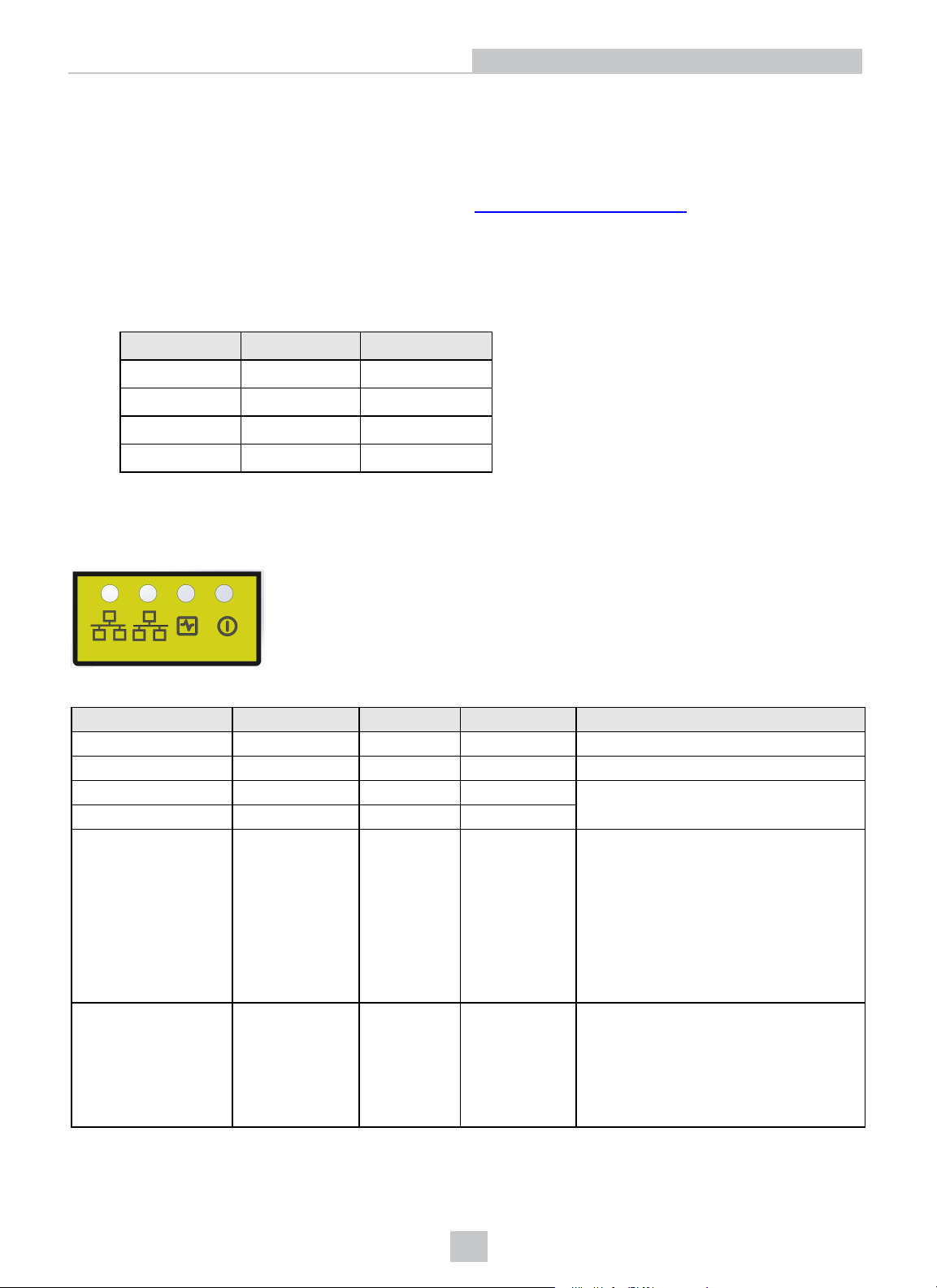
LED Indicators
Refer to the following table for a description of the status LED indicators on the front panel of the 3D sensor:
Green (Ethernet) Yellow (Ethernet) Red Green Details
OFF OFF OFF OFF Power Off
ON ON ON ON Powering Up
OFF OFF ON OFF Booting
OFF OFF ON ON
ON/OFF
N/A N/A FLASH FLASH
ON
(pulses)
OFF
ON
(pulses)
System OK
Green ON, pulses briefly every 5 seconds
Yellow ON if Ethernet link connected at
any speed, pulses with Ethernet packets
sent or received
Green (Ethernet)ON if Ethernet connected
at 10 Gbps
Firmware Update Required
10
Green and Red flash alternately indicating
an interrupted firmware update.
Sensor will not acquire images until a
successful firmware update is complete.
Page 11
Hardware Installation
Green (Ethernet) Yellow (Ethernet) Red Green Details
N/A N/A ON FLASH
In the event of a system error, the Green LED fast flashes "N" times, has a long pause, and repeats. The "N"value
indicates the error code:
1. File System Corrupt
2. No Calibration File Present
3. Cooling Fan Failure
4. Diarotator Motor Failure
5. Diarotator Controller Failure
6. Image Sensor Failure
7. Configuration EEPROM corrupt
If the 3D sensor detects multiple errors, each error is flashed with a pause between each value. For example, for errors 2,
3 and 5 the sequence would be:
l 2 fast flashes and a short pause
System Error
See the following description.
l 3 fast flashes and a short pause
l 5 fast flashes and a long pause
Then the cycle would repeat.
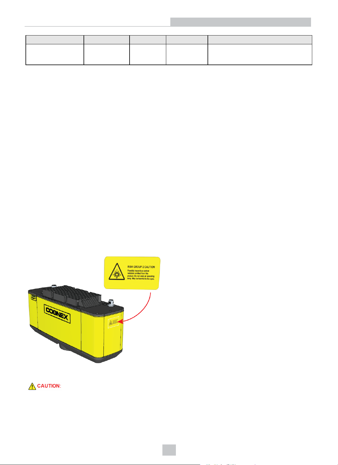
Caution Labels
Your 3D-A5000 sensor supports a caution label applied to the side of the sensor:
The label contains the following caution:
Do not stare into operating projector. The intense light may be harmful to the eyes.
Depending on how your mount the hardware in your production environment, the caution label might not be visible to
anyone operating the sensor. Find additional English and non-English labels in the packaging with your Cognex
hardware.
11
Page 12
Hardware Installation
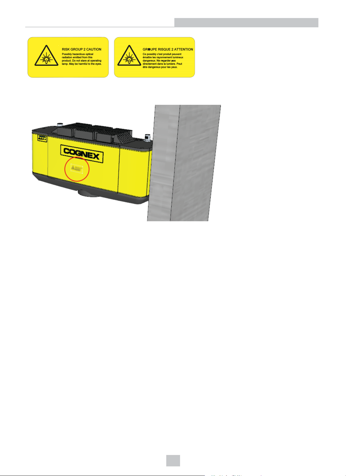
Use the non English label if the English label is not sufficient for your production environment. Place one or both labels
in a place visible to anyone operating the sensor:
12
Page 13
I/O Cable
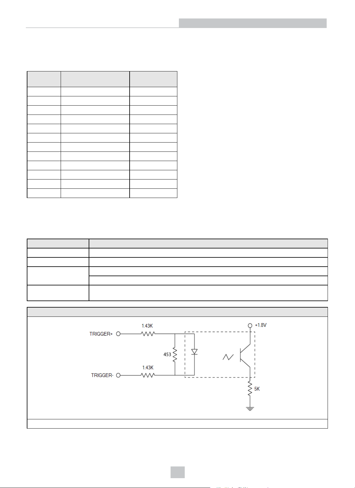
The following table describes the 3D-A5000 I/O cable:
I/O Cable
Pin
Number
1 READY+ Yellow
2 Reserved White/Yellow
3 Reserved Brown
4 READY- White/Brown
5 TRIGGER_IN+ Violet
6 TRIGGER_IN- White/Violet
7 Reserved Red
8 Reserved Black
9 TRIGGER_OUT+ Green
10 TRIGGER_OUT- Orange
11 MISSED_TRIGGER+ Blue
12 MISSED_TRIGGER- Grey
Signal WireColor
Hardware Triggers
The acquisition trigger input to the 3D sensor is opto-isolated, and the sensor will respond to a trigger event when the
voltage difference between the TRIGGER+ and TRIGGER- inputs exceeds 10V.
Specification Description
V
IH
V
IL
I
TYPE
Delay 50 µs maximum latency between leading edge of trigger and start of acquisition. Input pulse
±10 – ±28 V
0 – ±5 V
@ 12 VDC, 4 mA
@ 24 VDC, 8 mA
should be a minimum of 1ms wide.
Trigger Circuit
30V max across the input pins - transition approx. 10V (Min.)
13
Page 14
I/O Cable
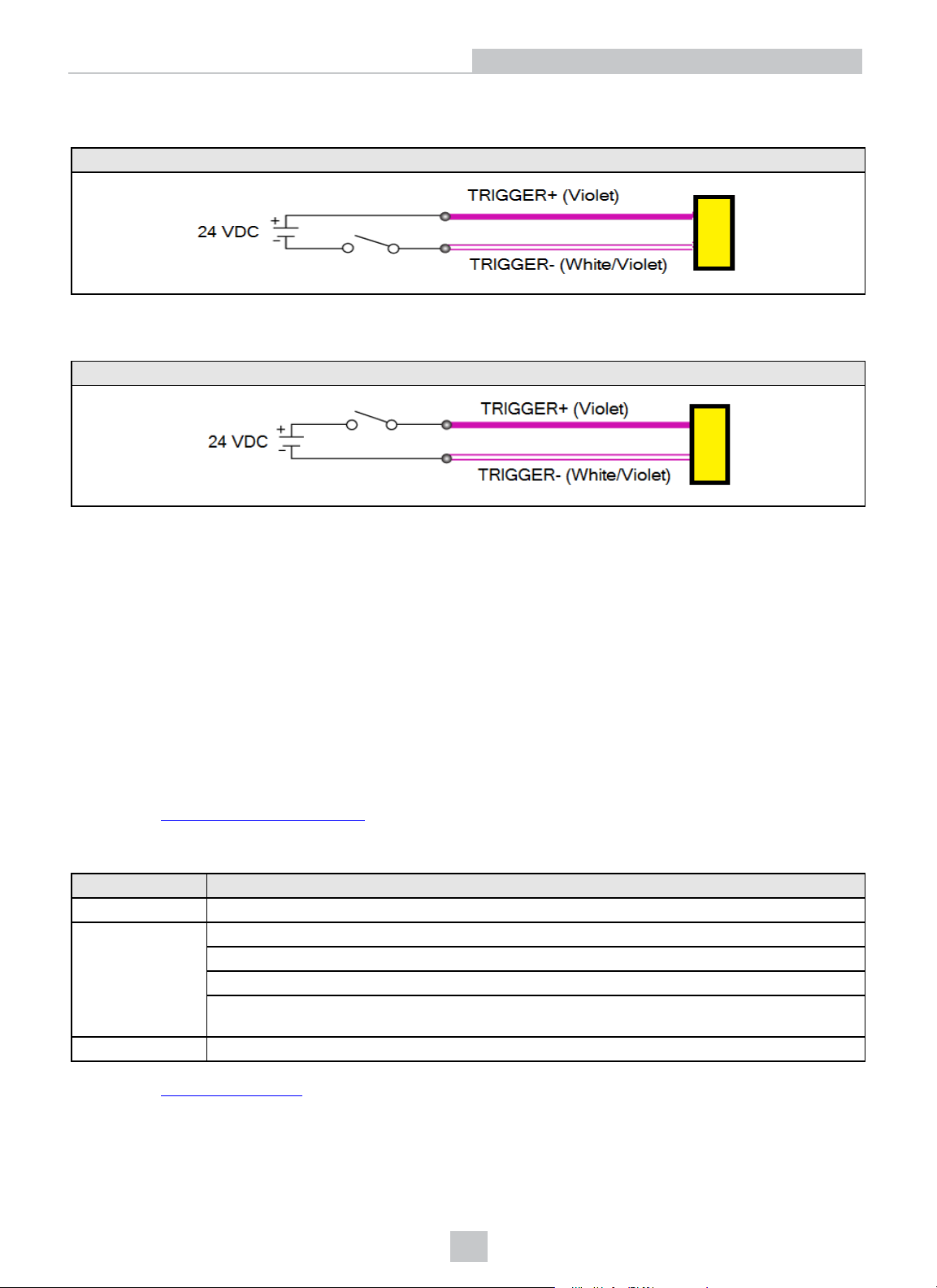
To configure the acquisition trigger as a sourcing input, connect the TRIGGER+ terminal to the high-voltage reference
(24VDC) and the TRIGGER- terminal to the output of the photo-electric sensor.
Trigger (Source)
To configure the acquisition trigger as a sinking input, connect the TRIGGER- terminal to the low voltage reference
(ground) and the TRIGGER+ terminal to the output of the photo-detector or PLC.
Trigger (Sink)
Be aware of the following I/O line behavior during acquisition:
l The sensor asserts the READY line to indicate that it will perform a hardware-triggered acquisition when it detects
a rising edge on the TRIGGER_IN line.
The sensor must be configured for hardware triggers, an acquisition start command received, and the sensor
must not be currently performing an acquisition.
l The sensor generates a 5.2 ms pulse on the TRIGGER_OUT line at the start of any acquisition sequence
(hardware trigger or software trigger)
l The sensor generates a 5.2 ms pulse on the MISSED_TRIGGER line if it detects a TRIGGER_IN signal but the
READY line is not asserted
Discrete Outputs
See the topic Hardware Triggers on page13 for details on the acquisition trigger. Your 3D-A5000 sensor supports three
other optically-isolated high-speed outputs that can be used as either NPN (current sinking) or PNP (current sourcing)
lines.
Specification Description
Voltage 26.4VDC maximum through external load
Current 50mA maximum sink current
OFF state leakage current 100µA
External load resistance 240 Ohms to 10K Ohms
Each line rated at a maximum 50mA, protected against over-current, short circuits and transients
from switching inductive loads. High current inductive loads require an external protection diode.
10µs (maximum due to opto-isolators turning on)
Delay
2
See the topic I/O Cable on page13 for the pin assignments of the 3D-A5000 sensor I/O cable.
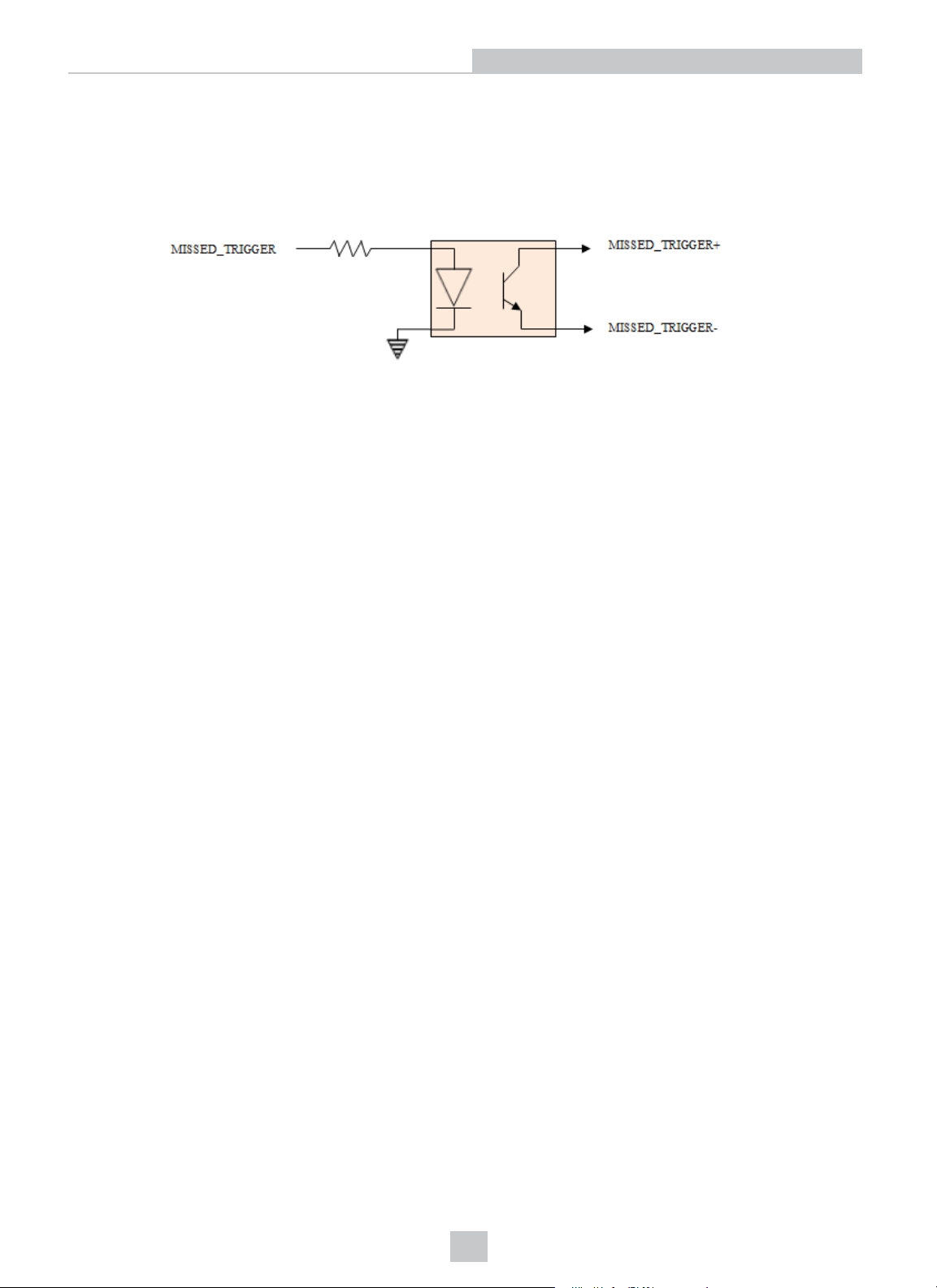
Your 3D-A5000 sensor uses an identical circuit for all the outputs the 3D sensor supports:
14
Page 15
l MISSED_TRIGGER
l READY
l TRIGGER_OUT
For example, the following figure contains a block diagram for the MISSED_TRIGGER signal:
Wiring for sourcing output:
l MISSED_TRIGGER+ to load power (e.g. PLC +24VDC)
l MISSED_TRIGGER- to load (e.g. PLC sinking input ) and return (e.g. PLC ground)
Wiring for sinking output:
I/O Cable
l MISSED_TRIGGER+ to load (e.g. PLC sourcing input ) and power (e.g. +24VDC)
l MISSED_TRIGGER- to load return power (e.g. PLC ground)
15
Page 16

Cleaning and Handling
Cleaning and Handling
Cognex makes the following recommendations for cleaning your 3D-A5000 sensor.
To clean the outside of the 3D sensor housing, use a small amount of mild detergent cleaner or isopropyl alcohol on a
cleaning cloth. Do not pour the cleaner directly onto the 3D sensor housing.
CAUTION: Do not attempt to clean any Cognex product with harsh or corrosive solvents, including lye, methyl ethyl
ketone (MEK) or gasoline.
To remove dust from the camera windows, use a pressurized air duster. The air must be free of oil, moisture or other
contaminants that could remain on the windows. To clean the window, use a small amount of isopropyl alcohol on a
cleaning cloth and gently clean the window surface. Do not scratch the windows. Do not pour the alcohol directly on the
windows.
16
Page 17
Regulations/Conformity:3D-A5000 Sensors
Regulations/Conformity:3D-A5000 Sensors
Note: For the most current CE declaration and regulatory conformity information, see the Cognex support site:
cognex.com/support.
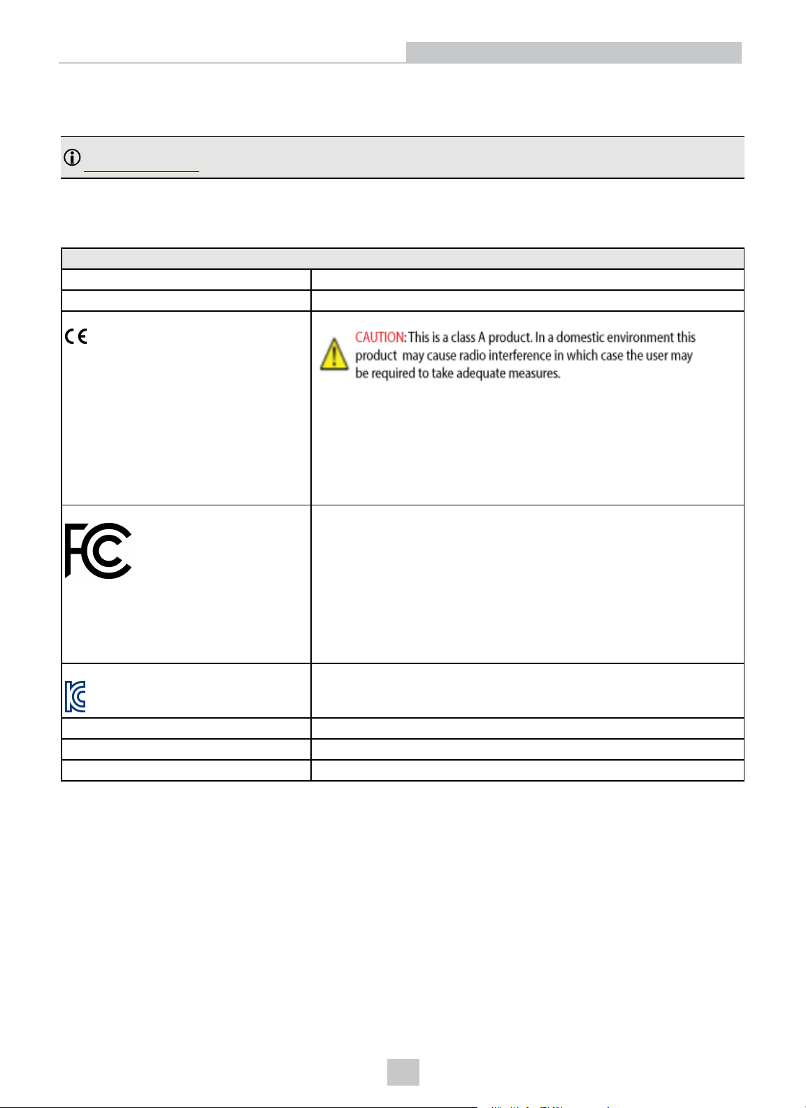
Cognex 3D-A5000 series sensors meet or exceed the requirements of all applicable standards organizations for safe
operation. As with any electrical equipment, however, the best way to ensure safe operation is to operate them according
to the agency guidelines that follow. Please read these guidelines carefully before using your device.
Safety and Regulatory
Manufacturer Cognex Corporation 1 Vision Drive Natick, MA 01760 USA
Canada ICES-003, Class A
European Community
This equipment complies with the essential requirements of the EU
Directive 2014/30/EU. Declarations are available from your local
representative.
3D-A5005; Regulatory Model R00094
3D-A5030; Regulatory Model R00095
3D-A5060; Regulatory Model R00092
FCC Class A Compliance Statement This equipment has been tested and found to comply with the limits for
KCC 3D-A5005: Regulatory Model R00094 R-R-CGX-R00094
NRTL TÜV SÜD AM SCC/NRTL OSHA Scheme for UL/CAN 61010-1
CB TÜV SÜD AM, IEC/EN 61010-1. CB report available upon request
RoHs Compliant to the most recent applicable directive.
Class A digital device, pursuant to part 15 of the FCC Rules. These limits
are designed to provide reasonable protection against harmful interference
when the equipment is operated in a commercial environment.
This equipment generates, uses, and can radiate radio frequency energy
and, if not installed and used in accordance with the instruction manual,
may cause harmful interference to radio communications. Operation of this
equipment in a residential area is likely to cause harmful interference in
which case the user will be required to correct the interference at his own
expense.
3D-A5030: Regulatory Model R00095 R-R-CGX-R00095
3D-A5060: Regulatory Model R00092 R-R-CGX-R00092
17
Page 18
For European Community Users
For European Community Users
Cognex complies with Directive 2012/19/EU OF THE EUROPEAN PARLIAMENT AND OF THE COUNCIL of 4 July 2012
on waste electrical and electronic equipment (WEEE).
This product has required the extraction and use of natural resources for its production. It may contain hazardous
substances that could impact health and the environment, if not properly disposed.
In order to avoid the dissemination of those substances in our environment and to diminish the pressure on the natural
resources, we encourage you to use the appropriate take-back systems for product disposal. Those systems will reuse or
recycle most of the materials of the product you are disposing in a sound way.
The crossed out wheeled bin symbol informs you that the product should not be disposed of along with municipal
waste and invites you to use the appropriate separate take-back systems for product disposal.
If you need more information on the collection, reuse, and recycling systems, please contact your local or regional waste
administration.
You may also contact your supplier for more information on the environmental performance of this product.
18
Page 19

 Loading...