


CODUME sa.
X
-
V
ent
II 300
Installations and Operations Guide
Version 2011-06-24

CODUME Page 2
DANGER SYMBOLS
Non-observance of instructions indicated with a danger symbol
entails a risk of injury or material damage.
Read and save these instructions
By following these instructions, we guarantee you correct
installation and safe use of this product.
Airmaster A/S disclaims any liability for damage or injury resulting
from use, non-compliant with this manual.
This guide applies to the ventilation unit X-Vent II 300.
WARNINGS
Prior to installation and commissioning, read and observe the
instructions provided in this manual.
Do not operate the unit until the service cover and grates on duct
connections have been mounted.
Do not open the service cover until the power has been cut off.

CODUME Page 3
Contents
1. GENERAL INFORMATION ....................................................................................................................................................... 4
1.1 P
REFACE
................................................................................................................................................................................... 4
1.2 Z
ONE OF USE
............................................................................................................................................................................. 4
2. DESCRIPTION ............................................................................................................................................................................. 4
2.1 M
AIN CONTROLLER FUNCTIONALITIES
....................................................................................................................................... 4
2.2 R
EGULATED EQUIPMENT
........................................................................................................................................................... 4
2.3 T
ECHNICAL SPECIFICATIONS AM II
300 .................................................................................................................................... 4
2.4 B
ASIC CIRCUIT DIAGRAM
........................................................................................................................................................... 5
2.5 C
OMPONENT NAME
................................................................................................................................................................... 5
2.6 S
TRUCTURE
.............................................................................................................................................................................. 6
3. MECHANICAL INSTALLATION ............................................................................................................................................. 7
3.2 M
OUNTING UNIT IN WALL FRAME
.............................................................................................................................................. 8
3.3 M
OUNTING PIPES AND GRATES
................................................................................................................................................ 12
3.4 C
ONNECTING THE WATER HEATING SURFACE
........................................................................................................................... 12
3.5 C
ONNECTING THE ELECTRIC HEATING SURFACE
....................................................................................................................... 15
4. ELECTRICAL INSTALLATION ............................................................................................................................................. 15
4.1 C
ONNECTING THE POWER
........................................................................................................................................................ 15
4.2 C
ONNECTING THE DISPLAY PANEL
........................................................................................................................................... 16
4.3 C
ONNECTING A
CO
2
SENSOR (OPTION
) .................................................................................................................................... 16
4.4 C
ONNECTING A
PIR
SENSOR (OPTIONAL
) ................................................................................................................................. 16
4.5 E
XTERNAL CONNECTIONS
....................................................................................................................................................... 17
4.6 S
CREEN TERMINATION
............................................................................................................................................................ 17
5. APPENDIX .................................................................................................................................................................................. 19
5.1 M
AIN DIMENSIONS
X-V
ENT II
300 WALL MODEL .............................................................................................................. 19
5.2 M
AIN DIMENSIONS
X-V
ENT II
300 WALL MODEL
PARTIALLY INTEGRATED
......................................................................... 20
5.3 M
AIN DIMENSIONS
X-V
ENT II
300 WALL MODEL
COMBI
3 .................................................................................................. 21
5.4 M
AIN DIMENSIONS
X-V
ENT II
300 ROOF MODEL
PARTIALLY INTEGRATED
......................................................................... 22
5.5 E
LECTRICAL DIAGRAM
............................................................................................................................................................ 23
5.6 C
APACITY DATA
..................................................................................................................................................................... 24
5.7 ON-
SITE TESTING OF AIR VOLUMES
.......................................................................................................................................... 26
5.9 EU
DECLARATION OF CONFORMITY
......................................................................................................................................... 27

CODUME Page 4
1. General information
1.1 Preface
This installations and operations guide contains
technical information as well as information regarding
installation and maintenance of the unit.
1.2 Zone of use
The tolerated zone of use for the air extraction
temperature is -12 ... 35 °C.
2. Description
The X-Vent II 300 is a ventilation unit with air diffusion and extraction ventilators, filters in diffusion and exhaust,
countercurrent heat exchangers and compact electronic control.
The unit is designed for installation in the room to be ventilated. Ducts for supply and exhaust air are connected either to
the back of the unit and lead out through the wall, or to the top of the unit and out through the roof.
X-Vent Controller is a compact electronic controller designed for full control of the X-Vent ventilation unit, fitted with
effective heat recovery and energy-efficient EC ventilators.
2.1 Main controller functionalities
• Unlimited control of air volume
• Control of air supply temperature
• Bypass operation (optional)
• Night cooling and background ventilation
• Manual operation or automatic operation via
weekly timer
• Operation via CTS, movement sensor or CO2
sensor
• The defrost functionalities protects the counterflow
heat exchanger from freezing over when outdoor
temperatures are low.
• Monitoring and alarm functionalities
2.2 Regulated equipment
• Inlet- and extract ventilators
• Closing damper, intake
• Bypass damper (optional)
• Electric heating surface (optional)
• Adjustment valve for water heating surface
(optional)
2.3 Technical specifications AM II 300
Power supply: 1 ~ 230 V, 50 Hz, N+PE
Duct connections: Ø200 mm.
Condensation drain: Ø16 mm
Net weight: 49.8 kg
Transportation weight (incl.
packaging):
62.9 kg
Heat exchanger: Counterflow
Filters: F5 standard
Main dimensions: 1274 x 327x 578 (WxHxD) excl. connecting pieces, incl. wall frame
Colour: Cover panels Ral 9010 (white), sub panels Ral 7024 (grey)
Specifications water heating surface
Max. operating temp.:
90 °C
Max. operating pressure: 10 bars
Capacity: * 400 W
Connection dimensions: ⅜” (DN 10)
Material pipes/fins: copper/aluminium
Open/shut time motorised
valve
< 60 s
* Capacity at:
in/out temperature 70/40 °C, water volume 15 L/h
Specifications electric heating surface
Heating stick: 1 x 230 V
Output: 1500 W
Minimum air velocity: 0.3 m/s
Thermal cutout, aut.
reset:
70 °C
Thermal cutout, man.
reset:
120 °C
CODUME Page 5
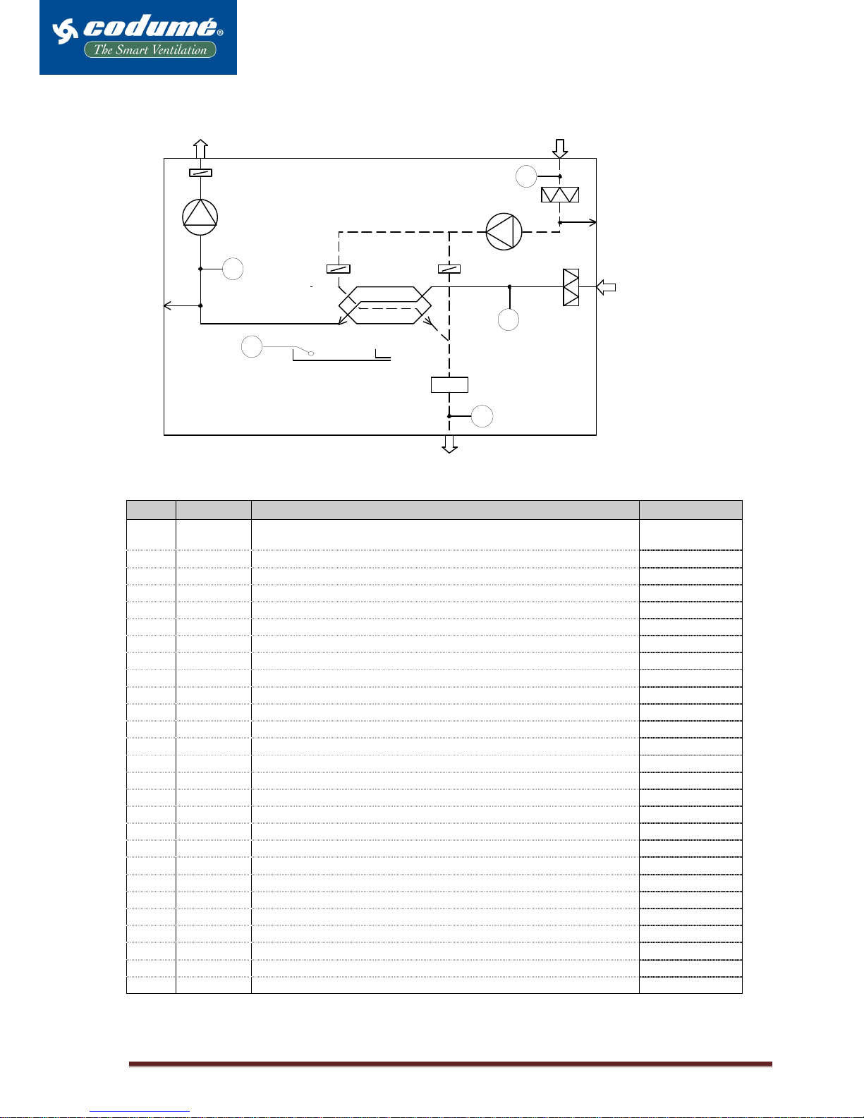
2.4 Basic circuit diagram
UDSUGNING
AFKAST
UDELUFT
F2
OT
FT CT
ET
IT
INDBLÆSNING
+
HE
CH *
BP *
MD
PU
PI
IF
EF
FI
RT
ED
FL
2.5 Component name
Pos. Description Function Spare part :
1 - Connecting spigot for exhaust air (wall model), placed at top (roof
model)
2 - Connecting spigot for intake air (wall model), placed at top (roof model)
3 F1 Inlet fan
4 F2 Exhaust fan
5 EF Exhaust filter
6 IF Intake filter (fresh air)
7 MD Motor for closing damper (motorised)
8 ED Exhaust damper (overpressure)
9 BP Bypass damper (optional)
10 HE Counter-flow heat exchanger
11 CT Condensation tray
12 FT Floater
13 - Connecting piece for condensation drainage
13 a - Lead-in for condensation drainage
14 RT/ FL Room temperature sensor / flow sensor
15 OT Outdoor temperature sensor
16 ET Exhaust temperature sensor
17 PI Pressure tap for air volume measurement, supply
18 PU Pressure tap for air volume measurement, exhaust
19 - Extract opening right side
20 - Inlet opening in front
21 - Power hook-up on right side
22 - Power hook-up on mounting plate for main box
23 - Main box
24 CH Post-heating surface (optional)
25 IT Inlet temperature sensor
26 Condensate Pump (optional)
INTAKE EXHAUST
EXTRACT
INLET
CODUME Page 6
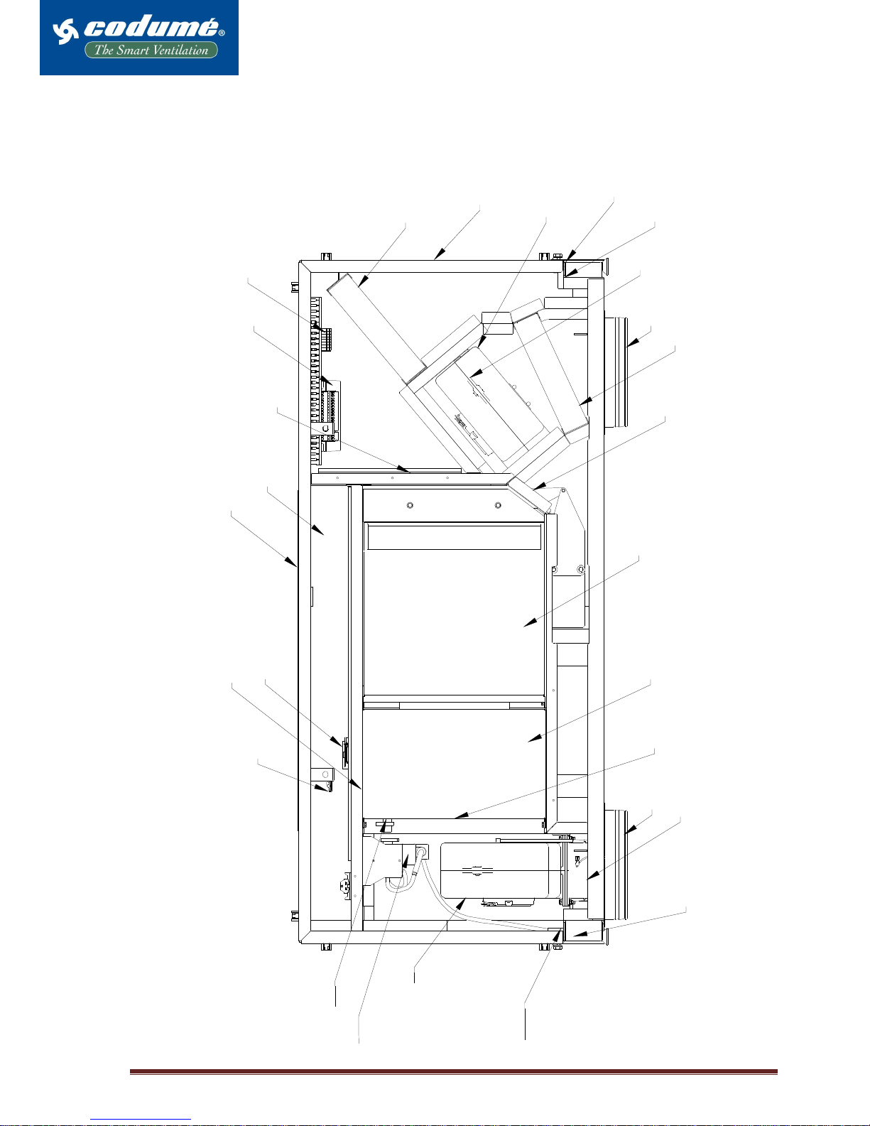
2.6 Structure
The unit seen from below, without service cover.
1
2
3
4
6
5
7
8
9
10
13
11
20
23
22
14
19
15
17
21
12
24
25
13a
18
16
2
6
CODUME Page 7
3. Mechanical installation
The installer is responsible for safely and securely fastening the unit to the wall.
Note: When lifting the unit, it is important to place a protective underlay, to avoid scratching the base plate. The underlay
can consist of, e.g. thick cardboard or a similar material.
The mechanical installation involves
• Marking, drilling of holes for connecting ducts and mounting of wall frame
• Mounting of unit in wall frame
• Installation of pipes and grates through walls or over roof, depending on model
• Mounting of panels
Important: Before drilling holes in wall or roof, check that there is at least 0.5 m between the wall and the unit’s exhaust
end. If the exhaust end is facing out towards glass panes, that distance must be greater. If these minimum distances are
not observed, there is a risk of increased noise from the unit.
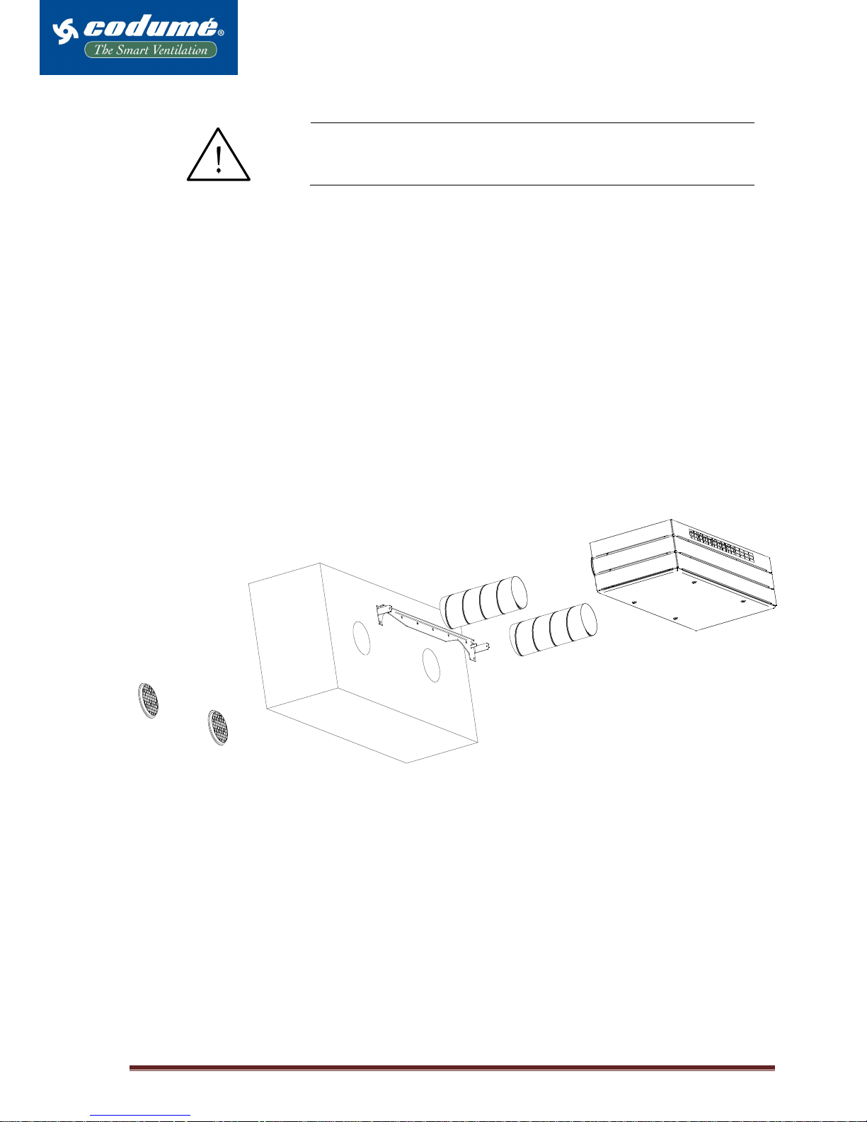
Simplified picture illustrating mounting of unit on wall frame.
CODUME Page 8
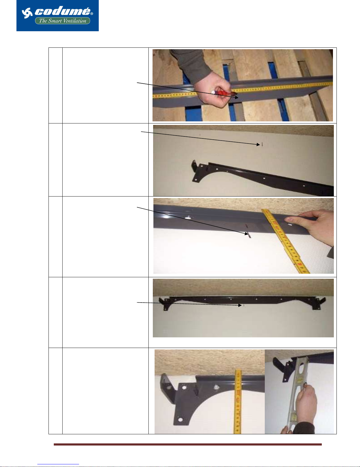
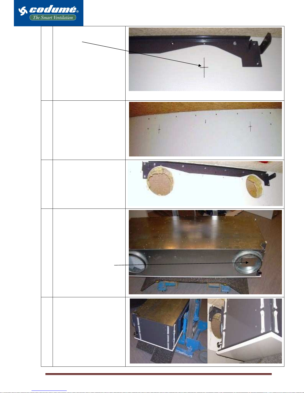
3.2 Mounting unit in wall frame
1
Start by finding the centre of
the wall frame using a ruler.
The centre measurement for
the wall frame is 62 cm. Mark
the measurement.
2
Next mark the middle of the
wall or the location you wish
to place the centre of the unit.
3
Now line up the two marks.
If you like, you can place the
wall frame all the way up to
the ceiling. If you do this,
there will be a 6 mm gap
between the top of the unit
and the wall.
4
Now that the wall frame is
provisionally hung, you can
mark holes for screws and the
centre of supply and exhaust.
The duct size is Ø200mm.
The recommended hole
diameter is Ø210-215 mm, so
the pipes can be insulated
subsequently.
5
Horizontally measure and
mark distance down to centre
of supply/exhaust, and mark
centre in vertical direction.
CODUME Page 9
6
This clearly indicates the
marking of the centre of the
intake hole.
Note: The length of the two
pipes depend of the wallthickness.
7
All necessary markings show.
Note: The holes for the pipes
should have a downward start
of 1-2%, to prevent hard rain
from penetrating the unit.
8
Here, both holes have been
drilled, and the wall frame is
now securely fastened to the
wall.
Note: The screw type used
depends on the wall material.
9
Place the unit on a thick
underlay, such as cardboard
or the like, to prevent
scratches in the base plate. It
is important that the unit is
stable on the lift.
Note: Remember to remove
tape holding the discharge
damper in the transport
position.
10
The unit is on the underlay
and is safely and securely
placed on the lift.
In the picture on the right, the
unit is raised and can now be
adjusted to the two guide
hooks placed on the wall
frame.

CODUME Page 10
11
Make final adjustments to the
unit to unable it to be pushed
far enough over the hooks
that it cannot fall back out
again.
In the picture on the right, the
unit is hanging from the two
guide hooks.
At the bottom of the picture
one of the adjustment screws
shows.
12
Now, fasten the unit to the
wall frame, using the two
factory-supplied M8 bolts,
one on each side.
To get the unit to hang
properly relative to the wall,
adjust it by screwing the two
adjustment screws situated
just over the base plate.
Use a no. 13 screw wrench.
13
The unit must hang
horizontally; therefore, it is
important to check and
readjust.

CODUME Page 11
14
Attach the display panel.
The photo shows the
protected earth terminal.
L = Phase brown
0 = Blue
AC = Connection of cooling
module (optional)
Terminal block X3
Display panel attached.
15
The unit is now hung, and the
factory-supplied panels can
be clicked onto the mounted
clips.

CODUME Page 12
3.3 Mounting pipes and grates
Mount two Ø200 mm pipes through the wall with a 1-2% outward slant. The length of the pipes is calculated based on
the thickness of the wall.
Remember to remove tape holding the damper in the exhaust in transport position.
Finally, mount Ø200 mm grates with slats pointing down. Remember to joint between grate and outer wall. It is important
that the penetrations not are twisted or forced onto the unit’s connecting pieces, to avoid an elevated noise level.
3.4 Connecting the water heating surface
The unit can be purchased complete with water heating
surface (optional), motorised valve, automatic heatretaining thermostat and air escape valve internally
mounted and threaded. The heating unit has been
tested for leaks and undergone final inspection in
accordance with DS 469.
Dimensioning of pipes, valves and connections
to the unit must always be carried out by authorised
personnel.
36.0
102.0
40.0
Connection
Lead the hot water connection through the cabinet on the right side or at the top to the connecting pieces placed inside
the unit, behind the service cover. Connect the forward hot water connection to the connecting piece market FORWARD
and the return to the connecting piece marked RETURN. See the below dimensioned sketch for further instructions
regarding lead-through of the water connection.
Note: The regulating valve (3) requires clean unit water in order to function optimally, without disruptions from blockage
in the valve. Airmaster A/S recommends that a dirt trap and continuous regulating valve be fitted in the hot water
connection according to the below-mentioned simplified diagram.
Simplified diagram for external connection
Simplified diagram for internal structure
1: Water heating surface
2: Valve housing with presetting N
3: Valve housing with presetting 6
4: Air escape valve
IT/FS: Temperature and flow sensor
TM: Thermo motor
TV: Thermostatic heat-retaining valve
Shutoff valve (not Airmaster delivery)
X-Vent II unit
RETURN
FORWARD
RETURN 3/6” (DN 10)
FORWARD 3/6” (DN 10)
AIRFLOW
CODUME Page 13
5: Union connections (if mounted)
6: Remote sensor
Continuous regulating valve (not Airmaster
delivery)
Dirt trap (not Airmaster delivery)
Ventilation
Open water flow and aerate the system using the air release valve (4). After a short while the water flow should be silent,
with no noise from air.
The aeration is carried out with fully open valves, dismounted heat-retaining thermostat (TV) and thermal motor
(TM).
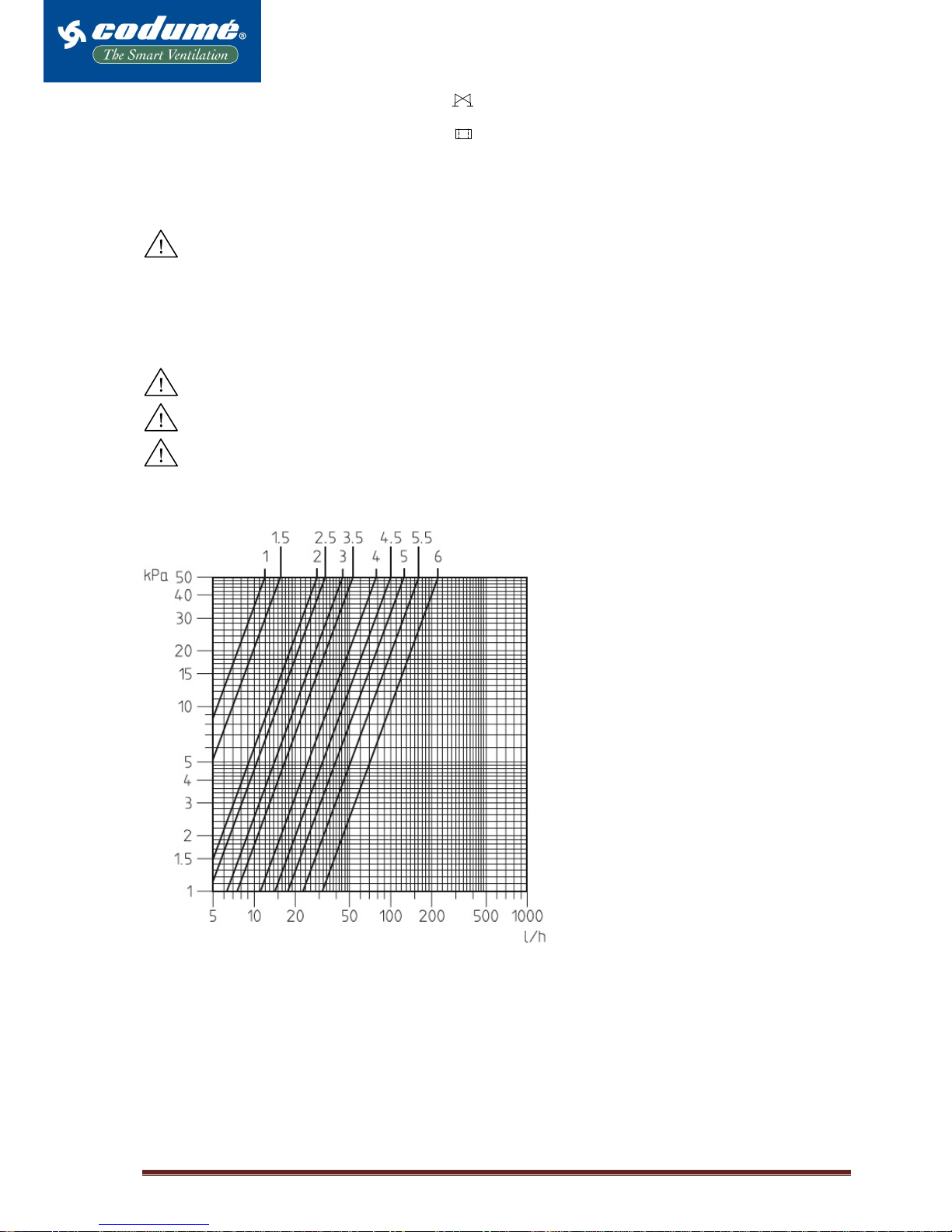
Adjustment of motorised valve
The unit comes with regulating valve (3) type TRV-2S preset to 6 – fully open valve. The regulating valve is preset
according to the diagram below, such that the prescribed flow is achieved with differential pressure of ∆H, which is
available to the unit in nominal operating conditions.
Remember that the unit must be aerated and rinsed prior to adjustment.
It is important to preset the valve so the maximum water flow is not exceeded.
If the differential pressure over the regulating valve is greater than 30 kPa, you risk a flow noise from the valve.
Diagram for determination of pressure loss in the water circuit and for presetting the regulating valve (3) TRV-2S.
Setting example:
Water flow: 15 l/h
Desired drop in pressure: 10 kPa
Setting value: 2,5
Presetting key for TRV-2S:
Plumbing no. 403399-411
Calculation of heating needs
The heat requirement for heating air from temperature
after heat recovery to the desired supply temperature is
calculated at 20 °C and 101.3 kPa:
Q = 0.34 ⋅⋅⋅⋅ qv ⋅⋅⋅⋅ (IT – t) [ W ]
where
q
v
air volume in m3/h
IT desired supply temperature
t = 15.9 °C temperature prior to post-heating
surface
Conditions: - outdoor temperature –12 °C
- room temperature 22 °C
- temperature rate of efficiency 82%

CODUME Page 14
Calculation of water volume
The flow-through volume of water is calculated at 20 °C
and 1 bar:
qw =
( )
RF
tt16,1
Q
−⋅
[ L / h ]
where
Q heating needs
tF water temperature forward
tR water temperature return

CODUME Page 15
Setting the heat-retaining valve
The heat-retaining valve (2) type RA-N 10 is factory-set to N, fully open valve. The valve is preset to 3.5.
The setting zone of the sensor element (TV) type RA is factory-set to a min. of 1.5 to ensure a minimum heating surface
temperature of approx. 14°C, provided that hot water is available.
Frost-resistance
• The heat supply or water flow must never be interrupted/shut off in frosty weather
conditions, e.g. on weekends and during holiday periods.
• The flow temperature must never drop below 40 °°°°C in frosty weather conditions.
3.5 Connecting the electric heating surface
The unit comes complete with electric heating surface and safety thermostats internally installed and wired.
Note the greater current collection with electric heating surfaces (see the electrical installation section).
Safety functionalities of electric heating surface
The electric heating surface is protected against overheating in accordance with DS 447 thanks to two safety thermostats
that disconnect the heating surface in case of overheating.
• One thermostat cuts out the heating surface at 70 °C and has an automatic reset
• The other thermostat cuts out the heating surface at 120 °C and has a manual reset
Furthermore, the unit is fitted with air volume monitoring
• which at air speeds of less than 0.3 m/s cuts out the heating surface and automatically re-connects it again when the air
speed is greater than 0.3 m/s.
4. Electrical installation
The electrical installation must be performed by an authorised electrician.
Fuse and supply separators must be mounted as regulated in the
permanent installation for the unit.
Fuse and supply separator are not delivered by Airmaster.
Electrical installation includes:
• Connection of conventional power
• Connection of display panel
• Connection of any other accessories, such as CO2 sensor, PIR sensor or CTS connection
4.1 Connecting the power
Connect the power according to the electrical diagram 23. Size the power cable according to applicable rules and
regulations, taking into account existing conditions at the installation site.
Mount the power cable in the terminal block on the right side of the unit (pos. 21) and connect terminals L, N and rack (see
item 14 in mounting unit on wall frame).
Note that the control panel and any other signalling devices must be installed before the power is switched on.
AM II 300
Without heating surface /
with heating surface
Electric heating surface
Elec. power supply: 1 ~ 230 V + N + PE / 50 Hz 1 ~ 230 V + N + PE / 50 Hz
Output: 78 W 1500 W
Full-load power: 0.6 A 6.5 A
* Connecting terminals: 0.75 mm2 0.75 mm2
Max. fuse: 20 A 20 A
CODUME Page 16
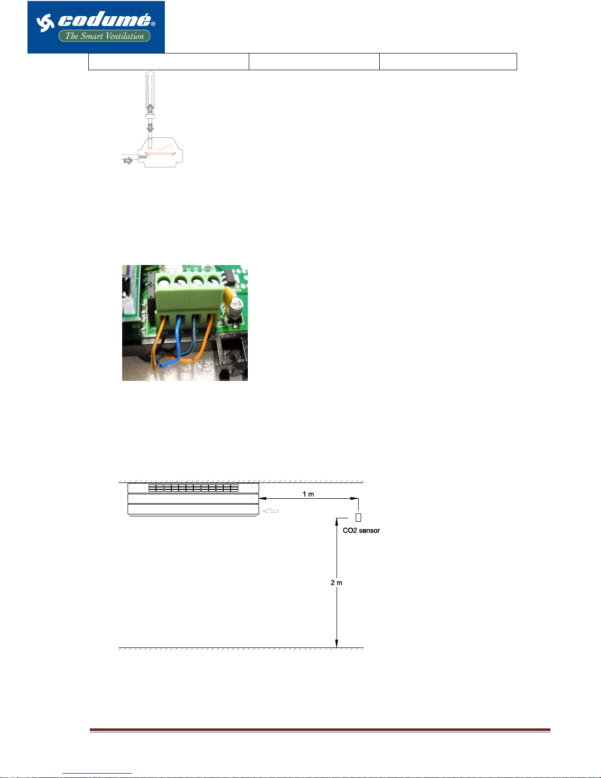
Leakage power: <= 3.O mA
Operation of spring terminal with screwdriver:
1. Open terminal by pressing on the spring.
2. Insert conductor
3. Remove the pressure on the spring.
4.2 Connecting the display panel
The delivery includes a separate display panel, with 3 m cable internally wired to the control box (pos. 23, see page 5
and 6). Connect the display panel according to the electrical diagram, page 23. Mount the connecting cable via the
cable lead-through on the right side of the unit (pos. 21, see page 5 and 6).
Mount the display panel at a suitable height on the wall in the same room as the ventilation unit, and so that it can also
be pulled out to adjoining rooms. The maximum cable length is 30 m.
The connecting cable for the display panel is a 2x2 conductor, twisted-pair
screened cable which must be connected properly according to the following
instructions:
1. Sheath and screen foil are stripped as close to the connecting terminals
as possible for the sake of EMC noise (see photo on left).
2. Be careful removing the conductors’ insulation, so as not to damage or
break them.
3. Maintain the paired twisting of the conductors to the terminals.
4. Terminate the screen at the main box, as shown in section 4.6
4.3 Connecting a CO2 sensor (optional)
Connection of CO2 sensor and transformer is done in accordance with the electrical diagram section, 5.5.
The CO2 sensor comes pre-programmed for use with the X-Vent II series. If you prefer a different configuration, please
contact Airmaster A/S. For configuration of the control, see the manual X-Vent Controller – function and menu
overview.
Terminate the screen at the main box, as shown in section 4.6
Recommended location of the X-Vent
CO2 sensor:
• Approx. 1 m from the unit’s
exhaust opening
• Approx. 2 m above floor level
• REMEMBER to keep a distance to
open windows and doors.
4.4 Connecting a PIR sensor (optional)
Connect (PIR) type ”Scantronic 420” movement sensors to the control box as instructed in the electrical diagram, page
23. On installation, refer to the instructions accompanying the PIR sensor (Sensor of movement). For configuration of
the control, see the guide X-Vent Controller – functionalities and menu overview.
Extract
CODUME Page 17
Terminate the screen at the main box, as shown in section 4.6
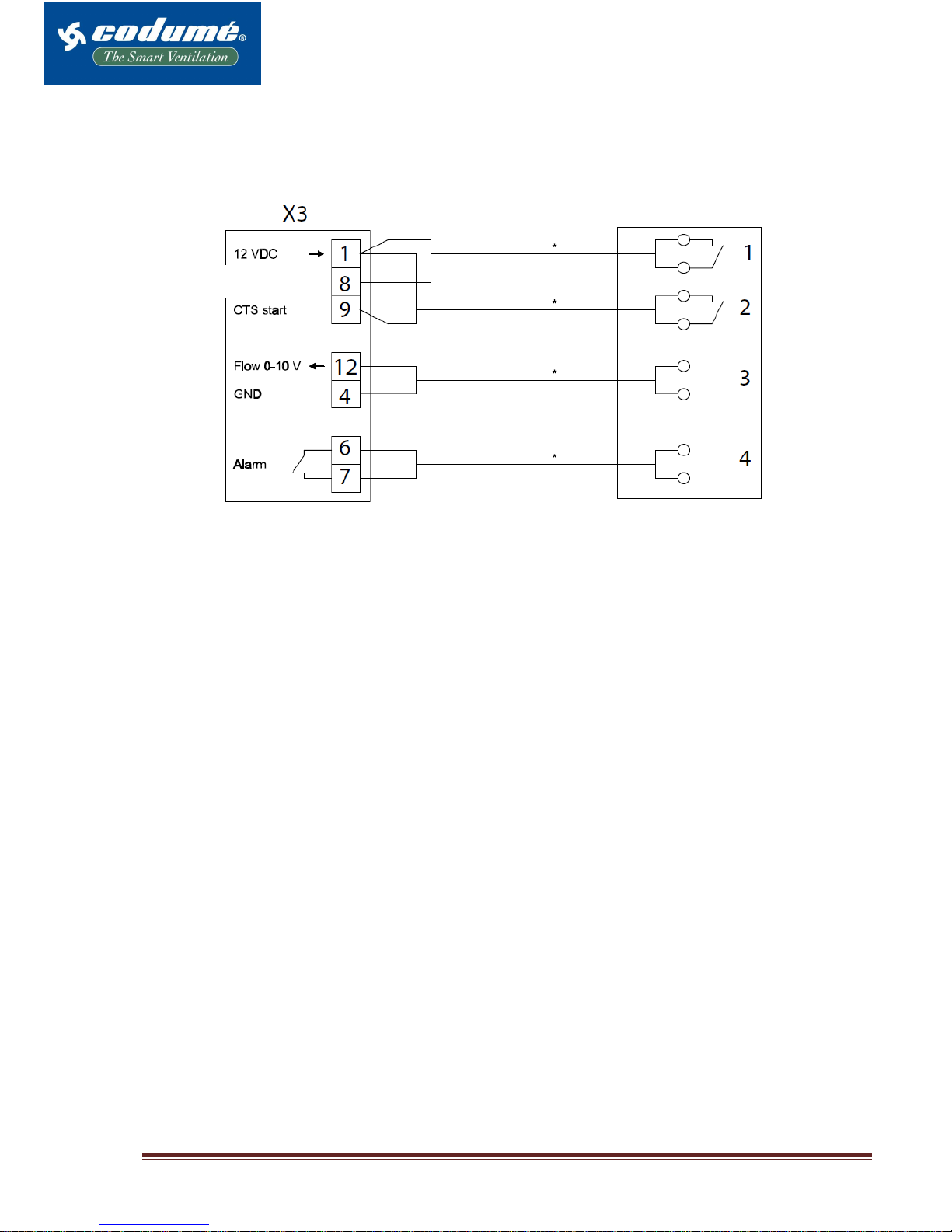
4.5 External connections
Make external connections as shown in the following diagram.
Terminate the screen as shown in section 4.6
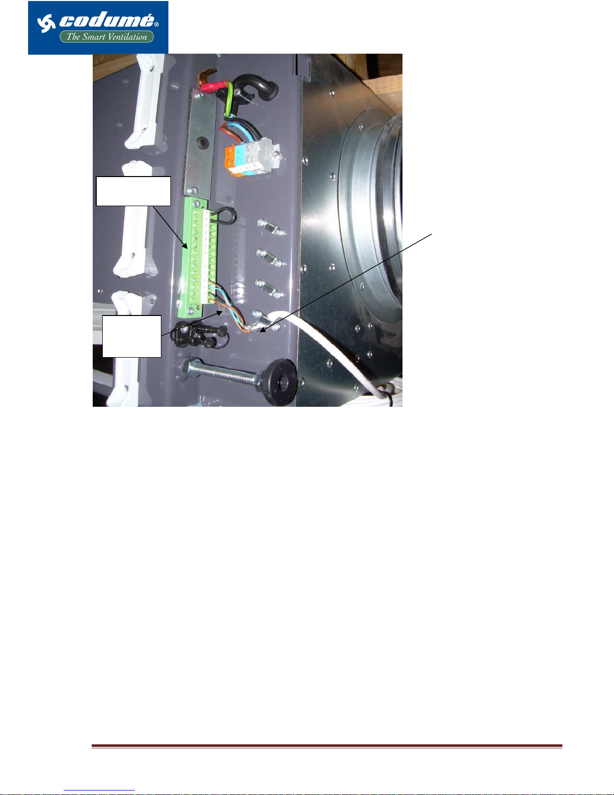
4.6 Screen termination
Manual start
CODUME Page 18
Terminal block
X3
Display
connection
Bend screen and place under
clamps, then tighten screws.
Note: The screen is not
terminated at the display and
external sensors.

CODUME Page 19
5. Appendix
5.1 Main dimensions X-Vent II 300 WALL MODEL
a
g g
b
e
i
k
n
h
p
q
m
l
o
A
B
C
E
D
1
2
3
4
B
E
C
D
5
6
r
A
a b c d e f g h i k l m n o p q r s t u
AM II 300 1274 578 - - 327 - 200 130 157,5 897 324 152 6 20 36 35 45 - - -
A = Bottom
B = Inlet side
C = Left side
D = Right side
E = Back side
1 = Exhaust
2 = Intake
3 = Inlet
4 = Extract
5 = Wall frame
6 = Center holes

CODUME Page 20
5.2 Main dimensions X-Vent II 300 WALL MODEL partially integrated
b
A
B
E
d
B
3
C
D
e
C
D
o
i
k
p
q
E
4
5
6
g g
a
c
f
m
l
h
n
r
A
a b c d e f g h i k l m n o p q r s t u
AM II 300 1274 578 1244 214 327 564 200 130 157,5 897 324 152 6 20 36 35 45 - - -
1 = Exhaust
2 = Intake
3 = Inlet
4 = Extract
5 = Wall frame
6 = Centre holes
A = Bottom
B = Inlet side
C = Left side
D = Right side
E = Back side

CODUME Page 21
5.3 Main dimensions X-Vent II 300 WALL MODEL combi 3
A
B
C
E
D
1
2
3
4
B
E
C
D
5
6
a
g g
b
A
e
h
s
n
m
l
o
r
i
k
p
q
u
t
s
a b c d e f g h i k l m n o p q r s t u
AM II 300 1274 578 - - 327 - 200 130 157,5 897 324 152 6 20 36 35 45 125 210 547
1 = Exhaust
2 = Intake
3 = Inlet
4 = Extract
5 = Wall frame
6 = Centre holes
A = Bottom
B = Inlet side
C = Left side
D = Right side
E = Back side

CODUME Page 22
5.4 Main dimensions X-Vent II 300 ROOF MODEL partially integrated
a
b
k
h
d
f
i
n
m
l
g g
c
A
B
C
E
D
1
2
3
4
B
E
C
D
e
5
6
p
q
o
r
A
a b c d e f g h i k l m n o p q r s t u
AM II 300 1274 578 1244 214 327 564 200 217 157,5 897 324 152 6 20 36 35 45 - - -
1 = Exhaust
2 = Intake
3 = Inlet
4 = Extract
5 = Wall frame
6 = Center holes
A = Bottom
B = Inlet side
C = Left side
D = Right side
E = Back side

CODUME Page 23
5.5 Electrical diagram
PE
L
N
PE
P1
L
N
AC
A2
(*1)
X3-14
(*2)
S2
X3-1
X3-4
X3-2
X3-3
GND
12V
0V
B
A
X3-13
A1
B1
(*1)
1
2
7
8
X3-5
X3-11
X3-4
X3-12
GND
B2
(*1)
12V+
12V-
NC
NC
X3-1
X3-4
X3-10
GND
Manuel start
(*1)
1
2
X3-1
X3-8
CTS start
(*1)
X3-1
X3-9
X3-12
X3-4
CTS flow
(*1)
Alarm
(*1)
0-10V
GND
X3-6
X3-7
< 24V/100mA/2VA
S1
X3-1
12V (DC)
X3-2 -RS485(B)
X3-3 +RS485(A)
X3-4 GND (DC)
X3-5 24 VAC+ (*1)
X3-6 Alarm output terminal 1
X3-7 Alarm output terminal 2
X3-8 Manuel start input
X3-9 CTS start input
X3-10 PIR signal input
X3-11 24 VAC- (*1)
X3-12 0-10V signal input
X3-13 Condensed terminal 1
X3-14 Condensed terminal 2
(*1)
Option
(*2) Jumper has to be removed if A2 is mounted
A1 Ventilation unit
A2 Cooling unit
B1 CO2 sensor (*1)
B2 PIR sensor (*1)
P1 Display panel or LON module
S1 Alarm switch
S2 Condensed float switch
Manuel start (*1) See section ”4.3.5 External connections”
CTS start (*1) See section “4.3.5 External connections”
CTS flow (*1) See section ”4.3.5 External connections”
Alarm (*1) See section ”4.3.5 External connections”

CODUME Page 24
5.6 Capacity data
Operation/Capacity at 35 dbA
Operation/Capacity at 30 dbA

CODUME Page 25

CODUME Page 26
5.7 On-site testing of air volumes

CODUME Page 27
Test of air volumes are made with help from a differential pressure – manometer and can be read in the following
diagrams.
Placement of the pressure connecting piece:
Inlet air: Right side at the back.
Exhaust air: Left side at the back.
Air volume measured on pressure taps.
WALL MODEL
ROOF MODEL
5.9 EU declaration of conformity
Inlet air
Exhaust air
Inlet air
Exhaust air

CODUME Page 28
Product X-Vent II 300
Is compliant with the following directives:
Directives The Machinery Directive 2006/42/EC
The Low Voltage Directive (2006/95/EC)
The EMC Directive (2004/108/EU)
CODUME sa.
www.codume.eu
info@codume.eu
Tel : +32 2 511 20 10
Fax : +32 2 511 23 59
 Loading...