

Page 1
INSTALLATION MANUAL
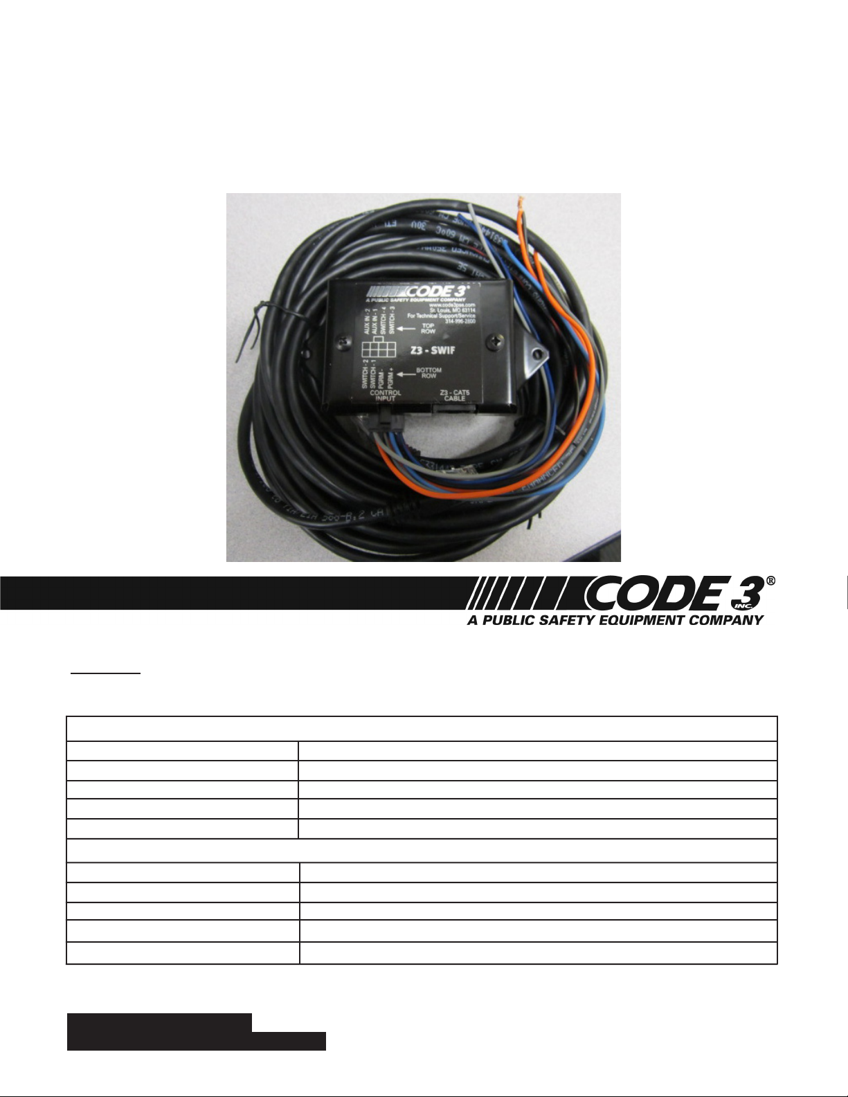
Z3-SWIF
STEERING WHEEL INTERFACE - FORD PI UTILITY & SEDAN
Mount the Z3 Steering Wheel Interface Box in the desired location using (2) user supplied screws. Note: This box
should not be mounted on the exterior of the vehicle!
Connect the Z3-SWIF Input Control wires according to the chart below.
Z3-SWIF INPUT CONTROL WIRING CHART
Z3-SWIF INPUT WIRE 14 WAY POLICE BASE SIGNAL POWER CONNECTOR
ORANGE/BLACK STRIPE POLICE 4 BUTTON CONTROLLER---BUTTON 1 OUTPUT
ORANGE POLICE 4 BUTTON CONTROLLER---BUTTON 2 OUTPUT
BLUE/BLACK STRIPE POLICE 4 BUTTON CONTROLLER---BUTTON 3 OUTPUT
BLUE POLICE 4 BUTTON CONTROLLER---BUTTON 4 OUTPUT
ADDITIONAL Z3-SWIF CONTROL INPUT WIRING
Z3-SWIF INPUT WIRE OPTIONAL CONNECTIONS
GRAY/BLACK STRIPE OPTIONAL GROUNDED SWITCH (E.G. HIDDEN GUN LOCK)
GRAY OPTIONAL GROUNDED SWITCH (E.G. REMOTE ACTIVATION SWITCH)
BLACK/RED STRIPE NOT USED (NO CONNECTION)
BLACK NOT USED (NO CONNECTION)
For future reference record your product's serial no. here __________________________________________
IMPORTANT:
Read all instructions and warnings before installing and using.
This manual must be delivered to the end user of this equipment.
INSTALLER:
Page 2

CONFIGURING Z3-SWIF - ON BENCH:
NOTE: A Z3 Amplier with the Z3 Control Head is required in order to congure the Z3-SWIF. The Z3 Amplier will not activate
any outputs or siren tones during conguration. Only the Z3 Control Head indicators will be lit to indicate which function is
congured.
1) Connect the Z3 Control Head to the CONT HEAD port of the Z3 Amplier using a CAT-5 cable.
2) Connect the Z3-SWIF to the AMP-2 port of the Z3 Amplier using a CAT-5 cable.
3) Connect the Z3-SWIF INPUT HARNESS to the CONTROL INPUT port of the Z3-SWIF.
4) Connect the Z3 INPUT/OUTPUT HARNESS to the CONTROL INPUT/OUTPUT port of the Z3 Amplier.
5) Connect the Z3 AMPLIFIER POWER HARNESS to the Z3 Amplier (lower right power port).
6) Ground the BLACK wire of the Z3 AMPLIFIER POWER HARNESS.
7) Connect the RED wire of the Z3 AMPLIFIER POWER HARNESS to +12VDC.
8) Connect the IGN wire of the Z3 INPUT/OUTPUT HARNESS to +12VDC.
a. NOTE: The Z3 Control Head will power up and beep to indicate that the system is operating.
9) Verify that all functions on the Z3 Control Head are off.
10) Connect the PGRM+ wire to the PGRM- wire on the Z3-SWIF INPUT HARNESS.
a. NOTE: The Z3 Control Head will ash all 8 ArrowStik indicators and beep three (3) times to indicate that conguration mode
has been started.
11) Activate the input to be congured by connecting it to the PGRM- wire (see Table 1).
a. NOTE: The existing congured functions will be displayed on the Z3 Control Head.
12) Activate any functions on the Z3 Control Head that are to be congured to the selected input.
a. NOTE: DIM cannot be activated at the same time as any 3-Level switch. Only one ArrowStik mode can be activated at a
time. Only one Tone can be activated at a time (see Table 2).
13) Disconnect the input being congured from PGRM- wire.
14) Verify that all functions on the Z3 Control Head are off.
15) Repeat steps 11 through 14 for each Z3-SWIF input as desired.
16) To end conguration disconnect the PGRM+ wire from the PGRM- wire.
a. NOTE: The Z3 Control Head will ash all 8 ArrowStik indicators and beep three (3) times to indicate that conguration
mode has been ended and the conguration has been saved.
b. If additional Z3-SWIF units require conguring, go to step 6 of ‘CLONING Z3-SWIF’ to download this conguration.
17) The system is now in normal mode of operation.
Table 1: Z3-SWIF Factory Settings
INPUT FUNCTION ACTIVATED
SWITCH - 1 (ORANGE/BLACK) Level 1
SWITCH - 2 (ORANGE) Level 2
SWITCH - 3 (BLUE/BLACK) Level 3
SWITCH - 4 (BLUE) Auxiliary Button ‘A’
AUX IN – 1 (GRAY/BLACK) Auxiliary Button ‘B’
AUX IN – 2 (GRAY) Auxiliary Button ‘C’
PGRM + Conguration Wire 1
PGRM - Conguration Wire 2
NOTE: Do not connect PGRM + and PGRM – to anything when Z3-SWIF is in normal operating mode.
Table 2: Z3-SWIF Tone Indicators
TONE BUTTONS LIT TONE FUNCTION ACTIVATED
WAIL WAIL
YELP YELP
ALT TONE ALT TONE
WAIL and ALT TONE MANUAL
YELP and ALT TONE AIR HORN
2
Page 3

CLONING Z3-SWIF:
NOTE: A Z3 Amplier with the Z3 Control Head is required in order to clone the Z3-SWIF. The Z3 Amplier will not activate any
outputs or siren tones during conguration. Only the Z3 Control Head indicators will be lit to indicate which function is cong-
ured.
1) Set up the Z3 system as detailed in ‘CONFIGURING Z3-SWIF - ON BENCH’ steps 1 through 9.
a. NOTE: Make sure to start with a precongured Z3-SWIF in step 2.
2) Connect the PGRM+ wire to the PGRM- wire on the Z3-SWIF INPUT HARNESS.
a. NOTE: The Z3 Control Head will ash all 8 ArrowStik indicators and beep three (3) times to indicate that conguration mode
has been started.
3) Verify that no Z3-SWIF switch inputs are activated.
4) Press and hold (approximately 1 second) the DIM button on the Z3 Control Head to upload (extract) the conguration from the precongured Z3-SWIF.
a. NOTE: The ArrowStik indicators work as a progress bar to indicate that the conguration is being uploaded. The upload is
complete when all ArrowStik indicators turn off.
5) On the Z3-SWIF INPUT HARNESS, disconnect the PGRM+ wire from the PGRM- wire.
a. NOTE: The Z3 Control Head will ash all 8 ArrowStik indicators and beep three (3) times to indicate that conguration mode
has been ended and the conguration has been saved.
6) Disconnect the precongured Z3-SWIF from the Z3 system.
7) Connect a non-congured Z3-SWIF to the Z3 system.
8) Connect the PGRM+ wire to the PGRM- wire on the Z3-SWIF INPUT HARNESS.
a. NOTE: The Z3 Control Head will ash all 8 ArrowStik indicators and beep three (3) times to indicate that conguration mode
has been started.
9) Press and hold (approximately 1 second) the FLASH button on the Z3 Control Head to download (transfer) the conguration to the noncongured Z3-SWIF.
a. NOTE: The ArrowStik indicators work as a progress bar to indicate that the conguration is being downloaded. The download is complete when all ArrowStik indicators turn off.
10) On the Z3-SWIF INPUT HARNESS, disconnect the PGRM+ wire from the PGRM- wire.
a. NOTE: The Z3 Control Head will ash all 8 ArrowStik indicators and beep three (3) times to indicate that conguration mode
has been ended and the conguration has been saved.
11) Disconnect the newly congured Z3-SWIF from the Z3 system.
12) Repeat steps 7 through 11 for additional Z3-SWIF units.
CONFIGURING Z3-SWIF - FULLY INSTALLED:
NOTE: The Z3 Amplier will not activate any outputs or siren tones during conguration. Only the Z3 Control Head LEDs will be
lit to indicate which function(s) are congured.
1) Verify that the Z3 system and the Z3-SWIF have been properly installed per the product installation instructions.
2) Turn on the vehicle ignition to activate the Z3 system.
a. NOTE: The Z3 Control Head will power up and beep to indicate that the system is operating.
3) Verify that all functions on the Z3 Control Head are off.
4) Connect the PGRM+ wire to the PGRM- wire on the Z3-SWIF INPUT HARNESS.
a. NOTE: The Z3 Control Head will ash all 8 ArrowStik indicators and beep three (3) times to indicate that conguration mode
has been started.
5) Activate the steering wheel switch to be congured.
a. NOTE: The existing congured functions will be displayed on the Z3 Control Head.
6) Activate any functions on the Z3 Control Head that are to be congured to the selected steering wheel switch.
a. NOTE: DIM cannot be activated at the same time as any 3-Level switch. Only one ArrowStik mode can be activated at a
time. Only one Tone can be activated at a time (see Table 2).
7) Turn off the steering wheel switch.
8) Verify that all functions on the Z3 Control Head are off.
9) Repeat steps 5 through 8 for each steering wheel switch as desired.
10) To end conguration disconnect the PGRM+ wire from the PGRM- wire.
a. NOTE: The Z3 Control Head will ash all 8 ArrowStik indicators and beep three (3) times to indicate that conguration mode
has been ended and the conguration has been saved.
11) The system is now in normal mode of operation.
a. NOTE: Make sure that the PGRM+ and PGRM- wires are not connected to any signal.
3
Page 4

Plug one end of the CAT5 Cable into the Z3 AMP Box, route the cable as desired, then Plug the other
end of the CAT5 Cable into the Z3 Steering Wheel Interface Box as shown in the pictures above.
WARRANTY
Code 3, Inc.’s emergency devices are tested and found to be operational at the time of manufacture. Provided
they are installed and operated in accordance with manufacturer’s recommendations, Code 3, Inc. guarantees all
parts and components except the lamps to a period of 1 year, LED Lighthead modules to a period of 5 years (unless
otherwise expressed) from the date of purchase or delivery, whichever is later. Units demonstrated to be defective
within the warranty period will be repaired or replaced at the factory service center at no cost.
Use of lamp or other electrical load of a wattage higher than installed or recommended by the factory, or use
of inappropriate or inadequate wiring or circuit protection causes this warranty to become void. Failure or destruction
of the product resulting from abuse or unusual use and/or accidents is not covered by this warranty. Code 3, Inc.
shall in no way be liable for other damages including consequential, indirect or special damages whether loss is due
to negligence or breach of warranty.
CODE 3, INC. MAKES NO OTHER EXPRESS OR IMPLIED WARRANTY INCLUDING, WITHOUT LIMITATION, WARRANTIES OF FITNESS OR MERCHANTABILITY, WITH RESPECT TO THIS PRODUCT.
NEED HELP? Call our Technical Assistance HOTLINE - (314) 996-2800
PRODUCT RETURNS
If a product must be returned for repair or replacement*, please contact our factory to obtain a Return Goods
Authorization Number (RGA number) before you ship the product to Code 3, Inc. Write the RGA number clearly on
the package near the mailing label. Be sure you use sufcient packing materials to avoid damage to the product
being returned while in transit.
*Code 3, Inc. reserves the right to repair or replace at its discretion. Code 3, Inc. assumes no responsibility or liability for expenses incurred for the removal and /or reinstallation of
products requiring service and/or repair.; nor for the packaging, handling, and shipping: nor for the handling of products returned to sender after the service has been rendered.
St. Louis, Missouri 63114-2029—USA
Ph. (314) 426-2700 Fax (314) 426-1337
Code 3 is a registered trademark of Code 3, Inc. a subsidiary of Public Safety Equipment, Inc.
Revision 0, 02/20/2013 - Instruction Book Part No. T54067
Code 3®, Inc.
10986 N. Warson Road
www.code3pse.com
©2013 Code 3, Inc. Printed in USA
 Loading...