

Page 1
INSTALLATION
& OPERATION
MANUAL
Z100
Z100LP
IMPORTANT:
Z100, Z100LP
SIREN SPEAKER
Contents:
Introduction.........................................................2
Installation & Mounting ....................................2-4
Parts List .........................................................4-5
Exploded View.................................................... 5
Notes...............................................................6-7
Warranty............................................................. 8
Read all instructions and warnings before installing and using.
INSTALLER: This manual must be delivered to the end user of this equipment.
Page 2

Introduction
The Z100 and Z100LP are high output siren speakers for mounting in light bars. These highly effective
warning devices employ a mathematically designed speaker for maximum sound volume whether used as a
siren or public address system.
Sirens are an integral part of an effective audio/visual emergency warning system. However ,
sirens are only short range secondary warning devices. The use of a siren does not insure
!
W ARNING!
that all drivers can or will observe or react to an emergency warning signal, particularly at
long distances or when either vehicle is traveling at a high rate of speed. Sirens should only
be used in a combination with effective warning lights and never relied upon as a sole
warning signal.
Never take the right of way for granted. it is your responsibility to be sure you can proceed
safely before entering an intersection, driving against traffic, or responding at a high rate of
speed.
The effectiveness of this warning device is highly dependent upon correct mounting and
wiring. Read and follow the manufacturer’s instruction before installing or using this device.
The vehicle operator should check the equipment daily to insure that all features of the device
operate correctly .
To be effective, sirens must produce high sound levels that potentially can inflict hearing
damage. Installers should be warned to wear hearing protection, clear bystanders from the
area and not to operate the siren indoors during testing. Vehicle operators and occupant s
should assess their exposure to siren noise and determine what steps, such as consultation
with professionals or use of hearing protection should be implemented to protect their
hearing.
This equipment is intended for use by authorized personnel only . It is the user’s responsibility
to understand and obey all laws regarding emergency warning devices. The user should
check all applicable city , state and federal laws and regulations.
Code 3, Inc., assumes no liability for any loss resulting from the use of this warning device.
Proper installation is vital to the performance of the siren and the safe operation of the
emergency vehicle. It is important to recognize that the operator of the emergency vehicle is
under psychological and physiological stress caused by the situation. The siren system
should be installed in such a manner as to:
A) Not reduce the acoustical performance of the system.
B) Limit as much as practical the noise level in the passenger compartment of the vehicle.
C) Place the controls within convenient reach of the operator so that he can operate the
system without losing eye contact with the roadway ,
Emergency warning devices often require high electrical voltage and/or currents. Properly
protect and use caution around live electrical connections. Grounding or shorting of electrical
connections can cause high current arcing, which can cause personal injury and/or severe
vehicle damage, including fire.
PROPER INST ALLA TION COMBINED WITH OPERATOR TRAINING IN THE PROPER USE
OF EMERGENCY WARNING DEVICES IS ESSENTIAL TO INSURE THE SAFETY OF
EMERGENCY PERSONNEL AND THE PUBLIC.
2
Page 3
Installation & Mounting
1. Using the supplied stainless steel sheet metal screws, begin the assembly by attaching the mounting
bracket. #10 for 100 watt driver, #12 for 58 watt driver, to your Light Bar as outlined in your Light Bar User’s
Manual. The mounting bracket must be mounted with two screws.
NOTE: If 100 watt driver is to be mounted in any non-lightbar application (under hood, etc.), attach bracket
#10 via the (2) large 1/4" dia. holes using 1/4" fastener.
2. Next, attach speaker driver #1 to the mounting bracket using the mounting bolts #10 supplied. Take note to install
the speaker driver so that the speaker terminals are horizontally aligned and speaker drain hole is located at the
bottom. Drain hole is located under the 1.0 tag on Atlas drivers.
3. Install the two wire leads by sliding the connectors over the studs protruding from the driver. The studs are marked 1
and 2.
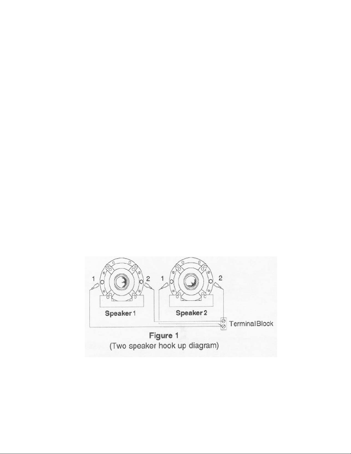
NOTE: When two speakers are connected to the same siren amplifier, the speakers must be connected in parallel and
phased correctly. See Figure 1.
WARNING: Do not attempt to solder wires to studs, as serious damage to driver will result.
4. Install paper washer #6 and rubber washer #7 (2) in speaker tip assembly #8 and set aside.
5. Install steel washer #2, paper washer #3, plastic horn #4 or #5, and second paper washer #3 over the tip of
the driver. See figure 2.
NOTE: The slots/holes in the plastic horn should be on the bottom as are the slots in the mounting bracket.
6. Thread the tip assembly with washers installed onto the end of the driver and tighten by hand. The speaker
must be mounted with two screws through the slots/holes in the plastic horn. The siren speaker assembly is
now complete.
3
Page 4

!
W ARNING!
All devices should be mounted in accordance with the manufacturer’s instructions and
securely fastened to vehicle elements of sufficient strength to withstand the forces applied to
the device. Ease of operation and convenience to the operator should be the prime
consideration when mounting the siren and controls. Adjust the mounting angle to allow
maximum operator visibility.
Do not mount the Control Head Module in a location that will obstruct the drivers view.
Mount the microphone clip in a convenient location to allow the operator easy access.
Devices should be mounted only in locations that conform to their SAE identification code as
described in SAE Standard J 1849. For example, electronics designed for interior mounting
should not be placed underhood, etc. Controls should be placed within convenient reach* of
the driver or if intended for two person operation the driver and/or passenger. In some
vehicles, multiple control switches and/or using methods such as “horn ring transfer” which
utilizes the vehicle horn switch to toggle between siren tones may be necessary for
convenient operation from two positions.
* Convenient reach is defined as the ability of the operator of the siren systems to manipulate
the controls from his normal driving/riding position without excessive movement away from
the seat back or loss of eye contact with the roadway.
The user should install a fuse sized to approximately 125% of the maximum Amp cap acity in
the supply line to protect against short circuits. For example, a 30 Amp fuse should carry a
maximum of 24 Amp s. DO NOT USE 1/4" DIAMETER GLASS FUSES AS THEY ARE NOT
SUIT ABLE FOR CONTINUOUS DUTY IN SIZES ABOVE 15 AMPS. Circuit breakers are
very sensitive to high temperatures and will “false trip” when mounted in hot environments or
operated close to their capacity .
!
W ARNING!
CONNECTION OF A 58 WATT SPEAKER TO THE 100 W ATT TERMINAL WILL CAUSE
THE SPEAKER TO BURN OUT, AND WILL VOID THE SPEAKER W ARRANTY!
The sound projecting opening should be pointed forward, parallel to the ground, and not
obstructed or muffled by structural components of the vehicle. Concealed or under-hood
mountings in some cases will result in a dramatic reduction in performance. To minimize
this reduction, mount the speaker so the sound emitted is projected directly forward and
obstruction by vehicle components such as hoses, brackets, grille, etc. is minimized.
Electromechanical sirens and electronic siren speakers should be mounted as far from the
occupants as possible using acoustically insulated compartment s and isolation mountings
to minimize the transmission of sound into the vehicle. It may be helpful to mount the device
on the front bumper, engine cowl or fender; heavily insulate the p assenger comp artment;
and operate the siren only with the windows closed.
Each of these approaches may cause significant operational problems, including loss of
siren performance from road slush, increased likelihood of damage to the siren in minor
collisions, and the inability to hear the sirens on other emergency vehicles. APPROPRIATE
TRAINING OF VEHICLE OPERA TORS IS RECOMMENDED TO ALERT THEM TO THESE
PROBLEMS AND MINIMIZE THE EFFECT OF THESE PROBLEMS DURING
OPERATIONS.
4
Page 5

100 Watt S peaker Part s List:
Ref No. Description Part No. Qty.
1 Driver, 100 Watt (Atlas) T03470 1
Driver 100 Watt (Mitek) T11261 1
2 Washer #8, Steel T00702 1
3 Washer, Paper T00701 2
4 Plastic Horn, PSE Models S01015 1
5 Plastic Horn, LP Models S91474 1
6 Washer, Paper T00703 1
7 Washer, Rubber T00704 2
8 Re-entrant Tip Assy (Atlas) T00626 1
9 Mounting Bracket, 100Watt S85162 1
10 1/4-20X1/2" Mounting Bolts T00671 2
Parts NotShown
#8 S.S. Mounting Screws T00243 4
White Terminal Wire T04346 1
Blue Terminal Wire T04347 1
Flat Washer T00154 4
V oice Coil, 100 Watt (Atlas) T00707 1
5
Page 6

NOTES
6
Page 7

NOTES
7
Page 8

WARRANTY
This product was tested and found to be operational at the time of manufacture. Provided
this product is installed and operated in accordance with the manufacturer's recommendations,
CODE3, Inc. guarantees this product for a period of 5 years from the date of purchase or delivery,
whichever is later (does not apply to lamps). Units demonstrated to be defective within the warranty period will be repaired or replaced at the factory service center at no cost.
Use of a lamp or other electrical load of a wattage higher than installed or recommended by
the factory, or use of inappropriate or inadequate wiring or circuit protection causes this warranty to
become void. Failure or destruction of the product resulting from abuse or unusual use and/or
accidents is not covered by this warranty. Use of non-CODE 3 components and assemblies may
cause damage to the system and/or personal injury, and voids all warranties.
CODE 3, Inc. shall in no way be liable for other damages including consequential, indirect or
special damages whether loss is due to negligence or breach of warranty.
CODE 3, INC. MAKES NO OTHER EXPRESS OR IMPLIED WARRANTY INCLUDING,
WITHOUT LIMITATION, WARRANTIES OF FITNESS OR MERCHANTABILITY, WITH RESPECT TO THIS PRODUCT.
PRODUCT RETURNS
In order to provide you with faster service, if you are going to return a product for repair or replacement*, please contact our factory to obtain a Return Goods Authorization Number (RGA number) before
you ship the product to Code 3. Write the RGA number clearly on the package near the mailing label.
Be sure you use sufficient packing materials to avoid damage to the product being returned while in
transit.
*Code 3, Inc. reserves the right to repair or replace product at its discretion and assumes no responsibility or liability for
expenses incurred for the removal and/or reinstallation of products requiring service and/or repair.
NEED HELP? Call our Technical Assistance HOTLINE - (314) 996-2800
St. Louis, Missouri 63114-2029—USA
10986 N. Warson Road
CODE 3, Inc.
www.code3pse.com
Code 3 is a registered trademark of Code 3, Inc. a subsidiary of Public Safety Equipment, Inc.
Revision 5, 10/2006 - Instruction Book Part No. T16201
©1994-2006 CODE 3, Inc. Printed in USA
 Loading...