

Page 1
INSTALLATION
GUIDE
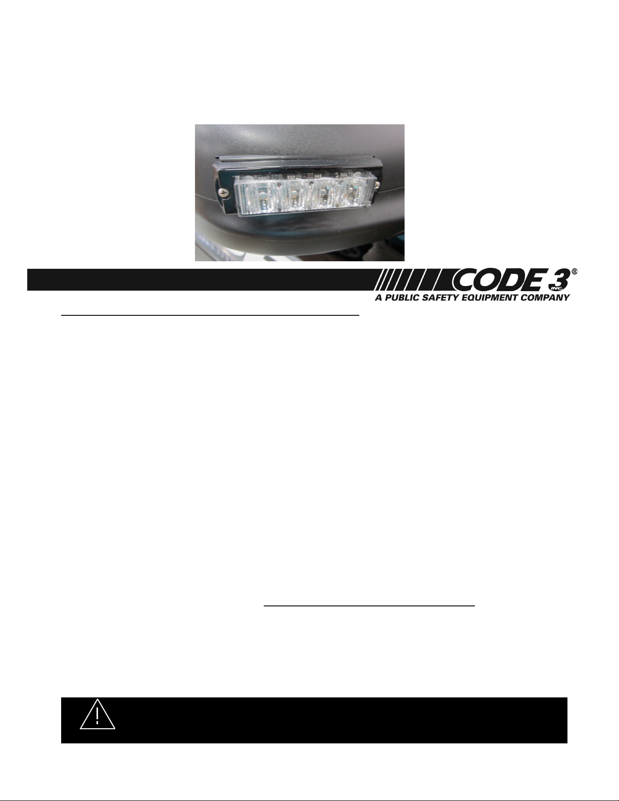
XT4 Side View Mirror Mounting Brackets
Installing the XT4 Side View Mirror Lights:
Step-1. Position the supplied mounting bracket as desired on the vehicles plastic mirror housing to determine the
desired mounting angle and location.
Step-2. Use the mounting bracket as a template to locate and drill holes in the vehicles plastic mirror housing for
the wires and start holes for the mounting screws. Caution: It is advisable to remove the mirror from the hous-
ing to be sure the locations of the drilled holes will not damage the OEM components inside the housing!
a. Drill the start holes for the mounting screws with a 3/32” .0937” diameter drill and drill the wire hole with a
3/8” .375 diameter drill.
Step-3. Install the light head.
a. Hold the smaller gasket against the vehicles plastic mirror housing (This gasket ts just inside the bracket
and its purpose is to hide the wires behind the mounting bracket after the unit is tightened up against the vehicles
mirror housing).
b. Hold the mounting bracket in position against the vehicles plastic mirror housing.
c. Hold the light head gasket in position against the mounting bracket.
d. Feed the light head wires in through the 3/8” hole and into the vehicles plastic mirror housing making sure
they will be accessable from inside the housing to complete the wiring.
e. Hold the light head in position over the assembly.
f. Thread the (2) supplied #6 X 1 ½” long Stainless Steel Phillips Pan Head Sheet Metal Screws through everything and into the start holes in the vehicles plastic mirror housing.
Step-4. Tighten each of the screws a little at a time until they are just tight enough to snug the assembly up against
the vehicles plastic mirror housing. Be careful "DO NOT TO OVER TIGHTEN THE SCREWS" as that could potentially strip out the plastic around the screws.
Step-5. In the nal assembly the mounting bracket is sandwiched between the light head and the vehicles plastic
mirror housing.
Step-6. Complete the wiring as desired! Note: If this is a component included in a CELS Package, see the
CELS-CC Housing Instruction Manual for the remaining wiring connections.
NEED HELP? Call our Technical Assistance HOTLINE - (314) 996-2800
DO NOT APPLY 12 VOLTS DIRECTLY TO THE XT4 LIGHT HEAD WIRES AFTER THE LIGHT HEAD IS
CONNECTED TO THE CELS CC BOX. IF THE XT4 IS A COMPONENT OF THE CELS SYSTEM THE CC BOARD
WARNING!
Code 3®, Inc. 10986 N. Warson Road St. Louis, Missouri 63114-2029—USA Ph. (314) 426-2700 Fax (314) 426-1337 www.code3pse.com
Code 3 is a registered trademark of Code 3, Inc. a Public Safety Equipment Company.
OR THE LIGHT HEADS COULD BE DAMAGED BY APPLYING 12 VOLTS TO THE CC OUTPUTS!.
Revision 0, 08/13 - Instruction Book Part No. T15735 ©2013 Public
Safety Equipment, Inc. Printed in USA
 Loading...