

Page 1
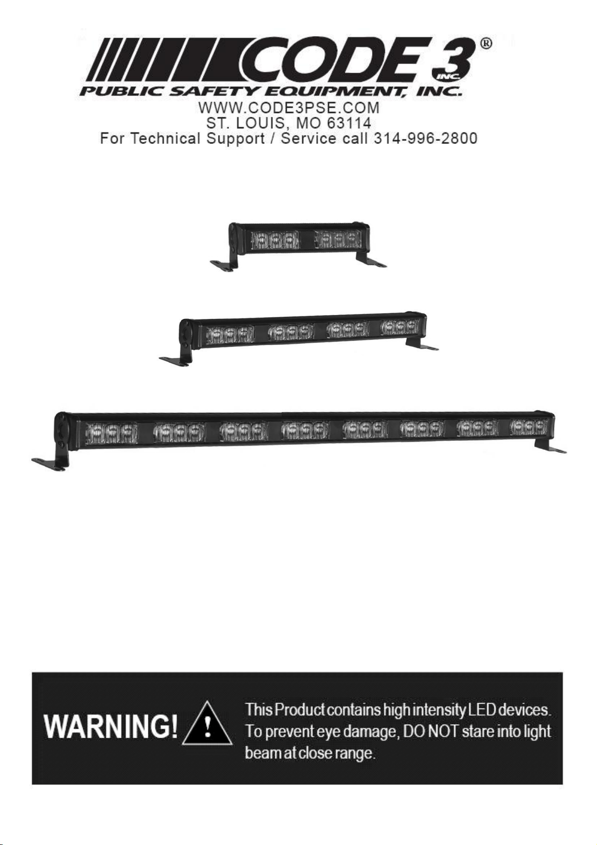
XT302, XT304,XT308 LED WARNING LIGHTS
XT302
XT304
XT308
TABLE OF CONTENTS
Safety Warnings….…………………………………………………….…………..1
Specifications…………………………………………………………………….…1
Mounting……………………………………………………………………………..2
Operation………………………………………………………………………..…...2
Adjustment..…………………………………......…………………...……………..2
Patterns…… ……………………………………………………….………..…..…2,3
Troubleshooting………………………………………………………..…….…….3
Safety Warnings
Page 2
IMPORTANT: Please be sure to check that the product is properly fused. Installing the XT3xx LED
light without the appropriate fuse will void the warranty.
Specifications
XT302 XT304 XT308
Input Voltage 11-30 VDC 11-30 VDC 11-30VDC
Peak Input Current 1 Amp 2 Amp 4 Amp
Output Power 6 W 12 W 24 W
Flash Patterns 22 31 31
Fuse
(customer supplied)
2A 3A 5A
Mounting
Mount the XT3xx LED light using the brackets supplied and user supplied mounting screws.
CAUTION: Be certain that you have selected a mounting location that does not obstruct the driver’s vision and
allows safe operation of the vehicle. Check the chosen mounting location to ensure that the vehicle’s structure
and material is adequate to support the weight of your light.
Operation
Install the Function Switch (User Supplied) to the Warning Light. The patterns are changed
with the BLUE wire. To advance to the next pattern, apply BLUE to the BLACK wire for less than
1 second. To cycle backwards to previous patterns, apply BLUE to the BLACK wire for 1-3 second.
To reset to the factory default pattern, apply BLUE to the BLACK wire for 3-5 second. To turn off
power, apply BLUE to the BLACK wire for more 5 second.
1
Page 3

ON/OFF/PATTERN SELECT BLUE WIRE :
MODEL
PUSH TIMES
0 ~ 1 sec.
1 ~ 3 sec.
3 ~ 5 sec.
5 ~ sec. OFF
XT302, XT304, XT308
FUNCTION
NEXT PATTERN / ON
PREVIOUS PATTERN
FACTORY DEFAULT
Operation Environment
Ambient Temperature: -10 to 45℃
Relative Humidity: 10 to 85%, non-condensing
Adjustment
After the XT302 or XT304 or XT308 light is securely installed, loosen the adjusting screws located on each end and tilt the
light to the desired angle. Then tighten the screws. Turn the XT3xx LED light on and check the light from the front or rear
of the vehicle, through the window, to ensure that it is at the most desirable angle, and that the light is not impeded by any
obstacles and/or window tinting.
Patterns
Model XT302 alt=alternation sim=simulataneous
P1 five flash alt
P2 five flash sim p1
P3 five flash sim p2
P4 quad flash alt
P5 quad flash sim p1
P6 quad flash sim p2
P7 single flash 75 alt
P8 single flash 75 sim p1
P9 single flash 75 sim p2
P10 single flash 375 alt
P11 single flash 375 sim p1
Model XT-304,XT-308 alt=alternation sim=simulataneous
P1 five flash alt
P2 five flash in-out
P3 five flash checker board
P4 five flash sim phase1a
P5 five flash sim phase2a
P6 quad flash alt
P7 quad flash in-out
P8 quad flash checker board
P9 quad flash sim p1
P10 quad flash sim p2
P11 single flash 75 alt
P12 single flash 75 in-out
P13 single flash 75 checker board
P14 single flash 75 sim p1
P15 single flash 75 sim p2
P16 single flash 375 alt
P12 single flash 375 sim p2
P13 quad-squad flash alt
P14 quad-squad flash sim
P15 modulation flash alt
P16 modulation flash sim
P17 quad-squad scan
P18 steadyburn with 5 single and single pop
P19 steadyburn - 5 single
P20 steady burn
P21 Cycle Flash(Demo mode)- AUTORUN
P22 turn off
P17 single flash 375 in-out
P18 single flash 375 checker board
P19 single flash 375 sim p1
P20 single flash 375 sim p2
P21 modulation flash alt
P22 modulation flash in-out
P23 modulation flash chack board
P24 modulation flash sim only
P25 quad-squad flash alt
P26 single-double 60
P27 single-double 90
P28 single-double 120
P29 Cycle Flash(Demo mode)- AUTORUN
P30 steady burn
P31 turn off
Troubleshooting
The XT302, XT304, XT308 have been factory tested and approved. If the light fails to work, check the following
1. Press the Function switch (User Supplied) to be sure the “Off” pattern is not selected.
2. Remove the fuse from the vehicle fuse box and check to see if it has blown.
2
 Loading...