

Page 1
WWW.CODE3PSE.COM
ST LOUIS, MO 63114
For Technical Support/Service Call (314)-996-2700
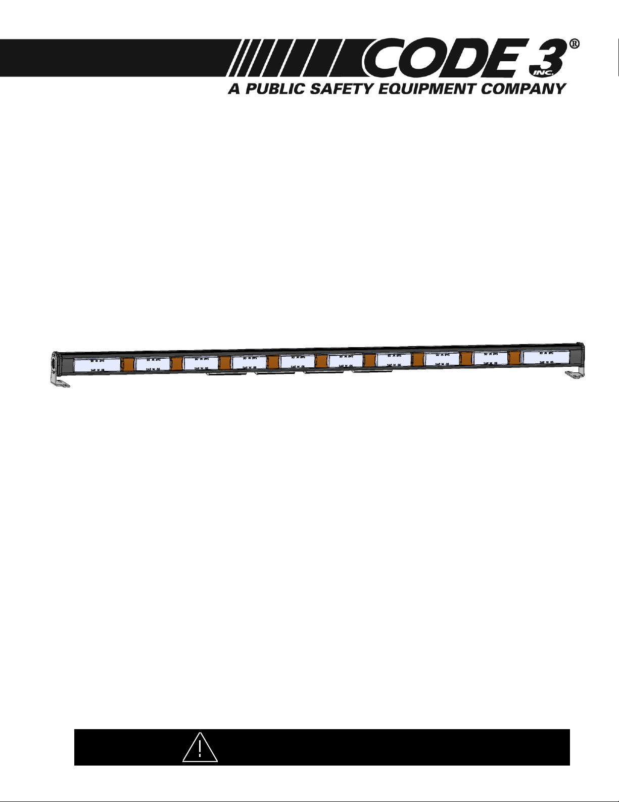
XT310AS LED WARNING LIGHTS
TABLE OF CONTENTS
Safety Warnings…………………………………………………………………………......1
Specications………………………………………………………………………………...2
Mounting………………………………………………………………………………….…..2
Wiring...………………………………………………………………….….……………......3
Flash Patterns..………………......…………......…………………………...……..……….4
Troubleshooting………………………………………………………………………...……4
Safety Warnings
WARNING!
This Product contains high intensity TriCore® devices. To prevent eye
damage, DO NOT stare into light beam at close range.
Page 2
WARNING!
The use of this or any warning device does not ensure that all drivers can or will observe or react to an
emergency warning signal. Never take the right-of-way for granted. It is your responsibility to be sure you can
proceed safely before entering an intersection, driving against trafc, responding at a high rate of speed, or
walking on or around trafc lanes. The effectiveness of this warning device is highly dependent upon correct
mounting and wiring. Read and follow the manufacturer’s instructions before installing or using this device. The
vehicle operator should insure daily that all features of the device operate correctly. In use, the vehicle operator
should insure the projection of the warning signal is not blocked by vehicle components (i.e.: open trunks or
compartment doors), people, vehicles, or other obstructions. This equipment is intended for use by authorized
personnel only. It is the user’s responsibility to understand and obey all laws regarding emergency warning
devices. The user should check all applicable city, state and federal laws and regulations. Code 3, Inc., assumes
no liability for any loss resulting from the use of this warning device. Proper installation is vital to the performance
of this warning device and the safe operation of the emergency vehicle. It is important to recognize that the
operator of the emergency vehicle is under psychological and physiological stress caused by the emergency
situation. The warning device should be installed in such a manner as to: A) Not reduce the output performance
of the system, B) Place the controls within convenient reach of the operator so that he can operate the system
without losing eye contact with the roadway. Emergency warning devices often require high electrical voltages
and/or currents. Properly protect and use caution around live electrical connections. Grounding or shorting of
electrical connections can cause high current arcing, which can cause personal injury and/or severe vehicle
damage, including re. Any electronic device may create or be affected by electromagnetic interference. After
installation of any electronic device operate all equipment simultaneously to insure that operation is free of
interference. Never power emergency warning equipment from the same circuit or share the same grounding
circuit with radio communication equipment. All devices should be mounted in accordance with the manufacturer's
instructions and securely fastened to vehicle elements of sufcient strength to withstand the forces applied to the
device. Driver and/or passenger air bags (SRS) will affect the way equipment should be mounted. This device
should be mounted by permanent installation and within the zones specied by the vehicle manufacturer, if any.
Any device mounted in the deployment area of an air bag will damage or reduce the effectiveness of the air
bag and may damage or dislodge the device. Installer must be sure that this device, its mounting hardware and
electrical supply wiring does not interfere with the air bag or the SRS wiring or sensors. Mounting the unit inside
the vehicle by a method other than permanent installation is not recommended as unit may become dislodged
during swerving, sudden braking or collision. Failure to follow instructions can result in personal injury. PROPER
INSTALLATION COMBINED WITH OPERATOR TRAINING IN THE PROPER USE OF EMERGENCY WARNING
DEVICES IS ESSENTIAL TO INSURE THE SAFETY OF EMERGENCY PERSONNEL AND THE PUBLIC.
IMPORTANT: Please be sure to check that the product is properly fused. Installing the XT310 LED light
without the appropriate fuse will void the warranty.
Specications XT310AS
Input Voltage....................................................................................11-30VDC
Peak Input Current..............................................................................4 Amp
Output Power.......................................................................................24 W
Flash Patterns.......................................................................................32
Fuse(User supplied)..............................................................................5A
STORAGE TEMPERATURE RANGE..............................................- 40 to + 90 Degrees C
Mounting
Mount the XT310 LED light using the brackets supplied and user supplied mounting screws.
CAUTION: Be certain that you have selected a mounting location that does not obstruct the driver’s vision and
allows safe operation of the vehicle. Check the chosen mounting location to ensure that the vehicle’s structure
and material is adequate to support the weight of your light.
2
Page 3

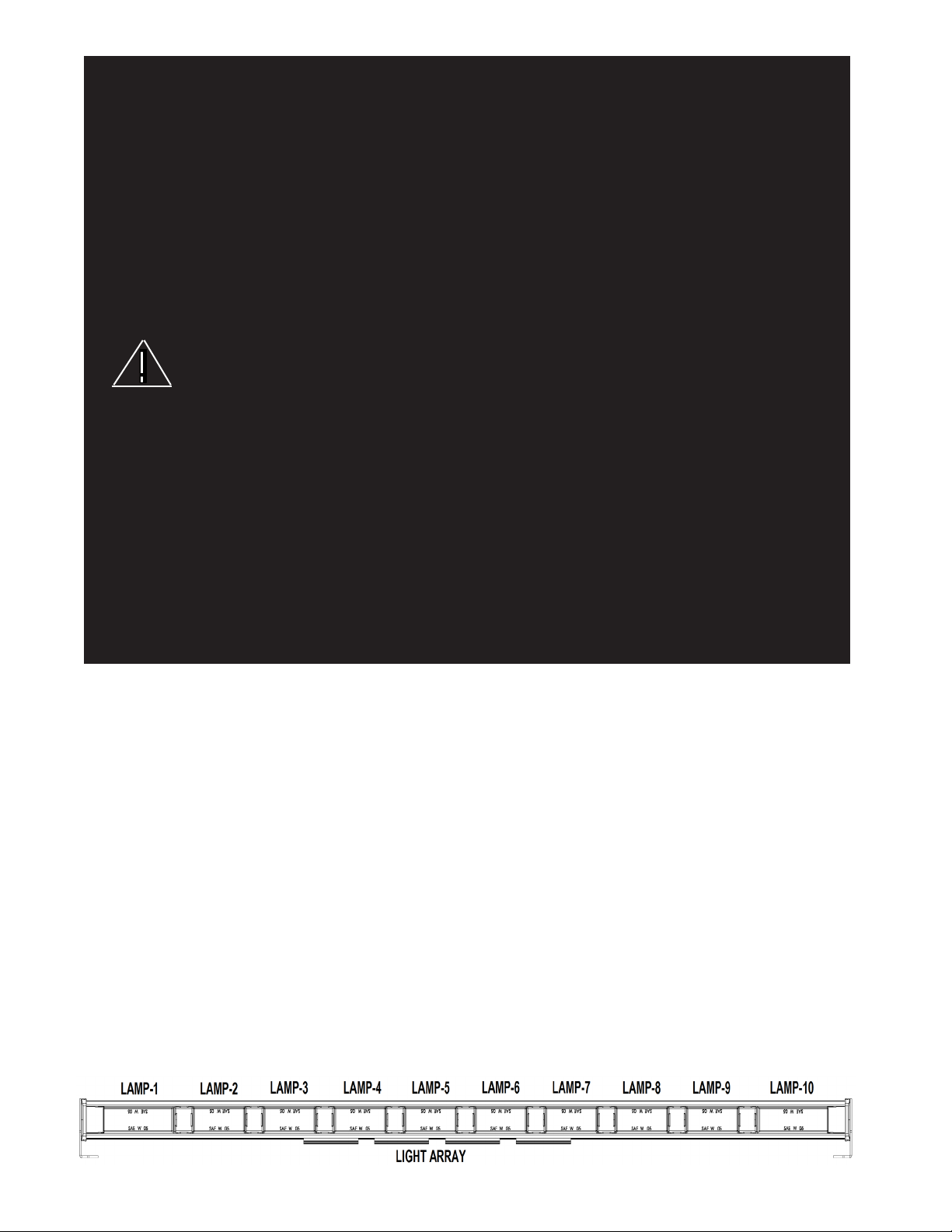
Wiring - XT310 Arrow Stick LED WARNING LIGHTS - OPERATION
Red wire to + 12V Power Input---Black wire to GND
OFF Mode Red wire to +12V OFF Mode - all LED's will be Off
Black wire to GND
Dim Mode Operation: Brightness will be reduced
Connect Green Wire to + Power (+12V)
Dim mode will operate In any mode
Warning Mode Operation: Left end and right end
(Only left end & Connect Blue wire to + Power (+12V) light heads will ash
right end light heads Pattern change operation: Flash pattern change
2 total will ash Touch Brown wire to Blue wire to + Power (+12V) 10 different ash patterns
8 amber light heads (for less than 3 seconds)
will not ash)
Warning Mode Operation 1 : Preset in Warning Mode 1
10 light heads Connect Orange wire to + Power (+12V) Emergency Flashing Mode 1
Operation 2: Preset in Warning Mode 2
Connect Orange wire + Blue wireto + Power (+12V) Emergency Flashing Mode 2
Pattern change operation: Warning Mode ash
Touch Brown wire to + Power (+12V) pattern change.
(For less than 3 seconds)
Memorized preset Warning Mode:
Operation as shown below
Touch Brown wire + Orange wire to + Power (+12V) Memorized preset
(longer than 3 seconds) Warning Mode 1
Touch Brown wire to Blue + Orange wire to + Power (+12V) Memorized preset
(For longer than 3 seconds) Warning Mode 2
Trafc Direction Light Connect Red/White wire to + Power (+12V) Preset in Trafc Direction
(Middle 8 Amber light Mode 1 Left Directional Arrow
heads) Connect Brown/White wire to + Power (+12V) Preset in Trafc Direction
Mode 2 Right Directional Arrow
Connect Red/White wire + Brown/White wire Preset in Trafc Direction
to + Power (+12V) Mode 3 Center outward Arrow
Pattern change operation: Trafc Direction ash
Touch Brown wire to + Power (+12V) pattern change
(For less than 3 seconds)
Memorized preset trafc direction Mode:
Operation as shown below
Touch Brown wire + Red/White wire Memorized preset
to + Power (+12V) Trafc direction Mode 1
(For longer than 3 seconds)
Touch Brown wire + Brown/White wire to + Power (+12V) Memorized preset
(For longer than 3 seconds) Trafc direction Mode 2
Touch Brown wire + Red/White wire + Memorized preset
Brown/White wire to + Power (+12V) Trafc direction Mode 3
(For longer than 3 seconds)
Warining + Trafc Connect Red/White wire + Brown/White wire Warning + Trafc direction
Direction Mode to + Power (+12V) Flash mode
(trafc direction 8 Connect Orange wire + Blue Wire to + Power (+12V)
amber with 2 end Touch Brown wire + Red/White wire + Brown/White Flash Pattern changed
warning light heads) to + Power (+12V)
(For less than 3 seconds)
Touch Brown wire + Red/White wire + Brown/White
to + Power (+12V)
(For longer than 3 seconds) Memorized the pattern
3
Page 4

XT310AS FLASH PATTERNS
WARNING FLASH PATTERNS
1 OFF
2 INBOARD OUTBOARD(single ash)
3 LEFT RIGHT(single ash)
4 ALTERNATE(single ash)
5 INBOARD OUTBOARD(Double ash)
6 LEFT RIGHT(Double ash)
7 ALTERNATE(Double ash)
8 INBOARD OUTBOARD(Quad Flash)
9 LEFT RIGHT(Quad Flash)
10 ALTERNATE(Quad Flash)
11 SINGLE OUTBOARD
12 DOUBLE OUTBOARD
13 SINGLE INBOARD
14 DOUBLE INBOARD
15 TRIPLE INBOARD
16 SWEEP
17 CYCLE FLASH
TRAFFIC DIRECTION MODES
1 Right
2 Left
3 Center-Out
4 Right Fast
5 Left Fast
6 Center-Out Fast
7 SINGLE INBOARD-1
8 SINGLE INBOARD-1 Fast
9 SINGLE INBOARD Full-1
10 SINGLE INBOARD Full-1 Fast
END HEAD FLASH PATTERNS (60 fpm)
1 Single Flash Alternate
2 Double Flash Alternate
3 Three Flash Alternate
4 Quad Flash Alternate
5 Five Flash Alternate
6 Single Flash Simultaneous
7 Double Flash Simultaneous
8 Three Flash Simultaneous
9 Quad Flash Simultaneous
10 Five Flash Simultaneous
Operation Environment
Ambient Temperature: -10 to +45 degrees C
Relative Humidity: 10 to 85%, non-condensing
Adjustment
After the XT310AS light is securely installed, loosen the adjusting screws located on each end and tilt the light
to the desired angle. Then tighten the screws. Turn the XT310AS LED light on and check the light from the front
or rear of the vehicle, through the window, to ensure that it is at the most desirable angle, and that the light is
not impeded by any obstacles and/or window tinting.
Troubleshooting
The XT310AS have been factory tested and approved. If the light fails to work, check the following:
1. Press the Function Switch (User Supplied) to be sure the “Off” pattern is not selected.
2. Remove the fuse from the vehicle fuse box and check to see if it has blown.
4
Page 5

NOTES:
5
Page 6

NOTES:
6
Page 7

NOTES:
7
Page 8

WARRANTY
This product with TriCore® Technology was tested and found to be operational at the time of manufacture.
Provided this product is installed and operated in accordance with the manufacturer's recommendations, Code
3®, Inc. warrants all parts and components (with the exception of all incandescent and halogen bulbs) of the
product to be free of defects in material and workmanship for a period of one (1) year and TriCore light heads
for a period of ve (5) years from the date of purchase. This Warranty excludes normal wear & tear. Units
demonstrated to be defective within the warranty period will be repaired or replaced at the factory service center
at no cost. Code 3, Inc. will return the repaired product with transportation cost prepaid. Code 3, Inc. assumes
no liability for expenses incurred in the packaging, handling, and shipping of the product to the Factory Technical
Service Department for repair. For in-warranty product return authorization, questions regarding product warranty
coverage or questions regarding out-of-warranty repair quotes, contact the Factory Technical Service Department.
The TriCore light heads are sealed as part of the quality control process. This Warranty is void if, in the
judgment of Code 3, Inc. (1) an attempt has been made to break the light head seal or repair the light head,
and/or (2) the product has been used with inappropriate or inadequate wiring or circuit protection, and/or (3)
the product has failed as a result of abuse or unusual use and/or accidents.
CODE 3, INC. SHALL IN NO WAY BE LIABLE FOR ANY OTHER DAMAGES RELATING TO THE
PRODUCT INCLUDING BUT NOT LIMITED TO CONSEQUENTIAL, INCIDENTAL, INDIRECT OR SPECIAL DAMAGES OR LOST PROFITS OR REVENUE; NOR ANY EXPENSES INCURRED IN THE REMOVAL AND/OR RE-INSTALLATION OF PRODUCTS REQUIRING SERVICE AND/OR REPAIR.
EXCEPT AS SET FORTH ABOVE, CODE 3, INC. MAKES NO OTHER EXPRESS OR IMPLIED
WARRANTIES WHATSOEVER, INCLUDING, WITHOUT LIMITATION, WARRANTIES OF FITNESS FOR A
PARTICULAR PURPOSE OR MERCHANTABILITY, WITH RESPECT TO THIS PRODUCT.
NEED HELP? Call our Technical Assistance HOT LINE - (314) 996-2800
PRODUCT RETURNS
If a product must be returned for repair or replacement*, please contact our factory to obtain a Return
Goods Authorization Number (RGA number) before you ship the product to Code 3, Inc. Write the RGA number
clearly on the package near the mailing label. Be sure you use sufcient packing materials to avoid damage to
the product being returned while in transit.
*Code 3, Inc. reserves the right to repair or replace at its discretion. Code 3, Inc. assumes no responsibility or liability for expenses incurred for the removal and /or
reinstallation of products requiring service and/or repair.; nor for the packaging, handling, and shipping: nor for the handling of products returned to sender after the service has been
rendered.
St. Louis, Missouri 63114-2029—USA
Ph. (314) 426-2700 Fax (314) 426-1337
10986 N. Warson Road
www.code3pse.com
Code 3®, Inc.
Code 3 is a registered trademark of Code 3, Inc. a subsidiary of Public Safety Equipment, Inc.
Revision 0, 09/12 - Instruction Book Part No. T15549
©2012 Public Safety Equipment, Inc. Printed in USA
8
 Loading...