

Page 1
INSTALLATION
& OPERATION
MANUAL
WingMan™
Standard - Torus Version
WingMan TS™
Interior Lighting System
for Impala, Caprice, and Charger
CONTENTS:
Introduction............................................................................2
Unpacking & Pre-Installation....................................................2
Installation & Mounting.........................................................3-7
Wiring Diagram & Instructions..................................................8
NarrowStik Wiring Diagram.......................................................9
LED Flash Pattern Selection...................................................10
Troubleshooting..................................................................10
Exploded View & Parts List..........................................................11
Warranty................................................................................12
For future reference record your product's serial no. here __________________________________________
IMPORTANT:
Read all instructions and warnings before installing and using.
This manual must be delivered to the end user of this equipment.
INSTALLER:
Page 2

Introduction
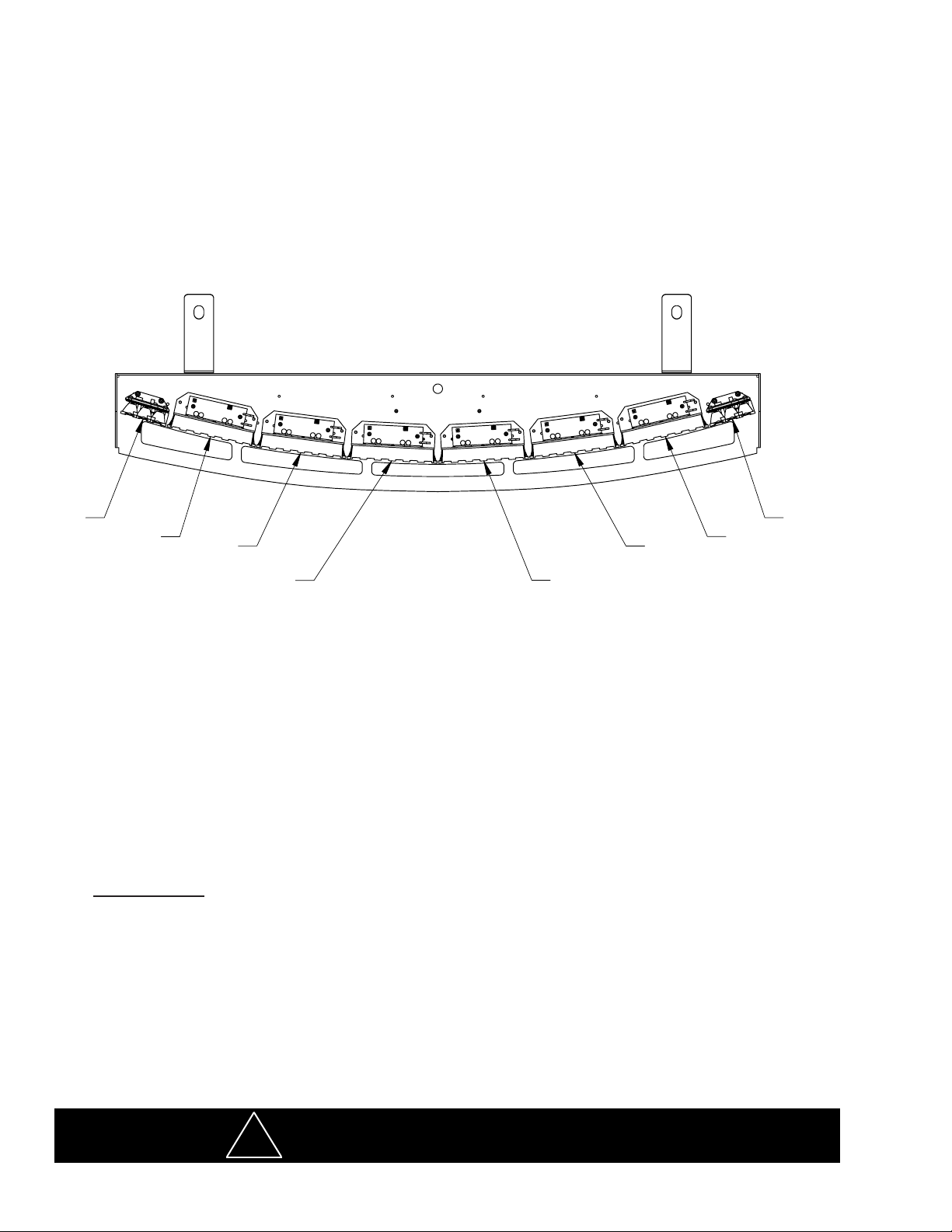
The WingMan™ is an interior lighting system that ts in the rear deck area behind the rear seat. The WingMan has room for up to eight light
heads.
Product Features
LED lighthead options: Red, Blue, Amber; Flashing or Steady Burn Control
LED lighthead types: 3LED Torus and 6LED Torus
The use of this or any warning device does not ensure that all drivers can or will observe or react to an
emergency warning signal. Never take the right-of-way for granted. It is your responsibility to be sure you can
proceed safely before entering an intersection, driving against trafc, responding at a high rate of speed, or
walking on or around trafc lanes. The effectiveness of this warning device is highly dependent upon correct
mounting and wiring. Read and follow the manufacturer’s instructions before installing or using this device. The
vehicle operator should insure daily that all features of the device operate correctly. In use, the vehicle operator
should insure the projection of the warning signal is not blocked by vehicle components (i.e.: open trunks or
compartment doors), people, vehicles, or other obstructions. This equipment is intended for use by authorized
personnel only. It is the user’s responsibility to understand and obey all laws regarding emergency warning
devices. The user should check all applicable city, state and federal laws and regulations. Code 3, Inc., assumes
no liability for any loss resulting from the use of this warning device. Proper installation is vital to the performance
of this warning device and the safe operation of the emergency vehicle. It is important to recognize that the
operator of the emergency vehicle is under psychological and physiological stress caused by the emergency
situation. The warning device should be installed in such a manner as to: A) Not reduce the output performance
of the system, B) Place the controls within convenient reach of the operator so that he can operate the system
without losing eye contact with the roadway. Emergency warning devices often require high electrical voltages
and/or currents. Properly protect and use caution around live electrical connections. Grounding or shorting of
electrical connections can cause high current arcing, which can cause personal injury and/or severe vehicle
WARNING!
damage, including re. Any electronic device may create or be affected by electromagnetic interference. After
installation of any electronic device operate all equipment simultaneously to insure that operation is free of
interference. Never power emergency warning equipment from the same circuit or share the same grounding
circuit with radio communication equipment. All devices should be mounted in accordance with the manufacturer's
instructions and securely fastened to vehicle elements of sufcient strength to withstand the forces applied to the
device. Driver and/or passenger air bags (SRS) will affect the way equipment should be mounted. This device
should be mounted by permanent installation and within the zones specied by the vehicle manufacturer, if any.
Any device mounted in the deployment area of an air bag will damage or reduce the effectiveness of the air
bag and may damage or dislodge the device. Installer must be sure that this device, its mounting hardware and
electrical supply wiring does not interfere with the air bag or the SRS wiring or sensors. Mounting the unit inside
the vehicle by a method other than permanent installation is not recommended as unit may become dislodged
during swerving, sudden braking or collision. Failure to follow instructions can result in personal injury. PROPER
INSTALLATION COMBINED WITH OPERATOR TRAINING IN THE PROPER USE OF EMERGENCY WARNING
DEVICES IS ESSENTIAL TO INSURE THE SAFETY OF EMERGENCY PERSONNEL AND THE PUBLIC.
Unpacking & Pre-installation
Carefully remove the WingMan and place it on a at surface, taking care not to scratch the lenses or damage the cable coming out of the
top. Examine the unit for transit damage, broken lamps, etc. Report any damage to the carrier and keep the shipping carton.
Standard light bars are built to operate on 12 volt D.C. negative ground (earth) vehicles. If you have an electrical system other than 12
volt D.C. negative ground (earth), and have not ordered a specially wired light bar, contact the factory for instructions.
Test the unit before installation. To test, touch the black wire to the ground (earth) and the other wires to +12 volts D.C., in accordance
with the instructions attached to the cable (an automotive battery is preferable for this test). A battery charger may be used, but note that
some electronic options may not operate normally when powered by a battery charger. If problems occur at this point, contact the factory.
Note: Before beginning the installation process, be absolutely certain
that the Light Bar functions as desired (See page 8 for options)!
WARNING!
Utilizing non-factory supplied screws and/or mounting brackets and/or the improper
number of screws may result in loss of warranty coverage on the equipment.
Mounting Hardware - All mounting hardware is included. There are two brackets and two mounting plates used to
mount the WingMan™ to the vehicle. These are discussed in detail later.
2
Page 3
Installation Instructions per Vehicle Models
2011+ Chevy Caprice
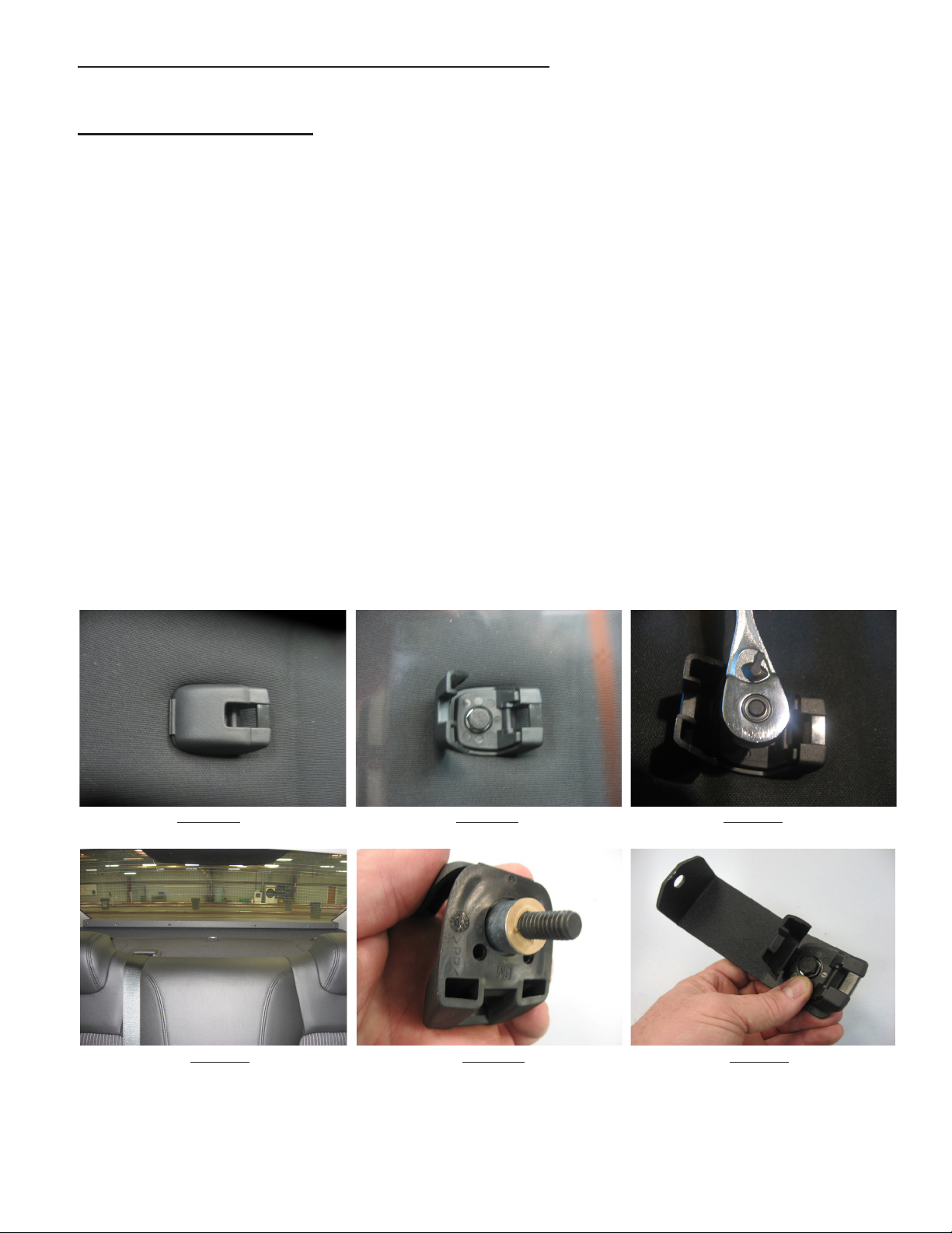
Step 1 Locate the vehicle's Driver and Passenger outer plastic child restraint brackets in the rear package tray area behind the rear seat and
open the hinged bolt covers (see Figures 1 and 2).
Step 2 Remove the 8mm child restraint mounting bolts with a 1/2" SAE or 13mm metric wrench (see Figure 3). Do not remove the steel spacer
and the cardboard washer from the brackets.
Step 3 Position the WingMan in the rear package tray area (see Figure 4) to determine the desired routing of the cable into the trunk or
where ever the nal location of the cable is to be. Note: The best and safest cable routing is to drill a clearance hole for the cable directly
through the sheet metal and the interior fabric of the package tray area from inside the trunk of the vehicle directly in line with the
cable exit of the WingMan. This keeps the cable out of a passengers reach Note: Move the WingMan out of the way temporarily and
make sure any OEM wiring is out of the way so you don't damage the WingMan or the wiring when drilling the cable clearance hole!
Route the cable through the hole, pull the slack out of the cable, and reposition the WingMan before going to the next step.
Step 4 Push the steel spacer & the cardboard washer down tight against the vehicle's plastic child restraint brackets as shown in Figure 5.
Step 6 Position the vehicle's plastic child restraint brackets on the supplied WingMan Mounting Brackets as shown in Figure 6.
Step 7 Position the WingMan Mounting Brackets with the vehicle's plastic child restraint brackets and thread the vehicle's 8mm child restraint
bolt back into the existing hole in the vehicle as shown in Figure 7. Leave the bolts slightly loose at this time.
Step 8 Thread the supplied 1/4"-20 screws and internal tooth lock washers through the slots in the WingMan Mounting Brackets and into the
WingMan's Outer Panel as shown in Figure 8. Thread the screw in until there is very little slack between the WingMan Mounting Brackets and
the WingMan Outer Panel but do not tighten the screws at this time.
Step-9 Center the WingMan in the rear window while pushing it back into position to seal the gasket against the rear window glass. Tighten
the vehicle's 8mm child restraint bolt with a 1/2" SAE or 13mm metric wrench as (See Figure 9).
Step-10 Tighten the 1/4"-20 screws with a phillips screwdriver as shown in Figure 10.
Step-11 Snap the hinged bolt covers closed on the vehicle's plastic child restraint brackets (See Figure 11).
FIGURE 1 FIGURE 2 FIGURE 3
FIGURE 4 FIGURE 5 FIGURE 6
2011+ Chevy Caprice Installation continued on next page.
3
Page 4
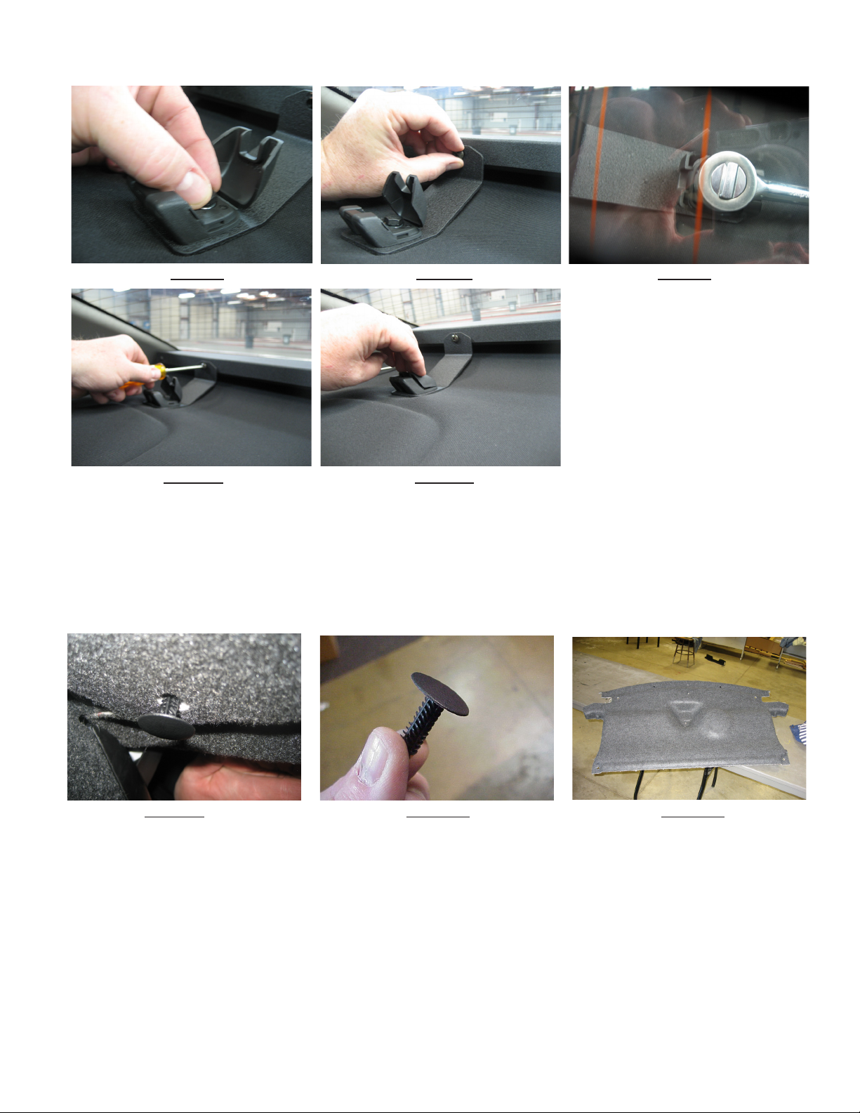
FIGURE 7 FIGURE 8 FIGURE 9
FIGURE 10 FIGURE 11
2011+ DODGE CHARGER
Installation Instructions
Step 1 Lying inside the trunk of the vehicle facing up, look up at the inner roof of the trunk. Locate and remove the (6) Christmas Tree Fasteners (see
Figures 12 & 13) which hold the ber upper trunk liner in place. Remove the ber trunk liner and set it aside (see Figure 14).
FIGURE 12 FIGURE 13 FIGURE 14
Step 2 Position the WingMan in the rear package tray area (see Figure 15) to determine the desired routing of the cable into the trunk or where ever
the nal location of the cable is to be. Note: The best and safest cable routing is to drill a clearance hole for the cable directly through the sheet
metal and the interior fabric of the package tray area from inside the trunk of the vehicle directly in line with the cable exit of the WingMan.
This keeps the cable out of a passengers reach Note: Move the WingMan out of the way temporarily and make sure any OEM wiring is out
of the way so you don't damage the WingMan or the wiring when drilling the cable clearance hole! Route the cable through the hole, pull the
slack out of the cable, and reposition the WingMan before going to the next step.
Step 3 Remove the (2) outer plastic child restraint covers (see Figure 16). Note: If it is desired to retain the child restraint covers they will need to
be trimmed to clear the WingMan's Mounting Brackets after it is installed, other wise discard them.
Step 4 Position the Pemserted WingMan Mounting Brackets in the rear area of the child restraint pockets and line up the threaded hole in the WingMan
Mounting Bracket with the existing holes in the Dodge Charger's Sheetmetal (see Figure 17). Note: One of the tabs on the Mounting Bracket is
shorter than the other. The tab that is the shorter of the two goes into the child restraint pocket. If you have the bracket in backwards the
mounting hole will not line up with the existing hole in the vehicle's sheet metal.
4
Page 5

2011+ Dodge Charger continued
Step 5 From inside the trunk of the vehicle, slip a supplied 1/4" internal tooth lock washer onto a supplied 1/4"-20 X 5/8" Phillips Pan Head Machine
Screw and thread the screw through the existing mounting holes in the child restraint area and into the WingMan's Pemserted Mounting Bracket (see
Figure 18). Repeat this step for both sides of the car. Note: It is helpful to have an assistant hold the WingMan's Mounting Bracket to prevent
movement while you are threading the screws in.
Step 6 Slip a supplied 1/4" internal tooth lock washer onto a supplied Black Zinc Plated 1/4"-20 X 1/2" Phillips Pan Head Machine Screw, Position the
slotted WingMan Mounting Bracket, and thread the screw through the slot in the slotted WingMan Mounting Bracket and into the previously installed
Pemserted WingMan Mounting Bracket (see Figure 19). Repeat this step for both sides of the car.
Step 7 Slip a supplied 1/4" internal tooth lock washer onto a supplied Black Zinc Plated 1/4"-20 X 1/2" Phillips Pan Head Machine Screw and thread the
screw into the WingMan's outer Panel (see Figure 20). Repeat this step for both sides of the car.
FIGURE 15 FIGURE 16 FIGURE 17
FIGURE 18 FIGURE 19 FIGURE 20
Step 8 From inside the trunk tighten the (2) 1/4"-20 X 5/8" Phillips Pan Head Screws (see Figure 21).
Step 9 Back inside the rear passenger area of the vehicle push the WingMan back tight against the rear window and tighten the (2) 1/4"-20 X
1/2" Black Zinc Plated Phillips Pan Head Screws that fasten the WingMan Mounting Brackets together (see Figure 22).
Step10 Tighten the (2) 1/4"-20 X 1/2" Black Zinc Plated Phillips Pan Head Screws that fasten the WingMan Mounting Brackets to the WingMan
(see Figure 23).
Step11 Reposition the vehicle's fabric upper trunk liner and replace the Christmas Tree Fasteners.
Note: If the Gasket has wavy areas where it contacts the rear window you can press down rmly all along the rear contour on top of
the WingMan as far back as you can reach to allow the gasket to pop back into shape.
Note: As stated in Step-3 if it is desired that you retain the plastic child restraint covers you will have to trim the covers to clear the
WingMan's Mounting Brackets before re installing the covers.
FIGURE 21 FIGURE 22 FIGURE 23
5
Page 6
Installation Instructions per Vehicle (continued)
2006+ Chevy Impala
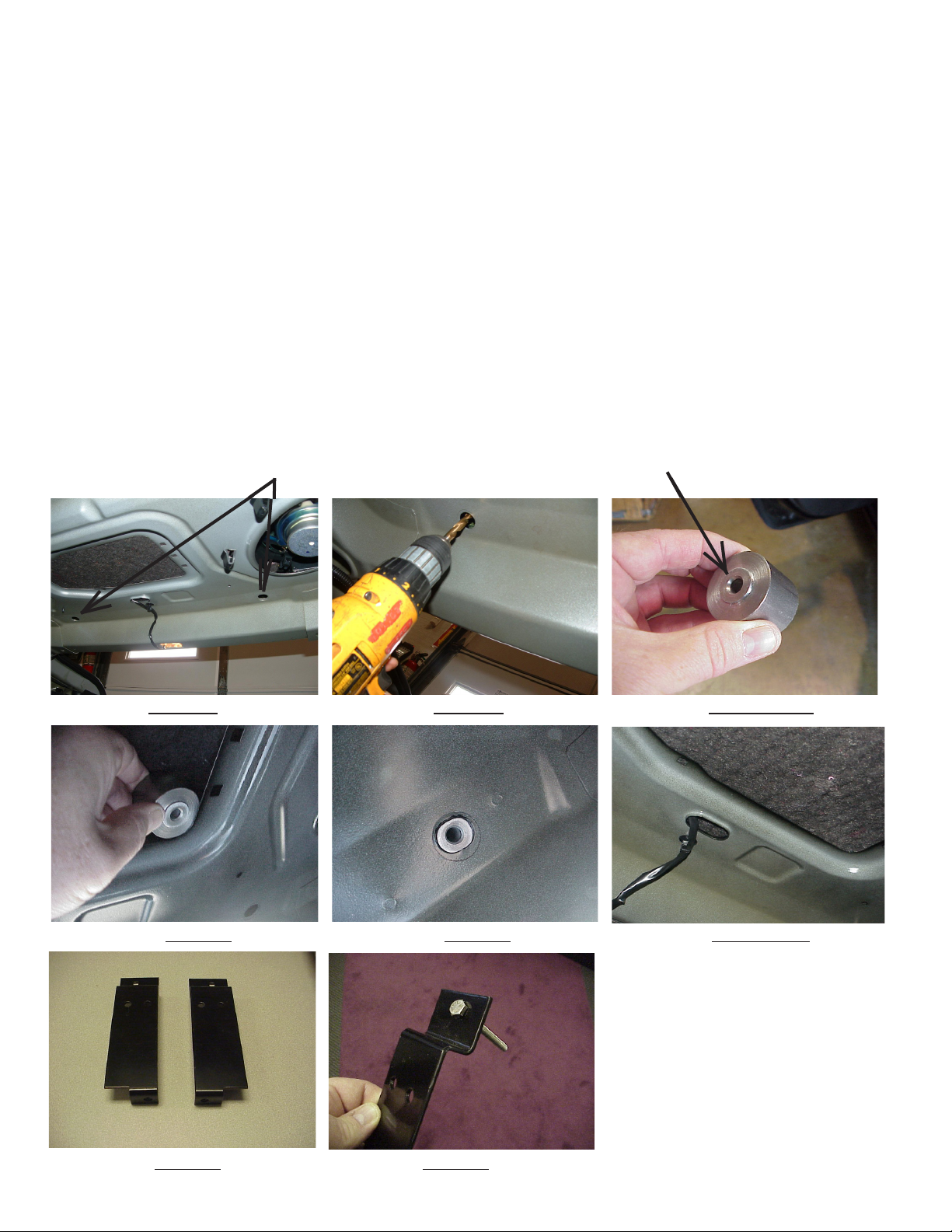
Step 1 From inside the trunk of the Impala, locate the two existing holes in the Impala's rear deck (see Figure 24).
Step 2 Center a 3/8" drill in the existing holes as shown in Figure 25 and drill the two mounting holes through the fabric of the rear deck.
Step 3 Locate the two Mounting Bracket Spacer Bushings from the parts bag (the Mounting Bracket Spacer Bushings are shown in Figure 26).
Push up on the rear deck fabric and starting in the corner of the open area in the center of the rear deck (as shown in Figure 27), push the spacer
into position with the locating shoulder toward the sheet metal and centered in the existing holes in the Impala's rear deck. When the Spacer Bushings are installed correctly they will look as shown in Figure 28.
Step 4 Drill a hole for the cable in the desired location through the rear deck with a 3/8" drill. Inside the oblong hole shown in Figure 29 is a good
location for the cable hole or hole(s). Make sure you don't drill the cable hole too far toward the front of the vehicle. Note: If you are installing a
Double Stack Version of the WingMan with the NarrowStick option you can use a 3/4" diameter drill to create a hole for both cables or
you can drill two 3/8" diameter holes about an inch apart.
Step 5 For Mounting Bracket orientation see Figure 7 showing the WingMan Mounting Brackets. The Passenger Side Mounting Bracket is shown
on the left side of Figure 30 and the Driver's Side Mounting Bracket is shown on the right side of Figure 30 .
Step 6 Insert the 1/4"-20 X 2 1/2" Hex Head Bolts into the square holes in the Mounting Brackets as shown in Figure 31.
___
Two Existing Holes
FIGURE 24 FIGURE 25 FIGURE 26
_
Locating Shoulder
FIGURE 27 FIGURE 28 FIGURE 29
FIGURE 30 FIGURE 31
6
Page 7

Installation Instructions-2006+ Impala-(Cont.)
Step 7 Position the Mounting Brackets with the 1/4"-20 X 2 1/2" Hex Head Bolts over the mounting holes in the rear deck and push the
bolts through the holes and through the Mounting Bracket Spacer Bushings as shown in Figure 32. Make sure the Mounting Brackets are
fairly parallel to each other after they are both in place. Thread a fender washer and a 1/4"-20 locking nut onto each of the bolts from inside
the Impala's trunk. Have an assistant using a wrench from the interior of the Impala keep the bolts from turning and tighten the Hex Nuts as
shown in Figure 33.
Step 8 Feed the WingMan's cable(s) through the cable hole and into the trunk (see Figure 34).
Step 9 Install the WingMan by positioning it over the mounting brackets. You will have to continue feeding the cable through the hole
simultaneously while positioning the bar.
Step 10 As soon as the outer panel mounting plate holes can be lined up with the holes in the mounting brackets
and the mounting holes in the WingMan Bar, insert the (4) supplied 1/4"-20 x 1/2" bolts and internal tooth lock
washers (see Figure 35). Leave the (4) bolts nger tight at this time.
Step 11 Center the lightbar in the rear window of the Impala by using a tape measure and adjust the brackets
and mounting plates so that they line up with each other.
Step 12 Tighten the 1/4"-20 X 1/2" bolts with a phillips screwdriver (see Figure 36).
FIGURE 32 FIGURE 33 FIGURE 34
FIGURE 35 FIGURE 36
The bracket fasteners make excellent hard mounting points for radar guns, video
cameras, etc.
Caution: Drilling into the housing of the light bar could damage wiring or other internal
components.
7
Page 8

Wiring Instructions
It is advisable to leave an extra loop of cable when installing the light bar to allow for future changes or reinstallations.
Connect the black lead to a solid frame ground (earth), preferably the (-) or ground (earth) side of the battery, and the
power wire to the +12V terminal of the battery. Connect the remaining wires as shown on page 8.
Larger wires and tight connections will provide longer service life for components. For high current wires it
is highly recommended that terminal blocks or soldered connections be used with shrink tubing to protect
the connections. Do not use insulation displacement connectors (e.g. 3M® Scotchlock type connectors).
Route wiring using grommets and sealant when passing through compartment walls. Minimize the
number of splices to reduce voltage drop. High ambient temperatures (e.g. under hood) will signicantly
reduce the current carrying capacity of wires, fuses, and circuit breakers. Use "SXL" type wire in engine
compartment. All wiring should conform to the minimum wire size and other recommendations of the
manufacturer and be protected from moving parts and hot surfaces. Looms, grommets, cable ties, and
similar installation hardware should be used to anchor and protect all wiring. Fuses or circuit breakers
WARNING!
should be located as close to the power takeoff points as possible and properly sized to protect the wiring
and devices. Particular attention should be paid to the location and method of making electrical connections
and splices to protect these points from corrosion and loss of conductivity. Ground terminations should
only be made to substantial chassis components, preferably directly to the vehicle battery. The user should
install a fuse sized to approximately 125% of the maximum Amp capacity in the supply line to protect
against short circuits. For example, a 30 Amp fuse should carry a maximum of 24 Amps. DO NOT USE
1/4" DIAMETER GLASS FUSES AS THEY ARE NOT SUITABLE FOR CONTINUOUS DUTY IN SIZES
ABOVE 15 AMPS. Circuit breakers are very sensitive to high temperatures and will "false trip" when
mounted in hot environments or operated close to their capacity.
DRIVER
SIDE
BROWN/WHITE
BLACK=NEGATIVE GROUND
YELLOW=NOT USED
GREEN/WHITE=NOT USED
PINK=NOT USED
RED=NOT USED
RED/WHITE=NOT USED
LIGHT BLUE
FUSE SIZE CALCULATION:
FOR 3 LED LIGHTHEADS USE .5 A
FOR 6 LED LIGHTHEADS USE 1.5 A
WHITE
LIGHT BLUE/WHITE
WIRING DIAGRAM
STANDARD WINGMAN
GREEN
ORANGE
BROWN
PASSENGER
SIDE
PURPLE
8
Page 9
NarrowStik Version
3UP OPTIX AND OR 6UP OPTIX NARROWSTIK VERSIONS
The WingMan can be factory congured as a trafc director and operated using a NarrowStik Control Head. Please refer to
the NarrowStik Control Head Manual for installation, wiring connections, and operation of the Control Head.
Wiring
For models with independently ashing Red or Blue Lightheads located on each end, the Blue and Brown wires will be used to
control these heads. The Blue wire is connected to +12V and the Brown to Ground. Refer to the Control Head manual for operation
with the Control Head.
3UP AND 6UP TORUS NARROWSTIK VERSIONS
RED WIRE = POWER, +12VDC
RED/WHITE WIRE = POWER, +12VDC
WHITE WIRE = DIMMING MODE
DRIVER
SIDE
BLUE
YELLOW
GREY
GREEN
TAN
VIOLET
ORANGE
WIRING DIAGRAM
NARROWSTIK WINGMAN
LED Fusing Considerations
Although the average current draw per module is very low, due to the type of circuit used to power each module, the instantaneous
peak current to a module can be signicantly higher during low voltage conditions. To avoid prematurely blowing ATO style fuses
or tripping breakers it is recommended the following rule-of-thumb be used to size fuses or breakers. This is especially important in
lightbars with many LED modules running off a single fused source.
Minimum fuse size calculation: (See Wiring Diagram page 5)
For LED 12 volt electrical current
1.5 X (number of 6LED modules being fused) + .5 X (number of 3LED modules being fused) = Total Electrical Current at 12.8 VDC
LED MODULES
Operating Specications for directional module:
Operating Voltage: 10-16 VDC, Reverse Polarity Protection
Current Draw : Flashing Module
Red/Amber - .25A avg @ 12.8 Volts
Blue/White - .4A avg @ 12.8 Volts
Steady Burn Module
Red/Amber - .5A avg @ 12.8 Volts
Blue/White - .8A avg @ 12.8 Volts
Available Colors - Red , Blue, Amber, and White
PASSENGER
SIDE
BROWN
WARNING!
This Product contains high intensity LED devices. To prevent eye
damage, DO NOT stare into light beam at close range.
9
Page 10

Changing Flash Patterns
To change the ash patterns on the LED Light Heads, remove the mounting screws that attach the Cover to gain access
to the printed circuit boards inside (see the exploded view on page 11). Momentarily short and release the pattern
change prongs as shown below to change patterns. Carefully replace the cover and fasten cover mounting screws.
Note: Be extremely careful to replace the wiring such that you don't pinch a wire when you replace
the cover. Test the unit to be sure that it works as intended.
Directional Module Flash Pattern - Table 2
Cycle Flash-70 - (DEFAULT) Variable
1. Momentarily short and release
to change patterns
2. Hold for 5 seconds to reset the
ash pattern to the rst pattern
JP1
Flash Single
NFPA Quad Flash-80 Cycle Flash-150
Quad Flash-70 Five Flash-150
Steady Burn Quad Flash-150
Five Flash-70 Triple Flash-150
Triple Flash-70 Double Flash-150
Double Flash-70 Single Flash-150
Single Flash-70 Single Flash-250
Quad Pop Flash-70 Single Flash-375
Torus 3LED PCB
Flash Pattern Header for
Troubleshooting
All WingMan Rear Bars are thoroughly tested prior to shipment. However, should you encounter a problem during installation or during the
life of the product, follow the guide below for information on repair and troubleshooting. Additional information may be obtained from the factory technical help line at 314-996-2800.
TROUBLESHOOTING GUIDE
Note: LED modules must be replaced as a module. There are no user serviceable parts.
PROBLEM
LED module not
operating when
powered.
QUESTIONS
N/A
a. Bad power/ground
connection.
b. Defective module.
POSSIBLE CAUSE
SOLUTION
a. Fix connection.
b. Replace module
10
Page 11

Parts List
1
2
4
3
Notes:
5
11
Page 12

WARRANTY
This product was tested and found to be operational at the time of manufacture. Provided this product
is installed and operated in accordance with the manufacturer's recommendations, CODE 3, Inc. guarantees
this product for a period of 5 years from the date of purchase or delivery, whichever is later (does not apply to
lamps). Units demonstrated to be defective within the warranty period will be repaired or replaced at the factory
service center at no cost.
Use of a lamp or other electrical load of a wattage higher than installed or recommended by the factory,
or use of inappropriate or inadequate wiring or circuit protection causes this warranty to become void. Failure
or destruction of the product resulting from abuse or unusual use and/or accidents is not covered by this warranty. Use of non-CODE 3, Inc. components and assemblies may cause damage to the system and/or personal
injury, and voids all warranties.
CODE 3, Inc. shall in no way be liable for other damages including consequential, indirect or special
damages whether loss is due to negligence or breach of warranty.
CODE 3, INC. MAKES NO OTHER EXPRESS OR IMPLIED WARRANTY INCLUDING, WITHOUT LIMITATION, WARRANTIES OF FITNESS OR MERCHANTABILITY, WITH RESPECT TO THIS PRODUCT.
PRODUCT RETURNS
In order to provide you with faster service, if you are going to return a product for repair or replacement*,
please contact our factory to obtain a Return Goods Authorization Number (RGA number) before you ship the
product to Code 3. Write the RGA number clearly on the package near the mailing label. Be sure you use suf-
cient packing materials to avoid damage to the product being returned while in transit.
*Code 3, Inc. reserves the right to repair or replace product at its discretion and assumes no responsibility or liability for expenses
incurred for the removal and/or reinstallation of products requiring service and/or repair.
Problems or Questions? Call our Technical Assistance HOTLINE - (314) 966-2800
10986 N. Warson Road
St. Louis, Missouri 63114-2029—USA
Ph. (314) 426-2700 Fax (314) 426-1337
www.code3pse.com
CODE 3, Inc.
Code 3 is a registered trademark of Code 3, Inc. a subsidiary of Public Safety Equipment, Inc.
12
Revision - 0, 02/2013 - Instruction Book Part No. T16145
©2013 CODE 3, Inc. Printed in USA
 Loading...